1
INSTALLATION INSTRUCTIONS
HD88CC5
HD88C
High Definition Video Matrix Switcher,
Coaxial and CAT5
High Definition Video Matrix Switcher,
Coaxial Only
DESCRIPTION
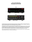
The HD88CC5 eight-source, eight-zone, high-definition matrix switcher allows Hi-Definition Video and
digital Audio signals to be sent over standard Coax cable or CAT5 cable with virtually no loss. Both
coaxial component and CAT5 video outputs are active simultaneously, making it possible to distribute
eight sources to sixteen outputs at the same time.
The HD88C has the same great features as the HD88CC5 without the CAT5 output. The HD88C is
ideal for installations requiring local switching and distribution up to 250’.
The HD88CC5 and HD88C units are expandable up to 32 discreet Outputs (ZONES) by paralleling
the inputs of up to 4 8x8 units.
SPECIFICATIONS
Size: 17” W x 7-3/4” D x 5-3/4” H
Weight: 12.6 lbs (12.6 kilos)
Controllable through IR and RS232 commands
Optional Rack Mount kit available (RM3UKIT)
Power Requirements (120VAC, 0.25A, 50-60Hz) Supports 220VAC with appropriate
Switch setting (See Rear Panel, Item #3)
Operates in temperatures up to 55 degrees Celsius
Video Input: Component Video YPbPr (YCbCr) – Gold Plated RCA
Audio Input: SPDIF PCM Coaxial – Gold Plated RCA
Active A/V Loop Thru (for Expansion): Gold Plated RCA
Bandwidth supports resolutions of 1080p, 1080i, 720p, 480p and 480i
Coax Output Distance: 250ft (76m) – Gold Plated RCA
CAT5/E Output Distance: 1,000ft (304m) – RJ45
08905150B
-1-
Safety Information
CAUTION: TO REDUCE THE RISK OF ELECTRIC SHOCK, DO NOT
REMOVE COVER (OR BACK). NO USER SERVICEABLE PARTS
INSIDE.
REFER SERVICING TO QUALIFIED SERVICE PERSONNEL.
The lightning flash with arrowhead symbol within an equilateral triangle
is intended to alert the user to the presence of uninsulated "dangerous
voltage" within the product's enclosure that may be of sufficient
magnitude to constitute a risk of electric shock to persons.
The exclamation point within an equilateral triangle is intended to alert
the user to the presence of important operating and maintenance
(servicing) instruction in the literature accompanying the appliance.
WARNING: TO REDUCE THE RISK OF FIRE OR SHOCK,
DO NOT EXPOSE THIS APPLIANCE TO RAIN OR MOISTURE.
IMPORTANT SAFETY INFORMATION
Read Information — All the safety and operating information should be read before the appliance is operated.
Follow Information — All operating and use information should be followed.
Retain Information — The safety and operating information should be retained for future reference.
Heed Warnings — All warnings on the appliance and in the operating instructions should be heeded.
Wall Mounting — Mounting of this appliance should be done only by an authorized installer.
Ventilation — The appliances should be situated so that their location or position does not interfere with their proper
ventilation. These appliances should never be placed near or over a radiator or heat register. These appliances should not
be placed in a built-in installation such as a bookcase or cabinet that may impede the flow of air through the ventilation
openings.
Non-Use Periods — Appliances that are left unattended and unused for long periods of time should be de-energized.
Grounding or Polarization — Do not defeat the safety purpose of the polarized or grounding-type plug. A polarized plug
has two blades with one blade wider than the other blade. A grounding type plug has two blades and a third grounding
prong. The polarized wide blade and the third prong are provided for your safety. If the provided plug does not fit your
outlet, consult an electrician for replacement of the obsolete outlet.
Power Cord Protection — Protect the power cord from being walked on or pinched particularly at plugs, convenience
receptacles and the point where they exit from the apparatus.
Water — Do not use the apparatus near water.
Cleaning — Unplug the apparatus from the power outlet before cleaning. Use only a dry cloth to clean the apparatus.
Power Lines — An outdoor antenna should be located away from power lines. When installing an outside antenna
system, extreme care should be taken to avoid touching power lines or circuits, as contact with them may be fatal.
Object and Liquid Entry — Never insert objects of any kind through the openings of these appliances, as they may
touch dangerous voltage points or short-out parts that could result in a fire or electric shock. Care should be taken so that
objects do not fall and liquids are not spilled into the appliance through openings in the enclosure.
Servicing — Do not attempt to service these appliances yourself, as opening or removing covers may expose you to
dangerous voltage or other hazards. Refer all servicing to qualified service personnel.
08905150B
-2-
Damage Requiring Service — These appliances should be serviced by qualified service personnel when:
• A power supply connection or a plug has been damaged or
• If liquid has been spilled into the appliance or objects have fallen into the appliance or
• The appliance has been exposed to water or moisture or
• The appliance does not appear to operate normally or exhibits a marked change in performance or
• The appliance has been dropped or the enclosure damaged.
Replacement Parts — When replacement parts are required, be sure the service technician has used replacement parts
specified by the manufacturer or that have the same characteristics as the original part. Unauthorized substitutions may
result in fire, electric shock, or other hazards.
Safety Check — Upon completion of any service or repairs to this audio product, ask the service technician to perform
safety checks to determine that the audio product is in proper operating condition.
Lightning Storms — Unplug this apparatus during lightning storms or when unused for long periods of time.
Attachments and Accessories — Use only attachments/accessories specified by the manufacturer.
Cart, Stand, Tripod, Bracket or Table — Use only with a cart, stand, tripod, bracket or table specified by the
manufacturer, or sold with the apparatus. When a cart is used, use caution when moving the cart/apparatus combination
to avoid injury from tip over.
Disconnect Device — Where the mains plug or an appliance coupler is used as the disconnect device, the disconnect
device shall remain operable.
NOTE: This equipment has been tested and found to comply with the limits for a Class B digital device, pursuant to part
15 of the FCC Rules. These limits are designed to provide reasonable protection against harmful interference in a
residential installation. This equipment generates, uses and can radiate radio frequency energy and, if not in-stalled and
used in accordance with the instructions, may cause harmful interference to radio communications. However, there is no
guarantee that interference will not occur in a particular installation.
If this equipment does cause harmful interference to radio or television reception, which can be determined by turning the
equipment off and on, the user is encouraged to try to correct the interference by one or more of the following measures:
• Reorient or relocate the receiving antenna.
• Increase the separation between the equipment and receiver.
• Connect the equipment into an outlet on a circuit different from that to which the receiver is connected.
• Consult the dealer or an experienced radio/TV technician for help.
CAUTION: Changes or modifications not expressly approved by Xantech could void the user’s authority to operate the
equipment
Caring For the HD88 High Definition Video Matrix Switcher
Clean only with a dry soft cloth.
It is important to properly care for your HD88 High Definition Video Matrix Switcher. Follow these guidelines to ensure
your device is preserved and protected.
• Do not expose the HD88 to rain, liquids or moisture for an extended period of time.
• Do not expose the HD88 to temperature extremes.
• Do not place any objects on top of the HD88 to prevent chassis damage.
Precautions
• Always exercise care when operating the HD88 High Definition Video Matrix Switcher.
• Do not install near any heat sources such as radiators, heat registers, stoves, or other apparatus (including
amplifiers) that produce heat.
• In the unlikely event that smoke, abnormal noise, or strange odor is present, immediately power the HD88 off.
Please report the problem to your dealer immediately.
• Never attempt to disassemble the HD88. You will lose any product warranty on the unit.
08905150B
-3-
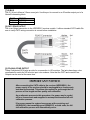
IMPORTANT NOTICE
HD44 Series and HD88 Series
INTRODUCTION
In some installation scenarios, an audio/video source component (such as a cable box or DVD
player) may fail to work properly with distribution products or even a display. The problem is often
related to the source component’s video outputs exhibiting too much DC offset voltage on the signal
line. The result of poor DC offset voltage conditioning on the output often results in color problems
such as color bleeding, picture clarity, definition, and stability issues.
VS100 DC BLOCKER
To resolve this issue, use a Xantech ‘VS100’
Video Stabilizer DC Blocker. The ‘VS100’ is
placed in between the source component output
and the input to the distribution product. Packaged
in convenient inline dongles, the ‘VS100’ requires
no additional cables or power connections. A
‘VS100’ DC Blocker set needs to be connected
between each source component with a DC offset
issue and its corresponding input on the HD88 or
HD44.
08905150B
-4-
DETAIL OVERVIEW
FRONT PANEL
The front panel is designed to provide the unit’s current Output/Input setting status. Note that only
one Output/Input status setting is displayed at any given moment. The top row of LED indicators
represents the current ZONE output selection. The bottom row of LED indicators represents the
current SOURCE input selection. The LED columns are numbered 1 to 8, from left to right.
To review the Zone/Input assignment, you must first perform a Zone Selection by pressing the
desired ZONE on the remote control. The unit will automatically update its display to show the
selected Output (ZONE) and its associated selected Input (SOURCE). The Output (ZONE) OFF
condition is identified by lighting the specified Output (ZONE) LED and leaving all (SOURCE) LED’s
off. To change the Input (SOURCE), press the desired SOURCE button. Modifying the Output (Zone)
to Input (Source) association for an Output (Zone) other than the one currently displayed on the front
panel will require two button presses. The first one changes the active Output (ZONE). The second
updates the Input (SOURCE) pairing.
.
08905150B
-5-
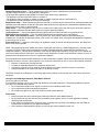
REAR PANEL
[1] SOURCE LOOP-THROUGH CONNECTION
The source inputs are buffered to provide an output at the same level as the input – i.e. Unity Gain
(assuming a 75-ohm termination is on the output). Use these connections for HD88 expansion
systems. The buffers are an active circuit. The HD88 must be powered on for an active connection.
The jacks are color-coordinated to match the HD source component output color scheme.
[2] SOURCE INPUTS
These are Gold-plated RCA jacks
providing a connection from the output
of a source component to the HD88.
The jacks are color-coordinated to
match the HD source component output
color scheme.
[3] AC POWER INPUT AND
EUROPEAN POWER SELECTION
SWITCH
This Standard IEC 3-Conductor AC Line
Cord Receptacle is utilized to plug-in a
3-conductor power line cord. Be sure to
note if the power receptacle is Domestic
(120VAC) or International (240VAC).
08905150B
-6-
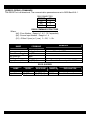
[4] RS232 (SERIAL) COMMANDS
The RS232 Port is bi-directional. The communication parameters are set to 9600 Baud 8-N-1.
DB9 CONNECTOR
CIRCUIT
PIN
TX
2
RX
3
GND
5
RS232 COMMAND STRUCTURE
Where:
{z#} - Zone Number. Range is 1..4 (1..16 if expanded)
{s#} - Source Input Number. Range is 1..4
{0/1} – Either 0 (zero) or 1 (one). 0 – Off, 1 – On.
NAME
REMARKS
COMMAND
Zone Power
!{z#}PR{0/1}+
Zone Power Toggle
All Zones Off
All Zones On
Input (Source) Select
!{z#}PT+
!AO+
!AA+
!{z#}SS{s#}+
To turn on Zone 2: !2PR1+
To turn off Zone 1: !1PR0+
To set Zone 1 to Source Input 5: !1SS5+
RS232 QUERIES
NAME
Zone Power
Input Select
08905150B
QUERY
?{z#}PR+
?{z#}SS+
RESPONSE
?{z#}PR{0/1}+
?{z#}SS{s#}+
EXAMPLE
?7PR0+
?5SS3+
EXPLANATION
Power in zone 7 is OFF.
Zone 5 is Source 3.
-7-
[5] RS232 EXPANSION
The HD88C and HD88CC5 can be expanded into larger systems. By using any combination of the
HD88C and HD88CC5 (up to 4 units), a larger High-Definition distribution system can be created for
up to 32 Zones of Component Video and Digital Audio Distribution.
The expanded HD88C units must have their own unique address (see ADDRESS (DIP SWITCH)
section). The included RS232 expansion cable allows the units to be daisy chained via the RS232
control ports. This is done by connecting the SERIAL LINK port of the master to the XANTECH COM
PORT of the other unit. The XANTECH COM PORT of the master is utilized to provide control of the
entire system. Note that the Master is the main controlling unit. This unit is in charge of coordinating
the communications between all expanded units. It is identified as the master by the unit address
assigned to it. Refer to the ADDRESS (DIP SWITCH) section for further details.
DB9 MALE
CIRCUIT
TX
RX
GND
3.5MM PLUG
PLUG
CIRCUIT
TIP
TX
RING
RX
SLEEVE GND
PIN
2
3
5
[6] ADDRESS (DIP SWITCH)
Switch 1 & 2: Unit Address (for Expansion mode)
ADDR
UNIT 1 (Master)
UNIT 2
UNIT 3
UNIT 4
SW 1
OFF
OFF
ON
ON
SW 2
OFF
ON
OFF
ON
Switch 3: Group Code Write Protect
Wr Protect SW 3
Protected
OFF
Unprotected ON
Switch 4: IR Receiver Select
IR Select
SW 4
Front IR Sensor
OFF
Enable
Rear IR Sensor Enable ON
08905150B
-8-
[7] IR BUS
The IR_IN port utilizes a 3.5mm mono jack. Use this port to connect to an IR emitter output port of a
Xantech connecting block.
PLUG
CIRCUIT
TIP
IR SIGNAL
SLEEVE GROUND
[8] CAT5 ZONE OUTPUT
This is an Output connection to the HDRXSG01 receiver module. It utilizes standard CAT5 cable. Be
sure to verify CAT5 wiring connection is correct before installation.
[9] COAXIAL ZONE OUTPUT
These Gold-plated RCA jacks provide for a connection to HD monitors. The jacks have been colorcoordinated to match the HD monitor input color scheme. Note that the CAT5 and coaxial Zone
Outputs can be used at the same time.
IMPORTANT NOTICE
After connecting the CAT5 cable to the receiver (HDRXSG01), the
power supply to the receiver should be unplugged for a few seconds
and then reconnected. This allows the receiver to go through the full
process of line length and line quality self-calibration.
As an alternate process to this procedure, the power may be cycled
off for a few seconds and reapplied to accomplish the same full selfcalibration process.
If for some reason the system loses power at the receiving end
(HDRXSG01), the transmitting end (HD88CC5), or both ends, the full
self-calibration process will automatically occur.
08905150B
-9-
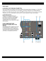
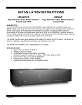
QUICK INSTALLATION: HD88CC5 and HDRXSG01
[1] Connect the High-Definition Source to the HD88CC5 or HDTXSG01. Figure 1 below shows an
HD88CC5 (video matrix transmitter) connected to the HDRXSG01 (receiver).
[2] Using CAT5 cable, connect the HD88CC5 zone output or the output from the HDTXSG01 to the
HDRXSG01. Connect power to the HD88CC5 first, then connect power to the HDRXSG01.
[3] On the HD88CC5, make the desired Zone/Source assignment. See HD88CC5 manual on how to
use RS232 and IR RC68+ controls.
[4] Installation Complete! No adjustments needed!
HD SOURCE 5
HD SOURCE 6
HD SOURCE 7
HD SOURCE 8
HD SOURCE 1
HD SOURCE 2
HD SOURCE 3
HD SOURCE 4
SOURCE 1 IN
Y
Y
Y
PB
SOURCE 2 IN
PR
SPDIF
Y
PB
SOURCE 3 IN
PR
SPDIF
Y
PB
SOURCE 4 IN
PR
SOURCE 1 OUT
SOURCE 2 OUT
SOURCE 3 OUT
SOURCE 5 IN
SOURCE 6 IN
SOURCE 7 IN
PB
PR
SPDIF
Y
PB
PR
SPDIF
Y
PB
SPDIF
Y
XANTECH COM POR
SOURCE 4 OUT
SOURCE 8 IN
PR
SPDIF
Y
PB
SOURCE 5 OUT
SOURCE 6 OUT
SOURCE 7 OUT
SOURCE 8 OUT
ZONE 2 OUT
BALANCED VIDEO OUT
ZONE 3 OUT
BALANCED VIDEO OUT
ZONE 4 OUT
BALANCED VIDEO OUT
PB
PR
SPDIF
Y
PB
PR
SPDIF
Y
PB
PR
SPDIF
Y
SPDIF
PR
PB
CAT 5
ZONE 5 OUT
BALANCED VIDEO OUT
BALANCED VIDEO OUT
ZONE 6 OUT
IR IN
SERIAL
LINK
BALANCED VIDEO OUT
ZONE 7 OUT
120 V AC, 60HZ, 20W
SPDIF
PR
ZONE 1 OUT
BALANCED VIDEO OUT
BALANCED VIDEO OUT
T
SPDIF
PR
PB
ADDRESS
ZONE 8 OUT
HDRXSG01
TV
MONITOR
HD DISPLAY
HD DISPLAY
TV
MONITOR
MONIT
CAT 5 X8
FIGURE 1
08905150B
- 10 -
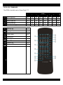
RC68+ (IR) COMMANDS
The RC68+ should be set to Group Code “F1”.
ZONE
1
2
3
4
5
Zone Selection
Source Selection
Zone Power On
Zone Power Off
Zone Power Toggle
1
80
40
60
28
E1
6
7
8
Zone All On
Zone All Off
Save Preset
F1
99
D9
9
Clear Preset
B9
10
11
12
13
14
Preset One
Preset Two
Preset Three
Preset Four
Restore All Zones
01
41
21
61
F9
08905150B
2
48
A0
88
E8
89
3
10
30
18
78
C9
4
90
B0
98
F8
A9
5
00
20
08
68
71
6
C0
E0
A8
C8
19
7
50
70
38
58
59
8
D0
F0
B8
D8
39
- 11 -
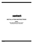
ADVANCE INSTALLATION
Sports Bar
The figure below shows a diagram for a sports bar application. With the equipment rack located near
or behind the bar area, the coaxial outputs can be used for local HD monitors. The CAT5 outputs can
be used to deliver HD content to areas such as outdoor patios and pool table recreational areas.
FIGURE 2
08905150B
- 12 -
Expanded System
The figure below shows an expanded HD88CC5 (16 Zones and up to 32 HD monitors) system. With
two HD88CC5 devices, HD content can be distributed to 32 displays (16 with CAT5 outputs, 16 with
coaxial outputs). The included RS232 expansion cable allows a single RS232 control port to be used
to command the entire system. Expansion specific communications between units is accomplished
via the Expansion Cable.
FIGURE 3
08905150B
- 13 -
Notes:
08905150B
- 14 -
Xantech Limited Warranty
(Effective for products sold after July 1, 2006)
Xantech Corporation (“Xantech”) warrants to the holder of a valid proof of purchase as the first end-user purchaser
(“You”), its products to be free from defects in materials and workmanship for the periods specified below from the date of
purchase. This limited warranty extends only to You for product purchased and used in the United States of America. For
product purchased outside of the United States of America, You must contact the Xantech authorized distributor in your
region for warranty services. Product is not intended for end user installation. If within the applicable warranty period
above You discover such item was not as warranted above and You promptly notify Xantech in writing, Xantech shall
repair or replace the items at its option. Xantech may elect which remedy or combination of remedies to provide in its sole
discretion. Xantech may use functionally equivalent reconditioned/refurbished/pre-owned or new products or parts under
this limited warranty. This warranty shall not apply (a) to product which shall have been installed by other than an
authorized Xantech installer, (b) to installed product which is not installed to Xantech’s specifications, (c) to product which
shall have been repaired or altered by others than Xantech, (d) to charges for installation or set up or adjustment of
customer controls, (e) to product that has suffered normal cosmetic deterioration (f) to product which shall have been
subjected to negligence, misuse, abuse, accident, or damage by circumstances beyond Xantech’s control, including, but
not limited to, lightning, flood, electrical surge, tornado, earthquake, or any other catastrophic events beyond Xantech’s
control, or (g) to product which shall have been subjected to improper operation, connected equipment failure or
malfunction, inadequate packing or shipping damage, maintenance or storage, or to other than normal use of service. The
foregoing warranties do not cover reimbursement for labor, transportation, shipping, removal, installation, or other
expenses which may be incurred in connection with repair or replacement. All claims for product shipping damage must
be processes within 3 days of receipt by You.
A Xantech Return Authorization (RA) must be obtained from Xantech by You, your installer or your distributor for Product
covered under this warranty. Covered product must be sent to Xantech together with proof of purchase, RA number,
prepaid and insured to Xantech. Freight collect shipments will be refused. Risk of loss or damage in transit is borne by the
sender. Xantech's warranty does not cover Products which have been received improperly packaged, altered, or
physically damaged. Products will be inspected upon receipt.
Except as may be expressly provided and authorized in writing by Xantech, Xantech shall not be subject to any other
obligations or liabilities whatsoever with respect to equipment manufactured or sold by Xantech or services rendered by
Xantech.
THE FOREGOING WARRANTIES ARE EXCLUSIVE AND IN LIEU OF ALL OTHER EXPRESSED AND IMPLIED
WARRANTIES, INCLUDING BUT NOT LIMITED TO IMPLIED WARRANTIES OF MERCHANTABILITY AND FITNESS
FOR A PARTICULAR PURPOSE.
ATTENTION: TO OUR VALUED CONSUMERS
To insure that consumers obtain quality pre-sale and after-sale support and service, Xantech products are sold
exclusively through authorized dealers and authorized distributors. The warranties on Xantech products are NOT VALID if
the products have been purchased from an unauthorized dealer or distributor. In order to determine if your Xantech reseller is authorized, please call Xantech (800) 843 - 5465.
XANTECH PRODUCT
(go to Xantech.com/warranty for model numbers)
IR Receivers and IR Emitters
Remote Control Switchers
Modules and Connecting Blocks
Accessories
Speakers
Volume Controls and Speaker Selectors
DIGI-5, MRC, BX, ZPR and Commercial Products
Amplifiers
Control Interfaces
Hand Held Remote Controls
SPLCD Product
Source Components, XIS100
08905150B
WARRANTY DURATION
Limited Lifetime
Limited Lifetime
Limited Lifetime
Limited Lifetime
Limited Lifetime
5 year Limited
2 year Limited
2 year Limited
2 year Limited
1 year Limited
1 year Limited
1 year Limited
- 15 -
Xantech Corporation
13100 Telfair Avenue
Sylmar, CA 91342
www.xantech.com
Phone: (818) 362-0353, Fax: (818) 362-9506
Installation Instructions, HD88CC5, HD88C © 2009 Xantech Corporation
This document is copyright protected. No part of this manual may be copied or reproduced in any form without prior
written consent from Xantech Corporation.
Xantech Corporation shall not be liable for operational, technical, or editorial errors/omissions made in this document.
Document Number 08905150B
08905150B
- 16 -