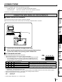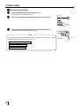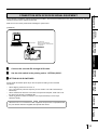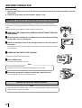
1
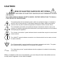
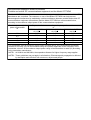
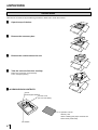
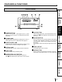
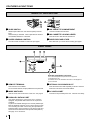
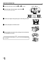
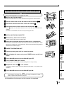
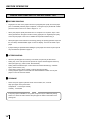
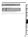
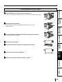
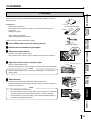
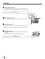
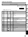
DIGITAL COLOR PRINTER
MODEL
CP770DW
OPERATION MANUAL
CP770DW
PAPER FEED
&CUT
ALARM
SHEET/PAPER
SCSI
COPY
ONLINE
DATA
POWER
OPEN
THIS OPERATION MANUAL IS IMPORTANT
TO YOU.
PLEASE READ IT BEFORE USING YOUR
DIGITAL COLOR PRINTER.
This digital color printer complies with the requirements of the EC
Directive 89/336/EEC, 73/23/EEC, 93/42/EEC and 93/68/EEC.
The electro-magnetic susceptibility has been chosen at a level that
gains proper operation in residential areas, on business and light
industrial premises and on small-scale enterprises, inside as well as
outside of the buildings. All places of operation are characterised by
their connection to the public low voltage power supply system.
WARNING:
In the USA or Canada, use the AC power cord according to the recommendations as below, in order to comply with
UL2601-1 and CAN/CSA C22.2 No. 601.1.
Case 1. Connect to the 120V receptacle of the room or the host equipment.
The AC power cord should be UL or CSA approved and consist of type SJT, size 16 or 18AWG, length
2.5m or shorter cord with IEC320/C13 type, 125V 10A or higher rating connector and NEMA 5-15 type,
125V 10A or higher rating, Hospital Grade plug.
Case 2. Connect to the 230V receptacle of the room or the host equipment.
The AC power cord should be UL or CSA approved and consist of type SJT, size 16 or 18AWG, length
2.5m or shorter cord with IEC320/C13 type, 250V 10A or higher rating connector and NEMA 6-15 type,
250V 10A or higher rating, Hospital Grade plug.
Case 3. Connect to the 120V receptacle of the host equipment.
The AC power cord should be UL or CSA approved and consist of type SJT, size 16 or 18AWG, length
2.5m or shorter cord with IEC320/C13 type, 125V 10A or higher rating connector and IEC320-2.2/E type,
125V 10A or higher rating plug.
Case 4. Connect to the 230V receptacle of the host equipment.
The AC power cord should be UL or CSA approved and consist of type SJT, size 16 or 18AWG, length
2.5m or shorter cord with IEC320/C13 type, 250V 10A or higher rating connector and IEC320-2.2/E type,
250V 10A or higher rating plug.
CAUTION:
Changes or modifications not expressly approved by the party responsible for compliance could
void the user’s authority to operate the equipment.
NOTE:
This equipment has been tested and found to comply with the limits for a Class A digital device,
pursuant to Part 15 of the FCC Rules.
These limits are designed to provide reasonable protection against harmful interference when
the equipment is operated in a commercial environment. This equipment generates, uses, and
can radiate radio frequency energy and, if not installed and used in accordance with the instruction manual, may cause harmful interference to radio communications.
Operation of this equipment in a residential area is likely to cause harmful interference in which
case the user will be required to correct the interference at his or her own expense.
Information:
This class A digital apparatus complies with Canadian ICES-003.
"CLASSIFIED BY UNDERWRITERS LABORATORIES INC.®
WITH RESPECT TO ELECTRIC SHOCK, FIRE AND MECHANICAL HAZARDS ONLY IN ACCORDANCE WITH UL2601-1 AND CAN/CSA C22.2 No. 601.1"
CAUTION:
RISK OF ELECTRIC SHOCK DO NOT OPEN.
TO REDUCE THE RISK OF ELECTRIC SHOCK,DO NOT REMOVE COVER
(OR BACK)
NO USER-SERVICEABLE PARTS INSIDE. REFER SERVICING TO QUALIFIED SERVICE PERSONNEL.
The lightning flash with arrowhead symbol, within an equilateral triangle, is intended to
alert the user to the presence of uninsulated "dangerous voltage" within the product's
enclosure that may be of sufficient magnitude to constitute a risk of electric shock.
The exclamation point within an equilateral triangle is intended to alert the user to the
presence of important operating and maintenance (servicing) instructions in the literature
accompanying the appliance.
The “Caution, hot surface” symbol indicates that the marked item may be hot and should
not be touched.
The “ON/OFF” symbol indicates connection to or disconnection from the mains, at least
for mains switches.
The “Equipotentiality” symbol identifies the terminals connected each other. The potential of various parts of equipment or of a system is equalized.
The “Alternating current” symbol indicates that the equipment is suitable for alternating
current only.
When you dispose of the unit or accessories, you must obey the law in the relative area or
country and/or regulation in the relative hospital.
WARNING:
Install and use this appliance in accordance with the operation manual for safety and EMC (Electromagnetic Compatibility). If it is not installed and used in accordance with the operation manual, it may cause
interference to other equipment and/or other risk.
To prevent fire or shock hazard, do not expose this appliance to rain or moisture.
This appliance must be earthed.
In Europe, use the AC power cord according to the recommendations as below, in order to comply with
EN60601-1 and EN60950.
Connect to the 230V receptacle of the room or the host equipment.
The AC power cord should be VDE approved and consist of core size 1mm2 or bigger, length 2.5m or
shorter cord with IEC320/C13 type, 250V 10A or higher rating connector and CEE(7)VII type or IEC 3202.2/E type, 250V 10A or higher rating plug.
Use the parallel cable according to the recommendations as below, in order to comply with EN60601-1-2.
The parallel cable with appropriate plug should be 2 m long or shorter, comply with IEEE1284 standard,
shielded, 62Ω impedance, ELECOM Co. Ltd. printer cable No. CPC-D2 or equivalent one.
Use the SCSI cable according to the recommendations as below, in order to comply with EN60601-1-2.
The SCSI cable with appropriate plug should be 1 m long or shorter, comply with SCSI II standard,
Mitsubishi Electric Corporation JC-50V50V or equivalent one.
This product is to be employed with medical equipment, just for reference purpose, not for medical
diagnostic purpose.
INSTRUCTIONS FOR MEDICAL USE
<according to the Medical Safety/EMC standard IEC/EN 60601-1-2>
MEDICAL ELECTRICAL EQUIPMENT needs special precautions regarding EMC and needs to be
installed and put into service according to the EMC information provided in the ACCOMPANYING
DOCUMENTS.
Portable and mobile RF communications equipment can affect MEDICAL ELECTRICAL EQUIPMENT.
Technical description
List of all cables and maximum length of the cable and transducers and other ACCESSORIES
Maximum length
Reference page in this operation manual
AC power cord
2.5 m
This page, the previous pages for safety and page 23 for
accessories
Parallel cable
2m
This page, the previous pages for safety and page 23 for
accessories
SCSI cable
1m
This page, the previous pages for safety and page 23 for
accessories
Print paper
Page 16 for print paper, Page 24 for accessories
WARNING:
The use of ACCESSORIES, transducers and cables other than those specified, with the exception of
transducers and cables sold by the manufacturer of the Model CP770DW as replacement parts for
internal components, may result in increased EMISSIONS or decreased IMMUNITY of the Model
CP770DW.
WARNING:
The Model CP770DW should not be used adjacent to or stacked with other equipment and that if adjacent or stacked use is necessary, the Model CP770DW should be observed to verify normal operation in
the configuration in which it will be used.
Guidance and manufacturer's declaration - electromagnetic emissions
The Model CP770DW is intended for use in the electromagnetic environment specified below.
The customer or user of the Model CP770DW should assure that it is used in such an environment.
Emission test
RF emissions
CISPR 11/EN 55011
Compliance
Group 1
RF emissions
CISPR 11/EN 55011
Harmonic emissions
IEC/EN 61000-3-2
Voltage fluctuations /
flicker emissions
IEC/EN 61000-3-3
Class B
Class A
Complies
Electromagnetic environment - guidance
The Model CP770DW uses RF energy only for its
internal function. Therefore, its RF emissions are very
low and are not likely to cause interference in nearby
electronic equipment.
The Model CP770DW is suitable for use in all
establishments, including domestic establishments and
those directly connected to public low-voltage power
supply network that supplies buildings used for
domestic purpose.
Guidance and manufacturer's declaration - electromagnetic immunity
The Model CP770DW is intended for use in the electromagnetic environment specified below.
The customer or user of the Model CP770DW should assure that it is used in such an environment.
Immunity test
Electrostatic
discharge (ESD)
IEC/EN 61000-4-2
IEC/EN 60601
test level
±6 kV contact
±8 kV air
Compliance
level
±6 kV contact
±8 kV air
Electromagnetic environment - guidance
Floors should be wood, concrete or
ceramic tile. If floors are covered with
synthetic material, the relative humidity
should be at least 30%.
Electrical fast
±2 kV for power ±2 kV for power Mains power quality should be that of a
typical commercial or hospital
transient/burst
supply lines
supply lines
IEC/EN 61000-4-4 ±1 kV for input
±1 kV for input environment.
/output lines
/output lines
Mains power quality should be that of a
±1 kV
±1 kV
Surge
typical commercial or hospital
differential
IEC/EN 61000-4-5 differential
environment.
mode
mode
±2 kV common ±2 kV common
mode
mode
<
5%
U
< 5% UT
Mains power quality should be that of a
T
Voltage dips, short
interruptions and
(> 95% dip in UT) (> 95% dip in UT) typical commercial or hospital
environment. If the user of the Model
voltage variations
for 0.5 cycle
for 0.5 cycle
CP770DW requires continued operation
on power supply
40% UT
40% UT
during power mains interruptions, it is
input lines
(60% dip in UT) (60% dip in UT) recommended that the Model CP770DW
IEC/EN 61000-4-11
for 5 cycles
for 5 cycles
be powered from an uninterruptible power
70% UT
70% UT
supply or a battery.
(30% dip in UT) (30% dip in UT)
for 25 cycles
for 25 cycles
< 5% UT
< 5% UT
(> 95% dip in UT) (> 95% dip in UT)
for 5 sec.
for 5 sec.
3 A/m
3 A/m
Power frequency
Power frequency magnetic fields should
(50/60 Hz) magnetic
be at levels characteristic of a typical
field
commercial or hospital environment.
IEC/EN 61000-4-8
NOTE UT is the a.c. mains voltage prior to application of the test level.
Guidance and manufacturer's declaration - electromagnetic immunity
The Model CP770DW is intended for use in the electromagnetic environment specified below.
The customer or user of the Model CP770DW should assure that it is used in such an environment.
Immunity test
IEC/EN 60601
test level
Compliance
level
Electromagnetic environment - guidance
Portable and mobile RF communications
equipment should be used no closer to
any part of the Model CP770DW,
including cables, than the recommended
separation distance calculated from the
equation applicable to frequency of the
transmitter.
Conducted RF
IEC/EN 61000-4-6
3 Vrms
150 kHz to 80
MHz
3 Vrms
Recommended separation distance
d=1.2√P
Radiated RF
IEC/EN 61000-4-3
3 V/m
80 MHz to 2.5
GHz
3 V/m
d=1.2√P 80 MHz to 800 MHz
d=2.3√P 800 MHz to 2.5 GHz
where P is the maximum output power
rating of the transmitter in watts (W)
according to the transmitter manufacturer
and d is the recommended separation
distance in meters (m).
Field strengths from fixed RF transmitters,
as determined by an electromagnetic site
survey,a should be less than the
compliance level in each frequency
range.b
Interference may occur in the vicinity of
equipment marked with the following
symbol:
NOTE1. At 80 MHz and 800 MHz, the higher frequency range applies.
NOTE2. These guidelines may not apply in all situations. Electromagnetic propagation is affected
by absorption and reflection from structures, objects and people.
a
Field strengths from fixed transmitters, such as base stations for radio (cellular/cordless)
telephones and land mobile radios, amateur radio, AM and FM radio broadcast and TV
broadcast cannot be predicted theoretically with accuracy. To assess the electromagnetic
environment due to fixed RF transmitters, an electromagnetic site survey should be
considered. If the measured field strength in the location in which the Model CP770DW is
used exceeds the applicable RF compliance level above, the Model CP770DW should be
observed to verify normal operation. If abnormal performance is observed, additional
measures may be necessary, such as reorienting or relocating the Model CP770DW.
b
Over the frequency range 150 kHz to 80 MHz, field strength should be less than 3 V/m.
Recommended separation distances between
Portable and mobile RF communications equipment and the Model CP770DW
The Model CP770DW is intended for use in the electromagnetic environment in which radiated RF
disturbances are controlled. The customer or user of the Model CP770DW can help prevent
electromagnetic interference by maintaining a minimum distance between portable and mobile RF
communications equipment (transmitters) and the Model CP770DW as recommended below,
according to the maximum output power of the communications equipment.
Rated maximum output
power of transmitter
W
Separation distance according to frequency of transmitter
m
150 kHz to 80 MHz
80 MHz to 800 MHz
800 MHz to 2.5 GHz
d=1.2√P
d=1.2√P
d=2.3√P
0.12
0.12
0.23
0.38
0.38
0.73
1.2
1.2
2.3
3.8
3.8
7.3
12
12
23
0.01
0.1
1
10
100
For transmitters rated at maximum output power not listed above, the recommended separation
distance d in meters (m) can be estimated using the equation applicable to the frequency of the
transmitter, where P is the maximum output power rating of the transmitter in watts (W) according
to the transmitter manufacturer.
NOTE1. At 80 MHz and 800 MHz, the separation distance for higher frequency range applies.
NOTE2. These guidelines may not apply in all situations. Electromagnetic propagation is affected
by absorption and reflection from structures, objects and people.
CONTENTS
PRECAUTIONS
1
2-4
5
6
7-8
SPECIAL
FEATURES &
UNPACKING
Contents ................................................................................................
Safety precautions ................................................................................
Special features ....................................................................................
Unpacking .............................................................................................
Features and functions .........................................................................
Front panel ............................................................................................. 7
Inside of Printing Unit ............................................................................. 8
Rear panel ............................................................................................. 8
Connections .......................................................................................... 9-11
BEFORE
FEATURES &
CONNECTIONS
FUNCTIONS
OPERATION
Connection with parallel data interface .................................................. 9-10
Connection with SCSI data signal equipment ........................................ 11
Before operation .................................................................................... 12-17
Removing transport screw and protective cushion ................................
Installation of print paper ........................................................................
Installation of ink sheet (For color print) .................................................
Usage and keeping of paper sheet set ..................................................
Installing printer driver ............................................................................
12
12-14
15
16
17
Troubleshooting .................................................................................... 18-20
Indication on the front panel & countermeasures .................................. 18
Overcoming paper jams ......................................................................... 19
Before calling for service ........................................................................ 20
Cleaning ................................................................................................ 21-22
Spec & options ...................................................................................... 23-24
Parallel data signal ................................................................................ 25-27
TROUBLESHOOTING
CLEANING
OTHERS
1
SAFETY PRECAUTIONS
In the interest of safety, please observe the following precautions:
POWER REQUIREMENT
This product is designed for operation on 100-120V AC or 220-240V AC 50/60Hz. Never connect to any outlet or power supply
having a different voltage or frequency.
WARNING: THIS APPARATUS MUST BE GROUNDED.
AVERTISSEMENT: CET APPAREIL DOIT ETRE MIS A LA TERRE.
PROTECTIVE MEASURES
IF ABNORMALITIES ARISE, ....
If the printer emits smoke or abnormal sounds, immediately unplug the power cord from the printer or power outlet. Continued
use is dangerous. Contact your dealer about having the printer checked and serviced.
NEVER INSERT ANY OBJECT INTO THE UNIT
Nothing other than supplies for this printer should ever be inserted into the printer. Other items can cause a safety hazard and
extensive damage to the mechanism and electronics.
DO NOT SET HEAVY OBJECTS ON TOP OF THE UNIT
Heavy objects can damage the unit and/or cause misoperation.
AVOID DAMAGING THE POWER CORD
Do not set anything heavy on the power cord nor allow it to become pinched, or cut. If the power cord becomes damaged,
replace it immediately to avoid shock hazard or electrical fire.
When the power cord is replaced, use the same type as originally supplied, it is designed to reduce interference to radio & TV
reception.
When unplugging the power cord, hold the plug, and remove it carefully.
KEEP THE UNIT DRY - DO NOT PLACE WATER OR OTHER LIQUID CONTAINERS, FLOWER VASES/POTS ON
TOP OF THE UNIT
Liquids which get into the unit can cause serious damage to the unit and potential shock or fire danger. If liquid is spilled into or
seeps into the unit, unplug the Power Cord immediately and seek service as soon as possible to avoid additional or possible
damage due to corrosion.
“In the interest of safety, avoid handling of liquids near the unit.”
DO NOT REMOVE THE CABINET. THERE ARE NO USER SERVICEABLE PARTS INSIDE AND YOU WILL EXPOSE
YOURSELF TO HAZARDOUS VOLTAGES AND/OR YOU MAY CAUSE DAMAGE TO THE UNIT.
Touching internal parts is dangerous, and may cause a malfunction. Contact your dealer to carry out internal checks and
adjustments. Disconnect the power cord before opening the cover to clear a paper jam, etc.
UNPLUG THE POWER CORD DURING A LONG ABSENCE OR DURING A ELECTRICAL STORM
Turn off the Main Power switch and unplug the power cord during a long absence or during a electrical storm.
WHEN SHIPPING OR TRANSPORTING THE UNIT
Always use the protective cushion and transport shipping screw to avoid damage to the printer during shipping or transportation.
Remove the ink sheet cartridge and paper from the mechanism, and insert the protective cushion into the ink sheet cartridge
area. Remove the mechanism transportation screw from the rear panel and secure the mechanism at the bottom with the
screw.
BE CAREFUL AROUND PRINT PAPER EXIT SLOT
Do not insert your fingers or any object into the paper slot during printing.
Do not touch the cutter blade inside the paper exit slot, it can cause injury.
DO NOT TOUCH THE THERMAL HEAD
It becomes hot during printing and may remain hot for a time, causing injury. Oils, salts and moisture form your hands will
contaminate the head and may spoil the prints.
2
BE CAREFUL WITH THE PRINTING MECHANISM
PRECAUTIONS
Do not move the printer while the printing mechanism is slid out. This may cause injury.
Be careful not to catch your fingers in the printing mechanism when sliding the mechanism back into the normal closed position.
CONNECTING CABLES
Use the power cord supplied with the printer. When connecting the unit with an equipment with parallel data interface, use the
parallel cross-over cable.
INSTALLATION LOCATIONS
Ventilation slots and holes are provided on the rear, sides and bottom of this unit. Place the unit on a hard and level surface and
locate at least 4 inches (10.16 cm) from walls to insure proper ventilation. When installing the unit in a system rack, leave space
between the unit and the back of the rack.
SPECIAL
FEATURES &
UNPACKING
MAINTAIN GOOD VENTILATION
UNSUITABLE LOCATIONS
PLACES WITH HIGH HUMIDITY AND DUST
Do not place the unit in locations with high humidity and dust. They can cause extensive damage. Avoid places where unit is
likely to be exposed to oily fumes and vapours.
PLACES NOT LIKELY TO BE EXTREMELY HOT
Places exposed to direct sunlight, or near heating appliances can attain extremely high temperatures which may deform the
cabinet, or cause other damage.
PLACE THE UNIT ON A HORIZONTAL SURFACE
The unit is likely to be affected if it is operated tilted, inclined or in unstable places.
PROTECT AGAINST DEW FORMATION
When the unit is moved from a cold area into a warm area, moisture can condense inside the unit and prevent operation. Allow
the temperature to stabilize before use.
OPERATING AMBIENT TEMPERATURE RANGE
The operating temperature range is 41°F - 104°F (5°C to 40°C) and humidity of 20 - 80%. When using the unit in a system rack,
make sure that the temperature inside the rack does not exceed this range.
BEFORE
FEATURES &
CONNECTIONS
FUNCTIONS
OPERATION
Avoid installing the printer in unstable locations with high vibration or in hot-springs areas where hydrogen sulfide and acidic
ions are likely to be generated.
TROUBLESHOOTING
FOR LONG OPERATING LIFE
UNSUITABLE MATERIALS FOR THE PRINTER
CLEANING
Paint coat flaking and plastic deformation are likely to occur if the unit is wiped with chemical dusters, benzine, thinner or any
other solvent, if rubber or PVC items are left in contact with the unit for a extended period, or if the unit is sprayed with
insecticide.
CARE OF THE CABINET
Unplug and clean with a soft cloth slightly moistened with a mild soap and water solution. Allow to dry completely before
operating. Never use petroleum base solutions or abrasive cleaners.
HEAD ABRASION
OTHERS
The thermal printhead, like a video head, wears out. When it is worn, it becomes hard to print out fine details of the picture.
Then it is necessary to replace the thermal head. Consult your dealer about having the head replaced.
3
SAFETY PRECAUTIONS
CONNECTING DEVICES
Read thoroughly the Safety Notices, Cautions and “Operating Precautions” of the instruction booklets for the other devices
connected with the unit.
CAUTION ON RELOCATING
When transporting this unit, make sure it is not likely to be subjected to impacts. They can be a primary cause for damage.
Always use the mechanism protective cushion and the transport shipping screw when shipping the unit. Before moving the unit,
make sure to disconnect the power cord from the power outlet, and the cables from the connected devices.
SAFETY CHECKS
Periods:
Scope: a)
According to the recommendations of the manufacturer of medical device.
Visual inspection
Housing, leads, controls, displays, labels/ markings, accessories, operation manual.
b)
Functionality test
Testing of functions (according to operation manual) as well as compatibility and usability of device and accessories.
c)
Electrical test
Testing of electrical safety of the system according to EN60601-1.
High humidity or dust
Avoid locations with high humidity and dust in order to avoid malfunctioning of the device.
Also avoid locations subject to corrosive gasses and smoke.
Heat
Direct sunlight, heaters or other heat sources may deform the housing and subsequently cause malfunctioning.
TECHNICAL DESCRIPTION
The supplier will make available on request such circuit diagrams, component part lists, descriptions, calibration instructions or other information
which will assist the USER’s appropriately qualified technical personnel to repair those parts of the EQUIPMENT which are classified by the
manufacturer as repairable.
The use of ACCESSORY equipment not complying with the equivalent safety requirements of this equipment may lead to a reduced level of
safety of the resulting system. Consideration relating to the choice shall include:
- use of the accessory in the PATIENT VICINITY
- evidence that the safety certification of the ACCESSORY has been performed in accordance to the appropriate EN60601-1 and/or EN60601-11 harmonized national standard.
The transportation and storage environmental conditions are:
Temperature : -20°C - +60°C (-4°F - +140°F)
Humidity : 90%RH or less at 40°C(104°F)
Note : The above transportation environmental conditions indicate the storage environmental conditions during transport.
OTHER CAUTIONS
Dust or other foreign matter adhering to the print paper or the sheet cartridge, or deformation resulting from exposure to
extremely low or high temperatures could cause loss of color, uneven color or lines, or wrinkles in the print images.
NOTE:
MEMORIZED IMAGES ARE STORED IN VOLATILE MEMORY AND MAY BE LOST IN THE EVENT OF POWER
FLUCTUATION OR MALFUNCTION.
As for paper sheet set, refer to page 24, “Options”.
4
SPECIAL FEATURES
SPECIAL FEATURES
PRECAUTIONS
3 PRINT SIZES ARE AVAILBLE ACCORDING TO THE PURPOSE
3 printing sizes, LL size (max.150 x 104.8 mm), L size (max.130 x 104.8 mm) and S size (max.104.8 x 75 mm), are selectable.
HIGH SPEED PRINTING
Printing speed is approx.19 seconds (in S size print). Use of roll paper shortens the time for installing and removing.
SPECIAL
FEATURES &
UNPACKING
LARGE CAPACITY PRINTING
Maximum of 200 prints per roll with S size media. Large capacity per roll reduces time for frequent media loading.
HIGH QUALITY PRINTING
CP770DW is a dye sublimation thermal transfer color printer which produces superior high quality images. It also produces a
continuous tone at 256 gradient and 16.7 million colors for each YMC.
BEFORE
FEATURES &
CONNECTIONS
FUNCTIONS
OPERATION
325 PPI HIGH RESOLUTION
CP770DW has a 325 PPI high resolution for precise illustrations and sharp photographic images.
MULTI AND WIDE PRINT FOR VARIOUS REQUIREMENTS OR APPLICATIONS
4 and 16 images of multi print and wide prints are available. These modes are selectable according to your requirements or
applications.
WIDE COMPATIBILITY WITH A VARIETY OF INTERFACE AND SYSTEMS
(1)
(2)
(3)
(4)
High speed transfer by centronics interface which corresponds to IEEE1284
Input and output control signals from SCSI II interface (Optional).
Reduced time of PC processing by a newly developed driver.
Compatible with prior printer models CP700DU(DE) and CP700DSU(DSE).
TROUBLESHOOTING
CLEANING
OTHERS
5
UNPACKING
UNPACKING
Take the unit out of the box by the following procedures. Make sure to check the contents.
1
Open the top of the box.
2
Remove the accessory box.
3
Remove the cushion above the unit.
4
Take the unit out of the box carefully.
Make sure to keep the unit horizontally.
Then, unwrap the packing.
2 ACCESSORY BOX CONTENTS
Spacer
Thermal paper bobbins
2 Power cords
(US- and CE cables)
Operation manual
Warranty card
Sheet “Installing print paper and ink sheet”
Printer driver (CPD770W)
Ink cassette
6
FEATURES & FUNCTIONS
2
3
4
5
6
7
PRECAUTIONS
FRONT PANEL
8
CP770DW
ALARM
SHEET/PAPER
OPTION
COPY
SPECIAL
FEATURES &
UNPACKING
PAPER FEED &CUT
ONLINE
DATA
9
POWER
OPEN
1
10
7 COPY BUTTON
2 ALARM LAMP
8 ONLINE BUTTON
Press to turn on power . Press again to turn of f power.
When the power is turned on, the lamp above this button
illuminates.
When this unit is overheated, this lamp goes on and of f.
When other error occurs, it illuminates. See page 18.
3 SHEET/PAPER LAMP
Illuminates when ink sheet or print paper is used up or any
trouble occurs in the sheet cartridge or print paper.
Illuminates when an option (SCSI) interface is selected.
Goes on and off during transferring data.
8
Press to switch the PC connection between ONLINE and
OFFLINE. When ONLINE is selected, you can control this
unit through PC. When on line is selected, this lamp
illuminates.
Press again to select OFFLINE (The light will be turned
off).
9 PRINT OUTLET
A OPEN BUTTON
The printed paper comes out here.
Press to slide out the printing mechanism. Open the
mechanism to load paper and ink or to clear a paper jam.
Pressing this button, the print paper is fed and cut.
When ON LINE lamp is lit, this button is not functional.
8
TROUBLESHOOTING
4 OPTION LIGHT
5 DATA LAMP
6 PAPER FEED & CUT BUTTON
When pressing this button, the transferred data will be
printed. When
ON LINE lamp is lit, this button is not
functional.
BEFORE
FEATURES &
CONNECTIONS
FUNCTIONS
OPERATION
1 POWER BUTTON
CLEANING
OTHERS
7
FEATURES & FUNCTIONS
INSIDE OF PRINTING UNIT
5
4
3
2
1
1 SLIDE SWITCH
3 INK CASSETTE COMPARTMENT
4 INK CASSETTE LOCKING LEVER
5 PAPER RELEASE LEVER
Load the cassette with ink sheet.
Selects input PARALLEL and OPTION (SCSI) terminal
input.
Default setting is OPTION. When optional SCSI board is
not installed, PARALLEL is selected.
Push this lever to take the ink cassette out.
2 PAPER SENDING CONTROL
Turn this control clockwise to rewind the print paper.
Move this lever up or down when inserting print paper.
REAR PANEL
3
2
SCREW
REMOTE
12345678
ON
OFF
1 2 3 4 5 6 7 8
OFF
1
4
PARALLEL DATA IN
AC LINE
5
Potential equalization connector
This is used to equalize the potential of the equipment
connected to the unit.
For details, refer to the installation instruction of the equipment
to be connected.
1 REMOTE TERMINAL
4 OPTIONAL SCSI BOARD SLOT
2 MODE SWITCHES
5 AC LINE SOCKET
This terminal is not available.
Do not use this terminal, except qualified service personnel.
Used to set the various functions of this unit. See page 9.
3 PARALLEL DATA IN PORT
Use these terminals to connect this unit to a device
equipped with parallel data interface such as personal
computer.
To prevent accidental damage to the unused parallel input,
keep the attached protective cover onto the terminal, when
not connecting the cable. When using the optional SCSI
board terminals, fix the protective cover with the plate and
screw which are attachted to the optional board (SB770).
See page 11 for connection.
8
Insert the SCSI board sold separately to this slot. See the
instruction manual for SCSI board SB770.
Connects to the provided power cord. Insert the cord firmly
.
CONNECTIONS
PRECAUTIONS
The unit is compatible with each of the following input signals.
• Parallel data signal : for Centronics compatible Parallel data interface
• SCSI data signal
: Refer to the operation manual of the optional SCSI board.
“Centronics” is a registered trademark of Centronics Data Corporation.
CONNECTION WITH PARALLEL DATA INTERFACE
2 CONNECTING WITH PC (EXAMPLE)
SPECIAL
FEATURES &
UNPACKING
Connect this unit with Personal computer as following example.
Make sure to turn off the power of the unit and the connecting equipment before connection.
BEFORE
FEATURES &
CONNECTIONS
FUNCTIONS
OPERATION
To
PARALLEL DATA IN
PC
MODE switches
1 2 3 4 5 6 7 8
1
2
OFF
ON
OFF
87654321
PARALLEL DATA IN
AC LINE
Connect the unit with PC through parallel cable.
When installing optional board and using parallel data interface,
set the slide switch in the printing unit to “PARALLEL”.
•
OFF
1 2 3 4 5 6 7 8
OFF
12345678
No. 1 No. 2 No. 6 Mode
Details
OFF OFF OFF Standard mode
When printing with the driver for CP770DW
ON
OFF OFF Compatible mode1 (fine print)*
When printing with the driver for CP700DU/DE and CP700DSU/DSE
ON
ON
OFF Compatible mode1 (standard print)** When printing directly from HC-300, DS-300/330 series with SCSI I/F (option)
ON
OFF ON
Compatible mode2 (fine print)**
When printing directly from HC-300Z series with SCSI I/F (option)
ON
ON
ON
Compatible mode2 (standard print)** When installing thermal paper, thermal printing is available.
* fine print : Image quality priority mode
** standard print : Printing speed priority mode
*** When setting the mode switch No.6 to OFF, thermal printing is not available unless the driver selects thermal paper.
Do not set the mode switches No.1, 2 and 6 any other settings except the above.
With the mode switch No. 4, set the mirror print.
OFF ........ Normal print
ON .......... Mirror print
OTHERS
•
•
ON
CLEANING
Set the mode switches (DIP-SW) on the rear panel.
• All the switches are set to OFF as shown right when shipping.
• Set the mode switches No. 1, 2 and 6 according to the printer driver to be used.
• Set to Standard mode when using the printer driver supplied with this unit.
• Set to Compatible mode 1 when using printer drivers (CPD-04/CPD-05) for
CP700DU/DE and CP700DSU/DSE.
TROUBLESHOOTING
2 SETTING MODE SWITCHES
Set the mode switches No. 3, 5, 7 and 8 to OFF.
9
CONNECTIONS
2 SETTING ON LINE STATUS
1
2
Press POWER button to turn on this unit.
•
The lamp above the POWER button is lit.
Turn on the power of the personal computer connected.
POWER
3
Confirm that the ON LINE button on the front panel is lit.
•
When ON LINE is selected, the lamp illuminates.
CP770DW
PAPER FEED &CUT
NOTE
You do not need to press the ONLINE button when it is already lit. In the following conditions,
ON LINE lamp illuminates when turning on the power.
•Installing printing paper and ink sheet.
+
•Inserting printing unit correctly.
+
•Available to receive the data.
10
COPY
ONLINE
PRECAUTIONS
CONNECTION WITH SCSI DATA SIGNAL EQUIPMENT
SCSI interface is available if optional SCSI board is installed. SCSI board is installed at the rear option slot of the unit. See the
operations manual of the optional SCSI board.
Make sure to turn off the power before installing the option board.
(EXAMPLE)
SPECIAL
FEATURES &
UNPACKING
PC, etc.
To SCSI port
(When not connecting to
other equipment, the terminator
is required.)
BEFORE
FEATURES &
CONNECTIONS
FUNCTIONS
OPERATION
To SCSI port
Terminator
SCSI
SCSI ID
SCSI
1 2 3 4 5 6 7 8
OFF
ON
OFF
87654321
PARALLEL DATA IN
AC LINE
SCSI ID switch
1
2
Connect the unit with PC through SCSI cable.
Set the slide switch in the printing unit to “OPTION (SCSI)”.
2 SETTING SCSI ID SWITCHES
•
•
•
When shipping, SCSI ID is set to No. 5.
No.7 is provided for personal computer you use and No. 0 for built-in hard disk (of
Macintosh).
When another SCSI device is connected to the personal computer, make sure to set
the SCSI ID of this unit to a different ID#.
Select the SCSI ID number to between 1 and 6 (for Macintosh) or 0 and 6 (for
Windows®95/98).
CLEANING
•
TROUBLESHOOTING
Set the SCSI ID switches (SCSI ID) on the rear panel according to the connected
equipment.
NOTE
When this unit is not connected to other equipment except the host computer
, terminate
the port with the terminator supplied with optional SCSI board.
OTHERS
11
BEFORE OPERATION
Before printing,
1. Remove the transport screw on the bottom of printing mechanism and the protective cushion.
(See below)
2. Install the print paper and ink cassette. (pages 13-15)
REMOVING TRANSPORT SCREW AND PROTECTIVE CUSHION
To prevent damage during transportation/shipping, a protective cushion is inserted into the
mechanism, and the printing mechanism is locked into position from the bottom with a transport
screw.
Remove the screw by the following procedures before using this unit.
2 REMOVING THE TRANSPORT SCREW ON THE BOTTOM OF PRINTING
MECHANISM
Transport screw
1 Turn the printer carefully onto one side and remove the transport locking
screw with a coin or screwdriver.
the printer.
The transport screw and protective cushion must always be used during shipping or transport
to avoid damage.
2 REMOVING THE PROTECTIVE CUSHION
Unplug the power cord from outlet for safety.
1 Press OPEN button.
The printing unit advances to the front.
NOTE
Do not touch the thermal head.
Fingerprints or dust on the thermal head will degrade the print quality.
2 Remove the protective cushion from the right side of the unit.
Save the protective cushion for transporting the unit.
INSTALLATION OF PRINT PAPER
NOTE
When using this unit for printing, make sure to use the specified types of paper sheet and ink
sheet set. Refer to page 24 “OPTIONS”.
12
REMOTE
12345678
ON
OFF
1 2 3 4 5 6 7 8
OFF
2 Attach the transport screw to the storage location on the rear panel of
SCREW
PARALLEL DATA IN
AC LINE
2 INSTALLING MONOCHROME THERMAL PAPER
PRECAUTIONS
1 Put the supplied bobbins on the both sides of the thermal paper
Bobbin with
gear
Bobbin
without gear
roll.
NOTE
Set the bobbins as shown in the right figure. Make sure to put the bobbin on the
correct position.
SPECIAL
FEATURES &
UNPACKING
2 Unroll the thermal paper about 20cm (8 inch) and cut it not to use
Incorrect
sticky part.
Remove the sticky part, dust, or fingerprints on the paper.
NOTE
Cut
Cut
Cut
20cm
Ink sheet is not needed for thermal printing.
The thermal paper setting is completed.
NOTE
Sheet cartridge error appears when an ink sheet is installed though the printer driver
selects thermal paper.
The error appears during data transfer and start of printing operation.
2 INSTALLING PRINT PAPER
1 Move the paper release lever toward the front of the printer as
shown by the arrow.
TROUBLESHOOTING
Holder
Print paper
Place the gear to the right side.
CLEANING
2 Insert the print paper in the position as shown right.
BEFORE
FEATURES &
CONNECTIONS
FUNCTIONS
OPERATION
3 Cut both edges of the paper.
Insert
Holder
To set the left side, press the holder in the unit to the left and insert the print paper roller
.
OTHERS
Print paper
13
BEFORE OPERATION
3 Insert the print paper under Roller 1 and 2 in order.
Roller
3
Roller
2
Roller
1
4 Insert the edge of the print paper under Roller 3.
Be sure to insert the paper straight.
Print paper
Paper
5 Feed the print paper through the paper outlet with your hand.
6 Pull the print paper to eliminate slack.
7 Move the knob on the side of the printing unit to the direction
as indicated by the arrow.
NOTE
If too much paper is fed,ALARM lamp may light. In this case, press P
APER FEED
& CUT button.
14
Paper
Paper
NOTE
When using thermal paper, do not install the ink sheet.
2 INSTALLING THE INK SHEET
On the
D position, turn the roller and set the notch of the roller side to the hole of the
cassette.
The roller can be installed when the notch is put through the hole.
E
B
A
Colored roller
E
D
hole
notch
BEFORE
FEATURES &
CONNECTIONS
FUNCTIONS
OPERATION
1 Put the colored roller of the ink sheet to the ink cassette. AB
2 Put the thin stick of white roller to the ink cassette. C
3 Put the thick stick of white roller to the ink cassette. DE
C
White roller
SPECIAL
FEATURES &
UNPACKING
Load the ink cassette with the ink sheet rolls before inserting the ink cassette into the
unit.
PRECAUTIONS
INSTALLATION OF INK SHEET (For color print)
2 INSTALLING THE INK CASSETTE
1 Eliminate any slack of the ink sheet.
Hold the colored roller and turn the white roller.
2 Insert the ink cassette with the ink sheet into its compartment.
Insert the ink cassette with the knob side toward you until it is locked into place. When
taking the ink cassette out of the compartment, press the ink cassette locking holder to
release the lock. Refer to page 8.
2 INSERT THE PRINTING UNIT
TROUBLESHOOTING
1 Push the printing unit until it is locked into place.
2 After plugging the power cord, press POWER button on the front
panel.
3 Press ONLINE button to set the ONLINE light OFF.
4 Press PAPER FEED &CUT button.
The print paper is automatically cut after feeding about 10 cm (4 inches).
CLEANING
5 Repeat the above step 4 once or twice.
Fingerprints and dust can be removed by feeding the print paper . The printing unit is
initialized.
6 Press ONLINE button to set the ONLINE light ON.
OTHERS
•
NOTE
Do not feed the print paper more than 2 times. Doing so will limit the number of
prints per paper roll as specified on page 24.
The installation of print paper and ink cassette is completed.
15
BEFORE OPERATION
USAGE AND KEEPING OF PAPER SHEET SET
2 BEFORE PRINTING
•
Fingerprints or dust on the paper’s surface may degrade print quality and cause paper
jams. Immediately after the paper is replaced, 2-3 images may be printed with a blank
part due to hand’s dust or oil. Refer to Pages 13 - 14.
•
When print paper is rapidly transferred from a cool place to a hot place, vapor or dew
will be generated on the paper’s surface causing paper jams or degraded print quality.
Leave the print paper in the room to stabilize its temperature before using it.
•
When print paper and ink sheet run out during printing, the printing operation stops and
the error lamp “SHEET/PAPER” lights on the LCD display. Set new ink sheet or print
paper.
•
If paper feeding is repeated while installing the print paper, the number of prints per roll
may be limited as specified on page 24.
2 AFTER PRINTING
•
When the printed paper is touched by a wet hand, the print may be discolored.
•
Fading may occur if the print-face is exposed to organic chemical agents which may
affect print paper (e.g. alcohol, ester, ketone based).
•
Fading will be accelerated upon contact with PVC-based materials (e.g. adhesive
tapes, rubber erasers, etc.).
•
•
Avoid storing prints in direct sunlight or places with high humidity.
Leaving the print paper in contact with PVC-based materials causes color of print
paper to come off and to be stained.
2 STORAGE
•
Never store print paper in places that are close to heater, hot, or humid.
Keep print paper in the place where:
Temperature : 5°C-30°C(41°F-86°F)
Humidity : 20-60%RH
NOTE
If the print paper is installed for a long time, the prints may be rolled after printing.
There is no cause for alarm because the print paper is rolled on the inside of the
printing unit.
16
PRECAUTIONS
INSTALLING PRINTER DRIVER
Printer driver is required to print the data from a personal computer connected with this
unit.
The printer driver for Windows® is supplied with this unit.
Operating conditions
For Windows®
Applies for Microsoft®Windows®95 and Windows®98
For Windows NT®
Applies for Microsoft®Windows NT®4.0
Refer to the operation manual of the driver software or “Read me” for installing.
SPECIAL
FEATURES &
UNPACKING
Product name
BEFORE
FEATURES &
CONNECTIONS
FUNCTIONS
OPERATION
If you use Macintosh computer, the optional SCSI board SB770 is needed.
Windows®95, Windows®98 and Windows NT® are the registered trademarks of Microsoft Corporation in the U.S.A. and other
countries.
TROUBLESHOOTING
CLEANING
OTHERS
17
TROUBLESHOOTING
INDICATION ON THE FRONT PANEL & COUNTERMEASURES
If for some reason printing is not possible or error occurs during printing, the indicator on the front panel will be lit.
In this case, follow the procedure described below.
: lit
: goes on and off
: not lit
ALARM SHEET/PAPER OPTION DATA
Causes and countermeasures
Page
The printing unit is not inserted correctly.
• Insert the printing unit until it is locked.
15
The sheet cartridge is not installed. *Note : 1
• Install the sheet cartridge.
15
Paper is not set.
Paper is not set correctly.
• Set the print paper correctly.
Paper or ink sheet runs out during printing. *Note : 2
• Install the sheet cartridge.
The temperature of the thermal head becomes too
13-14
15
high.
• Wait until the message goes off. *Note : 3
Paper jamming occurs.
Other defects.
• Refer to “Overcoming paper jams”.
• Make sure the ON LINE lamp is not lit, and press
19
PAPER FEED & CUT button.
If the status is not improved by carrying out this
measure, consult your dealer. *Note : 4
18
*Note : 1
The lamp goes on and off after transferring data and just before starting printing operation.
*Note : 2
*Note : 3
In case of L-size printing, the image is not printed completely.
When setting the continuous printing, the continuous printing is carried out after the error message goes off.
*Note : 4
When the printing unit is pulled out, PAPER FEED & CUT button is invalid.
After pushing the printing unit until it is locked into place, press the PAPER FEED & CUT button.
PRECAUTIONS
OVERCOMING PAPER JAMS
1 Press OPEN button to pull out the printing unit.
When it is not working, turn off the power once. Then try to press OPEN button again.
BEFORE
FEATURES &
CONNECTIONS
FUNCTIONS
OPERATION
Unlock the ink cassette by pushing the cassette locking lever to inside.
(Refer to Page 8.)
SPECIAL
FEATURES &
UNPACKING
2 Remove the ink cassette.
3 Turn the knob on the right side of the printing unit clockwise.
Roll up the print paper completely.
4 Remove the print paper.
5 Cut the defective part of the print paper with scissors.
TROUBLESHOOTING
6 Cut both edges of the print paper.
7 Install the print paper. (Refer to pages 13-14.)
CLEANING
OTHERS
19
TROUBLESHOOTING
BEFORE CALLING FOR SERVICE
2
Use the following troubleshooting chart to try to resolve any apparent defect in operation.
Symptom
Check and Remedy
No power
Is the power cord plug disconnected from the outlet?
→Connect the power cord plug to the outlet firmly.
→In an event of power failure, turn the power OFF and wait approx. 2 minutes
to reset the power back ON.
The image is not printed.
Is the image data sent to this unit?
→Confirm that the image data is sent to this unit.
Is the print paper or ink sheet used up?
→Check the status.
Is the printing unit set correctly?
→Set the printing unit correctly.
The stored image in the memory cannot be
Is the appropriate image data transferred?
enlarged to fill the maximum print area.
Is the printer driver set to the correct media size?
The image can not be transferred.
Is the ON LINE lamp lit?
→Press the ON LINE button.
Is the slide switch in the printing unit set correctly?
→Set the slide switch correctly.
COPY button does not work.
Is the image transferred?
Is the ON LINE lamp lit?
→Turn off the ON LINE lamp.
The host coputer does not recognize this unit.
Is the SCSI ID switch setting duplicated with another device setting?
→Check the SCSI ID switch setting.
20
CLEANING
A small amount of alcohol
Cleaning as indicated below will help maintain stable printer operation and extend
the printer’s life.
Preparations
Cotton buds
Cleaning kit (Option)*
Cleaning part
How to fold tissue paper
Metal spatula
Cleaning kit (Option)
Other : Cleaner pen (Option)*
*Please ask the dealer about options.
SPECIAL
FEATURES &
UNPACKING
Alcohol (isopropyl alcohol)
Tissue paper (Fold in half about 4 times, and use the folded side to clean.)
PRECAUTIONS
CLEANING
1 Press OPEN button to pull the printing unit out.
2 Remove the ink cassette and print paper.
3 Wipe the ink sheet sensor.
BEFORE
FEATURES &
CONNECTIONS
FUNCTIONS
OPERATION
Make sure to turn off the power before cleaning.
Cleaner pen (Option)
Ink sheet sensor
Clean the parts which the arrows show.
Wipe dust with cotton buds etc. which is soaked in a small amount of alcohol.
ENLARGE SIZE
4 Wipe the ink sheet sensor reflection plate.
Reflection plate fixing screw
Clean the metal reflection plate.
Wipe with tissue paper etc. which is soaked in a small amount of alcohol carefully
.
NOTE
Reflection plate transport screw is fixed with bonding agent. Do not wipe this
bonding agent.
Ink sheet sensor reflection plate
TROUBLESHOOTING
Thermal head
5 Wipe the head.
Cleaning the part under the thermal head which develops heat.
Wipe the head cleaning part carefully with tissue paper etc. which is soaked in a
small amount of alcohol.
NOTE
Do not damage the thermal head.
•
When the symptom of the poor print quality is not corrected even if the head
is cleaned, replacing the thermal head is required. Contact your dealer.
•
Thermal head is hot right after printing. W ait until the head temperature is
low when cleaning the thermal head.
CLEANING
•
Bottom part of thermal head
Thermal head
Cleaning part
OTHERS
21
CLEANING
6 Cleaning paper guide shaft.
The seal paste is stuck on the ditch part of the shaft if you use it for a long time.
Wipe with tissue paper etc. which is soaked in a small amount of alcohol carefully
.
NOTE
Do not touch the coated black surface with metals.
Ditch part of shaft
7 Cleaning paper end sensor.
Rubber roller
Wipe the dust with cotton buds which is soaked in a small amount of alcohol.
8 Cleaning rubber roller.
Shaft
Paper end sensor
The seal paste and dust etc. are stuck on the rubber roller if you use it for a long
time.
Wipe with tissue paper etc. which is soaked in a small amount of alcohol carefully
.
9 Cleaning print outlet.
The seal paste may be stick on the paper guide inside or dust may enter from
the print outlet.
Use the optional cleaning kit to clean inside as the picture shows.
NOTE
Do not use alcohol etc. when cleaning the print outlet.
22
1
2
Slide the kit to "1" direction
with moving "2" direction.
SPEC & OPTIONS
SPECIFICATIONS
Digital Colour Printer
CP770DW
Printing method
Sublimation Dye Thermal Transfer : 3 pass color printing (yellow, magenta and cyan)
Thermal
Print quality
Dot resolution
325PPI
Printing time
Max. 1,344x 960pixels (S size)
Max. 1,676x 1,344pixels (L size)
Max. 1,920x 1,344pixels (LL size) PPI : Pixel Per Inch
256 (8 bits) for each color ( About 16.7 million colors)
S/S-wide size
L/L-wide size
Approx. 19 sec./sheet (No surface coated)
Approx. 27 sec./sheet (No surface coated)
LL/LL-wide size
Approx. 41 sec./sheet (Surface coated)
(The printing time changes depending on the Mode)
Special cartridge method
Special roll paper
S size 110 x 107mm
Printing area
S-wide mode
S mode
Special roll paper
Printing area
L size 162 x 110mm
L-wide mode
130 x 104.8mm
Special roll paper
L mode
130 x 99.8mm
LL size 182 x 110mm
Printing area
BEFORE
FEATURES &
CONNECTIONS
FUNCTIONS
OPERATION
Ink sheet
Print paper
SPECIAL
FEATURES &
UNPACKING
Number of gradations
PRECAUTIONS
Class
Model
LL-wide mode
LL mode
104.8 x 75mm
99.8 x 75mm
150 x 104.8mm
150 x 99.8mm
Automatic
Parallel data interface (36 pin female type)
Power supply
Power consumption
AC 120V, 50/60Hz, AC 220-240V 50/60Hz
1.3A (AC120V, 50/60Hz) during printing (0.2A when not printing)
Installation conditions
0.7A (AC220-240V, 50/60Hz) during printing (0.1A when not printing)
Temperature :
5°C - 40°C (41°F - 104°F) (When using precut sticker : 5°C - 35°C)
Operation altitude
Humidity : 20 - 80% (No dewing)
Within Horizontal ±5°
Outside dimensions
Weight
280(W) x 398(D) x 150(H) mm (11.0(W) x 15.7(D) x 5.9(H) inches)
13.1kg
(29.1lbs.)
Accessories
Power cord (2), Ink cassette (1), Operation manual (1), Spacer (4), Sheet “Installing print
paper and ink sheet” (1) , Printer driver (1 floppy disk), Thermal paper bobbins (1 set)
TROUBLESHOOTING
Supply method
Input/Output terminal
CLEANING
OTHERS
23
SPEC & OPTIONS
OPTIONS
2 INK SHEET
Product name
PK700S
PK700L
Ink sheet size
S size
L size
No. of prints Usage
200
For 3 color use
130
For 3 color use
Product name
CK700
Ink sheet size
S/L size
K65H/K65HM
S/L size
No. of prints Usage
S size : 200 For 3 color use
L size : 130
S size : 200 For thermal printing
L size : 125
2 PRINT PAPER
2 PRINT PAPER AND INK SHEET
Product name
CK700S4P
CK700L4P
CK700LL4P
CK700SC
CK700LC
CK710SPC
CK710LPC
CK714SPC
CK7V1SPC
Ink sheet size
S size
L size
LL size
S size
L size
S size
L size
S size
S size
No. of prints
110
75
65
200
130
200
130
200
200
Product name
PKC700S
PKC700L
Ink sheet size
S size
L size
No. of prints Usage
200
For 3 color use
130
For 3 color use
2 INK CASSETTE AND INK SHEET
2 SCSI BOARD SB770
Usage
For surface-laminated color print
For surface-laminated color print
For surface-laminated color print
For 3 color use (sticker)
For 3 color use (sticker)
For 3 color use (16-division pre-cut sticker)
For 3 color use (16-division pre-cut sticker)
For 3 color use (4-division pre-cut sticker)
For 3 color use (10-division irregular pre-cut sticker)
By equipping the unit with the SCSI board, the image data is sent by host CPU through SCSI-II interface.
Note for wide printing
When selecting wide mode (S-wide, L-wide and LL-wide) in print paper setting, edge of the image may be cut
depending on the condition of print paper installation.
In this case, press PAPER FEED & CUT button a few times.
Also, margin space around the print may not be equal, this is not an error.
Note for L (-WIDE) / LL (-WIDE) size printing
When the setting is as follows, this unit stops printing after printing yellow and SHEET/PAPER lamp will illuminate.
In this case, reset the printer driver setting correctly. Then, pull out the printing unit once before printing again.
1. When printing with LL size ink sheet but the printer driver is set to other size than LL and LL-wide.
Set the printer driver setting to LL or LL-wide.
2. When printing with L size ink sheet but the printer driver is set to LL or LL-wide.
Set the printer driver setting to the other size than LL and LL-wide.
24
PARALLEL DATA SIGNAL
2
2
PRECAUTIONS
PARALLEL DATA SIGNAL
PARALLEL TERMINAL SIGNAL
Pin number
Connector
JD36SL equivalent (36-pin)
Input level
TTL
Parallel input connector port
Signal allocation (Signal : Compatible)
36
1
18
Return pin No.
Signal
From/To
Function
1
19
STROBE
PC/VCP
Strobe pulse for data reading. Incoming pulse width should be
0.5µs minimum. At regular conditions, “High” data will be read after
becoming “Low”.
2
3
4
5
6
7
8
9
20
21
22
23
24
25
26
27
DATA1 (LSB)
DATA2
DATA3
DATA4
DATA5
DATA6
DATA7
DATA8 (MSB)
PC/VCP
PC/VCP
PC/VCP
PC/VCP
PC/VCP
PC/VCP
PC/VCP
PC/VCP
High: data 1
Low: data 0
10
28
ACK
(ACKNOWLEDGE)
PC/VCP
The signal is yielded after data input has ended by a data
reception acknowledgement pulse.
11
29
BUSY
PC/VCP
High: VCP data is not accepted.
Low : VCP data is accepted.
The signal becomes “High” in the following cases:
• On OFF LINE status
• During data entry
12
P•E
(PAPER END)
PC/VCP
High: No paper
Low : Paper available
13
SELECT
PC/VCP
High : When ON LINE switch is ON
Low : When ON LINE switch is OFF
14
AutoFd
PC/VCP
High
16•17
GND
PC/VCP
Earth
18
High
PC/VCP
PeripheralLogicHigh
19 - 30
GND
Information will be expressed for parallel data of every signal from
bit No.1 to No.8.
Clears sending data to this unit. (Low) Incoming pulse width
should be 100µs minimum.
32
Fault
PC/VCP
Low : Abnormal condition occurs in VCP. (e.g. error due to paper
jamming, etc.)
15•
33 - 35
NC
36
SelectIn
CLEANING
PC/VCP
16
TROUBLESHOOTING
Earth
Init
31
BEFORE
FEATURES &
CONNECTIONS
FUNCTIONS
OPERATION
Pin No.
SPECIAL
FEATURES &
UNPACKING
•
•
•
19
Unused
PC/VCP
Low
OTHERS
25
PARALLEL DATA SIGNAL
•
Parallel input connector port
Signal allocation (Signal : Nibble)
Pin No.
Return pin No.
Signal
From/To
1
19
HostClk
PC/VCP
High
2-9
20 - 27
Unknown
PC/VCP
Unknown
10
28
PtrBusy
PC/VCP
Sends data in “Low” when HostBusy is “Low”. After HostBusy
turns “High”, this signal becomes “High”.
11
29
PtrBusy
PC/VCP
Data4, Data8 (MSB)
12
AckDataReq
PC/VCP
Data3, Data7
13
Xflag
PC/VCP
Data2, Data6
14
HostBusy
PC/VCP
High : VCP is on BUSY status.
Low : VCP can send data.
16 • 17
GND
18
High
19 - 30
GND
Function
Earth
PC/VCP
PeripheralLogicHigh
Earth
Init
PC/VCP
Clears sending data to this unit. (Low) Incoming pulse width
should be 100µs minimum.
32
DataAvail
PC/VCP
Data1(LSB), Data5
15•
33 - 35
NC
36
1284 Active
31
26
16
Unused
PC/VCP
Becomes “High” when VCP requests each mode of IEEE1284.
•
Parallel input connector port
Signal allocation (Signal : ECP)
Return pin No.
Signal
From/To
1
19
HostClk
PC/VCP
Forward data transfer : Becomes “Low” when PeriphAck is “Low”
and there is data to be read. Returns to “High” when PeriphACK
becomes “High”.
2
3
4
5
6
7
8
9
20
21
22
23
24
25
26
27
DATA1 (LSB)
DATA2
DATA3
DATA4
DATA5
DATA6
DATA7
DATA8 (MSB)
PC/VCP
PC/VCP
PC/VCP
PC/VCP
PC/VCP
PC/VCP
PC/VCP
PC/VCP
High: data 1
Low: data 0
10
28
PeriphClk
PC/VCP
Reverse data transfer : Sends “Low” data when HostAck is “Low”.
Returns to “High” when HostAck becomes “High”.
11
29
PeriphAck
PC/VCP
Forward data transfer :
High : VCP is on BUSY status.
Low : VCP can accept data.
12
AckReverse
PC/VCP
High: Forward data transfer (Receive)
Low : Reverse data transfer (Send)
13
Xflag
PC/VCP
High : During supporting ECP mode
14
HostAck
PC/VCP
Reverse data transfer :
High : PC is on BUSY status.
Low : PC can send data.
16•17
GND
18
High
PC/VCP
PeripheralLogicHigh
19 - 30
GND
PC/VCP
Earth
Reverse Request
PC/VCP
Low : When PC requests VCP to send data
32
Periph Request
PC/VCP
Low : When VCP requests PC to send data
15•
33 - 35
NC
36
1284 Active
Information will be expressed for parallel data of every signal from
bit No.1 to No.8.
BEFORE
FEATURES &
CONNECTIONS
FUNCTIONS
OPERATION
16
Function
SPECIAL
FEATURES &
UNPACKING
31
PRECAUTIONS
Pin No.
Earth
Unused
Becomes “High” when VCP requests each mode of IEEE1284.
TROUBLESHOOTING
PC/VCP
CLEANING
OTHERS
27
MITSUBISHI DIGITAL ELECTRONICS AMERICA, INC.
9351 Jeronimo Road, Irvine, CA 92618, U.S.A.
Phone 949-465-6000
Mitsubishi Electric Europe B.V.
UK Branch
Travellers Lane, Hatfield, Herts. AL10 8XB, England, U.K.
Phone (0) 1707 276100
FAX (0) 1707 278755
German Branch
Gothaer Strasse 8, 40880 Ratingen ; Postfach 1548, 40835 Ratingen ; Germany
Phone 02102/ 486-9250 FAX 02102/ 486-7320
French Branch
25, Boulevard des Bouvets - 92741 NANTERRE cedex
Phone (01) 55.68.55.00
FAX (01) 55.68.57.31
Italian Branch
Centro Direzionale Colleoni, Palazzo Perseo-Ingresso 2,
Via Paracelso 12, 20041 Agrate Brianza, (Milano) Italy
Phone (039) 60531
FAX (039) 6057694
Benelux Branch
Nijverheidweg 23 A. 3641 RP. Postbus 222, 3640 AE Mijdrecht
Phone 0297-282461
FAX 0297-283936
Spanish Branch (Barcelona)
Spanish Branch (Barcelona)
Sucursal en españa
Ctra. Rubí, 76-80, 08190 Sant Cugat del Vallés
Ap. de Correos 420
BARCELONA (SPAIN)
Phone +34 93 565 3154 FAX +34 93 589 4388
Manufactured by Mitsubishi Electric Corporation
1 Zusho Baba, Nagaokakyo-City, Kyoto Japan
Made from recycled paper
PRINTED IN JAPAN
871C590-4