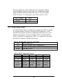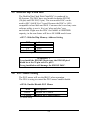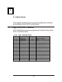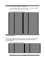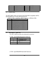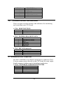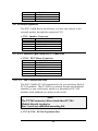
1
SSC-5x86H Ver.C
Super 5x86H Half-sized
Single Board Computer
@Copyright 1996
All Rights Reserved.
Manual second edition Nov.10,1996
The information in this document is subject to change without prior notice
in order to improve reliability, design and function and does not represent
a commitment on the part of the manufacturer.
In no event will the manufacturer be liable for direct, indirect, special,
incidental, or consequential damages arising out of the use or inability to
use the product or documentation, even if advised of the possibility of such
damages.
This document contains proprietary information protected by copyright. All
rights are reserved. No part of this manual may be reproduced by any
mechanical, electronic, or other means in any form without prior written
permission of the manufacturer.
Trademarks
SSC-5x86H is registered trademarks of Acquire Inc., PC/104 is
trademarked of PC/104 Consortium, IBM PC is a registered trademark of
International Business Machines Corporation. Intel is a registered
trademark of Intel Corporation. AMI is registered trademarks of American
Megatrends, Inc. Other product names mentioned herein are used for
identification purposes only and may be trademarks and/or registered
trademarks of their respective companies.
Contents
1. Introduction.................................................................3
1.1
Specifications.........................................................................................4
1.2
What You Have......................................................................................5
2. Installation...................................................................6
2.1
SSC-5x86H Ver.C Layout ......................................................................6
2.2
Jumper Description ................................................................................8
2.3
CPU setting of SSC-5x86H Ver.C ..........................................................9
2.4
Watch-Dog Timer.................................................................................10
2.5
DiskOChip Flash Disk .........................................................................11
2.6
PS/2 Mouse Setting..............................................................................11
3. Connection ................................................................12
3.1
Floppy Disk Drive Connector ...............................................................12
3.2
IDE Disk Drive Connector....................................................................13
3.3
Parallel Port .........................................................................................13
3.4
Serial Ports ..........................................................................................14
3.5
Keyboard Connector.............................................................................14
3.6
External Switches and Indicators ..........................................................15
3.7
External Power Connector ....................................................................15
3.8
External Speaker..................................................................................16
1
3.9
PS/2 Mouse Port .................................................................................16
3.10
PC/104 Connection Bus .......................................................................16
4. AWARD BIOS Setup................................................18
4.1
Getting Start ........................................................................................18
4.2
Standard CMOS Setup .........................................................................20
4.3
BIOS Feature Setup..............................................................................21
4.4
Chipset Feature Setup ..........................................................................22
4.5
Power management Setup.....................................................................23
Appendix A. Watch-Dog Timer.....................................25
2
1
Introduction
Welcome to the SSC-5x86H Super 5x86 Half-sized Single
Board Computer. The SSC-5x86H board is an ISA and
PC/104 form factor board, which comes equipped with high
performance 486DX/DX2/DX4 or the latest Cyrix/AMD 5x86
CPU and advanced high performance multi-mode I/O,
designed for the system manufacturers, integrators, or VARs
that want to provide all the performance, reliability, and
quality at a reasonable price.
An advanced high performance super AT I/O chip UMC
UM8669 is used in the SSC-5x86H board. Both on-chip
UARTs are compatible with the NS16C550. The parallel port
and IDE interface are compatible with IBM PC/AT and XT
architecture's. The UM8669 incorporates sophisticated power
control circuitry(PCC). The PCC supports multiple low power
down modes.
In addition, the SSC-5x86H provides two 72-pin SIMM sockets for
its on-board DRAM. The 72-pin accepts 1MB, 2MB, 4MB, 8MB,
16MB, and 32MB SIMM. So, the total on-board memory can be
configured from 1MB to 64MB.
SSC-5x86H uses the ALI chipset, M1489 and M1487, which
are 100% ISA compatible chipset.
The new Ver.C board have built-in DiskOnChip Flash Disk
Function and ESD +/-15KV protection RS-232 ports. The new
version will only need +5V power supply. It will be more
suitable for embedded application.
3
1.1
Specifications :
The SSC-5x86H Super 5x86 Half-sized Single Board Computer
provides the following specification:
•
CPU : 486SX/DX/DX2/ DX4 or Cyrix/AMD 5x86
•
Bus : ISA bus and PC/104 bus
•
DMA channels : 7
•
Interrupt levels : 15
•
Chipset : M1489 and M1487
•
Real-time clock/calendar : DS-12887 chip and quartz oscillator,
128B CMOS memory, powered by lithium battery for over 10
years of data retention.
•
RAM memory : 1MB to 64MB,EDO and standard DRAM
supported
•
E-IDE hard disk drive interface : up to two PCI Enhance IDE
hard drives.
•
Floppy disk drive interface : two 2.88 MB, 1.44MB, 1.2MB,
720KB, or 360KB floppy disk drives.
•
Two high speed Series ports : NS16C550 compatible UARTs
•
Bi-directional Parallel Port
•
Watch-dog timer : can be set by 1,2,10,20,110 or 220 seconds
period. Reset or NMI was generated when CPU did not
periodically trigger the timer. Your program use hex 043 and 443
to control the watch-dog and generate a system reset.
•
External power connector
•
Keyboard connector
•
Mouse : PS/2 Mouse Port on-board.
•
Power Consumption : +5V @ 1.75A ( 5x86-133, 4MB RAM)
•
Operating Temperature : 0° ~ 60° C ( CPU needs Cooler)
4
1.2
What You Have
In addition to this User's Manual, the SSC-5x86H Ver.C
package includes the following items:
• SSC-5x86H Ver.C Super 5x86 Half-sized SBC
•
Printer Cable
•
FDD/HDD Cable
•
6-pin Mini-Din to 5-pin Din Keyboard Adapter Cable
If any of these items is missing or damaged, contact the
dealer from whom you purchased the product. Save the
shipping materials and carton in case you want to ship or
store the product in the future.
5
2
Installation
This chapter describes how to install the SSC-5x86H. At first,
the layout of SSC-5x86H is shown, and the unpacking
information that you should be careful is described. The
jumpers and switches setting for the SSC-5x86H's
configuration, such as CPU type selection, system clock
setting, and interrupt IRQ setting for serial ports and parallel
port, are also included.
2.1
SSC-5x86H Ver.C Layout
< reference next page >
6
7
2.2 Jumper Description
You can change the SSC-5x86H's configuration by setting jumper
switches on the board. The board's jumpers are preset at the factory.
Under normal circumstances, you should not need to change the
jumper settings.
A jumper switch is closed (sometimes referred to as shorted with
the plastic cap inserted over two pins of the jumper). A jumper is
open with the plastic cap inserted over one or no pin(s) of the
jumper. Figure 2.2 below shows different jumper settings which
will be used in this chapter.
CLOSED
OPEN
1
1
1-2
2-3
1
1
1
2
2
2
3
3
3
1-2
2-3
2-4
Figure 2.2
8
2.3
CPU setting of SSC-5x86H Ver.C
If you want to upgrade the CPU, you must do two things:
1. Set the jumpers for CPU type.
2. Adjust the jumpers setting for CPU speed.
• CPU Type Setting:
CPU Type
JP1
Intel DX4 &E
2-3
* Cyrix 5x86
AMD DX4+
2-3
(SV8B)
Intel DX2/DX4
&EW
SGS
ST486DX4V
ST486DX2V
Cyrix/TI/SGS
2-3
DX2/DX4
AMD DX2/DX4
2-3
(NV8T)
AMD
2-3
DX2+(SV8B)
AM5x86 P75
(133Mhz)
(*) : default setting
ON=CLOSE
JP2
2-3
JP3
3-4
JP4
3-4
JP5
3-4
JP6
OFF
JP7
OFF
JP8
1-2
JP9
ON
2-3
3-4
3-4
3-4
5-6
2-3
2-3
ON
2-3
5-6
5-6
5-6
1-2
1-2
1-2
ON
2-3
OFF
OFF
1-2
OFF
OFF
1-2
OFF
2-3
3-4
3-4
3-4
1-3
5-6
2-3
2-3
ON
OFF=OPEN
JP10 : OPEN
• CPU Clock Setting :
CPU
Clock
25MHz
* 33MHz
40MHz
JP12
JP14
OPEN
OPEN
CLOSE
1-2
1-2
2-3
JP11
1-2
OPEN
CLOSE
OPEN
(*): default setting
Note :
DX2-66/DX4-100/5x86-100 sets CPU Clock - 33Mhz
AMD 5x86 P75(133MHz) sets CPU Clock - 33MHz
DX2-80/DX4-120/5x86-120 sets CPU Clock - 40MHz
• CPU Voltage Selection - 3.3V, or 3.45V
9
JP11
3-4
OPEN
CLOSE
CLOSE
Because right now in the market have several kind of CPUs
using different voltage in core logic. For example the AMD
offers 486DX2-66/80 and DX4-100/120 at 3.3V,Intel offers
DX4-75/100 at 3.3V,and some Cyrix CPU will use 3.45V.
CPU Voltage
* +3.3V
+3.45V
JP13
2-3
1-2
(*) : default setting
2.4 Watch-Dog Timer
The Watch-Dog Timer is enabled by reading port 443H. It should
be triggered before the time-out period ends, otherwise it will
assume the program operation is abnormal and will issue a reset
signal to start again, or activate NMI to CPU. The Watch-Dog
Timer is disable by reading port 043H. See Appendix A for more
detailed description of Watch-Dog Timer.
• JP15 : Watch-Dog Active Type Setting
JP15
DESCRIPTION
*1-2
RESET WHEN WDT TIME-OUT
2-3
ACTIVATE NMI TO CPU WHEN WDT TIME-OUT
OPEN
DISABLE WDT
(*): default setting
• JP16: WDT Time-Out Period
PERIOD
1-2
3-4
1 sec.
OPEN
OPEN
2 sec.
OPEN
OPEN
*10 sec.
OPEN
CLOSE
20 sec.
OPEN
CLOSE
110 sec.
CLOSE
OPEN
220 sec.
CLOSE
OPEN
(*) : default setting
10
5-6
CLOSE
CLOSE
OPEN
OPEN
OPEN
OPEN
7-8
OPEN
CLOSE
OPEN
CLOSE
OPEN
CLOSE
2.5 DiskOnChip™Flash Disk
The DiskOnChip Flash Disk Chip(DOC) is produced by
M-Systems. The DOC have two models in market ED1102
(28-pin) and ED1202(32-pin). The two models DOC can be
used in SSC-5x86H Ver.C board. Because the DOC is 100%
compatible to hard disk and DOS. Customer don’t need any extra
software utility to use it. It is just “plug and play”,easy
and reliable. Right now the DOC is available in 1MB/2MB
capacity, in the near future will have 4/8/16MB model soon.
• JP17 : DiskOnChip Memory Address Setting
JP17
1-2
3-4
* 5-6
Address
D000
D800
E000
(*): default setting
WARNING !!
If you install the ED1102,28-pin type, the ED1102 pin-1
should be at the 32-pin socket’s pin 3.
Wrong installation will damage the ED1102 DOC.
2.6 PS/2 Mouse Setting
The PS/2 mouse will use the IRQ12 when operation.
The JP18 is using to control the PS/2 mouse enable/disable.
• JP18 : Enable/Disable PS/2 Mouse
JP18
OPEN
* CLOSE
Description
Disable PS/2 Mosue
Enable PS/2 Mouse,IRQ12
(*): default setting
11
3
Connection
This chapter describes how to connect peripherals, switches
and indicators to the SSC-5x86H board.
3.1
Floppy Disk Drive Connector
SSC-5x86H board comes equipped with a 34-pin daisy-chain
driver connector cable.
• CN6 : FDC CONNECTOR
PIN NO.
1
3
5
7
9
11
13
15
17
19
21
23
25
27
29
31
33
DESCRIPTION
GROUND
GROUND
GROUND
GROUND
GROUND
GROUND
GROUND
GROUND
GROUND
GROUND
GROUND
GROUND
GROUND
GROUND
GROUND
GROUND
GROUND
PIN NO.
2
4
6
8
10
12
14
16
18
20
22
24
26
28
30
32
34
12
DESCRIPTION
REDUCE WRITE
N/C
N/C
INDEX#
MOTOR ENABLE A#
DRIVE SELECT B#
DRIVE SELECT A#
MOTOR ENABLE B#
DIRECTION#
STEP#
WRITE DATA#
WRITE GATE#
TRACK 0#
WRITE PROTECT#
READ DATA#
SIDE 1 SELECT#
DISK CHANGE#
3.2
PCI E-IDE Disk Drive Connector
You can attach two IDE( Integrated Device Electronics) hard disk
drives to the SSC-5x86H internal controller.
• CN1: IDE Interface Connector
PIN NO.
1
3
5
7
9
11
13
15
17
19
21
23
25
27
29
31
33
35
37
39
DESCRIPTION
RESET#
DATA 7
DATA 6
DATA 5
DATA 4
DATA 3
DATA 2
DATA 1
DATA 0
GROUND
N/C
IOW#
IOR#
N/C
N/C
INTERRUPT
SA1
SA0
HDC CS0#
HDD ACTIVE#
PIN NO.
2
4
6
8
10
12
14
16
18
20
22
24
26
28
30
32
34
36
38
40
DESCRIPTION
GROUND
DATA 8
DATA 9
DATA 10
DATA 11
DATA 12
DATA 13
DATA 14
DATA 15
N/C
GROUND
GROUND
GROUND
BALE - DEFAULT
GROUND - DEFAULT
IOCS16#-DEFAULT
N/C
SA2
HDC CS1#
GROUND
3.3 Parallel Port
This port is usually connected to a printer, The SSC-5x86H includes
an on-board parallel port, accessed through a 26-pin flat-cable
connector CN9.
• CN9 : Parallel Port Connector
PIN NO.
1
3
5
7
9
11
13
15
DESCRIPTION
STROBE#
DATA 1
DATA 3
DATA 5
DATA 7
BUSY
PRINTER SELECT
ERROR#
PIN NO.
2
4
6
8
10
12
14
16
13
DESCRIPTION
DATA 0
DATA 2
DATA 4
DATA 6
ACKNOWLEDGE
PAPER EMPTY
AUTO FORM FEED #
INITIALIZE
17
19
21
23
25
3.4
PRINTER SELECT LN#
GROUND
GROUND
IOW#
GROUND
18
20
22
24
GROUND
GROUND
GROUND
GROUND
Serial Ports
The SSC-5x86H offers two high speed NS16C550 compatible UARTs
with Read/Receive 16 byte FIFO serial ports.
• CN12 & CN14 : Serial Port DB-9 Connector( ACE0 & ACE1)
PIN NO.
1
2
3
4
5
6
7
8
9
3.5
DESCRIPTION
DATA CARRIER DETECT (DCD)
RECEIVE DATA
(RXD)
TRANSMIT DATA
(TXD)
DATA TERMINAL READY (DTR)
GROUND
(GND)
DATA SET READY
(DSR)
REQUEST TO SEND
(RTS)
CLEAR TO SEND
(CTS)
RING INDICATOR
(RI)
Keyboard Connector
The SSC-5x86H provides two keyboard connectors.
• CN10 : 5-pin Header Keyboard Connector
PIN NO.
1
2
3
4
5
DESCRIPTION
KEYBOARD CLOCK
KEYBOARD DATA
N/C
GROUND
+5V
• CN15 : 6-pin Mini-DIN Keyboard Connector
14
PIN NO.
1
2
3
4
5
6
3.6
DESCRIPTION
KEYBOARD DATA
N/C
GROUND
+5V
KEYBOARD CLOCK
N/C
External Switches and Indicators
There are many external switches and indicators for monitoring
and controlling your CPU board.
• CN4 : RESET BUTTON
PIN NO.
1
2
DESCRIPTION
EXTERNAL RESET
GROUND
• CN2 : POWER LED & KEYLOCK
PIN NO.
1
2
3
4
5
DESCRIPTION
POWER LED ANODE
KEY
GROUND
KEYLOCK
GROUND
• CN5 : IDE LED connector
PIN-NO
1
2
DESCRIPTION
+5V
HDD ACTIVE#
3.7 External Power Connector
The SSC-5x86H has an on-board external power connector CN11.
You can connect power directly to the CPU board for some singleboard-computer( without passive backplane) application.
• CN11 : EXTERNAL POWER CONNECTOR
PIN NO.
1
2
3
4
DESCRIPTION
+5V
+12V
-12V
GROUND
15
5
6
7
8
GROUND
-5V
+12V
+5V
3.8 External Speaker
The SSC-5x86H has its own buzzer, you also can connect to the
external speaker through the connector CN3.
• CN3 : Speaker Connector
PIN NO.
1
2
3
4
DESCRIPTION
SPEAKER SIGNAL
NC
GROUND
+5V
3.9 PS/2 Mouse 6-pin Mini-DIN Connector
• CN13 : PS/2 Mouse Connector
PIN NO.
1
2
3
4
5
6
DESCRIPTION
MS DATA
NC
GROUND
+5V
KBT1
NC
3.10 PC/104 Connection Bus
The SSC-5x86H's PC/104 expansion bus let you attach any kind of
PC/104 modules. The PC/104 bus is already become the industrial
standard, so you could easily install over thousands of PC/104
modules from hundreds of venders in the world.
Note :
The PC/104 connector allows stack-thru PC/104
Module directly to plug in.
Don‘t need any additional mounting Kit.
• CN7 & CN8 : PC/104 Expansion Bus
16
( CN7 = 64-pin female connector;
CN8 = 40-pin female connector.)
Pin
NO.
J1 / P1
Row A
J1 / P1
Row B
J2 / P2
Row C
J2 / P2
Row D
0
1
-IOCHECK*
--
0V
SBHE*
0V
MEMSC16*
2
3
4
5
6
7
8
9
10
11
12
13
14
15
16
17
18
19
20
21
22
23
24
25
26
27
28
29
30
31
32
SD7
SD6
SD5
SD4
SD3
SD2
SD1
SD0
IOCHRDY
AEN
AS19
SA18
SA17
SA16
SA15
SA14
SA13
SA12
SA11
AS10
SA9
SA8
SA7
SA6
SA5
SA4
SA3
SA2
SA1
SA0
0V
LA23
LA22
LA21
LA20
LA19
LA18
LA17
MEMR*
MEMW*
SD8
SD9
SD10
SD11
SD12
SD13
SD14
SD15
(KEY)
--------------
IOSC16*
IRQ10
IRQ11
IRQ12
IRQ15
IRQ14
DACK0*
DRQ0
DACK5*
DRQ5
DACK6*
DRQ6
DACK7*
DRQ7
+5V
MASTER*
0V
0V
--------------
0V
RESETDRV
+5V
IRQ9
-5V
DRQ2
-12V
NOWS*
+12V
(KEY)
SMEMW*
SMEMR*
IOW*
IOR*
DACK3*
DRQ3
DACK1*
DRQ1
REFRESH*
SYSCLK
IRQ7
IRQ6
IRQ5
IRQ4
IRQ3
DACK2*
TC
BALE
+5V
OSC
0V
0V
NOTES:
1. Rows C and D are not used on 8-bit modules.
2. P2 has two connector options with differing physical pinout orientation.
3. B10 and C19 are key locations.
4. Signal timing and function are as specified in p996.
5. Signal source/sink current differ from P996 values.
17
4
AWARD BIOS Setup
The SSC-5x86H uses the AWARD PCI/ISA BIOS for system
configuration. The AWARD BIOS setup program is designed to
provide maximum flexibility in configuring the system by offering
various options which may be selected for end-user requirements.
This chapter is written to assist you in the proper usage of these
features.
4.1 Getting Start
When powered on the system, the BIOS will enter the Power-OnSelf-Test routines. These routines will be executed for System Test
and Initialization and System Configuration Verification. After the
POST routines are completed, the following message appears :
" Press DEL to enter setup"
To access AWARD PCI/ISA BIOS Setup program, press <Del> key.
The following screen will be displayed at this time.
18
19
4.2 Standard CMOS Setup
The Standard CMOS Setup is used for basic system hardware
configuration. Every time when you change any hardware
configuration,for example memory size,you have to modify this
setup again. Please refer the following screen for this setup.
Mode Setting for >528MB IDE HDD
When the IDE hard disk drive you are using is larger than
528MB,please set the HDD mode to LBA mode.
Note : Setting incorrect drive mode may make the drive working
improperly.
20
4.3 BIOS Features Setup
This setup is designed for customer‘s tuning best performance
of the SSC-5x86H board. As for normal operation customers don‘t
have to change any default setting.The default setting is pre-setted
for most reliable operation.
Virus Waring :
Enable - Will halt system when any attempt to
write to boot sector or patition table of hard disk.
Memory Parity Check :
Disable - Will not check the DRAM module‘s parity. Right now
almost 72-pin SIMM DRAM did not have parity function.
Video BIOS Shadow :
Enable - Will increase the video speed.
C8000-CFFFF,D0000-D7FFF,& D8000-DFFFF Shadow :
When the installed add-on card‘s ROM address is as
21
above address,you could enable the shadow to get higher
operation performance.When you enable the shadow
function,it will also reduce the memory available by between
640KB and 1024KB.
4.4 Chipset Features Setup
This setup functions are almostly working for ChipSet(ALI M1489 and
M1487). These options are used to change the ChipSet‘s registers. Please
carefully change any default setting ,otherwise the system could be running
un-stable.
Auto Configuration :
Enable : The BIOS will configure the ChipSet features
automatically when boot up the system.
Disable : The BIOS will allow customer to change the setting
22
on the screen.
Parallel Port Mode : SPP(default),EPP,ECP,ECP+EPP
Onboard FDC Controller : Enabled(default),Disabled
Onboard Serial Port 1 :
COM1/3F8(default),COM2/2F8,COM3/3E8,COM4/2E8
Disabled
Onboard Serial Port 2 :
COM2/2F8(default),COM3/3F8,COM4/2E8,Diabled
COM1/3F8
Onboard Parallel Port :
378H/IRQ7(default),278H/IRQ5,3BCH/IRQ7,Disabled
4.5 Power Management Setup
Power Management Setup help user handles the SSC-5x86H
board‘s “green” function. The features will shut down the video
display and hard disk to save energy.
23
Power Management :
This is the master control of all power management functions.
The default setting is “disable” for general application.
User Defined : Allows user to set any power saving options.
Min. Saving : System enters power saving mode after
1 hour no activity.
Max. Saving : System enters power saving mode after
5 seconds no activity.
PM Control by APM :
No - Default setting
Yes - System BIOS will wait for APM prompt before it enters
any power management mode.
Note : APM Mode :
This mode is using for DOS 6.0 or higher version with
the driver POWER.EXE. The driver should be loaded
at system power-on by CONFIG.SYS file. POWER.EXE
will monitor the system status thru the BIOS APM
interface.
Video Off Option :
Susp,Stby ¡ ÷
Off - Screen Off when system in Suspend or
Standby mode.
Susp ¡ ÷
Off - Screen Off when system in Suspend mode.
All Modes ¡ ÷
Off - Screen Off when system in Suspend,
Standby,or Doze mode.
Alway On - System BIOS will never turn off the screen.
Video Off Method :
Blank Screen : When BIOS do the video off the screen
will be blank.
V/H Sync, + Blank : When BIOS do the video off,BIOS will turn
of the V-sync & H-sync signals from VGA
24
card and also let the screen blank.
PM Timers :
User can set the HDD Power Down,Doze Mode,Standby Mode,
and Suspend Mode‘s time out period. The system will be
recovered when the system is re-activity.
PM Events :
If there is any activity occured on the list of the group,the
system will wake up. You can set the IRQ1,IRQ3-15
individually in the list.
Appendix A. Watch-Dog Timer
The Watch-Dog Timer is provided to ensure that standalone
systems can always recover from catastrophic conditions that
caused the CPU to crash. This condition may have occurred by
external EMI or a software bug. When the CPU stops working
correctly, hardware on the board will either perform a hardware
reset (cold boot) or a non-maskable interrupt (NMI) to bring the
system back to a known state.
The Watch-Dog Timer is controlled by two I/O ports.
443
(hex)
043
(hex)
Read
Enable the refresh the Watch-Dog Timer.
Read
Disable the Watch-Dog Timer.
To enable the Watch-Dog Timer, a read from I/O port 443H must
be performed. This will enable and activate the countdown timer
which will eventually time out and either reset the CPU or cause an
NMI depending on the setting of JP15. To ensure that this reset
condition does not occur, the Watch-Dog Timer must be
periodically refreshed by reading the same I/O port 433H. This
must be done within the time out period that is selected by jumper
group JP16.
A tolerance of at least 30% must be maintained to avoid unknown
routines within the operating system (DOS), such as disk I/O that
can be very time consuming. Therefore if the time out period has
25
been set to 10 seconds, the I/O port 443H must be read within 7
seconds.
Note: when exiting a program it is necessary to disable the WatchDog Timer, otherwise the system will reset.
26
10
11
20
30
40
50
60
70
80
90
REM EXAMPLE PROGRAM
REM WATCH-DOG TIMER == WDT
GOSUB 5000 REM ENABLE AND REFRESH THE WDT
GOSUB 1000 REM TASK 1, 2 SECS
GOSUB 5000 REFRESH THE WDT
GOSUB 2000 REM TASK 2, 3 SECS
GOSUB 6000 REM DISABLE THE WDT
GOSUB 3000 REM TASK 3, 5 SECS
GOSUB 5000 REM ENABLE AND REFRESH THE WDT
GOTO 30
1000
REM SUBROUTINE #1
2 SECONDS TO COMPLETE
RETURN
1070
2000
2070
REM SUBROUTINE #2
3 SECONDS TO COMPLETE
RETURN
5000
5010
5020
REM SUBROUTINE TO ENABLE AND RESET WDT
X = INP( &H443) REM ENABLE AND REFRESH TIMER
RETURN
6000
6010
6020
REM SUBROUTINE TO DISABLE THE WDT
X = INP( &H43) REM RESET WDT
RETURN
27