1
@ Copyright 1998
All Right Reserved
The information in this document is subject to change without prior notice
in order to improve reliability, design and function and does not represent
commitment on the part of the manufacturer.
In no event will the manufacturer be liable for direct, indirect, special,
incidental, or consequential damages arising out of the use or the
possibility of such damages.
This document contains proprietary information protected by copyright.
All rights are reserved. No part of this manual may be reproduced by any
mechanical, electronic, or other means in any form without prior written
permission of the manufacturer.
Acknowledgments
All trademarks and registered trademarks mentioned herein are the
property of their respective owners.
Nov., 1998
Printed in Taiwan
Version A
Check List
Before getting started, please check if the 486 All-in-One Single Board
Computer package includes the following items:
!
486 All-in-One board x 1pc
!
VGA Driver & Utility diskette x 4 pcs
!
Updating BIOS Utility diskette x 1 pcs
!
Keyboard adapter x 1pc
!
FDD cable x 1 pc
!
HDD cable x 1 pc
!
COM2 and Printer extension cables with bracket x 1pc
!
User’s manual x 1pc
Table of Contents
Chapter 1.
Introduction
Specifications………………………………………… 1-1
Chapter 2.
Jumpers and Connectors
Jumpers setting……………………………………… 2-2
Connectors……………………………………………. 2-4
Chapter 3.
Installations
Installing the SIMMs.………………………………..
3-1
Completing the Installation…………………………. 3-1
Chapter 4.
Award BIOS Setup
Entering Setup……………………………………….
4-1
The Main Menu………………………………………
4-4
Standard CMOS Setup……………………………… 4-7
BIOS Features Setup………………………………… 4-11
Chipset Features Setup…………………………….. 4-16
Power Management Setup…………………………
4-17
PCI Configuration Setup……………………………. 4-22
Password Setting……………………………………. 4-25
IDE Auto Detection………………………………….. 4-26
Hard Disk Low Level Format Utility……………….
4-29
Power on Boot……………………………………….. 4-31
BIOS Reference - POST Codes……………………. 4-31
Chapter 5.
Display
Drivers and Utilities
5.1.1 Microsoft Windows 3.1………………………..
5-1
5.1.2 MS Windows 95/NT Mode Driver Install ……
5-2
5.1.3 MS Windows 95 Refresh Rate Utility ………
5-2
Panel Support
5.2.1 For 40K BIOS……………………………………. 5-3
5.2.2 For 44K BIOS……………………………………. 5-4
Video Modes………………………………………..
5-6
Appendix
A. Watchdog Timer
Appendix
B. Connectors’ Pin Assignment
Appendix
C. Installing Disk On Chip
Appendix
D. Updating BIOS
Appendix
E.
I/O address map
Appendix
F.
memory address map
Appendix
G.
Mechanical drawing
Chapter 1
Introduction
The 486 all-in-One Single Board Computer comes equipped with either
Intel / AMD / Cyrix / SGS Thomson 80486 CPU series. Also included onboard are CHIPS 65550 VGA GUI Accelerator controller, one socket for
Flash Disk, two serial RS-232 ports (one for RS232/RS422/RS485),
enhanced bi-directional parallel port, PCI enhanced IDE hard disk drive
interface, floppy disk controller and watchdog timer. The 486 All-in-One
board industrial-grade construction ensures continuous, reliable operation
in harsh industrial environments.
Its video section features the ability to control most EL, mono/color STN
and TFT flat panel display as well as standard VGA. Equipped with 1MB of
EDO DRAM, up to 2MB EDO DRAM (optional). The CHIPS 65550 can
display in 640x480 resolution on commonly used flat panels and true color
displays on CRT’s.
You can also use this reliable 486 All-in-One to transform any system into
a 32-bit 486 compatible computer. Its highly compact form and numerous
features make it an ideal cost/performance solution for high-end
commercial and industrial applications when fast CPU speed and low
mean-time-to-repair are critical.
1.1 Specifications
. Bus Type:
ISA bus - 98 pin for 16 bit ISA bus
. CPU:
On board equipped with SQFP CPU, speed up to AMD 5x86-133.
. Cache:
nd
256KB/512KB 2 level cache memory
. Memory:
Supports FPM/EDO DRAM module.
Supports on board 4 MB DRAM and one 72-pin SIMM sockets,
Or two 72-pin SIMM sockets accept 1,2,4,8,16 or 32 MB SIMM
module.
. Chipset:
System Chipset: ALI M1487/M1489
I/O Chipset: SMC 37C669
. Real Time Clock:
SGS M48T86 PCI (or compatible) with lithium battery backup for 10
years
of data retention
. Display:
-Chipset: C&T 65550 PCI local bus flat-panel with Windows
accelerator
and Video play back
- Display memory: on board EDO DRAM 1MB up to 2MB
- Display resolution:
Supports Flat-panel resolutions up to 640x480, 800x600, 1024x768,
1280x1024
Supports non-interlace CRT monitors, 1024x768 64K colors
- Display connector: DB-15 VGA connector for CRT monitor and 2x22
pin
header for Flat-panel
- Support 3.3V and 5V Flat-panel
. S.S.D.:
Socket for M-system Disk on Chip
. IDE:
Supports up to two, PCI mode 4 enhance IDE hard disk interface
. Floppy:
Supports up to two floppy disk drivers, 3.5” and/or 5.25”
. Parallel Port:
Enhanced Bi-directional EPP/ECP parallel port
. Serial port:
One RS232 port with 16C550 UART
One RS232/422/485 port with 16C550 UART
. Watchdog Timer:
Can generate a system RESET, The timer interval is 0 ~ 63 sec (14
level)
. Keyboard Connector:
One 6 pin Mini_Din connector is located on the mounting bracket
One pin header connector for external keyboard adapter
. Expansion Bus:
A 16 Bit PC104 connector for expansion modules
. Power Supply Voltage:
Single power +5V/2.5A, 8_pin external power connector
. Operating Temperature:
32° to 140° F (0° to 60° C)
. Board Size:
185mm X 122mm
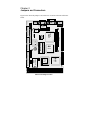
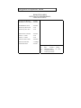
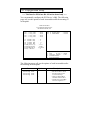
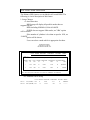
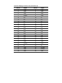
Chapter 2
Jumpers and Connectors
!!!
"##$
8
PRN
MOUSE
VGA
1
J5
JP5
8
7
PC104
C0
D0
DiskOnChip
T65550
CHIPS
K/B
JP2
ALI
M1487
JP3
1
SGS
JP1
M48T86PCI
3
18
10
IDE 9
39
40
SIMM2SIMM1
M1489
NEAT- 470
ALI
-
ADVANCED
MICRO
DEVICES
AM486DX5-133
1
2
17
J1
B1
A1
J3
FDC
1
2
2
1
1
2
26
43
44
25
1
2
3
1
18
84
JP4
34
2
17
33
1
2
SMC
2
2
1
BIOS
FD37C669
1
1
9
10
JP6
1
2
COM2
J4
COM1
1
KB1
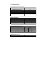
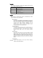
2.1 Jumpers Setting
Speaker/Keylock/Reset/Turbo/LED (J1)
J1
1-3
1-7
2-6
8-10
11-12
13-14
15-16
17-18
Internal buzzer
External speaker (remove 1-3)
Power LED, Pin 2+, Pin6Keylock
System reset switch
Turbo Switch
Turbo LED, Pin16+, Pin15HDD LED, Pin18+, Pin17-
External keyboard (J5)
J5
1
2
3
4
5
Keyboard clock
Keyboard data
No Connect
Keyboard ground
Keyboard power
M-System Address Select (JP1, 1-6)
CC00-CDFF
D000-D1FF
D800-D9FF
E000-E1FF
1-2
open
open
open
open
JP1
3-4
close
open
close
open
Watchdog Timer (JP1, 7-8)
Watchdog time out gen. system reset
JP1
7-8
5-6
close
close
open
open
CMOS clear (JP1, 9-10)
Closed this jumper, power on system
1minute then power off,
Remove this jumper
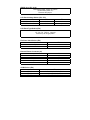
LCD Panel Voltage Select (JP3, JP5)
JP3
3.3V Panel Interface
1-2
5.0V Panel Interface
2-3
JP5
close
open
LCD Panel Type Select (JP6)
1-2, 3-4, 5-6, 7-8 four jumpers
to select up to 16-type panel
Flat Panel Clock Select (JP2)
Invert Clock
Normal Clock
JP2
1-2
2-3
External Power Connector (J4)
+5V
Ground
+12V
-12V
-5V
J4
1,8
4,5
2,7
3
6
COM2 Select (JP4)
RS232
RS422
RS485
JP4
3-5, 4-6, 9-11, 10-12, 17-18
1-3, 2-4, 7-9, 8-10, 15-16
1-3, 2-4, 7-9, 8-10, 13-14
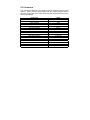
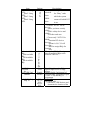
2.2 Connectors
The connectors allow the CPU card to connect with other parts of the
system. Some problems encountered with your system may be caused
by loose or improper connections. Ensure that all connectors are in place
and firmly attached.
Component
HDD (IDE) connector
FDD connector
VGA connector
Flat panel connector
Parallel port
PC/104 connector
Keyboard connectors
PS/2 Mouse connectors
Reset switch connector
External speaker connector
HDD LED connector
Turbo switch connector
Turbo LED connector
SBC power connector
RS-232 serial port
RS422,485 serial port
CMOS RAM clear
Label
IDE
FDC
VGA
J3
PRN
PC104
KB
mouse
J1 (11-12)
J1 (1-7)
J1 (17-18)
J1 (13-14)
J1 (15-16)
J4
COM1, COM2
COM2
JP1(9-10)
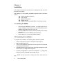
Chapter 3
Installation
This chapter describes the procedures for installing the 486 All-in-One
board into your system.
The following
system:
"
"
"
"
"
is a list of typical peripherals required to build a minimum
Passive backplane (optional)
Power supply
IBM PC/AT keyboard
Display monitor
Floppy or hard disk with MS-DOS or Flash Disk emulator
3.1 Installing the SIMMs
Insert the first SIMM edge connector at a slight angle into the
socket of SIMM 1 close to the center of the board. Note that the
SIMM is keyed and will only go in one way.
Push the SIMM back into the connector carefully until it snaps
into place.
Check to make sure the SIMM is inserted securely.
Repeat Steps 1-3 for remaining SIMM in SIMM 2.
3.2 Completing the Installation
To complete the installation, the following steps should be followed:
Set the configuration jumpers in accordance with Chapter 2.
Make sure the power is off.
If use PC/104 peripherals, install the PC/104 card into PC/104 socket
of the 486 All-in-One board.
Install the 486 All-in-One board into an ISA passive backplane or just
stand it alone as a Single Board Computer.
Connect the applicable I/O cables and peripherals, i.e. floppy disk,
hard disk, monitor, keyboard, power supply and etc.
NOTE: the color of pin one is usually red or blue, while others are
gray
6.
Turn on the power.
!"#$$#%%&'($$&#
$&(&)$"*)$(*&'#$&+,$)%&&($&
$& "$$)"* ! -.! !/ & $$ $ $
$$#%&($&$%&$#&+
0&&$*&(%#$%12(($)
&)&#$&$$#%+,&$)$&$$#%$&
%&&$*&(%#$$"&('%%
")$$"&$$&(&$*#'$0,-0&
,$/%12)&(#$&#)%1.$2
1$213*2)+
, 34,3 3,50 3 3 , 0 3 1., 66,
3.2 1362738
$('%%"&)&#%&)&#$$&
$$#%$$$)$($&$)'")$#'$$
4 & %' $ 9 33,9 "#$$& & $ )$( *+ 8&#
() & $$ ") (#$&#) %' 1.$2 1$2 1$2 )+ )&# & &$ % $ ) $ $ *&*$ $(
$ )$( & &$ "&&$ & (' %) )&#'"$&
0 3 1:2 , .4,453 1., 66,3.2 1362,34,3 3,50
5%&
&&
6$&
'$&
3*)
!&;$&%;&#$(
!&;$&<$$(
!&;$&$$($$
!&;$&$$($'$
! !# =#$ &$ ; *' $&
.!
$$# 0' $#% !# %$& 0' $#%
!#3<$*#$%'$#$&!!#
0'5% >?@ *$#(*;#&(*'
)
0'
*$#(*;#&(*'
>−>)
:)
%&)&$$#0'$#%!#
%$&0'$#%!#
-$/A
.' *&& &( $&$ : *&&+ A $& *$
)
*&&&-$/A$&*$*&&"*
B)
;
)
;
C)
$& $ %;&# .! ;# &( .!
&)&%$&0'$#%!#
)
6& $ #$ .! ;# &( #$
$"&)&%$&0'$#%!#
D)
6&$$#%#$&)&%$&0'$#%
!#
)
;
E)
;
:F)
;$.!*'&)&!!#
, & *%$& & $ ''$ $#% #*$& %)$$"&$$&(&$*+
0 : $& %&% #% ( % & $$ *" $
%%&%$ ) $& # $ %&" *$& & $
''$ $(+ ,& <$ $ % G& % 1:2 &
13*2+
*)&#$.!$#%5$$)$!!#
%% & $ *+ , ! !# & )&# $& *$
&(;$#%#*$&$&<$*&*+5&)
$&*$(&'$$(%13$2$&**%$&$$
#"(#+
!"
&'()#*!"#" +
↑↓→← #$#""#%
,-!."/0 -(12#3$34
!%#("#
(45!67+#
$.!$#%
, $#% %' *# $ $( $ *&(%$"
+ 0'D$&0':F&$+
$#$#%
, $#% %' *# $ $( & %*
*$#+0'::$&0':C&$+
, $#% %' *# $ $( & *%$ %*
$#+0':&$+
, *$'&) $( & (#* %& *&#(%$& &
$)$(
$*$'$$("&+#$;#"+
0':E
$&0'AB&$+
,*$'&)%*$$#%&0.$;*
&H+0'A&$+
, #$ ; " $ ") $ (#*$# %$$$'*%&;$((#(I#($&
)&#)$($&&%$+
.%$ #$ #*$& *$ $ ;# I# ") $
)$(&$(<(#(%&(*+
.' $ & " %&+ $ & )&# $& ($
**$&$)$($#%&J#$$&$#%+0'AD
&$+
!"
#
#$&($*) $*$ *&'# %($+ 0'A
$&0'BF&$+
"
,$&&;&($#$$)+0'
B:$&0'BA&$+
$%
;$.!;#*'$&.!<$$#%+
!%
"&$.!;#*'<$$#%+
, $( $ .! $#% !# ; $& :F
*$'&+ 3* *$'&) *# & & & (& $ &
$#%$(+5$&)$&''$$$($#
$10'5%2&10'2)$&*$$;#)&#$&*
$(+
("#,%%5577/ #8(1 &9 &::;
!%#,--%%/&9<0''
= 4!)# ' ' ' ' ' "3
4!)# ' ' ' ' ' "3
4!)#
&>>9<!1
4!)#31# (##%347 ?>'@
!5#3 *"#15#5#%347 9&A>>@
"-#4#%347 9;>@
($"1
$$4434 3"($#%347 90A?;@
!" ↑↓→←#$#""#% BC35!.7
& #$+ ,-!."/0-(12#3$34
, $ &($ 1)2 1$2 1(&$2 1)2+ 0
1B2$&&$*+
)
$
(&$
)
, ) & &( # $& $ $( ") $
&)
,$ &(: $& B:-& $ (<(#(& $
(&$/*")")$#(*#*$&)
,(&$K$&#'*+
,)&(:EFF$&#'AFEE
&
, $( &($ 1 1(#$2 1*&2+ , $( **#$ " & $ A&# ($)$( *&*+ &
<(%:%+(+:BLFFLFF+
''
,*$'&) $$ $)%& $* $$ "
$$*&(%#$+,C%$)%
# " $)% & 3* 3 + ,)% : $& ,)%
C%+,)%5#"+
0 0'5%1?2 & 0'1−2 $& *$ #(" $)% & $)% $ #(" % 13$2+ 4&$ $$ $
%**$& & )&# ; (#$ ($* $ $ ; $"+
, &$ & %&%) )&# $ (%&%
&($&&$*$'&)+$$)%&)&#;
&$($*&$)&#*#,)%5$&)&#
&;$)%(#)+
)&# *$ ,)% 5 )&# " $& $ $
&($& & $ &&' $(+ 3$ $ &($&
*$)&($)"&%13$2+,&($&
&# " %&; $ &*#($$& &( )&# ;&&$)$((#*$#+
$ *&$& & $* 3 $ *$& ">,)%:@+
$*&$&&$*.$*$&
">4&@+
)&#*$,803>#$&@#$&$*$$M
. !
;$0,$'&'$3&M.
!+
4!)#"7+#
1 %D#43.7$!15#4
1 %D#43.-#(5
E4!"#+4#3%
=
$(15!12F31#
1 %D#43.#"34
35#"7+#
&$ " $ *$ 443 %
13$2+
(' '
, *$'&) $ $ $)% & &%%) ; &
;$$"$$*&(%#$+
4&
BF7C+AC
:+A! C+AC
DAF7 B+C
:+! B+C
A+
! B+C
4&&%%);$
C: * 0.$)% $ ;N BF &")$
*%*$)
C: * ,$)% '$) ;N :+A
('")$*%*$)
B:A * &#" ;N DAF &")$
*%*$)
B:A * &#" ;N :+ ('")$
*%*$)
B:A * &#" ;N A+
('")$
*%*$)
)
, *$'&) *$ $ $)% & %$ # & $ %()
)$( (&$& $$ (#$ ($* )&# ;& %) * (&$&+$&#'*&)(&$&#%%&$)&#&&$
;$&*$$$)%$#%+
8&#;$&)$&"&&$#%$)$(L
G )&# ; %() (&&*&( *&)$*$&&$;&$)%>!&@+
G )&# ; (&&*&( %() *&)$*$&&$;&$)%@!&&*&(
(&@+
3
"$
.
F
!4
3* %* %$;& %* )+
&33&0(&$&%$+
G$&#$*&$&&)$(
.&& %* %$ %& #% F *&#(
(&
!&&*&( %$ *# ' &#$&
(&&*&(%$
!
,*$'&)$($$*&(%#$$&%
&$*$#'%&#%+
$$#4434
3#4434
$$ "@#7D3(45
$$ "!6#""#
$$ "!6@#7
-#7"#%D33"E!$$13"D#"3++#5.34(17#4434"-("%(7D#5#"#"#5
-#1#)#4"-#5#"#"(131C.("($#4434"-#7"#%E!$$D#"3++#5
(1573 E!$$D#+43%+"#5
-# 7"#% D33" E!$$ 13" D# "3++#5 .34 ( 6#7D3(45 #4434G !" E!$$ D#
"3++#5.34($$3"-#4#4434
-#7"#%D33"E!$$13"D#"3++#5.34(5!6#4434G!"E!$$D#"3++#5
.34($$3"-#4#4434
-#7"#%D33"E!$$13"D#"3++#5.34(6#7D3(45345!6#4434G!"E!$$
D#"3++#5.34($$3"-#4#4434
'
, *$'&) %)&) * $( ") 0,
-0&,$/&$+
!(&)
, 0, & $ $( $ (&#$ &
"-&*&;$&/((&)$$ )$(+
, ;# & $ " ((&) $)%*) C:A7 &
)$( $ C:A7 ((&) $ & $
(&$"& & F7 & )$( $ F7 & (&
((&)$&$(&$"&+
3<$!(&)
, $( & (#* <$ ((&) %$#'$0,+,$(&#$&((&)
&*$ ")& :! $ .05 ((&) (%+
$!(&)
,$&$((&)&*$$F7$&:FA7
%*+,$((&)$$*"#&
$%%*$&+#$$&&;*
; $& % (#* " ((&) &
%%*$&%&'(+!&$#&$&
!+
,&$!(&)
)$( $&$ ((&) $ #( & "* ((&)
<$
((&)&$((&)+
!4 (41!12
1"#41($(-#
*"#41($(-#
!63E#41#$.#"
33"#H #1#
E(+$3++74!)#
33"+$3++7##6
33"+ %36"(" 33"+7"#%+##5
("#
0'+"!31
7+#%("!("##""!12
7+#%("!("#,-(4#/
7+#%("!#$(7,#/
# 4!"7+"!31
($#""#133+
#$#".34
I?>
!(D$#5
!5#3 -(53E 1(D$#5
1(D$#5
;'''C -(53E !(D$#5
1(D$#5
''''CA -(53E !(D$#5
!(D$#5
;'''C -(53E !(D$#5
!(D$#5
1(D$#5
1
!2 ("
!(D$#5
!" ↑↓→←#$#""#%
?
& #$+ BC 35!.7
0<'
< $5($ # ,-!."/03$34
#" +
? 3(5#.( $"
!(D$#
A 3(5#" +#.( $"
31C0
)*
,*$'&)&$*+#'$$)$(
"&&$ #% ) $$(%$ $& $ $& $ "&&$ *$& & %$$&
$" & $ ; $ $ )$( $
&&'&('%%$($()&#*
#$;#%&'($&&*$$%&"(+
OG 44O
"&&$*$&$&"(&
,)%989$&**%$$&949$&"&$$
&$*+
3" *$;$ #$&($*) & $$ $ ' ('
%% $ $ )$( "&&$ #% $ )
$$(%$ $& ** $ "&&$ *$& & %$$&$"+
" 4& ' (' %% $ )
$$(%$ $& ** $ "&&$ *$& & %$$&$"+
4&$L !) '&$* %&'( * $$(%$ $&
** $ "&&$ *$& $" * *# $ "&; '
('+ )&# " #' #* %&'( *&(("#0&$*$&$+
#!%#
,$&*$'&%#%((&)**+,#$;#
3"+ )&# .05 & &$ ; $ .* $ $
$(>.05$.*@&$"&+
3"
"
3"**
"**
+#,&
, *$'&) % #% 0& ,$ -0,/ $ )&#
%&&$*&(%#$+$$$&3"&$
&%&(**$(#'0,+
3"
"
3"I#*0,
4&(0,
-#
,*$'&)$(*;*&(%#$*$&
$ &%$' )$( -++ /+ %$& $( L -:/
.. ! -A/ . !. -B/ . -/ .. -C/
..-/.&)-D/..-
/..+#$;#
P.. !H+
.. )$( $ * & ; $
!
. !&%%);+
.. )$($*&&%%);$
;.
.',
#' 0, $( $ &%%) ;
$F&
F$*+BF7$)%F$*DAF7
:+A!:+!
F$*+
3" *&&%%);$&$(
$ F & F $*+ 4&$ $$ * &$ $
&( DAF7 :+A! & :+! ; $)% $) F$*+
" &$ * & $ $)% & &%%) ; ") $* #("+ 4&$ $$ $ &$ "
)'('$;$BF7+
/#,
, & )&# $& $( $ #$ $$ & #(*
)%+)#$$)$("&&$#%$4#(6&*&+
7)%#(")
7)%&)
'
$ *$ $ #$ )$( % $ % $$ $ )$(
#(($)$%&#%+
'
6&
$$%$&'
$$%$&&
(01
,$) & )&# $& *$& $ $ AF +
,$AF;*#$&((&)"&;:!+
$)$$AF;%&$)"&+
,&) )"& $ %&; $ #%%&$ $ (&
*&((& (#* $ & )$( *%$ $& %&;
#%%&$&$AF+
4&(
$
)"&
*%$
&'#2
, $( $ $)%($* $ $& " #+ G
"*&$#)&'&)&)&#)"&
'$&)&$*+&$&$&)
%&$$$$)&+G$$)%($*$"
$%&$"&"#$$$$(&($
$)$&$"'$%&$$$$)
" % %$)+ & <(% )&# &# #
#*$#$&**$*#&(&;($$&)+
3"
3"$)%($*$
" "$)%($*$
&'#23#4
G $ $)%($* $ " $ *$& & )&#
*$$$$*$)**$+
**$%*&
**$%*&
:F
:F**$%*&
:A
:A**$%*&
:C
:C**$%*&
AF
AF**$%*&
A
A**$%*&
BF
BF**$%*&
&'# '3#4
G$$)%($*$"$*$&&)&#$&
*$$)"$$)$%
$**$&"'+
ACF
CFF
DCF
:FFF
ACF (*
CFF (*
DCF (*
:FFF (*
#'
, *$'&) & )&# $& ($ ** $& $ )$( $#%&J#$$&$#%+
)$(
$#%
,)$(&$"&&$**$&$#%"
$ *&*$ %& &$ $ $ $
%&(%$+
, )$( "&&$ "#$ ** $& $#% "
$ *&*$ %& &$ $ $ $
%&(%$+
4&$L ,& " *#$) *$ 0G 3,,4 $
!!# $ )&# " $& $ %&+ &
&$$)%)$'J#$%13$2$"*#$)+
*$*#$)"$)$("&&$)&#*
$$#%)+
# 2(567
,$(&)&#$&**$((&)$$&;!
A+
,*&*L4&AA
)(
$$($$!033**
&$0.&&$+
3"
"
G 0. &' $ !03 3
*+
G 0. &$ &' $ !03
3*+
)
$ $( $ ;& " *&% $& !
&;$&%$&&(*%$'+&&
*$;&%+
3"
"
&&"
&&"
81119....
11119 ....
, *$'& $( $ &%$& ! "
*&% $& !+ <(% & #* &%$& ! &# "
#%%&$&&"&!Q)$(Q&Q*%.+
3"
"
%$&&"
%$&&"
!0.
.03,3,5 33,50
!
&'
&'
&'
&'
"#$%
'
'
()))
*
+,&'.+/01&02&3
$ 4.
, ! !
,
,
0
1
2
:
5
↑↓→← '
+6
7$7$8$ &.
9,/-3
)
",
"6,
%!&!'& !'!''
! % ! !! &
& !( ! )*"+ , !! - ! !! !. -/" 01- - . % '.
!!&. ! '&&
% & & ! 2 & ! ' &
!. & & /! !
!! ' & & , )*"+ ! ( & & 3 . & ' &!
(
0 ;# & ! ** ++ $(' **&' $&
.05$)%M)$(*&*+
'"3:;9:64
&$&(%&;%&(**$%*((&)*
";&*+,((&)(#$"(%%$&
$((&)%*"&:!+
3"
"
!(&)&#%%&$+
!(&)&&$#%%&$+
(#'
,*&;)$($'$ &$(*$)$( ) $ $ *&(%$& & %#$ &#$%#$ I#$+ ,
)$%*"*#$.05&%$'&(#*$
$ $ %#$ &#$%#$ "# $$ $ .05 (#$ " ) $&
&&$*&(%$&&$+
!0.
4,3 ,303 03 6
-6" ,
; + !&
7'.&,7
7'.47
0
)
)&
77
77&
(:<$5:
'
0
1
2
:
5
↑↓→← '
+6
7$7$8$ &.
9,/-3
)
",
"6,
,0&('($$#%%%&)&#*$L
3E#4(1(2#%#1"
31"43$D7
!5#3..+"!31
!5#3..#"-35
#
!(D$#
#
+"D7CJ..
++34"
9
KK!%#4KK
..
."#4
!(D$#
3F#35#
!(D$#
"(15D735#
!(D$#
+#1535#
!(D$#
<,0/
?,$3++7!6/
A,&/
;,
$(4%/
:,0#5!4/
&',##4)#5/
&&,##4)#5/
&0,03 #/
&9,3+43#34/
&>,(45!6/
&<,##4)#5/
KK)#1"KK
,9-/
,&-/
9,0/
>,&/
!" ↑↓→← #$#""#%
& #$+ BC35!.7
< $5($ # ,-!."/0 3$34
? 3(5#.( $"
A 3(5#" +#.( $"
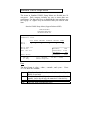
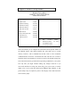
,*$'&)&)&#$&*$$$)%-&'/&%&
;'*$)$$&$&&'(&L
!!
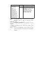
There are four selections for Power Management, three of which have
fixed mode settings.
$(
7>
&'
%$&
1. Disable
),
(&4
%&?4
+
0! :+ 4&
.&$&
A+ 8
")
0!
.+ & :+ )
%$& A+#%−
2
B+#%$")
2
+
!&−2
+
& :+ *
!$& A+
84.
?
*%$&
=7>&'>,
,, ->6>
''
Pre-defined timer values are used so that all
timers are in their MAX value.
7'4,,,-
',&4
System BIOS will ignore APM when power
management is running the system.
.,'>>7&6'6
,.7&'@
AB
7
7&,,A-,
,!A4-',
'A-7&>6'6
-6-,.,'
.6>,4'!
Note: − if APM is not installed, this option
has no effect.
System BIOS will never turn off the screen.
>-,.,',7
'
>-,.,',B
7
'
>-,.,',@
AB
7
'
-&$'!,
''?-,'
/)3/(3-.,
&.
The system BIOS will only blank off
-, >-,,-4
/03A>,
-9B;+B,,
'9= ,'
B+0!
-, ,.-
9= ,667&
=', -9$+
B,,,
$(
3+!3!
5 =
B
%$&
+
:+"
0&
)0 &
&
) &
-R/ (A ( &
% &
1 &
2 &
: &
< &
C &
0* &
00 &
0) &
0( &
0% &
01 &
BG
#%
+&
:+"
(&
-S/ (
:
*%$&
,$$ =#("$$(&(
#
You can choose the IRQ no. by yourself.
HDD’s motor will not be off.
$*&$#&#
$("&$$$
%&;'(&-(&$&&/+
$#$(&$&&
)$(5034(&+
4&$L
−-A/M-B/*"*$$$
(
$(+
−G%&;'
(&
)**$&$
$
#%+
)$(;$$T3
(&+
)0*
)*
(*
%*
0&
(&
1&
0*&
01&
)*&
(*&
%*&
0+
)+
(+
$*&$#&#$(
"&$)$($$T3
(&+
)$(-K/"
*$;$T3$("
&+
4&$L4&(),48(&
%#$
$)$($&&%&
!+,*()"&
%'&-3/+
"
+
$") 1. Disable
!&
2. 10 Sec
-S/ (: )*
(*
%*
0&
(&
1&
0*&
01&
20 Min
(*&
%*&
0+
)+
(+
+#%!& :+"
-S/ (:
""
System will never enter STANDBY
mode.
$*&$#&#
$("&$)$($
$,48(&+
If any item defined in (J) is
enabled and active, The
STANDBY timer will be reloaded.
4&$L4&(),48
(&
%#$$)$($&&
%&
!+,
*
()"&%'&
-3/+
System will never enter the
SUSPEND mode.
)0* )* (* %* 0 &
( &
1 &
0* &
01 &
)* &
(* &
%* &
0 +
) +
( +
$*&$#&#
$("&$)$($
$5034(&+
If any item defined in (J) is
enabled and active, The
SUSPEND timer will be reloaded.
4&$L4&()G$
5034(&%#$
$
)$($&&%&
!$*&*
$&%%
$*()"
&%'&-3/+
$(
D9=
/(E-3
"7 ;&
+/0E-3
&
5(/&)3
5%/&03
51/"7)3
5266.,!3
5:/"703
5</'3
5C/5)3
50*/,43
500/,43
50)/7$)',3
50(/6 ,,3
50%/+,!3
501/,43
%$&
*%$&
:+ ,%*;$*$;$)
&$*$$0!$(+
A+ 4 ,%*;$*$;$)
*#$0!,($&"
&+
&<(%$0&
!'($5$-0!5/
(&$&$%*
*$;$0!;$+
( :L $( ( $ -S/ $ (# " &
$
% ;# &' $ $( H0&
!'($H&$
*&'#$&H5H
,$(L$(H)$(&HH)$($")HMH)$(
#%H
R ( AL $&#' $ $( P 0& &H &$
*&$&")$
$(H0&!'($H$(&$(;#$
-/
&$%&&$'&"%&('($
"O
8&#*(#)*&'#$0.;*H =+,&&'
%'$)&#$&%$&&*$(*"$('&
*&%$&+
1( "3C31.!2 !(D$#5
$3" & !12 L $3" 0 !12 L $3" 9 !12 L $3" > !12 L "3 4!"#D ..#4
"3 7"##42#
"3 ..#4
1(D$#5
1(D$#5
1(D$#5
&" )(!$(D$# &'
0 )(!$(D$# &&
945 )(!$(D$# &0
>"- )(!$(D$# :
"!)#5 7 #)#$
015-(11#$ 1(D$#
(+3 C
4!%(47 L !" ↑↓→← #$#""#%
& #$+ BC35!.7
< $5($ # ,-!."/0 3$34
? 3(5#.( $"
A 3(5#" +#.( $"
,&&'%'$)&#$&%$&&*$(*"
$('&*&%$&+
$(
0, F
), F
(, F
%, F
%$&
*%$&
>
−,!-74 >- /3,>
,6
−- !>- -5,
4'-4
−-4 >- -5
-,,,
$(
+&$:5'
4,R
&$A5'
4,R
&$B5'
4,R
&$5'
4,R
+:$;"
=
A;"
=
B;"
=
$;"
=
.+0. =
*$;$
")
+0.3A
.
3+0.3 =
!%,&
%$&
5,
.
B
C
D
E
:F
::
:A
:
:C
4
3'
6;
3"
"
0.
5,
0.
6,:
0.
*%$&
.L,&%$&
;
&>$)@*
&(
*$)$(
*&$$*4,
&
$#+
4&$L
−.&&@5,@&
;*
#)&#&<*$)
*
*$);*
*
4,$$*#+
−.&&&)@5,@&
!#$
#*$&0.;*
"*#
&%$&.
&*$
$&' =&
#*$&
&)+
,)$('
$;" =$&$
�.;*+
,&$$*%$$ =
'%#$;&'
$''+
3""A*&
0.3*+$*#%&$
-:DFU:DD/ =:C
'($
0.5,
,L
−*&0.3;*
$($&*$&&$
6,A
0.
6,B
0.
6,
$(
3+0.3 =
!%
,&
+0()3
4,R
*&)3
4,R
%$&
0.
5,
0.
6,:
0.
6,A
0.
6,B
0.
6,
B
0.
3;*
-$("&/
*%$&
0.6,:
0.6,A
0.6,B
0.6,
−' =:&%()3
4,R =:C&*&)
34,R&$%*&$
−,&$'
)
=;0.3*
&#+*#&(3
**&*$$ =:M
:C
*$)&(&$
$&#'
*&+-,*&*
6'*)/
,&'$$#%$#("
$$#'")$0.3
*+
!"#
8&# * $ $ #%;& & # %& & "&$ & $(+
,*"$L
#%;&%&L*$*'$&%$&&$$#%
(#+
5%& LJ#$*&)$"#$&&$;$'$
$&*'
$&%$&&$$#%(#+
G )&# *$ $ #*$& $ &&' (' %%
$$*$&$*$&$)&#*$'%&+
34,3 0G L
,)% $ %& #% $& '$ **$ '$ %
13$2+ , %& $)% & * ) %;&#)
$ %& &( .! ((&)+ 8&# " $&
*&($%&+,)%$%&'%13$2+
8&# () & % 13*2 $& "&$ $ *$& &$ $ %&+
,&"%&J#$%13$2)&#%&(%$$&
$ %&+ (' *&( $ %& "
"+*$%&"$)$("&&$
)&#*$$#%)+
0G 63+
G%&"")&#"%&(%$$&$
$;)$()&#$)$&$$#%+,%;$##$&
%&&(*'')%$&)&#)$(*&'#$&+
$&)%&")&#*&I#$
$& I#$ %& ;) $( )&# )$( "&&$+
,&#%;$##$&#&)&#*&(%#$+
$$$%
$&
,3*3$#*#+,
&&'"*%$&&$$#+
:+$#%.'
12#$&$*$&
$#%%)%&"(&$$
#%%&$")$
*#'4 !66M6 3+
&&$#%%&$6(&&H6H&%$&
"&+
$#("&*)$&I#$&:FA&
P6 3H
&%$&"&+
5**$(&*%%&%$&$(+
= 4!)# #$#"4!)#+"!31,O6!+/
= = 0,/ &99 ?>; ?> ' 0<:> ?9 & &99: 0<:< &? ?<<9< 0<:>
?9 9 &99; &0:A 90
?9 ?<<9<
3"#3%##,CD#.34#<'/%
0<:>
" #M
N.34!1"($$("!31
12$.!$#%
= 4!)# #4,<&?/ &&0' &? ?<<9< &&&: <: 4!)# 31#,0'9/ ?;> &? ?<<9< ?;< 9; CCCCCCCCCC
G$)%P#H$)%$@!3@&%$&"
&%&#$&*$$&(&+
,#%%&$B(&L4 !66M
6 3
4 !6(&
,$'***(&*$$&
$3
*&$&()$&($&#'**'+
,(<(#(#("&*)M*$&&
4 !6(&
:FA:MB+
&+.)*
-:FA/
< &+ - :/
< &+*$&
- B/
< &+%*$& - C:A/
CA
!'")$
#$$&4 !6(&$(<(#(
**"
"CA
!'")$;$&#'$%)*()"
'$
$$$+
#$%#&"'$'(%"&
,**'($&$&&;*&($CA
!'")$"&$$*+,#("&*)M*$&
&$#%()&$"$#("%)*)*&$
$+
#'**'$3*&$&$&($
&'**"")*$&M*)#("
$&$&%)*$+
,(<(#(#%%&$")6(&
+
'")$*&"$")$&&'&(#L
&+.)*
- :FA/
< &+
- ACC/
< &+*$&
- B/
< ")$%*$&
- C:A/
+'")$
#%)*
,<$**(&#%%&$")$
&$+
&(3*&$(&$:FA*)$&#$$
6#%%&$-&(*#&&$$6/+,
%&;&$$$;$&#%%&$$&+
3<(%&6 3(&L
.86+
::AF
CF
3
:
BA
3.,
!3
CE
4 !6
CE
6 3
$*-&&$/$$$#("&*)
$
:FA");'$")A+$$($($#("&
(#$%")A+;$&($&%&*
"(4,:B&$&**$'$
+
!<(#(L
&+.)*-:FA/
< &+ - BA/
< &+*$& - B/
< ")$%*$&
- C:A/
: '")$
-B/ (
,& #%%&$ 6 & 6 3 (& & $ (#$ "
&(&$
;&;+ $ &$ &*$ $ ;* &#$ -4, :B/+ 8&# () &$ " " $&
**$6
-6 3/(&*$)&##'#%$'
)$(*%*$&4,:B+
$'((!#
-,>">"4'.,,,,4.'>-.
'.-,!-,.' .!,- ,,.'
-4., ,, -, !,,,-'. ->>,-&&.->">"4'.
+,!">4'.
"
9
#
"
7
&
B" +
, 4, 9
B"
* +
*
4!)# &0;0D
4!)#
'D
?0&
'
?>
'
'
?<<9<
=
0>;9
?<<9<
?9
'
6$> '
6
?$
6.-G>>A 0CC)C<-,,4
<'
5 $ 5% & & ) $& (&; &# $ *$&
%)&$#%%*+0V3$W$&**%$$*$&+
03*$&"&$$*$&&<$$5$$)+
!!& 2)!
*$&($;.&+6$$$"&$$&(
&$*$;#$&($*)$*$")$#$$)+
( &2(<&
#$&*"$*
,#$$)#$&($*)*"$*$$"
$*$
&$$'$&$*+
"$*
*$)$)%$&($&& $&"$* $
&$
$'$&$*+
!&)"$*
!&)$&($&&$"$*$&$
$'$
&$*+
$"$*
$ $ " $* $ & $ $ '$ &
$*+
."$*$"
.$&"$*$$&$$'$&
$*+
2!.2(&
$;
*$ $ $; #(" & $ ; &
* )&# $& %&( & ; &($+ 8&# ()
*$ &( : $& + .* $ &*#($$& $$ *(
$$;&$*&*$$;#("&*$F
&#$$)#$&($*$*$&+
#$&*"$*
, & $ #$$) $& * $ $ &($ ") *
$*+
$$
0182$&$$&;&($+
)
$ )&# ; ( $ *' $& .! ;# $
)$( *&$ "&&$ $ $ .! ;# *$ $#%
$$ $ )$( ") $#' $ $ 4 & 0' $
9 33,9 "#$$& & $ )$( *+ 8&# () & $$ ")
(#$&#) % 1.$2 1$2 1$2 )+ 5%&
$$$)$((($)%1$2$&&#$
.!;#&"&&$#%+
* &)
4,3L 0,*&$)%*)&#$%#$$&%&$
F+
7/-?3
*
0
(
1
*0*)
*(
*%
*1
*2
*:
*C
, 6
0
&,6 -A,->
)H-,4 ,>-4,
4 , ,
& /<)(:3
7''6/<)1C3
7''4'/<)1%3
-6
&; -
0,,.,' - !,'
),-,)12#&
(
?6- '6,,, ,'6.&
- '6,,,.,';6&,
6.-'&
****,->&
,-7>,
,4
H
,,/
.3
,4
0#.,
)
#. ,4
9,&, $ .
7',4, -6, -
&-6,
07'- ,.?7 -&.?,
)
&,6 -H/3
7/-?3
*
*
*
*
*
*
0*
00
0)0(
0%
01
02
0:
0C
00
0
0)C
(*
(0
, 6
0 H-,()64 ,>- ,6
6-,H'((0)*> ''./6,36+
),,7, .7.6
(
.7>&'H/
&,6 3
09.-',4
) .
(&, !
%77H, /77.3
,,77 , '6'
1,,;&'.74 ,/7.3
H-/%**−%*3
0 7','--6,4 6
/
.697'3
) &,7,6,6.; -,.,' !
6
( 9H & -'A=A
=$9=
,6.4 ,A-,6!>6
0H-7/&7 ,,.3
),4&/& -',6.4 3
(->',,, >"A6.-,A ;7
&,6 ,',,,
."/="B3
7A.6;,6
,,.,' - !,'/'6,,9,3
& -*,
& -0,
&6,,,
,4
,<)1%'*)
,<)1C6',!, -0
,<)1C6',!, -)
,4
,<)1C .
,4
9& - !,',A? H
/
.3
,4
,&'.;
?&'.H
0,,&'.')12#2%*#
),
?&'.'0&-6''.
7/-?3
()
(((
(
(
(
(%*
%0
%)
%(
%%
%1
%2%
%
%
1*
10
1)
1(
2*
, 6
0 ,6.->7;7.
?,',,
/77.3
) 7',6$ -6,/.3 &
6,A"76,A6 ,64
,4
>,,&6.
0H#.
),7)',
."4) -
' -6,'.-") -
-,,,.A- -,
720,4
0 7'-,--6,4 6
/"697'3
) ,A6''- -6,
>-64,-&
H66.,!4 H+4 ,77AH,;66,
,4
H'- 6 ,,
,4
-,. /, -,4A!3A,->
-',,,-, ;>,
6,,I0J!.
06,,>,A,!6,,>
)-
."/=.3
&4, .-, !
!-&
,4
0H&,
)"7H,/7.3
,,574 ,
H7&,
(77H,/77.3
,,A&'.A5;&774 ,
H77&,
%7',->,& 6,,
17'6. 6,
27>&'H
$,7&
7& H
0 ,77AH,;66,
) H'4.,-
'4' !4
69,7 / 7 3
. 6,
7/-?3
20
2)
2(
, 6
0."4) -
") --,.7(A-,
6>,!66
)-6,6 6,
( ", - -6,H
% ", - 7>&'H/=
.3
1->-,.,' 06.-,4 64
)7'-&" !A.6' ;.6' ,6
6,
0 -,. ---> A
6-
'/77.3
)''.--,,
(,.,'40C+
.,'-,',---,.
6,,- --6,.,'
?6 ,
7/-?3
, 6
*
6 ,6 '
0
'& ,
Chapter 5
Display
The on-board VGA interface of the NEAT-470 supports traditional analog
CRT monitors and a wide range of popular LCD, EL, gas plasma flat panel
displays. It can drive CRT displays with resolutions up to 1024x768 in 256
colors. It is also capable of driving color panel displays with resolutions of
640x480 in 256K colors.
5.1 Drivers and Utilities
5.1.1 Microsoft Windows 3.1
The graphic installation program,SETUP.EXE, supports a simple
installation procedure of the display driver program. You may install these
drivers either through Windows or in DOS. To use Setup, follow the steps
as below:
Ensure that MS Windows 3.1 is up and running properly, using the
standard VGA driver. Exit from Windows.
Place the Windows 3.1x display Driver Diskette in drive A. Type
A:<ENTER> to make it be the default drive. Type SETUP <ENTER>
to run the drive SETUP program. Press any key to get to the
application list. Using the arrow keys, select Windows Version 3.1
and press <ENTER> key. Press <ENTER> key to select All
Resolutions, then press <END> to begin the installation. At this point,
you will be asked for the path to your Windows system directory
(default C:\ WINDOWS). When the installation is complete, press
any key to continue. Press <ESC> key followed by Y to exit to DOS.
Change to the directory where you installed Windows (default
C:\WINDOWS )
Type SETUP<ENTER> to run the Windows Setup program. It will
show the current Windows configuration. Use the “up” arrow key to
move to the Display line and press <ENTER>. A list of display drivers
will be shown. Use the arrow keys to select one of the drivers starting
with an asterisk (*) and press <ENTER>.
Follow the directions on the screen to complete the setup. In most
cases, you may press <ENTER> to accept the suggested option.
When Setup is done, it will return to DOS. Type <WIN> to start
Windows with the new display driver.
5.1.2 MS Windows 95 / NT Mode Driver Install
ENSURE that the MS Windows 95 or NT is up and running properly
using the VGA driver that has been detected.
OPEN the “My computer” program group and SELECT the “Control
Panel” icon.
SELECT the “Display” icon and then SELECT the “Settings” page.
SELECT the “Change Display Type” selection bar, and then SELECT
the “Change” button next to the Adapter Type.
On the “Select Device” page, SELECT the “Have Disk” button to
install the display driver from the diskette.
After the “Have Disk” button selected a “Install From Disk” window will
appear. SELECT the “Browse” button to browse the directory
“X:\WIN95” of your diskette drive. (X=A or B)
The files *.INF will appear under the file name list. SELECT “OK” to
return to the “Install From Disk” window. Under the statement “Copy
manufacturer’s files from” SELECT “OK” to start installing the driver
files from the FLOPPY drive.
“Select device” window will appear. Under Models, the driver file
name will be listed, SELECT “OK” to close “Select Device”
window and select “Color Palette” and “Desktop Area” of your
choice.
Once the desired color palette (the number of colors) and desktop
area (resolution) has been chosen, the Windows 95 or NT system will
be restarted to load this accelerated driver.
5.1.3 MS Windows 95 Refresh Rate Utility Regulation
Open the “My computer” program group and SELECT the “Control
panel” icon.
Double click on DISPLAY and SELECT “CHIPS”. There will now be a
refresh tab for changing the refresh rate. You may click the tab to
change the refresh rate.
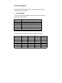
5.2 Panel Support
The NEAT-470 SBC board provides a very convenient way to setup
panels that are up to 16 types.
For 40K BIOS
If you install a standard 40K BIOS on the board, the NEAT-470 board
supports 8 panels as follows:
Panel #
1
2
3
4
5
6
7
8
Panel Type
1024x768 Dual Scan STN Color Panel
1280x1024 TFT Color Panel
640x480 Dual Scan Color Panel
800x600 Dual Scan Color Panel
640x480 Sharp TFT Color Panel
640x480 18-bit TFT Color Panel
1024x768 TFT Color Panel
800x600 TFT Color Panel
Meanwhile, please also set the jumpers on JP6 as the following:
Panel #
1
2
3
4
5
6
7
8
7-8
Open
Open
Open
Open
Open
Open
Open
Open
5-6
Close
Close
Close
Close
Open
Open
Open
Open
3-4
Close
Close
Open
Open
Close
Close
Open
Open
1-2
Close
Open
Close
Open
Close
Open
Close
Open
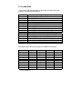
For 44K BIOS
If you install a standard 44K BIOS on the board, the NEAT-470 board
supports 14 panels as the following:
Panel #
1
2
3
4
5
6
7
8
9
10
11
12
13
14
15
16
Panel Type
1024x768 Dual Scan STN Color Panel
1280x1024 TFT Color Panel
640x480 Dual Scan Color Panel
800x600 Dual Scan Color Panel
640x480 Sharp TFT Color Panel
640x480 18-bit TFT Color Panel
1024x768 TFT Color Panel
800x600 TFT Color Panel
800x600 TFT Color Panel (44K BIOS only)
800x600 TFT Color Panel (44K BIOS only)
800x600 Dual Scan Color Panel (44K BIOS only)
800x600 Dual Scan Color Panel (44K BIOS only)
1024x768 TFT Color Panel (44K BIOS only)
1024x 768 TFT Color Panel (44K BIOS only)
Reserved
Reserved
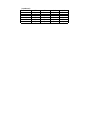
Meanwhile, please also set the jumpers on JP6 as the following:
Panel #
1
2
3
4
5
6
7
8
9
10
7-8
Close
Close
Close
Close
Close
Close
Close
Close
Open
Open
-$&"*&$#X/
5-6
Close
Close
Close
Close
Open
Open
Open
Open
Close
Close
3-4
Close
Close
Open
Open
Close
Close
Open
Open
Close
Close
1-2
Close
Open
Close
Open
Close
Open
Close
Open
Close
Open
( continued )
Panel #
11
12
13
14
15
16
7-8
Open
Open
Open
Open
Open
Open
5-6
Close
Close
Open
Open
Open
Open
3-4
Open
Open
Close
Close
Open
Open
1-2
Close
Open
Close
Open
Close
Open
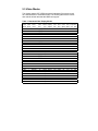
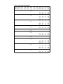
5.3 Video Modes
The display chipset C&T 65550 supports all standard VGA modes as well
as a wide selection of extended modes. The following table list the modes
and vertical refresh rates that this BIOS can support.
Table 1: Standard Video Display Modes
VESA
Video VBE
Mode Mode
00h
--
Pixel
Resolution
Color
Res.
320x200 16(gray)
320x350 16(gray)
360x400
16
01h
-320x200
16
320x350
16
360x400
16
02h
-640x200 16(gray)
640x350 16(gray)
720x400
16
03h
-640x200
16
640x350
16
720x400
16
04h
-320x200
4
05h
-320x200 4(gray)
320X200 4(gray)
320X200
4
06h
-640x200
2
07h
-720x350 Mono
720x350 Mono
720x400 Mono
08h-0Ch -Reserved
0Dh
-320x200
16
0Eh
-640x200
16
0Fh
-640x350 Mono
10h
-640x350
16
11h
-640x480
2
12h
-640x480
16
13h
-320x200
256
Mode Display
Type Adapter
Font
Size
Text
8x8
8x14
9x16
8x8
8x14
9x16
8x8
8x14
9x16
8x8
8x14
9x16
8x8
8x8
8x8
8x8
8x8
9x14
9x14
9x16
Text
Text
Text
Graph
Graph
Graph
Text
Graph
Graph
Graph
Graph
Graph
Graph
Graph
CGA
EGA
VGA
CGA
EGA
VGA
CGA
EGA
VGA
CGA
EGA
VGA
All
CGA
EGA
VGA
All
MDA
EGA
VGA
E/VGA
E/VGA
E/VGA
E/VGA
VGA
VGA
VGA
8x8
8x8
8x14
8x14
8x16
8x16
8x8
Dot Horiz. Vert Video
Char. Clock Freq. Freq Mem.
Disp. (MHz) (MHz) (Hz) (KB)
40x25
40x25
40x25
40x25
40x25
40x25
80x25
80x25
80x25
80x25
80x25
80x25
40x25
40x25
40x25
40x25
80x25
80x25
80x25
80x25
40x25
80x25
80x25
80x25
80x30
80x30
40x25
25
25
28
25
25
28
25
25
28
25
25
28
25
25
25
25
25
28
28
28
31.5
31.5
31.5
31.5
31.5
31.5
31.5
31.5
31.5
31.5
31.5
31.5
31.5
31.5
31.5
31.5
31.5
31.5
31.5
31.5
70
70
70
70
70
70
70
70
70
70
70
70
70
70
70
70
70
70
70
70
256
256
256
256
256
256
256
256
256
256
256
256
256
256
256
256
256
256
256
256
25
25
25
25
25
25
25
31.5
31.5
31.5
31.5
31.5
31.5
31.5
70
70
70
70
60
60
70
256
256
256
256
256
256
256
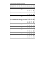
Table 2: Extended Video Modes
VESA
Video VBE
Mode Mode
20h
22h
24h
120
122
124
28h
128
2Ah*
--
30h
Pixel
Resolution
640x480
800x600
Color Mode
Res. Type
16
16
1024x768 16
Graph(L) Pack
Pix
Graph(L) Pack
Pix
1600x1200 16 Graph(L) Pack
Pix
101h 640x480 256 Graph(L) pack
Pix
100h 640x400 256
32h
103h 800x600 256
38h
Graph(L) Pack
Pix
1280x1024 16 Graph(L) Pack
Pix
31h
34h
Mem.
Org
Graph(L) Pack
Pix
Graph(L) Pack
Pix
105h 1024x768 256 Graph(L) Pack
Pix
107h 1280x1024 256 Graph(L) Pack
Pix
Font
Size
Dot Horiz. Vert
Char. Clock Freq. Freq
Disp. (MHz) (MHz) (Hz)
8x16 80x30 25.175
-4Interlaced
60
256
31.5
36
8x16 100x37 36
37.5
43.3
35.1
75
85
56
256
256
256
40
49.5
56.25
8x16 128x48 44.9
37.9
46.9
53.7
35.5
60
75
85
43,)
256
256
256
384
65
78.75
94.5
8x16 160x64 8.75
48.4
60
68.7
47
60
75
85
43,)
384
384
384
640
108
8x16 200x75 --
64
--
60
--
640
938
8x16 80x30 25.175 31.5
60
300
31.5 37.5
36
43.3
8x16 80x25 25.175 31.5
75
85
70
300
300
256
8x16 100x37 36
35.1
56
469
40
49.5
56.25
8x16 128x48 44.9
37.9
46.9
53.7
35.5
60
75
85
43,)
469
469
469
768
65
78.75
94.5
8x16 160x64 78.75
48.4
60
68.7
47
60
75
85
43(/
768
768
768
1280
64
60
1280
108
Notes:
31.5
Video
Mem.
(KB)
L = Linear * =Modes 3Ah is for flat panel only
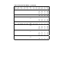
Table 2: Extended Video Modes (continued)
VESA
Video VBE
Mode Mode
3Ah*
40h
41h
42h
43h
--
Pixel
Resolution
Color Mode
Res. Type
Mem.
Org
1600x1200 256
Graph(L) Pack
Pix
110h 640x480 32K Graph(L) Pack
Pix
111h 640x480 64K Graph(L) Pack
Pix
113h 800x600 32K Graph(L) Pack
Pix
114h 800x600 64K Graph(L) Pack
Pix
44h
116h 1024x768 32K Graph(L) Pack
Pix
45h
117h 1024x768 64K Graph(L) Pack
Pix
50h
112h 640x480 16M Graph(L) Pack
Pix
52h
115h 800x600 16M Graph(L) Pack
Pix
6Ah
102h 800x600
Notes:
16
Graph
Planar
-4Interlaced L = Linear
Font
Size
Dot Horiz. Vert
Char. Clock Freq. Freq
Disp. (MHz) (MHz) (Hz)
8x16 200x75 -
--
1875
8x16 80x30 25.175 31.5
60
600
31.5 37.5
36
43.3
25.175 31.5
75
85
60
600
600
600
31.5 37.5
36
43.3
8x16 100x37
36 35.1
75
85
56
600
600
938
40
49.5
56.25
8x16 100x37 36
37.9
46.9
53.7
35.1
60
75
85
56
938
938
938
938
40
49.5
56.25
8x16 128x48 44.9
37.9
46.9
53.7
35.5
60
75
85
43(/
938
938
938
1536
65
8x16 128x48 44.9
48.4
35.5
60
43(/
1536
1536
65
48.4
8x16 80x30 25.175 31.5
60
60
1536
900
31.5
36
8x16 100x37 36
37.5
43.3
35.1
75
85
56
900
900
1407
40
8x16 100x37 36
40
49.5
56.25
37.9
35.1
37.8
46.9
53.7
60
56
60
75
85
1407
256
256
256
256
8x16 80x30
--
Video
Mem.
(KB)
* =Modes 3Ah is for flat panel only
Table 2: Extended Video Modes
VESA
Video VBE
Mode Mode
Pixel
Resolution
(continued)
Font
Size
8x16 128x48 44.9 35.5
65
48.4
78.75
60
94.5 68.7
8x16 160x64 78.75
47
108
64
8x16 80x30 25.175 31.5
43(/
60
75
85
43(/
60
60
384
384
384
384
640
640
300
31.5 37.5
36
43.3
8x16 80x25 25.175 31.5
75
85
70
300
300
256
8x16 100x37
104h 1024x768
16 Graph
Planar
68h
106h 1280x1024 16 Graph
Planar
70h
101h 640x480
Pack
Pix
256
Graph
71h
100h 640x400
256
Graph
72h
103h 800x600
256
Graph
78h
105h 1024x768 256 Graph
107h 1280x1024 256 Graph
Pack
Pix
Pack
Pix
Pack
Pix
Pack
Pix
36
35.1
56
469
40
49.5
56.25
8x16 128x48 44.9
37.9
46.9
53.7
35.5
60
75
85
43(/
469
469
469
768
65
78.75
94.5
8x16 160x64 78.75
48.4
60
68.7
47
60
75
85
43(/
768
768
768
1280
64
60
1280
108
Notes:
Video
Mem.
(KB)
Mem.
Org
64h
74h
Dot Horiz. Vert
Char. Clock Freq. Freq
Disp. (MHz) (MHz) (Hz)
Color Mode
Res. Type
-4Interlaced L = Linear
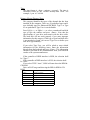
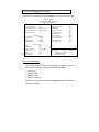
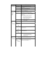
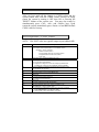
Appendix A
Watchdog Timer
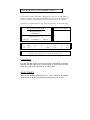
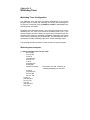
Watchdog Timer Configuration
The watchdog timer will reset the system automatically if the system
program does not refresh the watchdog timer during the watchdog time
out interval. It is defined at I/O port 0443H and 043H to enable/disable the
watchdog time out function.
Regarding to the watchdog function, user must have a program to set the
watchdog time out value, and refresh the watchdog timer cycle. If the
system program goes into a dead loop or goes into an abnormal cycle, the
watchdog timer cannot be refreshed immediately. Meanwhile, the system
will be reset by watchdog timer automatically. The watchdog timer will be
refreshed by “disable watchdog output” then “enable watchdog output”.
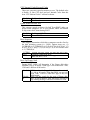
The following flowchart shows the normal structure of system program.
Watchdog timer examples:
(1) Setup watchdog timer time out value:
mov al,0ah
mov dx,70h
out dx,al
jmp short $+2
mov dx,71h
in al,dx
jmp short $+2
and al,0f0h
add ax,TimeValue
; TimeValue= 00h..0fh, reference as
following watchdog time out table
out dx,al
jmp short $+2
mov al, 0bh
mov dx, 70h
out dx, al
jmp short $+2
mov dx, 71h
in al, dx
jmp short $+2
or al, 08h
out dx, al
jmp short $+2
Watchdog Time Out Table:
Time Value
0
1
2
3
4
5
6
7
Time Out
None
0.5 sec.
1
sec.
0.015 sec.
0.03 sec.
0.06 sec.
0.125 sec.
0.25 sec.
56 Enable watchdog output:
mov dx, 443h
in al, dx
jmp short $+2
(3)
Time Value
8
9
A
B
C
D
E
F
Time Out
0.5 sec.
1 sec.
2 sec.
4 sec.
8 sec.
16 sec.
32 sec.
64 sec.
; SET WATCH DOG ENABLE
Disable watchdog output:
mov dx,043h
DISABLE
in al,dx
jmp short $+2
; SET WATCH DOG
Appendix B
Connectors’ Pin Assignment
Parallel/Printer connector (PRN)
Pin no.
Signal
1
Strobe
2
Data 0
3
Data 1
4
Data 2
5
Data 3
6
Data 4
7
Data 5
8
Data 6
9
Data 7
10
-Acknowledge
11
Busy
12
Paper Empty
13
+ Select
14
- Auto Feed
15
- Error
16
- INIT Printer
17
- Select Input
18-25
Ground
HDD Connector (IDE)
Pin no.
Signal
Pin no.
Signal
1
- RST
2
GND
3
D7
4
D8
5
D6
6
D9
7
D5
8
D10
9
D4
10
D11
11
D3
12
D12
13
D2
14
D13
15
D1
16
D14
17
D0
18
D15
19
GND
20
N.C.
21
N.C.
22
GND
23
IOW
24
GND
25
IOR
26
GND
27
IORDY
28
N.C.
29
N.C.
30
GND
31
IRQ
32
-IO CS16
33
A1
34
N.C.
35
A0
36
A2
37
CS0
38
CS1
39
-ACT
40
GND
FDD Connector (FDC)
Pin no.
1-33(odd)
2
4, 6
Signal
GND
High Density
Unused
8
Index
10
Motor Enable A
12
Driver Select B
14
Driver Select A
16
Motor Enable B
18
Direction
20
Step Pulse
22
Write Data
24
Write Enable
26
Track 0
28
Write Protect
30
Read Data
32
Select Head
34
Disk Change
CRT Display Connector (VGA)
Pin no.
Signal
1
RED
2
GREEN
3
BLUE
4
N/C
5
GND
6
GND
7
GND
8
GND
9
N/C
10
GND
11
N/C
12
N/C
13
H-SYNC
14
V-SYNC
15
N/C
Flat Panel Display Connector mini pin header (J3)
Pin no.
Signal
Pin no.
Signal
1
+12V
2
+12V
3
GND
4
GND
5
VDD
6
VDD
7
ENVEE
8
GND
9
P0
10
P1
11
P2
12
P3
13
P4
14
P5
15
P6
16
P7
17
P8
18
P9
19
P10
20
P11
21
P12
22
P13
23
P14
24
P15
25
P16
26
P17
27
P18
28
P19
29
P20
30
P21
31
P22
32
P23
33
GND
34
GND
35
CLOCK
36
FLM
37
M
38
LP
39
GND
40
EN_BKL
41
GND
42
ENVDD
43
VDD
44
VDD
RS-232 Connector (COM1)
Pin no.
Signal
1
DCD
2
RX
3
TX
4
DTR
5
GND
6
DSR
7
RTS
8
CTS
9
RI
10
N.C.
RS-232/422/485 Connector (COM2)
Pin no.
RS232
RS422
RS485
1
DCD
TX-
DATA-
2
DSR
RTS +
3
RX
TX+
4
RTS
RTS -
5
TX
RX+
6
CTS
CTS +
7
DTR
RX-
8
RI
CTS -
9
GND
GND
10
N.C.
N.C.
DATA+
PC/104 Connector
Pin no.
A
B
C
D
0
--
--
GND
GND
1
IOCHCHK*
GND
SBHE
MEMCS16*
2
SD7
RESETDRV
LA23
IOSC16*
3
SD6
+5V
LA22
IRQ10
4
SD5
IRQ9
LA21
IRQ11
5
SD4
-5V
LA20
IRQ12
6
SD3
DRQ2
LA19
IRQ15
7
SD2
-12V
LA18
IRQ14
8
SD1
OWS*
LA17*
DACK0*
9
SD0
+12V
MEMR*
DRQ0*
10
IOCHRDY*
GND
MEMW*
DACK5*
11
AEN
SMEMW*
SD8
DRQ5
12
SA19
SMEMR*
SD9
DACK6*
13
SA18
IOW*
SD10
DRQ6
14
SA17
IOR*
SD11
DACK7*
15
SA16
DACK3*
SD12
DRQ7
16
SA15
DRQ3
SD13
+5V
17
SA14
DACK1*
SD14
MASTER*
18
SA13
DRQ1
SD15
GND
19
SA12
REFRESH*
NC
GND
20
SA11
SYSCLK
21
SA10
IRQ7
22
SA9
IRQ6
23
SA8
IRQ5
-----
-----
PC/104 Connector
( continued )
Pin no.
A
B
C
24
SA7
IRQ4
25
SA6
IRQ3
26
SA5
DACK2*
27
SA4
TC
28
SA3
BALE
29
SA2
+5V
30
SA1
OSC
31
SA0
GND
--
--
32
GND
GND
--
--
Remark:
‘ *’ means ‘Low active single’
‘--' means ‘None’
--
D
-------
--------
Appendix C
41.Installing DiskOnChip
of M-systems
.
-,'4-,!-6,, -, , -., .'..
,->6 ,-,!-6
60-,!-6>--60, !
7,--,!-6-, ! .,.,
- ! '! , - ,!-6 , , , .A - 6,
% , - ,!-6 , 4 ,.,' >- - ,!A , -
&
,64""
/ -6-., ' ,!,
,3A- '6-,!-6)***>,,4
-,!-6,'>--,.,',
4
!"#$%
- !' )2$1 .!( & ' ! 1& & ' )2$1 2 & 2 % ' ,'&!7!8
/)2$1 .&&5 .6
- '& 2 . "( & '
."
"&(&&'& '&&'
)2$15)2$1 .16
1&&' )2$1
*.'& 2 &%&'
)2$1 & !! & ' .
! )2$1
!""$%
%)2$1!!' .5 '6('
. & 9 !' .( )2$1 .)' . ( .1'
. 9!' ' .()2$1
& . 1 % !' )2$1 ' .(
! '8
0
)
(
-,.,''!,-,!-6,, .,4
-6'6.6 !"#$
!%&&& '(
K-,.,'A-,!-6>66,4
Appendix D
Updating BIOS
You should find one diskette for updated BIOS program in the package.
The updating procedures are as the following:
1.
2.
3.
4.
5.
6.
Insert the diskette(There is a file “ AWDFLASH.EXE’) in drive A or B.
Type AWDFLASH under the prompt A or B.
The screen will ask you to enter the file name for programming.
Please enter the ‘filename’ for the updating BIOS that is from your
agent. Meanwhile, please type ‘N’ to answer the question ‘Do you
want to save BIOS (y/n)?’ at the bottom of the screen.
After that, please type ‘Y’ to answer the question ‘Are you sure to
program (y/n)?’ at the bottom line of the current screen.
Turn off the power after the system updates the BIOS.
Turn on the power again.
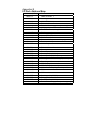
Appendix E
I/O Port Address Map
Address ( HEX )
000-01F
020-021
022-023
040-05F
043
060-06F
070-071
080-09F
0A0-0A1
0C0-0DF
0F0
0F1
0F8-0FF
1F0-1F8
200-207
278-27F
2E8-2EF
2F8-2FF
300-31F
378-37F
380-38F
3A0-3AF
3B0-3BF
3C0-3CF
3D0-3DF
3E8-3EF
3F0-3F7
3F8-3FF
443
Device
DMA controller 1
Interrupt controller 1
M1487/M1489 chipset address
Timer 1 & 2
Disable Watch-dog timer operation (read)
Keyboard controller
Real Time Clock, Non_Maskable interrupt
DMA page register
Interrupt controller 2
DMA controller 2
Clear math. Coprocessor busy signal
Reset math. Coprocessor
Math. Coprocessor
Fixed disk controller
Game port
Parallel port #2
Serial port #4 (COM 4)
Serial port #2 (COM 2)
Prototype card / Streaming Tape Adapter
Parallel port #1
SDLC, Bisynchronous 2
SDLC, Bisynchronous 1
Monochrome Display , Parallel port 0
EGA card
CGA card
Serial port #3 (COM3)
Floppy Disk controller
Serial port #1 (COM1)
Enable Watch-dog timer operation (read)
Appendix F
Memory Address Map
Address ( HEX )
0000000-009FFFF
00A0000-00BFFFF
00C0000-00EFFFF
00F0000-00FFFFF
0100000-BFFFFFF
Device
System memory
Display memory
I/O device BIOS ROM or RAM buffer
System BIOS ROM
System extension memory
Appendix G