1
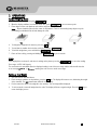
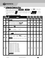
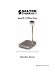
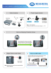
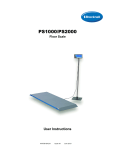
W W W. M E A S U R E T E K . N E T PS-103 User/Technical Manual Contents subject to change without notice Version 1.0 08/2013 TABLE OF CONTENTS 1. INTRODUCTION and INSTALLATION ..................................................................................................................... 1 General and Safety Information ............................................................................................................................................................... 1 Specifications............................................................................................................................................................................................ 1 Contents.................................................................................................................................................................................................... 2 Load Cell Wiring ........................................................................................................................................................................................ 2 Installation ................................................................................................................................................................................................ 2 2. OVERVIEW OF CONTROLS AND FUNCTIONS ......................................................................................................... 3 Indicator Display Character Definitions .................................................................................................................................................... 3 Indicator Display....................................................................................................................................................................................... 4 Function Keys ........................................................................................................................................................................................... 4 3. OPERATIONS ....................................................................................................................................................... 5 Normal Weighing Mode ............................................................................................................................................................................ 5 ZERO......................................................................................................................................................................................................... 5 Setting a Tare Weight................................................................................................................................................................................ 5 4. Calibration .......................................................................................................................................................... 6 5. View ADC Code or Power Voltage ........................................................................................................................ 7 6. Configuration Parameters Setup......................................................................................................................... 8 7. User Parameters Setup .................................................................................................................................... 12 8. Symbol Definitions: ........................................................................................................................................... 16 9. Trouble shooting: .............................................................................................................................................. 16 10. Replacement Parts ....................................................................................................................................... 18 11. One Year Limited Warranty ........................................................................................................................... 18 1. INTRODUCTION and INSTALLATION General and Safety Information Risk of Electrical Shock: Disconnect all power sources before making cable connections to the scale platform or indicator. For use in dry environments only. Do not operate in hazardous areas. Read and understand all operating instructions before using this product. Keep this manual for future reference. Record the weight shortly after placing a load on the platform. After extended periods, the load cell’s output signal may result in a less accurate reading. Place the scale on a hard, flat, and level surface before using. Avoid extended exposure to extreme heat or cold. Optimum operation is at normal room temperature. See operating temperature range in the specifications table. Allow the scale to acclimate to room temperature before using. Allow sufficient warm up time. Turn the scale on and allow up to 2 minutes for internal components to stabilize before weighing. Electronic scales are precision instruments. Do not operate near cell phones, radios, computers or other electronic devices that emit radio frequencies that may cause unstable readings. Avoid using in heavy vibration or heavy airflow conditions. Specifications Model Max Capacity Readability Display Resolution Construction Weighing Units Calibration unit Application Modes Display Zero Range Tare Range Stabilization Time Operating Temp. Humidity Range Power supply: Interface Feet Safe Max Overload Indicator Dimensions Base Dimensions PS‐103 12R975 PS-103-35 77lb (35kg) 0.05lb (0.02kg) 1:1540 12R976 12R977 12R978 12R979 PS-103-68 PS-103-75 PS-103-180 PS-103-200 150lb (68kg) 165lb (75kg) 397lb (180kg) 440lb (200kg) 0.5lb (0.2kg) 0.1lb (0.05kg) 0.5lb (0.2kg) 0.2lb (0.1kg) 1:300 1:1650 1:794 1:2200 Epoxy painted carbon steel, treaded surface lb / lb:oz / kg lb / kg Weighing 0.58” (15mm) 7-segment LCD, 51/2 digits +20% of full capacity Full capacity <3 seconds 40° to 105°F (5° to 40°C) <90% relative humidity, non-condensing Alkaline Batteries: 4 x “AAA” size cells AC Adapter: 6Vdc/500mA, with central positive USB USB Adjustable height 150% of capacity 5.73x2.08x0.71” (L x W x H) / 145.5x53x18mm (L x W x H) 12” x 12” x 2.28”(L x W x H) 12” x 12” x 2.52”(L x W x H) 305 x 305 x 58mm (L x W x H) 305 x 305 x 64mm (L x W x H) www.measuretek.net . 1 Contents Indicator AC120V/DC6V 500mA UL Adapter Owner’s Manual Scale Platform 6’ USB Cable Outer Hexagonal Wrench Load Cell Wiring PIN1 PIN2 PIN3 PIN4 --------------------- EXCITATION + SIGNAL + SIGNAL EXCITATION – 1234 Installation 1. Remove the scale from the packaging and place it on a work table with the feet facing up. Remove the shipping protection screw. See below pictures. 2. Place the scale on a hard, flat, and level surface. 3. Adjust the feet to level the scale. 4. Install the batteries or plug in the adapter. Now the scale is ready for use. PS‐103 www.measuretek.net . 2 2. OVERVIEW OF CONTROLS AND FUNCTIONS Indicator Display Character Definitions PS‐103 www.measuretek.net . 3 Indicator Display >0<- Scale is zeroed and gross weight is 0, tare is 0. Net - Display reading is net weight; tare is not 0. lb, kg, oz - Unit of measure. Hold - Scale is in dynamic weighing mode. - Hold flashes - actual fluctuating weight is displayed. - Hold does not flash - locked weight is displayed. Function Keys KEY PRINT/HOLD UNIT TARE ON/OFF/ZERO ON/OFF/ZERO +UNIT ON/OFF/ZERO +TARE PS‐103 MODE Weighing mode DEFINITION <3 seconds >3 seconds Setup or Calibration mode Weighing mode Send output data via the USB port Enter or exit HOLD mode Shift the flashing data entry position from right to left Select weight unit of measure Setup or Calibration mode Increase the digit in the flashing data entry position by 1 Weighing mode Setup or Calibration mode Tare the weight Confirm the input data and continue to next step Weighing mode <3 seconds >3 seconds Setup or Calibration mode Weighing mode (more than 3 seconds) Weighing mode (more than 3 seconds) Zero the platform weight Power off the scale Exit to normal weighing mode Enter user parameter setup mode Enter calibration mode www.measuretek.net . 4 3. OPERATIONS Normal Weighing Mode 1. Power on the scale by pressing the ZERO/ON/OFF key. 2. When the display stabilizes, but it doesn’t show zero, press ZERO/ON/OFF to set a new zero point. 3. Place objects on the scale platform and read the weight on the indicator. Note: Objects should be placed at the center of the platform. Corner or side loading heavy objects may risk overloading an individual load cell and damage the scale. 4. 5. 6. 7. Yes No To change the weight unit of measure, press the UNIT key. To send data to another device via the serial port, press the PRINT/HOLD key. To hold the weight data, press and hold the PRINT/HOLD key for 4 seconds. Power off the scale by pressing and holding the ZERO/ON/OFF key for 4 seconds. No ZERO If the display dose not shows 0, and there is nothing on the platter, press the ZERO/ON/OFF key to zero the reading. Zero range: ±20% * full Capacity. The zero function is unavailable when the displayed reading is out of the zero range and the indicator will show the error message 0﹉﹉﹉ or 0﹍﹍﹍, meaning the scale is over or under zero range. Setting a Tare Weight 1. Zero the scale as described above. 2. Place an empty container on the platform, press the TARE key. The display will return to zero, eliminating the weight of the container. The NET announciator will be lit on the display. 3. Put the material or object to be weighed in the container. The net weight will be displayed. 4. To exit tare mode, remove all weight from the scale. The display will show a negative weight. Press the TARE key to return the display to zero. PS‐103 www.measuretek.net . 5 4. Calibration Note: (1) Before calibrating the scale, you should prepare standard weights (more than 10% of FS weight) for calibration. (2) In the following steps, pressing ZERO/ON/OFF will exit calibration. 1. Move all weight from the scale. Under normal weighing mode, press and hold TARE and ZERO/ON/OFF keys for more than 4s to enter calibration mode. 2. The indicator will show “CAL-?”, which means the scale is ready for calibration. Press the TARE key to confirm and continue into calibration mode. 3. When “CAL.P0” is displayed, the scale will begin to calibrate the zero-point of the scale. Remove all weight from the scale. Press the TARE key to confirm, or press the ZERO/ON/OFF to exit this mode. After receiving the reasonable zero-point data, the next step will automatically occur. 4. When “CAL.P1” is displayed, the scale will be calibrated on second calibration point. xxxxxx kg (or lb) will be displayed. The default standard weight is 50%FS. Load 5%-100%FS weight on the scale, and use the HOLD or UNIT keys to input the loaded weight. Press the TARE key to confirm the input, and then the indicator will flash the input standard weight. After the scale becomes stable and receives the ADC’s data corresponding to the standard weights, and if the data is reasonable and acceptable, the indicator will automatically be directed to next step. If the second point cannot be calibrated correctly, it will display “CAL.Er” and return back to step3 for re-calibration. 5. When “CAL.P2”is displayed, the scale will be calibrated on third calibration point. xxxxxx kg (or lb) will be displayed. The default standard weight is 100% FS. Load 10%-100%FS (this must be equal or larger than the weight from the second calibration point) weight on the scale. Use the HOLD or UNIT keys to input the standard weight’s value. Press the TARE key to confirm. The indicator will flash the input weight. If the indicator receives reasonable data, it will go to next step automatically. If an error occurred, the scale will display “CAL.Er” and return back to step3 for re-calibration. 6. When “CAL.P0” is shown again, the scale will calibrate the zero-point again. Remove any weight from the scale, press the TARE key to confirm; the displayed data will flash. If the indicator receives reasonable data, it will calculate and store all parameters into EEPROM. Then it will auto-reset, and be directed to weighing mode. If an error occurred in calibration, the scale will display “CAL.Er” and then it necessary to repeart the procedure from step3. PS‐103 www.measuretek.net . 6 5. View ADC Code or Power Voltage 1. In normal weighing mode, press and hold HOLD/PRINT and ZERO/ON/OFF keys until “code” is shown, which means the indicator is working under display inner code mode. In this mode, you can examine the stability of the weighing system, the increment value of ADC code corresponding to the loaded weight, and/or power voltage to PCB. NOTE: 1) The increment of ADC code for FS weight must be larger or equal to 2 times of selected display division; otherwise, the calibration cannot be properly completed. E.g. the display division is 0.1kg. Load 100kg standard weight on the platform, the increment of A/D code is at least 2x 100kg/0.1kg= 2x1000=2000. In this case, the scale can be calibrated. Otherwise, smaller division need to be chosen. 2) The data should be stable; otherwise, the calibration cannot properly complete. 2. In this mode, you can calculate the proper ADC data at zero point by examining the A/D data for loaded weight. If the ADC increase for full capacity is NFS, the power-on zero range is set to Zp% FS and zero key range is set to Zk% FS. Then the proper ADC data of zero point is larger than (Zp%+ Zk%) x NFS. 3. ADC increase for full capacity (NFS) can be calculated by: Load the weight W on the platform, and the ADC increase for W weight is Nw. The ADC increase for full capacity WFS is (NFS)= (Nw)x (WFS)/W . 4. Press the UNIT key to select displaying weight inner code or input the inner working voltage value. When “U x.xx” is displayed, the display digit is voltage value, and the unit is V. The proper working power voltage is between 3.8V to 8V. 5. Press the TARE key to display filtered or un-filtered weight A/D data; when the HOLD announciator is lit, the data is filtered. 6. Press the ZERO/ON/OFF key to exit this mode and return to normal weighing mode. PS‐103 www.measuretek.net . 7 6. Configuration Parameters Setup 1. When the scale is off, press and hold ZERO/ON/OFF and PRINT/HOLD keys until ‘C0NF’ is shown, which indicates that the scale is in Configuration parameter setup mode. 2. During setup mode, press the UNIT key to change the flashed digits, and use the HOLD/PRINT key to shift the flashed position. Press the TARE key to confirm the flashed digits. Press the ZERO/ON/OFF key to exit this mode. 3. Summary of Configuration Parameters Setting: ParaDefault meter 12R975 12R976 12R977 12R978 12R979 setting setting setting setting setting Setting Display Resolution for main weight unit: 100–20000 C1 3000 1540 300 1650 794 2200 C2 Display Resolution for second weight unit (if main unit is kg 3307 or lb, then second unit is lb or kg): 100–25000 Note: it must be equal or less than 1.25×C1 1750 340 1500 900 2000 2 – 5; 2 2 0 2 1 2 - x0.01; 5 - x10; 2 1 1 1 1 C3 0 Division select: 0 – 1; C4 0 Decimal point: 1 - x0.1; 0 - x1; 3 - x0.001; 4 - x0.0001; C5 0 Main weight unit (Calibration and setting capacity weight units): 0 – kg; 1 – lb 1 1 1 1 1 6 Weight Units that can be chosen by UNIT key: 0-kg; 1-lb; 2-lb:oz; 3-kg/lb; 4-kg/lb:oz; 5-lb/lb:oz; 6-kg/lb/lb:oz (The limitation of units that can be used, refer to Table1 and Table2) 6 6 6 6 6 9 Power-on zero-point range: 0 - calibration zero -point ±1%FS; 1 - calibration zero –point ±2%FS; 2 - calibration zero –point ±3%FS; 3 - calibration zero –point ±4%FS; 4 - calibration zero –point ±5%FS; 5 - calibration zero –point ±10%FS; 6 - calibration zero –point ±20%FS; 7 - calibration zero –point ±50%FS; 8 - calibration zero –point ±100%FS; 9 - no limitation; 9 9 9 9 9 C6 C7 PS‐103 1 – 2; www.measuretek.net . 8 ParaDefault meter C8 2 C9 0 12R975 12R976 12R977 12R978 12R979 setting setting setting setting setting Setting Zero range for ZERO/ON/OFF button: 0 –power-on zero -point ±1%FS; 1 - power-on zero –point ±2%FS; 2 - power-on zero –point ±3%FS; 3 - power-on zero –point ±4%FS; 4 - power-on zero –point ±5%FS; 5 - power-on zero –point ±10%FS; 6 - power-on zero –point ±20%FS; 7 - power-on zero –point ±50%FS; 8 - power-on zero –point ±100%FS; 9 - no limitation; Select which zero point will be used after scale is powered on and current weight signal is within the power-on zero-point range: 0 - Current weight; 1 - Calibration zero point; 2 - Power-off zero-point (power-off tare weight as current tare weight). 6 6 6 6 6 0 0 0 0 0 0 Select which zero point will be used after scale is powered on and current weight signal is NOT within the power-on zero-point range: 0 - Prompt power on zero point is over range; 1 - Current weight; 2 - Calibration zero point; 3 - Power-off zero-point (power-off tare weight as current tare weight). 0 0 0 0 0 C11 6 Zero tracking range: 0=no tracking; 1=±0.25d; 2=±0.5d; 3=±1d; 4=±1.5d; 5=±2d; 6=±3d; 7=±4d; 8=±5d; 9=±6d. 6 6 6 6 6 C12 2 Digital filter intensity: 0= very weak; 1=weak; 2=middle; 3=strong; 2 2 2 2 2 5 Motion check range: 0=±0.25d, 1=±0.5d;2=±1d;3=±1.5d;4=±2d; 5=±3d;6=±4d;7=±5d;8=±6d;9=±7d; 4 2 4 2 4 C14 1 Max. weight display: 0=FS+0d; 1=FS+9d;2=101%FS; 4=105%FS; 5=110%FS; 6=120%FS; 8=200%FS; 9= No limitation 1 1 1 1 1 C15 0 0=BMI function is disabled 1=BMI function is enabled 0 0 0 0 0 C16 0 0= Do not recover parameters (Cxx & Uxx) to default set 1= Recover all parameters to default setting 0 0 0 0 0 C10 C13 PS‐103 3=102%FS; 7=150%FS; www.measuretek.net . 9 Table1: use Kg as calibration unit: Calibration division value 0.0001kg 0.001kg 0.01kg 0.1kg 1kg 10kg 0.0002kg 0.002kg 0.02kg 0.2kg 2kg 20kg 0.0005kg 0.005kg 0.05kg 0.5kg 5kg 50kg Table2: use LB as calibration unit: Calibration division value 0.0001lb 0.001 lb 0.01 lb 0.1 lb 1 lb 10 lb 0.0002 lb 0.002 lb 0.02 lb 0.2 lb 2 lb 20 lb 0.0005 lb 0.005 lb 0.05 lb 0.5 lb 5 lb 50 lb PS‐103 Display division value in different weight unit that can be used kg lb lb:oz 0.0001kg 0.0002lb Not available 0.001kg 0.002lb Not available 0.01kg 0.02lb 0.5oz 0.1kg 0.2lb 5 oz 1kg 2lb Not available 10kg 20 lb Not available 0.0002kg 0.0005 lb Not available 0.002kg 0.005 lb 0.1 oz 0.02kg 0.05 lb 1 oz 0.2kg 0.5 lb Not available 2kg 5 lb Not available 20kg 50 lb Not available 0.0005kg 0.001 lb Not available 0.005kg 0.01 lb 0.2 oz 0.05kg 0.1 lb 2oz 0.5kg 1 lb Not available 5kg 10 lb Not available 50kg Not available Not available Display division value in different weight unit that can be used Kg lb Lb:oz Not available 0.0001lb Not available 0.0005 kg 0.001 lb Not available 0.005 kg 0.01 lb 0.2 oz 0.05 kg 0.1 lb 2 oz 0.5 kg 1 lb Not available 5 kg 10 lb Not available 0.0001 kg 0.0002 lb Not available 0.001 kg 0.002 lb Not available 0.01 kg 0.02 lb 0.5 oz 0.1 kg 0.2 lb 5 oz 1 kg 2 lb Not available 10 kg 20 lb Not available 0.0002 kg 0.0005 lb Not available 0.002 kg 0.005 lb 0.1 oz 0.02 kg 0.05 lb 1 oz 0.2 kg 0.5 lb Not available 2 kg 5 lb Not available 20 kg 50 lb Not available www.measuretek.net . 10 4. More Information for Configuration Parameters: 4.1 The division (d) of scale is determined by C3,C4 and C5 : If C3=3 (interval is 5), C4=2(decimal point is x.xx), C5=1(unit is lb), Then C3xC4xC5=5x0.01xlb=0.05lb, So, d=0.05lb 4.2 The capacity is determined by C1 and d : If C1=3000, d=0.05lb, then C1xd=3000x0.05lb=150.00lb, So, the capacity (FS) is 150.00lb 4.3 Operation on C16 : If you need to recover all configuration and user parameters to their default value, modify the “0” to “1” when “C16 0” is shown, then press the TARE key to confirm. The indicator will display “dEF.?” and “?” is flashed, press the TARE key to confirm, then “dEF.?” will flash to indicate recovery processing; “C16 0” will be displayed when the processing is complete. When the indicator displays “dEF.?” and “?” is flashed, press the ZERO/ON/OFF key to exit this mode and not to recover parameters. NOTE: Different setting of the Configuration Parameters can result in the scale having a different performance! PS‐103 www.measuretek.net . 11 7. User Parameters Setup In normal weighing mode, press UNIT and ZERO/ON/OFF until “USer” is shown to enter in the user parameters setup mode. 2. During this mode, press the UNIT key to change the flashed digits, press the HOLD/PRINT key to shift the flashed position. Press the TARE key to confirm and save the set data and enter next setting. Press the ZERO/ON/OFF key to exit this mode. 3. Summary of User Parameters Setting: 12R975~12R979 Parameter Default Setting setting Auto-off time: 0: no auto-off function; U1 05 05 01-15: when no weight change or key operation is occurring, the scale will auto power off after 1-15 minutes. Backlight on-off mode option : 0= Backlight is always off; 1= Backlight is always on; U2 2 2 2= Backlight is auto on and auto off. The backlight will auto off after 10 seconds of stable weigh or no key operation, and it will auto on when the scale weight is unstable or key operation is occurring. HOLD/PRINT key function set: U3 2 2 0=HOLD, 1=PRINT; 2=HOLD and PRINT Hold function mode: 0=no hold function; 1=hold larger weight reading; U4 0 2 2-50=when weight is more than 10d and the variety is within ±2d~ ±50d, hold stable weight; When weight is below 10d and then over 10d and becomes stable, the new stable weight will be held. 1. U5 0 Serial communication output format: 0=communication is disabled 1=output stable weight, unit and status data after PRINT pressed, data has not been received; 2=output gross, tare, net weight, unit and status data after PRINT pressed; data has not been received; 3=continuously output displayed weight, unit and status data, data has not been received;4=continuously output gross, tare, net weight, unit and status data, data has not been received; 5=output weight, unit and status data one time when scale becomes stable; 6=output gross, tare, net weight, unit and status data one time when scale becomes stable; 7=Command –response mode. U6 3 Baud rate for Serial communication: 0=1200,1=2400,2=4800;3=9600;4=19200 3 U7 0 Serial communication data format: 0=8N1;1=7O1;2=7E1 0 PS‐103 www.measuretek.net 1 . 12 4. More Information for User Parameters Setting: U5 to set serial communication output format: (1). U5=0: No serial communication function. It will not transmit or receive any data even if the scale is installed with serial communication hardware. Serial communication function can be only activated when the scale is in normal weighing mode. (2). U5=1: Press PRINT key, the scale will output the current stable weight, weight unit, and current Status data ; it does not receive any data . The output format is as below: <LF>< weight reading, minus, decimal point, weight unit><CR><LF>H1H2H3 <CR><ETX> (3). U5=2: Press PRINT key, the scale will output the data of stable gross, tare, net weight, weight unit and current status data. The format is as follows: <LF><Gross: reading, minus, decimal point, unit><CR> <LF><Tare: reading, decimal point, unit><CR> <LF><Net: reading, minus, decimal point, unit><CR> <LF>H1H2H3<CR><ETX> The number of bytes used: Weight reading ----------------------- 8bytes; Minus ----------------------------------1byte; Decimal point -------------------------1byte; Weight unit ----------------------------2 or 5 bytes; Current status (H1.H2.H3) --------- 3bytes (4). U5=3: Continuously output of the current displayed reading, weight unit and current status data, it does not receive any data. The output format is same as U5=1. (5). U5=4: Continuously output of the current gross weight, tare weight, net weight data, weight unit and current status data, it does not receive any data. The output format is same as U5=2. (6). U5=5: When the scale is stable, it will output the current displayed reading ,weight unit, and current status data automatically one time, it does not receive any data. The output format is same as U5=1. (7). U5=6: When the scale is stable, it will output the current gross weight, tare weight, net weight unit and current status data automatically one time, it does not receive any data. The output format is same as U5=2. (8). U5=7: Bio-Serial Communication: after receiving an available command, the indicator will send out the corresponding messages. 5. More Details About Serial Communication The following details contain more information for when U5 is set to 7: a) b) The baud rate and data format is set by U6 and U7. Responses to serial commands will be immediate, or within one weight measure cycle of the scale. One second is adequate for use as a time-out value by remote (controlling) device. The length of the weight field will be 8 digit weight data, one for minus sign, one for decimal point, two for measure unit (e.g. “lb”, “kg”). If the unit is lb:oz, another two for “lb” and one for a space (<sp>) after lb. Units of measure abbreviations are always lower case. (1). If the weight is overcapacity, the scale will return ten ‘^’ characters (the field of minus sign, decimal point, weight data is filled by ‘^’). (2). If the weight is under capacity, it will return ten ‘_’ characters (the field of minus sign, decimal point, and PS‐103 www.measuretek.net . 13 c) d) weight data is filled by ‘_’). (3). If the zero point has an error, it will return ten ‘_’ characters. (4). The character will be ‘-’ for negative weight or a space character for positive weight. Minus sign follow after the first digit. (5). Useless leading zero before digits are suppressed. Key to symbols used <LF> : Line Feed character (hex 0AH) <CR> : Carriage Return character (hex 0DH) <ETX> : End of Text character (hex 03) <SP> : Space (hex 20H) H1H2H3 : Three status bytes <p> : Polarity character including minus sign for negative weight and a space character for positive weight W1-W8 : Weight data <dp> : Decimal point U1U2 : Measure units, “kg”, “lb”, or “lb oz” Commands and responses (1). Command: W<CR> (57h 0dh) Response: ① over capacity: <LF>^^^^^^^^^^u1u2<CR><LF>H1H2H3<CR><ETX> ② under capacity: <LF>_________u1u2<CR><LF> H1H2H3<CR><ETX> ③ zero-point error: <LF>----------u1u2<CR><LF> H1H2H3<CR><ETX> Note: If the weight unit is lb: oz, U1U2= “lb oz” in above item ①②③. ④ Normal weight is displayed, current weight unit is kg or lb, decimal point position is set by C4: <LF><p>w1w2w3w4w5w6<dp>w7w8u1u2<CR><LF>H1H2H3<CR><ETX> ⑤ Normal weight is displayed, current weight unit is lb:oz, <LF><p>w1w2w3w4w5w6lb<sp>w7w8<o><z><CR>H1H2H3<CR><ETX> Or <LF><p>w1w2w3w4w5lb<sp> w6w7<dp>w8oz<CR>H1H2H3<CR><ETX> (2). Command: S<CR> (53h 0dh) Response: <LF> H1H2H3<CR><ETX> (3). Command: Z<CR> (5ah 0dh) Response: <LF>H1H2H3<CR><ETX> Zero function is activated, and then it returns to current scale status, similar to pressing the ZERO key. If ZERO function cannot be activated, it will return to current scale status. (4). Command: T<CR> (54h 0dh) Response: <LF> H1H2H3<CR><ETX> TARE function is activated, and then returns scale status, similar to pressing the TARE key. If TARE function cannot be activated, it will return to current scale status. (5). Command: U<CR> (55h 0dh) Response: <LF>u1u2<CR><LF> H1H2H3<CR><ETX> Changes units of measure and return scale status with new units, similar to pressing the UNIT key. The new measure unit should be allowed to use as a C5 setting. If the weight unit is lb:oz, U1U2= “lb oz” PS‐103 www.measuretek.net . 14 (6). Command: L<CR> (4ch 0dh) Response: <LF> H1H2H3<CR><ETX> If HOLD function is enabled, go to or exit from HOLD mode, similar to pressing the HOLD key. (7). Command: X<CR> (58h 0dh) Response: NONE Power off the scale, similar to pressing and holding the ZERO/ON/OFF key for 4 seconds. (8). Command: all others Response: <LF>? <CR><ETX> Unrecognized command e) f) Additional Commands and Responses for Scale Base Application: (1). Command: F<CR> (46h 0dh) --- to restore factory calibration data Response: <LF>OK H1H2H3<CR><ETX> (2). Command: O<CR> (4Fh 0dh) --- zero point calibration Response: <LF>OK H1H2H3<CR><ETX> --- if zero calibration is sufficient <LF> H1H2H3<CR><ETX> ---- if zero calibration resulted in an error (3). Command: H<CR> (48h 0dh) --- weight calibration Response: <LF>OK H1H2H3<CR><ETX> --- if weight calibration is sufficient <LF> H1H2H3<CR><ETX> --- if weight calibration resulted in an error Output status bit meaning: The status bit definition: Bit 0 1 2 3 4 5 6 7 PS‐103 Byte 1 (H1) Byte 2 (H2) Byte 3 (H3) 0=stable 0= not under capacity 01=normal work mode 1= not stable 1= under capacity 10= hold work mode 0= not at zero point 0= not over capacity 00=not define 1= at zero point 1= over capacity 11= not define 0=not AD over 0=not Zero Over 0= gross weight 1=AD over 1=Zero Over 1= net weight 0=not Zero down 0=not AD down 0= eeprom OK 1= Zero down 1=AD down 1= eeprom error always 1 always 1 always 1 always 1 always 1 always 1 always 0 always 1 always 0 parity Parity parity www.measuretek.net . 15 8. Symbol Definitions: 0﹉﹉﹉ -Zero point is over the setting range 0﹍﹍﹍ -Zero is below the setting range Ad﹉﹉﹉ -Analog digital converter chip over max. range Ad﹍﹍﹍ -Analog digital converter chip below min. range ﹉﹉﹉﹉ -Weight signal is too large ﹍﹍﹍﹍ -Weight signal is too small EEP.E1 -Config parameters incorrect (no set, no calibration, over normal range, etc.) EEP.E2 -User parameters are incorrect CAL-Px -Calibration point CAL.Er -Error in calibration CAP.-- -The setting full capacity will be displayed Cx.y -No. x configuration parameter is set to y Ux.y -No. x user parameter is set to y Lo.bAt -Battery voltage is below 3.6V 9. Trouble shooting: SYMPTOM Does not turn on. Ad﹉﹉﹉ Ad﹍﹍﹍ 0﹉﹉﹉ 0﹍﹍﹍ ﹉﹉﹉﹉ ﹍﹍﹍﹍ PS‐103 PROBABLE CAUSE 1. AC adapter is not securely connected 2. Low battery 3. Indicator is damaged REMEDY 1. Re-plug the AC adapter or rotate the plug to securely connect to the scale 2. Replace the batteries 3. Replace with a new indicator and preform calibration 1. The cable from platform to indicator is not 1. Check the cable or replace with a new correctly connected, or disconnected, or cable short circuit 2. Replace with a new indicator and perform 2. Indicator is damaged calibration. 3. Load cell cable is broken 3. Return the scale for repair 4. Load cell is damaged Reduce the weight on platform, till the Indication is out of key zero range indication is within the key zero range. 1. Loosen the shipping protection screws 2. Check whether an object is stuck between Weight reading below Power On Zero limit. scale base, if yes, remove the object. 3. Perform zero calibration. 1. Weight reading exceeds Overload limit 1. Reduce load on the scale until a weight 2. The weight value cannot be displayed in value is displayed. the current unit of measure because it 2. Use a more appropriate unit of measure. exceeds 6 digits. 1. loose the shipping protection screws Weight reading below Under load limit 2. Perform zero calibration www.measuretek.net . 16 SYMPTOM EEP.E1 EEP.E2 CAL.Er Cannot zero the display 1. Max. CAPACITY not same as marked on overlay 2. Any function invalid 3. Any measuring units missed Weighing is not accurate PS‐103 PROBABLE CAUSE REMEDY Re-set CONFIG parameters as technical manual CONFIG parameters are not correctly set instructed. Re-set USER parameters per the Technical USER parameters are not correctly set manual 1. Input data or loaded weight is too small, 1. Input correct data, load correct weight too big onto platform. 2. Weight signal is unstable, un-linear 2. Return the scale for repair 1. Load on scale exceeds allowable limits. 1. Remove load from the scale. 2. Wait for the load to stabilize. then press the (20%FS) ZERO/ON/OFF key to zero the display 2. Load on the scale is unstable CONFIG and USER parameters are not correctly Re-set CONFIG and USER parameters per the set Technical manual 1. An object is stuck between the load cell and scale base 2. Load cell received a heavy impact 3. The scale is at a location far from Chicago www.measuretek.net 1. 2. 3. 4. Remove the object Perform Linearity calibration Loose the shipping protection screws. Place the load on the center of the weighing platform . 17 10.Replacement Parts Part Number MH12R97602G Description AC120V/DC6V 500mA UL adaptor 11.One Year Limited Warranty MeasureTek products covered in this manual are guaranteed to be free from defects in material and workmanship for a period of one year after date of purchase. Misuse, accidental damage, overload, alteration, and improper installation are expressly excluded. Any product which is determined to be defective in material or workmanship within this time period may, as the exclusive remedy, be returned to an authorized MeasureTek distributor or service center, freight prepaid with prior return authorization, to be repaired or replaced at the manufacturer’s option. MeasureTek’s liability under this warranty is limited to the repair or replacement of the defective product and in no event shall MeasureTek be liable for consequential or indirect damages. PS‐103 www.measuretek.net . 18