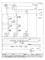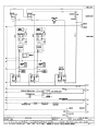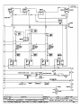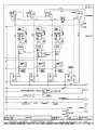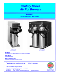
1
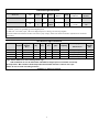
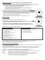
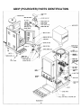
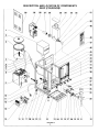
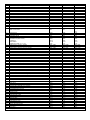
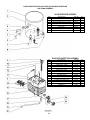
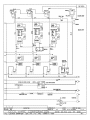
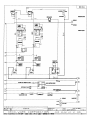
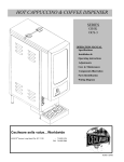
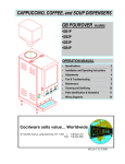
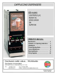
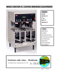
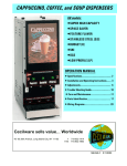
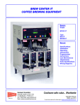
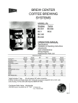
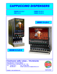
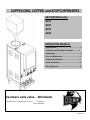
CAPPUCCINO, COFFEE, and SOUP DISPENSERS
GB POUROVER models:
•GB1P
•GB2P
•GB3P
•GB4P
OPERATION MANUAL
• Specifications...................................................…. 2
• Installation and Operating Instructions.............. 4
• Adjustments..........................................…............. 6
• Care and Maintenance.........................….............. 8
• Components Illustration.....…............................. 11
• Parts Identification...................…........................ 15
• Wiring Diagrams..........................…..................... 21
Cecilware sells value... Worldwide
45-05 20th Avenue, Long Island City, NY 11105
• 718-932-1414
FAX 718-932-7860
NH79A 11/99
Electrical Specifications
Model No.
Volts
Phase
Hz
Watts
GB1P, GB2P, GB3P
120V
1
60
1.8KW
Number of
Heaters
1
GB1P, GB2P, GB3P, GB4P
120/240V
240
1
1
50/60
50/60
3.0KW
3.0KW
1
1
15
Receptacle
Nema No.
5-15R
Circuit
Breaker
15A
15
15
L14-20R**
L6-20R
20A
20A
Amps
120V, 1.8 KW, 15A, Nema 5-15R standard on ail models; 3.0 KW, 120/240V units available
** 120/240V, 3 pole, 4 wire grounding type Twist-Plug Receptacle.
For 240V units. Use L6-20R, 2 pole, 3 Wire Twist-Plug Receptacle. For Wiring, refer to Wiring Diagrams.
See Electrical Data Label attached to the back of the unit for proper voltages, breaker sizes and electrical outlet requirements for each model
number listed.
Mechanical Specifications
Model#
No. of
Hoppers
Hopper
Capacity
(lb.)
Width
(in.)
Dept.
(in.)
Height
(in.)
Tank
(gal.)
Burst
Capacity
Lit Display Area
(7X13)91
70
(W x H) sq. in
Ship
Weight
(Ib.)
GB1P-LD
1
4 Ib.
8.5
22
31.5
1.5
15
GB2P-LD
2
4 Ib.
8.5
22
31.5
1.5
15
(7X13)91
75
GB3P-LD
3
4 Ib.
11
22
31.5
2
22
(9.5X13) 123.5
90
GB4P-LD
4
4 Ib.
14.125
22
31.5
4.5
45
(12.375X13) 123.5
100
Height: Add an additional 4" when installing with 4" legs.
Add an additional 14" min for water bottle and additional height space to invert bottle over the top.
*Burst Capacities - Max. number of drinks dispensable with available hot water - based on 6 oz. cups.
** Add 2" for line cord and valve fitting clearance.
Plumbing: ¼” water line required.
2
START UP INSTRUCTIONS FOR GB POUROVER
CAPPUCCINO DISPENSER
(see illustration 9-3 for clarification)
I.
INSTALLATION INSTRUCTIONS
This equipment is to be installed to comply with the applicable Federal, State, or local plumbing codes having jurisdiction.
In addition:
1. A quick disconnect water connection or enough extra coiled tubing (at least 2x the depth of the unit) so that the machine can be moved for
cleaning underneath.
2. An approved back flow prevention device, such as a double check valve to be installed between the machine and the water supply.
The GB beverage dispenser is equipped with a '/4" Flare Water Inlet Fitting which is located on the left side in the back of the base (when looking
at the machine from the front).
HIGHLY RECOMMENDED: A WATER SHUT-OFF VALVE and A WATER FILTER, preferably a combination Charcoal/ Phosphate Filter,
to remove odors and inhibit lime and scale build up in the machine.
Note: In areas with extremely hard water, a water softener must be installed in order to prevent a malfunctioning of the equipment and in order
not to void the warranty.
After the machine has been unpacked and placed on a counter, pull out the stainless steel drip tray. It should contain
the following: A Set of 4 Adjustable Leveling Legs & Water Inlet Fitting.
Connect the ¼” dia. copper waterline to the ¼” flare water inlet fitting of the valve.
Caution: Do not plug into power outlet yet.
Make sure the Heater Switch is OFF (Toggle Down) (see below door).
II.
PRIMING- MANUAL/BOTTLE POUROVER - Water Selection Switch -Toggle Up (See Back Panel)
1. Do NOT plug into power outlet yet.
2. Make sure Heater Switch is in the OFF position.
3. Fill reservoir tank (top) with 2 gallons of water, wait about 3 minutes for water to fill Heating Tank below. Refill Top Reservoir Tank with
another 2 gallons of water.
The unit will NOT dispense unless the Top Reservoir Tank is at least 1/2 full. So keep Reservoir Tank full.
Note: The unit has a Float-low water cutout switch (item 2, 111. h-1) inside the Reservoir Tank, which stops the machine from
dispensing when the Reservoir Tank is empty.
4. Plug into power outlet.
5. Turn Heater Switch ON.
6. Allow 10 to 15 minutes for water to reach dispense temperature of 185°F. Heater Indicator Light (red) goes ON when heater is on (see
lower front panel).
7. Fill hopper with product.
8. Place cup under dispenser.
9. Push and hold Dispense Button (green) until water flows from mixing chamber.
10. Machine is primed and ready to go.
3
III. PRIMING - AUTOFILL - Water Selection Switch - Toggle Down (See Back Panel)
1. Plug into power outlet.
2. Turn Heater Switch ON.
3. Allow 10 to 15 minutes for water to reach dispense temperature of 185°F. Heater Indicator Light (red) goes ON when heater is on (see
lower front panel).
4. Fill hopper with product.
5. Place cup under dispenser.
6. Push and hold Dispense Button (green) until water flow s from mixing chamber
7. Machine is primed and ready to go.
IV. POUROVER-PORTABLE BOTTLE OPERATION (Water Selection Switch - toggle UP) UNIT CAN BE OPERATED WITH A
3 GALLONS CAPACITY FRESH WATER BOTTLE. TO OPERATE WITH PORTABLE BOTTLE, proceed AS FOLLOWS:
1. Remove Reservoir Tank Cover.
2. Make sure that Reservoir Tank is only 1/2 full or empty, to prevent water spillage. To remove excess water push dispense
button.
3. Fill bottle with water.
4. Invert bottle into reservoir tank in one motion to minimize spillage.
5. Remove and refill bottle when "REFILL" light is ON.
NOTE: REFILL LIGHT, ON THE FRONT DOOR PANEL, WILL GO ON, WHICH INDICATES THAT THE WATER TANK MUST
BE REFILLED. WHEN REFILL LIGHT GOES ON, THE UNIT WILL NOT DISPENSE UNTIL TANK IS FILLED WITH WATER.
REFILLING WITH HOT TAP WATER WILL SHORTEN HEAT UP TIME.
V. NORMAL OPERATION (POUROVER AND AUTOREFILL)
1. Place a 6 oz. or larger cup under the left dispense nozzle, then press and hold the left dispense switch for 6 seconds. The machine
will dispense water at the rate of 1 oz. per second. Repeat it several times to check for consistent output.
2. While the tank is heating up, remove the hopper, load with product and reposition it back in the machine. When Ready Light goes
ON. the tank has reached its brew temperature and the machine is ready to begin dispensing the first cup of Cappuccino.
VI. WATER FLOW ADJUSTMENTS
THE UNIT IS FACTORY ADJUSTED TO DISPENSE WATER AT THE RATE OF 4 oz/sec. TO INCREASE
OR DECREASE FLOW, PROCEED AS FOLLOWS:
1. Remove Left side panel and locate Dispense Valve mounted on tank, with Flow Adjuster facing up, underneath cold water reservoir.
2. Locate Flow Adjustment Screw (white) on Dispense Valve. Use Allan Key to reach Flow Adjuster.
3. Rotate Adjustment Screw Counterclockwise to INCREASE flow rate.
4. Rotate Clockwise to DECREASE flow rate.
When making adjustments, do not adjust by more than 1/4 turn at a time, without checking output flow or drink strength
(ratio of water to powder).
4
DRINK STRENGTH ADJUSTMENT - Adjusting the AUGER SPEED or the WATER FLOW RATE ON DISPENSE VALVE.
I. UNITS WITH FIXED SPEED AUGER MOTORS-AC [CD150] • Fixed Auger Speed [95 RPM] and dispenses powder at a constant fixed rate.
Drink Strength adjustments can be made by adjusting the water flow rate on the Water Dispense Valves. [See ILL. C]
1. Remove Hoppers to access the Dispense Valve, located behind the hoppers.
2. Locate Flow Adjustment Screw on Dispense Valve. (See illustration C)
3. Rotate adjustment screw Counterclockwise to INCREASE Flow Rate, Clockwise to DECREASE Flow Rate.
(Note: the water flow rate should not exceed 1 to 1.3 oz./sec.)
Do not turn Adjustment Key more than 1/4 turn at a time without checking drink strength (ratio of water to powder).
II. UNITS WITH VARIABLE SPEED AUGER MOTORS-DO [CD151] • Variable Auger Speed [10 to 130 RPM]
Drink or Product Strength adjustments can be made by adjusting the Auger Motor RPM [knob on inside door panel], which
controls the amount of product being dispensed [gram throw]. The gram throw is factory preset at 7. Because the
consistency of each product varies, the customer can set the desired gram throw for each hopper.
The water flow rate on the Dispense Valves should remain fixed.
Note: the water flow rate should not exceed 1-1.3 oz./sec to avoid spillage from dispense chamber. [See ILL. C]
DRINK SIZE ADJUSTMENT
a. MANUAL MACHINES: Hold down the Dispense Button until desired amount is dispensed.
b. AUTOMATIC MACHINES WITH TIMER L493A ON INSIDE DOOR PANEL NOT PROGRAMMABLE] & SPEED CONTROL BOARD L556A
To increase the volume, turn the dial to the next increment. [0-1 is equivalent to 2 sec.]
c. AUTOMATIC MACHINES WITH PROGRAMMABLE "TEACH ME”-TIMERS [L576A OR L582A]:
These units do not have a cup size adjustment knob inside the door, since the timer is programmable from the dispense button.
PROGRAMMING INSTRUCTIONS FOR "TEACH ME" TIMERS; DISPENSE BUTTONS
PROGRAMMING FOR AUTOMATIC DISPENSE
PROGRAMMING FOR MANUAL DISPENSE
1. Press and Hold STOP [red] Button with one hand.
1. PRESS AND HOLD STOP [red] BUTTON WITH ONE HAND.
2. Press and Hold DISPENSE [green] Button with other land.
2. PRESS AND HOLD DISPENSE [green] BUTTON WITH OTHER HAND.
3. Release STOP [red] Button only.
4. Release DISPENSE [green] Button.
3. RELEASE STOP [red] BUTTON.
4. RELEASE DISPENSE [green] BUTTON.
5. Press and Release DISPENSE [green] Button to start time.
Product begins dispensing.
6. When it reaches the desired level in the cup,
Press and Release DISPENSE [green] Button to stop time.
Product stops dispensing.
5. PRESS AND RELEASE STOP [red] BOTTON.
7. DISPENSE Button can be jogged to top off cup.
8. Press and Release STOP [red] button, to lock in total dispense time.
9. Repeat steps 1 to 8 for each Dispense Button.
The Total Time The Water Is Running Is Accumulated And Saved Into Memory. For Normal Operation, Press and Release Dispense Button.
The Timers Have Been Factory Preset for 6 oz. Cups for Coffee; For 8 oz. Cups for Soup and Cappuccino.
To Change To Larger Or Smaller Cup Sizes [Volumes] Repeat Steps 1 To 8 Above.
TO CHECK VOLUME AND GRAM THROW DISPENSED (RATIO):
1. Remove the product guide from the hopper and position a receptacle under the hopper nozzle to catch the gram throw of product. Also place a measuring cup under
extension tube to catch the water dispensed.
2. Push the dispense button and check the amount of product dispensed, amount of water dispensed, and time [use stop watch] to dispense that water.
3. The amount of water dispensed in the measuring cup divided by the amount of time to dispense that water is the Water Flow Rate from Dispense Valve.
FOR CAPPUCCINO: The machine is factory adjusted to dispense 4-4.5 gr./sec. per OZ. Cup. [32 grams Product per 8 oz. cup]
The recommended throw is 28-32 grams per 8 oz. cup for Cappuccino, with 80% fill.
FOR COFFEE:
The machine is factory adjusted to dispense 0.3 gr./sec per OZ. Cup. [1.5 grams of coffee product per 5 oz. of liquid (in a 6 oz. cup).
The recommended throw is 1.5 to 1.8 grams per 6 oz. cup of Coffee, with 80% fill.
FOR SOUP:
The machine is factory preset to specified customer requirements, because the gram throw for each soup flavor and type varies
considerably with the consistency of each product. Adjustments can be made by the customer, as shown above.
For customer specified/special settings see inserts I, II, III, etc.
5
GB3P (POUROVER) PARTS IDENTIFICATION
DESCRIPTION AND LOCATION OF COMPONENTS
GB3P (POUROVER)
ITEM
1
2
3
4
5
6
7
8
9
10
11
12
13
14
15
16
DESCRIPTION
WATER BOTTLE 3 gal / OR 6 gal
RESERVOIR ICOVER
RESERVOIR ASSY
SILICONE HOSE - RESERVOIR TO TANK
SILICONE HOSE - BREATHER TUBE TO BREATHER TUBE
SILICONE HOSE - HOSE BARB TO RESERVOIR
HOSE BARB,REOUCER
SILICONE HOSE - WATER INLET VALVE TO HOSE BARB
TANK WELDMENT ASS'Y, (for 1 Heater) (HOT WATER)
SWITCH, WATER SELECTION – POUROVER/AUTOFILL
POWER/ ELECTRICAL CORO
WATER LEVEL SENSOR (CCA)
TERMINAL BLOCK 120V f OR 240V
BRACKET, TERMINAL BRACKET
BALLAST
RELAY, (NORMALLY OPEN) OR I RELAY, (NORMALLY OPEN, NORMALLY CLOSED)
TIMER 120V-OPTIONAL
17
18
19
20
LEGS (SET OF 4)
HOSE NUT ASS'Y
WATER INLET VALVE
BLOWER ORYER
MOUNTING CLIP (VENT. MOTOR)
BLOWER CUP
ELBOW INSERT
BLOWER DUCT HOSE 16" x (1 “ DIA)
21
POWER SWITCH (120V) OR f (120/240V)
22
RINSE SWITCH
23
HEATER SWITCH, 30ASPST (120V) OR; |120/240V)
24
HEATER INDICATOR LIGHT (amber)
25
DRIP TRAY PAN metal
26
DRIP TRAY GRILL
27
DOOR HARNESS ASSY
28
WHIPPER MOTOR short shaft
29
SLINGER DISC
30
CHAMBER MOUNTING GROMMET
31
CHAMBER MOUNT
32
"0" RING #125 (used w/ grommet)
33
WHIP BLADE
34
EXTENSION TUBE
35
WHIP CHAMBER
36
MIXING CHAMBER
37
DISPENSE CUP
38
"0" RING WHO) (used w / socket CD67A)
39
MIXING BOWL SOCKET
40
READY DISPENSER INDICATOR LIGHT (green)
41
POWER INOICATOR LIGHT (red)
42
OISPENSE BUTTON / SWITCH
43
STARTER BASE (for lamp inside door)
44
STARTER, TYPE FS - 5, 5-6-8 WATT
45
BULB, TYPE F8T5/CW
46
DDOR LATCH
47
LAMP HOLOER
48
DOOR WELDMENT ASSEMBLY, less components
49
TOP COVER! LID HINGE
50
MAINTANANCE INSTRUCTIONS
51
TOP COVER/LID, FRONT
52
PRODUCT GUIDE
53
NYLON AUGER
54
AUGER BUSHING, FRONT
55
HOPPER ASS'Y
56
AGITATOR GEAR
57
HOPPER COVER
58
AUGER BUSHING, BACK
59
NUT (FLANGE)
60
SCREW, FOR AUGER MOTOR
61
AUGER MOTOR (90 RPM)
62
SIDE PANELS
* Recommended spare parts
8
GB1P
M518A /M519A
97128
01740
M540A
M541A
M542A
K534A
M543A
?
L069A
C035A
L398A
B117A/B116A
RE18A
CE221
B129A (1)/B138A (1)
58017
GB2P
M518A /M519A
97128
Q174Q
M540A
M541A
M542A
K534A
M543A
?
L069A
C035A
L398A
B117A/B116A
RE18A
CE221
B129A(2)/B138A (1)
58017
M172A
K178A
L462A
CD56A
RA67A
CD57A
CD 108
C0107
L069A I L299A
L446A
L069A I L299A
C002A
R111A
R123A
CF19A
CD75A
CD 126
CD66A
CD65A
M379A
CD64A
M467A
CD63A
CD62A
CD61A
M378A
CD67A
C072A
C165A
L455A
B128A
L396A
CE76A
M367A
CE220
RD030
P402A
N978A
RC96A
C070A
C0130
C0102
CD68A
CD117
CD106
CD138
CD136
P443A
CD 150
RH91A
M172A
K178A
L462A
CD56A
RA67A
CD57A
CD108
C0107
L069A I L299A
L446A
L069A /1299A
C002A
R111A
R118A
CF19A
C075A
C0126
CD66A
CD65A
M379A
CD64A
M467A
CD63A
CD62A
CD61A
M378A
CD67A
C072A
C165A
L455A
B128A
L396A
CE76A
M367A
CE220
RD03Q
P402A
N978A
RC96A
CD70A
CD130
CD102
CD68A
CD117
CD106
C0138
CD136
P443A
CD 150
RH91A
GB3P
M518A/M519A
97128
01740
M540A
M541A
M542A
K534A
M543A
RL40H
L069A
C035A
L398A
B117A/B116A
RE18A
CE221
B129A(3)/B138A
(1)
58017
M172A
K178A
L462A
CD56A
RA67A
C057A
CD108
C0107
L069A/ L299A
L446A
L069A / L299A
C002A
R112A
R119A
CF19A
CD75A
CD 126
CD66A
CD65A
M379A
CD64A
M467A
CD63A
CD62A
CD61A
M378A
CD67A
C072A
C165A
L455A
B128A
L396A
CE76A
M367A
CE220
RD02H
P402A
N978A
RC80A
CD70A
C0130
CD102
CD68A
CD117
CD106
CD138
CD136
P443A
CD 150
RH91A
PARTS IDENTIFICATION LIST GB3P (POUROVER) RESERVOIR
AND TANK ASSEMBLY
Q174Q RESERVOIR ASSEMBLY
ITEM
1
DESCRIPTION
P.O-LINE TANK(CB3M/ICAP)
PART NO
Q174A
QTY
1
2
FLOAT SWITCH 70-V-A
L499A
1
3
4
DIRECT MOUNTING SEAL (?0.466 ID)
LEVEL CONTROL PROBE SEAL
H46IA
K402A
3
1
5
LEVEL CONTROL PROBE
P410A
1
6
7
ELBOV ASS'Y.
½” OD S.S. 90 ELBOW
K5ZSQ
K525A
|
1
8
UPPER TANK MOUNTING BRACKET
R171C
1
RL40Q HOT WATER TANK ASSEMBLY
ITEM
8
9
DESCRIPTION
DIRECT MOUNTING SEAL (?0.466 ID)
1/4-20x5/8 S.S. SL HEX WASHER HD SCR
PART NO
H46IA
P446A
10
11
12
HEATER 120V. 1700W
GASKET. TANK HEATER
INLET TUBE, 1/2" 0D S.S. 8" LONG
G267A
M018A
K537A
OTY
5
4
1
1
1
15
14
15
BREATHER FITTINGS
DISPENSE/DUMP VALVE
TANK BODY WELDED ASS'Y
K492A
L467A
RK54Q
1
3
1
16
17
18
TANK INSULATION
HI-LIMIT
DRAIN TUBE
M534A
L269A
K525A
1
1
1
19
SILICONE HOSE. DRAIN LINE
MS45A
20
21
END PLUG. DRAIN LINE
THERMOSTAT KNOB
M391A
M008A
1
1
1
22
THERMOSTAT
L029A
1