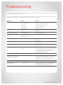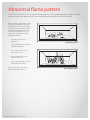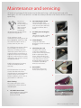
1
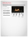
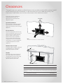
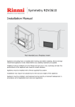
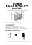
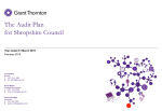
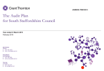
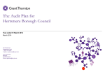
Operation guide
Symmetry RDV3611
Important:
The Symmetry RDV3611 is recommended for a new build installation into
a false (mock) chimney. It is not suitable for retrofitting into an existing
masonry fireplace.
Appliance must be installed with a Rinnai approved flue system.
This appliance shall be installed in accordance with:
-- Manufacturer’s installation instructions
-- AS/NZS 5601
-- Local regulations and municipal building codes
Installation, servicing and repair shall be carried out only by authorised
personnel.
Please retain this manual for future reference.
WARNING
Improper installation, adjustment, alteration, service or maintenance can
cause property damage, personal injury or loss of life.
For more information about buying, using, and servicing of Rinnai
appliances call: 0800 RINNAI (0800 746 624).
Rinnai New Zealand Limited
105 Pavilion Drive, Mangere, Auckland
PO Box 53177, Auckland Airport, Auckland 2150
Phone: (09) 257 3800, Fax: (09) 257 3899
Email: [email protected]
Web: www.rinnai.co.nz, www.youtube.com/rinnainz
:
s
t
n
e
cont
Introduction................................................................4
Safety...........................................................................5
Clearances...................................................................6
General information....................................................7
Wireless controller......................................................8
Wireless controller display..........................................9
Operation of your RDV3611..........................................10
Modes of operation.....................................................11
Programming your controller.....................................12
Operation using your controller.................................13
Operation without the controller...............................14
Troubleshooting..........................................................15
Abnormal flame pattern..............................................16
Maintenance and servicing.........................................17
Commissioning ...........................................................18
Limited Warranty.........................................................19
Introduction
Blending style with innovation
Symmetry RDV3611
By installing a Rinnai Symmetry
RDV3611 you can be confident that
you are choosing an incredibly
efficient and safe heating source
for your home.
Gas
consumption
19-33 MJ/h
(low to high)
Output
3.8-7.5 kW
Efficiency
80%
7.5 kW heat
output will warm
up large areas
Ceramic
liners provide
additional radiant
heat
Heat additional
rooms in your
home with heat
ducting capacity
4 | RDV3611 Operation Guide: 11158-B 02-13
Venting can be
installed vertically
or horizontally
Convection fan
helps circulate
heat more
efficiently
Large landscape
window provides
a great view of
the fire
Direct vent
technology
uses outside
air to create a
healthy living
environment
Ember bed glow
of the burner
creates one of
the most realistic
looking fires
Safety
Important
WARNING
This appliance is not intended for use by persons (including children) with
reduced physical, sensory or mental capabilities, or lack of experience and
knowledge, unless they have been given supervision or instruction concerning
use of the appliance by a person responsible for their safety.
-----
The heater must not be used if the glass or panels are damaged
Do not place articles on or against this appliance
Do not use or store flammable materials near this appliance
Do not modify this appliance
--
Do not spray aerosols in the vicinity of this appliance while it is in operation
Do not restrict warm air discharge
by placing articles in front of the
appliance.
This appliance must not be used
for any other purpose other than
heating.
Do not allow anyone to sit, lean
or sleep directly in front of the
appliance.
Do not allow curtains or other
combustible materials to come
into contact with the appliance.
Children should be supervised at
all times to ensure they do not play
with the appliance. Hand or body
contact with the appliance must
be avoided.
Do not unplug the appliance
while it is operating. Do not use
power boards or double adaptors
to operate this appliance.
RDV3611 Operation Guide: 11158-B 02-13 | 5
Clearances
The appliance must not be installed where curtains or other combustible materials could
come into contact with the heater. In some case curtains may need restraining. The
clearances listed below are minimum clearances unless otherwise stated.
Due to the number of different
sized Symmetry frames, all
dimensions are taken from the
edge of the glass.
1000
To ceiling
400
Up-wall installations
If the Symmetry is being installed
up the wall, the recommended
minimum clearance to the ceiling is
1000 mm.
Floor protection
Heat emanating from this fire may
over time affect the appearance of
some materials used for flooring,
such as, carpet, vinyl, cork or
timber. This may be amplified if
the air contains cooking vapours
or cigarette smoke. To avoid this
occurring, it is recommended that
a mat be placed in front of this
appliance.
400
400
1
0
0
0
Note
The 400 mm side clearance includes side walls.
Mantels and surrounds
A mantel and surround are allowed
providing they are outside the
minimum clearances shown.
B - Mantel depth
Hearths
A hearth is not necessary but can
be used for decorative purposes
or protection of sensitive flooring
if required. A hearth must not
obscure the front of the fire.
A - Mantel height from top of glass
D - Surround
projection
C - Surround from side of glass
A
Mantel height from top of glass
400 mm min.
B
Mantel depth at A - 400 mm (vertical clearance)
250 mm max.
For every 50 mm of added mantel depth, there must be an additional 100 mm of vertical
clearance. For example; a mantel depth (B) of 350 mm will require 600 mm (A) of vertical
clearance.
6 | RDV3611 Operation Guide: 11158-B 02-13
C
Surround from side of glass
250 mm min.
D
Surround projection at C - 250 mm (side clearance)
250 mm max.
General information
Before operation please read these instructions to get an overview of how to operate,
maintain and service your Rinnai gas fire.
Cladding and finishes
The Symmetry RDV3611 comes in
two framing options; framed and
frameless. Framed is best suited
to a dry wall/plaster finish. The
frameless option suits cladding
with a finished edge, such as, tiles,
brick, or polished granite.
With a framed and frameless
installation the fire is a permanent
fixture. The fire is screwed to the
framing before the cladding. Once
the cladding has been fixed in
place the Symmetry RDV3611 has
been framed into a permanent
position.
The depth of the Symmetry
RDV3611 is adjustable to
accommodate a range of cladding
options. This is important for a
frameless installation to achieve
a flush finish. Where the edge is
visible, an aluminium edge can be
used to hide the visible cladding.
Electrical connection
The standard
electrical
connection is to
the right hand side
of the heater front
assembly. If necessary this can be
changed by your electrician to
terminate on the left.
The connection is either direct
wired or connected to a power
point within the cavity. A 1500 mm
power cord is supplied with a 3-pin
plug. This must be connected to
a dedicated earthed power point.
The electric isolation switch must
be accessible after the appliance
has been installed.
The heater must not be located
immediately below a socket outlet
(potential fire hazard).
If the supply cord is damaged, it
must be replaced by a licensed
tradesperson. This must be a
genuine replacement part available
from Rinnai, part number 6765B.
Heat transfer kit
The heat transfer ducting
kit is available as an optional
accessory. This allows heat from
the Symmetry RDV3611 to be
transferred to another area of the
house.
It is best to install the kit at the
same time as the fire due to the
additional space required for
installation. The heat transfer kit
must be installed by a licensed
tradesperson.
Installation by a licensed
tradesperson
Ensure your installer talks to you
about the use and care of this
appliance, and that you understand
these instructions. The installer
also needs to complete the
appliance commissioning sheet
and installer details, and leave this
guide with you.
Soot deposits
Small soot deposits on the log set
or glass is normal. Significant build
up however is not normal and will
require a service call. Refer to the
troubleshooting section for further
information.
TV installation above the
fireplace
If installing a flat
screen TV above the
fire the main issue is
heat. Heat from the
fire and heat from the
flueing components that sit behind
the TV, especially if recessed.
The Symmetry RDV3611 has a fan
that distributes warm air from the
top of the appliance out into the
room. As warm air is dispersed
outwards as opposed to directly
upwards, installation of a TV may
be an option.
For further information please
contact Rinnai or refer to the
installation manual. This illustrates
recommended minimum
clearances when installing a TV
directly above the Symmetry
RDV3611 or into a recess.
Safety devices
Your Rinnai Symmetry RDV3611 is
designed with the following safety
devices:
-----
light to pilot
overheat safety switch
flame failure
combustion chamber pressure
relief
RDV3611 Operation Guide: 11158-B 02-13 | 7
Wireless controller
Your wireless controller is designed to be wall mounted on a bracket, supplied with the
controller, within 10 m of the fire.
How it operates
The controller houses the
thermostat that senses the room
temperature and communicates
information back to the Symmetry
RDV3611 via radio frequency.
It needs to be positioned in the
same room as the Symmetry
RDV3611 and the area that requires
heating—a place not subject
to temperature fluctuation.
For example; if placed near a
door subject to cold drafts, the
controller will sense the room
is much colder than it is and the
RDV3611 will keep heating the
room, when in reality the set
temperature has been reached.
Controller position
The ideal position for the
controller is:
-- away from possible drafts in
the room
--
away from direct sunlight
--
a suitable distance away from
the heater, approx. 2-10 m
--
ideally 1.5 m from the floor
(approx. at chest height when
standing)
Controller dimensions
Height: 140 mm
Width: 80 mm
Depth: 20 mm
Battery
Type: 2 x AA batteries
Life: Approx. 12 months
When the batteries are changed
all settings will be lost and the
controller will revert back to the
initial setup screen.
8 | RDV3611 Operation Guide: 11158-B 02-13
Handy tips
The most efficient way of
operating your Symmetry RDV3611
is with the wireless controller.
Once the unit has been turned
on at the wall for the first time,
and the ON button pressed on
the unit’s control panel, use the
wireless controller to turn the unit
on and off (not the button on the
appliance).
If you turn the appliance on with
the button on the control panel,
make sure the wireless controller
is also turned on (otherwise the
appliance will turn itself off).
If you do turn the appliance off
with the button on the appliance
you will need to turn it on again
with the button on the appliance—
you won’t be able to turn it on with
the remote.
If the appliance is not going and
the LED, on the control panel, is
permanently on, push the ON/OFF
button next to the LED twice to get
the appliance to re-ignite.
If the LED on the appliance is
off check the flame symbol on
the wireless controller; if it is
pulsing, the appliance is still on
and will relight when the room
temperature drops.
Wireless controller display
Transmit indicator
Indicates the wireless controller is transmitting to the
receiver. The symbol will appear for in the LCD for
one second.
Battery indicator
Symbol will flash when batteries
need replacing. The wireless
controller will remain functional
for approximately five days before
shutting off.
Temperature display
Displays the current room
temperature.
Flame indicator
Indicates flame height. When in
manual or automatic modes, the
heater will switch off if the room
temperature reaches the set
temperature. When this occurs,
the flame indicator will rise and fall
every few seconds to indicate the
RDV3611 is still operational.
Set temperature indicator
When the wireless controller
is on, the programmed
temperature will only be
displayed. In flame mode, only
the flame setting (F1-F7) will
display.
Time of day and day of week
Operation mode indicator
When in flame mode, the display
will be blank.
Mode button
Toggles between automatic,
manual, and flame modes.
T - Time
Initiates the time and day of the
week programming. Press and
hold for two seconds.
UP
A/M
T
OK
P
PWR
DOWN
Power button
PWR and OK pressed together
switches the wireless controller
on—child lock safety feature. PWR
switches the controller off.
P - Program
Indicates programming mode.
Press and hold for two seconds.
UP, OK, DOWN
UP/DOWN: Changes hours, minutes, day or
temperature.
OK: Accepts the current function and advances the
next function.
RDV3611 Operation Guide: 11158-B 02-13 | 9
Operation of your RDV3611
Your controller has a built-in child lock function that requires pressing two buttons
simultaneously. This function cannot be overridden. To turn the controller on, press PWR
and OK at the same time. Pressing PWR will switch the controller off.
Fan
On start-up, the fan will start
approximately four minutes after
the heater is switched on. This
delay is to reduce the amount of
cold air being pushed out into the
room.
On shut-down, the fan will stop
approximately eight minutes after
the heater is switched off. This is to
cool the appliance down.
Modes of operation
Your RDV3611 has three modes of
operation:
----
Manual (set temperature)
mode
Automatic (programmed timer
and temperature) mode
Flame control mode
IMPORTANT
The RDV3611 is designed to run as
efficiently as possible.
When in manual or automatic
modes, the heater will switch
itself off if the room reaches the
set temperature, i.e. in smaller
rooms that heat up quickly. When
this occurs, the flame indicator
on your controller will rise and fall
every few seconds to indicate the
RDV3611 is still operational. The
heater will restart again once the
room temperature falls below the
set temperature.
ALWAYS check your wireless
controller before going to bed or
leaving the building to ensure the
heater has been switched off.
If you want the RDV3611 to operate
regardless of room temperature,
10 | RDV3611 Operation Guide: 11158-B 02-13
you can adjust the controller to
flame control mode only.
Start-up
When turning the RDV3611 on, the
heater will automatically go to the
highest setting for approximately
45 seconds—this is to establish the
flame pattern. You can adjust the
heater during this period, but there
will be a 45 second delay.
Over temperature automatic
shut off
The controller when operating
in any of the three modes will
automatically shut down and
switch the heater off if the room
temperature exceeds 40 °C for
more than three minutes—this is a
safety feature.
Modes of operation
Manual
Automatic
Flame control
--
Temperature can be set at any
level.
--
Temperature is regulated to a
programmed level and time.
--
Time and day of week does not
need to be set.
--
Time and day of week needs to
be set.
Allows you to set your preferred
flame setting and override the set
temperature—your heater will not
automatically turn itself off (unless
the room exceeds 40 °C).
With the controller turned on,
press and release the A/M button
until the word ‘MANUAL’ appears
on the LCD. Press and hold the ‘UP’
and ‘DOWN’ buttons to increase/
decrease the temperature by 1 °C.
--
At any time the temperature
may be adjusted up or down.
To activate the flame mode:
1. Turn the controller on (PWR +
OK)
2. Press the A/M button until
the MANUAL or AUTO symbol
disappears from the bottom of
the LCD.
3. The LCD will display what is
shown in the image below.
Use the UP and DOWN button
to adjust the flame setting
(seven flame stages in total).
When using for the first time,
the controller will default to
F1 (lowest setting), and then
default to the last selected
flame setting when used again.
1
2
UP
A/M
T
OK
P
PWR
DOWN
1. Flame setting
Flame symbol will correspond to
the flame setting selected—F7-F1
(highest to lowest).
2. Flame mode
Nothing will be displayed in this
window when operating in flame
mode.
RDV3611 Operation Guide: 11158-B 02-13 | 11
Programming your controller
The clock must be set before the programmed timers will operate. Each day of the week
can be programmed for four periods, making a total of 28 programmed periods.
Setting the clock
1. With the controller (heater)
off, press T for two seconds.
2. Using the UP and DOWN
buttons adjust to the correct
time. Ensure you have the
correct time of the day (AM/
PM). Press OK to accept.
3. Repeat process to adjust the
minutes and day of the week.
UP
A/M
T
OK
P
PWR
DOWN
DEFAULT SETTINGS
Time
period
Start time
Temp. °C
Period 1
6.00 am
20 °C
Period 2
8:30 am
15 °C
Period 3
5:00 pm
21 °C
Period 4
10:30 pm
15 °C
If you would like to stop the heater
from coming on at all, for example,
during the night and before period
1, you can reduce the temperature
setting using the DOWN button
until –– °C is reached. This means
no set temperature has been
programmed, and your heater
will stay off until the next period
setting.
For example:
Week settings available
MO > TU > WE > TH > FR >
MO TU WE TH FR > SA > SU >
SA SU > MO TU WE TH FR SA SU
A weekday program can be set
so the program is used Monday
to Friday. Similarly, a weekend
program can be set for Saturday to
Sunday.
If you do nothing to change
the programming the default
settings would be available if you
set it to automatic mode. When
in this setting, the heater will
automatically turn itself on and off
depending on the temperatures
set (similar to an air conditioning
unit).
For example:
If the room temperature at 1 am
falls below 15 °C, the heater will
turn on and stay on until the room
temperature increases above 15°C.
12 | RDV3611 Operation Guide: 11158-B 02-13
Time
period
Start time
Temp. °C
Period 1
5.30 am
20 °C
Period 2
8.00 am
15 °C
Period 3
5.30 pm
20 °C
Period 4
11:30 pm
- - °C
To revert back to the default
settings, press the following
sequence of buttons:
P > T > T > DOWN
To begin programming
With the controller off, press and
hold the ‘P’ button for two seconds
to initiate programming. The LCD
will display ‘PROG’, ‘Pd’ and the
time at which the controller is
currently set will flash. Period 1 can
now be set.
Setting the day of the week
1. Press and release the ‘UP’ or
‘DOWN’ button to change
the day of the week. Scrolling
order is as follows:
MO > TU > WE > TH > FR
> SA > SU > SA SU > MO
TU WE TH FR SA SU
2. To accept the selected day(s)
of the week press OK.
Setting the period starting time
1. After setting the day the AM/
PM settings will flash. To set
the P1 starting time, press and
release the ‘UP’ or ‘DOWN’
button for the hour setting.
Ensure that the AM/PM is set
correctly.
2. To accept press OK. The
minute setting will now flash as
in step 1—press OK to accept.
Setting the temperature
1. After setting the time period
the temperature will flash.
Press and release the ‘UP’
or ‘DOWN’ button for two
seconds to adjust.
2. To accept press ‘OK’. Period
one is now set for the day(s)
of the week you have chosen.
The LCD will display P2 to
indicate period 2, which can
now be set for the same day(s)
of the week.
3. Repeat programming process
for remaining periods.
If you want to check what has
been programmed, press P
for two seconds and select OK
continuously to cycle through the
settings for each period.
Operation using the controller
The wireless controller will be factory set so synchronising will only be necessary if there
is an error, or if the controller has been purchased separately.
Synchronising involves the wireless
controller sending a signal to the
fire so that it can memorise the
certified frequency that it operates
on.
If the controller is not
synchronised
Only perform if the wireless
controller is not synchronised
(heater will not operate when any
of the functions are selected on
the controller).
1. Turn the power off at the
power point for a minimum of
30 seconds, synchronisation
will not be possible unless the
minimum 30 seconds has been
observed.
2. Ensure the wireless controller
is turned off (to turn off press
the PWR button once).
3. Turn the power on at the
power point, the operation
indicator on the push button
control panel will flash.
The controller can now be
synchronised with the heater.
Synchronisation MUST BE
performed within 30 seconds
of the power being turned on.
If more than 30 seconds has
elapsed repeat steps 1-3.
4. With the controller still off,
press the following sequence
of buttons in quick succession:
P > T > T > UP
The LCD display will show LC
(Learn Code) for two seconds
then return to the normal
OFF state display. During
this time a special code will
be transmitted by the RF
controller to the heater. The
operation indicator on the
push button control panel
will flash to indicate that the
synchronisation has been
accepted.
Turning on and off
Press the ‘OK’ and ‘PWR’ button at
the same time to ignite the heater.
This is a safety feature to reduce
the chance of young children
being able to turn on the unit.
The unit first lights to pilot and
then after a period switches to the
high setting.
Changing between °C and °F
The thermostat display can be set
to °C and °F. The default setting is
°C.
With the thermostat off, press the
following sequence:
P > T > T > A/M
To restore the factory default
settings
To restore the factory default
settings (with the controller still
OFF), press the following sequence
of buttons:
P > T > T > DOWN
To turn off, press and release the
‘PWR’ button.
Changing the temperature
The Symmetry RDV3611 has seven
stages of temperature/flame
modulation which can be changed
using the ‘UP’ and ‘DOWN’
buttons.
Your temperature control range is
7-32 ˚C.
There is also a setting before
7 ˚C that is - - °C. This means
no set temperature has been
programmed.
UP
A/M
T
OK
P
PWR
DOWN
NB: The 7 °C setting does not
indicate cooling functionality.
The lower temperature range is
for cooler climates where room
temperatures fall below 7 °C.
Changing between modes
To change between manual,
automatic, or flame mode, press
and release the A/M button.
RDV3611 Operation Guide: 11158-B 02-13 | 13
Operation without the controller
If you lose your controller, or the batteries go flat, you can still operate your unit using
the control panel on the appliance.
Models with the control panel on the lower right hand
side
Press and release the ON/OFF button. This will
start the electronic spark and the Power LED will be
permanently illuminated. The pilot will ignite first and
then automatically go to the high setting (stage four
modulation). Pressing the ON/OFF button again will turn
the unit off.
Under gas failure conditions, the appliance will go into
lock out after sparking for one minute. Under lock out the
Power LED will remain illuminated. To start the appliance
again, press and release the ON/OFF button twice after
gas supply resumes.
Red power LED ON/OFF button
In the event of a power failure the Symmetry RDV3611 will
turn off and will need to be manually turned on again when
power is restored. This is a safety feature.
Models with the control panel on the side (premium
frame)
Turning the heater on
Press the ON/OFF button once, you will hear the
electronic ignition sparker. The electronic ignition stops
when the pilot flame is established, the main burner then
ignites off the pilot and will go to the highest setting. The
blue LED power indicator will stay on, indicating the heater
is in operation. Flame height may be adjusted after one
minute of operation.
To change the burner and fan settings press the UP and
DOWN arrows to increase or decrease the flame height.
Turning the heater off
Press the ON/OFF button once. The blue LED power
indicator will turn off indicating that the appliance is in the
off position.
LED indicators
On
= blue
Standby= red
Off
= nothing
14 | RDV3611 Operation Guide: 11158-B 02-13
ON/OFF button
Blue LED indicator
Increase
Decrease
Troubleshooting
During installation there will be an initial burning in period where some smoke and smell may be experienced.
This is a normal part of the operation.
The appliance is fitted with an overheat safety switch. Under overheating conditions this switch will shut off the
appliance. If the appliance shuts off repeatedly servicing may be required.
Symptom
Cause
Solution
Burner will not light
No power present
No gas present
Power cut
Air in gas pipe
Ignition failure
Ensure power cord is plugged in and turned on.
Ensure gas supply is turned on.
Re-ignite after power is restored.
Purge air (installer to do).
Repeat ignition steps.
Smell of gas
Leaking gas
Turn off gas at meter or LPG cylinder and call your
installer.
Small soot deposit on logs
Normal operation
No action required.
Severe soot deposits forming
on logs or glass
Inadequate flue system,
incorrect gas pressure or log
misalignment
Contact a Rinnai Service Centre.
Condensation on glass
Normal operation
Allow heater to warm up and condensation will
disappear.
Fire comes on at the wrong time
Program not set correctly
Check program periods and AM/PM is correctly
set on controller.
Controller display blank
Flat batteries
Check batteries are in place correctly, or replace
with new batteries.
Heater keeps turning itself off
Set room temperature has been
reached
Normal operation, heater has turned off as the
room has reached the set temperature. If you wish
to override this and have the heater continually
on, revert to flame mode, or increase set
temperature (maximum 32 °C).
Models with the control panel on the bottom
Red power LED light is on but
the heater isn’t going and the
controller doesn’t work
Indicates fault mode
Press the ON/OFF button on the control panel
once (the red LED will flash), press again and the
red LED will stay on and the heater will attempt to
re-ignite. Your controller should now work.
Models with the control panel on the side (premium frames)
Blue LED light is on but the
heater isn’t going
Indicates fault mode
Press the ON/OFF button once (the blue LED will
flash), press again and the blue LED will stay on
and the heater will attempt to re-ignite.
RDV3611 Operation Guide: 11158-B 02-13 | 15
Abnormal flame pattern
Each Rinnai Flame Fire has a distinct flame pattern. This should look the same every time
you start your fire, after an initial warm up period of approximately 20 minutes.
Abnormal flame performance and/
or pattern can indicate a problem
with your fire, such as blocked gas
injectors, or that the log set (burn
media) has shifted from when the
fire was first installed. There are
some warning signs that could
indicate a problem.
--
Unusual smell from the
appliance
Normal flame pattern
--
Continued difficulty or delay in
establishing a flame
--
Flame appears either very
short or very long
--
Flame only burns part way
across the burner
--
Severe soot building up on the
inside of the glass door
If any of the above signs occur,
please call Rinnai to discuss.
16 | RDV3611 Operation Guide: 11158-B 02-13
Abnormal flame pattern
Maintenance and servicing
All external surfaces of the heater can be cleaned using a soft damp cloth and mild
detergent. DO NOT use solvents and do not attempt to clean the heater while it is hot or
operating.
Rinnai has a
maintenance/
service and spare
parts network
with personnel
who are fully
trained and
equipped to give the best advice
on your Rinnai appliance.
If your appliance needs
maintenance/servicing, please call
Rinnai (0800 746 624) from a land
line and select option one for a
service centre in your area.
For reliable operation Rinnai flame
fires should be serviced every
two years, including inspection
of the flue system. If they are in a
particularly dusty environment or
subject to excess lint, for example
dog hair, or where there are newly
laid carpets, then annual servicing
would be beneficial.
Regular maintenance/servicing
is not covered by the Rinnai
warranty.
Do not attempt to carry out any
service work other than that
mentioned in the troubleshooting
section. If you have any other
faults or problems, please refer to
your installer or call Rinnai.
2. Unscrew the glass frame
Unscrew the four outer
screws. DO NOT remove the
inner screws as this will cause
the glass to fall out of the
frame.
3. Carefully remove the glass
frame
Lift from the top tab—pulling
the glass out and then off.
1.
2.
4. Clean the glass
Using a dry and mild
detergent, clean the inside of
the glass.
5. Check the glass seal
The glass seal is critical
to the safe and effective
performance of the appliance.
Before replacing the glass
frame, check the glass seal
to ensure there is a complete
seal, and no part is worn or
damaged. If damaged it will
need to be replaced by a
Rinnai Service Centre.
3.
4.
6. Reassemble
Reattach the glass inner
frames to the Symmetry.
5.
Glass cleaning
The inside of the glass can be
cleaned using a clean cloth and
mild detergent.
1. Lift off the inner frame
Pull the bottom section off the
lower magnets, and lift the
frame up and off.
Example of a damaged glass seal
RDV3611 Operation Guide: 11158-B 02-13 | 17
Commissioning
The installer must complete the installation and commissioning checklist below and
make sure this guide is left with you. They must also instruct you in the use and care of
the Symmetry, and make sure you understand the safety instructions and operation of
the appliance.
Checklist
FF Appliance positioned in a suitable location (clearances etc.).
FF Rinnai flue system installed and tested to ensure effective draw.
FF Uprating kit installed if an LPG installation with a vertical termination.
FF Gas pressure checked and set.
FF Burn media installed as per instructions.
FF Appliance tested for correct operation and to ensure no gas leaks.
FF Customer instructed on operating procedure and safety requirements.
Installer details
Company name:
Installer name:
Address:
Phone:Mobile:
Certificate of compliance number for installation:
Signed:Date:
18 | RDV3611 Operation Guide: 11158-B 02-13
Limited Warranty
Rinnai brings you peace of mind with a:
2 Year minimum warranty
Terms and conditions
1. During the 24 month period from date
of purchase and subject to clauses 2 and
3 below, Rinnai New Zealand Limited
(“Rinnai”) will, at its own discretion, either
replace or repair any defective product at
no charge to the customer.
2. This warranty covers manufacturing
defects only. This warranty will not apply
if (for example) the product has been
improperly installed or is otherwise
installed contrary to manufacturer’s
recommendations, has been damaged
during or after installation, has not been
operated in accordance with operating
instructions, or has been subjected to
damage or abuse beyond that expected
from conditions of normal use.
3. Warranty claims may be invalid if not
accompanied by details of the installing or
supervising gas fitter’s registration number
and the gas fitting certification number.
the time of any warranty claim.
5. Servicing of the product is to be carried
out by a Rinnai authorised service centre.
All Rinnai appliances meet or exceed the
safety standards required by New Zealand
gas and electrical regulations. The company
is constantly improving its products and as
such specifications are subject to change or
variation without notice.
4. T his warranty commences from the date of
purchase. Proof of purchase is required at
RECORD YOUR DETAILS
OF PURCHASE BELOW:
ATTACH YOUR PROOF OF
PURCHASE HERE:
Retailer:
Retailer address:
Date of purchase:
Product details:
Please keep these details in a safe place for future reference.
RDV3611 Operation Guide: 11158-B 02-13 | 19
Experience our innovation
Rinnai.co.nz 0800 746 624
http://www.youtube.com/rinnainz