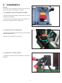
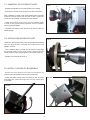
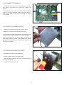
1
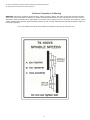
Mini Lathe
Speed
MiniVariable
Lathe Speed
KitKit
Owner’s Manual
Model:
79-100VS
Model:
79-100VS
(Designed
to Fit Model
#70-100 Minionly)
Lathe)
(Available
for Model#70-100
Record the serial number and date of purchase
in your manual for future reference.
Serial number:
Date of purchase:
For more information:
www.rikontools.com or [email protected]
For Parts or Questions:
Part # 70-200EVSM1
Part #79-100VSM2
[email protected] or 877-884-5167
Index
1. GENERAL INFORMATION
1.1 FOREWORD
2.
2.1
2.2
2.3
2.4
2.5
2.6
MACHINE DESCRIPTION
COMPONENTS
RECOMMENDED PROTECTIVE CLOTHING
NOISE EMISSION
PRESCRIBED USE OF THE MACHINE
HAZARDS
SAFETY INSTRUCTION FOR MINI LATHE
3. INSTALLATION
3.1 UNINSTALL THE OLD SWITCH PLATE
3.2 UNINSTALL THE TERMINALS
3.3 UNINSTALL STRAIN RELIEF
3.4 UNINSTALL BELT AND MOTOR
3.5 UNINSTALL THE OLD MOTOR PULLEY AND MOUNTING PLATE
3.6 INSTALL MOUNTING PLATE AND NEW MOTOR PULLEY TO NEW MOTOR
3.7 UNINSTALL OLD SPINDLE PULLEY
3.8 INSTALL NEW SPINDLE PULLEY
3.9 INSTALL THE NEW PC BOARD BOX
3.10 CONNECT TERMINALS
3.11 FIX PC BOARD TO BOX
3.12 INSTALL NEW SWITCH PLATE
3.13 WIRE CONNECTION TO SWITCH
3.14 INSTALL SWITCH PLATE TO HEADSTOCK
2
1. General Information
1.1
FOREWORD
This manual must be read and understood before operating the machine. This will provide a better
working knowledge of the machine, for increased safety and to obtain the best results.
2. Machine Description
2.1 When
opening
find
thebelow
components
shownDon't
below.
Don't
2.1
While
open the
the package
package ofofthe
theSpeed
SpeedKit,
Kit,you
youwill
will
find
components.
start
to
start
to
assemble
the
Speed
Kit
if
any
components
are
missing.
assemle the Speed Kit if any component missing.
1
2
3
6
5
1
Motor Pulley
2
Spindle Pulley
3
Switch plate
4
Pc Board with box
5
Motor
6
Spare parts bag
4
3
3
2.2 RECOMMENDED PROTECTIVE CLOTHING
•
•
•
•
Non-slip footwear is recommended.
Do not wear loose clothing, neckties or jewellery; they can be caught in moving parts.
Roll up long sleeves above the elbow.
Wear protective hair covering to contain long hair.
2.3 NOISE EMISSION
The measurements of noise, in the working position and during operation, were carried out under the standard ISO 7960 Annex B and C:
Instantaneous acoustic pressure:
Sound power level(no load)
<98dB(A)
Sound power level(load)
<107dB(A)
Sound Pressure level(no load) <89dB(A)
Sound Pressure level(load)
<98dB(A)
Constant K=4 dB measured in accordance with EN ISO 3746:1995
The figures quoted are emission levels and are not necessarily safe working levels. Whilst there is a correlation between the emission
and exposure levels, this cannot be used reliably to determine whether or not further precautions are required. Factors that influence
the actual level of exposure of the workforce include the characteristics of the work room and the other sources of noise etc. i.e.
the number of machines and other adjacent processes. Also the permissible exposure level can vary from country to country. This
information, however, will enable the user of the machine to make a better evaluation of the hazard and risk.
2.4 PRESCRIBED USE OF THE MACHINE
This machine is intended for turning between centers and face plate turning of solid woods. The permissible workpiece dimensions
must be observed (see Technical Specification).
Any other use is not as specified. Unspecified use, modification of the machine or use of parts not tested and approved by the
equipment manufacturer can cause unforeseen damage.
2.5 HAZARDS
ATTENTION Mini lathe still present risks that cannot be eliminated by the manufacturer. Therefore the user must be aware that wood
working machines are dangerous if not used with care and all safety precautions adhered to.
2.6 SAFETY INSTRUCTIONS FOR MINI LATHES
A mini lathe is a tool which due to operator carelessness, cause serious personal injury. It is therefore strongly recommended you
read and observe:
1. Do not operate this machine until you have read all of the following instructions.
2. Do not attempt to operate this machine until it is completely assembled.
3. Do not turn ON this machine if any pieces are missing.
4. If you are not familiar with the operation of the machine, obtain assistance from a qualified person.
5. It is highly recommended that this machine be firmly mounted to a flat and secure work surface.
6. Always wear protective eyewear prior to operating this machine.
7. Do not operate this machine if you are under the influence of drugs and/or alcohol.
8. Remove all jewelry prior to operating this machine.
9. Do not wear any gloves while operating this machine.
10. Always make sure the power switch is in the OFF position prior to plugging in the machine.
11. Always make sure the power switch is in the OFF position when doing any assembly or setup operation.
12. Always turn the power switch to the OFF position and let the work piece come to a complete stop prior to removal.
13. Use only sharp lathe tools.
14. The use of any accessories or attachments not recommended may cause injury to you and damage your machine.
15. This machine must be properly grounded.
16. When turning between centers, make sure headstock and tailstock are snug against work piece.
17. When face plate turning, rough-cut work piece close to the finished shape before screwing to face plate.
18. Never jam tools into work piece or take too big a cut.
4
4
19. Do not operate this machine without following all these instructions.
20. Keep these instructions for future reference.
California Proposition 65 Warning
WARNING: Some dust created by power sanding, sawing, grinding, drilling, and other construction activities contains
chemicals known to the State of California to cause cancer and birth defects or other reproductive harm.Your risk from
exposure to these chemicals varies, depending on how often you do this type of work. To reduce your exposure, work in
a well-ventilated area and with approved safety equipment, such as dust masks that are specially designed to filter out
microscopic particles.
For more detailed information about California Propostion 65 log onto rikontools.com.
5
3. Installation
FIG.1
FIG. 1
CAUTION
A
B B
The machine must not be plugged in and the power switch must
A
be in the OFF position until assembly is complete.
3.1 UNINSTALL THE OLD SWITCH PLATE
PLATE
Unscrewthe
the
three
to loosen
-- Unscrew
3pcs
panpan
headhead
screwscrews
A-Fig.1,(A-FIG.1)
and then unscrew
the plate from headstock.
the small pan head screw B-Fig.1. Then take out the switch
B
plate.
- Unscrew the two small pan head screws (B-FIG.1) to
loosen the switch plate from inner black box.
B
A
3.2 ATTACHING SPUR CENTER ON THE
3.2 UNINSTALL THE TERMINALS
HEADSTOCK
FIG.2
A
B
grounding
terminal
and
-- Unscrew
Insert spurthe
center,
with a No.2
Morse (A-FIG.2)
Taper shank,
intouninstall
the
other terminals(B-FIG.2).
headstock spindle. (See FIG.2)
A
- Remove the black plastic box (C-FIG.2).
C
B
3.3 UNINSTALL STRAIN RELIEF
FIG.3
- Uninstall the two strain relief cord holders on the back of
headstock.
6
3.4 UNINSTALL BELT AND MOTOR
FIG.4
- Remove spring loaded motor locking handle.
A
- Uninstall the belt from the lathe.
- Loosen the nylon lock nut (A-FIG.4) using a 13MM
wrench then remove motor.
3.5 UNINSTALL THE OLD MOTOR PULLEY
AND MOUNTING PLATE
FIG.5
B
- To remove the motor pulley (A-FIG.5) loosen the socket
screw (B-FIG.5) with a 3mm L wrench.
A
C
- Loosen the two large socket head screws (C-FIG.5) with
5mm L wrench, then lift the mounting plate off the motor
shaft.
3.6 INSTALL MOUNTING PLATE AND NEW
MOTOR PULLEY TO NEW MOTOR
FIG.6
A
- Install the mounting plate (B-FIG.6) to the new motor, and
lock the socket head screw (D-FIG.6) with 5mm L wrench.
D
CAUTION: Pay attention to the direction of the mounting
plate compared with the new motor.
- Install the new motor pulley (A-FIG.6) to the new motor,
and lock the socket screw (C-FIG.6) with 3mm L wrench.
C
B
CAUTION: Please install the new motor pulley carefully. Do
not use excessive force avoiding breaking the new motor
pulley or damaging the motor shaft.
- Thread new motor cable through the rubber grommet in
bed casting then into the bottom hole in the strain relief
plate.
- Install the new motor assembly to your mini lathe as the
chart 3.4 shown
7
3.7 UNINSTALL OLD SPINDLE PULLEY
FIG.7
A
- Engage the spindle lock to stop spindle from rotating.
B
- Unscrew the socket screw (A-FIG.7) to take out handle.
Note: Handles on older units are threaded onto the shaft
end and held into place with one set screw. Loosen set
screw and spin handle clockwise (reverse thread).
- Older units use a snap ring to set the handle depth
in front of the spindle pulley. Remove snap ring before
removing spindle pulley.
- Unscrew the socket screw (B-FIG.7) to take out the old
spindle pulley.
3.8 INSTALL NEW SPINDLE PULLEY
FIG.8
- Slide the new spindle pulley onto the spindle shaft making
sure the large pulley is toward the handle end of the
spindle. A-FIG.8.
A
- Use a straight edge or install the drive belt to help align
the spindle pulley to the motor pulley. Tighten the two
socket screws on the spindle pulley to lock it into position.
- Install the end handle and lock it.
B
3.9 INSTALL THE NEW PC BOARD BOX
- Remove the PC board from the PC board box by
loosening the two phillips head screws (A-FIG.9A).
- Install the cable of new motor according to the old route
and slide the cables through the new PC board box
(A-FIG.9B).
FIG.9B
A
FIG.9A
A
8
3.10 CONNECT TERMINALS
FIG.10
- Connect the white wire of the motor cable to M+ position,
and connect the black wire of the motor cable to Mposition.
M+
M-
- Connect the bare copper end of the black wire (white
shown for clarity) of the power cable to the AC-IN position.
Note: It is necessary to trim the bare copper wire leaving
1/4" exposed.
3.11 INSTALL PC BOARD TO BOX
FIG.11
- Install the PC board to new box as shown in FIG.11.
- Slide the PC board box into into the lathe head.
- Due variations in casting and powdercoat thickness it may
be necessary to enlarge the switch box opening slightly.
Note: On some units it may be necessary to remove the
strain relief plate on the rear of the headstock to prevent
the wires from being pinched to allow clearance as the PC
board box is installed.
3.12 INSTALL NEW SWITCH PLATE
FIG.12
A
- Uninstall the switch from old switch plate.
B
- Install the switch into the new switch plate.
- Install the speed control knob into the new plate and lock
it with nut (A-FIG.12).
- Install the knob cap (B-FIG.12).
9
Ac-In
3.13 WIRE CONNECTION TO SWITCH
FIG.13
- Mount the green wire of the motor cable and power cable
to the grounding screw (A-FIG.13) on the switch plate.
- Insert the black and white switch terminals (B-FIG.13) to
the two switch terminal posts. The wires can be mounted
on either switch terminal post without the fear of crossing
them.
A
3.14 INSTALL SWITCH PLATE TO
HEADSTOCK
- Install the switch plate to headstock as shown in FIG.1.
- Install the two strain relief cord holders on the back of
headstock as shown in FIG.3.
10
B
11. Warranty
5-Year Limited Warranty
RIKON Power Tools, Inc. (“Seller”) warrants to only the original retail consumer/purchaser of
our products that each product be free from defects in materials and workmanship for a period
of five (5) years from the date the product was purchased at retail. This warranty may not be
transferred.
This warranty does not apply to defects due directly or indirectly to misuse, abuse, negligence,
accidents, repairs, alterations, lack of maintenance or normal wear and tear. Under no
circumstances will Seller be liable for incidental or consequential damages resulting from
defective products. All other warranties, expressed or implied, whether of merchantability,
fitness for purpose, or otherwise are expressly disclaimed by Seller. This warranty does not cover
products used for commercial, industrial or educational purposes.
This limited warranty does not apply to accessory items such as blades, drill bits, sanding discs or
belts and other related items.
Seller shall in no event be liable for death, injuries to persons or property, or for incidental,
contingent, special, or consequential damages arising from the use of our products.
To take advantage of this warranty proof of purchase documentation, which includes date of
purchase and an explanation of the complaint, must be provided.
enclosed warranty card and mail it to:
RIKON Warranty
16 Progress Rd.
Billerica, MA 01821
The card must be entirely completed in order for it to be valid. If you have any questions
please contact us at 877-884-5167 or email us at [email protected].
15
11
For more information:
16 Progress Rd.
Billerica, MA 01821
877-884-5167 / 978-528-5380
[email protected]
www.rikontools.com
Copyright RIKON Power Tools, Inc. 2009
Printed in China 9/09