1
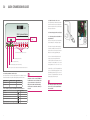
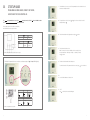
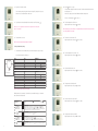
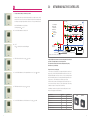
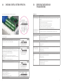
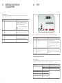
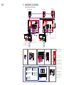
BA Master Controller
Our verbal and written application engineering advice is based upon experience and the best of our knowledge. However it is to be regarded as non-binding information.
Working conditions and use under conditions for which the product was not intended and over which we have no influence exclude any claim resulting from our information. We
recommend that a suitable check is made as to whether the REHAU product is suitable for the envisaged purpose. Application, use and processing of the products is carried out
beyond the scope of our control and are therefore carried out exclusively at your own responsibility. If liability should still apply, then this is restricted, in the case of all damage, the
value of the goods supplied by us and used by you.
Our warranty applies to the consistent quality of our products as per our specification and in accordance with our general terms and conditions of delivery and payment. This
document is protected by copyright. All rights based on this are reserved. No part of this publication may be translated, reproduced or transmitted in any form or by any similar
means, electronic or mechanical, photocopying, recording or otherwise, or stored in a data retrieval system.
Quick Installation and commissioning guide
UK & IRELAND SALES OFFICES London
REHAU Ltd
The Building Centre
26 Store Street
London
WC1E 7BT
Slough
Units 5 J & K
Langley Business Centre
Station Road
Langley
Slough SL3 8DS
Birmingham
Tameside Drive
Holford Way
Witton
Birmingham
B6 7AY
Manchester
Brinell Drive
Irlam
Manchester
M44 5BL
Glasgow
Phoenix House
Phoenix Crescent
Strathclyde Business Park
Bellshill, North Lanarkshire
ML4 3NJ
Dublin
9 St. Johns Court
Business Park
Swords Road
Santry
Dublin 9
Tel: (0207) 580 6155
Fax: (0207) 307 8595
Tel: (01753) 588500
Fax: (01753) 588501
Tel: (0121) 344 2300
Fax: (0121) 344 2301
Tel: (0161) 777 7400
Fax: (0161) 777 7401
Tel: (01698) 503700
Fax: (01698) 503701
Tel: 00353 (0)1 8165020
Fax: 00353 (0)1 8165021
www.rehau.co.uk
954600EN/XXX/E&T/06.08
www.rehau.co.uk
Building Solutions
Automotive
Industry
BA Master controller
1.0
Control System first fix
Index
1.0 .
1.1 .
1.2 .
1.3 .
.
.
.
.
.
.
.
.
.
.
.
.
.
.
.
.
. Control System First Fix
. Cable Sizes . . . . . .
. Connecting Sensors. . .
. Net Extension Kit . . . .
.
.
.
.
.
.
.
.
.
.
.
.
.
.
.
.
.
.
.
.
.
.
.
.
.
.
.
.
.
.
.
.
.
.
.
.
.
.
.
.
.
.
.
.
.
.
.
.
.
.
.
.
.
.
.
.
.
.
.
.
.
.
.
.
.
.
.
.
.
.
.
.
.
.
.
.
.
.
.
.
.
.
.
.
.
.
.
.
.
.
.
.
.
.
.
.
.
.
.
.
3
3
3
3
2.0 .
2.1 .
2.2 .
2.3 .
2.4 .
.
.
.
.
.
.
.
.
.
.
.
.
.
.
.
.
.
.
.
.
. Quick Commissioning Guide . . . . . . . . . . .
. Determining the Master Controller Required . . . . . .
. The Default (factory) Settings on the BA Master Controller.
. Setting the Channels on the Sensors . . . . . . . . .
. CT Set Up Guide . . . . . . . . . . . . . . . . .
.
.
.
.
.
.
.
.
.
.
.
.
.
.
.
.
.
.
.
.
.
.
.
.
.
.
.
.
.
.
.
.
.
.
.
.
.
.
.
.
.
.
.
.
.
.
.
.
.
.
.
.
.
.
.
.
.
.
.
.
4
4
4
5
6
Please note this system only requires Bell wire or Cat 5 cable for
wiring of controls, saving time and money.
1.1 Cable Sizes
Planned position of main
heating switch fuse spur
to main control unit
1mm2 two core & earth
Detail B on wiring
schematic (Mains)
1mm2 two core & earth
Please refer to wiring
schematic
3.0 . . . . . . Networking Multiple Controllers. . . . . . . . . . . . . . . . . . . . . .15
Control unit to FH
circulating pump.
Or to the connector
block if using a compact
mixer unit
1mm2 two core & earth
4.0 . . . . . . Checking Control System Operation . . . . . . . . . . . . . . . . . . . .16
Wiring to main system
boiler controls
Detail B on wiring
schematic
5.0 . . . . . . Error/Fault Messages and Troubleshooting . . . . . . . . . . . . . . . . .17
Room Sensor wiring
(serial or star)***
0.25mm2 two core, no
earth
Please refer to wiring
schematic
Control unit to actuator
(if more than 1m away)
1mm2 two core, no earth,
max length 40m
Detail C on wiring
schematic
6.0 . . . . . . Reset . . . . . . . . . . . . . . . . . . . . . . . . . . . . . . . . .21
6.1 . . . . . . Installation Information for REHAU Intelligent Controls. . . . . . . . . . . . . . .21
7.0 . . . . . . Wiring Schematic . . . . . . . . . . . . . . . . . . . . . . . . . . . .23
1.3 Net Extension Kit
2. Net extension kit
***It is recommended that different coloured cables are used for the 5v bus connection
of the sensors and the BA Master Controller. Care must be taken to ensure correct
wiring connection between Sensors & Controller terminals. If wires of the same colour
are used it is very likely to get the polarity wrong.
Planned Main Control Unit position to
Add On Module
(If more than 0.3m apart)
1 Net Extension Kit
REHAU Art. No. 202239
When networking multiple controllers a
Net Extension Kit is required
e.g. Networking 3 Master Controllers
(BA) requires 2 Net
Extensions Kits
REHAU Art. No. 202239
All REHAU control systems must be installed:
- By a competent person
- In accordance with the latest issue of instructions supplied with each component
- According to the current IEE wiring regulations laid out in BS 7671 and National Valid regulations and in
compliance with the ordinaries stipulated by local power authorities.
1.2 Connecting Sensors
This system does not require star wiring, Daisy Chain is only required.
This would reduce installation time and costs.
RJ 45 Connection
RJ 45 Connection
BA
Master
Add On
Module
NET EXTENSION KIT
(Required if Add On module is more than
0.3m apart from the master controller)
Please note this is a quick Installation and Commissioning guide only, for any detailed information,
please refer to REHAU Intelligent BA Heating/Cooling Controls, Technical and Installation Manual.
3. Connecting extension modules
ADD ON MODULE
MASTER
5
1
4
2
10
6
7
3
1. Star and Series cable layouts
2
9
8
SENSORS CONNECTED IN STAR
ADD ON MODULE
MASTER
1
6
5
11
7
2
3
4
8
9
10
SENSORS CONNECTED IN BUS MODE (DAISY CHAIN)
3
2.0
Quick commissioning guide
2.3 Setting the channels on the sensors
This is important because without setting the right
channel/zone number on the sensor, heating in the
related zone would not work. To carry this out please
follow the procedure below.
BA
2.3.1 Remove the top plate of the sensor (Fig. 5.1)
WLM. Hydronic Master
Buttons for navigating
Enter ( )
1
2
3
4
5
6
7
8
5.1.
Green: Secondary UFH is running
Green: Main boiler (primary) pump is running (if installed)
Green: Power supply connected, Red: Night setback is running, Red flashing: Indicates error
Number of zones
BA Master Controller
Add On Modules
Up to 8 zones
1
0
9 to 14 zones
1
1
2.2 The default (factory) settings on the BA Master Controller shown below
Description
Symbol
5.2. CT2 Programmable Room Sensor
Sensor set to Channel 1 will activate the thermal
actuators connected to output TH1 within the
controller. This will control the actuators connected
to that zone. For channel numbers 10 to 14, use the
letter designation A to E. 10 = A, 11= B, 12 = C etc.
Green: Boiler enable signal is activated
2.1 Determining the Master Controller required
A zone is an area where a set sensor is required e.g. bedroom 1 zone, bathroom 1 zone, etc.
The table below describes the required controller depending on the number of zones:
Jumper.
The number of its output (its channel number) can
be set with a screwdriver as shown in Fig 5.2. The
channel selection on all sensors can be carried out
without the sensor being supplied with power.
Red LEDs indicating which heating zone is on/off
4.
2.3.2 A clock shaped dial can be identified on
the right hand side
Each sensor on the system is to be allocated with a
channel number by the commissioning engineer.
BA Master Controller controls only temperature
settings, there is no time control. If a REHAU CT2
Programmable Room Sensor is NOT fitted on the
system, an external time clock (Detail D of the
Wiring Schematic with external switch wiring)
will be required to control the time switching of
the system.
As shown in Fig 5.2; each CT2 Programmable Room
Sensor comes fitted with a jumper parked on one pin
(shown within a light blue circle). If a floor sensor is
used on the CT2 Programmable Room Sensor ensure
that the jumper is parked on two pins.
Note: If the jumper is parked on two pins and no
floor sensor is used, an error light will flash on
the controller LED.
Factory settings
Day temperature
21°C
Night temperature
18°C
Off temperature (Frost protection)
5°C
Floor Limit temperature, high
27°C
Floor Limit temperature, low
17°C
The above set values cannot be altered in the BA Master Controller.
4
5
2.5
CT SET UP GUIDE
1
2
3
4
5
6
7
Programmable room sensor, Domestic hot water,
radiator and two stage controller
CT2
CT2 / 2
Programmable Room Sensor, CT2 / R
Radiator Controller, CT2 / HW Two Stage Controller
1. The time will have to be set as soon as the CT2 Programmable Room Sensor is switched on for the
first time, the hour digits start to flash.
:00
Domestic Hot Water Controller
1
2
3
4
5
6
7
1.1a To change the hours on the clock, use the
default) and then press .
and
to select the correct hour (24 hour clock is I I:00
This user guide applies for all the controllers mentioned above,
with certain instructions only for specific controllers.
1.1b Then the minutes will start to flash, adjust as above and press
A:
B:
C:
Display
Adjustment down
OK - accept
D:
E: R
F:
Adjustment up
Reset to
factory setting
Pin button
adjust of clock
1
2
3
4
5
6
7
2
3
4
5
6
7
5.3. REHAU CT2 Programmable Room Sensor/Controller showing front cover layout
The REHAU CT2 Programmable Room Sensor Controller has 3 main buttons to navigate: UP
, DOWN
and ENTER
(circled).
I I:23
I I:23
1.2 The day of the week then has to be set.
Number 1 on the top left of the screen will flash, select the correct day by using
the up and down arrows. 1 is Monday, 2 is Tuesday....6 is Saturday, 7 is Sunday.
Press to confirm.
1.3 This shows the channel numbers for the following zones:
1
2
3
4
5
6
7
to confirm.
To set which channels the CT2 Programmable Room Sensor controls, press
to select the first zone
0:00
CH 1.
1.4 Use the UP and DOWN arrows to either select ON.
G:
H:
I:
Automatic mode
Manual mode
Time and Temperature
J:
".
1 2K:3 4 5 6 7
Day Number ". 4-event symbol
1234567
Wake
1234567
Night
".
1.5 or OFF.
Press
to confirm, then the next channel will appear.
".
1234567
Out
Home
5.4. REHAU CT2 Programmable Room Sensor/Controller
6
7
1.6 Repeat for each channel as desired.
To leave this menu, either go through all 14 channels and press ESC (below) or don’t press any buttons for 10 seconds and it will revert to main screen.
1
2
3
4
5
2.1a Hold the button for 3 seconds.
This screen will be displayed. This shows the start time of the first event, DAY, which is the first time the heating comes on.
If this is to be changed, use the UP and DOWN arrows like when setting the time.
1.7 To quit a sub-menu at any time, navigate the menus until you reach ESC and press
.
1
2
3
4
5
N.B. Steps 1 - 3 are a requirement to enable the correct operation of the control system.
Steps 4 - 8 are optional.
twice to move on.
2.1b This is the temperature for the DAY event.
Adjust if required as above. If not press
to continue.
N.B. If no buttons are pressed for a while, the CT2 Programmable Sensor/Controller will revert back to the main
screen and you will have to start again.
1.8 The date and time are now set.
1
2
3
4
5
2
I I:23
If it is not to be changed, press
N.B. Time has to be manually changed between BST and GMT.
2.2a The time the second event starts - OUT.
Adjust if required as above. If not press
twice to continue.
To change the default time settings.
6.5 Event-clock mode
2. The default time events are shown below, if you do not wish to change them, proceed to step 3.
If you do wish to change them, follow step 2.
1
2
3
4
5
DAY 1-5
TIME
TEMPERATURE
Day
Out
In
Night
06:00
08:00
16:00
22:30
21°C
15°C
22°C
18°C
DAY 6-7
TIME
TEMPERATURE
Day
Night
08:00
23:00
22°C
15°C
4 Event Sequence
High limit temperature
Low limit temperature
Scale
4.5.2
50°C (DHW)
30°C (DHW)
50°C (DHW)
30°C (DHW)
1
2
3
4
5
2.2b This is the temperature of second event - OUT.
Adjust if required as above. If not press to continue.
2.3a The time the third event starts - IN.
Adjust if required as above. If not press
twice to continue.
2.4b The temperature for the third event - IN.
Adjust if required as above. If not, press
to continue.
50°C (DHW)
30°C (DHW)
29°C (CT2 Programmable Room Sensor only)
17°C (CT2 Programmable Room Sensor only)
24hr/°C
1
2
3
4
5
N.B. All event times must be in the same 24hr period.
REHAU recommend a 2 hour warm up / cool down time for your underfloor heating, e.g. to be warm at
7am, start the first event, DAY, at 5am.
4-event clock mode/
automatic mode:
In automatic mode, the clock function symbol ( ) and one of the 4-event symbols (
indicated.
Comfort mode:
5 secs.
) will be
1
2
3
4
5
Temporary override
To temporarily override any temperature in the 4-event schedule program, press the UP ( ) button once,
to show the temperature in the display, and press UP ( ) or DOWN ( ) again to increase or decrease the
temperature. The display will flash for 5 seconds, and will then revert to the time. The override will operate until
the next programmed event when the sensor will resume the automatic programme.
Cancel comfort mode
To cancel the temporary override, press the OK ( ) button twice.
Manual mode:
5 secs.
2.5a The time for fourth event to start - NIGHT.
Adjust if required as above. If not press
twice to continue.
Permanent override
During holidays, the scheduled 4-event program can be overridden.
Press the OK ( ) button, and then the UP ( ) or DOWN ( ) button until the override temperature is set.
The set temperature will remain in the display and the unit will now operate to this temperature permanently.
1
2
3
4
5
2.5b The temperature for fourth event - NIGHT.
Adjust if required as above. If not, press
to continue.
Cancel comfort mode
To cancel the permanent override state press the OK ( ) button once, and the unit will resume automatic
function.
8
9
2.6a Days 6 and 7 (Saturday and Sunday) only have 2 events - DAY and NIGHT.
This screen shows the start time of day event.
6
7
Adjust if required as above. If not press
twice to continue.
2.6b The temperature for DAY event at weekend.
Adjust if required as above. If not, press
to continue.
6
7
2.7a The time which the NIGHT event starts at weekend.
Adjust if required as above. If not press
twice to continue.
6
7
1
2
3
4
5
2
2.7b The temperature for the NIGHT event.
Adjust if required as above. If not, press
10
Changing event sequence over different days (if required)
Hold UP and DOWN buttons to reach sub-menus.
Scroll through and press
on Pro.
The 5 possible sequences below can be scrolled through and selected by
.
4.1a 4 events on 5 days, 2 events on 2 days (default).
1
2
3
4
5
4.1b 4 events on 6 days, 2 events on 1 day.
1
2
3
4
5
4.1c 4 events for 7 days.
to continue.
2.8 Once the settings are completed, the CT2 Programmable Room Sensor/Controller returns to the
standard screen, showing time, day and current event.
3. 4
1
2
3
4
5
6
7
4.1d 2 events for 7 days.
1
2
3
4
5
6
7
4.1e 2 events for 5 days, 1 event for 2 days.
Temporary Override (to change current temperature temporarily)
Press the UP button once, the temperature then flashes.
Adjust to desired temperature with UP and DOWN buttons. The display then flashes for 5 seconds
and then reverts back to main screen.
To cancel, press
twice.
1
2
3
4
5
3.1 Permanent Override (e.g. occupants go on holiday)
5
Setting Floor Sensors (only available on CT2 Programmable Room Sensor)
Hold UP and DOWN buttons to reach sub-menus.
Scroll through and press on
on HiLi.
Press
on main screen.
Use UP and DOWN buttons until desired temperature reached. Press
to confirm.
The display will remain on the override temperature until it is cancelled.
To cancel, press
once.
11
5.1 Adjust maximum floor sensor temperature with UP and DOWN buttons, press
to confirm.
7.1 Press UP and DOWN to scroll through options and
N.B. Only a maximum OR minimum floor sensor can be fitted to each CT2 Programmable Room Sensor,
not both.
The first is 24 hour clock and temperature in celsius.
5.2 Select LoLi if minimum floor sensor fitted.
7.2
24 hour clock and temperature in fahrenheit.
5.3 Adjust minimum floor sensor temperature as above.
7.3 12 hour clock and temperature in celsius.
6. To See Current Sensor Info
Hold UP and DOWN buttons to reach sub-menus.
Scroll through and press
on InFo.
7.4 12 hour clock and temperature in fahrenheit.
6.1 The first screen shows the software version.
1
1
8.0Turning on Adaptive function ensures that the room will reach the correct temperature at the desired time.
1
2
3
4
5
6
7
6.2 Press DOWN to show current room temperature.
Press DOWN again to show floor temperature (if floor sensor fitted).
Press
to return to main screen.
to select desired scale.
AdAP
Hold UP and DOWN buttons to reach sub-menus.
Scroll through and press
on ADAP.
8.1a Use the UP and DOWN arrows to either select ON.
N.B. No values can be changed in InFo.
7
12
Changing the Scale from °C to °F and 12-24hr
8.1b or OFF.
Press
to confirm, then the next channel will appear.
Hold UP and DOWN buttons to reach sub-menus.
Scroll through and press
on SCAL.
This allows you to change the clock and the temperature units.
13
3.0
Below only required for CT2 / 2 Controller (Two Stage Controller)
9. 1
2
3
4
5
6
7
2 5E
Networking multiple controllers
To change advanced settings on the two stage controller
Advanced settings on two stage controller. Using these settings, the secondary heat source could be
turned on if the room does not reach the correct temperature in the desired time. An example would
be to bring the second stage if temperature has not reached 2°C of the set point within 30 minutes
Up to 15 Strings
CP
BPV
IV
MP
ZV
old UP and DOWN buttons to reach sub-menus.
H
Scroll through and press
on 2 ST
9.2a Use the UP and DOWN arrows to either select ON.
CP
ZV
Circulating Pump
By Pass Valve
Isolating Valve
Main Pump
Zone Valve
Network Master
Submaster
Slave
BA
2,1
ZV
CP
IV
Hot Water Centrally
Mixed by Third Party
to confirm, then the next channel will appear.
BA
2,2
String 1
IV
BPV
BA
0,0
BA
2,3
Upto 9 Masters
BA
1,1
AO Module
MP
9.2b or OFF.
Press
Upto 9 Masters
String 2
IV
IV
BA
1,2
Master 1
BA
1,3
Master 2
AO Module
Network Master can control upto 14 heated zones
Signal to Switch the Boiler
6. Hydraulic Schematic for Networking of Multiple Controllers
9.3 ‘LEAP’ will start to flash on the screen, press
1
2
3
4
5
6
7
to confirm.
In larger buildings with more than 14 zones where multiple manifolds are utilised, it
is possible to use multiple masters to create a single network.
One master must be defined as the “network controlling master” by setting
both dials to zero (see table below).
LEAP
9.4 Use the UP and DOWN arrows to set the temperature between 0 to 10°C, press
1
2
3
4
5
6
7
to confirm.
2.0C
Using more than one secondary pump
1. If more than one secondary pump is used, a separate string should be created for each
pump (see Fig. 6). On the first string all left hand dials in the slaves must be set to 1, and
the right hand dial should be set in sequence from 1 to 9. On the second string of masters/
slaves all left hand dials should be set to 2 and the right hand dials again should be set in
sequence from 1 to 9. This numbering can be continued for up to 15 strings.
2. All main controllers are interconnected using special cable via the RJ 45 socket 1 or 2.
9.5 ‘EINE’ will start to flash on the screen, press
1
2
3
4
5
6
7
to accept.
4. An BA Master Controller can be used as the “network controlling master” for central
mixing control of supply water and boiler switching.
EINE
9.6 Use the UP and DOWN arrows to set the time between 0 to 2hrs, press
1
2
3
4
5
6
7
14
3. RJ 45 connection of string 1 to string 2 etc., can be achieved via string 1 slave to string
2 submaster or string 1 slave to string 2 slave as shown in Fig.6.
I:00
to confirm.
Master and Slave
Left dial set to
Right dial set to
Network Controlling Master
0
0
String 1 Submaster
1
1
String 1 Slave
1
2 to 9
String 2 Submaster
2
1
String 2 Slave
2
2 to 9
Up to String 15 Submaster
1 to F
1
Left Dial
Right Dial
7.
15
4.0
Checking control system operation
5.0
Error/Fault Messages and
TroubleShooting
Troubleshooting
After setting the channels, it is possible to check the entire control system.
Problem
Possible cause & Solution
Channel light is not coming on
(When in Sensor Check (DIP3) Mode)
Make sure the power light is blinking. If not then put DIP-3 to ON position.
2-wire bus may be incorrectly connected. Voltage at each Room Sensor should not be lower than 4.0V (check for + & - continuity and
short circuits).
For Wireless Room Sensors, please check that the batteries have been inserted correctly.
Have the Wireless Controllers/ Sensors been initialised
For Wireless Room Sensor check that the REHAU RC (receiver) is correctly connected.
For channel 9-14, is the Add On Module correctly connected to the Master Controller.
Make sure the Room Sensor in that room is set to the correct channel number.
The channel selector on the Room Sensor may be slightly out of position, try rotating and set it again.
Area circled shows the DIP switches on the Master Controller
System check procedure
(When in Install mode (DIP1), when the
CT2 Programmable Room Sensor is
activated (set to maximum))
Master is not in install mode - after 2 hours the master automatically de-activates install mode - please reset the DIP-1.
The actuator on the manifold has not
opened after 3 minutes.
Check the red channel light is illuminated.
Make sure the Room Sensor in that room is set to the correct channel number (two Room Sensors could be crossed over).
The actuator for the room is not connected to the correct output on the Master Controller.
1. Sensor check:
Bad electrical connection between actuator and terminals.
a. Switch on DIP-3 to activate sensor check - power light starts blinking.
b. Each red channel light on the Master Controller should now be lit if a Room Sensor is present on that channel.
c. Switch off DIP-3 to de-activate sensor check - power light stops blinking.
Actuator may be faulty or manually locked.
UFH Pump not starting in install mode
Install mode is not activated.
DIP Switch 3 turned to ‘ON’ on the Master
Controller to enable ‘Sensor Check’
a. Turn all adjustable temperature settings on the Room Sensors to minimum.
b. Switch on DIP-1 on the Master Controller to activate install mode (Install mode will be active for 2 hours).
c. Turn the temperature setting on the adjustable Room Sensor in room 1 to maximum. The red channel 1 light
should be lit and the actuator on output number 1 will be activated.
d. After 3 mins 10 secs UFH pump and mixing valve output will operate.
e. Repeat step 2c on all rooms.
Note 1: Install mode will only be active for 2hrs, after this it returns to normal control if left on.
Note 2: If the Room Sensor is of a wireless type, a delay of up to 5 minutes may occur before the channel light
becomes illuminated.
Note 3: If DIP-5 and DIP-6 are off this enables main pump after 10 secs.
Pump may be faulty.
Output relay for Main pump, Cooling,
High limit valve or other attached
device, not starting in install mode
2. Install mode:
Bad electrical connection between pump and terminals.
Incorrect connection to device (output relay has volt free contacts, see BA Master Controller wiring diagram for correct connection).
Bad electrical connection between terminals and attached device.
Install mode is not activated.
Attached device may be faulty.
DIP Switch 1 turned to ‘ON’ on the Master
Controller to enable ‘Install Mode’
Boiler does not fire
(LED lit)
Incorrect connection to device (output relay has volt free contacts, see BA Master Controller wiring diagram for correct connection).
Bad electrical connection between terminals and attached device.
Install mode is not activated.
Attached device may be faulty.
(LED not lit)
3. Boiler test:
Timing sequence delay is activated
BA Master Controller only - mixing valve not open above 20%.
a. Switch on DIP-1 & 2. This closes the boiler start relay contacts for 1 minute.
No heat demand from Room Sensors.
Master Controller is in cooling mode.
DIP Switch 1 & 2 turned to ‘ON’ on the
Master Controller to enable ‘Boiler Test’
4. To end all tests:
a. Switch off DIP-1 to deactivate sensor check
b. Switch off DIP-2 to deactivate boiler test.
c. Set all Room Sensor dials to centre position i.e. zero.
d. Room Controllers recommended to 21˚C.
e. Set all override switches to automatic position (clock symbol).
5. The system is now operating automatically.
16
17
5.0
Error/Fault Messages and
TroubleShooting
Problem
Possible cause & Solution
Mixing valve does not operate correctly
(When in install mode)
Incorrect connection, see master wiring diagram for correct connection.
Valve/actuator assembly is incorrect.
Actuator is faulty.
Check what happens if sensor and/or outdoor module is missing.
(Valve cycles between open and closed
in normal operating mode)
Valve may be oversized.
Supply Limit sensor may be subject to heat migration.
Upstream water temperature is excessively high. (these problems may be corrected by changing PI settings – please refer to the
REHAU Intelligent BA Heating/Cooling Controls, Technical and Installation Manual)
Room is too cold.
(After running for at least 48 hours)
The Room Sensor is placed in a position that does not represent the general temperature in the room. E.g. mounted on external wall
or near an extraneous heat source.
During normal operation the green power LED will be ON when the Master Controller is energised. The red output Channel LED’s (1 to 8 on
the Master Controller, and 9 to 14 on the add-on module) will indicate if the channel output relay is ON/OFF.
An error / fault message is shown by flashing the green power LED or one of the 8 red output Channel LED’s. From the number of flashes
on any one LED, the problem can be diagnosed, and identified from the following:
The error number will be indicated by the number of flashes, with a pause of less than a 1/2 second between the flashes. The indication will
be followed by a pause of 2 seconds, following which the sequence will be repeated.
Flashing Power LED (green)
Flashes
Description
Corrective action
1 Flash
One or more Room Sensors, room controllers, WLH, WLAC that are set to
channel 0 or channel 15 are no longer sending data to the Master Controller.
The fault is corrected by replacing the Room Sensor. The Master Controller
will need to be HARD RESET (see below).
If the room is controlled by a CT2 Programmable Room Sensor, check that the time and temperatures are set correctly.
If the Room Sensor is of the WIRELESS type, the error/fault message
could be an indication that the power has failed, and that the internal
battery of the Room Sensor needs to be replaced.
If the Room Sensor has got an override switch (TM or TD), the switch may be set in the “off” or “night” position.
For rooms with floor sensors, the maximum floor limit setting could be preventing the room reaching the desired temperature.
Insufficient heating capacity of the system.
2 Flashes
One or more Room Sensors have been set to a channel number which does
not exist in the system. For example, the message will occur if the units are
set to channels 9-14 and the required Add On Module are not found in the
system.
The error is corrected by setting the channel number of the Room Sensor to a
channel that does exist within the installed Master Controller/Add On Module.
3 Flashes
Application sensor defect.
The fault is corrected by changing the temperature sensor. If the sensor has
been removed deliberately to change the operation of the system, follow the
HARD RESET instruction below.
4 Flashes
The Outdoor Compensation Module (OC) is defective.
The fault is corrected by changing the Outdoor Compensation Module. If the
module has been removed deliberately to change the operation of the system,
follow the HARD RESET instruction below.
5 Flashes
The external Supply limit sensor (type ETF-1899A) is defective.
The fault is corrected by changing the temperature sensor. If the sensor has
been removed deliberately to change the operation of the system, follow the
HARD RESET instruction below.
6 Flashes
Internal overheating.
The Master Controller has its own internal safety temperature protection
system. The problem is corrected by improving the ventilation around the
Master Controller module.
7 Flashes
Defective internal overheat sensor. The Master Controller will control as normal,
however the protection against internal over heating is no longer active.
The fault can only be corrected by replacing the Master Controller module.
8 Flashes
The communication to the Add On Module has been lost.
The fault is corrected by re-establishing the connection to the Add On
Module or by changing the Add On Module if it is defective - or if it has been
deliberately removed, with a HARD RESET.
9 Flashes
Indicates total number of input units exceeded.
Please refer to factory or your local service engineer.
10 Flashes
No connection to wireless receiver REHAU RC.
11 Flashes
Step 2 on 2-step controller REHAU CT2/2 is used by another Room Sensor/
Controller.
Bad insulation creating large heat loss.
Room is too hot
(After running for at least 48 hours)
This could be caused by draughts within the wall cavities.
The Room Sensor is placed in a position that does not represent the general temperature in the room.
If the room is controlled by a CT2 Programmable Room Sensor, check that the time and temperatures are set correctly.
If the Room Sensor has got an override switch (TM or TD), the switch may be set in the “day” position.
For rooms with floor sensors, the minimum floor limit setting could be increasing the room temperature above the desired setting.
Solar gain or extraneous heat source.
Only one error/fault condition can be shown at a time. If more than one error occurs, they will be prioritised in the sequence of flashes.
18
19
5.0
Error/Fault Messages and
TroubleShooting
6.0
Reset
Flashing output LED (red):
The appropriate output channel LED can flash, indicating that the Room Sensor or Controller on that channel has a fault/error. The failure code
can also be seen in the service menu (submenu 2a).
Flashes
Description
Corrective action
1 Flash
The Master Controller has lost communication to the Room Sensor.
The fault is corrected by re-establishing the connection to the Room Sensor and
the fault condition will be automatically reset once correct communication is
resumed. If the Room Sensor is defective and has to be changed, or if it has been
deliberately removed, it is necessary to make a HARD RESET.
BA
WLM. Hydronic Master
If the Room Sensor is of the WIRELESS type, the error/fault message
could be an indication that the power has failed, and that the internal
battery of the Room Sensor needs to be replaced.
2 Flashes
The internal sensor in the CT2 Programmable Room Sensor/Controller is
The fault can only be corrected by replacing the Room Sensor/Controller.
defective.
Remember to make a HARD RESET after installing the new Room Sensor/
Controller.
3 Flashes
The limit sensor on the CT2 Programmable Room Sensor/Controller is defective.
Replace the faulty sensor. Reset is NOT required.
4 Flashes
Defective REHAU CT2 Programmable Room Sensors/Controller.s
If a CT2 Programmable Room Controller operating a group of Room Sensors
becomes defective, the remaining Room Sensors will continue control within the
maximum and minimum limits programmed into the Master Controller.
5 Flashes
Two or more CT2 Programmable Room Sensors/Controllers are trying to control
this output.
Check “AREA” setting on the CT2 Programmable Room Sensor.
1
2
3
4
5
6
7
8
There are two different reset actions that can be used on the BA Master Controller:
Resets
To Enable
Function
Hard Reset*
(used if there is a
faulty sensor)
Press the “ ” button on the BA Master Controller for 5 seconds; a HARD
RESET will be initiated (indicated by all the red output LED’s (1-8) rapid
lighting in sequence).
a) This reset will remove any Room Sensor unit with a defective input sensor, or a
defective Add On Module from the system.
b) The fault message will be reset, but the defective items will no longer participate
in the system. Once a defective unit is replaced, the new unit will automatically be
recognised by the BA Master Controller and become part of the system.
c) This reset would erase the identity of the defective component from the Master
Controller memory.
Factory Reset
(restores factory
defaults)
Press the “ ” button on the BA Master Controller for 15 seconds; a total
factory reset will be initiated. This is indicated through flashes of channel
LED’s 1,3, 5 and 7 alternating with channel LED’s 2, 4, 6 and 8
(while the “ ” button is pressed).
a) This reset will put all programmed temperature settings back to the factory
defaults.
b) It will also remove all Room Sensors/Controllers from the master memory,
and reset the system to accept only those Room Sensors/Controllers that are
functioning correctly.
* Hard resets do not alter the temperature settings already programmed into the BA Master Controller.
6.1 Installation information for REHAU Intelligent Controls
Voltage measurements
The following information should be useful to electrical installers who, with a multi meter, can measure voltages on the terminals of the Master Controller
Modules and Room Sensors. Please check these measurements first, in the event of an apparent malfunction.
20
Voltage measured across
Value
Description
Sensor Bus (measured at any point within the Bus)
4.69v to 4.99v dc
Indicates a good bus
Less than 4.69v dc
Indicates that one sensor may have polarity reversed
Above 4.99v
Theoretically impossible
External switch (measured across the terminals)
11.5 to 12v dc
Supply water sensor (measured across two terminals)
5.0v dc
Mixing valve actuator
25v to 27v ac between + and -
Drive signal (the master shows the output in the “spanner”
section of the display menu, this can be checked at the
actuator terminals, across the blue and black cables).
0v to 10v dc
Good Functionality
21
Notes
7.0
Wiring Schematic - Next Generation
REHAU BA controller with ADD On module
CT2 PROGRAMMABLE ROOM SENSOR
COMFORT PLUS
SENSOR LIMITFLOOR
SENSOR
STANDARD SENSOR
UP TO 14 CHANNELS
+
+
REHAU
CT
CHANNEL 1
T T
A
CHANNEL 2
+ +
TD
-
CHANNEL 14
-
+ +
T T
+ +
REHAU
TA
T T
REHAU
4 Core cable minimum 0.25 mm²
UNIT
NUMBER (1-9)
5 4 3 2
L
N
DISPLAY
SUPPLY
SENSOR
L
N
5
DISPLAY
LEARN MODE
BOILER TEST
8
N
NETWORK BUS
SENSOR BUS
+
+
1
L
SEC. PUMP
230VAC
N
L
B
1
N
L
N
THERMAL ACTUATORS
2
3
4
L
N
L
N
L
N
5
L
6
N
L
7
N
Orange & Grey
wires not required;
make electrically
safe
L
8
N
L
N
EXT.
SWITCH
I
O
SENSOR BUS
APP
SENSOR
+
+
ACTUATOR 1 & 2
ACTUATOR 3 & 4
ACTUATOR 5
ACTUATOR 6
ACTUATOR 7
ACTUATOR 8
LINK
MANIFOLD G01
D
ADD-ON
MODULE
SUPPLY
230VAC
L
Balancing Valve (BV) Thermostatic
Inlet Valve (TIV)
4
5
SEC. PUMP
230VAC
L
1
N
L
5
L
6
N
L
SENSOR BUS
N
+
+
N
THERMAL ACTUATORS
2
3
4
L
N
L
N
L
N
MASTER
MODULE
SENSOR BUS
5
L
6
N
L
+
+
N
WIRELESS
RECEIVER
MANIFOLD G02
1
FLOW
Actuators
Compact Mixer Unit (CMU)
2 Core cable minimum 0.25 mm²
PORT No
MOTORIZED
VALVE AT
MANIFOLD
High Limit Sensor
HEATED ZONE 1-01
HEATED ZONE 1-01a
HEATED ZONE 1-02
HEATED ZONE 1-03
HEATED ZONE 1-04
Zone Valve (ZV)
3
3
4
N
L
N
L
N
THERMAL ACTUATORS
RJ45
X-RELAY
0
0
N
RETURN
LIMIT SENSOR
N SWITCH
N SWITCH
FLOW
2
L
Orange & Grey
wires not required;
make electrically
safe
L
L
1
BOILER
0
0
WIRELESS
RECEIVER
PORT No
MOTORIZED
VALVE AT
MANIFOLD
2
N
G
3
2
4
5
HEATED ZONE 2-01
HEATED ZONE 2-01a
HEATED ZONE 3-02
HEATED ZONE 3-03
HEATED ZONE 3-04
X-RELAY
C1 C2
T
BOILER
B1 B2
T
SUPPLY
230VAC
RETURN
E
NETWORK BUS
ACTUATOR 9
ACTUATOR 10
ACTUATOR 11
ACTUATOR 12
ACTUATOR 11
L
COMMISSIONING
MODE
X - RELAY
INSTALL MODE
7
N
OFF
OFF
ON
RJ 45
LINK
L
ADD ON MODULE
DIP - 6
T
L
OFF
ON
OFF
T
6
N
T
5
L
DIP - 5
T
3
4
N
L
N
L
N
THERMAL ACTUATORS
COOLING DEVICE/MODULE
T
L
7 6
X-RELAY OUTPUT FUNCTION
BOILER PUMP
HIGH LIMIT ZONE VALVE
1 2 3 4 5 6 7 8
T
2
N
F
4
9 8 7 6
1
9
1
8
DIP SWITCH
ON
OFF
C
L
2
0
1 0 F E
D C B A
BA Controller (Main Control)
3
STRING
NUMBER (1-F)
The schematic shown explains the typical/basic
wiring principle of the REHAU Intelligent controls.
The number of Room Sensors can differ for each project.
RJ 45
2
N
L
3
4
N
L
N
L
N
THERMAL ACTUATORS
5
6
L
N
7
L
N
L
8
N
L
N
DISPLAY
L
CHANNEL 1
L
BOILER
B1 B2
X-RELAY
C1 C2
N
SEC. PUMP
230VAC
L
230 V Switch
Live to Boiler
1
L
2
N
L
THERMAL ACTUATORS
3
4
L
N
L
N
N
5
6
L
N
L
7
N
L
L
EXT.
SWITCH
I
O
N
ZONE SECONDARY PUMP
VALVE
+
2. All wiring and earthing to be in accordance with BS
7671:2002
ADD-ON MODULE
3. Secondary pump connection must be routed back to
the secondary pump terminals within the BA controller
if only 1 manifold secondary pump is connected to the
system. This is required to allow the pump to run should
any actuator connected to the Add On Modules module be
called to open.
WIRELESS
RECEIVER
4. 4 core cable with a cross sectional area of 0.25mm² must
be used to connect the Add On Modules to the BA Master
Controller.
4
5
9 8 7 6
5 4 3 2
D C B A
E
UNIT
NUMBER (1-9)
1
8
7
SUPPLY
230VAC
6
L
DIP SWITCH
BOILER PUMP
HIGH LIMIT ZONE VALVE
COOLING DEVICE/MODULE
DIP - 5
OFF
ON
ON
DIP - 6
OFF
OFF
ON
Mains
RESERVED
X - RELAY
DEHUMIDIFIER
INITIAL HEATUP
SEQUENCE
BOILER TEST
1 2 3 4 5 6 7 8
INSTALL MODE
OFF
BOILER
0
0
X-RELAY
0
0
N
X-RELAY OUTPUT FUNCTION
ON
SENSOR CHECK
F
22
DIP ON
7 OFF
TURN ON DIP 7 FOR DEHUMIDIFIER (COOLING ONLY)
If a dehumidifier is being used it can be connected via
a relay using number 1 output on the master and setting
DIP-7 to "on", the output given is 24Vac. Hence
Channel 1 cannot be used for room temperature control
STRING
NUMBER (1-F)
2
3 OFF
TURN ON DIP - 3 TO ACTIVATE SENSOR CHECK
Power light blinks quickly, each red channel light
on master should now be lit if a room sensor is
present on that channel. Switch off to deactivate
TURN ON DIP 4 TO ACTIVATE COMMISSIONING
MODE (TO BE TURNED ON FOR 7 DAYS)
Indicated by Output LED's flashing in rotation with word
'commissioning' flashing in the display. To restart Turn
OFF and Turn ON DIP - 4.(Conforms to BS EN 1264-4)
9
DIP ON
DIP ON
4 OFF
0
DIP ON
2 OFF
TURN ON DIP 1 & 2 TO ACTIVATE BOILER TEST
This closes the boiler start relay for 1 min
+
D
1 0 F E
1 OFF
APP
SENSOR
SENSOR BUS
C
TURN ON DIP 1 TO ACTIVATE INSTALL MODE
Increase temperature on sensor in room 1, this
would activate actuator on output 1 and will
open after 1-3 mins, UFH pump to turn on and
mixing valve to open
SENSOR BUS
LINK
DIP SWITCH
DIP ON
1. Earth wiring not shown for drawing clarity
3
B
NOTES
NETWORK BUS
8
N
ACTUATORS
A
+
Limit
Sensor
N
Orange & Grey
wires not required;
make electrically safe
MAINS
SENSOR BUS
+
T
SUPPLY
230VAC
N
NETWORK BUS
T
T T
+ +
SUPPLY
SENSOR
T
1
L
T
LINK
SEC. PUMP
230VAC
L
Orange & Grey
wires not required;
make electrically safe
ZONE
VALVE
N
SECONDARY
PUMP
5. 2 core cable with a minimum cross sectional area of
0.25mm² must be used for the thermostatic bus.
6. All sensors connected to the bus must terminate at the
BA Master Controller not at the Add On Modules.
The above wiring schematic is for guidance only and should
not be used as definitive wiring diagram
G
23