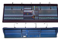
1
Heritage Series
Heritage 4000
Heritage 3000
Heritage 2000
Heritage Extender
Heritage 1000
Heritage 4000
The Midas Heritage 4000 is an evolution of the award winning
Heritage 3000 with an additional 16 more busses, which has
resulted in what many would regard as the ultimate stage
monitor console.
As monitor applications have become more demanding,
specifically with the increased usage of in-ear systems, it is now
common to see multiple consoles bussed together, in order to
achieve the required amount of outputs. The Heritage 4000
allows an engineer to run up to 40 mixes (plus stereo masters)
from a single console, benefiting from the world-renown
Heritage buss flexibility, and “road proven” digital assistance.
As with all Heritage, Legend and Siena consoles the Heritage
4000 can be linked via the Solo Tracking System to the Klark
Teknik Helix system allowing instant access to the EQ for any
input or output simply by pressing the solo key on the desk.
A beautifully elegant solution.
Key Features:
Frames: 48, 56, and 64
EQ: 4 band fully-parametric with Bell shelf selection on
Hi and Lo filters
Direct Output: Front panel switchable and level control
SIS™ panning with IMAGE control
24 Mix Outputs: front panel configurable per application
8 Stereo Aux outputs, 10 VCAs, 10 Automute groups,
27 x 8 matrix
Automation: snapshot automation of VCA assignment, all
mutes, all input channel and VCA levels
STS - compatible
2
3
4
5
Heritage 4000
Heritage 4000
Mono Input Module
The Mono Input Module is a fully featured mic/line channel strip
incorporating the classic XL4 mic-pre and MIDAS 4-band
parametric equaliser with 24 adjustable, dual mode Group Mix
controls and eight additional stereo Aux Mixes. The 24
configurable Mix rotaries operate as bus assign on/off switches as
well as conventional Aux sends, controlling the signal levels sent
to the corresponding Aux buses. These 24 Mix buses may be
configured as Mono Aux, Stereo Aux or Post Pan Group,
selectable in pairs. In Stereo Aux mode, the lefthand control of
each pair functions as a pan control while the righthand control
adjusts the Aux level. The channel insert points may be switched
pre- or post-EQ.
Masters Module
Full Left / Centre / Right metering is provided as part of the
Masters Module along with a large Solo-in-Place switch. Direct
inputs may be summed into the left and right buses for console
linking, or other applications, and these may be switched pre or
post the master insert point. Each of the eight Matrix Master
controls has Left/Right/Sum source switching and the matrix
feeds may be switched pre or post the Master fader. This module
also includes the talkback controls, overall control of the master
stereo balance and single fader control over the stereo mix level.
The master mute buttons are integrated into the snapshot
automation system and there’s a VCA link to allow the mono
output level to track that of the stereo master fader.
Each mono channel features the MIDAS SIS™ spacial imaging
system for use with Left, Centre Right loudspeaker systems. When
SIS™ is active, the Image control modifies the action of the pan
control so as to adjust the amount of centre panned signals
which are fed equally to both left and right outputs as well as to
the centre. This can be particularly useful for distributing the load
of high energy, centre-panned sounds across all FOH loudspeaker
arrays. A constant power law ensures that the overall balance will
not change as the Image control is adjusted.
The 8 dedicated Stereo Aux Masters are on the ‘Pod’ above, along
with their Solo, Mute and balance controls. Located here are also
the Stereo Aux Output meters assignment buttons to VCAs 9 and
10, Insert, Talk and Buss Direct input.
Stereo Input Module
Like the Mono Input Module, the stereo is a comprehensive,
mic/line channel strip incorporating the classic MIDAS 4-band
equaliser and 24 adjustable, dual mode Group Mix controls that
operate as bus assign on/off switches and Aux sends. The input
gain and EQ control settings apply to both the left and right
signal paths. The Aux modes are similar to those provided on the
mono channel, though when configured to mono, the signal is
derived from a sum of the left and right channels. Like the mono
version, the channel insert points may be switched pre or post
EQ. Bargraph metering indicates the pre-fader peak input levels
while a Mono button connects the post-fader channel signals to
the Mono Master fader. Left and right pan controls are used for
setting the stereo positioning of the two channels and a Stereo
routing button connects the post-fader channel signals to the
stereo bus via the pan controls.
Input faders
The Input faders are linked to an intuitive, VCA level automation
system, which is mainly controlled from the centre section of the
console, though status buttons and indicators are located
adjacent to each fader. Each fader has an automation safe button
that removes it from automation control as well as a Fader Safe
button which removes the fader from any form of remote control.
The set switch is used to program the channel automute and
VCA assignment when creating subgroups. Status LEDs are used
to show the VCA ‘virtual’ fader level as well as to prompt the
operator when nulling the faders. The focus is on fast, intuitive
use in a live performance situation.
Group Module
The Group Module provides a highly flexible stereo Group master
control strip with one direct input per Group that can be mixed
with the existing bus signal. These direct inputs may be
employed as extra effects returns or for console bus linking.
Eight matrix level controls are provided per channel and ‘per
channel’ pre/post switching is provided to determine whether
the Group’s matrix outputs are derived pre or post the Group
fader. VCA switches are fitted to assign the audio subgroups to
VCA control via VCA masters 9 and 10.
Clear level metering monitors the signal levels from -36dB to
+21dB. The Group insert point may be switched so that the signal
sent to the matrix mixes is either pre or post the insert point. A
large, illuminated mute button may be used for manual channel
muting or may be controlled from the Automute snapshot
automation system.
Monitor Module
The Monitor Module includes peak metering of the left and right
monitor signals, a variable frequency test oscillator with a 1kHz
fixed tone switch, pink noise generation and a talkback mic input.
The talkback mic may be routed to an external XLR or to the
console’s internal talk system, in which case local outputs are
dimmed by 20dB. The signal generator section may be routed to
the console’s internal Talk to All and Talk Select busses and/or to
an external XLR connector. The Talk to All switch takes priority
over other output talk switches so that the signal generator
section or mic can be routed to all outputs.
A headphone monitoring section is also fitted along with phase
reverse, left/right reverse switching mute and solo buttons for the
monitor output. A single fader provides overall control over all
three local monitor outputs and a switchable Solo Add mode
allows multiple channels to access to the Solo bus.
Matrix Module
Each Matrix Module provides full fader control and level metering
for four matrix outputs. Matrix outputs may be individually
assigned to VCA control from the master fader and Talk buttons
may be used to include the matrix outputs in the talkback
system. Safe buttons remove the matrix output from snapshot
automation control and Solo switches send the matrix signals to
the PFL mono and AFL buses.
VCA Master Faders
The VCA Master Faders are equipped with Solo and Mute buttons,
plus an Auto Safe switch that disables snapshot automation
control of both the VCA master faders and VCA mutes. If the Solo
button is pressed momentarily, it will latch on whereas if it is
pressed and held for more than one second, the latching is
disabled. The same status LED system is employed as on the
channel faders to show the VCA ‘virtual’ fader settings and to
assist the user in nulling the faders when necessary. The status
LEDs turn off when the console is in VCA or mute assignment
modes.
Automation System
The Heritage 4000 includes a highly sophisticated yet intuitive
Mute and VCA automation system designed specifically for live
performance. Numerical readouts of Act and Scene numbers is
provided and there’s direct Fast Key access to the ten most
commonly used snapshots as set up by the user. Snapshots may
be stored as either acts or scenes where scenes are organised as
sub-sets of acts. Scene recall may be achieved by stepping
through the stored scenes in numerical order using the Last/Next
buttons, by using the Act/Scene Up/Down buttons or by direct
recall using a Fast Key. Alternatively, scenes may be recalled
directly via MIDI. A check mode is provided so that virtual fader
positions for a newly recalled scene can be viewed before making
that scene active.
The automation data is read from two micro cards. A switch is
used to select whether card A or B is active. Potential fault
situations are also monitored by the status LEDs. Comprehensive
automation and MIDI editing is provided, though this may be
disabled during performance if required for security reasons.
The fader automation operates in either Real Fader mode or
Virtual Fader mode. In Real Fader mode the signal levels are
controlled by the physical faders, while in Virtual mode they are
controlled by the VCA automation system. In virtual mode, the 11
status LEDs adjacent to the faders show the VCA gain setting
regardless of the physical fader position.
In Real Fader mode, the automation system can still provide
visual prompts via the status LEDs. Comprehensive editing
facilities are provided, including the ability to edit, insert or copy
scenes.
Virtual Fader Recall mode generates a VCA fader level based on
the value at the time the last snapshot was stored. This level is
added to the physical fader level (effectively a ‘relative’ mode) and
the virtual fader level is displayed as a vertical bar of status LEDs.
6
7
Heritage 4000 Overview and Statistics
Heritage 4000 Specifications
Console Statistics
Input Impedance
The Heritage 4000 (48 channel frame, 44 mono 4 stereo) is a
46 buss console with an additional 27 x 8 output matrix.
The busses are:
8 stereo Aux = 16
24 stereo or mono configurable groups =24
1 stereo master =2
1 mono master=1
1 stereo AFL=2
1 mono PFL=1
TOTAL= 46
10 automute sub groups and 10 VCA sub groups which
include VCA sub group muting.
52 input channels plus an additional 42 direct inputs on the
group, stereo Aux and master modules.
A total XLR input count of 112 are:
52 channel mic inputs
24 group direct inputs
16 stereo Aux direct inputs
8 matrix bus inject inputs
3 solo bus inject inputs
2 master direct inputs
2 external inputs (2 track return)
1 master bus inject
1 talk mic input
1 talk external input
1 test bus input
A total of 212 balanced 1/4 inch jacks for inserts. These are:
52 input channel insert sends
52 input channel insert returns
24 audio group insert sends
24 audio group insert returns
16 stereo Aux insert sends
16 stereo Aux insert returns
8 matrix insert sends
8 matrix insert returns
3 master insert sends
3 master insert returns
3 local insert returns
Mic
Line
2k Balanced
20k Balanced
Equaliser
Hi pass slope
Mic
Hi pass frequency
continuously variable
- 3dB point
Treble Gain
continuously variable
+ 15 dB to -15 dB
centre detent = 0dB
Line Level Inputs
continuously
variable from
+ 15dB to + 60dB
continuously
variable from
-0dB to + 35dB
0dB
Treble Shelving Freq
Mic
Mic + Pad
Line Level Inputs
+ 6dBu
+ 31dBu
+ 21dBu
continuously variable
- 3dB point from 1k to 20k
Treble Bell Freq
continuously variable
centre from 1k to 20k
Mic (gain + 40dB)
Mic + Pad (gain 0dB)
Typ 115dB
Typ 80dB
Treble Bell Bandwidth
Mic (gain + 40dB)
Mic + Pad (gain 0dB)
Line
>100dB
>60dB
>50dB
continuously variable
0.1Oct. to 2Oct.
centre detent = 0.5Oct.
Hi Mid Gain
Frequency
Response
(20 to 20kHz)
Mic to Mix
(gain + 60dB)
+ 0dB to - 1dB
continuously variable
+ 15dB to -15dB
centre detent = 0dB
Hi Mid Freq
continuously variable
centre from 400Hz to 8k
Noise
(20 to 20kHz)
Mic EIN ref.150 Ω
(gain + 60dB)
-128dBu
Hi Mid Bandwidth
System Noise
(20 to 20kHz)
Summing Noise
(48 channels routed
with faders down)
Line to Mix Noise
(48 channels routed
at 0dB, pan centre)
- 80dB
continuously variable
0.1 Oct. to 2Oct.
centre detent = 0.5Oct.
Lo Mid Gain
continuously variable
+15 dB to -15 dB
centre detent = 0dB
Lo Mid Freq
continuously variable
centre from 100Hz to 2k
Lo Mid Bandwidth
continuously variable
0.1Oct. to 2Oct
centre detent = 0.5Oct.
Bass Gain
continuously variable
+ 15dB to - 15dB
centre detent = 0dB
Bass Shelving Freq
continuously variable
- 3dB point from 20Hz to 400Hz
Bass Bell Freq
continuously variable
centre from 20Hz to 400Hz
Bass Bell Bandwidth
continuously variable
0.1Oct. to 2Oct
centre detent = 0.5Oct.
Input Gain
Mic + Pad
Maximum
Input Level
58 long throw faders for mix control with fader position
recall and virtual fader functions.
CMR at 100kHz
1051 automated switch functions. These are:
480 input channel VCA sub group virtual assign switches
480 input channel mute sub group virtual assign switches
48 input channel mute switches
24 audio sub group mute switches
8 stereo Aux mute switches
8 matrix mute switches
3 master mute switches
CMR at 1kHz
A total of 105 peak program meters with 20 LED segments
on all outputs and 11 LED segments on input channels.
A total XLR output count of 105 These are:
44 input channel direct outputs
24 audio group outputs
16 stereo Aux outputs
8 matrix outputs
3 master outputs
3 solo outputs
6 local outputs
1 talk external output
Distortion at 1kHz Mic to Mix
(+ 60dB gain,
0dBu output)
<0.03%
Crosstalk at 1kHz
<-90dB
<-90dB
<-90dB
> 80dB
Weights and Dimensions
64 channel 60 mono/4 stereo
Dim A = 2815mm/110.82” Dim B = 2272mm/109.13”
338kg /745.2lbs
56 channel 52 mono/4 stereo
Dim A = 2559mm/100.74” Dim B = 2516mm/99.05”
313kg /690.1lbs
Weights are approximate and out of flight case
8
363mm/14.29”
189mm/7.44”
DIM B
DIM A
12˚
Channel to Channel
Mix to Mix
Channel to Mix
Maximum Fader
attenuation
Output Impedance All Line Outputs
599mm/23.58”
48 channel - 44 mono/4 stereo
Dim A = 2268mm/89.29” Dim B = 2225mm/87.59”
275kg /606.3lbs
-75dB
Headphones
50Ω
balanced source
to drive > 600Ω
To drive > 8Ω
Maximum
Output Level
All Line Outputs
Headphones
+ 21dBu
+ 21dBu
Nominal
Signal Level
Mic
-60dBu to
+10dBu
0dBu
+ 10dBu
Line
Headphones
12dB / Oct
1054mm/41.49”
9
TALK input
0
Block Diagrams
+25
+35
60
T RANSFORMER
BALANCING
OPTION
48V
MIC/LINE
INPUT
+15
O
+60
SIS
inser t
pre eq
PRE
20 freq 400
SEND
-
RETURN
-
MONO
SUM
0
VCA
+
_
MONO BUS
?
l
ST
MONO
stereo
+10
lcr
pre fade
SOLO
BUS LEFT
image
EQ
LEFT SOLO BUS
width
6 0.3
6
+/-
bass
15
60
160
20
400
freq
width
6 0.3
1 6
0.1
15
METERS
PRE
2
lo-mid
300
15
+/-
width
width
6 0.3
1 6
0.1
15
0.1
2
15
15
hi-mid
800
1k
3k
bell 100 freq 2k
400
freq8k
+/-
6 0.3
16
2
treble
3k
15
+/-
+6
PRE
C
(ONLY 2 OF 24
SHOWN FOR
CLARIT Y )
MIX BUS 2
0
bell
l
INSERT POINT
-20dB L/R REVERSE
4
5
2
3
3
4
4
?
2
5
3
safe
vca
4
5
5
6
6
MUTE
SAFE
safe
mute
INTERNAL
PRE/POST
OPTIONS
+10
HEADPHONES
phones
+10
+
SOLO BUS
O/P LEFT
+
-
direct o/p
MASTER
BUS RIGHT
EXT
EXTERNAL
INPUT
LEFT
SIGNAL PATH K EY
= ANALOGUE SIGNALS
SOLO TO
MASTERS
LEFT
+10
level
talk
mic
0
1kHz
+
talk
talk
internal external
signal
generator
PINK
SOLO TO
MASTERS
RIGHT
0
+
PFL BUS
O/P
generator generator
internal external
+10
PINK NOISE
level
-
EXTERNAL
INPUT
RIGHT
=D.C. SIGNALS
=AUT OMATION SIGNALS
7
SOLO BUS
O/P RIGHT
-
+10
level
OSCILLAT OR
+
TALK
EXTERNAL
O/P
-
5
6
TALK
solo
6
8
7
9
8
10
2
0
TALK
MIC
+21+
+18+
+15+
+12+
+9+
+6+
+3+
0
-3-6-9-12-15-18-21-24-27-30-33-36-
MASTER
BUS LEFT
DIRECT
VCA
VOLTAGE
7
7
8
8
9
9
SOLO
CONTROL
SCENE PREVIEW
3
SET LEDS MAY
FUNCTION IN
ANY ONE OFTHREE
WAYS AS SHOWN.
FUNCTION IS
DEPENDANT ON
ASSIGN MASTER
SWIT CHES.
0
+6
5
0
R T O BOTH
0
PRE
set
1
SOLO O/P
RIGHT 'B'
-3dB
T RANSFORMER
BALANCING
OPTION
set
1
-
MONO
r
LOGIC 2
set
1
SOLO O/P
RIGHT ‘ A'
VCA
MUTE
ST
2
+
RETURN
+10
LOGIC 1
set
1
MUTE
+
_
MONIT OR
FADER
PUSH ON
?
NOISE
REFERENCE
SOLO O/P
LEFT 'B'
(HALF NORMALISE D)
SEND
+
_
PFL INJECT
-
R
ON
PAD
SOLO O/P
LEFT ‘A'
VCA
RETURN
-
-3dB
MIX BUS 1
2
8k
1k freq 20k
SEND
+
+
_
INSERT POINT
-
PFL BUS
0
1
0.1
15
C/O
MUTE
+
-
+
_
SOLO
INJECT RIGHT
RIGHT SOLO BUS
PRE
MONO O/P
LEFT 'B'
A/B
SPEAKERS
(HALF NORMALISE D)
+
PUSH ON
0
0
-
RETURN
L
MONO
MONO O/P
LEFT ‘A'
VCA
MONO L T O BOTH
O
SOLO to stereo
SOLO
BUS RIGHT
PFL BUS
0
SOLO
+
_
SOLO
INJECT LEFT
FOUR BAND FULLY PARAMETRIC EQUALISER
SEND
REVERSE
PHASE
level
RIGHT BUS
pan r
+18
+15
+12
+9
+6
+3
0
-3
-6
-9
-25
0
-
COMMS
LEVEL
+
+
_
INSERT POINT
LEFT BUS
C
C/O
MUTE
+
mute
INS
INSERT POINT
+
TEST
INPUT
(SERVICE
USE ONLY )
A/B
SPEAKERS
(HALF NORMALISE D)
SOLO to mono
+10
160
gain
PAD
MONO masters
level
PHASE
REVERSE
PHANT OM
+
_
TALK
EXTERNAL
HI-PASS
FILTER
GAIN
9
safe
automation
10
10
VCA
FADER
10
MUTE GROUP POSITION
INDICATION
GROUP
TALK ALL
PRE
HERITAGE 4000 MONI
T OR MODULE
BLOCK DIAGRAM
HERITAGE 4000 INPUT MODULE
BLOCK DIAGRAM
+V
TALK
SELECTED
meter
change
over
GLOBAL
METERING
PRE
SOLO add mode
SOLO
LOGIC
SOLO CLEAR
solo clear
CAN BUS
H4000 INPUT FADER MODULE BLOCK DIAGRAM
l
HERITAGE 4000MASTER MODULE
BLOCK DIAGRAM
0
MUTE
insert
PRE
r
+21+
+18+
+15+
+12+
+9+
+6+
+3+
0
-3-6-9-12-15-18-21-24-27-30-33-36-
level
0
left
sum
right
T O MATRIX
2- 8
oo
MATRIX BUS
(1 OF 8)
PRE fader
PRE inser t
MASTERS
SUM RIGHT ’
MASTERS
SUM LEFT
MONO
VCA O/P
TALK
INST
MUTE
+10
l
MUTE
RETURN
output level
r
balance
+
_
INSERT POINT
SEND
MONO
BUS
ST
+
_
-
RETURN
SAFE
to mono
VCA link to
mono
direct input
SOLO LEFT
SOLO RIGHT
PFL
SOLO LOGIC
LEFT
DIRECT
-3dB
PRE
inser t
MUTE
0
+
_
+10dB
MUTE
+10
LEFT
BUS
MUTE
insert
PRE
INSERT POINT
-
+10
l
level
SEND
RETURN
MUTE
output level
r
MASTER
VCA O/P
INST
MUTE
INSERT POINT
PRE
inser t
MUTE
0
+
_
+10dB
+10
level
SOLO
SAFE
RETURN
+
direct input
balance
TALK
MASTER
O/P LEFT
VCA
+
_
TALK
l
r
balance
RIGHT
BUS
RIGHT
DIRECT
TALK
SEND
NOISE
BUS
INST
INSERT POINT
+
INST
+
level
SOLO
0
MASTER
O/P MONO
VCA
SOLO
SOLO
+
mono c
( entre)
+
MONO
INJECT
MASTERS
SUM MONO
0
TALK ALL
INSERT POINT
SEND
MATRIX SEND
(1 OF 8)
+10
mono
METERS PRE
TALK
SELECTED
INST
+10
m-c
+21+
+18+
+15+
+12+
+9+
+6+
+3+
0
-3-6-9-12-15-18-21-24-27-30-33-36-
SOLO
TALK
+
_
+
VCA
-
SEND
MASTER
O/P RIGHT
RETURN
SAFE
s
o
l
o
i
n
p
l
a
c
e
AUT OMATION
SIP O/P
SOLO LOGIC
SOLO LEFT
SOLO RIGHT
PFL
PREVIEW
MUTE
AUT OMATION
HERITAGE 4000 STEREOAUX
MODULE BLOCK DIAGRAM
l
METERS PRE
TALK
SELECTED
TALK ALL
MATRIX 1
INJECT
r
l
+21+
+18+
+15+
+12+
+9+
+6+
+3+
0
-3-6-9-12-15-18-21-24-27-30-33-36-
HERITAGE 4000MATRIX MODULE
BLOCK DIAGRAM
r
+21+
+18+
+15+
+12+
+9+
+6+
+3+
0
-3-6-9-12-15-18-21-24-27-30-33-36-
+
_
INSERT POINT
SEND
MATRIX
REFERENCE
BUS
+
INST
+
MATRIX1
BUS
SAFE
RETURN
MUTE
solo
TALK
INST
+
MATRIX 2
BUS
MATRIX 2
INJECT
MATRIX 1
OUTPUT
VCA
+
_
INSERT POINT
-
+
_
SEND
TALK
+
+
_
VCA
RETURN
SAFE
solo
MATRIX 2
OUTPUT
-
MUTE
SOLO
split
PREVIEW
SOLO LEFT
MUTE
AUT OMATION
SOLO RIGHT
10
PFL
5
0
MASTERS VCA
MATRIX 5
INJECT
VCA
VCA
SOLO LOGIC
5
10
FROM MASTERS
SOLO
split
+
_
INSERT POINT
SEND
MATRIX
REFERENCE
BUS
+
INST
+
MATRIX 5
BUS
VCA
+
_
SAFE
RETURN
solo
TALK
INST
+
MATRIX 6
BUS
MATRIX 6
INJECT
MATRIX 5
OUTPUT
MUTE
INSERT POINT
-
+
_
SEND
TALK
+
_
VCA
solo
+
-
RETURN
SAFE
MATRIX 6
OUTPUT
MUTE
10
5
0
VCA
10
VCA
FROM MASTERS
5
10
11
Heritage 3000
The Heritage 3000 has established itself as the international
industry standard in concert sound for Front of House and
monitor applications. Defined not only by its striking colour but
also by all those things that make it so unmistakably Midas, the
Heritage 3000 has proved to be a runaway success from day one.
Firstly, it's flexible - at home in a theatre, an outside broadcast
truck, on stage or at front of house, the H3000 offers a unique,
easy to use, three position switching system that changes the
consoles output functions according to the application.
Secondly it has all of the hallmarks which make it sound so
distinctly Midas. They include a new mic amplifier which
further improves on the XL4 design giving a CMR improvement
of +30dB whilst retaining the XL4's constant HF bandwidth
topology, assuring excellent amplifier stability, RF rejection and
noise performance at all gains, plus the legendary fully
parametric XL4 EQ. This powerful desk is available in frame
sizes from 24 to 64 inputs and is as tough as they come. With
it's contemporary styling and vast range of features plus the
Midas assurance of quality, it is little wonder this desk is the
darling of the rental market.
Key Features:
Frames: 16 Extender, 24, 32, 40, 48, 56, and 64
(please note the 16 extender cannot be used with consoles
greater than 48 channel)
EQ: 4 band fully-parametric
Direct Output: front panel switchable and level control
SIS™ panning with IMAGE control
24 Mix Outputs: front panel configurable per application
10 VCAs, 10 Automute groups, 27 x 8 matrix
Automation: snapshot automation of VCA routing, mutes, all
channel and VCA levels
STS - compatible
12
13
14
15
Heritage 3000
Heritage 3000
Mono Input Module
The Mono Input Module is a fully featured mic/line channel strip
incorporating the classic XL4 mic-pre and MIDAS 4-band
parametric equaliser with 24 adjustable, dual mode Group Mix
controls. The 24 configurable Mix rotaries operate as bus assign
on/off switches as well as conventional Aux sends, controlling the
signal levels sent to the corresponding Aux buses. These 24 Mix
buses may be configured as Mono Aux, Stereo Aux or Post Pan
Group, selectable in pairs. In Stereo Aux mode, the lefthand
control of each pair functions as a pan control while the
righthand control adjusts the Aux level. The channel insert points
may be switched pre- or post-EQ.
Masters Module
Full Left / Centre / Right metering is provided as part of the
Masters Module along with a large Solo-in-Place switch. Direct
inputs may be summed into the left and right buses for console
linking, or other applications, and these may be switched pre or
post the master insert point. Each of the eight Matrix Master
controls has Left/Right/Sum source switching and the matrix
feeds may be switched pre or post the Master fader. This module
also includes the talkback controls, overall control of the master
stereo balance and single fader control over the stereo mix level.
The master mute buttons are integrated into the snapshot
automation system and there’s a VCA link to allow the mono
output level to track that of the stereo master fader.
Each mono channel features the MIDAS SIS™ spacial imaging
system for use with Left, Centre Right loudspeaker systems. When
SIS™ is active, the Image control modifies the action of the pan
control so as to adjust the amount of centre panned signals
which are fed equally to both left and right outputs as well as to
the centre. This can be particularly useful for distributing the load
of high energy, centre-panned sounds across all FOH loudspeaker
arrays. A constant power law ensures that the overall balance will
not change as the Image control is adjusted.
Stereo Input Module
Like the Mono Input Module, the stereo is a comprehensive,
mic/line channel strip incorporating the classic MIDAS 4-band
equaliser and 24 adjustable, dual mode Group Mix controls that
operate as bus assign on/off switches and Aux sends. The input
gain and EQ control settings apply to both the left and right
signal paths. The Aux modes are similar to those provided on the
mono channel, though when configured to mono, the signal is
derived from a sum of the left and right channels. Like the mono
version, the channel insert points may be switched pre or post
EQ. Bargraph metering indicates the pre-fader peak input levels
while a Mono button connects the post-fader channel signals to
the Mono Master fader. Left and right pan controls are used for
setting the stereo positioning of the two channels and a Stereo
routing button connects the post-fader channel signals to the
stereo bus via the pan controls.
Input faders
The Input faders are linked to an intuitive, VCA level automation
system, which is mainly controlled from the centre section of the
console, though key status buttons and indicators are located
adjacent to each fader. Each fader has a Automation Safe button
that removes it from automation control as well as a Fader Safe
button which removes the fader from any form of remote control.
The set switch is used to program the channel automute and
VCA assignment when creating subgroups. Status LEDs are used
to show the VCA ‘virtual’ fader level as well as to prompt the
operator when nulling the faders. The focus is on fast, intuitive
use in a live performance situation.
Group Module
The Group Module provides a highly flexible stereo Group master
control strip with one direct input per Group that can be mixed
with the existing bus signal. These direct inputs may be
employed as extra effects returns or for console bus linking. Eight
matrix level controls are provided per channel and ‘per channel’
pre/post switching is provided to determine whether the Group’s
matrix outputs are derived pre or post the Group fader. VCA
switches are fitted to assign the audio subgroups to VCA control
via VCA masters 9 and 10.
Clear level metering monitors the signal levels from -36dB to
+21dB. The Group insert point may be switched so that the signal
sent to the matrix mixes is either pre or post the insert point. A
large, illuminated mute button may be used for manual channel
muting or may be controlled from the Automute snapshot
automation system.
Monitor Module
The Monitor Module includes peak metering of the left and right
monitor signals, a variable frequency test oscillator with a 1kHz
fixed tone switch, pink noise generation and a talkback mic input.
The talkback mic may be routed to an external XLR or to the
console’s internal talk system, in which case local outputs are
dimmed by 20dB. The signal generator section may be routed to
the console’s internal Talk to All and Talk Select busses and/or to
an external XLR connector. The Talk to All switch takes priority
over other output talk switches so that the signal generator
section or mic can be routed to all outputs.
A headphone monitoring section is also fitted along with phase
reverse, left/right reverse switching mute and solo buttons for the
monitor output. A single fader provides overall control over all
three local monitor outputs and a switchable Solo Add mode
allows multiple channels to access to the Solo bus.
Matrix Module
Each Matrix Module provides full fader control and level metering
for four matrix outputs. Matrix outputs may be individually
assigned to VCA control from the master fader and Talk buttons
may be used to include the matrix outputs in the talkback
system. Safe buttons remove the matrix output from snapshot
automation control and Solo switches send the matrix signals to
the PFL mono and AFL buses.
VCA Master Faders
The VCA Master Faders are equipped with Solo and Mute buttons,
plus an Auto Safe switch that disables snapshot automation
control of both the VCA master faders and VCA mutes. If the Solo
button is pressed momentarily, it will latch on whereas if it is
pressed and held for more than one second, the latching is
disabled. The same status LED system is employed as on the
channel faders to show the VCA ‘virtual’ fader settings and to
assist the user in nulling the faders when necessary. The status
LEDs turn off when the console is in VCA or mute assignment
modes.
Automation System
The Heritage 3000 includes a highly sophisticated yet intuitive
Mute and VCA automation system designed specifically for live
performance. Numerical readouts of Act and Scene numbers is
provided and there’s direct Fast Key access to the ten most
commonly used snapshots as set up by the user. Snapshots may
be stored as either acts or scenes where scenes are organised as
sub-sets of acts. Scene recall may be achieved by stepping
through the stored scenes in numerical order using the Last/Next
buttons, by using the Act/Scene Up/Down buttons or by direct
recall using a Fast Key. Alternatively, scenes may be recalled
directly via MIDI. A check mode is provided so that virtual fader
positions for a newly recalled scene can be viewed before making
that scene active.
The automation data is read from two micro cards. A switch is
used to select whether card A or B is active. Potential fault
situations are also monitored by the status LEDs. Comprehensive
automation and MIDI editing is provided, though this may be
disabled during performance if required for security reasons.
The fader automation operates in either Real Fader mode or
Virtual Fader mode. In Real Fader mode the signal levels are
controlled by the physical faders, while in Virtual mode they are
controlled by the VCA automation system. In virtual mode, the 11
status LEDs adjacent to the faders show the VCA gain setting
regardless of the physical fader position.
In Real Fader mode, the automation system can still provide
visual prompts via the status LEDs. Comprehensive editing
facilities are provided, including the ability to edit, insert or copy
scenes.
Virtual Fader Recall mode generates a VCA fader level based on
the value at the time the last snapshot was stored. This level is
added to the physical fader level (effectively a ‘relative’ mode) and
the virtual fader level is displayed as a vertical bar of status LEDs.
16
17
Heritage 3000 Overview and Statistics
Heritage 3000 Specifications
Console Statistics
Input Impedance
The Heritage 3000 is a 30 buss console with an additional 27
x 8 output matrix. The busses are:
24 stereo or mono configurable groups = 24
1 stereo master = 2
1 mono master = 1
1 stereo AFL = 2
1 mono PFL = 1
TOTAL = 30
10 automute sub groups and 10 VCA sub groups which
include VCA sub group muting.
52 input channels plus an additional 26 direct inputs on the
group and master modules.
A total of 180 balanced 1/4 inch jacks for inserts are:
52 input channel insert sends
52 input channel insert returns
24 audio group insert sends
24 audio group insert returns
8 matrix insert sends
8 matrix insert returns
3 master insert sends
3 master insert returns
3 local insert returns
Mic
Hi pass frequency
continuously variable
- 3dB point
Treble Gain
continuously variable
+ 15dB to -15dB
centre detent = 0dB
Line Level Inputs
continuously
variable from
+ 15dB to + 60dB
continuously
variable from
-0dB to + 35dB
0dB
Treble Shelving Freq
Mic
Mic + Pad
Line Level Inputs
+ 6dBu
+ 31dBu
+ 21dBu
continuously variable
- 3dB point from 1k to 20k
Treble Bell Freq
continuously variable
centre from 1k to 20k
Mic (gain + 40dB)
Mic + Pad (gain 0dB)
Typ 115dB
Typ 80dB
Treble Bell Bandwidth
Mic (gain + 40dB)
Mic + Pad (gain 0dB)
Line
>100dB
>60dB
>50dB
continuously variable
0.1Oct. to 2Oct.
centre detent = 0.5Oct.
Hi Mid Gain
Frequency
Response
(20 to 20kHz)
Mic to Mix
(gain + 60dB)
+ 0dB to - 1dB
continuously variable
+ 15dB to -15dB
centre detent = 0dB
Hi Mid Freq
continuously variable
centre from 400Hz to 8k
Noise
(20 to 20kHz)
Mic EIN ref.150 Ω
(gain + 60dB)
-128dBu
Hi Mid Bandwidth
System Noise
(20 to 20kHz)
Summing Noise
(48 channels routed
with faders down)
Line to Mix Noise
(48 channels routed
at 0dB, pan centre)
- 80dB
continuously variable
0.1Oct. to 2Oct.
centre detent = 0.5Oct.
Lo Mid Gain
continuously variable
+15dB to -15dB
centre detent = 0dB
Lo Mid Freq
continuously variable
centre from 100Hz to 2k
Lo Mid Bandwidth
continuously variable
0.1Oct. to 2Oct
centre detent = 0.5Oct.
Bass Gain
continuously variable
+ 15dB to - 15dB
centre detent = 0dB
Bass Shelving Freq
continuously variable
- 3dB point from 20Hz to 400Hz
Bass Bell Freq
continuously variable
centre from 20Hz to 400Hz
Bass Bell Bandwidth
continuously variable
0.1Oct. to 2Oct
centre detent = 0.5Oct.
Maximum
Input Level
58 long throw faders for mix control with fader position
recall and virtual fader functions.
CMR at 100kHz
CMR at 1kHz
A total XLR output count of 89 are:
44 input channel direct outputs
24 audio group outputs
8 matrix outputs
3 master outputs
3 solo outputs
6 local outputs
1 talk external output
Weights and Dimensions
48 channel - 44 mono/4 stereo (Bob Tail Frame)
Dim A = 2138mm/84.17” Dim B = N/A
205kg /451.94lbs
32 channel - 28 mono/4 stereo
Dim A = 1756mm/69.13” Dim B = 1713mm/67.44”
165kg /363.8lbs
56 channel - 52 mono/4 stereo
Dim A = 2559mm/100.74” Dim B = 2516mm/99.05”
253kg /564.4lbs
40 channel - 36 mono/4 stereo
Dim A = 2012mm/79.21” Dim B = 1969mm/77.52”
188kg /414.5lbs
64 channel - 60 mono/4 stereo
Dim A = 2815mm/110.82” Dim B = 2772mm/109.13”
260kg /573.2lbs
48 channel - 44 mono/4 stereo
Dim A = 2268mm/89.29” Dim B = 2225mm/87.59”
215kg /473.9lbs
Weights are approximate and out of flight case
12˚
-75dB
Distortion at 1kHz Mic to Mix
(+ 60dB gain,
0dBu output)
<0.03%
Crosstalk at 1kHz
<-90dB
<-90dB
<-90dB
> 80dB
Channel to Channel
Mix to Mix
Channel to Mix
Maximum Fader
attenuation
Output Impedance All Line Outputs
363mm/14.29”
24 channel - 20 mono/4 stereo
Dim A = 1484mm/58.42” Dim B = 1441mm/56.73”
140kg /308.6lbs
189mm/7.44”
18
Equaliser
Hi pass slope
Mic + Pad
A total of 89 peak program meters with 20 LED segments on
all outputs and 11 LED segments on input channels.
DIM B
DIM A
2k Balanced
20k Balanced
Input Gain
1043 automated switch functions are:
480 input channel VCA sub group virtual assign switches
480 input channel mute sub group virtual assign switches
48 input channel mute switches
24 audio sub group mute switches
8 matrix mute switches
3 master mute switches
A total XLR input count of 95 are:
52 channel mic inputs
24 group direct inputs
8 matrix bus inject inputs
3 solo bus inject inputs
2 master direct inputs
2 external inputs (2 track return)
1 master bus inject
1 talk mic input
1 talk external input
1 test bus input
Mic
Line
Headphones
50 Ω
balanced source
to drive > 600Ω
To drive > 8Ω
Maximum
Output Level
All Line Outputs
Headphones
+ 21dBu
+ 21dBu
Nominal
Signal Level
Mic
-60dBu to
+10dBu
0dBu
+ 10dBu
Line
Headphones
12dB / Oct
1054mm/41.49”
19
Block Diagrams
20
21
Heritage 2000
The Heritage 2000 offers all the superb audio performance and
automation features of the Heritage 3000 in a package that is
entirely dedicated to FOH duties.
It is suitable for a variety of applications from rock and roll to
theatre to large-scale conferences and conventions and of
course OB vehicles. As with all consoles in the Heritage range,
the Heritage 2000 sports the Midas Heritage mic preamp,
which is of the highest quality yet produced by Midas, as well
as the EQ section. Sophisticated automation via the on-board
computer enables the console to memorise all of the input
fader positions to be recalled at a later date, and also
memorises the mute status of the board.
Another feature shared with the Heritage 3000 is the Stereo
Imaging System (SIS™) with true LCR panning and an image
width control device that is unique to the Heritage Series.
For applications where large numbers of Aux sends are not
required, the Heritage 2000 enables customers to benefit from
the technology, legacy and quality of the 3000, with the
advantage of a dedicated FOH control surface.
Key Features:
Frames: 16 Extender, 24, 32, 40, 48, 56, and 64
(please note the 16 extender cannot be used with consoles
greater than 48 channel)
EQ: 4 band fully-parametric
Direct Output: Front panel switchable and level control
SIS™ panning with IMAGE control
12 Aux Sends, 12 Audio Sub Groups, 10 VCAs, 10
automute groups 15 x 8 matrix
Automation: snapshot automation of VCA routing, mutes, all
channel and VCA levels
STS - compatible
22
23
24
25
Heritage 2000
Heritage 2000
Mono Input Module
The Mono Input Module is a fully featured mic/line channel strip
incorporating a classic MIDAS 4-band equaliser that features two
fully parametric mid sections, variable frequency high and low
filters with switchable shelving/bell characteristics and a variable
frequency 20 Hz to 400 Hz high-pass filter. Input pad, phase and
phantom power switches are fitted.
Masters Module
Full Left / Centre / Right metering is provided as part of the
Masters Module along with a large Solo-in-Place switch. Direct
inputs may be summed into the left and right buses for console
linking, or other applications, and these may be switched pre or
post the master insert point. Each of the eight Matrix Master
controls has Left/Right/Sum source switching and the matrix
feeds may be switched pre or post the Master fader. This module
also includes the talkback controls, overall control of the master
stereo balance and single fader control over the stereo mix level.
The master mute buttons are integrated into the snapshot
automation system and there’s a VCA link to allow the mono
output level to track that of the stereo master fader.
Eight mono Aux controls may be individually assigned to pre or
post-fade operation with two further stereo Aux sends, with level
and pan controls, feeding Aux busses 9 - 10 and 11 - 12. A
variable gain, direct channel output is available and this may be
switched pre or post- equaliser. The channel insert points may
also be switched pre- or post-EQ and a switch is provided for
linking the insert send to the insert return, effectively bypassing
any connected device. Each mono channel features the MIDAS
SIS™ spacial imaging system for use with Left, Centre Right
loudspeaker systems. When SIS™ is active, the Image control
modifies the action of the pan control so as to feed centre
panned signals equally to both left and right outputs as well as to
the centre. This can be particularly useful for distributing the load
of high energy, centre-panned sounds across all FOH loudspeaker
arrays. A constant power law ensures that the overall balance will
not change as the Image control is adjusted.
Group routing for 12 busses is provided along with a Pan switch
that affects all group routing by moving the channel source from
post-fader to post- both the fader and the Pan control. Pre-fade
metering is provided close to the fader and a Mono switch allows
the post-fader channel signal to be routed to the mono master
buss. A large, illuminated mute button may be used for manual
channel muting or may be controlled from the Automute
snapshot automation system.
Stereo Input Module
Like the Mono Input Module, the stereo is a comprehensive,
mic/line channel strip and incorporates the classic MIDAS 4-band
equaliser. There are eight mono Aux sends and two stereo Aux
sends, all individually switchable pre or post-fader. The Aux and
insert modes are similar to those provided on the mono channel
where the stereo sends may be switched to mono, in which case
the signal is derived from a sum of the left and right channels.
Like the mono version, the channel insert points may be
switched pre or post EQ. The input sources are regulated using a
gain and a balance control with a separate phase switch for each
channel. Bargraph metering indicates the pre-fader peak input
levels for both channels while a Mono button connects the postfader channel signals to the Mono Master buss. Left and right pan
controls are used for setting the stereo positioning of the two
channels and a Stereo routing button connects the post-fader
channel signals to the stereo bus via the pan controls. Routing is
identical to the mono module. A large, illuminated mute button
may be used for manual channel muting or may be controlled
from the Automute snapshot automation system.
26
Input Fader
The Input faders are linked to an intuitive, VCA level automation
system, which is mainly controlled from the centre section of the
console, though key status buttons and indicators are located
adjacent to each fader. Each fader has a Automation Safe button
that removes it from automation control as well as a Fader Safe
button which removes the fader from any form of remote control.
The set switch is used to program the channel automute and
VCA assignment when creating subgroups. Status LEDs are used
to show the VCA ‘virtual’ fader level as well as to prompt the
operator when nulling the faders. The focus is on fast, intuitive
use in a live performance situation.
Group Module
The Group Module provides a highly flexible stereo Group master
control strip with one direct input per Group that can be mixed
with the existing bus signal. These direct inputs may be
employed as extra effects returns or for console bus linking. Eight
matrix level controls are provided per channel and ‘per channel’
pre/post switching is provided to determine whether the Group’s
matrix outputs are derived pre or post the Group fader. VCA
switches are fitted to assign the audio subgroups to VCA control
via VCA masters 9 and 10.
Clear level metering monitors the signal levels from -36dB to
+21dB. The Group insert point may be switched so that the signal
sent to the matrix mixes is either pre or post the insert point. A
large, illuminated mute button may be used for manual channel
muting or may be controlled from the Automute snapshot
automation system.
Aux Module
Each module provides four Aux output master control sections
complete with post-fade level metering. VCA switches assign the
Aux output to VCA control from VCA master 9 and 10 while a Safe
switch may be used to remove the Aux from the snapshot
automation system. Solo (PFL mono/AFL stereo) and mute
buttons are provided for each send and the mutes may be
controlled via the snapshot automation system. As a safety
feature, the Solo buttons are self-cancelling whenever a new
channel is solo’d - multiple channels can be solo’d using the Solo
Add Mode switch on the Monitor module. A Split button changes
the Aux AFL solos from mono to stereo.
Monitor Module
The Monitor Module includes peak metering of the left and right
monitor signals, a variable frequency test oscillator with a 1kHz
fixed tone switch, pink noise generation and a talkback mic input.
The talkback mic may be routed to an external XLR or to the
console’s internal talk system, in which case local outputs are
dimmed by 20dB. The signal generator section may be routed to
the console’s internal Talk to All and Talk Select busses and/or to
an external XLR connector. The Talk to All switch takes priority
over other output talk switches so that the signal generator
section or mic can be routed to all outputs.
A headphone monitoring section is also fitted along with phase
reverse, left/right reverse switching mute and solo buttons for the
monitor output. A single fader provides overall control over all
three local monitor outputs and a switchable Solo Add mode
allows multiple channels to access to the Solo bus.
Matrix Module
Each Matrix Module provides full fader control and level metering
for four matrix outputs. Matrix outputs may be individually
assigned to VCA control from the master fader and Talk buttons
may be used to include the matrix outputs in the talkback
system. Safe buttons remove the matrix output from snapshot
automation control and Solo switches send the matrix signals to
the PFL mono and AFL buses.
VCA Master Fader
The Heritage 2000 includes a highly sophisticated yet intuitive
VCA automation system designed specifically for live
performance. Numerical readouts of Act and Scene numbers are
provided and there’s direct Fast Key access to the ten most
commonly used snapshots as set up by the user. Snapshots may
be stored as either acts or scenes where scenes are organised as
sub-sets of acts. Scene recall may be achieved by stepping
through the stored scenes in numerical order using the Last/Next
buttons, by using the Act/Scene Up/Down buttons or by direct
recall using a Fast Key. Alternatively, scenes may be recalled
directly via MIDI. A check mode is provided so that virtual fader
positions for a newly recalled scene can be viewed before making
that scene active.
Automation
The automation data is read from a micro card (up to two may be
installed at any one time) and status LEDs show whether the
automation is active or inactive. Where two cards are installed, a
switch is used to select whether card A or B is active. Potential
fault situations are also monitored by the status LEDs.
Comprehensive automation and MIDI editing is provided, though
this may be disabled during performance if required for security
reasons.
The fader automation operates in either Real Fader mode or
Virtual Fader mode. In Real Fader mode, the signal levels are
controlled by the physical faders while in Virtual mode, they are
controlled by the VCA automation system. In virtual mode, the 11
meter LEDs adjacent to the faders show the VCA gain setting
regardless of the physical fader position.
In Real Fader mode, the automation system can still provide
visual prompts via the status LEDs. Comprehensive editing
facilities are provided, including the ability to edit, insert or copy
scenes.
27
Heritage 2000 Overview and Statistics
Heritage 2000 Specifications
Console Statistics
Input Impedance
10 automute sub groups and 10 VCA sub groups which
include VCA sub group muting.
A total of 180 balanced 1/4 inch jacks for inserts are:
52 input channel insert sends
52 input channel insert returns
12 audio group insert sends
12 audio group insert returns
12 Aux insert sends
12 Aux insert returns
8 matrix insert sends
8 matrix insert returns
3 master insert sends
3 master insert returns
3 local insert sends
3 local insert returns
52 input channels plus an additional 14 direct inputs on the
group and master modules.
58 long throw faders for mix control with fader position
recall and virtual fader functions.
A total XLR input count of 95 are:
52 channel mic inputs
12 group direct inputs
12 Aux bus injects
8 matrix bus inject inputs
3 solo bus inject inputs
2 master direct inputs
2 external inputs (2 track return)
1 master bus inject
1 talk mic input
1 talk external input
1 test bus input
1043 automated switch functions are:
480 input channel VCA sub group virtual assign switches
480 input channel mute sub group virtual assign switches
48 input channel mute switches
12 audio sub group mute switches
12 Aux mute switches
8 matrix mute switches
3 master mute switches
The Heritage 2000 is a 30 buss console with an additional 15
x 8 output matrix. The busses are:
12 audio groups = 24
8 mono Aux = 8
2 stereo Aux = 4
1 stereo master = 2
1 mono master = 1
1 stereo AFL = 2
1 mono PFL = 1
TOTAL = 30
64 channel - 60 mono/4 stereo
Dim A = 2815mm/110.82” Dim B = 2772mm/109.13”
245kg /540lbs
48 channel - 44 mono/4 stereo
Dim A = 2268mm/89.29” Dim B = 2225mm/87.59”
200kg /440.9lbs
Weights are approximate and out of flight case
DIM B
DIM A
28
12˚
Hi pass frequency
continuously variable
- 3dB point
Treble Gain
continuously variable
+ 15dB to -15dB
centre detent = 0dB
Line Level Inputs
continuously
variable from
+ 15dB to + 60dB
continuously
variable from
-0dB to + 35dB
0dB
Treble Shelving Freq
Mic
Mic + Pad
Line Level Inputs
+ 6dBu
+ 31dBu
+ 21dBu
continuously variable
- 3dB point from 1k to 20k
Treble Bell Freq
continuously variable
centre from 1k to 20k
Mic (gain + 40dB)
Mic + Pad (gain 0dB)
Typ 115dB
Typ 80dB
Treble Bell Bandwidth
Mic (gain + 40dB)
Mic + Pad (gain 0dB)
Line
>100dB
>60dB
>50dB
continuously variable
0.1Oct. to 2Oct.
centre detent = 0.5Oct.
Hi Mid Gain
Frequency
Response
(20 to 20kHz)
Mic to Mix
(gain + 60dB)
+ 0dB to - 1dB
continuously variable
+ 15dB to -15dB
centre detent = 0dB
Hi Mid Freq
continuously variable
centre from 400Hz to 8k
Noise
(20 to 20kHz)
Mic EIN ref.150 Ω
(gain + 60dB)
-128dBu
Hi Mid Bandwidth
System Noise
(20 to 20kHz)
Summing Noise
(48 channels routed
with faders down)
Line to Mix Noise
(48 channels routed
at 0dB, pan centre)
- 80dB
continuously variable
0.1Oct. to 2Oct.
centre detent = 0.5Oct.
Lo Mid Gain
continuously variable
+15dB to -15dB
centre detent = 0dB
Lo Mid Freq
continuously variable
centre from 100Hz to 2k
Lo Mid Bandwidth
continuously variable
0.1Oct. to 2Oct
centre detent = 0.5Oct.
Bass Gain
continuously variable
+ 15dB to - 15dB
centre detent = 0dB
Bass Shelving Freq
continuously variable
- 3dB point from 20Hz to 400Hz
Bass Bell Freq
continuously variable
centre from 20Hz to 400Hz
Bass Bell Bandwidth
continuously variable
0.1Oct. to 2Oct
centre detent = 0.5Oct.
CMR at 100kHz
CMR at 1kHz
-75dB
Distortion at 1kHz Mic to Mix
(+ 60dB gain,
0dBu output)
<0.03%
Crosstalk at 1kHz
<-90dB
<-90dB
<-90dB
> 80dB
Channel to Channel
Mix to Mix
Channel to Mix
Maximum Fader
attenuation
Output Impedance All Line Outputs
363mm/14.29”
40 channel - 36 mono/4 stereo
Dim A = 2012mm/79.21” Dim B = 1969mm/77.52”
173kg /381.4lbs
189mm/7.44”
56 channel - 52 mono/4 stereo
Dim A = 2559mm/100.74” Dim B = 2516mm/99.05”
231kg /509.3lbs
Mic
Maximum
Input Level
Weights and Dimensions
32 channel - 28 mono/4 stereo
Dim A = 1756mm/69.13” Dim B = 1713mm/67.44”
155kg /341.7lbs
Equaliser
Hi pass slope
Mic + Pad
A total XLR output count of 89 are:
44 input channel direct outputs
12 audio group outputs
12 Aux outputs
8 matrix outputs
3 master outputs
3 solo outputs
6 local outputs
1 talk external output
48 channel - 44 mono/4 stereo (Bob Tail Frame)
Dim A = 2138mm/84.17” Dim B = N/A
190kg /418.9lbs
2k Balanced
20k Balanced
Input Gain
A total of 89 peak program meters with 20 LED segments on
all outputs and 11 LED segments on input channels.
24 channel - 20 mono/4 stereo
Dim A = 1484mm/58.42” Dim B = 1441mm/56.73”
133kg /293.2lbs
Mic
Line
Headphones
50 Ω
balanced source
to drive > 600W
To drive > 8W
Maximum
Output Level
All Line Outputs
Headphones
+ 21dBu
+ 21dBu
Nominal
Signal Level
Mic
-60dBu to
+10dBu
0dBu
+ 10dBu
Line
Headphones
12dB / Oct
1054mm/41.49”
29
Block Diagrams
HI-PASS
FILTER
GAIN
+25
+35
60
PHASE
REVERSE
PHANT OM
T RANSFORMER
BALANCING
OPTION
48V
MIC/LINE
INPUT
+15
160
PRE
20 freq 400
SEND
-
-
LEFT BUS
C
VCA
+
RETURN
_
HERITAGE 2000
MASTER MODULE
BLOCK DIAGRAM
MONO BUS
?
l
RIGHT BUS
pan r
ST
stereo
MONO
lcr
image
EQ
TEST
INPUT
(SERVICE
USE ONLY )
+18
+15
+12
+9
+6
+3
0
-3
-6
-9
-25
PFL BUS
LEFT SOLO BUS
RIGHT SOLO BUS
PAN
FOUR BAND FULLY PARAMETRIC EQUALISER
0
0
6 0.3
6
width
6 0.3
1 6
bass
60
+/-
2
0.1
15
15
lo-mid
300
15
+/-
0.1
2
15
15
hi-mid
800
1k
3k
bell 100 freq 2k
400
freq8k
160
+/-
6 0.3
16
2
treble
3k
15
+/-
2
?
8k
+6
20
freq
400
1k freq 20k
aux
MONO
bell
pre
C
NOISE
REFERENCE
l
pan
r
+
_
INSERT POINT
SEND
4
5
1
2
0
3
3
4
4
5
3
5
5
7
6
+10dB
MUTE
SEND
9
INTERNAL
PRE/POST
OPTIONS
direct o/p
-
6
6
solo
8
8
9
9
9
10
10
VCA
FADER
10
MUTE GROUP POSITION
INDICATION
GROUP
+10dB
SEND
REVERSE
PHASE
PRE
fader
MASTER
BUS MONO
pan
SEND
PFL INJECT
r
pan
INSERT POINT
-
direct input
PRE
inser t
MUTE
0
+
_
+10dB
TALK
SEND
MASTER
BUS LEFT
MASTER
BUS RIGHT
solo
EXTERNAL
INPUT
LEFT
+
SAFE
RIGHT O/P
solo
SOLO O/P
RIGHT 'B'
5
+10
0
0
5
10
EXT
RETURN
5
MONIT OR
0
FADER
-
MUTE
+10
SOLO
level
MUTE
5
10
+10
HEADPHONES
phones
+10
+
+21+
+18+
+15+
+12+
+9+
+6+
+3+
0
-3-6-9-12-15-18-21-24-27-30-33-36-
SOLO BUS
O/P LEFT
-
TALK
MIC
SOLO TO
MASTERS
LEFT
+10
level
talk
mic
0
1kHz
+
talk
talk
internal external
PINK
signal
generator
SOLO TO
MASTERS
RIGHT
0
+
PINK NOISE
PFL BUS
O/P
generator generator
internal external
+10
level
-
EXTERNAL
INPUT
RIGHT
split
+
SOLO RIGHT
PFL
VCA 9
VCA 10
10
9
vca
0
TALK
EXTERNAL
O/P
-
HERITAGE 2000
MONIT OR MODULE
BLOCK DIAGRAM
SOLO LEFT
5
SOLO BUS
O/P RIGHT
-
+10
level
OSCILLAT OR
SOLO LOGIC
SOLO
PREVIEW
MUTE
AUT OMATION
SOLO O/P
RIGHT ‘ A'
VCA
10
0
MUTE
VCA
+
_
+
RETURN
10
R T O BOTH
SOLO O/P
LEFT 'B'
MUTE
-3dB
LEFT O/P
+
RIGHT
DIRECT
-20dB L/R REVERSE
ST
INST
+
_
SEND
R
ON
PAD
+
_
MASTER
BUS RIGHT
r
SAFE
INSERT POINT
-
-3dB
SOLO O/P
LEFT ‘A'
-
MONO
c
VCA
RETURN
+
_
+
VCA
RETURN
(HALF NORMALISE D)
ST
+
+
_
MUTE
+
_
INSERT POINT
SEND
MONO O/P
LEFT 'B'
C/O
+
-
TALK
RIGHT
BUS
A/B
SPEAKERS
-
PFL BUS
MASTER
BUS LEFT
c
l
INST
-
SOLO
INJECT RIGHT
RETURN
L
MONO
+
ST
-
(HALF NORMALISE D)
+
_
MONO O/P
LEFT ‘A'
VCA
MONO L T O BOTH
O
SOLO to stereo
MONO
l
SOLO
NOISE
BUS
SOLO
INJECT LEFT
SOLO
+
+
_
INSERT POINT
pre fade
C/O
MUTE
+
MONO
SUM
r
+21+
+18+
+15+
+12+
+9+
+6+
+3+
0
-3-6-9-12-15-18-21-24-27-30-33-36-
PRE
fader
INSERT POINT
SOLO LOGIC
A/B
SPEAKERS
(HALF NORMALISE D)
SOLO to mono
+10
SOLO
BUS RIGHT
+10
level
LEFT
BUS
AUT OMATION
SIP O/P
TALK input
MATRIX BUS
(1 OF 8)
+
p
l
a
c
e
PFL
+
_
level
0
+10
MASTER
O/P RIGHT
VCA
SAFE
s
o
l
o
i
n
0
TALK
EXTERNAL
MONO masters
PRE
inser t
MUTE
0
MASTER
VCA O/P
+
MUTE
AUT OMATION
MONO
l
direct input
5
10
SOLO LEFT
HERITAGE 2000 INPUT MODULE
BLOCK DIAGRAM
T O MATRIX
2- 8
+
_
0
5
10
PREVIEW
+10
LEFT
DIRECT
0
-
=AUT OMATION SIGNALS
level
METERS PRE
TALK
SELECTED
TALK ALL
5
RETURN
SOLO
SOLO
BUS LEFT
PRE
inser t
10
5
SEND
TALK
+10
SOLO
CONTROL
8
PRE
inser t
+10dB
level
COMMS
LEVEL
MATRIX
SENDS
(1PAIR
OF8)
+
_
-
PRE
insert
MUTE
0
+
_
0
+10
MUTE
10
SOLO RIGHT
7
7
CAN BUS
HERITAGE 2000 G
ROUP MODULE
BLOCK DIAGRAM
INST
SIGNAL PATH K EY
= ANALOGUE SIGNALS
XL2000 INPUT FADER MODULE BLOCK DIAGRAM
0
RETURN
+
INSERT POINT
RIGHT
DIRECT
DIRE
SAFE
TALK
l
r
balance
MASTER
O/P LEFT
VCA
+
_
INSERT POINT
SOLO
+
INST
+
level
LEFT
BUS
direct input
T RANSFORMER
BALANCING
OPTION
SAFE
-3dB
+10
+
MASTER
O/P MONO
=D.C. SIGNALS
7
8
AUTO
0
+6
MUTE
SAFE
safe
mute
MUTE
safe
vca
FDR
4
5
safe
automation
PRE
+
-
RETURN
to mono
PRE
insert
MUTE
0
+
_
RIGHT
BUS
VCA
VOLTAGE
?
2
6
10
1
2
1
SET LEDS MAY
FUNCTION IN
ANY ONE OFTHREE
WAYS AS SHOWN.
FUNCTION IS
DEPENDANT ON
ASSIGN MASTER
SWIT CHES.
+10
mono (centre)
VCA
VCA link to
mono
direct input
SCENE PREVIEW
2
3
MUTE
+
_
ST
LEFT
DIRECT
5
MASTERS
SUM MONO
MONO
VCA O/P
INST
SET
SET
SET
MASTERS
SUM RIGHT ’
MASTERS
SUM LEFT
NOISE
BUS
SET
1
PRE fader
PRE insert
MONO
BUS
AUX BUS 9
(ONLY 2 OF 4
SHOWN FOR
CLARIT Y )
AUX BUS 10
0
0
level +6
ON
MATRIX BUS
(1 OF 8)
mono
TALK
MONO
INJECT
AUX BUS 1
(ONLY 1 OF 8
SHOWN FOR
CLARIT Y )
9 - 10
MATRIX SEND
(1 OF 8)
+10
+
GROUP BUS 2
(ONLY 2 OF 12
SHOWN FOR
CLARIT Y )
ON
0
oo
TALK ALL
1
0.1
15
0
left
sum
right
T O MATRIX
2- 8
0
GROUP BUS 1
pre
0.1
15
METERS
PRE
r
+21+
+18+
+15+
+12+
+9+
+6+
+3+
0
-3-6-9-12-15-18-21-24-27-30-33-36-
METERS PRE
TALK
SELECTED
group
routing
width
width
6 0.3
1 6
2
1
0
0
width
m-c
+21+
+18+
+15+
+12+
+9+
+6+
+3+
0
-3-6-9-12-15-18-21-24-27-30-33-36-
mute
INS
INSERT POINT
+
PAD
l
SIS
inser t
pre eq
O
+60
gain
TALK
TALK ALL
PRE
+V
TALK
SELECTED
meter
change
over
GLOBAL
METERING
PRE
SOLO add mode
10
5
10
SOLO
LOGIC
SOLO CLEAR
solo clear
l
METERS PRE
TALK
SELECTED
TALK ALL
AUX 1
INJECT
r
l
r
METERS PRE
TALK
SELECTED
TALK ALL
INSERT POINT
SEND
AUX
REFERENCE
BUS
AUX 1
OUTPUT
VCA
+
_
SAFE
RETURN
MUTE
solo
TALK
INSERT POINT
-
+
_
SEND
TALK
VCA
SAFE
solo
+
INST
+
INSERT POINT
SEND
AUX 2
OUTPUT
-
MUTE
SAFE
MUTE
solo
TALK
INST
MATRIX 2
BUS
MATRIX 2
INJECT
SOLO
MATRIX 1
OUTPUT
VCA
+
_
RETURN
+
+
+
_
RETURN
r
+21+
+18+
+15+
+12+
+9+
+6+
+3+
0
-3-6-9-12-15-18-21-24-27-30-33-36-
+
_
MATRIX1
BUS
MATRIX
REFERENCE
BUS
INST
+
AUX 2
BUS
AUX 2
INJECT
MATRIX 1
INJECT
+
INST
+
l
r
+21+
+18+
+15+
+12+
+9+
+6+
+3+
0
-3-6-9-12-15-18-21-24-27-30-33-36-
HERITAGE 2000MATRIX MODULE
BLOCK DIAGRAM
+
_
AUX1
BUS
l
+21+
+18+
+15+
+12+
+9+
+6+
+3+
0
-3-6-9-12-15-18-21-24-27-30-33-36-
+21+
+18+
+15+
+12+
+9+
+6+
+3+
0
-3-6-9-12-15-18-21-24-27-30-33-36-
HERITAGE 2000AUX MODULE
BLOCK DIAGRAM
INSERT POINT
-
+
_
SEND
TALK
+
+
_
VCA
RETURN
SAFE
solo
MATRIX 2
OUTPUT
-
MUTE
split
SOLO
PREVIEW
PREVIEW
SOLO RIGHT
10
MUTE
AUT OMATION
SOLO RIGHT
PFL
10
SOLO LOGIC
0
5
VCA 9
VCA
VCA
9
VCA 10
VCA
VCA
10
AUX 7
INJECT
5
10
INSERT POINT
SEND
AUX
REFERENCE
BUS
MATRIX 5
INJECT
+
AUX 7
OUTPUT
VCA
+
_
SAFE
RETURN
MUTE
INST
+
INSERT POINT
-
+
_
SEND
TALK
+
_
VCA
solo
SAFE
MUTE
VCA
FROM MASTERS
INSERT POINT
SEND
30
0
VCA
VCA
10
5
10
+
MATRIX 5
OUTPUT
VCA
+
_
SAFE
RETURN
AUX 8
OUTPUT
MUTE
solo
TALK
INST
MATRIX 6
BUS
INSERT POINT
-
+
_
SEND
TALK
+
_
VCA
solo
+
-
RETURN
SAFE
MATRIX 6
OUTPUT
MUTE
10
5
9
SOLO
split
INST
+
10
VCA
5
10
+
_
MATRIX 5
BUS
MATRIX 6
INJECT
VCA
SOLO LOGIC
+
+
-
RETURN
VCA
MATRIX
REFERENCE
BUS
solo
TALK
AUX 8
BUS
AUX 8
INJECT
MASTERS VCA
SOLO
split
INST
+
PFL
5
0
+
_
AUX 7
BUS
split
SOLO LEFT
SOLO LEFT
MUTE
AUT OMATION
5
0
VCA
VCA
FROM MASTERS
5
10
31
Heritage 3000/2000 Extender
The Heritage 4000, 3000 and 2000 can be expanded up to a
maximum of 64 channels by use of a 16 channel extender. The
extender can be loaded with mono or stereo channels as
required and once connected, it acts seamlessly with the
main console.
Audio bussing cables are supplied with the package as is the
CAN buss cable which provides communication of scene
automation, VCA and solo logic between the console
and extender.
32
Further more an extra power supply is supplied and when
connected to the standard package, PSU redundancy
is maintained.
Heritage 16 Channel User Specified Extender
1054mm x 657mm 44.49” x 25.88” 64kg/141.1lbs
* picture show Heritage 3000 extender
33
Heritage 1000
The Heritage 1000 offers the unmistakable sound and
legendary quality of the Midas brand in a lightweight,
compact fully modular frame.
It's sophisticated automation system (more automated
functions than either of it's larger siblings) make the H1000
suitable for a wide variety of applications, but mostly relevant
to Theatre, where the combination of powerful automation in
a compact package are most attractive.
The H1000's fully modular, configurable matrix is another key
feature in the Theatre and Audio-Visual markets. The console
can be configured with matrices up to 13x32 or 25x16 to suit
the largest zoning requirements.
In addition the hardware, is the Heritage 1000 Library Manager
PC software, which allows sound designers and engineers the
option of creating numerous snapshot scenes on a PC, prior to
the start of shows or rehearsals. This makes the Heritage 1000
the perfect choice for users who need a combination of
comprehensive automation, analogue audio quality, and
instant access.
For smaller rental companies, the Heritage 1000 is the perfect
vehicle for introducing Midas performance and values to a
growing business, and for existing Midas customers, to enable
them to use their preferred brand of console for smaller
events, which require a compact console with powerful
automation, or, via the Midas CAN buss automation link, as an
extender for the larger Heritage consoles.
Key Features:
Frames: 24, 32, 40, 48, and 56
2 Inputs per channel (A/B)
EQ: 4 band semi-parametric (XL3)
Direct Output
SIS™ panning
10 Aux Sends, 10 Audio Sub Groups, 10 VCAs, 10
automute groups
15 x 8 matrix: outputs can be expanded to suit
Automation: snapshot automation of VCA routing, mutes, all
channel and VCA levels
STS - compatible
34
35
36
37
Heritage 1000
Heritage 1000
Mono Input Module
The Mono Input Module is a comprehensive mic/line channel
strip incorporating the legendary XL4 microphone pre-amp. This
works in conjunction with the classic MIDAS 4-band equaliser,
featuring two fully parametric mid sections, plus variable
frequency high and low shelving filters with adjustable frequency
ranges (2kHz to 20kHz and 20Hz to 200Hz respectively). The
channel insert point may be switched pre or post the channel
equaliser, and a full-time direct output is switchable pre or post
fader. Input pad, phase and phantom power switches are fitted
along with a secondary ‘B’ input selectable in the input section.
This provides a convenient method of switching in a backup
source in critical applications. A further high-pass filter, variable
from 20Hz to 400Hz may be switched in before the main
equaliser.
Stereo Aux Group Module
The Stereo Aux Group Module is the same as the Group module
but it has an additional Master Stereo Aux switch which switches
the input module Aux sends to stereo level and pan pairs on
busses 7/8 and 9/10.
Ten mono Aux controls may be individually assigned to pre or
post-fade operation and Aux 7 to 10 may be configured as stereo
pairs with level and pan control if required. Aux send on/off
switching is handled via the console assignment system.
Each mono channel features stereo and mono bus switching as
well as the MIDAS SIS™ spacial imaging system for use with Left,
Centre Right loudspeaker systems.
Adjacent to the fader are 10 Assign LEDs which show the Aux,
VCA and Mute assignments. Assignment is controlled by the
central console in conjunction with the local Set button at the
bottom of the channel fader.
Pre-fade metering is provided close to the fader and a large,
illuminated Mute button may be used for manual channel
muting or may be controlled from the snapshot/automute
automation system. The Solo button sends the channel signal to
the PFL mono and AFL stereo busses. If pressed briefly, this switch
will latch, whereas if it is pressed and held for longer than 1
second, it will switch off as soon as released.
All the assignments can be recalled by the automation system. A
Safe switch removes the entire channel from automation control.
Total isolated can be achieved by using the recessed Automation
Disable switch, which also brings up a set of channel default
settings. This provides contingency in the event of a local
automation failure.
Stereo Input Module
Like the Mono Input Module, the stereo is a comprehensive,
mic/line channel strip and incorporates a classic MIDAS 4-band
equaliser that features two quasi parametric mid sections
(switchable Q; 1.5 or 0.5 octaves) plus variable frequency high
and low filters with adjustable frequency ranges (1kHz to 20kHz
and 20Hz to 400Hz respectively). Each channel of the equaliser
may be bypassed separately. Input pad, phase and phantom
power switches are fitted along with separate high-pass filters
(pre-insert) for each channel.
Ten mono Aux controls may be individually assigned to pre or
post-fade operation; Aux 7 to 10 may be configured as stereo
pairs if required. Aux send on/off switching is handled via the
console assignment system.
Each stereo channel features stereo and mono bus switching.
Adjacent to the fader are 10 Assign LEDs which show the Aux,
38
Stereo Input Module
Like the Mono Input Module, the stereo is a comprehensive,
mic/line channel strip and incorporates a classic MIDAS 4-band
equaliser that features two quasi parametric mid sections
(switchable Q; 1.5 or 0.5).
Master Module
The Masters Module provide three sets of Master and three sets
of Monitor high resolution meters as well as three Master faders.
These may easily be customised to appear as Left, Right Mono,
Left Centre Right and so on. Each has a Mute switch, but these
are not linked to the snapshot automation system.
VCA and Mute assignments. Assignment is controlled by the
central console in conjunction with the local Set button at the
bottom of the channel fader. Pre-fade metering is provided close
to the fader and a large, illuminated Mute button may be used for
manual channel muting or may be controlled from the
snapshot/automute automation system. The Solo button sends
the channel signal to the PFL mono and AFL stereo busses. If
pressed briefly, this switch will latch, whereas if it is pressed and
held for longer than 1 second, it will switch off as soon as
released. All the assignments can be recalled by the automation
system. A Safe switch removes the entire channel from
automation control. Total isolation can be achieved by using the
recessed Automation Disable switch, which also brings up a set
of channel default settings. This provides contingency in the
event of a local automation failure.
Group Module
The Group Module provides a highly flexible Group master
control strip with one Group master fader, one VCA master fader
and an Aux Master level control. A high resolution meter
monitors the peak signal level of the post-fader subgroup
outputs and an additional Bus Peak LED warns if the pre-insert
subgroup bus signals are close to clipping. A Meter to Aux switch
enables the meter to be used to monitor the Aux levels in place
of the sub-groups signals.
The Aux Master section features Talk and Phase switches while its
Mute switch may be operated manually or by means of the
automation system. A rotary control sets the Aux output level
and both Solo and Safe switches are fitted.
The Group Master fader section incorporates Safe and Solo
buttons as well as Pan, Mute and routing to both the master
stereo and mono busses. The same SIS™ features are provided as
for the main channels. Mute and Safe switches are also provided
for the VCA Master Fader. A row of 11 LEDs alongside the fader
indicates the current VCA setting. Fader modes are selected from
the central controller section.
Control is provided for the console lamp brightness and there’s
an external tape feed that may be routed to any combination of
the stereo and mono busses. A continuously variable oscillator
(50Hz to 5kHz) is fitted in addition to a pink noise generator and
the signal generator output may be routed to the console’s
internal Talk busses as well as the external Talk XLR. Full talkback
facilities are fitted via a 150 ohm microphone input socket. A
Stereo Solo Trim control is fitted as is Mono routing to send the
post-fader mono master mix to the local monitor out.
A SIS™ switch routes solo signals to both stereo and mono local
monitor outputs, overriding signals from all other sources. Local
monitor and level controls are fitted as is a comprehensive
headphone monitor section. The Solo On/Clear switch illuminates
when any solo switch is active and clears any active solo switches
when pressed.
Matrix Module
Each dual Matrix Module provides post fader level metering plus
Talk buttons that may be used to include the matrix outputs in
the talkback system. Safe buttons remove the matrix output from
snapshot automation control and Solo switches send the matrix
signals to the PFL mono and AFL buses.
Matrix sends are provided for mono sends 1 to 6 and the Aux 1-6
To Mtx switch enables matrix inputs 1 to 6 to be sourced from
the Aux outputs rather than the group outputs. A similar
switching arrangement is provided for Aux 7 to 10. Separate
Left/Right and Centre level controls are fitted and the master
matrix level control is fitted with both Mute and Safe switches.
A link switch feeds the upper matrix into the lower matrix so that
the lower matrix carries a mix of both. Up to 16 matrix modules
can be fitted providing a 25 by 16 matrix with the link switch
assigned on all modules (13 by 32 when unassigned).
Automation Module
The Automation module handles the channel assignment as well
as the mute and snapshot automation. Separate VCA, Mute, SGroup and Aux switches determine which assignment mode is
operational. These are used in conjunction with the channel Set
buttons. Automation is via an intuitive VCA automation system
designed specifically for live performance. Numerical readouts of
Act and Scene numbers are provided and there’s direct Fast Key
access to the ten most commonly used snapshots as set up by
the user. Snapshots may be stored as either acts or scenes where
scenes are organised as sub-sets of acts. Alternatively, scenes may
be recalled directly via MIDI. A check mode is provided so that
virtual fader positions for a newly recalled scene can be viewed
before making that scene active.
The automation data is read from a micro card (up to two may be
installed at any one time) and status LEDs show whether the
automation is active or inactive. Where two cards are installed, a
switch is used to select whether card A or B is active.
Comprehensive automation and MIDI editing is provided, though
this may be disabled during performance if required for security
reasons.
The fader automation operates in either Real Fader mode or
Virtual Fader mode. In Real Fader mode, the signal levels are
controlled by the physical faders while in Virtual mode, they are
controlled by the VCA automation system. In virtual mode, the 11
meter LEDs adjacent to the faders show the VCA gain setting
regardless of the physical fader position.
In Real Fader mode, the automation system can still provide
visual prompts via the status LEDs. Comprehensive editing
facilities are provided, including the ability to edit, insert or copy
scenes.
A Fader Swap switch swaps the group output faders and the Aux
master level controls along with their solo and mute switches.
This does not affect the inserts or XLR outputs.
39
Heritage 1000 Overview and Statistics
Heritage 1000 Specifications
Console Statistics
Input Impedance
10 automute sub groups and 10 VCA sub groups which include
VCA sub group muting.
A total of 254 balanced 1/4 inch jacks for inserts are:
48 input channel insert sends
48 input channel insert returns
10 audio group insert sends
10 audio group insert returns
10 Aux insert sends
10 Aux insert returns
8 matrix insert sends
8 matrix insert returns
3 master insert sends
3 master insert returns
(48 channel line inputs)
(48 channel direct outputs)
48 input channels.
71 long throw faders for mix control
A total XLR input count of 134 are:
48 channel mic inputs
48 B channel mic inputs
10 group bus injects
10 Aux bus injects
8 matrix bus direct inputs
3 solo bus inject inputs
2 external inputs (2 track return)
3 master bus inject
1 talk mic input
1 talk external input
1539 automated switch functions are:
48 input channel Aux virtual assign switches
480 input channel VCA sub group virtual assign switches
480 input channel mute sub group virtual assign switches
48 input channel mute switches
10 audio sub group mute switches
10 Aux mute switches
10 auto mute switches
10 VCA master mute switches
8 matrix mute switches
3 master mute switches
The Heritage 1000 is a 26 buss console with an additional 13
x 8 output matrix. The busses are:
10 audio groups = 10
6 mono Aux = 6
2 stereo Aux = 4
1 stereo master = 2
1 mono master = 1
1 stereo AFL = 2
1 mono PFL = 1
TOTAL = 26
2k Balanced
20k Balanced
Equaliser
Hi pass Slope
Mic
Hi pass Frequency
Continuously variable
-3dB point from 20Hz to 400Hz
Treble Gain
Continuously variable
+15 dB to -5dB
Centre detent = 0dB
Line Level Inputs
Continuously
variable from all
faders at 0dB +
15dB to + 60dB
Continuously
variable from - 15dB
to + 30dB
0dB
Treble Shelving Freq.
Continuously variable
-3dB point from 1k to 20k
Maximum
Input Level
Mic
Mic + Pad
Line Level Inputs
+6dBu
+31dBu
+21dBu
Hi Mid Gain
Continuously variable
+15dB to -15dB
Centre detent = 0dB
CMR
at 1kHz
Mic (gain + 40dB)
Mic +Pad (gain 0dB)
80dB
50dB
Hi Mid Freq.
Continuously variable
centre from 400Hz to 8k
Frequency
Response
(20 to 20kHz)
Mic to Mix
(gain + 40dB)
+0dB to -1dB
Hi Mid Bandwidth
Continuously variable
0.1 Oct. to 2Oct
Centre detent = 0.5 Oct
Noise
(20 to 20kHz)
Mic EIN ref.150W
(gain + 60dB)
-128dBu
Lo Mid Gain
System Noise
(20 to 20kHz)
Summing Noise
(48 channels routed
with faders down)
Line to Mix Noise
(48 channels routed
at 0dB, pan centre)
-80dB
Continuously variable
+15 dB to -15 dB
Centre detent = 0dB
Lo Mid Freq
Continuously variable
centre from 100Hz to 2k
Lo Mid Bandwidth
Continuously variable
0.1 Oct. to 2 Oct
Centre detent = 0.5 Oct
Bass Gain
Continuously variable
+15dB to -15dB
Centre detent = 0dB
Bass Shelving Freq
Continuously variable
- 3dB point from 20Hz to 400Hz
Input Gain
Mic + Pad
The Heritage 1000 has a total of 70 peak program meters
with 20 LED segments on all outputs and 11 LED segments
on input channels.
A total XLR output count of 38 are:
10 audio group outputs
10 Aux outputs
8 matrix outputs
3 master outputs
3 solo outputs
3 local outputs
1 talk external output
Mic
Line
Distortion
at 1kHz
Crosstalk
at 1kHz
Weights and Dimensions
24 channel - 20 mono/4 stereo
Dim A = 1540mm/60.62” Dim B = 1450mm/57.08”
85kg /187.4lbs
48 channel - 44 mono/4 stereo
Dim A = 2289mm/90.12” Dim B = 2199mm/86.57”
151kg /332.9lbs
32 channel - 28 mono/4 stereo
Dim A = 1789mm/70.43” Dim B = 1699mm/66.9”
115kg /253.5lbs
56 channel - 52 mono/4 stereo
Dim A = 2379mm/93.66” Dim B = 2289mm/90.12”
160kg /352.7lbs
0.03%
Channel to Channel
Mix to Mix -90dB
Channel to Mix
Maximum Fader
attenuation
-90dB
Headphones
-90dB
80dB
50 Ω Balanced
Source
to drive 600W
to drive 8W
Maximum Output All Line Outputs
Level
Headphones
+21dBu
+21dBu
Nominal Signal
Level
-60dBu to +10dBu
0dBu
+10dBu
Mic
Line
Headphones
340mm/13.39”
15˚
Mic to Mix
(+ 40dB gain,
0dBu output)
Output Impedance All Line Outputs
Weights are approximate and out of flight case
* The matrix outputs are fully expandable therefore, the data above is only a guide.
140mm/5.51”
40 channel - 36 mono/4 stereo
Dim A = 2039mm/80.28” Dim B = 1949mm/76.73”
130kg /286.6lbs
-75dB
12dB / Oct
810mm/31.89”
DIM B
DIM A
40
41
Block Diagrams
lamp dim
sig
gen
0
150
+
led dim
40
60
inser t
pre eq
48V
T RANSFORMER
BALANCING
OPTION
input
B
15
PHASE
REVERSE
60
gain
O
20
PRE
400
+
-
PAD
SEND
VCA
_
MIC/LINE
XLR
INPUT “B”
pan
MONIT OR STEREO RIGHT
r r
ST
stereo
monitor
source
MONIT OR STEREO LEFT
RIGHT BUS
l l
MONO
SOLO
SLATE
INPUT
(TEST BUS)
DEFAULT IS
POST EQ & INSERT
PRE FADE
+
_
MONO
INJECT
+
_
0
PFL BUS
20
100
800
300
3k
1k
10k
+21
+18
+15
+12
+9
+6
+3
0
-3
-6
-9
-12
-15
-18
-21
-24
-27
-30
-33
-36
+21
+18
+15
+12
+9
+6
+3
0
-3
-6
-9
-12
-15
-18
-21
-24
-27
-30
-33
-36
bus
peak
bus
peak
bus
peak
+6 dB
0
gain
200
2k
100
400
lo-mid
bass
0.3
0.6
0.1
2
2k
8k
hi mid
0.3
0.1
20k
freq
DEFAULT IS
POST EQ & INSERT
PRE FADE
LINK
treble
0.6
2
+6
on
VCA BUS
SELECT
(1 OF10
SHOWN)
VCA BUSSES
1-10
DIRECT OUTPUT
PRE/POST SWI T CH
ON REARPANEL
VCA
VOLTAGE
?
1
2
3
SCENE PREVIEW
9
10
1
2
3
SET LEDS MAY
FUNCTION IN
ANY ONE OF FIVE
WAYS AS SHOWN.
FUNCTION IS
DEPENDANT ON
ASSIGN MASTER
SWIT CHES.
a
s4
s5
I 6
g7
n8
9
10
SET
automation
disable
1
2
3
a
s4
s5
I 6
g7
n8
9
10
1
2
3
a
s4
s5
I 6
g7
n8
9
10
+10 dB
MUTE
+6 dB
SOLO MONO OUTPUT
-
+20 dB
0
+6
HEADPHONES
mono solo
+
_
+10
+20 dB
head
phones
SOLO MONO BUS
solo
CLEAR
SOLO
add
ON
SIS
solo
PFL
MONO
mono
monitor
source
=D.C. SIGNALS
MONIT OR MONO
=AUT OMATION SIGNALS
-
local
monitor
0
+
+
SOLO MONO INJECT
LOCAL MONO
+10
10
15
SOLO ON
SOLO CLEAR
SOLO IN SIS
20
SET
SET
25
30
40
50
HS1000 MONIT OR MODULE BLOCK DIAGRAM
HS 1000 INPUT MODULE
BLOCK DIAGRAM
O
O
SET
VCA
MUTE
AUX GROUP GROUP
SUB GROUP
GROUP
SET
SET
LOCAL RIGHT
-
+
SIGNAL PATH K EY
= ANALOGUE SIGNALS
SAFE
+
SOLO RIGHT BUS
INTERNAL
PRE
OPTIONS
safe
automation
LOCAL LEFT
-
-3dB
LINK
0
+
0
AUX
BUSSES
1-10
-
5
1
2
3
a
s4
s5
I 6
g7
n8
9
10
MUTE
+10 dB
+10 dB
-3dB
10
a
s4
s5
I 6
g7
n8
+6 dB
+
_
SOLO RIGHT INJECT
TALK T O STEREO
INTERNAL
LINK
-
0
?
+6
stereo solo
SOLO RIGHT OUTPUT
aux1
PRE
NOISE
REFERENCE
+
GROUP
BUSSES
1-10
AUX BUSS
SELECT
20
GROUP BUS
SELECT
panto
groups PAN
DCTRIM
TALK T O MONO
ST
TEST BUS
right
+21
+18
+15
+12
+9
+6
+3
0
-3
-6
-9
-12
-15
-18
-21
-24
-27
-30
-33
-36
RIGHT SOLO BUS
SOLO LEFT BUS
5k
MONO
LOGIC
VOLT S
left
60
LEFT SOLO BUS
MUTE
FOUR BAND PARAMETRIC EQUALISER
50
talk
to
+10
level
-3dB
+
_
SOLO LEFT INJECT
TALK T O GROUPS
GROUP
40
MONO
SOLO
LINK
TALK BUS
talk
gain
SOLO LEFT OUTPUT
+15
+12
+9
+6
+3
0
-3
-6
-9
-25
-28
level
PINK
+
EQ
MIC/LINE
JACK
INPUT “B”
+6
freq (hz)
LEFT BUS
MONO BUS
?
TALK EXTERNAL
OUTPUT
+6 dB
ST
C
RETURN
+
INSERT POINT
-
0
5k
MONO
INJECT
+
-
MONIT OR TAPE RIGHT
SIS
+
on
PINK
MONIT OR TAPE LEFT
160
PHANT OM
MIC/LINE
XLR
INPUT “A”
50
0
TAPE
HI-PASS
FILTER
GAIN
25
500
OSCILLATOR
-
CAN BUS
LEFT
STEREO
INJECT
+
_
5
+
LEFT
STEREO
BUS
LEFT TAPE
OUTPUT
INSERT POINT
RETURN
+
_
-
RIGHT
TAPE
INPUT
ON
PRE
to ST
stereo
to
mono
0
+10 dB
+10 dB
5
+
_
+
SEND
INSERT POINT
RETURN
+
0
-
mute
5
left
+21
+18
+15
+12
+9
+6
+3
0
-3
-6
-9
-12
-15
-18
-21
-24
-27
-30
-33
-36
-10dB
-13dB
+
_
0
SOLO LEFT
+10 dB
+10 dB
SOLO RIGHT
+10
MONO
INJECT
+
_
tape input
to MONO
MONO
BUS
bus
peak
5
+
UPPER
MATRIX
OUTPUT
+10 dB
-
RIGHT
STEREO
BUS
RIGHT
TAPE
OUTPUT
mute
5
tape input
-10dB
UPPER
MATRIX
OUTPUT
+10 dB
-
+10
RIGHT
STEREO
INJECT
+
0
-13dB
LEFT TAPE
INPUT
SEND
SEND
INSERT POINT
RETURN
center
mono
+21
+18
+15
+12
+9
+6
+3
0
-3
-6
-9
-12
-15
-18
-21
-24
-27
-30
-33
-36
bus
peak
bus
peak
+
0
UPPER
MATRIX
OUTPUT
+10 dB
-
right
+21
+18
+15
+12
+9
+6
+3
0
-3
-6
-9
-12
-15
-18
-21
-24
-27
-30
-33
-36
-
mute
5
HS1000 MASTERS MODULE BLOCK DIAGRAM
GROUP T O
MATRIX
FEED
PRE
POST
fader
swap
GROUP
INJECT
+
_
+
SEND
RETURN
10
DEFAULT
IS POST
group
+10 dB
GROUND
REF.
meter
aux
1
AUX PHASE
REVERSE
0
-
+
_
MUTE
aux
5
10
O
+21
+18
+15
+12
+9
+6
+3
0
-3
-6
-9
-12
-15
-18
-21
-24
-27
-30
-33
-36
SAFE
5
0
TALK T O
GROUP
AUX
INJECT
INSERT POINT
-
GROUP
BUS
LINK
10
aux
+10 dB
MUTE
group
+10
+
SEND
INSERT POINT
RETURN
SAFE
level
TALK
0
AUX 2
AUX 4
AUX 5
-
LEFT BUS
C
RIGHT BUS
STEREO
AUX BUS
SOLO
AUT OMATION
MUTE
STEREO AUX GROUPS ONLY
SOLO ST/SIS
UPPER
aux
7-10
GROUP 6
LEFT SOLO BUS
GROUP 7
RIGHT SOLO BUS
GROUP 8
7 T O 10
0
SOLO LEFT
LINK
LINK
SOLO RIGHT
POST
PFL
LOWER
aux
1-6
PRE
DEFAULT
IS PRE
+6
AUT OMATION
MUTE
SAFE
TALK
1TO 6
C/O
0
+
SEND
INSERT POINT
RETURN
0
+
+10 dB
-
+6
LOWER
aux
7-10
-
level
SOLO
7 T O 10
C/O
0
7-8
+6
LOWER
EXTERNAL
INPUT
+
_
ext
0
+10 dB
+6
LEFT
AUX T O
MATRIX
FEED
PRE
POST
LINK
DEFAULT
IS POST
RIGHT
MONO
+6
0
+
AUX O/P
-
LOWER
MATRIX
OUTPUT
MUTE
+10
GROUP 9
0
42
upper to
lower
C/O
GROUP 10
HS1000 GROUP MODULE
BLOCK DIAGRAM
UPPER
MATRIX
OUTPUT
+10
GROUP 4
PFL BUS
+
MUTE
SOLO
GROUP 3
GROUP 5
SOLO
0
level
7-8
GROUP 2
RETURN
-
AUX 10
GROUP 1
INSERT POINT
+6
UPPER
aux
1-6
AUX 6
MONO BUS
r
SEND
+10 dB
AUX 9
SIS
l
+
0
AUX 8
stereo
aux
SAFE
1TO 6
C/O
AUX 7
TALK
TALK
SELECTED
+10 dB
+6
AUX 3
bus
peak
GROUP
O/P
ST
+6
AUX 1
MONO
0
ext
+
_
TALK
+
AUX
BUS
UPPER
EXTERNAL
INPUT
+6
0
+6
HS1000 MATRIX MODULE BLOCK DIAGRAM
l
u
+21
+18
+15
+12
+9
+6
+3
0
-3
-6
-9
-12
-15
-18
-21
-24
-27
-30
-33
-36
+21
+18
+15
+12
+9
+6
+3
0
-3
-6
-9
-12
-15
-18
-21
-24
-27
-30
-33
-36
bus
peak
bus
peak
43
Heritage 1000 Library Manager Software
Klark Teknik Show Command
and Solo Tracking System (STS)
Klark Teknik Show Command is a unique integrated system of
hardware, software and Ethernet technology, which provides full
control of loudspeaker system equalisation, management and
routing from a choice of user-interfaces. The new DN9331
RAPIDE has been developed for show time control of graphic EQ
functions, while a Wi-Fi tablet PC, in conjunction with ELGAR
software allows for wireless freedom around a stage or venue
during set-up and sound check. Show Command also has the
additional benefit of a serial communication interface to Midas
STS equipped consoles, providing the best possible combination
of instant-access fingertip control and wireless freedom.
When Show Command is linked to Midas consoles in the
Heritage, Legend and Siena range or the XL8, the STS or Solo
Tracking System can be used. This means that when any solo
key is pressed on the console, the EQ for that input or output
(outputs only on Siena) is instantly shown on the Helix
DN9340E Dual EQ or a wired wireless PC, ready for immediate
control. Once displayed on your chosen user interface you
naturally have complete access to all the Helix EQ functions
allocated to that input or output. The graphic EQ portion of
Helix will also be displayed on the DN9331 RAPIDE graphic
controller if connected into the system.
A RS-232 connection is supplied on the rear panel of the Helix
DN9331 and DN9340E for this purpose and up to 64 channels
of Helix can be connected using standard CAT5 cables.
Midas and Klark Teknik ELGAR Framework
ELGAR is a software shell for a PC that allows Midas and Klark
Teknik product control software, called Add-Ins, to operate.
ELGAR allows data from individual units, for example a number
of Helix units and a Midas Heritage 1000, via the relevant AddIn to be stored within one show file on your PC. You can
therefore have your entire show with you on your laptop,
allowing you to fine tune settings in your hotel room and then
just upload it later at the venue. ELGAR will also ensure that the
correct Add-In will only communicate with the correct piece of
hardware – in other words it will make certain that a Helix
Remote Control Add-In will only talk to the Helix unit and not
the Heritage 1000.
The Heritage 1000 library manager software is one of the AddIns available for the Midas and Klark Teknik ELGAR software
shell. This award winning piece of software enables engineers to
create scene settings on a PC which can then be uploaded to
the Heritage 1000 as well as edit scene data downloaded from
the console. As a result much of the console programming can
be done offline in advance of the show, leaving more time for
fine tuning during rehearsals which can then be downloaded to
the PC to keep the settings in the show file current.
The library manager can be used online during a performance
to provide a visual overview of the consoles settings. For
example when snapshot scenes are recalled by the console the
library manager automatically updates the PC.
Library manager can edit offline the following functions:
Mute states for input, output and group channels
Fader levels for the VCA groups with variable crossfade speeds
VCA and Audio subgroups assignments
Automute and Auxiliary group assignments
MIDI commands
As a result the Heritage 1000, with its small footprint and
powerful automation system, coupled with the Library Manager
software provides an extremely effective creative tool for a
number of applications but in particular theatrical productions.
44
45
Connectivity
PSUs and Packages
CAN Bus
CAN was originally used as the communication device for engine
management systems in the automotive industry. Due to its
rugged and reliable nature it is the perfect system to allow
Heritage and Legend consoles to communicate with each other.
Any mixture of Heritage or Legend Series console may be linked
in this manner.
Power supply unit
A Heritage console can be powered from a single Heritage Series
auto ranging switched mode power supply. However due to Midas’
philosophy of delivering the complete package every console is
supplied with two PSUs to allow for dual redundancy. When they
are connected in parallel, using the supplied linking cables, the load
is shared across each unit and if one of the power supplies fails,
then the remaining unit will seamlessly and inaudibly take on the
full load. The supplies have been designed to allow for flexible
connectivity as full power can be taken from either the front or rear
panel with the supplied 10-way output connector.
When linked, one console becomes the master and all the other
linked consoles become slaves. Linked functions include all
automation systems including scene recall, VCA
and Solo logic.
Input Voltage Range
Max Output Power
Operating Temperature
Nominal Rails
MIDI
A Heritage console allows you to fire four different MIDI messages
per scene thus allowing you to control outboard devices with the
MIDI standard. The console may also be configured to recall
scenes triggered by MIDI messages.
This is simply programmed via a menu in the automation section
of the console.
RS-232 Heritage Utilities Software
The Heritage Utilities software (available from
www.midasconsoles.com) is Windows software that will allow
you to download new operating code into the console. It will
also allow you to down and upload memories to and from the
console and store them as PC files. This software also handles the
transfer of automation functions from one console to another or
to an extender via the digital CAN bus on the rear of the console.
100-240VAC
750W
0-40C
+18V, -18V, +48V
Packages
Heritage consoles can be specified in a number of “turnkey”
packages to suite your application. There is a touring package that
consists of a Heritage, two power supplies including the linking
cables, Littlites, dust cover and flight case. The theatre package is
similar to the touring package however a crate replaces the flight
case and you will also get as standard (except on a Heritage 1000) a
scriptslide. The bobtail package, designed specifically for the US
market, consists of a 48 channel Heritage minus the handles and
with ultra thin side cheeks and a specially designed flight case
suitable for a 90inch wide bobtail truck.
Easy Glide
An extremely useful tool is the Easy Glide which is included as
standard in the theatre package and as an option in the touring
package. Unfortunately the Easy Glide is not available for the
Heritage 1000. Very simply the Easy Glide provides somewhere
visible and handy for engineers to put their scripts, pens, mobile
phones or any of the other things that typically clutter up the
control surface. As the Easy Glide is designed to be moveable it is
always out of harm’s way, yet still within easy reach. It means that
finally engineers can keep their work environments tidy yet still
have access to the tools they need.
Easy Tilt
A collective sigh of relief went up from roadies and crew the world
over when Midas came up with this revolutionary device for getting
the heaviest mixing console from vertical to the horizontal working
position and back to vertical again with just two people. Easy Tilt is
the definitive solution to handling the weight of traditional
analogue mixing consoles that are built to last. This clever device,
available in two heights either 28” or 26.5”, not only gets the console
into position quickly and easily, but also provides a secure working
platform for the console while it is in use, and then just as easily
puts the console back onto its wheels in the flight case when the
show is over.
Warranty
When you purchase a Heritage console, or in fact any Midas
console, you will get an extra peace of mind with yet another
industry first a 3 year warranty to guard against any possible
problems arising from the desk or power supplies.
46
47
Midas Heritage Series
The Heritage Series of audio mixing consoles exemplifies the
Midas tradition of impeccable sonic quality and outstanding
technical specifications. These four consoles represent the state
of the art in audio mixing technology, with features and
electronics developed in direct response to the outstanding
success of the Midas XL3 and XL4 consoles during the 1990’s.
The Midas Heritage series embodies values arrived at following
extensive consultation with numerous audio professionals the
world over, from Rental companies to Theatre, from sound
designers to mix engineers. This has resulted in a solid bedrock of
expertise encompassing all aspects of console design and
operation.
Electronics derived in part from the Midas XL4 provide a superb
dynamic range, very low noise floor, flawless audio path
transparency and a beautifully warm EQ. Equally importantly,
every Midas console has an impeccably solid construction with
proven road-worthiness, using high quality mechanical
components, a rugged frame and easily serviceable modular
design - and is designed by engineers who have a personal
interest in music and the needs of real world live performance.
Midas Consoles, Walter Nash Road, Kidderminster. Worcestershire. DY11 7HJ. England.
Tel: +44 1562 741515 Fax: +44 1562 745371
www.midasconsoles.com
DOC05-Heritage 10.04.2007
© 2007 Telex Communications (UK) Limited.
At every point in the critical audio path, our use of the highest
quality components obtainable, ensures smooth, consistent
performance, within a truly class-leading sonic, electronic and
mechanical design concept.