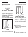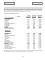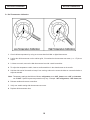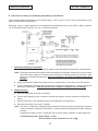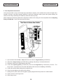
1
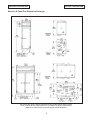
REACH-IN, ROLL-IN, ROLL-THRU &
PASS-THRU WARMERS
OWNERS MANUAL
(For “Quick Navigation”, Click On Topics or Sections Highlighted In Blue)
★
DESCRIPTION
★
INSTALLATION
★
OPERATION
★
MAINTENANCE
★
PARTS LISTS
★
WIRING DIAGRAMS
Warranty
(Continental USA Only)
The Seller warrants to the original purchaser, equipment manufactured by Seller to be free from defects in material and
workmanship for which it is responsible. The Seller's obligation under this warranty shall be limited to replacing or
repairing at Seller's option, without charge, F.O.B. Sellers factory, any part found to be defective and any labor and
material expense incurred by Seller in repairing or replacing such part, such warranty to be limited to a period of one
year from date of purchase or thirteen months from date of shipment from Seller's factory, whichever is earlier, provided
terms of payment have been fully met. All labor shall be performed during regular working hours. Overtime premium
charges will be at Buyer's expense.
Proof of purchase must be supplied to Seller to validate warranty. This warranty is valid only if equipment is properly
installed, started-up and inspected by the dealer or authorized Victory Service agent.
Removal or alteration of the serial/data plate from any equipment shall be deemed to release Seller from all warranty
obligations or any other obligations, expressed or implied.
This warranty does not cover Thermostat or Defrost Timer calibration and/or adjustment, freight damage, normal
maintenance items outlined in Owner's Manual, adjustment of door mechanisms or replacement of light bulbs, fuses
or batteries.
Any repairs or replacement of defective parts shall be performed by Seller's authorized service personnel. Seller shall
not be responsible for any costs incurred if the work is performed by other than Seller's authorized service personnel.
Reimbursement claims for part(s) or labor service costs must be made in writing. Model, cabinet serial numbers and
installation location must be shown on the claim. A receipted bill from the servicing agency must accompany the claim,
together with full details of the service problems, diagnosis and work performed. Victory reserves sole discretion
whether further documentation on a claim is to be submitted.
Seller shall not be liable for consequential damages of any kind which occur during the course of installation of
equipment, or which result from the use or misuse by Buyer, its employees or others of the equipment supplied
hereunder, and Buyer's sole and exclusive remedy against Seller for any breach of the foregoing warranty or otherwise
shall be for the repair or replacement of the equipment or parts thereof affected by such breach.
The foregoing warranty shall be valid and binding upon Seller if and only if Buyer loads, operates and maintains the
equipment supplied hereunder in accordance with the instruction manual provided to Buyer. Seller does not guarantee
the process of manufacture by Buyer or the quality of product to be produced by the equipment supplied hereunder
and Seller shall not be liable for any prospective or lost product or profits of Buyer.
THE FOREGOING WARRANTY IS EXCLUSIVE AND IN LIEU OF ALL OTHER EXPRESS AND IMPLIED
WARRANTIES WHATSOEVER. SPECIFICALLY THERE ARE NO IMPLIED WARRANTIES OF MERCHANTABILITY
OR OF FITNESS FOR A PARTICULAR PURPOSE.
The foregoing shall be Seller's sole and exclusive obligation and Buyer's sole and exclusive remedy for any action,
whether in breach of contract or negligence. In no event shall Seller be liable for a sum in excess of the purchase price
of the item.
You may register online at www.victory-refrig.com, fax this completed page to (856) 428-7299, or copy and mail form below to Victory.
*NOTE: The following mail-in form or online registration must be filled out and forwarded to Victory by the installer or customer within 10 days
after start-up. Failure to do this will invalidate the warranties. Retain this information for your records.
110 WOODCREST ROAD
CHERRY HILL, NJ 08003-3648
TEL: (856) 428-4200 ● FAX: (856) 428-7299
WARRANTIES NOT VALID UNLESS REGISTERED AT
FACTORY WITHIN 10 DAYS AFTER START-UP DATE.
Cabinet Model No.______________________
Cabinet Serial No._________________
(Data plate information located inside cooler on
the upper left wall)
ORIGINAL DATE OF INSTALLATION __________________________________________________________________
INSTALLATION COMPANY NAME ____________________________________________________________________
STREET _______________________________ CITY _____________________ STATE ______ ZIP CODE___________
DISTRIBUTOR’S NAME_____________________________________________________________________________
STREET _______________________________ CITY _____________________ STATE ______ ZIP CODE___________
RETAIN THIS MANUAL FOR FUTURE REFERENCE
NOTICE
Victory (Manufacturer) reserves
the right to change
specifications at any time.
IMPORTANT
Warranty Registration Card Enclosed.
Failure to Properly Register
Equipment Can Void Warranty !!!!
NOTICE
Please Read The Entire Manual
Carefully Before Installation.
If Certain Recommended Procedures Are Not
Followed, Warranty Claims Will Be Denied !!!!
Machine Serial Number_______________________________
Installation Date_____________________________________
Victory Refrigeration Service Hotline (800) 523-5008
Table of Contents
Page
SECTION 1 - DESCRIPTION ....................................................................................
1
A. Component Function .................................................................................
1
B. Specifications & Dimensions .....................................................................
2-7
SECTION 2 - INSTALLATION ..................................................................................
8
A. Receiving Shipment ..................................................................................
8
B. Uncrating Procedure .................................................................................
8
C. Reducing Depth for Narrow Facility Doorway ..........................................
8-9
D. Locating Your New Warmer .....................................................................
9
E. Installing Legs or Casters .........................................................................
9-10
F. Leveling ..................................................................................................
10
G. Initial Cabinet Set-Up ..............................................................................
10-11
H. Electrical Supply .......................................................................................
11
I. Roll-In Unit Grouting and Sealing .............................................................
12
J. Installation Checklist ................................................................................
12
K. Location of Serial Number / Data Plate ....................................................
12
L. Warranty Cards .........................................................................................
13
SECTION 3 - OPERATION .....................................................................................
14
A. Electrical Control .....................................................................................
14
B. Preheating ..............................................................................................
14
C. Recommended Food Storage Periods ...................................................
15
D. Dial Thermometer Calibration .................................................................
16
E. Setting and Calibrating Digital Display Thermometer ..............................
17
F. Door Adjustment Instructions ..................................................................
18
G. Special Feature Shims for Hinged Door Adjustments ............................
19
SECTION 4 - MAINTENANCE ..............................................................................
20
A. Care of Equipment .................................................................................
20
B. Additional Guidelines Regarding Maintenance .......................................
20
SECTION 5 - PARTS LIST ........................................................................................
21-23
SECTION 6 - WIRING DIAGRAM ...............................................................................
24-26
SECTION 1-DESCRIPTION
SECTION 1-DESCRIPTION
SECTION 1
DESCRIPTION
A. Component Function
1. Doors. Each door has a cylinder lock, recessed handle and self-adjusting magnetic gasket.
a. Door Size. The doors are full length and half length.
*Note: There are only full length doors available for Roll-In and Roll-Thru cabinets.
b. Door Type. The doors are stainless steel.
c. Door Hinges. Cam-lift hinges give the doors their self-closing features.
d. Door Interior Liner is constructed of heavy gauge stainless steel.
2. Heating System. Strip type 750 watt heating elements, operating on 208-240/60/1, having a total of 1500
watts per compartment, are positioned in the cabinet to ensure uniform temperature distribution. Manually
controlled humidity vents are provided in the top of the cabinet.
3. Shelves and Pans.
a. Wire shelves. Heavy-duty wire shelves are adjustable in 1” increments. Shelf clips to support the shelves
are inserted into pilasters on the walls.
b. Pan slides. A wide door opening allows the use of a variety of optional pan slide types for 12” x 20”, 18”
x 26” and 14” x 18” pans and/or trays.
●
Stainless Steel Adjustable Type Pan Slides as shown in Figure 1-2 are adjustable in increments.
●
Steel Rod Type Pan Slide Racks, as shown in Figure 1-2, are bottom supported with 2” centers, or
lip supported with 1-1/2” centers.
4. Cabinet. The cabinet ends and interior are made of brushed aluminum. Fronts are made of stainless steel.
Foamed-in-place polyurethane insulation through the cabinet and doors ensures the ultimate in energy
efficiency.
5. Dial Thermometer. The dial thermometer is standard and is calibrated at the factory.
6. Thermometer Sensing Bulb. The temperature sensing bulb is located in the cabinet in the top right hand
corner.
7. Thermostat Control Bulb (Not Shown). The thermal control is accurately calibrated from 70°F to 180°F
1
SECTION 1-DESCRIPTION
SECTION 1-DESCRIPTION
B. Specifications:
Reach-In & Pass-Thru Warmer Specifications
*Note: Approx. Pass- Thru weights, add 15 %
CHARACTERISTICS
Width,Overall
ONE SECTION
Reach-In
Pass-Thru
26-1/2”
26-1/2”
TWO SECTION
Reach-In
Pass-Thru
52-1/8”
52-1/8”
Depth,Overall(incl. handles)
36-1/8”
39-7/8”
36-1/8”
39-7/8”
Height,Overall(incl. adj. legs)
84”
84”
84”
84”
Depth, Door(s) Open 90°°
58-1/2”
84-5/8”
58-1/2”
84-5/8”
Clear Door Width
21-1/8”
21-1/8”
21-1/8”
21-1/8”
Clear Full Door Height
55-1/4”
55-1/4”
55-1/4”
55-1/4”
Clear Half Door Height
25-3/8”
25-3/8”
25-3/8”
25-3/8”
21.5
23.7
46.5
48.0
Number of Full Door(s)
1
2
2
4
Number of Half Door(s)
2
4
4
8
Number of Shelves
3
3
6
6
Shelf Area (sq. feet)
17.1
17.1
36.0
36.0
Capacity Net (cu. ft.)
Volts, Cycles, Phase
208 - 230/60/1
Feed Wires
2
2
2
2
15 Amps
15 Amps
20 Amps
20 Amps
Max. Fuse Size T.D.
Heater Watts
per Section( @ 230V )
Total Wattage
(Heaters & Fan @ 230V )
Total Amperes
CRATED DIM. & WTS.
208 - 230/60/1
1440
1440
1440
1440
1550
1550
3000
3000
6.7
6.7
13.0
13.0
Height
87”
87”
87”
87”
Width
36-1/2”
36-1/2”
63-5/8”
63-5/8”
Depth
44-3/4”
44-3/4”
44-3/4”
44-3/4”
82.2
82.2
143.3
143.3
Stainless Steel
390 lbs
390 lbs
640 lbs
640 lbs
Stainless Steel / Aluminum
370 lbs
370 lbs
600 lbs
600 lbs
Aluminum
350 lbs
350 lbs
580 lbs
580 lbs
Cubic Feet
2
SECTION 1-DESCRIPTION
SECTION 1-DESCRIPTION
Reach-In & Pass-Thru Dimension Drawings:
We reserve the right to change specifications and product design without notice.
Such revisions do not entitle the buyer to correspond changes, improvements
additions or replacements for previously purchased equipment.
3
SECTION 1-DESCRIPTION
Specifications:
SECTION 1-DESCRIPTION
Extra Wide Warmer Specifications
*Note: Approx. Pass- Thru weights, add 15 %
CHARACTERISTICS
Width,Overall
ONE SECTION
Reach-In
Pass-Thru
31-1/4”
31-1/4”
TWO SECTION
Reach-In
Pass-Thru
58-3/8”
58-3/8”
Depth,Overall(incl. handles)
36-1/8”
39-7/8”
36-1/8”
39-7/8”
Height,Overall(incl. adj. legs)
84”
84”
84”
84”
Depth, Door(s) Open 90°°
60”
87-5/8”
60”
87-5/8”
Clear Door Width
22-1/2”
22-1/2”
22-1/2”
22-1/2”
Clear Full Door Height
55-1/4”
55-1/4”
55-1/4”
55-1/4”
Clear Half Door Height
25-3/8”
25-3/8”
25-3/8”
25-3/8”
24.4
26.2
52.0
55.6
Number of Full Door(s)
1
2
2
4
Number of Half Door(s)
2
4
4
8
Number of Shelves
3
3
6
6
Shelf Area (sq. feet)
19.1
19.1
38.2
38.2
Capacity Net (cu. ft.)
Volts, Cycles, Phase
208 - 230/60/1
Feed Wires
2
2
2
2
15 Amps
15 Amps
20 Amps
20 Amps
Max. Fuse Size T.D.
Heater Watts
per Section( @ 230V )
Total Wattage
(Heaters & Fan @ 230V )
Total Amperes
CRATED DIM. & WTS.
208 - 230/60/1
1440
1440
1440
1440
1550
1550
3000
3000
6.7
6.7
13.0
13.0
Height
87”
87”
87”
87”
Width
36-1/2”
36-1/2”
63-5/8”
63-5/8”
Depth
44-3/4”
44-3/4”
44-3/4”
44-3/4”
82.2
82.2
143.3
143.3
Stainless Steel
435 lbs
435 lbs
700 lbs
700 lbs
Stainless Steel / Aluminum
415 lbs
415 lbs
655 lbs
655 lbs
Aluminum
395 lbs
395 lbs
635 lbs
635 lbs
Cubic Feet
4
SECTION 1-DESCRIPTION
SECTION 1-DESCRIPTION
Extra Wide Reach-In & Pass-Thru Dimension Drawings:
We reserve the right to change specifications and product design without notice.
Such revisions do not entitle the buyer to correspond changes, improvements
additions or replacements for previously purchased equipment.
5
SECTION 1-DESCRIPTION
SECTION 1-DESCRIPTION
Specifications:
Roll-In Warmer Specifications
*Note: Approx. Pass- Thru weights, add 15 %
Width,Overall
ONE SECTION
Roll-In
Roll-Thru
36-1/2”
36-1/2”
TWO SECTION
Roll-In
Roll-Thru
68-7/8”
68-7/8”
Depth,Overall(incl. handles)
36-1/8”
39-7/8”
36-1/8”
39-7/8”
Height,Overall(incl. adj. legs)
84”
84”
84”
84”
Depth, Door(s) Open 90°°
65-1/4”
98-1/8”
65-1/4”
98-1/8”
Depth, Case Over Ramp
35-7/16
38-1/2”
35-7/16”
38-1/2”
Clear Door Width
27-3/4”
27-3/4”
27-3/4”
27-3/4”
Clear Full Door Height
65-1/4”
65-1/4”
65-1/4”
65-1/4”
33.6
36.2
67.2
72.4
Number of Full Door(s)
1
2
2
4
Volts, Cycles, Phase
208 - 230/60/1
CHARACTERISTICS
Capacity Net (cu. ft.)
Max. Fuse Size T.D.
Feed Wires
Heater Watts
per Section( @ 230V )
Total Wattage
(Heaters & Fan @ 230V )
208 - 230/60/1
15 Amps
15 Amps
20 Amps
20 Amps
2
2
2
2
1440
1440
1440
1440
1550
1550
3000
3000
6.7
6.7
13.0
13.0
Height
87”
87”
87”
87”
Width
41-3/4”
41-3/4”
74-5/8”
74-5/8”
Depth
44-3/4”
44-3/4”
44-3/4”
44-3/4”
94.1
94.1
168.1
168.1
Stainless Steel
460 lbs
460 lbs
870 lbs
870 lbs
Stainless Steel / Aluminum
440 lbs
440 lbs
810 lbs
810 lbs
Aluminum
400 lbs
400 lbs
770 lbs
770 lbs
Total Amperes
CRATED DIM. & WTS.
Cubic Feet
6
SECTION 1-DESCRIPTION
SECTION 1-DESCRIPTION
Roll-In & Roll-Thru Dimension Drawings:
We reserve the right to change specifications and product design without notice.
Such revisions do not entitle the buyer to correspond changes, improvements
additions or replacements for previously purchased equipment.
“End Of Section, Click Here For Table Of Contents”
SECTION 2-INSTALLATION
SECTION 2-INSTALLATION
SECTION 2
INSTALLATION
A. Receiving Shipment
1. Removing Doors. (Refer to Figure 2-1)
Upon arrival, examine the exterior of the shipping carton
for any signs of rough handling. It is advisable that the
shipping carton be partially removed, in order to examine
for any possible concealed damages which might have
occurred during shipment.
a. Open door to approximately 90°
b. Lift door straight up and off hinges
If no damages are evident, replace shipping carton by
restapling or nailing to skid in order to protect the cabinet
during local delivery. If the cabinet is damaged, it should
be noted on the delivery slip or bill of lading and signed
to that effect. A claim must be filed immediately against
the carrier indicating extent and estimated cost of
damage incurred.
All units are performance tested and thoroughly
inspected prior to shipment. Upon leaving the factory, all
units are in perfect condition and the carrier signs to this
effect.
B. Uncrating Procedure
WARNING
Figure 2-1
Door Removal
DO NOT , Under Any Circumstances,
Lay Your New Equipment Down On
Either The Back, Front or Sides
2. Front Grille
a. On grilles with dial thermometers or electrical
components, disconnect capillary tubing and/or
electrical connections before completely
removing air grille.
See instructions printed on shipping carton. Remove top
cap and cardboard side walls. Remove wooden skid.
The shipping skid must be removed by tipping the model
from side to side. Remove the shipping bolts while the
model held in one direction, then repeating this
procedure when the model is held in the opposite
direction.
Note: The thermometer capillary tube and sensing bulb
are attached to cabinet. If the grille has to be removed,
caution must be taken when removing the capillary tube.
b. Remove the front air grille by removing the two
(2) sheet metal screws on the inside of the grille
at each end. Push up at the bottom of the grille
to disengage the rivets from the keyhole slots
and pull forward.
C. Reducing Warmer Depth For Narrow Facility
Doorway
In order to pass through a narrow doorway or restricted
area, the following may be removed to reduce the overall
depth of the cabinet to a minimum of 32-1/2” deep:
8
SECTION 2-INSTALLATION
SECTION 2-INSTALLATION
3. Hinges and Lock Keeper
a. Refer to Figure 2-2. To remove the hinge base
from the cabinet fascia, unscrew the three
machine screws.
On the upper hinge, you will notice a light switch with six
inch red lead wires. Tape switch to interior door jamb.
Do not remove wires.
When reinstalling upper hinge, nest switch into bottom of
base and fasten carefully to fascia.
Figure 2-3
Lock Keeper
D. Locating Your New Warmer
The following conditions should be considered when
selecting a location for your warmer:
1. Clearance - There must be a minimum clearance of
10” between the top of the warmer and the ceiling of
the room.
2. Floor Load - The floor on which the cabinet will rest
must be free of vibration and suitably strong enough
to support the combined weights of the cabinet plus
the maximum product load which might be placed
into it. To estimate the possible product load weight,
it is generally conceded that a safe figure is 35
pounds for each net cubic foot of storage space. For
example, a 47 cubic foot cabinet could hold
approximately 1,645 pounds of product (47 x 35 =
1,645).
Figure 2-2
Hinge and Light Switch
b. To remove lock keeper (“D” shaped metal casting
for lock bolt) use a 5/16” open end wrench.
Remove the two #10-32 screws attaching keeper
to fascia. Reverse procedure to reinstall. Refer
to Figure 2-3.
3. Ventilation - Vent assemblies are supplied with
each cabinet to assist in the warming process of
foods. The vent knob is located inside the warmer
cabinet at the top. By turning the knob left or right,
moisture within the cabinet can be controlled.
E. Installing Legs or Casters
Warmers are shipped with legs or casters. Legs and
casters are the 1/2” single stud mount type and require
no tools for installation. Simply screw them into the
threaded holes located in the braces on the case bottom.
9
SECTION 2-INSTALLATION
SECTION 2-INSTALLATION
Tilt the cabinet in one direction approximately eight
inches and block it securely to keep it from falling. Use
several pieces of 2” x 4” lumber or other suitable material.
Screw the two left right legs in until snug with brace.
Repeat this procedure to install the other legs.
WARNING
DO NOT , Under Any Circumstances,
Lay Your New Equipment Down On
Either The Back, Front or Sides
F.
Leveling
Cabinet must be leveled when installed. This is
accomplished by rotating the foot of the leg with an
adjustable wrench. Failure to level your cabinet may
result in doors not sealing, closing properly or
condensate water not draining properly.
G. Initial Cabinet Set-Up
Units are shipped with shelves or pan slides. These
items are secured to the rear of the cabinet directly on
the wood skid. Two (2) keys are supplied per unit and
are taped to the door handle. An additional key is taped
to the top of the air grille.
Figure 2-4
Installing Shelf Clip Supports Into Pilasters
3. Pan Slides (Optional)
a. Stainless Steel Angle Type Pan Slides.
(Refer to Figures 2-5 & 2-6)
Cabinets may be supplied with removable stainless steel
angle pan slides, and are available in the following:
●
Type “A” for one 18” x 26” pan or two 14” x 18”
pans Bottom Support
●
Type “B” for one 18” x 26” pan or two 14” x 18”
pans Lip Support
1. Cleaning Cabinet
CAUTION:
DO NOT Use Volatile Cleaning Solvents!
Never scour any part of your new cabinet. Scouring
powders or chemicals may cause damage by scratching
or dulling the surface finish. Prior to placing your new
warmer and all shelves, pans and slides into operation, it
is advisable that the interior be washed thoroughly with a
mild detergent and water solution. Rinse with clear water
and a sanitizing solution. Allow cabinet to dry.
2. Installing Shelves
All models with shelves are supplied with pilasters and
shelf clip supports. The pilasters have 3/8” square
openings on 1” centers. Shelves are easily installed by
inserting the shelf support clips into the pilasters. Insert
the clips as shown in Figure 2-4. The clips fit tightly so it
may be necessary to push the clips into their holes. Align
the shelf so that the smaller fill wires run from front to rear
and rest on the shelf clips.
10
●
Type “C” for 12” x 20” pans, Lip Support
●
Type “A/C” for one 18” x 26” pan, 12” x 20” pans
or two 14” x 18” pans, Bottom Support
SECTION 2-INSTALLATION
SECTION 2-INSTALLATION
b. Steel Rod Type Pan Slide Racks (Refer to
Figure 2-7)
Steel rod type pan slide racks are also available. They
are designed to accommodate 18” x 26” sheet pans as
follow:
●
Bottom Support Pan Slide Rack on 2” centers
●
Lip Support Pan Slide Rack on 1-1/2” centers
Uprights for mounting the steel rod type pan slide racks
are factory installed.
Figure 2-5
Angle Type Pan Slides
The appropriate amount of uprights are already
installed,when ordered with your cabinet from the factory.
Pan slides cannot be attached to the standard shelf
pilaster. Pan Slide uprights have 1/2” square holes on 1”
centers.
To install an individual slide, locate the appropriate
square holes at the desired height. (A complete section
of slides should be installed by starting at the bottom).
Insert tabs of the slide into the uprights and apply
pressure in a downward direction until the tab fully
engages the upright. Refer to Figure 2-6.
Figure 2-7
Steel Rod Type Slides
H. Electrical Supply
The wiring should be done by a qualified electrician in
accordance with local electrical codes. A separate
ground wire must be supplied for all installations.
A properly wired warmer will assure proper operation.
Supply voltage requirements are on the cabinet serial
plate.
It is recommended that a direct, properly fused line of the
proper size wire be installed from the main supply to your
warmer.
Low or high voltage can detrimentally affect the warmer
unit and thereby void its warranty.
All warmer electrical systems are internally grounded. It
is recommended that a bonding braid be secured at the
base of the warmer and carried to a water pipe to
complete the ground.
Figure 2-6
Installing Stainless Steel Angle Type Pan Slides
11
SECTION 2-INSTALLATION
SECTION 2-INSTALLATION
I.
Roll-In Unit Grouting and Sealing
4. Using a wide blade putty knife, taper the grout to a
feather edge.
NOTE: It is an N.S.F. requirement that Roll-In models
are sealed to the floor upon installation.
Note: The procedure for setting and grouting the two
section model illustrated below is typical and also
applies to one sections.
WARNING
CARE SHOULD BE TAKEN TO AVOID
GOUGING OR MARRING SURFACE
OR EDGES OF ALUMINUM RAMP.
1. Locate Roll-In model in exact position in which it is to
set permanently.
Note: For reasons of clarity, the illustrations
are shown without doors. Do not remove doors
when installing roll-in models.
Figure 2-9
Wood Form Acting As A Retainer
5. A tube of silicone sealer having an applicator type
nozzle is highly suited for sealing Roll-In models to
floor. Cut off a small portion of the applicator nozzle
and apply a small uniform bead completely around
the base of the unit, including the chisel type
ramp(s). Silicone sealer may be feathered at leading
edge of chisel ramp(s) within a given period of time
after it has been applied. Read and follow the
instructions on the tube carefully.
2. Level unit, inserting metal shims under unit where
required. It is important that an accurate carpenters
level be used when leveling cabinet. See Figure 2-8.
J. Installation Checklist
After the cabinet has been installed, leveled and cleaned
as described in the preceding paragraphs, refer to the
following checklist prior to start-up.
Figure 2-8
Leveling Cabinet
●
Full voltage of the correct type, on a line not affected
by the operation of other electrical appliances, must
be available for proper operation.
●
Cabinet must be properly leveled.
K. Location of Serial Number / Data Plate
The serial data plate is mounted on the upper left interior
wall.
3. Construct a wood form to act as a retainer for the
grouting compound around the entire base of the
cabinet. See Figure 2-9. Pour the grout mixture at
various intervals around the form to assure complete
fill under the cabinet.
NOTE: When ordering replacement part, you must
include the complete cabinet model and serial numbers.
12
SECTION 2-INSTALLATION
SECTION 2-INSTALLATION
L. Warranty Cards
Locate the warranty cards at the front of this manual. Fill
out all three cards (“Factory Record Card”, “Distributor’s
Record Card” and “Customer’s Record Card”) and mail
the Factory and Distributor’s cards as directed. The
Customer’s card must be retained by the customer.
“End Of Section, Click Here For Table Of Contents”
SECTION 3-OPERATION
SECTION 3-OPERATION
SECTION 3
OPERATION
A. Electrical Control
The temperature of the Victory Warming Cabinet is maintained by means of a thermostat which can be adjusted to give
the desired temperature 80°F -180°F. The thermostat setting determines the temperature at which the heating
elements are de-energized by the control.
The dial thermometer indicates the approximate temperature within the cabinet. It can be recalibrated to read actual
cabinet temperature, but this is not necessary. The proper thermostat setting must be obtained by experiment and
after it is determined at which setting food keeps the best. It will always maintain the same temperature at the same
setting.
Do not change the setting once it has been correctly determined, unless it is necessary to keep an entirely different
type of food. In heating up a cold unit, do not change the setting, as it does not increase the speed of preheating. It
only changes the temperature at which the current will be automatically turned off.
B. Preheating
Food should not be placed in a cold Victory Warming Cabinet. To preheat the Warming Cabinet, turn the knob on the
thermostat, which is also used as the “on” and “off” switch, one hour before it will be needed. When turning on the
switch or thermostat, set it at the temperature desired. It will not preheat any faster by setting the knob up to full heat.
If the food has been cooked in the same pan in which it will be served, it should be left in the same pan when being
placed in the Warming Cabinet. However, if food is cooked and served in different pans, the food should be panned
as soon as the cooking is completed and placed in the warmer cabinet. Although, the two methods mentioned may
not necessarily pertain to the requirements of daily foodservice activity, another approach for good food quality is to
place the food directly to a serving counter after cooking. The Warmer Cabinet keeps the food in good condition during
the interval between cooking and serving. It is recommended that food should be stored within the cabinet and in its
original pan in which it will be served.
The food should be preferably be placed in the cabinet while hot, but not until it stops giving off steam (if
excessive, use a lid on pots or pans). It is possible to reheat some food without further deterioration if sufficient time
is allowed for the heat to slowly penetrate the entire mass.
Most food can be kept in best condition at a temperature of approximately 175°F, but the exact temperature varies
depending upon the kind of food and method of its preparation; therefore, it is impossible to give any exact instructions
which will fit all conditions. It is necessary to experiment by increasing or decreasing the temperature of the unit until
you find the temperature at which the majority of the food kept in the unit will keep in the best condition. Once this
setting is determined, the control should always be kept at this setting.
Some food, such as breaded meats, fish, etc., when kept at proper temperature, require less degree of moisture in the
cabinet to prevent sogginess. For this reason, all cabinets are equipped with vents or dampers. The damper should
be opened for such food by turning the knob in the desired direction for opening and closing. This knob opens or
closes the vent in the top of the cabinet. By looking into the into the cabinet when operating the knob, you can fully
understand its function and adjustment.
14
SECTION 3-OPERATION
SECTION 3-OPERATION
Some foods can be kept in good condition much longer than others, and certain foods cannot be satisfactorily kept at
all in any manner. French fried potatoes, roasts, waffles and similar foods, where the outside must be crisp and centers
steaming hot, must be prepared immediately before serving. Do not expect the impossible from the Warming Cabinet,
but if used intelligently, it will keep food over a longer period of time and with less deterioration than is possible with
any other equipment. By reducing the deterioration between the time the food is cooked and the time it is served, the
Warming Cabinet will assure serving the food to the customer in proper condition.
C. Recommended Food Storage Periods
Product
Longest
Time Kept
Average
Time Kept
Approximate
Temp. (°F)
2 hrs.
2 hrs.
8 hrs.
6 hrs.
1 hr.
6 hrs.
6 hrs.
8 hrs.
6 hrs.
6 hrs.
10 hrs.
30 min.
1 hr.
5 hrs.
3 hrs.
30 min.
3 hrs.
2 hrs.
4 hrs.
4 hrs.
3 hrs.
5 hrs.
170-180
140-150
140-150
170-180
160
170-180
170-180
140-150
160
170-180
150
8 hrs.
3 hrs.
1 hr.
8 hrs.
6 hrs.
5 hrs.
6 hrs.
4 hrs.
8 hrs.
3 hrs.
4 hrs.
8 hrs.
12 hrs.
4 hrs.
4 hrs.
4 hrs.
6 hrs.
3 hrs.
4 hrs.
2 hrs.
30 min.
4 hrs.
4 hrs.
3 hrs.
3 hrs.
2 hrs.
4 hrs.
2 hrs.
2 hrs.
3 hrs.
4 hrs.
2 hrs.
2 hrs.
2 hrs.
2 hrs.
2 hrs.
170-180
170-180
150-175
170-180
180
170-180
160-175
170-180
150-180
160-180
170-180
140-150
*Crispy or Dry Foods
Baked Potatoes
Corn Sticks
Crackers
Chicken Pies
Club Sandwiches (Wrapped)
Fried Chicken
Fried Seafood
Hard Rolls
Hot Mince or Apple Pie
Meat Pies
Popcorn and Potato Chips
*Moist Foods
Baked Beans
Baked Stuff Lobster
Biscuits
Casserole (without top crust)
Chop Suey
Deviled Crabs
Frankfurter
Hash
Hot Puddings
Mashed Potatoes
Meats - ready for serving
Muffins and Corn Bread
Soft Rolls
Stews - ready for serving
Sweet Rolls
Stuffed Pork Chops
Vegetables - ready for serving
Turkey with Dressing
170-180
140-150
170-180
170-180
175
Rolls that are extremely rich in butter content cannot be kept for any extended time without the butter becoming rancid.
Rolls with sugar icing may require a lower temperature to prevent the icing from running.
15
SECTION 3-OPERATION
SECTION 3-OPERATION
D. Dial Thermometer Calibration:
1. Check cabinet temperature by using an accurate hand held dial or digital thermometer.
2. Look at the dial thermometer on the cabinet grille, if it matches the thermometer test meter (+ or -1°F)do not
adjust.
3. It it does not match, remove the dial thermometer lens with a small screwdriver.
4. To adjust the temperature needle, insert a small screwdriver in the slotted screw on the needle.
5. Hold the wide end of the needle to keep it from moving, and turn the screw clockwise or counterclockwise to
adjust as needed.
*Note: Temperature settings should be as follows; refrigerators set at 38°°F, freezers set at 0°°F, and warmers
set at 180°°F. Special request temperatures may vary. Example: 28°°F refrigerators, -10°°F freezer, etc.
6. Release needle and remove screwdriver.
7. Verify new needle setting with thermometer test meter.
8. Replace dial thermometer lens.
16
SECTION 3-OPERATION
SECTION 3-OPERATION
E. Instructions for Setting and Calibrating Digital Display Thermometer:
Victory’s digital display thermometers have a sensing range of -40°F to 220°F (-40°C to 105°C) which allows it to be
used in a wide variety of applications.
Setting the control for proper application is accomplished by installing the jumper on the “HI” or “LO” pin position.
“HI” for Refrigerators and Freezers, and “LO” for Warming Cabinets.
1. Calibrating the Display Temperature
The alarm switch must be placed in the right (T) position when calibrating the temperature as shown above.
*Note: The digital thermometer has a built-in delay and displays a temperature change every two (2) minutes.
This prevents the display from showing erratic temperature readings during door openings. When
making any calibration adjustments, allow two minutes for the delay to register temperature
changes.
a. Using a reliable dial or digital thermometer, place the sensing device in the center area of the cabinet.
b. Turn the temperature calibration screw clockwise to increase the temperature, or counter-clockwise to
decrease the temperature. Wait two minutes for the display to respond to the new settings.
2. Setting the Alarm
a. Move the alarm switch to the left (AL) position.
b. Turn the alarm adjusting screw clockwise to increase the setting or counter-clockwise to decrease the
setting.
c. Set the temperature to the appropriate range for the application as shown above.
d. Move the alarm switch to the right (T) position.
*Note: The alarm is indicated by a flashing display temperature and occurs when temperatures rise above
the alarm setting for refrigerators and freezers, or when temperatures drop below the alarm setting for
warmers.
Changing the jumper to read in “Centigrade” will not require further calibration or alarm adjustment.
Troubleshooting Probe - Red to Black = 5 volts
Black to White= Linear Temperature (ie. 34 is 34°°)
17
SECTION 3-OPERATION
SECTION 3-OPERATION
F. Door Adjustment Instructions:
Victory has provided a unique self-closing hinge assembly for majority of the cabinets that consist of hinged doors.
Instead of having to deal with complex methods for good door alignment and/or proper door gasket sealing, the
features on the hinge assembly (PN 10685101) makes the task very easy.
When adjustment of the door gasket seal or alignment is desired, fine-tuning can be accomplished with the Adjusting
Plate (pn 50520104). Check the instructions that follow.
1. Open the door between 90°° to 180°° and lift the door from the hinge brackets (pn 50520103).
2. Slide off the hinge cover(s) (pn 50520105) by grasping and pulling in a downward direction.
3. Replace the door on the hinge brackets and close.
4. Locate the adjusting plate (pn 50520104) inside of the hinge barrel (pn 50520102) of choice. The
hinge barrel is placed on the door itself and attached with at least two screws (pn 50678801).
5. Loosen the screws without taking them completely out.
6. Close door and adjust to the fascia of the cabinet.
7. Slowly push or pull the door until the gasket properly aligns and evenly seals to the cabinet fascia.
8. Tighten screws on the hinge barrel.
9. Place hinge covers.
18
SECTION 3-OPERATION
SECTION 3-OPERATION
G. Special Feature Shims for Hinged Door Adjustments:
There are a couple of special feature shims that assist with the adjustment of hinged doors using the self-closing hinge
assembly (pn 10685101). These items can be used as a second or third option if additional adjustment is required.
Refer to the shim descriptions below and their purpose.
1. Fascia Shim (pn 05072701) - The fascia shim is used to help extend the “Hinge Bracket” (pn 50520103)
in a forward direction when the door gasket needs to be loosened from or accurately tightened to the
cabinet fascia.
When using this shim, build-up the hinge bracket by inserting one at a time until the forward extension
supports an acceptable gasket seal to the cabinet. Hinge bracket adjustments can be different from door
to door.
Make sure that the open end of the slot shaped cut -out is always facing towards the door with the hinge
switch assembly wires going through it. If the wires are not put through the slot shaped cut-out, there could
be a great possibility of wire damage to the hinge switch assembly.
2. Leveling Shim (pn 50538601) - The leveling shim is used to raise the door in an up or down direction. This
part is placed behind the the hinge barrel (pn 50520102) with the open ends of the three slot shaped cutout’s facing towards the cabinet. While adjusting the top or bottom screws per hinge barrel, the door will go
in a specific direction. Check out the following information below and refer to page 18 for pictures.
a.) Top Hinge Barrel with Leveling Shim - Adjusts the door in a downward direction.
b.) Bottom Hinge Barrel with Leveling Shim - Adjusts the the door in an upward direction.
*Note: When inserting and/or adjusting the leveling shim, avoid taking the screws completely out of the door.
Try to make a gap wide enough to slip the shim in between the hinge barrel and the door, then tighten
the screws until the leveling process of the door is satisfactory and stable.
“End Of Section, Click Here For Table Of Contents”
SECTION 4-MAINTENANCE
SECTION 4-MAINTENANCE
SECTION 4
MAINTENANCE
A. Care of Equipment
The cabinet should be cleaned each night. In doing this, avoid using an excessive amount of water. A damp cloth and
any good grease solvent, or soap, should remove any food which has been accidentally spilled into the cabinet. Turn
off power with thermostat switch when through using the unit for the day.
Occasionally, if you have been using the cabinet with the vent open, leave the heat turned on for several hours with
the cabinet empty, vents open and the door propped open. This will assist in driving off any excessive moisture which
might have collected in the Warmer Cabinet.
Should the unit fail to heat, first ascertain if the fuses in the are in tact. If the fuses are good and the until still will not
heat, call a competent electrician.
B. Additional Guidelines Regarding Maintenance
1. Avoid the Three Corrosives
There are three (3) corrosives capable of breaking down stainless steel and will cause damage to the cabinets
interior and exterior surfaces. DO NOT USE the following:
a. Mechanical Abrasion - are those things that scratch steel’s surface. Steel pads, wire brushes and
scrapers are examples.
b. Water - comes in degrees of hardness. Depending on what part of the country you live in, you may
have hard or soft water. Spots may be left by hard water. When hard water is heated, deposits are left
behind that will breakdown and rust stainless steel. Deposits from food preparation and service can also
contribute to breakdown without proper removal.
c. Chlorides - are in water, food and table salt just to name a few. The worst of chlorides come from
household and industrial cleaners.
2. Use of Proper Tools and Cleaning Methods
When cleaning your cabinet, remember to use non-abrasive tools. Soft cloths and plastic scouring pads will not
harm stainless steel. Stainless Steel pads can be used, but scrubbing motion must be in direction of polishing
marks.
Some stainless steel’s polishing lines or “grain” are clearly visible. Always scrub in a motion parallel to the
polishing lines as previously mentioned. If the polishing lines cannot be seen, use only a soft cloth or plastic
scouring pad.
3. Treat Hard Water
Softening hard water can substantially reduce deposits. Certain filters can be installed to remove corrosive
elements. If unsure of proper water treatment, contact a local water treatment specialist.
“End Of Section, Click Here For Table Of Contents”
SECTION 5-PARTS LIST
SECTION 5-PARTS LIST
SECTION 5
PARTS LISTS
21
SECTION 5-PARTS LIST
SECTION 5-PARTS LIST
1 & 2 Section Standard, Extra Wide, Roll-In & Half Door
“Series 6 & 7” Warmers Parts Lists
(*Note: For other parts not presented on the list, please consult factory with cabinet model & serial number)
Part No.
Description
Controls & Electrical
50307301
50181302
50181301
10501601
50303101
50303201
50561602
50701901
50701902
50397802
50707211
50707311
50707313
Temperature Control
Knob with Numbers
Knob - Vent without Numbers
Vent Assembly (knob, vent, stud and assembly)
Heat Element 220 Volt (Standard)
Heat Element 115 Volt (Optional)
Heater Safety, High-Limit (*replaces pn 50561601 which is no longer available)
Blower Motor with Squared Case 208V (Standard)
Blower Motor with Squared Case 115V (Optional)
2” Dial Thermometer
Digital Thermometer Display Board with Probe
115V Transformer for Digital Thermometer (Optional)
220V Transformer for Digital Thermometer (Standard)
Doors and Door Parts
10533302
10533301
05082904
50601506
Assembly Door, Right Hinged, Long - for Reach-In Model
Assembly Door, Left Hinged, Long - for Reach-In Model
Stainless Steel Liner, Long
Gasket, Full Length
10533402
10533404
10533401
10533403
05083004
50601505
Assembly Door, Half Door, Lower Right Hinged - for Reach-In Model
Assembly Door, Half Door, Upper Right Hinged - for Reach-In Model
Assembly Door, Half Door, Lower Left Hinged - for Reach-In Model
Assembly Door, Half Door, Upper Left Hinged - for Reach-In Model
Stainless Steel Liner, Half Door
Gasket, Half Door
10517202
10517201
05082902
50601504
Assembly Door, Right Hinged, Long - for Extra Wide Reach-In Model
Assembly Door, Left Hinged, Long - for Extra Wide Reach-In Model
Stainless Steel Liner, Long - for Extra Wide Reach-In Model
Gasket, Full Length - for Extra Wide Reach-In Model
10517302
10517304
10517301
10517303
05083002
50601503
Assembly Half Door, Lower Right Hinged - for Extra Wide Model
Assembly Half Door, Upper Right Hinged - for Extra Wide Model
Assembly Half Door, Lower Left Hinged - for Extra Wide Model
Assembly Half Door, Upper Left Hinged - for Extra Wide Model
Stainless Steel Liner, Half Door - for Extra Wide Model
Gasket, Half Door - for Extra Wide Model
22
SECTION 5-PARTS LIST
SECTION 5-PARTS LIST
1 & 2 Section Standard, Extra Wide, Roll-In & Half Door
“Series 6 & 7” Warmers Parts Lists
(*Note: For other parts not presented on the list, please consult factory with cabinet model & serial number)
Part No.
Description
Doors and Door Parts (continued)
10517402
10517401
05083102
50316402
50267702
Assembly Door, Right Hinged, Long - for Roll-In Model
Assembly Door, Left Hinged, Long - for Roll-In Model
Stainless Steel Liner - for Roll-In Model
Gasket, Roll-In - Long
Wiper Seal
Cabinet Parts
04087302
04328502
04330402
Cover, Heating Element Wall 25-7/8” One & Two Section (ck. length - 2 sizes)
Cover, Center 2 Section with Hem - 25-78” for Pan Slide Hole
Cover, Center 2 Section without Hem - 25-7/8” for Pan Slide Hole
09340801
09340902
09340901
09340802
09340803
09341001
09341002
50598102
50598202
50597107
50673901
10685101
50671801
50586002
50316501
06031901
Stainless Steel Trim, Top or Bottom - for Reach-In Model
Stainless Steel Trim, Side, Long Door - for Reach-In Model
Stainless Steel Trim, Side, Half Door - for Reach-In Model
Stainless Steel Trim, Top or Bottom - for Extra Wide Model
Stainless Steel Trim, Top - for Roll-In Model
Stainless Steel Trim, Left Hand Side - for Roll-In Model
Stainless Steel Trim, Right Hand Side - for Roll-In Model
Keeper, Single Door
Keeper, Double Door
Lock & Key Assembly
Handle, Door
Assembly, Hinge (2 per door)
Leg, Black Plastic
Leg, Stainless Steel (screw-in type)
Ramp, Roll-In (1 per section)
Cart Guide (2 per section)
05098804
05098805
10531002
10521012
10531004
10531014
10531006
10531016
Upper Case End, Stainless Steel
Upper Case End, Aluminum
Grille - 1 Section Reach-In (Stainless Steel)
Grille - 1 Section Reach-In (Stainless Steel)
Grille - 1 Section Reach-In, Extra Wide (Stainless Steel)
Grille - 1 Section Reach-In, Extra Wide (Stainless Steel)
Grille - 1 Section Roll-In (Stainless Steel)
Grille - 2 Section Roll-In (Stainless Steel)
“End Of Section, Click Here For Table Of Contents”
SECTION 6-WIRING DIAGRAMS
SECTION 6-WIRING DIAGRAMS
SECTION 6
WIRING DIAGRAMS
24
SECTION 6-WIRING DIAGRAMS
SECTION 6-WIRING DIAGRAMS
1 & 2 Section Warmer 208/230V (Standard)
25
SECTION 6-WIRING DIAGRAMS
SECTION 6-WIRING DIAGRAMS
1 & 2 Section Warmer 208/230/115V (Optional)
“End Of Section, Click Here For Table Of Contents”
VICTORY REFRIGERATION
110 Woodcrest Road
Cherry Hill, NJ 08003
Phone (856) 428-4200 Fax (856) 428-7299
Website: www.victory-refrig.com
E-Mail: [email protected]
[email protected]
or
[email protected]
Manual Part Number: 50785901
Rev: 03
Print Date: 4/30/02
Price: $15.00
Website: www.agafoodservice.com