1
. i.
.
. 4q
o
'. ,
q
_ '_,, _ _ _ _ _ _ _ _.~IiL_D~·.~_-----:--_ __
'\ OPERATORS
I
MANUAL,
D~-NET'- DiESEL~-G-ENE'RATORSci
,-.'.-.-,-----_
-~._
_,
. ' _ ' .__ '
__ .. '"
.__ _..
"
-
--.-- . ....
'~ __..
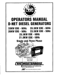
;, 33.0KW-60Hz
. '26.0KW-50Hz
.
.
,
-,
-.'~.
. -
-
28.5KW-60Hz
23.5KW-50Hz
- .
~,.
,__
I
I
•
25.5KW-60Hz
21.0KW-50Hz·
. EDE and EDEA MODELS
SINGLE' andTliHASE
•• 1
WESTERBEKE CORPORAT/eJN. MYLES STANDISH INDUSTRIAL PARK
150 JOHN HANCOCK ROAD· TAUNTON MA 02780-7:]19· TEL. 1-508-823-7677
FAX 1~508-884.g688. WEBSITE: Www.WESTERBEKE.COM
,
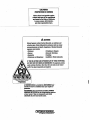
·CALIFORNIA
PRDPDSITION 65 WARNING
Marine diesel and gasoline engine
exhaust and some of its constituents
are known to the State of California
to cause cancer, birth defects,
and other reproductive harm •
.----.-----.!=======~-----
A WARNING
Exhaust gasses contain Carbon Monoxide, an odorless and
colorless gas. Carbon Monoxide is poisonous and can cause
unconsciousness and death. Symptoms of Carbon Monoxide
exposure can include:
- Throbbing in Temples
-Dizziness
- Muscular Twitching
-Nausea
-Headache
- Vomiting
- Weakness and Sleepiness -Inability to Think Coherently
IF YOU OR ANYONE ELSE EXPERIENCE ANY OF THESE SYMPTOMS,
GET OUT INTO THE FRESH AIR IMMEDIATELY. If sympfDms persist,
seek medical attention. Shut down the unit and dq not restart
until it has been inspected and repaired.
'WARNING
,
Genetaton;; Produce CARBON MONOXIDE
Regu!ar Maintenance Requlred
;-
.
A WARNING DECAL is provided by WESTERBEKE and
should be fixed fD a bulkhead near your engine or
generator.
WESTERBEKE also recommends installing CARBON
MONOXIDE DETECTORS in the living/sleeping quarters
of your vessel. They are inexpensive and easily
obtainable at your local marine store.
Engine,! & Generators
SAFETY INSTRUCTIONS
INTRODUCTION
PREVENT BURNS - FIRE
Read this safety manual carefully. Most accidents are
caused by failure to folklw fundamental rules and
precautions. Know when dangerous conditions exist and
take the necessary precautions to protect yourself, your
personnel, and your machinery.
The following safety instructions are in compliance with
the American Boat and Yacht Council (ABYC) standards.
A WARNING: Fire can cause injury or death!
• Prevent flash fires. Do not smoke or permit flames or
sparks to occur near the carburetor, fuel line, filter, fuel
pump, or other potential sources of spilled fuel or fuel
vapors. Use a suitable container to catch all fuel when
removing the fuel line, carburetor, or fuel filters.
, "---pflEVENTElECTRIC-SHOCK----------.-Elo-not-operate-without-a-Goast-Guard-Approved-flame
arrester. Backfire can cause severe injury or death.
• Do not operate with the air cleaner/silencer removed.
WARNING: Do not touch AC electrical connect/ons
Backfire can cause severe injury or death.
while engine is running, or when connected to shore
• -Do not smoke or permit flames or sparks to occur near
power. Lethal voltage is present at these connections!
the fuel system. Keep the compartment and the
engine/generator clean and free of debris to minimize the
• Do not operate this machinery without electrical
chances of fire. Wipe up all spilled fuel and engine oil.
enclosures and covers in place.
• Be aware - diesel fuel will bum.
• Shut off electrical power before accessing electrical
equipment.
PREVENT BURNS - EXPLOSION
• Use insulated mats whenever working on electrical
equipment.
WARNING: Explosions from fuel vapors can cause
• Make sure your clothing and skin are dry, not damp
injury
or death!
(particularly shoes) when handling electrical equipment.
• Remove wristwatch and all jewelry when working on
• Follow re-fueling safety instructions. Keep the vessels
electrical equipment.
hatches closed when fueling. Open and ventilate cabin
after fueling. Check below for fumes/vapor before
• Do not connect utility shore power to vessels AC
running the blower. Run the blower for four minutes
circuits, except through a ship-to-sho"" double throw
before starting your engine.
transfer switch. Damage to vessels AC generator may
result if this procedure is not followed.
• All fuel vapors are highly explosive. Use extreme care
when handling and storing fuels. Store fuel in a
• Electrical shock results from handling a charged
well-ventilated area away from spark-producing
capacitor. Discharge capacitor by shorting terminals
equipment and out of the reach of children.
together.
• Do not fill the fuel tank(s) while the engine is ronning.
PREVENT BURNS - HOT ENGINE
• Shut off tlie fuel service valve at the engine when servicing
the fuel system. Take care in catching any fuel that might
spill. DO NOT allow any smoking, open flames, or other
WARNING: Do not touch hot engine parts or
sources of fire near the fuel system or engine when
exhaust system components. Arunning engine gets
servicing. Ensure proper ventilation exists when servicing
very hot!
the fuel system.
• Do not alter or modify the fuel system.
• Always check the engine coolant level at the coolant
• Be sure all fuel supplies have a positive shutoff valve.
recovery tank.
• Be certain fuel line fittings are adequately tightened and
free of leaks.
WARNING: Steam can cause Injury or death!
• Make sure a fire extinguisher is installed nearby and is
properly maintained. Be fantiliar with its proper use.
• In case of an engine overheat, allow the engine to cool
Extinguishers rated ABC by the NFPA are appropriate
before touching the engine or checking the coolant.
for all applications encountered in this environment.
A
A
A
A
Engines & Generators
i
SAFETY INSTRUCTIONS
. ACCIDENTAL STARTING
TOXIC EXHAUST GASES
A WARNING: AccIdental starting can cause injury
A WARNING: Carbon monoxide (CO) is adeadly gas!
or death!
• Disconnect the battery cables before servicing the engine/
generator. Remove the negative lead first and reconnect
it last.
• Ensure that the exhaust system is adequate to expel gases
discharged from the engine. Check the exhaust system
regularly for leaks and make sure the exhaust
manifolds/water-injected elbow is securely attached.
• Make certain all personnel are clear of the engine before
• Be sure the unit and its surroundings are well ventilated.
---starting
_ _ _ _ _ _ _ _ _ _ __
Run blowers whelITUnning1he-generator-set-or1lngine;
• Make certain all covers, guards, and hatches are
re-installed before starting the engine.
• Do not run the generator set or engine unless the boat is
equipped with a functioning marine carbon monoxide
detector that complies with ABYCA-24. Consult your
BATTERY EXPLOSION
boat builder or dealer for installation of approved
detectors.
WARNING: Battery explosion can cause injury
• For additional information refer to ABYC T-22
(educational information on Carbon Monoxide).
or death!
A
•
Do not smoke or allow an open flame near the battery
being serviced. Lead acid batteries emit hydrogen, a
highly explosive gas, which can be ignited by electrical
arcing or by lit tobacco products. Shut off all electrical
equipment in the viCinity to prevent electrical arcing
during servicing.
• Never connect the negative (-) battery cable to the
positive (+) connection terminal of the starter solenoid.
Do not test the battery condition by shorting the terminals
together. Sparks could ignite battery gases or fuel vapors.
Ventilate any comparttnent containing batteries to prevent
accumulation of explosive gases. To avoid sparks, do not
disturb the battery charger connections while the battery
is being charged.
• Avoid contacting the terminals with tools, etc., to prevent
bums or sparks that could cause an explosion. Remove
wristwatch, rings, and any other jewelry before handling
the battery.
• Always turn the battery charger off before disconnecting
the battery connections. Remove the negative lead first
and reconnect it last when disconnecting the battery.
A WARNING: Carbon monoxide (CO) is an invisible
odorless gas. Inhalation produces flu-like symptoms,
nausea or death!
• Do not use copper tubing in diesel exhaust systems. Diesel
fumes can rapidly destroy copper tubing in exhaust
systems. Exhaust sulfur causes rapid deterioration of
copper tubing resulting in exhaust/water leakage.
• Do not install exhaust outlet where exhaust can be drawn
through portholes, vents, or air conditioners. If the engine
exhaust discharge ontlet is near the waterline, water could
enter the exhaust discharge outlet and close or restrict the
flow of exhaust. Avoid overloading the craft.
• Although diesel engine exhaust gases are not as toxic as
exhaust fumes from gasoline engines, carbon monoxide
gas is present in diesel exhaust fumes. Some of the
symptoms or sigus of carbon monoxide inhalation or
poisoning are:
Vomiting
Inability to think coherently
Throbbing in temples
Dizziness
Muscular twitching
Headache
Weakness and sleepiness
Nausea
BATTERY ACID
A WARNING: SulfuriC acid in batteries can cause
AVOID MOVING PARTS
severe injury or death!
A WARNING: Rotating parts can cause injury
• When servicing the battery or checking the electrolyte
level, wear rubber gloves, a rubber apron, and eye
protection. Batteries contain sulfuric acid which is
destructive. If it comes in contact with your skin, wash it
off at once with water. Acid may splash on the skin
into the eyes inadvertently when removing electrulyte
caps.
or death!
•
or
Do not service the engine while it is running. If a
situation arises in which it is absolutely necessary to
make operating adjustments, use extreme care to avoid
toucbing moving parts and hot exhaust system
components .
...v: WESTERBEKE
Engines & Generators
ii
SAFETY INSTRUCTIONS
Do not wear loose clothing or jewelry when servicing
ABVC, NFPA AND USCG PUBLICATIONS FOR
equipment; tie back long hair and avoid wearing loose
INSTALLING DIESEL ENGINES
jackets, shirts, sleeves, rings, necklaces or bracelets that
Read
the following ABYC, NFPA and USCG publications
could be caught in moving parts.
for
safety
codes and standards. Follow their
• Make sure all attaching hardware is properly tightened.
recommendations
when installing your engine.
Keep protective shields and guards in their respective
ABYC
(American
Boat and Yacht Council)
places at all times.
"Safety Standards for Small Craft"
• Do not check fluid levels or the drive belts tension while
the engine is operaring.
Order from:
.--Stay-slear-of-the dIive shaft and the_transmission cou!l!ing__ ABYC
when the engine is running; hair and clothing can easily
3069-Solomon'iflSiana-Rdl:-.- - - - - - - - - be caught in these rotating parts.
Edgewater, MD 2lO37
NFPA (National Fire Protection Association)
HAZARDOUS NOISE
"Fire Protection Standard for Motor Craft"
Order from:
WARNING: High noise levels can cause hearing
NFPA
loss!
11 Tracy Drive
Avon Industrial Park
• Never operate an engine without its muffler installed.
Avon, MA02322
• Do not run an engine with the air intake (silencer)
USCG (Uuited States Coast Guard)
removed.
"USCG 33CFR183"
• Do not run engines for long periods with their enclosures
Order from:
open.
U.S. Government Printing Office
Washington, D.C. 20404
•
A
A WARNING: Do not work on machinery when you are
mentally or physically IncapaCitated by fatigue!
OPERATORS MANUAL
Maay of the preceding safety tips and warnings are repeated
in your Operators Manual along with other cautions and
notes to highlight critical information. Read your manual
carefully, maintain your equipment, and follow all safety
procedures.
GASOLINE ENGINE AND GENERATOR INSTALLATIONS
Preparations to install an engine should begin with a
thorough exarnination of the American Boat and Yacht
Council's (ABYC) standards. These standards are a
combination of sources including the USCG and the NFPA.
Sections of the ABYC standards of particular interest are:
H-2 Ventilation
P-l Exhaust Systems
P-4 Inboard Engines
E-9 DC Electrical Systems
All installations must comply with the Fedetal Code of
Regulatious (FCR).
~
WESTERBEKE
Engines & Generators
iii
·.INSTALLATION
Wilen installing-WES-TERBE*E-engines-and-generators-it-is-importanLthaLstricl.________
attention be paid to the following information:
CODES AND REGULATIONS
Strict federal regulations, ABYC guidelines, and safety codes must be complied with
when installing engines and generators in a marine environment
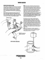
SIPHON·BREAK
For installations where the exhaust manifold/water injected exhaust elbow is close to
or will be below the vessel's waterline, provisions must be made to install a siphonbreak in the raw water supply hose to the exhaust elbow. This hose must be looped a
minimum of 20" above the vessel's waterline. Failure to use a siphon-break· when
the exhaust manifold injection porl is at or below the load waterline will result in
raw water damage to the engine and possible flooding of the boat.
If you have any doubt about the position of the water-injected exhaust elbow relative
to the vessel's waterline under the vessel's various operating conditions, install a
siphon-break.
NOTE: A siphon-break requires periodic inspection and cleaning to ensure proper
operation. Failure to properly maintain a siphon-break can· result in catastrophic
engine damage. Consult the siphon-break manufacturer for proper maintenance.
EXHAUST SYSTEM
The exhaust hose must be certified for marine use. The system must be designed to
prevent water from entering the exhaust under any sea conditions and at any angle
of the vessels hull.
Adetailed Marine Installation Manual covering gasoline and diesel,
engine and generators is supplied with each unit. Apdf copy is
available to download from our website at www_westerbeke.com.
-...v"
WESTERBEKE
Engines & Generators
iv
AVAIlABLE FROM
YOUR WESTERBEKE
DEALER
TABLE OF CONTENTS
Parts Identification ...........................,..............................2
Introduction ..................................................................,... .3
Fuel, Engine Oil and Engine Coolant... ........................ .5
Preparations for Initial Start·Up' ...................................6
Digital Control Panel .......................................................7
LCD Sequence ................................................. ,......... 7A
Digital Control Box ................................................... 7B
Remote Stop/Start Panel .................................................8
Generator Break·ln Procedure .......................................9
------------DailrRoutine ...: ...................:........-.~.~-.=.;;;.;.; ................... 9,Maintenance Schedule (Chart) .................................... 10
Fuel System ..................................................................... 12 '
Cooling System ............................................................... 13
,
Raw Water Intake Strainer ......................................... 13
Draining the Raw Water System ................................ 14
Fresh Water Cooling Circuit ...................................... 14
Changing the Coolan!... ....................................... ,...... 14
Thermosta!... ..................................................... ,......... 15
Raw Water Cooling Circuit.. .... ;................................. 16
Heat Exchanger .......................................................... 16
Raw Water Pump ........................................................ 16
Engine Lubrication 0i1 ................................................... 17
Engine Oil Change ..................................................... 17
Remote Oil Filter (Optional) ...................................... 18Starter Motor ............................ ,...................................... 19
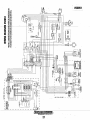
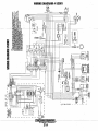
Wiring Diagrams .............................................................21
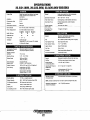
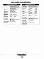
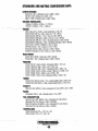
Specifications (Engines) .............................................. .22
33.0 Kw Generator .................................................. 22A
28125 Kw Generator ................................................ 22B
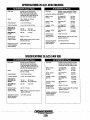
Engine Troubleshooting (Chart) ...................................23
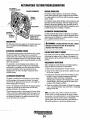
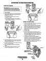
Alternator Testing ............................:................ ,............24
Battery Care ............................................................... 26
Glow Plugs .......................................................................27
Engine Adjustments .......................................................28
Valve Adjustment ....................................................... 28
01 Pressure ................................................................. 28
Engine Compression t ............................................... .28
Drive Belt Adjustment ............................................... 29
Fuel Injectors .............................................................. 29
Magnetic Pick-Up ..................................................... .30
Generator Information ...................................................31
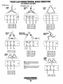
Twelve Lead Winding Connections ............................ .32
Changing Hertz and Voltage ........................................ .33
Electronic Regulation ....................................................34
Internal Wiring Oiagram ............................................... .36
Shore Power Transfer Switch .......................................37
Lay·Up and Recommissioning :......:.............................. 38
Metric Conversion Data (Chart) .................................. .40
Water Heater Connections (Optional) ........................ .41
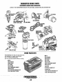
Suggested Spares ....................................................... .42
Engines & Generators
1
L
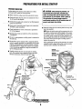
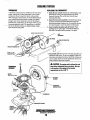
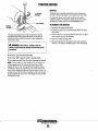
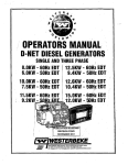
PARTS IDENTIFICATION
OIL FILL
THERMOSTAT,
CONNECTION FOR
SIPHON
AIR INTAKE/AIR FILTER •
PREHEAT SOLENOID-____ ,,~
DIGITAL CONTROL
PANEL
'
'---INJIECTlllN PUMP
dllL--.-cRIIW I~ATIER PUMP'
o._-'"LDRAIN HOSE
DC
REAR
RIGHT SIDE
FUEL LIFT
CONTROL
ANODE
HEAT
AIR INTAKE 51L1:NGI:R~P.'i-""
AIR BLEED PETI;OCIG2..
SYPHON BREAK
CONNECTION
DRIVE
COVER
. . DC ALTEIINATCIR"""--
,,-,.,rdRTOR
LEFT
SIDE
FRONT
FLEXIBLE ISOLATED
MOUNTS
~
WESTERBEKE
Eng~~.es. & GelJfJ.rstors
.
2'
MOTOR
INTRODUCTION
PRODUCT SOFTWARE
This WESTERBEKE Diesel Generator is a product of
WES1ERBEKE's long years of experid;ce and advanced
technology. We take great pride in the superior durability and
dependable performance of our engines and generators.
Thank you for selecting WES1ERBEKE.
In order to get the full use and benefit from your generator,
it is important that you operate and maintain it correctly.
This manual is designed to help you do this. Please read this.
manual carefully and observe all the safety precautions
throughout. Should your engine require servicing, contact
Product software, (technical data, parts lists, manuals,
brochures and catalogs), provided from Sources other than
WES1ERBEKE are not within WESTERBEKE's oontrol.
WESTE8BEKE CANNOT BE RESPONSIBLE FOR THE
CONTENT OF SUCH SOFTWARE, MAKES NO WARRANTlES OR REPRESENTATIONS WITH RESPECT
THERETO, INCLUDING ACCURACY, TIMELINESS OR
COMPLETENESS THEREOF AND WIU IN NO EVENT
BE LIABLE FOR ANY TYPE OF DAMAGE OR INJURY
--'-your-nearest-WES'I'ERBEKE-dealel~f0r-assistanGe"".------INefJRREf)-IN-eeNNEG'FIQN-WFFH-fJR-ARI8INGOfJ1'
This is your operators manual. A parts catalog is also
OF THE FURNISHING OR USE OF SUCH SOFTWARE.
provided and a technical manual is available from your
WES1ERBEKE dealer. If you are planning to install this
equipment, contact your WESTERBEKE dealer for
WES1ERBEKE'S installation manual.
WESTERBEKE customers should keep in mind the time
span between printings of WESTERBEKE product software
and the unavoidable existence of earlier WESTERBEKE
produci ioftware. The product software 'provided with
WESTERBEKE products, whether from WES1ERBEKE or
other suppliers, must not and cannot be relied upon exclu,".
sively as the definitive authority on the respective product. It
not only makes good sense but is imperative that appropriate
representatives ofWESTERBEKE or the supplier in question
be consulted to determine the accuracy and currentness of the
product software being consulted by the customer.
WARRANTY PROCEDURES
Your WESTERBEKE Warranty is included in a separate
folder. If, after 60 days of submitting the Warranty Registry
form you have not received a customer identification card
registering your warranty, please contact the factory inwriting with model information, including the unit's
serial number and commission date.
PROTECTING YOUR INVESTMENT.
Customer Identification Card
Care at the factory during assembly and thorough testing
have resUited in a WESTERBEKE generator capable of
many wousands of hours of dependable service. However the
manufacturer carmot control how or where the generator is
installedin the vessel or the marmer in which the unit is
operaM and serviced in the field. This is up to the
buyer/owner-operator.
,
,.~IWESTERBEKE
Custcmer Identification
MR. GENERATOR OWNER
MAIN STREET
HOMETOWN, USA
Ser. #
Model
Expires
NOTE: SiX important steps to ensure long generator life:
• Proper engine and generator installation and alignment.
• An efficient weu..designed exhaust system that includes
an anti'siphon break to prevent water from entering the
engine.
• Changing the engine oil and oil filters. accoriiini' to tke.
maintenance schedule.
NOTES, CAUTIONS AND WARNINGS
-
As this manual takes you through the operating procedures,
maintenance schedules, and troubleshooting of your maline
engine, critical information will be highlighted by NOTES,
CAUTIPNS, and WARNINGS. An explanation follows:
.
-
-
--,-~
.=,,-~~I
• Proper maintenance of all engine and generator componentsaccording to the maintenance schedule in this
manulll.
. NOTE: An operating procedure essenJial to note.
,",'
• Use clean, filtered unleaded fuel
• Winterize your engine according to the "lAy-up and
Recommissioning" section in this manual.
A CAUTION: Procedures which, if not strictly
observed, can result in the damage or destruction of
your engine.
A WARNING: Procedures Which, if not properly
followed, can result In personal injury or loss of life.
-..v: WESTERBEKE
Engines & Generators
3
INTRODUCTION
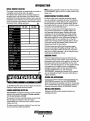
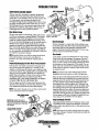
SERIAL NUMBER LOCATION
NOTE: A carbon monoxide warning decal has been provided
The engine's model number and serial number are located on
a nameplate mounted on the side of the engine.
The engine's serial number can also be found stamped into
the engine block on the flat surface of the block just above
and inboard of the injection pump. Take the time to enter this
infonnation on the illustration of the nameplate shown below,
as this will provide a quick reference when seeking technical
infonnation and/or ordering repair parts.
by WESTERBEKE. Affix this decal in a visible position in the
engine room.
UNDERSTANDING THE DIESEL ENGINE
The diesel engine closely resembles the gasoline engine,
since the mechanism is essentially the same. The cylinders
itte arranged above a closed crankcase; the crankshaft is of
the same general type as that of a gasoline engine; and the
diesel engine has the same
of valves, camshaft, pistons,
Therefore, to a great extent, a diesel engine requires the
same preventive maintenance as a gasoline engine. The
most important factors are proper ventilation and proper
maintenance of the fuel, lubricating and cooling systems.
Replacement of fuel and lubricating filter elements at the
time periods specified is a must, and frequent checking for
contarirination (that is, water, sediment, etc.) in the fuel
system is also essential. Another important factor is the use
of the same brand of high detergent diesel lubrication oil
designed specifically for diesel engines.
The diesel engine does differ from the gasoline engine,
however, in its method of handling and firing of fuel. The
carburetor and ignition systems are done away with and in
their place is a single component- the fuel injection pumpwhich performs the function of both.
ORDERING PARTS
Whenever replacement/service parts are needed, always
provide the generator model number, engine serial number,
and generator serial number as they appear on the silver and
black name plate located on the generator end. You must
provide us with this infonnation so we may properly identify
your generator set. In addition, include a complete part
description and part number for each part needed (see the
separately furrtished Parts List). Also insist upon
WESTERBEKE packaged parts because will fit or generic
parts are frequently not made to the same specifications as
original eqnipment
SPARES AND ACCESSORIES
Certain spares will be needed to support and maintain your
WESTERBEKE generator. Your local WESTERBEKE
dealer will assist you in preparing an inventory of spare parts.
See the SPARE PARTS page in this manual. For Engine and
Generator Accessories, see the ACCESSORIES brochure.
An identification plate on the top of the engine air intake also
displays the engine model and serial number.
INSTALLATION MANUAL
CARBON MONOXIDE DETECTOR
Publication #43400 provides detailed information for
installing generators.
WESTERBEKE recommends mounting a carbon monoxide
detector in the vessels living quarters. Carbon monoxide,
even in small amounts, is deadly.
The presence of carbon monoxide indicates an exhaust leak
from the engine or generator or from the exhaust
elbow/exhaust hose, or the fumes from a nearby vessel are
entering your boat.
If carbon monoxide is present, ventilate the area with clean
air and correct the problem hnmediately!
...v'
WESTERBEKE
Engines & Generators
4
DIESEL FUEL, ENGINE OIL AND ENGINE COOLANT
DIESEL FUEL
ENGINE COOLANT
WESTERBEKE recommends a mixture of 50% antifreeze
Use a diesel fuel that meets the requirements of No. 2-D
and 50% distilled water. Distilled water is free from the
SAE J 313 and has a Cetane rating of #45 or higher grade of
chemicals that can corrode internal engine surfaces.
diesel fuel according to ASTM 0975
The antifreeze performs double duty. It allows the engine to
Care Of The Fuel Supply
run at proper temperatures by transferring heat away from
Use only clean diesel fuel! The clearance of the components
the engine to the coolant, and lubricates and protects the
in your engines fuel injection pump is very critical; invisible
cooling circuit from rust and corrosion. Look for a good
c;d:;:irc>t"::p:-;ffi,"ti,, clc;ces=w;;;h;;;-ic-;,h-;;cllU;;;'-;";"g;;cht;-,p,"as=s"th,-;roo.;U:f;g,-h:;;t;;;he~pn;;;-·m=ary~a",n~d,.s.,-;ecc--_ _---"g..
ual~il)' antifreeze that contains Supplemental Cooling
ondary filters can damage these finely machmed pms. It IS
Additives (SCAs) that keep the antifreeze chemically
impOltant to buy clean fuel, and keep it clean. The best fuel
balanced, crucial to long term protection.
The distilled water and antifreeze should be premixed before
can be rendered unsatisfactory by careless handling or
improper storage facilities. To ensure that the fuel going into
being poured into the cooling circuit.
the tank for your engine's daily use is clean and pure, the
following practice is advisable:
NOTE: Lookfor the new environmentallyjriendly long lasting
Purchase a well-known brand of fuel. The use of additives
antifreeze that is now available.
to combat BACTERIAL growth in the fuel tank is
PURCHASING ANTIFREEZE
recommended such as Bio-Bar and an additive such as
Diesel Kleen + Centane Boost to help restore lubricity back
Rather than preparing the mixture, WESTERBEKE
into the diesel fuel when an Ultra Low Sulfur diesel is being
recommends buying the premixed antifreeze so that so that
when adding coolant the mixture will always be correct.
used.
There are two common types of antifreeze, Ethylene Glycol
Install and regulffi'ly service a good, visual-type fuel
(green) and Propylene Glycol (red/purple), either can be used
filter/water separator between the fuel tank and the engine.
do not mix the two and if changing from one to another,
but
The Raycor 500 MA or 230 RMAM are good examples of
flush the engine thoroughly.
such filters. A 10 micron filter element is recommended.
Premixed antifreeze for DIESEL Engines:
ENGINE OIL
Specification #ASTM D53456.
Use a heavy duty diesel oil with an API classification of CF,
MAINTENANCE
CG-4, CH-4 or CIA. Change the engine oil and filter after an
initial 50 bours of break-in operation.Then follow the oil and
Change the engine coolant every five years regardless of the
filter change intervals as specified in the MAINTENANCE
number of operating hours as the chemical additives that
SCHEDULE in this manual. Westerbeke Corporation does
protect and lubricate the engine have a limited iife.
not approve or disapprove the use of synthetic oils. If
COOLANT RECOVERY TANK
synthetic oils are used, engine break-in must be performed
using conventional oil. Oil change intervals must be as listed
The coolant recovery tank allows for the expansion and
in the MAINTENANCE SCHEDULE section of this
contraction of the engines coolant during engine operation
manual and not be extended if synthetic oils are used.
without introducing air into the system. This recovery tank is
provided with fresh water cooled models and with the fresh
NOTE: The information above supersedes all previous
water coolant conversion kit and must be installed before
statements regarding synthetic oil.
operating the engine.
SAE OIL VISCOSITY GRADE
For all temperature ranges: SAE 15W -40 or SAE 1OW-40.
~ng;n~s & Gene~ators
5
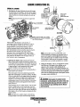
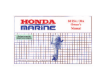
PREPARATIONS FOR INITIAL START-UP
PRESTART INSPECTION
A CAUTION:
When starting the generator, it is
recommended that al/ AC loads, especially large.
motors, be switched OFF until the engine has come
up to speed and, in cold climates, starts to warm up.
This precaution will prevent damage caused by
unanticipated operation of the AC machinery and will
prevent a cold engine from stalling.
Before starting your generator for the first time or after a
prolonged layoff, check the following items:
• Make certain the cooling water thru-hnll petcock is open.
• Check the engine oil level: add oil to maintain the level at
the full mark on the dipstick.
• Check the fuel snpply and examine the fuel filter/separator
_ _bo:wls-±bLContarninants,~._ _ _ __
• Check the DC electrical system. Inspect wire connections
and battery cable connections.
• Check the coolant level in both the plastic recovery tank
and at the martifold.
NOTE: After the initial running of the generator, the air in
the engine's cooling system will be purged to the coolant
recovery tank. Open the air bleed petcock to ensure tlult
the cooling system is purged of air. After shutdown and
after the engine has cooled, the coolant from the recovery
tank will be drawn into the engine ~ cooling system to
replace the purged air.
Before subsequent operation of the generator, the engine ~
manifold should be topped off, and the coolant recovery
tank may need to be filled!o the MAX level.
• Check load leads for correct connections as specified in
the wiring diagrams.
• Examine the air inlet and outlet for air flow obstructions
(Soundguard).
• Be sure no other generator or utility power is connected to
the load lines.
• Be Sure that in power systems with a neutral line that the
neutral is properly grounded (or ungrounded) as the system
requires, and that generator neutral is properly connected
to the load neutral. In single phase systems an incomplete
or open neutral can supply the wrong line-to-neutral voltage on unbalanced loads.
COOLANT
__
.. -JJ/
_r ._
.
~I
~
J
.•
,
'
.RECOVERYTANK
.
• Visually exartriue the uuit. Look for loose or missing
parts, disconnected wires, unattached hoses, and check
threaded connections. Search for anY(fueIl ieaks.. ~ .
OIL FILL
II
OIL FILTER'
V~~~t~~i~sZ:~~
OIL FILL
h
ABOVE
CO'OLAN, EXPANSION
6
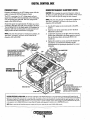
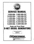
DIGITAL CONTROL PANEL
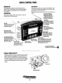
DESCRIPTION
LCD DISPLAY
WESTERBEKE'E Digital Control Panel provides the
operator with an LCD display that contunuously monitors
all the operations of the generator in easy to understand
text messages.
Operating temperatures may cause the LCD display to vary
in color. This is normal and a change in color will not affect
the operation on the ,ontrol panel.
Periodically clean the control panel LCD screen using a soft
cloth.
CONTROL BOX
UP AND DOWN ARROWS
WHEN THE LCD DISPLAY IS
IN ITS SCROLL MODE, THE
UP AND DOWN ARROWS CAN
BE USED TO ADJUST THE
Note that the design and size of the control box will vary
depending on the model generator.
-------------
---------
UP·ARROW
WHEN IN SCROLL LOCK MODE
INDIVIDUAL FUNCTIONS CAN
BE MONITORED BY PRESSING
THE UP-ARROW.
8A FUSE
PROTECTS THE CONTROL PANEL
ELECTRONICS FROM A HIGH
AMPERAGE OVERLOAD.
SCROLL LOCK
STOPS RUN SEQUENCE SO, .
THAT A SINGLEFUNCTIOirCAN
. BE MONITORED
INDICATOR LIGHTS
SIX LIGHTS THAT INDICATE
WHERE AFAULT HAS OCCURED.
. WHEN IN SCROLL LOCK MODE
INDIVIDUAL FUNCTIONS CAN
BE MONITORED BY PRESSING
THE DOWN-ARROW.
~
20A BREAKER SWITCH "SHUT-OFF WHEN PERFORMING
MAINTENANCE OR WHEN
. REPAIRING A FAUL.T. RESET TO
RESTART THE ENGINE.
FAilURE LIGHT
A RED LIGHT WILL APPEAR IF
THE RUN SEQUENCE IS
INTERUPTED BY A FAILURE.
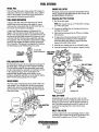
PRIME BUTTON
TillS BUriON ENERGIZES THE FUEi PUMP.
USE IT TO PURGE THE FUEL SYSTEM OF
AIR AFTER PERFORMENG REPAIRS TO THE
ENGENE'S FUEL SYSTEM OR SERVICENG
THE ON ENGENE FULE FILTERS.
START BUTTON
STARTS THE ENGINE
LCD DISPLAY SEQUENCE
...
IS SHOWN ON THE FOLLOWENG PAGE., .
*MANUAL ENGINE SHUT·OFF
Should the stop button fail in its normal function to stop the
engine. The engine is equipped with a manual shut down
lever located on the engiue block to the left of the side oil
fill. Simply hold down the lever to the left until the engine
comes to a complete stop. This shut down lever is standard
on current D-net generators and can be added to earlier
models.
SIDE OIL FILL
SHUT-DOWN LEVER
Engines & Generators
7
DIGITAL CONTROL PANEL/LCD SEQUENCE
,
,
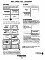
START SEQUENCE
STOP SEQUENCE
With the pre,start inspection completed, press the START
button and the automatic sequence will begin. The six
. dicator rIghts WI'11 illurruna
. te gre~n and the paneI'll
WI
m
display the following text:
To stop the generator, press the STOP button. The display
will cycle thruthe following text messages and shutdown .
Shutting'
'Cown "
'Waitlng'for operator
IWlWESTERBEKE
Press start to
----engage-generator
, Engines & Generators
FAILURE LlGHT/SHUTDOWN
If a problem occurs, the generator will shutdown and the
FAlLURE light will illuminate red. In addition, one of the
indicator lights will change from green to orange to reveal
where the trouble has occured and the display will text
message what has happened_
Examples:
,..-------~
High Engine Temp.
Failu," Light is red.
OlqU;nt Temperature Light
Reset ECU to Restart'
is orange.
As the display cycles thru the engine functions, the speed
will come up to 1800 rpms-60Hz (1500 rpms,50Hz) and
the oil pressure and engine coolanj will rise to their normal
readings. The functions will cycle in the following sequemce:
,
'Engine Speed
Co.,lani Temperaiure
'
'
180Q RPM
81C
32' .
250J-
... _-
..... -
Battery Voltage
3.1
13.5 VDC
,0
30
0
Oil Pressure
,-
i
,B.9.
0
60,1 Hz
'
--
AC Phase Voltage
100
SCROLL
At LIne Voltage
20k
~
120V0
SCROLL
_AC Phase Voltage, '"
-, - .... -8 --- . --~
lG AB3BOV
~
'"
,
0 "
Cl.
600
I
eoo.
I
"
600
!.
-"SCROLL
2~iO
SC~OI:.I:_
-. _-:..,AC"', Line
'... 8 Voltage
- :-.. . '600
AB3BOV.
'
.
,0',.
.BC 37BV ,_
C;A3BOV,
I
.,--
,
,
When a failure occurs, refer to the' troubleshooting chart;
wiring diagram, and general operating text in this manual to
assist in solving the trOUble.
There are many combinations of messages that can be
displayed but they are all self explanatory and the operator
can easily isolate and correct the problem should one occur.
Before re-starting the generator, !lie 20 amp DC circuit
breaker must be reset. With the problem corrected and the
generator started, the sequences will begin cycling again.
I
SC~Oll
Low Oil Pressure
Oil Pressure Light is or~nge, Reset ECU to Restart
..
SCROLL
' AC Frequency
3.8 HOURS
~ BC37BV,
~ CA3BO.vi
Failu," Light is red.
PSI'
19.t!
0
Engine Hours
m
4()
-
_§.~RPLL
.
0
10~
SCROLL
'B~R'
I
A120V O
'B120V
17SF
.
300'
0
SQJ~9LL
-
,
Cranking ......
...
0
,----
Waiting for operator
Press- start to
engage generator
Pre l'Ieating ......
7 Seconds
RUN SEQUENCE
-
Engine Shutdown
. '600
I
.:;.-. .600
I
. "lOCK
::r~
m
im
¢
NOTE: Three phase voltages will vary depending on the AC
output configuration of the generator.
,
,
SCROLL L O C K '
To stop the continuing sequence, press the SCROLL LOCK
button. This enables the operator to monitor a single function
for any length of time. The word LOCK will appear in the
corn~r. Use the up and down arrows 'to find and observe other
functions. To resume scrolling, press the SCROLL LOCK
button again.
'
Controt Box Components
and Frequency Adjustments
are on the following page . .-
Engines & Generators
7A
t
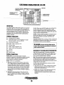
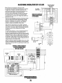
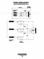
DIGITAL CONTROL BOX
FREQUENCY FAULT
GENERATOR FREQUENCY ADJUSTMENT (HERTZ)
Frequency is displayed on the LCD display screen while the
CAUTION: When changing the generator frequency setting on
engine is running in ·RPM'and!'requency (hertz).
the ECU, tum off the 20 amp DC circuit breaker· on the control
The BCU is receiving a low AC voltage signal and hertz
box. Tum it back on after the setting has been changed
signal from the MPU which is positioned on the bellhousing
over the flywheel ring gear teeth. The BCU interprets this
NOTE: If the unit shuts down for an underspeed condition, the
signal as both RPM and hertz.
same fault "overspeed" will show on the screen but the
Should this signal vary approximately 2%· either up or down,
frequency LED will BUNK.
afreguency fault shut down will occur, initiatedb~ the BCU-=-.___ .__l._Ttl~_the_DCbreakeLon_the_controLpaneLtp_the·OFF .
The red failure LED on the display panel will illuminate, the
position.
frequency LBD will tum from green to amber and the LCD
display screen will show the fault text "overspeed".
2, Open the cover of the control box and view the BCU
(Electronic Control Unit).
3. Locate the #1 dipswitch on the BCU and move it to the
NOTE: If the unit shuts down for an underspeed condition, the
position that correspontis to the Hertz operation desired).
same fault "overspeed" will show on the screen but the
See the illustration below showing the BCU in the
frequency LED will BUNK.
control box.
4. Replace the control box cov.er, tum the DC breaker ON
and start the unit. Monitor the frequency that the
engine/generator is operating is operating at the COlTect
frequency.
WHEN CHANGING THE GENERATORS
. FREQUENCY (50/60 HZ) SWITCH #1
01'1 THE CONTROL PANEL ECU
BOARO MUST BE SWITCHED:
.. .(}N FOR 50 HZ AND OFF FOR 60 HZ.
CONTROL BOX
INTERNAL cOMPbNi~NtS
~h.'.TPORT
DISPLAY PANEL
NOTE: DURIIVG OPERATION THE COLOR
~llr--u~~AMPDC
8 AMP .11« ""~
BREAKER
OF THE LCD DISPLAY MAY VARY.
CAUSED BY HEAT, THIS IS NORMAL
AND 1'10 CAUSE FOR CONCERN.
CAUTION (WESTERLINK or NMEA-20DO): The electronic components in the Digital Diesels draw a very small amount of amperage (milli-amps) from. the
.
generator s starting battery when th~. unit is in a static state.· This maybe as much as 50 milli-amps for the system ECU and 50 milli-amps for each displ.ay.
This can be as much as 72 amp-hours in a months time with no generator use. It is not necessary lo·be concerned with this slight amperage draw during
normal seasonal use. However; iJthe generator set is not to be used for a number of months, such as winter storage, it is best to disconnect the D~ power
to the generator with a NMEIt--200q system or shllt off the D.C breaker ,!n the generator's control box for a WESTERLINK system.
NOTE: Keep in mind that the Westerbeke generator maybe the DC power supply for the vessel:'" NMEA-2000 neTWork.
~
WESTERBEKE
Engines & Generators
78
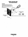
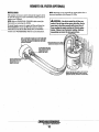
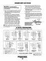
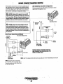
REMOTE STOP/START PANEL
AND EXTENSION HARNESSES
DESCRIPTION
A remote panel is availaple that allows the generator to be
stopped and started from any location on the boat. The
connecting harnesses come in three different lengths and two
of these can be combined for a maximum ron at 75' (22.17M).
NOTE: For additional information, contact your local
WESTERBEKE dealer.
3-1/4" (82.li5MI~),
CONNECTING EXTENSION
;6" (152.4MM)
CAOLES "
15' (4.75M)
30' (9.1M)
60' (1B.2M)
REMOTE PANELJPIG TA.ll
"_00 ~.~
PN 052959
PN 0527B9
PN 052960
Note: These two dimensions are the measurement of the cut-out opening.
~
WESTERBEKE
gnfllnes & Gene!.s!ors
S',
GENERATOR BREAK-IN PROCEDURE
DESCRIPTION
Although your engine has experienced a minimum of one
hour of test operations at the factory to make sure accurate
assembly procedures were followed and that the engine
operated properly, a break-in time is required. The service
life of your engine is dependent upon how the engine is
operated and serviced during its initial hours of use.
Breaking-in a new engine basically involves seating the
piston rings to the cylinder walls. Excessive oil consumption
~ -and-"moky-operation-indicate~that-the~C}'linder-walls~are
glazed or scored, which is caused by overloading the
engine during the break-in period.
Your new engine requires approximately 50 hours of initial
conditioning operation to break in each moving part in order
to maximize the performance and service life of the engine.
Perform this conditioning carefully, keeping in mind the
following:
Start the engine according to the STARTING PROCEDURE
section. Run the engine while checking that all systems (raw
water pump, oil pressure,. battery charging) are functioning.
AFTER START·UP
Once the generator has been started, check for proper operation and then encourage a fast warm-up. Run the generator
between 20% and 60% of full-load for the first 10 hours.
After the first 10 hours of the generator's operation, the load
can be increased to the full-load rated output, then periodically vary the load.
Avoid overload at all times. An overload is signaled by smoky
exhaust with reduced output voltage and frequency. Monitor
the current being drawn from the generator and keep it within
the generator's rating. Since the generator operates at 1800
rpm to produce 60 hertz (or at 1500 rpm tei produce 50
Hertz), control of the generator's break-in is governed by the
current drawn from the generator.
NOTE: Be aware of motor starting loads and the high current
draw required for starting motors. This starting amperage
draw can be 3 to 5 times normal running amperage. See
GENERATOR INFORMATION in this manual.
GENERATOR ADJUSTMENTS
Once the generator has been placed in operation, there may be
govemor adjustments required for engine speed (hertz) during
the engine's break-in period (first 50 hours) or after this
period see ENGINE SPEED (HER1Z) ADJUSTMENT) under
ENGINE ADJUSTMENTS.. A no-load voltage adjustment
may also be required in conjunction with the engine's speed
adjustment see GENERATOR INFORMATION.
THE DAILY ROUTINE
NOTE: Some unstable running may occur in a cold engine.
CHECKLIST
This condition should abate as normal operating temperature
is reached and loads are applied.
Follow this check list each day before starting your generator.
• Check that all generator circuit breakers (power panel) are
in the off position before starting.
A CAUTION: Do not operate the generator for long
• Record the hourmeter reading in your log (engine hours
relate to the maintenance schedule.)
periods of time without a load being placed on the
generator.
Any deficiency or problems in the following items must
be corrected before start up.
STOPPING THE GENERATOR
• Visually inspect the engine for fuel, oil, or water leaks.
Remove the AC loads from the generator one at a time.Allow
the generator to run for 3-5 minutes to stabilize the operating
temperature, then momentarily depress the stop bultOn and
release. The generator will automatically shut down. Thm off
the DC circuit breaker to prevent unintentional starts as a
safety precaution.
• Check the oil level (dipstick).
• Check the coolant level in the coolant recovery tank.
• Check your fuel supply.
• Check the starting batteries (weeldy).
• Check drive belts for wear and proper tension (weeldy).
CHECK WITH THE ENGINE RUNNING.
• Check for abnormal noise such as knocking, vibrating and
blow-back sounds.
• Confirm exhaust smoke:
When the engine is cold - White Smoke.
When the engine is wann - almost Smokeless.
When the engine is overloaded - some Black Smoke.
-.,.y'
WESTERBEKE
Engines & Generators
9
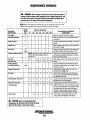
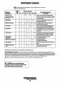
MAINTENANCE SCHEDULE
A
WARNING: Never attempt to perform any service while the engine is
running. Wear the proper safety equipment such as goggles and gloves, and
use the correct tools for each job. Disconnect the battery terminals when
servicing any of the engine's DC electrical equipment.
NOTE: Many of the following maintenance jobs are simple but others are more
-------~difficult-and-may-require-the-expert-knrjwledge-ofa-seFvice-mechanic.
SCHEOULED
MAINTENANCE
Fuel Supply
CHECK
EACH
DAY
HOURS OF OPERATION
50
100
250
500
- - - - - - -_ _ __
EXPLANATION OF SCHEDULED
MAINTENANCE
750 1000 1250
Diesel No._ 2 rating of 45 cetane or higher.
Fuel/Water Separalor
0
0
Engine Oil Level
0
Oil level should indicale between MAX. and LOW on
dipstick.
Coolanl Level
0
Check at recovery tank; if empty, check at manifold.
Add coolant if needed.
0
Inspect for proper tension (3/8" to 1/2" depression)
and adjust if needed. Check belt edges for wear.
Drive BellS
Check for water and dirt in fuel (drain/replace filter
if necessary).
weekly
Vlsuallnspeclion of Engine
0
NOTE: Please keep engine surface clean. Dirt
and oil will inhibit the engine's ability to
remain cool.
Fuel Filler
0
0
0
Inlel Fuel Filter
Starling Batteries
(and House Batteries)
0
0
0
0
Initial change at 50 hrs, then change every 250 hrs.
Replace.
Every 50 operating hours check electrolyte levels
and make sure connections are very tight. Clean off
excessive corrosion.
0
0
Generalor
0
Heal Exchanger Zinc Anode
0
FilterlWater S~parator
Engine Hoses
0
0
weekly
Engine 011 (and filter)
Exhaust System
0
0
Check for fuel, oil and water leaks. Inspect wiring
and electrical connections. Keep bolts & nuts tight.
Check for loose belt tension.
0
0
0
0
0
Initial engine oil & filter change at 50 hrs., then
change both every 250 hours.
0
0
0
0
0
0
Check that AC connections are clean and secure
with no chafing. See GENERATOR MAINTENANCE
for additional information.
0
0
0
0
0
0
Inspect zinc anode, replace if needed, clear the heat
exchanger end of zinc anode debris.
0
0
0
0
0
0
0
0
0
Chan~ the filter and/or drain water every 200 hrs,
0
0
0
0
0
Hose should be hard & tight. Replace if soft or
spongy. Check and tighten all hose clamps.
0
0
A
CAUTION: When servicing/changing DC
components, the DC power must be turned off using
either the DC breaker or the battery switch.
. . Engines & Generators
10
Initial check at 50 hrs., tben every 250 hrs. Inspect
for leaks. Check anti-siphon valve operation. Check
the exhaust elbow for carbon and/or corrosion
buildup on inside passages; clean and replace as
necessary. Check that all connections are tight.
MAINTENANCE SCHEDULE
NOTE: Use the engine hour meter gauge IXJ log your engine hours or record your
engine hours by running time. .
SCHEDULED
MAINtENANCE
Raw Water Pump
CHECK
EACH
DAY
HOURS OF OI'ERATI(jN .
50
100
250
0
0
0
At 80Q opetating hours,
disassemble and inspect
- -for-overhaUl,
-- - - - -
Coolant System
Electric Fuel lift Pump
-
0
D
0
0
"Fuellnjectol'S
0
0
0
0
0
"Starter Motor
0
0
"Preheat Circuli
0
0
"Engine Cylinder .
Compression
*/idjustlhe lialve Clearances
D
0
D
"Heat Exchanger
'Water Injected Exhaust
Elbow
EXPLANATION OF SCHEDULED
lVIAlfITENANGE
Remove the pump COver and inspect impeller;
gaSket, cam and cover fOr wear. Check the bearings
and seals (the sheft ShoulD not wobble). Lubricate
When reassembiing.
Drain, flush, and refill cooling system With the
appropriate antifreeze mix.
Periodically check the wlMng connections and
inspect the fuel line connections.
· Check and adjust injection opening pressure and
spray Condition (see EN61NE ADJUSTMENTS).
check S~eh!lld and. motor lor corrosion. Remove
and lubn ·ate. Clean and lubricate the starter motor
pinion drive.
Check operation 01 preheat solenoid. Remove and
clean gloW plugs: Check resistance (4'6 ohms).
Reinstall with antI-seize compound on threads.
· Check compression pressure and timing
(see EngIne AdjustmentS).
,
Adjust Valve Clearances
(sea ENGINE ADJUSTMENts).
· Remove, have professionally cleaned and pressure
tesled.
Check casting integrity every 500 haurs.of
operation, Replace ~ needed.
50D. 750 1000 .1250
0
0
0
..
·WESTERBEKE reCommends this servIce be performe,d by an authorized mechanic.
CAUTiON (WESTEiiUdK or NMEA·20iJO):The elelitranic components in the Digital Diesels draw a"very small amount of amperage- (milli-amps) from the
,
generator'S starling battety when. the unit i! in a static stale. TIds maybe as much liS 50 milliMamps for the system ECU and ~O milii-amps for each display. .
This can be as much its 72 amp-hours in a months time with no generator use. It is not necessary to be concerned with this am/hi amperage draw during
riofiiititsetiSiitiizfuj~'tlIiiwwdt,:::if:tht'gejjli'rdtbf:setis;iiot;td:be:·«ied:jof·'ii"iiiitiibef:;o/"moillhS;·:,suclfils·:wmtitf:stdfage;::·it;ii:;b·esft6=:mston'j""ect-:tii~·DGpoWer
to the generator With a. NMEA..2000 system qf·~h{tt· off the DC breaker on the. generator's control box/or a WESTERLINK system.
NOtE~ Keep in mind that ihe Westerbeke generator rruiybe the DC power supply jor th~ vessel's NMEA ..2000 network.
A
CAUTION: When setJlicing/changing DC
ilomponents, the DC power must be tumed off using,
either the DC breaker 01' the battery switch.
.
Engines & Genetlitors
11
FUEL SYSTEM
DIESEL FUEL
ENGINE FUEL FILTER
Use No.2 diesel fuel with a Celane rating of 45 or higher. In
conjunction with mira Low Sulphur Diesel. Use an additive
such as "Diesel Kleen" produced by Power Services PS to
help restore fuel lubrication (product #3025).
Periodically check the fuel connections and the filter bowl for
leakage. Change the filter element after the first 50 hours. See
the MAINTENANCE SCHEDULE.
Changing the Filter Cartridge
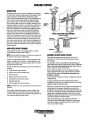
FUEL WATER SEPARATOR
1. Shut off the -fuel supply.
A primary fuel filter of the water separating type must be
NOTE: Slide a plastic bag up over the fuel filter cartridge
installed between the fuel tank and the engine to remove
as
it will be full offuel.
water and other contaminants from the fuel before they can
_he_cJlrrie~<Lto_the_fu~eLs_ystem on the engine. ____ _ ~------2.-TJnsGrew-the-cartridge-fromjts_housing_all(iremoyeJhe
cartridge and its gasket.
A typical fuel filter/water separator is illustrated in this
diagram. This is the Raycor Model 500 MA. Keep in mind
3. Wipe both the housing and the top of the new cartridge
that if a water separator type filter is not installed between the
with clean fuel.
fuel supply tank and engine-mounted fuel system, any water
4. To help reduce fuel system priming, fill the fuel filter
in the fuel will affect the fuel pump, engine filter, and injecwith diesel before installing. This will dramatically
tion equipment. The owner/operator is responsible for making
reduce the priming time needed to purge air from the
- certain the fuel reaching the engine's injection equipment is
engines fuel system before starling.
free of impurities. This process is accomplished by installing
5.
Install the new cartridge and spin on real tight by hand.
and maintaining a proper filtration/separation system.
6. Open the fuel supply. Run the engine to inspect for leaks.
TYPICAL FUEL
FILTER/WATER
SEPARATOR
10 micron filter
element recommended.
LIGHTLY WIPE
WITH CLEAN FUEL
WHEN INSTALLING
THE NEW FUEL
CARTRIDGE
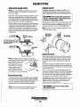
FUEL INJECTION PUMP
The fuel injection pump is the most important component of
the diesel engine, requiring the utmost caution in handling.
The fuel injection pump has been thoroughly bench-tested
and the owner-operator is cautioned not to attempt to service
it If it requires servicing, remove it and take it to an
authorized fuel injection pump service facillty. Do not
attempt to disassemble and repair it. Do not send the timing
shims with the injection pump, leave on engine.
BLEED SCREW
The bleed screW on the injection pump should be left in the
open positioIi. This will then allow for ease in priming the
engine's fuel system and during engine operation allow for
air in the system to be delivered to the fuel tank through the
fuel return system.
FUEL FILTER
CARTRIDGE
INCOMING FUEL
~~~BlEED SCREW
FUEL LIFT PUMP
FUEL INJECTION
PUMP
Periodically check the fuel connections to and out of the
pump and make sure that no leakage is present and tlmt the
fittings are tight and secure. The DC ground connection at
one ofthe pumps mounting bolts should be clean and well
secured by the mounting bolts to ensure proper pump
operations.
INLET FUEL FILTER
To ensure clean fuel into the fuel lift pump, there is a small
in-line fuel filter connected to the fuel lift pump elbow. This
filter should be replaced every 250 hours of operation.
EngJn~~ &. ~~'!.~rators
12
COOLING SYSTEM
DESCRIPTION
Westerbeke marine diesel engines are designed and equipped
for fresh water cooling. Heat produced in the engine by combustion and friction is transferred to fresh water coolant
which circulates throughout the engine. This circulating fulsh
water coolant cools the epgine block; its internal moVing
parts, and the engine oil. The heat is transferred externally
from the fresh water coolant to raw water by means of a heat
exchanger, similar in function to an automotive radiator. Raw
STRAINER
_",""Ie
·FI~TER
. CLEAN EVERY
water coolant flows around the tubes; engine heat transferred to the fresh water coolant is conducted through the
tube walls to the raw water which is then pumped into the
exhaust system where finally it is discharged overboard. In
other words, the engine is cooled by fresh water coolant, this
coolant is cooled by raw water, and the raw water carries the
transferred heat overboard through the exhaust system. The
fresh water coolant and raw water circuits are independent of
each other. Using only fresh water coolant within the engine
allows the cooling water passages to stay clean and free from
harJ)lfu1 deposits.
100 HOURS
TYPICAL RAW WATER INTAKE stRAINER.
(Owner llistalled)
INCOMING
RAW WA,I/oI"~
RAW WATER INTAKE STRAINER
A major part of the raw water cooling system is a proper
boatyard/builder installed intake strainer.
DRAINING THE RAW WATER SYSTEM
NOTE: Always install the strainer at or below the waterline so
the strainer will always be self-priming.
When freezing temperatures are expected, it is best to
protect the raw water cooling circuit and engine exhaust
from danmge.
This procedure is best accomplished by disconnecting the
water intake hose from the vessels thm-hull fitting. Close the
intake valve before disconnecting the hose. Insert the hose
end into a large container of fresh water.
Before starting the engine, remove the engine thermostat
(replace the gasket and cover). This will ensure a full flow
of water thm the engine. Re-Install the thermostat once
flusJ!ing is complete.
.
, Run the unit for 10 minutes or longer to adeq~atel y flush the
cooling system.
• Pr~vid~an ext;;mal fresh water supply for the bucket t~
maintain the water level in the bucket while the unit is being
operated during the flushing process.
A clean raw water intake strainer is a vital component of the
engine's cooling system. Include a visual inspection of this
strainer when making your periodic engine check. The water
in the glass should be clear.
Perform the following maintenance after every 100 hours of
operation:
1. Close the raw water seacock.
2. Remove and clean the strainer filter.
3. Clean the glass.
4. Replace the washer if necessary.
5. Reassemble and install the strainer.
6. Open the seacock.
7. Run the engine and check for leaks.
NOTE: Also follow the above procedure after having run hard
agroun4.
.The fresh water will flush ant the engines water passages and
, eshaust lines. If the engine is being stored and there is a
, probability of freezing, flush the engine with fresh water and
then prior to shutting the unit down substitute the fresh water
supply with a concentrated antifreeze mixture and run this
through the engine to provide freeze and corrosion protection
for both the engine and exhaust system.
When recommissioning, make certain the valves and
seacocks are open so the engine will quickly receive fresh
water. if the engine is stowed where it is warm, the fresh
water can stay in the engine.
If the engine temperature gauge ever shows a higher than
normal readiug, the cause may be that silt, leaves or grass
may have been caught up in the strainer, slowing the flow of
raw water through the cooling system.
~nglnes
& Gfmerators
13
COOLING SYSTEM
,
FRESH WATER 'COOlING CIRCUIT
CHANGING COOLANT
NOTE: Refer to the ENGINE COOLANT section for the recommended Olltijreeze and water mixture to be used as the
fresh water coolant.
Theeiigine's coolant must be changed according to 1he
MAINTENANCE SCHEDULE. If 1he coolant is allowed to
become contaminated, it can lead to overheating problems.
Fresh water coolant is pumped through 1he engine by a circuCAUTION: Proper cooling system maintenance is
lating pump, absorbing heat from 1he engine. The coolant
critical; a substantia/number of engine failures can·be
1hen passes through 1he 1hermostat into 1he manifold, to 1he
heat exchanger where it is cooled, and returned to 1he engine
traced back to cooling system corrosion.
block via 1he suction side of 1he circulating pump .
... ---Wfien 1heenginds-started-cold,externaLcoolanlflow is ~. __Dr_ain 1he engine coolant by loosening 1he drain plug on the
engine-block-and-opening.1he.manifold pressure cap. Flush
vented by 1he closed 1hermostat (although some coolant flow'
is bypassed around 1he 1hermostat to prevent the exhaust
1he system wi1h fresh water, 1hen start 1he refill process.
manifold from overheating). As 1he engine warms up, 1he
NOTE: The drain on the heat exchanger should also be us~d
1hermostat gradually opens, allowing full flow of 1he engine's
to help. drain engine coolant.
,COOlant to flow unrestricted to 1he external portion of 1he
coo1in~ s¥stem.
A
. ENGINE BLOCK
, ~. f100LANT DRAIN
KEEP THE
TO COOLANT
~ltmH~)
COOLANT pASSAGE
/1ECOVERY TANK
~
CLEAR
KEEP THESE PASSAGES CLEAR TO
A FULL FLOW OF COOLANT TO AND
THE COOLANT RECOVERY TANK ( A PIPE'
CLEANER WORKS WELL)
FROM COOLANT
RECQVERYTANK
, OIL GALLERY
..
PRESSURE
/eAP
Refilling the Coolant
After closing the engine block drain, pour clean, premixed
coolant into 1he manifold and when the coolant is visible in
1he manifold, start the engine and run it at slow idle. Open
(he air bleed petcocks on 1he manifold and 1he 1hermostat
housing.
Monitor the coolant in the manifold and add as needed. Fill
the manifold to 1he filler neck and when 1he coolant flowing
from the petcock is free of air bubbles, close 1he petcock and
install the pressure cap.
Remove the cap on the coolant recovery tank and fill with
coolant mix to halfway between LOW and MAX and replace
the cap. Run the engine and observe 1he coolant expansion
flow into the recovery tank. When 1he petcock on 1he 1hermostat housing is free of air bubbles, close iliat petcock
~re)\ecking for leaks, stop the engine and allow it to,:cool.
. Cdolaiif should draw back into 1he cooling system as the .
. engine cdols down. Add coolant to 1he recovery tank if
needed. Clean up any spilled coolant.
COOLANT RETRACTION
NOTE: Periodically check the condition of the 11ulnifold
pressU1'e cap. Ensure the upper i:md lower rubber sea~ are in
good condition. Check to ensure
.
the vacuum valve opens and
closes rightly. GaYlY a spare
cap. ChecIG also to ensure the
coolant passage is clear so
coolan.t within the, system is
able to expand and contract
to and fivm the coolant recovery tQJ'Ik
SEAL
Cooiimt Recovery Tank
,' .. ,
A coolant recovery tank allows for engine coolant expansion
and contraction during engine operation, without any significant loss of coolant and wi1hout introducing air into the cooling system. This tank should be located at or above the
engine manifold level and should be easily accessible.
A WARNING: Beware of the hot engine coolant.
NOTE: T1,;s tQJ'k, with its shOlt,.un ofplastic /wse, is best
located at or above the level of the engine's manifold.
~
Wear protective gloves.
WESTERBEKE
Engines & Generators
14
COOLING SYSTEM
THERMOSTAT
REPLACING THE THERMOSTAT
A thennostat, located near the manifold at the front of the '
engine, controls the coolant temperature as the coolant
continuously flows through the closed cooling circuit
When the engine is first started, the closed thermostat preventscoolomt from flowing (some coolant is by-passed
through a hole in the thennostat to prevent the exliaust
manifold from overheating), As the engine warms up, the
thennostat gradually opens, The thermostat is accessible
~---and-<>an-bt>-Ghecked,_cleaned_, or reglaced easily, Carry a
spare thennostat and gasket,
1. Drain off some coolant: Release the coolant pressure cap
and draio the coolant to the approximate level off the
thermostat housmg, This can be done using the heat
exchanger drain plug,
2. Rotate the thermostat assembly: Loosen the hose clamp
as shown and remove the three allen screws that hold
down the thermostat housing cover, the assembly can now
be twisted enough to access the gasket and thennostat
3.-Remol'elreplace the gasket and thermostat: When
installing the new parts, apply a thin coat ofsea:tanton
both side of the gasket before pressing it into place.
HEAT
EXCHANGER
'.CUIJUlI.,
FROM
,
~/II'O:-_ ~
'.
~e-assemble ~t:
DRAIN PLUG
Turn the cover back intopIace and
tighten the three screws, Do not over-tighten! Tighten the
hose clamp and tighten the drains, Top off the coolant and
. run the engine, Check for normal temperatnre and for any
leaks aronnd the thennostat assembly,
(
l~
THERMOSTAT
ASSEMBLY
GASKET
SEAL WITH 71-IM"~_
BLEED
PETCOCK
r,;\"'fl---AIR
HOUSING COVER
,THERMOSTAl HOUSING.
EnglQes & Generators
----15~-
COOLING SYSTEM
RAW WATER COOLING CIRCUIT'
.The raw water flow is created by a positive displacement
impeller pump. This pump draws water directly from the
ocean, lake, Of river through a hose to the water strainer. The
raw water passes from the strainer tbrough the heat
exchanger (tbrough the heat exchanger tubes) where it cools
the engine circulating fresh water coolant The raw water is
then discharged into the water injected exhaust elbow, mixing with and cooling the exhaust gasses. This mixture of
.ueJ<nausl gas arnJ-raw·water-is-pushed-0verboard.
Raw Water Pump
The raw water pump is a self-priming, rotary pump with a
non-ferrous housing and a neoprene impeller. The impeller
has flexible vanes which wipe against a curved cam plate
within the impeller housing, producing the pumping action.
On no account should this pump be run dryas water acts as a
lubricant for the impelIer. There should always be a spare
impeller and impeller cover gasket aboard (an impelIer kit).
Raw water pump impeller failures occur when lubricant (raw
water) is not present during engine operation. Such failures
are not warrantable, and operators are cautioned to make sure
raw water
flow
is present at start-up.
-.,
.....- --_..
. Heat Exchanger
; ZINC ANOmiES
The heat exchanger is a copper tube which encloses a num. ber of smalI copper tubes. Raw water is pumped through the
small copper tubes and the freshwater coolant from the
engine is circulated around the copper tubes. The raw water
removes _heat from the freshwater coolallt, __
Zinc Anode
NOTE: Should a failure occur with the pumps internal parts
Azine anode, or pencil, is located in the raw water cooling
circuit within the heat exchanger. The purpose of the zinc
"Ilode is to sacrifice ilself to electrolysis action taking place
in the raw water cooling circuit, thereby reducing the effects
of electrolysis on other components of the system. The condition of the zinc anode should be checked monthly and the
anode cleaned or replaced as required. Spare anodes should
be carried on board.
(seals and bearings), it may be more cost efficient to
purchase a new pump and rebuild the original pump as
a spare.
Inspecting/Changing the Raw Water Pump· Impeller
Close the raw water intake valve. Remove the pump cover
and, with the proper size impelIer tool, carefulIy pry the
impeller out of the pump (the impeller can be pried out using
a pair of screwdrivers if an impeller pulIer is unavailable. Take
. carenot to tear the impeller). Install the new impeller and
·gasket; Move the blades to conform to the curved carn plate
and push the impeller into the pumps housing. Whe!}
aSsembling, apply a thin coating of lubricant to the impelIer
and gasket Open the raw water intake valve..
' •..
Run the engine and check for leaks around the pump. Also
check for water discharge at the stem tube. Absence of w,\lter
flow indicates the pump has not primed itself properly.
NOTE: Electrolysis action is the result of each particular
installation and vesse/location; not that of the generator.
If the zinc pencil needs replacement, hold the hex boss into
which the zinc pencil is threaded with a wrench while loosening the anode with another wrench. This prevents the hex
boss from possibly tearing off the exchanger shell. After
removing the zinc, note the condition of it. If the zinc is in
poor condition, there are probably a lot of zinc flakes within
the exchanger. Remove the end of the heat exchanger and
clean the inside of all zinc debris. Always have a spare heat
exchanger end gasket in case the present one becomes damaged when removing the end cover. Replace the gasket (refer
to your engine model's heat exchanger end gasket part number); a-ring, cover, and install a new zinc pencil.
NOTE: Never allow the pump to run dry. [';ven a short period
of dry running may destroy the impeller.
. RAW WATER PUMP
pNS2650 .
Heat Exchanger Service
INSPECTION: CHECK THE BASE OF
•EACH BLADE BY BENDING VIGOROUSLY
REPLACE THE IMPELLER IF THERE ARE
.ANY CRACKS.
~~e~:1i:,:~~~t:~~ 1000 hours of operation, remove, clean
a
test the engine's heat exchanger. (A local auto-
:,>. ,moilive radiator shop should be able to clean and test the heat
AW""""lf",· NOTE: Operating in silty and/or tropical waters may require
th~t a heat exchanger cleaning be performed more often than
every 1000 hours.
Englne!.& Generators
16
ENGINE LUBRICATING OIL
~
ENGINE OIL CHANGE
1. Draining the oil sump. Discharge the used oil through
the sump drain hose (attached to the front of the engine)
while the engine is warm. Drain .the used oil completely,
replace the hose in its bracket and replace the end cap
securely.
NOTE: THread size for the lube oil drain hose capped end
i:; 114NFT.
APPLY GLEAN
ENGINE OIL
INSTALLING
SIDE Oil FILTER
[11/161 SOCKET
WIPE SURFACE CLEAN
BEFORE INSTALLING.
~"'<:I\'RE~!oVE USING AN BMM (11116'; SOCKET
THE OIL OR PUMP THE WARMED
UP THRU THE HOSE.
Always observe the used oil as it is removed. A
yellow/gray emulsion indicates the presence of water in
the oil. Although this condition is rare, it does require
prompt attention to prevent serious damage. Call a
qualified l)lechanic should water be present in the oil.
Raw water present in the oil can be the result of a fault in
the exhaust system attached to the engine andlor a
siphoning of raw water through the raw water cooling
circuit into the exhaust, filling the engine. This problem is
often caused by the absence of an anti-siphon valve, its
pooilocation or lack of maintenance.
2. Replacing the oilfilter. When removing the used oil
filter, you may find it helpful and cleaner to punch a hole
in the upper and lower portion of the old filter to drain the
oil from it into a container before removing it. This helps
to lessen spillage. A small automotive filter wrench
should be helpful in removing the old oil filter.
NOTE: Do not punch this hole without first loosening the filter to
make certain it can be removed.
Place some paper towels and a plastic bag around the
filter when unscrewing it to catch any oil left in the filter.
(Oil or any other fluid on the engine reduces the engine's
cooling ability. Keep your engine clean.) Inspect the old
oil filter as it is removed to make sure that the rubber
sealing gasket comes off with the old filter. If this rubber
sealing gasket remains sealed against the filter bracket,
gently remove it.
When installing the new oil filter element, wipe the filter
gasket's sealing surface on the bracket free of oil and
apply a thin coat of clean engine oil to the rubber gasket
on the new oil filter. Screw the filter onto the threaded oil
filter nipple on the oil filter bracket, and tighten the filter
finniy by hand.
1..
NOTE: THe engine oil is cooled by engine coolant flowing
through passages in the oil filter bracket musing assembly.
OIL FILL.
NOTE: Generic filters are not recommended, as the
material standards or diameters of important items on
generic parts might be entirely different from genuine
parts. Immediately after an oil filter change and oil fin
run the engine to make sure the oil pressure is nonnal
and that there are no oil leaks around the new 011 filter.
3. Fuling the Oil Sump. Add new oil through the oil filler
cap on the top of the engine, After refilling, run the
engine for a few moments while checking the oil
pressure. Make sure there is no leakage around the ne,:"
oil filter or from the oil drain system, and stop the engme.
Then check the quantity of oil with the lube oil dipstick
Fill to, but not·overthe high mark on the dipstick, should
the engine require additional oil.
A WARNING: Used engine oil contains harmful
contaminants. Avoid prolonged skin contact. Clean skin
and nails thoroughly using soap and water. Launder or
discard clothing or rags contaIning used oil. Oiscard
used oil properly.
Engines & Generators
17
REMOTE OIL FILTER (OPTIONAL)
,NSTALLATJON .
!This popular accessory is used to relocate the engine's oil illter from the engine to a more convenient location such as an
(>ngine room bulkhead.
.
~DTE: Refer to ENGINE OIL CHANGE in this manualfor
Instructions on removing the oil filter.
.
U:b install:simply remove the engine oil illter and thread on
WESTERBEKE's remote oil filter kit as shown. Always
Jnstall this kit with the oil illtel;"facing_down as ilIustrated,--Contact your WES1ERBEKE dealer for more infonnation.
NOTE: Westerbeke is not responsible jor engine failure due to
incorrect il11italllltion of the Remote Oil Filter.
A CAUTION: It is vital tofnstall the oil lines correctly. If the 011 flows in the rBvBrse direction, the bypass valvB in the filter assembly will prevent the oil
from rBachlng the englnecauslnganinternal engine _
fiiiliIijj;-ffthere Is no oil plBssnrB readliiif, shutdown.
Immediately and check the h,!!1!,g~I~ct;'[/ns.
APPLY ATHIN COAT OF CLEAN OIL TO THE O'RING WHEN
INSTALLING THiS KIT. THREAD THE KIT ON. THEN HAND
TIGHTEN AN ADDITIONAL 3/4 TURN AFTER THE O·RlNG
CONTACTS THE BASE.
THE IN CONNECTION HOSE
MUST ATTACH TO THE OUT
CONNECTION ATTHE
Je~---R'~IOTE OIL FILTER.
THE OUT CONNECTION "M'r"",~
MUST ATTACH TO THE IN
CONNECTION ATTHE
REMOTE OIL FILTER.
APPLY ATHIN COAT OF CLEAN OIL TO THE FILTER
GASKET WHEN INSTALLING. AFTER THE FILTER
CQ.NTAGTSTHE BASE. TIGHTEN IT AN AOOlTIONAL'
Engines & Generators
18
STARTER MOTOR
SOLENOID
DESCRIPTION
The starting system includes the battery, starter motor, solenoid,
and starter button.
When the starter button on the insttument panel is depressed,
current flows and energizes the starter's solenoid coil. The
energized coil becomes an electromagnet, which pulls fue plunger
IGNITION
into the coil, and closes a set of contacts which allow high current
TERMINAL
to reach the starter motor. At the same time, fue plunger also
serves to push timt starter pinion to mesh witlllhe teefu on tile
--~--f1ywlieel.
.
. ~~~~~~~~----To prevent damage to tile starter motor when fue engine starts, the
pinion gear incorporates an over-running.(one-way) clutch which
is splined to the starter armature shaft. The rotation of the running
engine may speed tile rotation of tile pinion but not the starter
motor itself.
Once the started button is released, the cummt flow ceases, stopping fue activation of tile solenoid. The plunger is pulled out of
contact with tile battery-to-start cables by a coil spring, and fue
ftow of electricity is interrupted to fue starter. This weakens the
magnetic fields and tile starter ceases its rotation. As fue solenoid
plunger is released, its movement also pulls tile stalter drive gear
from its engllgement witil tile engine ftywheel.
TERMINALS'-~-~~
,,,,,,,-,,,,·~~I(J~""""---(M) TERMINAL
In
To test tile ignition circuit, locate tile ignition(s) terminal (it is one'
of the small terminal studs and is wired to fue ignition circuit).
· Use a screwdriver, don't touch fue blade, to jUlllp from tilat
ignition terminal to tile positive battery c01lllection tennlllOl ou
· fue solenoid..
· If the starter cranks, the fault lies with the ignition circuit
If the solenoid clicks but nothing else happens, the starter
motor is probably faulty.
SOLENOID
SOLENOID
MOTOR
c:;;:;~'(:!~r}<---(+) POSITIVE
TERMINAL
TYPICAL
STARTER MOTOR
~~--'(M) TERMINAL
REFER TO THE WIRING
DIAGRAM IN THIS MANUAL
IGNITION
TERMINAL
TROUBLESHOOTING
Prior to testing, make certain the ships batteries are at full charge
and that tile starting system wiring cOlmections (telminals) are
clean and tight. Pay particular attention to tile ground wire
comlections on the engine block.
To check the wiring, try cl1l11king fue slalter for a few seconds,
never more tiJan 10 seconds at a time, tilen run your hand along
tile wires and terminals looking for warm spots timt indicate
resistance. Repair or replace any trouble spots.
USlllg a multimeter, test the voltage between tile positive terminal
stud on the stalt solenoid and the engine block (ground).
If you read 12 volts, the starter is faulty.
~
, If nothing at all bappens the solenoid isn't getting cnrrent.
, Check the battery isolation switch and inspect the wiring
. colmections. It is also possible that the solenoid is defective.
. A WARNING: There will be arching and sparks will
fly when jumping terminals. Be certain·the engine
space is feee of potentially explosive fumes, especially
gasoline.
~WESTIiRBIiKli
Engines &: Generators
19
STARTER MOTOR
SERVICE
Westerbeke uses a standard marine starter motor which can be
serviced or rebuilt at any starter motor automotive service center.
If replacing the starter motor, make cerlain fue new motor is
certified for marine use. Automotive starters do not meet USCG
standards. If in doub~ contact your WESTERBEKE dealer.
POSITIVE
~J'.1'Wrt(r""--~IM)TERMINAl
TO REMOVE FOR SERVICE
1. DiscOlmectthe negative battery cable.
2. If necessary, remove any components to gain fuJI access to fue
starter motor.
3. Label and disconnect the wiring from the starter. (Do not allow
wires to touch, tape over the terminals).
4. Remove tlle starter mounting bolts.
5. Remove the starter from tlle engine. In some cases the starter
will have to be turned to a different angle to clear obstructions.
Test again by jumping the two large terminal studs. Hold tl,e
screwdJiver blade finnly between tl,e studs. Do not allow tlle
screwdJiver blade to touch the solenoid starter casing, this
would cause a short.
0,
A WARNING: There will be arching as the full
starting current should be flowing thru the blade of the
screwdriver.
IT tbe starter spins, tbe solenoid is faulty.
IT tbe starter fails to spin, the motor is probably faulty.
IT no arching occurred. Tbere is no juice reaching tbe solenoid.
NOTE: Starter motors are either inertia type or pre-engaged. In
the pre-engaged model, the solenoid also moves an arm that
engages the starter motor to the flywheel ofthe engine. Using a
screwdriver to bypass the solelWid on such a starter will run the
motor without engaging the flywheel. Tum the starter switch on to
provide the power to the solelWid. HopefUlly it will create enough
magnetic field for the arm to move even though the contacts inside
the solenoid are bad.
-..v- W/iSTERBEKE
Er!g!nes. &- Generators
20
#52951
WIRING DIAGRAM # 53901
l
±:i:~~~~~~~~'1,-,-~~~J::;~J1~ ,
;:j::j:j::~:[)J i !!
e I
.J
I
I
_ _ _ _ _ _ _ _ _ _. _ ~WES:TE8BEKE
Engines & Generators
21A
SPECIFICATIONS
25.5/21.0KW, 28.5/23.5KW, 33.0/26.0KW EDE/EDEA
COOLING SYSTEM
GENERAL
Diesel, four-cycle, four~cylinder, fresh water-
Engine Type
Aspiration
Naturally aspirated.
Compression Ratio
21.8:1
Governor
Electric
controlled with heat exchanger.
I~Co~m~b~us~ti~on~C~hillam~b~erL-__~Sw~ir~l~p~e______~~~~~~_I
Bore & Stroke
98 x 110 mm (3.86 x 4.93 inches)
Piston Displacement
3.31 liters (202.53 cubic inches)
Hp@1800 rpm
33.0/26.0
50
25.5/21.0
39
28.5/23.5
43
Hp@1500rpm
40
32
36
Operating Temperature
160-180' F(71-82' C)
Fresh Water Pump
Centrifugal type, metal impeller, belt-driven.
Raw Water Pump
Positive displacement, rubber impeller,
gear driven
SystemCapaeity_
(fresh water)
16 USgl>:(15.Hters)/~___
Raw Water Flow
(at 1800 rpm)
11.0 gpm (41.6 gpm)
FUEL SYSTEM
General
Open flow, self bleeding, self priming
(electromagnetic fuel pump)
Continuous 20°
Temporary 30' (not to exceed 10 minutes)
Fuel
No.2 diesel oil (cetane rating of 45 or higher)
Fuel Injection Pump
Bosch type mini-pump
11351bs (514.8 kgs)
Fuel Injection Timing
11.5' - 12.5' BlDC
Injector Nozzle
Bosch !Throttle type
Firing Order
1-3-4-2
Inclination
Weight (dry)
Fresh water-cooled block, thermostatically-
General
cooled, vertical in-line overhead valve
mechanism.
TUNE-UP SPECIFICATIONS
Compression Pressure
(allowable limit)
626 psi (44 kgf/cm') at 250 rpm
472 psi (30.5 kgf/cm') at 250 rp
Variation between
Cylinders
10% or less
Injection Timing
11.5' - 12.5' BTOC
Engine Speed
1800 rpm (60Hz)
1500 rpm (50Hz)
Valve Clearance
(engine cold)
0.23 to 0.27 mm
(0.00091 - 0.D106 inches)
Injector Pressure
1991 to 2134 psi (140 to 150 kgf/cm').
Valve Timing
Intake Opens 14' BTDC
Intake Closes 36' ABDC
Fuel Filter
Spin-on type
Air Intake
Metal screenlintake silencer box
Air Row Combustion
105 cfm (3.0 cmm)
LUBRICATION SYSTEM
General
Pressure fed system with external relief valve
Oil Filter
Full flow, paper element, spin-on type.
Sump Capacity
(not including filter)
14.0 U.S. qts (13.2 liters)
Operating Oil Pressure
(engine hot)
28 - 57 psi (2.0 - 4.0 kg/cm')
Oil Grade
API Specification CF, CG-4, CI-4
SAE 10W-30 or 15W-40
Exhaust Opens 45' BBDC
Exhaust Closes 17' ATDC
GENERATOR COOLING
ELECTRICAL SYSTEM
L
0.8 Power factor unit. 500 elm (15.0 cmm)
Starting Battery
12 Volt, (-) neg"tive ground
Generator Cooling
Air requirements
Battery Capacity
800 -1 000 Cold Cranking Amps (CCA)
NOTE: Increase coolinf air flow 15% for for slower turning 50 Hz units.
DC Charging Alternator
650 Amp rated, belt-driven
Starter
2.5Kw, 12VDC direct drive
Starting Aid
Glow plugs, sheathed type
DC Cranking Current
400 - 600 (includes glow plugs)
Generator Compartment
Ambient Temperature
____________
/
~.J/
L -_ _ _ _ _ _ _ _ _ _ _ _---"
----
"",WESTERBEKE-Engines ~ Generators
221
122 ·'F (50'C) maximum
SPECIFICATIONS 33.0/26.0KW EDE/EDEA
AC GENERATOR (Single Phase)
Single Phase
._
Brushless, Six-pole, revolving field. Sealed
lubricated, single-bearing design. 12 Lead
reconnectable (Double Delta lor 120/240 volts,
60hz) (series Star lor 230 volts. 50hz) With
solid state voltage regulator.
Voltage
120 or 120/240 Volts - 60 Hertz
230 VOhs - 50 Hertz.
Voltage regulation:
±2% no load to lull load.
--~reguru:J..QY---.rngulation:
AC GENERATOR (3 Phase)
_
Rating (Volts AC)
60 Hertz (1800 rpm)
33.0KW
Three Phase
15.0 KW· 60 HERlZ
12.0 KW· 50 HERlZ
Brushless, six-pole, revolving field. Sealed
lubricated, Single-bearing design. -12 Lead
reconnectable. Solid state voltage regulator.
Voltage - 3 phase
(60 Hertz)
Low Voltage WYE
High Voltage WYE
DELTA
240 Volts
480 Volts
277 Volts
Voltage - 3 Phase
(50 Hertz)
High Voltage WYE
DELTA
400 Volts
230 Volts
LowVoltage-WYE
High Voltage WYE
DELTA
-99.3 Amps
49.6 Amps
86.0 Amps
Amperage - 3 phase
(50 Hertz)
High Voltage WYE
DELTA
46.9 Amps
81.6 Amps
Generator Cooling
Air Requirements
(60 Hertz) at 1BOO rpm
225 - 250 clm (5.66 - 6.37 cmm)
.J·Hertz (.5%t!wJ.oadto_luII-loalt ____ _ _ =8mp_erag,-3_p_base
I
(60 Hertz)
120 Volts
120/240 Volts
275 Amps
50 Hertz (1500 rpm)
26.0KW
230 Volts
113 Amps
Generator Cooling
Air Requirements
(Single and 3 Phase)
500 clm (614.1 cmm)
Generator Compartment
Arribient Temperature
Recommendations
122°F (50°C) maximum
275/137.5 Amps
operation (1500 rpm).
NOTE: Increase air supply 15% for 50 Hertz
operation (1500 rpm).
~
NOTE: Increase airsupply 15% for 50 Hertz
Generator Cooling
Air Requirements
(Single and 3 Phase)
500 cfm (614.1 cmm)
Generator Compartment
Ambient Temperature
Recommendations
122°F (50°C) maximum
WESTERBEKE
Engines & Generators
22A
SPECIFICATIONS 25.5/21.0KW EDE/EDEA
AC GENERATOR (3 Phase)
AC GENERATOR (Single Phase)
Single Phase
Brushless, six-pole, revolving field. Sealed
lubricated, single-bearing design. 12 Lead
reconnecteble. Solid state voltage regulator.
Brushless, six-pole, revolving field.
Seallubrtcated, single bearing design.
12 lead reconnectable, (Double Delta for
1201240 volts, 60hz.) (Series Star for 230
volts, 50hz) with solid state regulator.
Voltage
120 or 1201240 valls - 60 hertz
230 Volts - 50 Hertz
Voltage Regulation
± 2% no load to full load.
~r~quency
.3 Hertz (.5%) no load to full load.
Regulation
Rating (Volts AC)
60 Hz (1800 rpm)
25_5KW
Three Phase
Low Voltage WYE
High Voltage WYE
DELTA
240 Volts
4BOVoits
277 Volts
Voltage - 3 Phase
(50 Hertz)
High Voltage WYE
DELTA
400 Volts
230 Volts
Low Voltage WYE
. Hign-VOItageW1'E
DELTA
~8'Amps---
Amperage - 3 phase
(50 Hertz)
High Voltage WYE
DELTA
37.9 Amps
65.9 Amps
Generator Cooling
Air requirements
(Single & 3 phase)
400 cfm (11.3 cmm)
Generator Compartment
Ambient Temperature
Recommendations
122'f (50'C) maximum
Amperage - 3 phase
(60C Hem) .
120 volts
1201240 valls
212.5 amps
212.5/1 06.3 amps
50 Hz (1500 rpm)
21,OKW
230 valls
91.3 amps
Generator Cooling
Air requirements
(Single & 3 phase)
400 cfm (11.3 cmm)
NOTE: Increase air supply 15% for 50 Hertz
operation (1500 rpm)
Generator Compartment
Ambient Temperature
Recommendations
Voltage - 3 phase
(60 Hertz)
122'f (50'C) maximum
76 Amps
66.5 Amps
NOTE: Increase air supply 15% for 50 Hertz
operation (1500 rpm)
temperatures below 104'F (40'C)
SPECIFICATIONS 28.5/23.5KW EDE
AC GENERATOR (Single Phase)
Single Phase
AC GENERATOR (3 Phase)
Brushless, Six-pole, revolving field.
Seal lubricated, single bearing design.
12 lead reconnecteble, (Double Delta for
1201240 volts, 60hZ.) (Series Star for 230
volts, 50hz) with solid state regulator.
Voltage
120 or 1201240 valls - 60 hertz
230 Volts - 50 Hertz
Voltage Regulation
±2% no load to full load.
frequency Regulation
.3 Hertz (.5%) no load to full load.
Rating (Volts AC)
60 Hz (1800 rpm)
28_5KW
120 volts
1201240 volts
237.5 amps
237.511186.8 amps
50 Hz (1500 rpm)
23_5KW
230 volts
10~2
Generator Cooling
Air requirements
(Single & 3 phase)
400 cfm (11.3 cmm)
NOTE: Increase air supply 15% for 50 Hertz
operation (1500 rpm)
Generator Compartment
Ambient Temperature
Recommendations
-------~
amps
..
122°F (50 'C) maximum
---_
..
Three Phase
Brushless, Six-pole, revoMng field. Sealed
lubricated, single-bearing design. 12 Lead
reconnectable. Solid state voltage regulator.
Voltage - 3 phase
(60 Hertz)
Low Voltage WYE
High Voltage WYE
DELTA
240 Volts
480 Volts
277 Volts
Voltage - 3 Phase
(50 Hertz)
High Voltage WYE
DELTA
400 Volts
230 Volts
Amperage - 3 phase
(60 Hertz)
Low Voltage WYE
High Voltage WYE
DELTA
85.8 Amps
42.9 Amps
74.3 Amps
Amperage - 3 phase
(50 Hertz)
High Voltage WYE
DELTA
42.4 Amps
73.8 Amps
Generator Cooling
Air requirements
(Single & 3 phase)
400 cfm (11.3 cmm)
Generator Compartment
Ambient Temperature
Recommendations
122'f (50'C) maximum
·~WESTERBEKE~
Engines & ,Generators
·228 .
NOTE: Increase airsupply 15% for 50 Hertz
operation (1500 rpm)
ENGINE TROUBLESHOOTING
LCD DISPLAY FAUl.TS
PROBLEM
LCD DISPLAY DOES
NOT ILLUMINATE
LOW OIL PRESSURE
1.
2.
3.
4.
HIGH EXHAUST TEMPERATURE
BATTERY VOLTAGE
GENERATOR FREQUENCY
Overspeed (steady LED)
Underspeed (flashing LED)
LED OISPLAY EDGES
TURN PINK
WAITING FOR ECU
1.
2.
3.
4.
Check battery. .
20 amp breaker off.
LOose display connection.
1 amp fuse blown (faulty) ..
Battery on.
Turn breaker on.
Check all cable connections.
Check/replace. Determine cause
1. Oil levellow/oil leak.
1. Check oil level, add oil and repair leaks.
2. Lack of oil pressure
2. Test oil pressure. If OK, test oil pressure send or. inspect
_oiLfilter, insp.ectJJiLpurnp.
-- -
HIGH COOLANT TEMPERATURE
VERIFICATIONJREMEOY
PROBABLE CAUSE
-- ----
-- - - - - - - - - -
3. Ground connection.
4. Faulty control module (ECU).
3. Check ground connection.
5.
1.
2.
3.
4.
5.
6.
5. Check sensor/replace.
1. Add coolant. Check for leaks.
2. Inspect impeller/pump/replace.
3. Adjust belt tension, replace belt.
4. Check sensor/replace.
5. Check ground circuit.
6. Check plug connections/replace.
4. Inspect all the plug connections/replace.
Faulty oil pressure sensor.
Check system coolant level.
Seawater pump.
Check water pump drive belt.
Faulty temperature sensor.
Ground connection.
Faulty control module (ECU).
1. Check sea water flow.
1. Inspect thru hull fitting. hose and strainer. Correct
as needed.
2.
3.
4.
5.
6.
1.
2.
3.
4.
1.
2.
3.
4.
2.
3.
4.
5.
6.
1.
2.
3.
4.
1.
2.
3.
4.
1.
2.
3.
4.
5.
1. Ventilate compartment.
Note: Heat wil/ often change the c%r of an LCD
display. This will not effect the operation of the engine.
1. Check compatibility with Westerlink or NMEA.
2. Check all cable connections.
3. Turn ON, check DC voltage across breaker.
4. Check/replace fuse. Check DC voltage across fuseholder
5. Check all terminating resistors are in place. 120 ohm
per resister measured across pin #4 and #5.
6. Check between pins P2-24 and P2-25. P2 ECU pluQ
unplugged from ECU. Power turned nN. If voltage IS
present, ECU is faulty.
Faulty exhaust temperature switch.
Ground Connection.
Faulty control module (ECU).
Sea water pump.
Faulty fire suppression system.
Check alternator drive belt.
Check charge voltage.
Check battery connections.
Faulty control module (ECU).
Check engine speed.
Check fuel supply.
Amperage load.
Crank cycle with no start.
(underspeed fault)
1. Compartment ambient temperature
too high.
ECU and LCD display not compatible
Loose cable connection.
Panel DC breaker OFF.
Blown 8 amp fuse.
Terminating Resistors.
6. Battllry Voltage to ECU.
Test/replace.
Check ground circuit.
Check plug connections.
InspeC:! impeller/replace.
By-pass system/check.
Adjusttenslon/replace if worn.
Check excitation. Replace/repair alternator
Check + and - cables froin battery to engine.
Check plug connections/replace.
Check speed setting.
Inspect filters/replace filters. Test fuel pump operation.
Check + and - cables from battery to engine.
Check cause for no start.
Engines & Generators
23
ALTERNATORS TESTING/TROUBLESHOOTING
VOLTAGE REGUlATOR
60 AMP ALTERNATOR
The integral voltage regulator is an electronic switching
device which senses the system voltage level and switches
the voltage applied to the field in order to maintain a proper
system voltage.
The regulator design utilizes all-silicon semi conductors and
thick-film assembly
After the voltage has been
adjusted to the proper
valve, the entire circuit is
possible damage due to handling or vibration.
t16 VIOLET R
TO K:3 RELAY
#16 RED TO
ACTUATOR "
ALTERNATOR TROUBLESHOOTING
REFER TO THE WIRING
DIAGRAM IN THIS
MANUAL FOR ALL
WIRING CONNECTIONS
DESCRIPTION
The following information applies to the staJ)dard altemator~
that are supplied with WESTERBEKE'S Engines and
Generators.
ELECTRICAL CHARGING CIRCUIT
The charging system consists of an alternator with a voltage
regulator, an engine DC wiring hamess, a mounted DC
circuit breaker and a battery with connecting cables. Because
of the use of integrated circuits (IC's), the electronic voltage
regulator is very compact and is mounted internally or on the
back of the alternator.
It is desirable to test the charging system (alternator and
voltage regulator) using the wiring hamess and electrical
loads that are a permanent part of the system and will then
provide the tecbuician with an operational test of the
charging system as well as the rnajor components of the
elec!l;ical system.
.
ALTERNATOR DESCRIPTION
,The stator is con~ectecito a three-phase, full-wave bridge
rectifier package which contains six diodes. The bridge '
converts the AC generated in the stator to a DC output for
battery charging and accessories,
Power to the regulator and the field of the integral regulator
alternator is provided by the field diode (or diode trio)
package contained in the alternator.
These alternators produce a rated output of 60 amps. Rated
output is achieved at approximately 6000 alternator rpm at
an ambient temperature of 75'F (23.8'q. The alternators
are desigued to operate in an ambient temperature range
of _40' to 212'F (_40' to 100'C).
Use this troubleshooting section to determine if a problem
exists with the charging circuit or with the alternator. If it is
determined that the alternator or voltage regulator is faulty,
have a qualified tecbuician check it.
A WARNING: A working alternator runs hot. A failed
alternator can become very hot. Do not touch the
alternator until if has cooled.
LOW BATTERY/FAULTY CIRCUIT
If the starter only moans or makes a clicking sound instead
of spinning the engine to life it is likely a low battery or a
faulty connection in the starting circuit and not an alternator
problem.
PRELIMINARY INSPECTION
Before starting the actual alternator and voltage regulator,
testing the following checks are recommended.
1. Make certain your alternator is securely mounted.
2. Check the drive belts for proper tension. Replace the belt
if it is worn or glazed.
3. Check that all terminals, connectors and plugs are clean
'and tight. Loose or corroded connections cause high
resistaoce and this could cause overcharging,
unde)'charging or damage to the charging system. Badly
corroded battery cables could prevent the ba~ from
reaching a fully charged condition.
4. Check the condition of the battery and charge if necessary.
A low or discharged battery may cause false or misleading
readings in the tests.
NOTE: An isolator with a diode, a solenoid, Qr a battery
selector switch is usually mounted in the circuit to isolate
the batteries so the starting battery is not discharged along
with the house batteries. If the isolator is charging the
starting battery but not the house battery, the alternator is
OK and the problem is in the battery charging circuit.
Engines &. Generators
24
ALTERNATORS TESTING/TROUBLESHOOTING
MEASURING
BATTERY VOLTAGE
TESTING THE ALTERNATOR
(IGNITION ON
ENGINE OFF)
A CAUTION: Before starting the engine make
certain that everyone is clear of moving parts! Keep
away from sheaves and belts during test procedures.
1. Start the Engine.
----2;-After!lie enginelias
few mm:';;;;ui;;teO;-s,~m~e;;o~:;;;su;;;rO;-~"th;;;e~~~-~~cc=
starting battery voltage at the battery termin'lis using a
multimeter set on DC volts.
a.Ifthe voltage is increasing toward 14 volts, the
alternator is working.
b.If the voltage remains arouud 12 volts, a problem
exists with either the alternator or the charging circuit;
continue with Steps 3 through 61.
run fora
TESTING THE OUTPUT CIRCUIT
MEASURING
BATTERY VOLTAGE
1. Connect the positive probe to the output terruinal B and
connect the negative probe to ground.
(ENGINE RUNNING)
2. Wiggle the engine wiring harness while observing the
voltmeter. The meter should indicate the approximate
battery voltage, and should not vary. If no reading is
obtained, or if the reading varies, check the alternator
output circuit for loose or dirty connections or
darnaged wiring.
3. Start the engine.
4. Repeat the same measurement, the negative probe to
ground, the positive probe to B with the engine runuing.
The voltage reading should be between 13.5 and 14.5
volts. If your alternator is over or under-charging, have
it repaired at a reliable service shop.
S. If the previous test reads only battery voltage at
terruinal B, use the meter to measure the DC excitation
terruinal. If 12 volts is not present at exciter terminal R,
inspect the wiring for break& and poor connections.
Jump 12 volts from a 12 volt source (such as the
battery) and operate the alternator. If the voltage output
is 13-14 volts, .. then the alteruator is OK.
3. Thrn off the engine. Inspect all wiring and connections.
Ensure that the battery tenninals and the engine ground
connections are tight and clean
4. If a battery selector switch is in the charging circuit,ensure
that it is on the correct setting.
S. Thrn on the ignition switch, but do not start the
engine.
6. Check the battery voltage. If your battery is in good
condition the reading should be 12 to 13 volts.
/ TERIWINAL R
TESTING THE OUTPUT
CIRCUIT ENGINE RUNNING
#10 ORANGE B
TO STARTER 'UL.tNUIU
,Engines ~ Generators
25
#16 VIOLETR
TO KolRELAY
#16 RED TO
ACTUATOR
------ft-A["J~ERlMNATORS
TESTING/TROUBLESHOOTING
TESTING THE EXCITATION CIRCUIT
CHECKING THE SERVICE BATTERY
1. Connect the positive (+) multimeter probe to the
excitation terminal R on the alternator and the negative
H lead to ground.
2. Thrn the ignition switch to the on position and note
the multimeter reading. The reading should be 1.3 to
2.5 volts (see illustration).
OUTPUT TERMINAL
Check the voltage of the service battery. this battery should
have a voltage between 13 and 14 volts when the engine is
running, If not, there is a problem in the service battery
charging circuit. 'Troubleshoot the service battery charging
circuit by checking the wiring and connections, the solenoid,
isolator, battery switch, and the battery itself.
When the problem has been solved and before the alternator
TESTING THE
CIRCUIT.
(ENGINE'
RUNNING)
wiring harness,
ALTERNATOR REPAIR
If tests indicate a failed alternator, it will need to be disassembled and repaired. Any good alternator service shop can
do thejob,'
NOTE: WESTERBEKE'SSe111ice Manuallws detailed
instructions for the disassembly and repair of their
staruitlrd_ altemators.
BATTERY CARE
The minimum recommended capacity of the battery used in
the engine's 12 volt DC control circuit is 800-1000 Cold
Cranking Amps (CCA).
Review the manufacturer's recommendations and then
establish'a systematic maintenance schedule for your
engine's starting batteries and house batteries.
• Monitor your voltmeter for proper charging during
engine operation.
• Check the electrolyte level and specific gravity with a
.hydrometer.
• USe. only distilled water to bring electrolytes to a proper
level.
• Make certain that battery cable connections are clean and
tight to the battery posts (and to your engine).
3. If the reading is hetween .75 and 1.1 volts, the
rotor field circuit probably is shorted or gro!'nded.
4. If the reading is hetween 6.0 and 7.0 volts, the rotor
field circuit probably is open.
5. If no reading is ohtained, an open exists in the
alternator-excitation lead or in the excitation circuit of
the regulator. Disconnect the lead from exc terminal R.
Connect the positive multimeter probe to the excitation
lead and the negative multimeter probe to ground.
If the multimeter now indicates an approximate battery
voltage, the voltage regulator is defective and must be
replaced. If no voltage is indicated, check the
excitation circuit for loose or dirty connections or
damaged wiring.
TERMINAL
EXCITER
TERMINAL
R
TESTING THE
EXCITATION
CIRCUIT
ENGINE
RUNNING
'.,
"
-..y'
WESTERBEKE
Engines & Generators
26
GLOW PLUGS
DESCRIPTION
The glow plugs are wired through the preheat solenoid.
When PREHEAT is pressed at the control panel this solenoid
should "click" on and the glow plug should begin to get hot.
Re-install the plugs in the engine and test them again. The
plugs should get very hot Cat the tetminal end) within 7 to 15
seconds. If the plugs don't heat up quickly, check for a short
circuit. When reinstalling the glow plugs, use anti-seize
compound on the threads.
INSPECTION
A
WARNING: Do not keep a glow plug on for more
To inspect the plug, remove the electrical terminal connecthan
30 seconds. .
tions, then unscrew or unclamp each plug from the cylinder
head. Thoroughly clean each plug's tip and threads with a
JlI.OW PLUG TIGHTENING TORQUE
---sofrlml?IIlm<!:Cleaning-s01utidITro-removecalictheccarhencana-- - 1.0 -ISM-KG (7 -11 PHB)
oil deposits. While cleaning, examine the tip for wear and
bum erosion; if it has eroded too much, repl~ the plug.
TERMINAL END
TESTING
An accurate way to test glow plugs is with an ohmmeter.
Touch'one prod to the glow plug's wire connection, and the
other to the body of the glow plug, as shown. A good glow
plug will have a 1.0 - 1.5 ohm resistance. This method can be
used with the plug in or out of the engine. You can also use
an multimeter to test the power drain C8 - 9 amps per plug).
TESTING WITH·
AN OHMMETER
KE~/PREHEAT ON ;
A WARNING: These glow plugs will become very hot
TIP
to the touch. Be careful not to burn your fingers when
testing the plugs.
- -
GLOW PLUGS
USING A
TEST LIGHT
\
REFER TO THE WIRING
DIAGRAM IN THIS
MANUAL FOR ALL
WIRING CONNECTIONS
+
Engines & Generators
·27
ENGINE ADJUSTMENTS
NOTE: WESTERBEKE recommends that the following engine adjustments bepeiformed by a competent engine mechanic. The information
below is provided to assist the mechanic.
ENGINE COMPRESSION
Check the compression pressure. To do this wann the engine,
remove all fuel injectors, or glow plugs, disconnect the fuel
shut-off solenoid wire, and install a compression adapter in
the injector hole or glow plug hole. Connect a compression
tester on the adapter ·and crank the engine with the starter
motor until the
reaches a maximum value.
'PLifG'
jdram.ati"aIly (at least
lower compression than the
others. Compression pressure should not differ
by more than 35.5 psi (2.5 kg/cm') at 280 rpm.
If a weak cylinder is flanked by healthy cylinder, the problem
is either valve or piston related. Check the valve clearances
for the weak cylinder, adjust as needed and test again. If the
cylinder is still low, apply a small amount of oil into the
cylinder to seal the rings and repeat the test. If compression
comes up - the rings are faulty.
Abnormally high readings on all cylinders indicates heavy
carbon accumulations, a condition that ntight be
accompanied by high pressures and noise.
. OJL PRESSURE GAUGE
TESTING OIL PRESSURE
To teSt,the oil pressure"remove the oil pressure sender, then
install a m~chartic"LoiJi>ressure gauge in it's place. After
warntingup)he engine, set the engine speed at idle and read ..
the oil pressure gauge.
OIL PRESSURE WILL RANGE BETWEEN 50 AND 55PSI AT 1800 RPM
LOW OIL PRESSURE
The specific safe minimum oil pressure is 5 - 10 psi. A gradualloss of oil pressure usually indicates worn bearings. For
additional information on low oil pressure readings, see the
ENGINE TROUBLESHOOTING chart.
!
NOTE: In case of severe vibrations and detonation noise, the
cause may be fuel injector problems. see FUEL
INJECTORS. Poor fuel quality. contaminates and lass of
positive fuel pressure to the injection pump will result in
injector faults.
When re-installing the glow plugs use anti-seize compound.
VALVE ADJUSTMENT
Remo",e the 'gjpw plugs from the cylinder so the engine can
be easl1yjIlanually rotated. Remove the valve train rocker
cover. Roiate the engine crank manually and.observe the
valye operation fottylinder #1 and bring the #1 piston up to
Top Dead Center. of the' compression stroke. Adjust the valves
referencing the chait,below. Rotate the crankshaft 360°. This
should put the valves for cyliD.der #1 in the overlap position.
Adjust the remaining vliive; following the ch!ITl below.
COMPRESSION TESTER
ADAPTER~ .
VALVE CLEARANCE (ENGINE COLD) 0.23· 0.27mm (0.0091· 0.0106 in)
IN
When No.1
piston is
c~mpressed
Top Dead
Cenler
When No.1
piston is in
overlap
po.illon
1st
2nd
3rd
41h
lsI
2nd
3rd
4th
0
EX
0
0
EX
0
IN
0
0
0
0
.
EX
0
0
0
0
0
Q
"'~~INJECTOR OR
~
TESTING ENGINE
COMPRESSION
:
0
0
'-
/
IN
0
.,,, .•.. ,;-.;.1"
0
...
(ENilfNE COLD)' .
O.23;.0;2Tmm
(0.0~91 ·0.0106 in)
~ WESTERBEicE
Eng.1nes
&Gell~r~tO!li
28
GLOW PLUG HOLE
ENGINE ADJUSTMENTS
DRIVE BELT ADJUSTMENT
NOTE: Clean the area around the base of the injector
prior to lifting ir'out of the cylinder head to help prevent
any rust or debris from falling down into the infector' ,
hole If the injector will not lift out easily and is held in
by carbon build up or the like, work the injector side to
side with the aid of the I7mm deep socket wrench to free
it and then lift it out.
For your safety, WESTERBEKE generator models come
equipped with belt guards that cover over the belt(s) on the
front of the engine. ("Out of sight - out of mind." The belt
guard is NOT installed for that purpose.) Operators are
advised that proper inspection, service, and maintenance is
required.
3. The injector seats in the cylinder head on a copper sealing_",ash~r. This washer should beremoved with the
~~"';mject()r aridreplacoo-wlth-a't:OOw-waslierwhenthe-injec- '-'
tor is reinstalled.
The dtive belt must be properly tensioned. Excessive dtive
"-'belt-tensionccan-cause-rapidcweru:cof'the,belt-and,reauce_the
service life of the fresh water pump's bearing. A slack belt or
I the- presence of oil on the belt can cause belt slipping,
" resulting in high operating temperatures.
! The generator have two dtive belts, one dtives the governor
and alternator and the other dtives the raw water pwnp. The
tension adjustment procedure for both belts is as follows:
1. Remove the belt guard.
2., Loosen the alternator adjusting strap bolt and the base
mounting bolt.
'
3. With the belt loose, inspecHorwear, cracks and frayed
: edges.
4. ' Pivot the alternator dn the base mounting bolt to the left
or right as required, to loosen or tighten.
INJECTION TESTING
1. Using the nozzle tester, check the spray pattern and injection starting pressure of nozzle and, if it exceeds the
limit, adjust or replace the nozzle. When using nozzle
tester, take the following precautions:
A CAUTION: The spray injected from the nozzle is
of such velocity that it may penetrate deeply into the
skin of fingelS and hands, deStroying tiSSUB.lf it
entelS the bloodstream, it may cause blood pOisoning.
-
INJECTION PRESSURE TEST
5. The dtive belts are properly adjusted if it can be deflected
no less than 3/8 inch (IOmm) and no more than 112 inch
(12mm) as the belt is depressed with the thumb at the
: midpoint between the two pulleys on the longest span of
- '
- the belt.
FUEL
INJECTOR
A WARNING: Never attempt to check or adjust a
drive belt's tension while the engine is in operation.
INJECTION PRESSURE
. 140 - 150 K911cm'
(1991 • 2133 PSI)
~~~~:::::::::::::J"
Inspecting Spray Pattern ---:c1. Operate the hand lever of the nozzle tester at intervals of .
6. ,Operate the generator for about 5 minutes, then shut down '
:the generator and recheck the belts) tension.
7. Replace the belt guard.
one stroke per second to check if the fuel is injected correctly in its axial direction. A nozzle is defective if it
injects fuel in an oblique direction or insevera! separate
strips. Also, a spray in the form of particles indicates.a .
defect. These defects may sometimes be caused by clogging with dust and, therefore, all parts should be carefully
cleaned ,before reasserr:bly.
'
FUEL INJECTORS
NOTE: WESTERBEKE recommends that the following engine adjustments
be performed by a competent engine mechanic. The information below is
provided to assist the mechanic.
_
ORIPTE~T ~
REMOVING THE INJECTORS
bl
1,
\ NORMAl
1.:\
•11~h
NOTE: Injector must be serviced in a "clean mom" envirorunent.
_
~t FAULTY
.
¥~
.'i:L
2. Apply the pressure of 16351b/in' (115 kg/cm') to nozzle
by operating the hand lever, and check the dtips from the
nozzle tip. If it dtips or has a large accwnulation of fuel
on the bottom, it is considered defeclIve and should be
replaced. A very small amount of fuel may sometimes
remain on the tip of the nozzle; however, this does not
indicate a defect.
1. Disconnect the high pressure lines from the injectors and
loosen the lines at their attachment to the injection pump
and move them out of the way of the injectors. Avoid
bending the lines.
2. Using a 17mm long socket, remove the fuel return line in
its entirety from the top of the injectors. Take care not to
lose the two sealing washers and banjo bolt that attaches
,the fuel rel1Jrn line to each injector.
mEl WI @,.
NORMAl
CHATTERING TEST
~..
"
~ngllJ.f!§
4
29
qene~,ors
omPTEST
1
.
ENGINE ADJUSTMENTS
MAGNETIC PICK-UP [MPUlINSTALLATION
TESTING THE MAGNETIC PICK UP COIL
Test the speed sensor connector for voltage and resistance
values.
If the values are correct, remove and inspect the magnetic
pick up. With the wires disconnected, unscrew the
magnetic pick up from the generator housing and visually
inspect the contact end. If any damage is detected, replace
the unit.
. ND1E.:Care}'ti.lly follow Ihe installation insiructi01is
provided with the new magnetic pick up coil. . -
SPEED SENSOIITEST VALUES
VOLTAGE (while oranking)
1.5 -2.5 VAC
RESISTANCE (al resl)
950 - 1DOD ohm
The MPU is installed in the threaded opening on the side
of the flywheel bellhousing. This positions the MPU over
the teeth of the flywheel ring gear.
Viewing through this opening, manually rotate the engine
crankshaft so as to position the flat of one of the ring
gear's teeth directly under the opening. Thread the MPU
into the opening until it gently contacts the flat of this·
tooth (Thread is 3/8" x 24). Back the MPU out of the
---openingcone·tumcandcthenclock.citcincthis'position-with-·
the jam nut. This will position the end of the MPU
approximately 0.030 inches away' from the flats of the
ring gear teeth ..
To ens.urethe MPU is positioned correctly, slowly rotate
the crankshaft by 360· by hand to assure there is no
physical. contact between the MPU and the ring gear teeth.
If contact is felt between the M~U and the flywheel teeth,
the MPU may be damaged. Remove the MPU and inspect
it. Replace if necessary and repeat the above
installation procedure.
NOTE: When replacing the Magnetic Pick-Up (MPU) it
~
'
MUST be replaced without cutting and splicing into the
existing wiring cable.. Doing so will cause a erratic AC
::..c·MP'U·NIAGI~ET!IC PICK-UP
~~~~~~~
d
signal to the controller.
~ 0.0301n
Engines & Generators
30
GENERATOR INFORMATION
USE OF ELECTRIC MOTORS
Generator Frequency Adjustment
The power required to start an electric motor is considerably
more than is required to keep it running after it is started.
Some motors require much more current to start them than
others. Split-phase (AC) motors require more current to start,
under similar circumstances, than other types. They are commonly used on easy-starting loads, such as washing
machines, or where loads are applied after the motor is
started; such as small power tools. Because they require 5 to
Frequency is a direct result of engine/generator speed, as indicated by the following:
o When the generator is run at 1800 RPM, the AC voltage
output frequency is 60 Hertz.
T~erefor~, t~ change !lie generator's frequency,. the generator's
<lr!ve engme s speed must be c~anged .along WIth a reconfigunng of the AC output connections at the generator.
~ ~--.--~~r::;~~:::~:;~~!~~~~~~~~~,:~~~:S~~~O:!dd~~~Generator Maintenance ~ ~
ven by a small generator. Capacitor and repulsion-induction
motors require from 2 to 4 times as much current to start as
to run. The current required to start any motor varies with the
load connected to it. An electric motor connected to an air
compressor, for example, will require more current than a
motor to which no load is connected.
In genernl, the current required to start 1I5-Volt motors connected
to medium starting loads will be approximately as follows'
MOTOR SIZE
(HP)
AMPS FOR
RUNNING
(AMPERES)
(AMPERES
1/B
1/4
1/3
1/2
3/4
3.2
4.6
5.2
7.2
to.2
13
B.4 to 22.4'
9.2 to 32.2'
10.4 to 72.S'
t4.4 to 29.2'
20.4 to 40.S'
26 to 52
t
AMPS FOR
STARTIN~)
~~=~
0 MaintaIning reasonable cleanliness is important.
Connections of tenninal boards and rectifiers may become
corroded, and insulation surfaces may start conducting if
salts, dus~ engine exhaust, carbon, etc. are allowed to
build up. Clogged ventilation openings may cause excessive heating and reduced life of windings.
0 For unusually severe conditions, thin rust-inhibiting
petroleum-base coatings, should be sprayed or brushed
over all surfaces to reduce rusting and corrosion.
o In addition to periodic cleardng, the generator should be
inspected for tightoess of all connections, evidence of
overheated terminals and loose or damaged wires.
The drive discs on single bearing generators should be
checked periodically if possible for tightness of screws and
for any evidence of incipient cracking failure. Discs should
not be allowed to become rusty because rust may
accelerate cracking. The bolts which fasten the drive disc
to the generator shaft must he hardened steel SAE grade 8,
identified by 6 radial marks, one at each of the 6 comers of
th(ihead.
The rear armature bearing is lubricated and sealed; no
mhlntenance is reqnired. However, if the bearing becomes
noisy or rough-soUJi.ding, have it replaced.
o Examine bearing at periodic intervals. No side movement
of sh8ft should be detected when force is applied. If side
motion is detectable, inspect the bearing and shaft for
wear. Repair must be made quickly or major components
wll1 rub and cause major damage to generator.
o
'NOTE: In the above table the maximum Amps for Starting is
more for some small nwtors t"OJllor larger ones. The reason
lor litis is that the hardest starting types (split-phase) are not
nzat!e in larger sizes.
Beclmse the heavy surge of current needed for starting
motors is required for only an instan~ the generator will not
De damaged if it can bring the motor up to speed in a few
seconds. If difficulty is experienced in starting motors, turn
off all other electrical loads and, if possible, reduce the load
on the electric motor.
o
Required Operating Speed
Run the generator first with no load applied, then at half the
generator's capacity, and finally loaded to its full capacity as
indicted on the generator's data plate. The output voltage
should be checked periodically to ensure proper operation of
the generating plant and the appliances it supplies. If an AC
voltmeter or ampmeter is not installed to monitor voltage and
load, check it with a portable meter and amp probe.
Carbon Monoxide DetectOr
WESTERBEKE recommends mounting a carbon
monoxide detector in the vesssel's living quarters. Carbon
.
Monoxide, even in small amounts, is deadly.
The presence of carbon monoxide indicates an exhaust leak
from the engine or generator or from the exhaust elbow/
exhaust hose, or that fumes from a nearby vessel are
entering your boat.
If carbon monoxide is present, ventilate the area with c1eao
air and correct the problem immediately!
"¥II" WESTERBEKE
.Engines._& GOrJerators
31
TWELVE LEAD WINDlNG/TEt:lMINAL BOARD CONNECTIONS
. AND (NOMINAL) VOLTAGES
. (SERIES WYE)
1
SERIES
STAR
2
L
(PARALLEL WYE)
3
PARALLEL
STAR
N
5
L
113
l
L
SERIES
DELTA
N
4
9
11
L
L
5
L
N7
8
6
L
5
I
10~11
6-7
.
o 2-3
0
0
4-8-12
- - - 1 - - 5 - - 9-&
o q
0
L1
1.:2
L3
10-12
2-4
(
6-8
10-11,· 2-3
,
6-7
'0
0
0
'--~f.3--5~7--'Pj-1~---o. - --~~1--1;;--12~5~-908-(;5'"i) q . .
()·O
-,
N
L1
50 Hz L-L 400 volts
50 Hz L-N 230 volts
60 Hz L-L.480 volts
60 Hz L-N 277 volts
1,2
L3
1..1
N
L2
50 Hz L-L 200 volts
50 Hz L-N 115 yolts
60 Hz L-L 240 volts
60 Hz L-N 138 volts
l\.i;
PARALLEL
DELTA
THREE PHASE .
ZIG·ZAG
r
10-12
L
5
~4
6-8
·1 3
5 ..,
9 11
L1
L2
L3
l
N
10-12
0
)i
1 3
5 7
N 1..1
l2
50 Hz L-L 115 yolts
60 Hz L-L 138 volts
_L
~3~
7
10
4
1
S-S
~
8-10
0
9-11
'
4 6
5
l .9
L
2-12
0
0
4-6
3-7-11
0
1
(
<}
l1
L2
50 Hz L-L 230 volts
50 Hz L-N 115 yolts
60 Hz L-L 277 volts
60 Hz L-N 138 volts
(Refer to Note #1)
DOUBLE
DELTA
l
2-4
2
~,
0
10,
6
1..3
50 Hz L-L 230 volts
50 Hz L-N 115 volts
60 Hz L-L 277 yolts
60 Hz L-N 138 volts
(Refer to Note #1)
L
L
0
t
to
(~
L3
N
50 Hz L-L 346 volts
50 Hz L-N 200 volts
60 HzL-L415 volts
60 Hz L-N 240 volts
(Refer to Note #2)
DOUBLE
DELTA
l
. 2-WJRE'
8-11
0
,
1~O
. L2
2-3
·6-9
0
5 12
N
q
7 4
L1
0'
Note #1 Single phase amperage load.
The phase current must .not exceed the
7
l
10
L
4
nominal value.
Note #2 Three phase Zig-zag connection,
The rated power must/be multiplied by
8-11 . 2-3
0
0,866,
1( 10
50 Hz L-L 230 volts
50 Hz L-N liS volts
60 Hz L-L 240 volts
60 Hz L-N l20·yolts
N
~
5 12
6-9
0
)
7 4
l1
50 Hz L-N 230 valls
60 Hz L-N 240 volts
Engines & Generators
32
0
CHANGING HERTZ AND VOLTAGE
3. TI,ere are 1hreio line connections. When an L3 is not .
present on the AC teoninal block, insulate and tie off
the L3 connection fro~ the Voltage Sensing Board.
4. Inside the control box, locate the BCU and position the
HertzlFrequency dip switch in the correct position for the
A
CAUTION: As a precaution against an
unintentional start, shut off the 20 Amp DC breaker
on the control panel.
1. Refer to the previous page that illustrates the various AC
voltage output configurations for both the 60 Hertz and
50 Hertz applications. Select the configuration for the
HertzlFrequency desired.
5. Verify all connections are correct and turn off any AC
panel breakers:
.. Hert2IVoltagecrequired~-··
-------~----6.-Start-the-generator-and.monitor-the.AE:-Qutp.ut voltage at
2. Reconfigure the 12 AC connections on the terminal
the generator's terminal board. Line to line, line to neutral
Adjust the voltage regulator board as needel! to obtain the
board carefully following the illustration. Reference
correct voltage. Check the generator hertz/frequency Witll
below the voltage sensing diagram and it;s connections
to the AC teoninal block. There are three line
your hertz meter.
connections when needed and a neutral. These
7. Thrn on the AC panel breakers and load unit and monitor
connections MUST correspond to and be connected to
the operation.
DIP SWITCH
the line (L) connections on the AC ternrinal board and
the neutral connection as well to it's corresponding
connection. Failure to properly connect these voltage
sense connections can result in an AC output voltage
fault shut down either from low or high AC voltage or
incorrect AC voltage displayed on the LCD display.
NOTE: When reconfiguring the AC output, ensure that the
AVR Neutral and line connections are properly connected to
the AC terminal block.
AC OUTPUT CONFIGURATIONS
VOLTAGE SENSING BOARD CONNECTIONS
c
[ill
[ill
L3
480V/60
380V/50
Hz
Hz
lID
9+ I I
0
,. 3
I+ I 2
[ill
,>7
0
~SERIES WYE~
~
~
rill "
8.9
0
[ill
0
[TIl
10+ I I
0
9+ I I
0
0
·PARALLEL WYE"
'"SERIES DELTA-
190V/50 Hz
220V/SO Hz
240V/60 Hz
20BV/60 Hz
[ill
0
6+1
'"
l3
10+ ! 2
ffil
!PARALLEL DELTA"
120V!60 Hz
IIOV/50Hz
o
16 WHTm
z
~
AVR
60 Kl. JUMPER
(REMOVE fOR
50 KZl
[ill
0
6.9
4<7
[ill
I.
1+10
0
0
8+ I 1
0
,,4 BLU
NOT~
0
ECU REQUIRED TO BE RE~PROGRAMED WHEN
CHANGING ANY OF THE FOLLOWING SETTINGS
I. CHANGING AC WIRING BETWEEN WYE AND
DELlA CONFIGURATION:
2. CHANGING AC WIRING BETWEEN 2·WIRE I-PH
AND 3·WIRE HH
J. CHANGING BACKEND BETWEEN I-PHASE AND
3-PHASL
~
~
~
~
~
"
c
-
~
~
~
""0
f
.
HI
II II
~I
[ill
ffil
!
.\) >
ffil
z
~
0
~
~
"
.r.
0
V""'O ,.
0
- lfllH
.\,\,
..-1+10
0
fI
8+ I I
·DOUBLE DELTA~
(2-WIRE SINGLE PHASEI
240V/60 Hz
220V/SO Hz
25.5-33.0 EDE I-PHASE I 3-PHASE
z
6' 9
IH
0'
,
~
DELTA(3-WIRE SPUT SINGLE PHASEI
120-240Vf60 .Hz
J IO-220Vf50 Hz
~DOUBLE
c
.>7
,\'? 2?,
0'
~
~
~ ~
r
c
~
ffil [IT]
PIN 53328 REV B
NOTE: TIe off the L3 sensing
connection. when not in use,
Engines & Generators
'33
ELECTRONIC REGULATION SR7-2G AVR
"1:~~~2~~~~~~tr
AMP FUSE
OVERLOAD PROTECTION "I:
ADJUSTABLETHREiiHOLD
ADJUSTABLE THRESHOLD
OF UNDERSPEED
PROTECTION INTERVEIVT1O,N/
IITI~-,"m'M.'eT FOR 60Hz
161"-~~RFMn'uFFOR 50Hz
FIELD
o
"
DESCRIPTION
The voltage regulator (AVR) ensures optimum AC generator
~rf~rmance. This advanced design AVR is equipped with
CIICUltry protection to guard against operating conditions that
~ould be. detrimental to theAC generator. The following
informanon details the voltage regnlators adjusnnents and
connections. These procedures should be performed by a
qualified technician.
In both of these cases, the SR7/2 supply can vary from 80 to
270 VAC. But it should be noted that tenninals 2 and 3
should be bridged for supply with voltage between 80 and
160 VAC, while the same tenninals should be left open if the
voltage is between 160 and 270VAC.
Sensing: Sensing should1;>econnected to terminals 4 and 5
and can vary from 80 to 350VAC. The sensing is single
phase only and therefore is normally connected to one
alternator phase.
Operation at 60 Hz: When operating at 60 Hz, terminals SA
and 6 should be connected to each other in order to keep the
low freqnency protection correctly regnlated.
TERMINAL CONNECTIONS
#1.
#2.
#3.
#3A.
#4.
#5.
#6.
#?
#SB.
#SC.
Excitation field DC negative.
Exciter field jumper to 3 if the regnlator AC supply
between 5 and 3A is less than 160 VAC.
Exciter field DC positive.
Supply voltage to regnlator (AC).
Sensing voltage.
Supply voltage to regnlator (AC).
Jumper to SA for 60 Hz operation.
Not used.
Not used.
Sensing voltage.
"
-
A WARNING: Be aware that high voltages may be
present. Take all necessary precautionms to safe guard
against electrical hazards.
FUNCTIONS OF THE REGULATOR POTENTIOMETERS
Volt: With this potentiometer, it is possible to adjust the
voltage generated by the alternator in a very simple way. If
the screw is turned clockwise, the voltage increases, if the
screw is turned connterclockwise it decreases.
Stab: This potentiometer optimizes alternator performance.
If tUmed clockwise, the stability decreases and the response
time decreases but the voltage tends to be less stable. If
t1rrned counterclockwise; the response time increases and the
voltage tends to be more stable.
In order to adjust this potentiometer correctly< we advise
using the following method.
1. The generator must be working, starting from zero 1000
lmd ihe potentiometer must be at maximum stability
(turned fully counterclockwise).
POSSIBLE CONNECTIONS
E~citer Field: The exciter field negative shoUld be
connected to terminall of the electronic regu!ator.(normally
dark blue or black), while the positive (normally red or
yellow) should be connected to tenninal'3.
Supply: There are two possibilities.
1. The supply coincides with the sensing. In this case the
SR7/2 supply should be connected to terminals 3 and 5
(in case of three-phase generators, tenriinaI 5 is normally
connected with the star point). Terminals 3 and 4 should
?e connected to each other in such a way that the supply
IS aJso sensil).g. This connection in necessary when the "
generator does not have auxiliary winding for supplying
".
the regnlator.
; 2. "Thesuppi ~dsensings~p';"~. This is the case of a
generator equipped with auxiliary winding for regulator
supply. Supply is always connected to terminals 3 and 5
of the regnlator.
2. Slightly tUm clockwise until the light generated by the
filament lamp oscillates, at this point, t1IIn the
y-
potentiometer slowly counterclockwise until the light
stabilizes.
'"'" WESJERBEKE
Engines & Generators
34
ELECTRONIC REGULATION SR7-2G AVR
TE~"lNAl
BLOCK CO~NECT10HS
SHOWR ARE CONFIGURED
FOR LO'WY~ 120ma VAt
TERMNAL IllOCK
Hertz: With this potentiometer, which is normally
pre-calibrated then sealed by the manufacturer, it is possible
TO AC SENSE
CONNECTIONS
to adjust the low frequency protection intervention. To·
recalibrate this protection, you must take the generator to a
normal zero load condition, tum the potentiometer
..
clockwise until the limit position is reached, then decrease
REFER
TO
THE
COMPLETE
the nominal speed by 10 %. Theu tum the potentiometer
WIRING DIAGRAM #52951
counterclockwise and measure the voltage value until it has
IN THIS MANUAL'
decreased by 5 volts.
When the speeaa~ec"'r~e"as"""'eS..···llymof'nnaidO%cofcthecneminall~-_
---value, the voltage also decreases proportionally, blocking
generator overheating. Even if-we advise calibrating this.
AVR
protection at 10% of the nominal ~alue, it is obviously
0
possible to calibrate the threshold at other values.
Amp: With this potentiometer, it is possible to adjust the
intervention level of the overload protection. This protection
system has an intervention delay, which permits a temporary
overload, necessary when starting motors or similar
applications.
To modify this protection, you must overload the generator
by 15% of the normal load, tum the potentiometer to
minimum (counterclockwise) and wait about twenty seconds.
During this period of time the voltage value decreases. In this
condition and while tuming the potentiometer clockwise, fix
the generator voltage value at 10% less than the nominal one.
At this point, while the initial overload is being removed, the
voltage increases to the nominal value.
Fuse: The electronic regulator is equipped with a fuse, which
protects the alternator from overheating in cases of regulator
malfunction. The fuse (250V-5A, quick acting, F type) can be
replaced easily.
INTERNAL WIRING DIAGRAM
12 WIRE RECONNECTABLE
I
1
r---------:..,
I
.
I WITH SR7·2G AVR
I
I
I
I
I
EXCITER
A
1
I
I
I
I
6'
\
I
I
I
I
I
..
EXCITER !~
r"-"
• eLU
m
I
I
!I
DC Field
I
TO PANEL
¥ Ii
l~
I.
I
I
.11
·9
7
'5
-,
1
I
_L.::--=--::.r----- _____ ..1
I.
611Hz
Engines & Generators
35
-
I
11....,.-.,_.
FUSE
1
•
!'~::':'l
t---:--'
Circuit Breaker"'"
1
-
.,,"
E3-
" ,,'
1
I
~
'" '"
I
I
.
t
~f----c
.,
./~~~
I
1
1
c
:, 4
i
.~~~~~~~.~i~S~TA~JO~R~:~~~,
B_
I
1
I
,
C-----:
I
:I-
, :E
n;:";., .
I
I
0
~.
i
I
1
I
I
0
ROTOR
I
1
.
12'
.------;10.
r---'-~----------":---,
I
0
~
INTERNAL WIRING SCHEMATIC
EXCITER ROTOR/ROTATING FIELD
TRANSIENT
---j
I
I
EXCITER ROTOR
WINDINGS
I
I
I
I
I
DIODE I----+--,--I
:
__ I
, L_______________________ -'I
A
+
REII
,
c
+
EXCITER ROTOR
WINDINGS
. ISOLATION
DIODE PLATES
~WESTERBEKE
Engines & Generators
36
SHORE POWER TRANSFER SWITCH
If the installer connects shore power to the vessel's AC cir-
230 Volt/50 Hertz Two Wire Configuration
cuit, this must be done by means of the SHORB rOWER!
OFF/SHIPS GEN. Set the transfer sWitch shown irrthe diagrams to the OFF position. 'This switch prevents simultaneous connection of shore power to generator output.
Notice the repositioning~fth",whiteground'lead on the terminal block to the generator case.
,
A
CAUTION: Damage to the generator can rosult if
utility shoro power and generator output are connected
at the same time. This type of generator damage is not
---I~l:overed-ulillerth11'Wa7ranf:ytiHS'thlJ1ffstaller'Slesljon--I--~--~===~---u
sibility to make suro all AC connections are correct.
,
N
A
-GENERATOR
GROUNO
CAUTION: Heavy motor leads should be shutoff
beloro switching shore power to generator power or
vice-versa because voltage surges induced by switching with heavy AC loads on the vessel being operated
may cause damage to the exciter circuit components in
the generator.
. Sbip 10 Sbore Switcb' '
,LI
><GENERATORtSHORE
SWITCH
w·
!::
..
5
0:
,-,
'"
,{p
'-'
Shore Power Connections (60 Hertz)
Sbip 10 Shore Switcb (3 Pole)
GENERATOR
•
(NEUTRAL)' 1,'7'
---,
I
ILl
•
II
;il~__~J
i "" . .
iil
NI
1
~N
.]
,;::_ .... '.
.
- ,.,b.
SHORE
GROUND
SHIP'S
{lROUND
L1230V 501iz
I
..
I
SHIP'S
LOAD
SHORE POWER,
L-++--f/$~~-~
NEUT~;~
I
E--+==':"-N
I
,
~-"
".
,"
I
tJ-'ILI
"3"21
,~
SHORE POWER TRANSFER SWitCH
AND ,CONNECTION SHOWN ARE FOR
SINGLE PHASE ONLY
,
,SHIP'SlOAD
=::::--------11'·
GROUND
,S2SIN
SHORE POWER
NOTE: SHIP TO SHORE SWITCHES ARE AVAILABLE AT YOUR WESTERBEKE DEAlER.
NOTE: Diagram shows connections'
for a two-wire, 120 volt system. For a,
three-wire system, use the dotted lines
for the other hot leg.
" wWESTERIIEKE
Engines & Generators
37
-
'~-
LAY-UP & RECOMMISSIONING
GENERAL
Fuel System [Gasoline]
Many owners rely on their boatyards to prepare their craft,
including engines and generators, for lay-up during the
off-season or for long periods of inactivity. Others prefer
to accomplish lay-up preparation themselves.
The procedures which follow will allow you to perform your
own lay-up and recommissioning, or you may use them as a
check list if others do the procedures.
These procedures should afford your engine protection
-(!unng a lay-up ailClalsoJlelpfIDillliWrizeoyOli'Witl'Cthe
maintenance needs of your engine.
If you have any questions regarding lay-up procedures, call
your local servicing dealer; he will be more than willing to
provide assistance.
Propeller Shaft Coupling [Propulsion Engine]
The transurission and propeller half couplings should always
be opened up and the bolts removed when the boat is hauled
out of the water or moved from land to water, and during
storage in the cradle. The flexibility of the boat often puts a
severe strain on the propeller shaft or coupling or both, while
the boat is taken out or put in the water. In some cases, the
shaft has actually been bent by these strains. This does not
apply to small boats that are hauled out of the water when
not in use, unless they have been C\ry for a considerable
period of time.
Fresh Water Cooling Circuit [Propulsion Engine]
A 50-50 solution of antifreeze and distilled water is
recommended for use in the coolant system at all times.
This solution may require a higher concentration of
antifreeze, depending on the area's winter climate. Check the
solution to make Sure the antifreeze protection is adequate.
Should more antifreeze be needed, drain an appropriate
amount from the engine block and add a more concentrated
mixture. Operate the engine to ensure a complete circulation
and mixture of the antifreeze concentration throughout the
cooling system. Now recheck the antifreeze solution's strength.
Lubrication System
With the engine wann, drain all the engine oil from the oil
sump. Remove and replace the oil filter and fill the sump
with new oil. Use the correct grade of oil. Refer to the
ENGINE LUBRICATING OIL pages in this manual for the
oil changing procedure. Run the engine and check for proper
oil pressure and make sure there are no leaks.
A CAUTION: Do not /eave the engine's old engine oil
Top off your foel tanks with unleaded gasoline of 89 octane
or higher. A fuel conditioner such as Sta-Bil gasoline
stabilizer should be added. Change the element in your
gasoline/water separator and clean the metal bowl. Re-install
and make certain there are no leaks. Clean up any spilled
fuel.
Fuel System [Diesel]
Top off your fuel tanks with No.2 diesel fuel. Fuel additives
such as EIORar and DieseZ-Kleen of' Celani BD'VSfsirould-be
added at this time to control algae and condition the fuel.
Care should be taken that the additives used are compatible
with the primary fuel filter/water separator used in the
system. Change the element in your primary fuel filter/water
separator, if the fuel system has one, and clean the separator
sediment bowl.
Change the fuel filter elements on the engine and bleed the
fuel system, as needed. Start the engine and allow it to run
for 5 - 10 minutes to make sure no air is left in the fuel
system. Check for any leaks that may have been created in
the fuel system during this servicing, correcting them as
needed. Operating the engine for 5 - 10 minutes will help
allow movement of the treated fuel through the injection
equipment on the engine.
Raw Water Cooling Circuit
Close the through-hull seacock. Remove the raw water intake
hose from the seacock. Place the end of this hose into a five
gallon bucket of clean fresh water. Before starting the engine,
check the zinc anode found in the primary heat exchanger on
the engine and clean or replace it as required, and also clean
any zinc debris from inside the heat exchanger where the
zinc anode is located. Clean the raw water strainer.
Start the engine and allow the raw water pump to draw the
fresh water through the system. When the bucket is empty,
stop the engine and refill the bucket with an antifreeze
solution slightly stronger than needed for winter freeze
protection in your area.
Start the engine and allow all of this mixture to be drawn
through the raw water system. Once the bucket is empty, stop
the engine. This antifreeze mixture should protect the raw
water circuit from freezing during the winter lay-up, as well
as providing corrosion protection.
Remove the impeller from your raw water pump (some
antifreeze mixture will accompany it, so catch it in a bucket).
Examine the impeller. Acquire a replacement, if needed, and
a cover gasket. Do not replace the impeller (into the pump)
until recommissioning, but replace the cover and gasket.
in the sump over the lay·up period. Lubricating oil and
combustion deposits combine to produce harmful
chemicals which can reduce the life of your engine's
internal parts.
Intake Manifold and Thru-Hul\ Exhaust
Place a clean cloth, lightly soaked in lubricating oil, in the
opening of the intake manifold to block the opening. Do not
shove the cloth out of sight. (If it is not visible at
recommissioning, and an attempt is made to start the engine, .
you may need assistance of the servicing dealer. Make a
note to remove the cloth prior to start-up. The thm-hull
exhau"st port can be blocked in the same manner.
-..v-WEStERBEKE
Engines -'!t Generators
3'8
LAY-UP &RECOMMISSIONING
Starter Motor
Spare Parts
Lubrication and cleaning of the starter drive pinion is advisable,
if access to the starter permits its easy removal. Make sure the
battery connections are shut off before attempting to remove
the starter. Take care in properly replacing any electrical
connections removed from the starter.
Lay-up time provides a good opportunity to inspect your
Westerbeke engine to see if external items such as drive belts
or coolant hoses need replacement. Check your basic spares
kit and order items not on hand, or replace those items used
during the lay-up, such as filters and zinc anodes. Refer to the
SPARE PARTS section of this manual.
Cylinder Lubrication [Diesel]
Recommissioning
If you anticipate a long lay-up period (12 months or more)
The recommissioning of your Westerbeke engine after a
---WESTERBEKE-rel:ommends-removalcof-'th.e-gtow-plugs-fOf~-~s"'·easona14:ayoup-gerrera11y'f(jllowsCthecsam:e~proeedures-asaccess to the cylinders. Squirt some Marvel Mystery Oil into
those described in the PREPARATIONS FOR STARTING section regarding preparation for starting and normal starts.
each cylinder to help prevent the piston rings from adhering to
the cylinder walls. Rotate the engine crankshaft by hand two
However, some of the lay-up procedures will need to be
revolutions and re-install the glow plugs.
counteracted before starting the engine.
If your engine does not have glow plugs, the injectors will have
to be removed. Be sure to have replacement sealing washers for
the iJUectors and return fuel line as needed.
Intake Manifold [Gasoline]
Clean the filter screen in the flame arrester, and place a clean
cloth lightly soaked in lube oil around the flame arrester to
block any opening. Also place an oil-soaked cloth in the
through-hull exhaust port, Make a note to remove cloths prior
to start-up!
Cylinder Lubrication [Gasoline]
After engine shutdown, remove the spark plugs and spray a
small amount of fogging oil into each cylinder. Rotate the
crankshaft manually two complete revolutions. Re-install the
spark plugs loosely for winter lay-up.
NOTE: At spring commissioning, remove the plugs and rotate
the crankshaft two full revolutions. Re-install the spark plugs,
tightening properly and connecting the high tension leads fully
onto each spark plug.
Batteries
If batteries are to be left on board during the lay-up period,
make sure that they are fully charged, and will remain that way,
to prevent them from freezing. If there is any doubt that the
batteries will not remain fully charged, or that they will be
subjected to severe environmental conditions, remove the
batteries and store them in a warmer, more compatible
environment.
A WARNING: Lead acid batteries emit hydrogen, a
highly·explosive gas, which can be ignited by electrical
arcing or a lighted cigarette, cigar, or pipe. 00 not
smoke or allow an open flame near the battery being
serviced. Shut off all electrical equipme(lt in the vicinity
to prevent electrical arcing during servicing.
Transmission [propulsion Engine]
Check or change the fluid in the transrrtission as required Wipe
off grime and grease and touch up any unpainted areas. Protect
the coupling and the output flange with an anti-corrosion
coating. Check that the transrrtission vent is open. For
additional information, refer to the TRANSMISSION SECTION.
1. Remove the oil-soaked cloths from the intake manifold.
2. Remove the raw water pump cover and gasket and
discard the old gasket Install the raw water pump impeller
removed dnting lay-up (or a replacement, if required).
Install the raw water pump cover with a new cover gasket.
3. Reinstall the batteries that were removed dnting the
lay-up, and reconnect the battery cables, making sure the
terminals are clean and that the connections are tight.
Check to make sure that the batteries are fully charged.
A CAUTION: Wear rubber gloves, arubber apron,
and eye protection when servicing batteries. Lead acid
batteries emit hydrogen, a highly explosive gas, which
can be ignited by electrical arcing or a lighted
cigarette, cigar, or pipe. 00 not smoke or allow an open
flame near the battery being serviced. Shut off all
electrical eqUipment in the vicinity to prevent electrical
arcing during servicing.
4. Remove the spark plugs, wipe clean, re-gap, and install to
proper tightness [gasoline].
5. Check the condition of the zinc anode in the raw water
circuit and clean or replace the anode as needed. Note
that it is not necessary to flush the antifreeze/fresh water
solution from the raw water coolant system. When the
engine is put into operation, the system will self-flush in a
short period of time with no adverse affects. It is
advisable, as either an end of season or recorrunissioning
service, to inspect the area where the zinc is located in the
heat exchanger and clear any and all zinc debris from that
area.
6. Start the engine in accordance with procedures described
in the PREPARATIONS FOR STARTING section of this
manual.
STANDARD AND METRIC CONVERSION DATA
LENGTH-DISTANCE
Inches (in) x 25.4 = Millimeters (mm) x .0394 = Inches
Feet (It) x .305 = Meters (m) x 3.281 = Feet
Miles x 1.609 = Kilometers (km) x .0621 = Miles
DISTANCE EQUIVALENTS
1 Degree of Latitude = 60 Nm = 111.120 km
1 Minute ofLatitude = 1 Nm = 1.862 km
------VOlUME
Cubic Inches (in') x 16.387 = Cubic Centimeters x .061 =in'
Imperial Pints (IMP pt) x .568 = Liters (L) x 1.76 = IMP pt
Imperial Quarts (IMP qt) x 1.137 = Liters (L) x.88 = IMP qt
Imperial Gallons (IMP gal) x 4.546 = Liters (L) x .22 = IMP gal
Imperial Quarts (IMP qt) x 1.201 = US Quarts (US qt) x .833 = IMP qt
Imperial Gallons (IMP gal) x 1.201 = US Gallons (US gal) x .833 =IMP gal
Fluid Ounces x 29.573 = Milliliters x .034 = Ounces
US Pints (US pt) x .473 = Liters(L) x 2.113 = Pints
US Quarts (US qt) x .946 = Liters (L) x 1.057 = Quarts
US Gallons (US gal) x 3.785 = Liters (L) x .264 = Gallons
MASS-WEIGHT
Ounces (oz) x 28.35 = Grams (g) x .035 = Ounces
Pounds (Ib) x .454 = Kilograms (kg) x 2.205 = Pounds
PRESSURE
Pounds Per Sq In (psi) x 6.895 = Kilopascals (kPa) x .145 = psi
Inches of Mercury (Hg) x .4912 = psi x 2.036 = Hg
Inches of Mercury (Hg) x 3.377 = Kilopascals (kPa) x .2961 = Hg
Inches of Water (H,O) x .07355 = Inches of Mercury x 13.783 = H,O
Inches of Water (H,O) x .03613 = psi x 27.684 = H,O
Inches of Water (H,O) x .248 = Kilopascals (kPa) x 4.026 = H,O
TORQUE
Pounds-Force Inches (in-Ib) x .113 = Newton Meters (Nm) x 8.85 =in-Ib
Pounds-Force Feet (ft-Ib) x 1.356 = Newton Meters (Nm) x .738 = It-Ib
VELOCITY
Miles Per Hour (MPH) x 1.609 = Kilometers Per Hour (KPH) x .621 = MPH
POWER
Horsepower (Hp) x .745 = Kilowatts (Kw) x 1.34 = MPH
FUEL CONSUMPTION
Miles Per Hour IMP (MPG) x .354 = Kilometers Per Liter (Km/L)
Kilometers Per Liter (Km/L) x 2.352 = IMP MPG
Miles Per Gallons US (MPG) x .425 = Kilometers Per Liter (Km/L)
Kilometers Per Liter (Km/L) x 2.352 = US MPG
TEMPERATURE
Degree Fahrenheit (OF) =(OC X 1.8) + 32
Degree Celsius (oG) = (OF - 32) x .56
- -- -
---
-
---
Engines & Generators
40 .
WATER HEATER
WATER HEATER INSTALLATIONS
NOlE: If any portion of the heating circuit rises above the
These engines are equipped with connections for the plumbing
engine~ own pressure cap, then a pressurized (aluminum)
of engine coolant to transfer heat to an on-board water heater.
remate expansion tank (Kit #024177) must be installed in the
The water heater should be mounted in a convenient location
circuit to become the highest point. Tee the remoie expansion
either in a high or low position in relation to the engine, so
tank into the heater circuit, choosing the higher of the two
that the counecting hoses from the heater to the engine can
connections for the return. Tee at the heater, and plumb a
run in a reasonably direct line withont any loops which might
single line up to the tanks location and the other back to the
trap air.
.
engine ~ return. Install the remote expansion tank in a
Hoses should rise continuously from their low point at the
convenient locatio~ so the co~lant level can easily be checked.
heater to the engine so iliat air wflTIise naturaJIyrrom me .-___.._The~remQ(e~[!anSlon.tan~ WIll now s.erv.e as a chec~ amI ...
heater to the engine. If trapped air is able to rise to the heater,
system jill pomt. The PUzs.tiC coolan! ~ec.overy tanti. IS not ~sed
then an air bleed petcock must be installed at the higher fitting
when the remote expanslO~ tank kit IS Installed, smce thIS.
on the heater for bleeding air while filling the system
tank serves the same function. Remove and store the plastIC
recovery tank if it has been already installed.
.
~HERMOSTAT HOUSING
The pressure cap on the engine's manifold should be
installed after the engine's cooling system is filled with
coolant. Finish filling the cooling system from the remote
tank after the system is filled and is free of air and exhibits
good coolant circulation. During engine operation, checking
the engine's coolant should be done at the remote tank and
not at the engine manifold cap. The hose connection from the
heater to the remote expansion tank should·be.routed and
supported so it rises continuously from the heater to the tank,
enabling any air in the system to rise up to the tank and out
of the system.
I
NOTE: An air bleed petcock is located on the engine ~
heat exchanger. qpen this petcock when filling the engine s
coolant system to allow air in the exchanger to escape.
Close tightly after all the air is removed.
OW~IERS
HOT WATER HOSE
HOT WATER TANK.
WATER HEATER CONNECTIONS
SUGGESTED SPARE PARTS
WESTERBEKE MARINE DIESEL GENERATORS"
CONTACT YOUR WESTERBEKE DEALER FOR ADDITIONAL SUGGESTIONS AND INFORMATION
HEAT EXCHANGER END
GASKET AND O·RING
ZINC ANODE
"MATCHING
DRIVE
"BELTS
~"
FUEL SYSTEM
HARDWARE;KI~T!"~~~
THERMOSTAT AND
GASKET
MOLDED
HOSE KIT
INA CANVAS
CARRYING BAG
". tJOcJCJ
SPARE PARTS KITS
WESTERBEKE also offers two Spare Parts Kits,
each packaged in a rugged hinged toolbox.
Kit "A" includes the basic spares.
Kit "B" is for more extensive off-shore cruising.
KIT B
ZINC ANODES
DRIVE BELTS
OIL FILTER
FUEL FILTER
HEAT EXCHANGER GASKET
IMPELLER KIT
KIT A
ZINC ANODES
DRIVE BELTS
OIL FILTER
FUEL FILTER
HEAT EXCHANGER GASKET
IMPELLER KIT
FUEL SYSTEM HARDWARE KIT
FUEL PUMP INLET FILTER
INJECTOR
- OVERHAUL GASKET KIT
G[OWPEUG
fUEL SYSTEM HARDWARE KIT
FUEL PUMP"IN~EUIL1ER
Engines & Generators"
',42
.----- .: ==---:::::.:===----
Engines & Generators
--.-----'---~-----,-'---~---~---
110S reV4201Y11S'3
--- -!-----