1
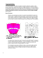
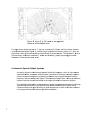
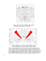
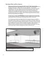
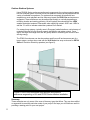
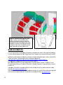
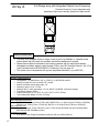
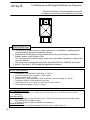
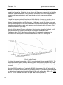
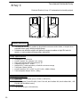
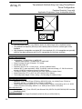
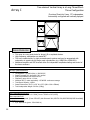
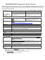
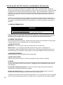
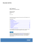
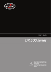
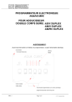
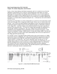
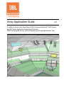
Array Application Guide v07 ® A Guide to Assist in the Specifying of JBL Precision Directivity 6000 Series and AE Series Application Engineered Products. With Pre-Designed Arrays, Venue Examples and Array Optimization Tips. Table of Contents Introduction Suspending Loudspeaker Arrays Array Applications: House of Worship/Speech Systems Performing Arts Venue Speech & Music Systems High-Impact Music and Dance Club Systems Indoor Arena Systems Outdoor Stadium Systems Array Tips: Modeling Arrays in Rooms Optimizing Long-Throw/Downfill Systems Signal Processing Low Frequency Pattern Control Subwoofer Cardioid Configurations Array Examples: Vertically Arrayed Enclosures Horizontally Arrayed Enclosures Vertical Arrays using Rotated Enclosures WRC and WRX Weather Resistant Configurations Painting AE & PD Enclosures AE & PD Series Connector Pin-out Guide 2 Page 3 4-5 6-10 11-16 16-17 20-23 24-26 27 28-29 30 Introduction This edition in the Array Application Guide series focuses on how Precision Directivity TM PD6000 Series loudspeakers offer solutions in constructing arrays that offer exceptional coverage and performance for a wide range of venue sizes and applications. The arrays in this guide, as in earlier editions, are organized by configuration and orientation. These configurations help emphasize the versatility of the PD Series loudspeakers as the arrays are upgraded in terms of coverage and output. General performance information including frequency range, nominal coverage, SPL capability, size, and weight are provided for each array. The versatility of the PD6000 Series allows it to easily integrate into designs that are primarily focused on speech intelligibility and music reproduction such as house of worship systems and theatrical venues, high level voice announce systems for indoor and outdoor sporting facilities, and even high level/high impact dance club environments. Currently, the PD6322/xx 3-way enclosure can be found in a variety of mid to larger size houses of worship and performing arts centers, often in a rotated enclosure orientation, to offer vertical directivity performance and control well into the critical lower mid-range frequency band to assist in speech intelligibility in problem acoustic spaces. These same advantages can also be used in large sporting event facilities to control energy onto court surfaces and ceiling areas. The PD6212/xx 2-way enclosures can be used in both individual hang points and multiple enclosure configurations to effectively address mid-size sporting facilities; the multiple horn patterns allow consistent horizontal coverage to conform to audience seating geometries with excellent results. When used with the PD5125 low frequency enclosure, the PD6200/xx mid-high frequency loudspeakers make up an effective single point cluster for very high speech intelligibility in theaters and worship spaces. Augmenting the PD6000 series with our Application Engineered Series is a natural when you need a smaller enclosure for downfill purposes to complete the system design. Many of the AE Series enclosures use the same rotatable high frequency horn types with the same highly predictable coverage patterns – up to 120o horizontal – to ensure the success of the system. New to the JBL Installations Series family are five additional AE Series subwoofer enclosures. These models include ultra compact 12” and 15” models, a dual 15” model, and two high-output 18” models in both single and dual component models. These new enclosures feature side rigging points at both the front and rear of the enclosure to facilitate easy enclosure suspension when configuring vertical arrays or rear firing elements in a flown cardioid subwoofer arrangement. Additional notes on cardioid subwoofer set-up can be found in the ‘Array Tips’ section. This easy and proven method of arranging subwoofer enclosures will assist the designer in minimizing rear projected energy to control low frequencies throughout the room. Although each room and project has its own demanding set of circumstances, we hope this Array Guide provides an outline for understanding the wide variety of effective solutions that are possible with the PD6000 Series of JBL Professional loudspeakers. 3 Suspending Loudspeaker Arrays IMPORTANT SAFETY WARNING! The information in this section has been assembled from recognized engineering data and is intended for informational purposes only. None of the information in this section should be used without first obtaining competent advice with respect to applicability to a given circumstance. None of the information presented herein is intended as a representation or warranty on the part of JBL. Anyone making use of this information assumes all liability arising from such use. All information presented herein is based upon materials and practices common to North America and may not directly apply to other countries because of differing material dimensions, specifications, and/or local regulations. Users in other countries should consult with appropriate engineering and regulatory authorities for specific guidelines. Correct use of all rigging hardware is required for secure system suspension. Careful calculations should always be performed to ensure that all components are used within their working load limits before the array is suspended. Never exceed the maximum recommended load ratings. Before suspending any speaker system always inspect all components (enclosure, rigging frames, pins, eyebolts, track fittings, etc.) for cracks, deformations, corrosion, missing, loose or damaged parts that could reduce strength and safety of the array. Do not suspend the speaker until the proper corrective action has been taken. Use only load-rated hardware when suspending Application Engineered™ Series and Precision Directivity® Series loudspeakers. Are You New to Loudspeaker Suspension? If so, you should do the following: Read and study JBL Technical Note Volume 1, Number 14: Basic Principles for Suspending Loudspeaker Systems (available at http://www.jblpro.com/pub/technote/tn_v1n14.pdf). Know the rules for the safe overhead suspension of loudspeakers. Attend a seminar, such as those recognized and recommended by the Entertainment Technician Certification Program http://etcp.esta.org/cert_recognized/training_programs/rigging_list.htm Meet and establish a relationship with a licensed mechanical or structural engineer. Get in the habit of asking them questions instead of guessing about their answers. Learn from what they tell you. Meet and discuss this aspect of your business with your Insurance Agent. Research and understand the codes, practices, and requirements in the venues where you intend to install and operate sound systems. General Hardware Information Any hardware used in an overhead suspension application must be load rated for the intended use. Generally, this type of hardware is available from rigging supply houses, industrial supply catalogs and specialized rigging distributors. Local hardware stores do not usually stock these products. Hardware that is intended for overhead suspension will comply with ASME B30.20 and will be manufactured under product traceability controls. Compliant hardware will be referenced with a working load limit (WLL) and a traceability code. Attachment to Structures A licensed Professional Engineer must approve the placement and method of attachment to the structure prior to the installation of any overhead object. The following performance standards should be provided to the Professional Engineer for design purposes; Uniform Building Code as applicable, Municipal Building Code as applicable, and Seismic Code as applicable. 4 The installation of the hardware and method of attachment must be carried out in the manner specified by the Professional Engineer. Improper installation may result in damage, injury or death. Inspection & Maintenance Suspension systems are comprised of mechanical devices and, as such, they require regular inspection and routine maintenance to insure proper function ability. JBL AE Series and PD Series loudspeakers must be inspected for fatigue at least annually. The inspection shall include a visual survey of all corners and load bearing surfaces for signs of cracking, water damage, de-lamination, or any other condition that may decrease the strength of the loudspeaker enclosure. Accessory rigging hardware provided with or for the JBL AE Series loudspeakers must be inspected for fatigue at least annually. The inspection shall include a visual survey of the material for signs of corrosion, bending or any other condition that may decrease the strength of the fastener. Additionally, any eyebolts shall be checked for possible spin-out from the enclosure. For all other hardware and fittings, refer to the hardware manufacturer's inspection and maintenance guidelines for process. JBL is not responsible for the application of its products for any purpose or the misuse of this information for any purpose. Furthermore, JBL is not responsible for the abuse of its products caused by avoiding compliance with inspection and maintenance procedures or any other abuse. Prior to suspending the system, an expert, trained and experienced in suspending loudspeaker systems should inspect all rigging parts and components. Safe Rigging WARNING! Suspending any loudspeaker system should be done by qualified persons following safe rigging standards. The JBL AE Series and PD6000 Series are supplied with built-in internal brackets. The system is designed to facilitate the suspension of the loudspeaker by a qualified person familiar with rigging hardware and industry practices. Threaded M10 shouldered eyebolts are available for purchase from JBL Professional (part # 229-00009-01) for use when suspending AE and PD Series enclosures utilizing this internal bracket system. AE Series and PD6000 Series enclosures are capable of a maximum load of 470lbs/213kg from 2 points equally loaded. The single point maximum load is 235lbs/106kg. Improper installation may result in damage, injury or death. Prior to suspending the system, an expert, trained and experienced in flying speaker systems should inspect all rigging parts and components. A licensed Professional Engineer must approve the placement and method of attachment to the structure prior to the installation of any overhead object. 5 Array y Applica ations The arrrays describe ed in this gu uide are deve eloped to me eet the perfo ormance goa als of a wide e variety of applicatio ons. Array re ecommendattions are larg gely dictated d by the intended functio on of the sou und system along a with th he size and geometry g of the audiencce area. Forr these discu ussions we will divide the primary function of the so ound system m into severa al categories: Speech, Speech & Musicc, High-Impa act Music an nd Dance Syystems, and Indoor and Outdoor spo orts systemss and offer so ome typical solutions s to these t comm mon design challenges. c R Referenced a array examp ples begin on o page 17. Speech Systems s A speech-only system’ss primary fun nction is to provide p high intelligibility throughout the audience arreas. For the ese mid-size ed rooms the ere is more of o a tendenccy to use a ce enter cluster syste em, sometim mes with a distributed de elay system for deeper seating s posittions. Center clustters provide good localizzation to the e talker. Dela ay fills can im mprove cove erage and offer mo ore even dirrect-to-refleccted energy, but at an inccreased cosst. These sysstems For medium m sized to larrge sized roo oms, Precisiion Directivitty 6000 Serie es™ two-wa ay and mid-high en nclosures are e most appro opriate. In the above exxamples a th hree element array using two PD6200/64 P m mid-high enclosures flankking a low frrequency enclosure will provide a single point so ource, highlyy intelligible voice cluste er. For fan-shaped rooms or o larger aud ditoriums, a threet or fou ur-cluster sysstem provide es stent horizon ntal coverage and betterr localization n to the stage e. Systems more consis designed prrimarily for speech will id deally have minimum m ovverlap between adjacent enclosures or clusters. 6 Figure 3: 3 Array G (p. ( 24) used d as an exp ploded cluster in n a fan-sha aped room For larg ger center clusters arrayys C - F mayy be considered. For thre ee- and four--cluster systtems as desccribed above e (see Figure e 3), verticall arrays of ro otated enclossures, arrayys G, H, and I are particularly useful given g their exxcellent verttical directivity characterristics. The stacked s LF drivers d of these e arrays com mbine to incrrease LF pow wer and dire ectivity, greatly improving g gain beforre feedbacck on lower performance e areas. Combiination Speech & Mu usic System ms A majority of o sound rein nforcement projects p fall into i this cate egory. Here, all the elem ments associated with w a succe essful speecch system (evenness of coverage, c co onsistent pa attern control, and d good intellig gibility) need d to be comb bined with a system thatt goes lowerr in frequency and a providess greater imp pact. These systems s ben nefit from a strong s prosccenium system to provide sourcce localizatio on to the stage and solid d low-frequency support. The preferre ed configura ation of these e systems iss often an exxploded arrangement, although other buildin ng constraints or prefere ences may dictate d otherw wise (see Figures 4 & 5)). Clusters mu ust provide good g directivvity to lower frequencies f p even nness in order to provide of coverage e and improvved system gain g before feedback. f 7 Figure 4: Array A H (p. 25) with de elay locations used in an exploded configurration in an auditorium m Fig gure 5: Arra ay A (p. 17)), with horn patterns sh hown, used d in an exploded configuratio c on. Red are eas show minimal m overrlap. Some of the e array typess described incorporate subwoofers integrated into the arrayy; others do no ot. Subwoofe ers are often n a requirem ment for syste ems requirin ng higher impact and low freq quency extension and ca an always be flown adja acent to, beh hind the main n array, or in a ground support configuration. Add ding a smalle er full range enclosure such s as the AC Com mpact Serie es model AC C28/95 on top p of or near ground supp ported subw woofer locations will assist in th he integratio on of these subwoofers for f near listener positions. 8 High-Impact Music and Dance Systems While these systems are also sometimes used for speech, their primary purpose indicates that the arrays must produce high SPL Levels and have extended bandwidth by integrating subwoofers – whether flown or ground supported – into the system. Rectangular and auditorium shapes can have enhanced L/R only systems or exploded cluster systems – the center channel sometimes being optimized for speech. Fanshaped rooms once again typically will use three- or four arrays to provide proper coverage and localization to the stage. Using rotated and vertically oriented enclosures, as shown with array type G on page 24, will provide high impact and excellent vertical directivity in the low frequency bandpass. A similar use for a single rotated PD6322/xx is for high level dance club environments. The strong impact of the dual 12” low-frequency section is highly effective when used for square dance floors (4 enclosures) or rectangular dance floors (6 enclosures). In club environments where even higher levels of low frequency impact is desired the array type B, shown on page 18, will create a truly ‘world class’ level dance system (see Figure 6). The enclosures would be rotated 90o with the 12” devices on either side of the mid and high-frequency horns. Where the standard array type F offers increased vertical pattern control when oriented vertically this rotated configuration offers better low frequency control horizontally, keeping low frequency energy onto the dance floor while allowing less impact to adjacent seating areas outside of the dance floor. Figure 6: Array Type F14 (p. 23) Rotated PD6322/xx enclosure with additional PD5122 dual 12” low frequency enclosure. 9 Indoor Arena Systems Designing PD6000 Series enclosures into an indoor arena/field house facility can be addressed in several manners depending on the size of the facility. For larger capacity bleacher seating units that run the length of a court, using horizontally oriented PD6212/xx or PD6322/xx enclosures distributed along the length of the bleacher seats works well. Ideally these distributed speaker positions will orient in front of the first seating row. Depending on the height of the bleacher sections and associated vertical coverage requirements the horn may be left in its standard orientation with the enclosure rotated as mentioned above. With a 60o x 40o model this would allow the 60o pattern to cover the bottom to uppermost row when used with a taller bleacher section. Larger capacity arenas that utilize a suspended scoreboard and/or video display panels may benefit from speakers positioned at the top or above the scoreboard area in a circular configuration as shown below. This design approach works very well with full wrap around seating areas. This tighter perimeter of speakers helps keep time arrivals within an acceptable time window as well. Figure 7: PD6322/xx and PD5122 enclosures – used for better vertical pattern control shown positioned above a scoreboard with PD6212/xx enclosures suspended for upper perimeter seating areas as a delay ring. 10 Outdoor Stadium Systems Using PD6000 Series enclosures as the main components for a pole mounted or press box roof oriented system for small to mid-size stadiums is easily accomplished with the variety of available horn patterns. For systems that are speech oriented with less emphasis on music playback and low frequency impact the PD6212/xx enclosures are suggested. These enclosures may be arrayed horizontally or vertically depending on mounting location and seating geometry, but will typically be ordered with the –WRX weather protection treatment. Remember when specifying rotated –WRC and –WRX to add the ‘-H’ suffix to indicate rotated horn patterns if so desired. For canopy hung systems, typically seen in European football stadiums, vertical arrays of rotated enclosures will offer superior speech intelligibility and pattern control. Once again, the larger mid-range horn size will greatly assist in controlling the volume of late arriving energy. The PD6212 enclosures can also be used as specific area fill enclosures as part of a larger system; such as when used with the VLA Series line array enclosures or PD700 Series of Precision Directivity speakers (see figure 8). Figure 8: PD6212/xx enclosures used as down firing area fill enclosures augmenting a VLA and PD700 Series stadium installation. Summary These examples are only some of the uses of the array types that follow. They can be modified or augmented to meet the particular needs of your project. We hope you will find them useful in providing a starting point for your next project. 11 ARRAY TIPS Modeling Arrays in Rooms The arrays included in this array guide have been developed to provide good coverage consistency throughout their specified range and balanced power response throughout their bandwidth. They are arranged to produce systems that are easy to rig and meet common coverage and performance needs. To better understand how these arrays will work in a particular room, it is always preferred to model the room with EASE, CATT acoustic or a similar type of predictive analysis tool. With these tools, array orientation and angles can be adjusted to optimize their use in the room. It is also a good way to determine how different elements of the system – multiple arrays and fills – combine to produce the complete solution. Optimizing Long-throw/Short-throw Loudspeaker Systems Many sound reinforcement applications call for loudspeakers to be arranged in a “longthrow/short-throw” configuration. To set-up a system like this, we recommend the following procedure: 1) Optimize the long-throw loudspeaker or system by itself (including separate LF). Store your optimized trace for later reference. 2) Optimize the short-throw (downfill) speaker by itself (with long-throw off). Note: When using a full-range downfill device, use the same high-pass as the long-throw device. For a mid-high downfill device, use the same high-pass as the long-throw M/H high-pass. This is important since using different crossover points is detrimental to how the loudspeakers interact due to phase mismatches through the crossover regions. 3) Level balance the downfill on-axis measurement to match the long-throw loudspeaker’s on-axis measurement. This should be done above 1 kHz, where both devices are clearly in the effective range of the waveguide. This may be done by matching traces on an analysis system such as Smaart or TEF; or by simply using an SPL meter. 4) With both long-throw and short-throw sections on, analyze the downfill region again. The additional energy in this region, which resulted from the combined contribution of the long-throw device(s) and the downfill device, may be reduced by adding broad parametric EQ cuts to the downfill loudspeaker. Note: The use of parametric filters introduces less phase shift between the long-throw and downfill devices than raising the high-pass crossover point of the downfill loudspeaker, ultimately creating a smoother transition between the devices. 5) If both loudspeakers are full-range devices, the addition of the down-fill device will affect the long-throw response by increasing level in the LF region. This is usually beneficial since the overall array will provide greater LF levels, producing a more 12 balanced system and better LF polar characteristics. However, this means that the final low-frequency EQ must be done with all devices on. Note: Below 250 Hz, treat all components of the array as one device with the same EQ filters. This proven procedure provides very good, consistent results for this common arrangement. Signal Processing Loudspeakers shown in this array guide are described in their most passive configuration; the number of DSP channels required and amplifier recommendations shown for each array type reflect this. A separate DSP channel is required for the downfill loudspeakers. The low-frequency section of a three-way system or separate LF enclosure will require an additional DSP channel, as will the subwoofers. DSP signals for each individual array may be paralleled symmetrically. For instance, where two loudspeakers are side by side horizontally, there is no benefit to providing independent DSP. Level differences may be done at the amplifier if required. Loudspeaker DSP settings may be found on the JBL web site. For the crossover between the subwoofers and the low-frequency section, a 24 dB/octave L-R crossover slope on each side is recommended. Also, it is good practice to use as a minimum an 18 dB/octave high-pass on the system with the corner frequency somewhere between the – 10dB and –3dB down point of the loudspeaker reproducing the lowest frequency. Refer to the loudspeaker specifications for this data. Low Frequency Pattern Control Most of the arrays described in this guide have integral to them low-frequency devices that are arranged to provide improved directivity. No special DSP techniques are required to realize these benefits. It is generally better to arrange LF devices vertically rather than horizontally, as the vertical arrangement tends to collapse the vertical polar pattern, which is beneficial in keeping energy off of the stage and projecting it into the room. Where it is important to limit the LF energy on the stage and to gain additional level and impact, look for solutions that stack two or more LF drivers vertically. To further explore low-frequency arraying please refer to the following JBL white papers: 1) Basic PD5322 and PD5122 Array Applications; Technical Notes Volume 1, Number 32. 2) Forward Steered Arrays in Precision Directivity Speaker Systems; Technical Notes Volume 1, Number 28. 3) Loudspeaker Array Low-Frequency Pattern Control using Filtered Array Technology; JBL Professional Application Note. 13 4) JBL Audio Engineering for Sound Reinforcement by John Eargle and Chris Foreman (Hal Leonard Publications, 2002). These papers describe some of the most popular and effective low-frequency arraying techniques for performance systems including: Frequency-shaded or Bipole arrays Gradient or Cardiod arrays Filtered Array Technology (FAT) arrays Forward Steered arrays Each of these arrays may be realized using product from the AE and PD series of loudspeakers. For additional information on the use of these arrays please contact the JBL Application Support staff. Subwoofer Cardioid Configurations Configuring subwoofer enclosures in vertical columns or spaced vertical arrays, as with any line source, will allow the user to achieve vertical pattern control to a lower frequency. The AE Series subwoofers can easily be used in such configurations with ample 10mm attachment points. A more common configuration for practical low frequency control, however, is to use multiple subwoofer enclosures in a cardioid configuration. Figure 7: ASB6112 enclosures configured in a cardioid configuration. Cardioid subwoofer arrays will typically exhibit 12-25dB of rear attenuation to better control subwoofer energy onto stage areas or boundary areas. The beneficial effects are tighter, more controlled subwoofer impact to the audience areas due to higher direct to reverberant ratios, less energy interacting with boundary conditions (walls), and late arriving energy from other distributed subwoofer arrays in arena situations. These performance gains are achieved by matching the rear facing enclosures frequency response and amplitude to the forward facing enclosures response and amplitude at a rear test microphone position approximately 5 meters behind the array. The rear facing cabinet is then time delayed to the arrival from the forward facing enclosures and the rear enclosures polarity is then reversed. The rear attenuation can then be compared to the front of the cardioid array by moving the test mic to a position in front of the array at an identical distance as was used behind the array. 14 d Spherica al Array exa amples Planarr Array and The followin ng 3-D mode eling plots sh how the effect mentioned above whe ere unwante ed energy from m the outer enclosures e off a planar arrray is directted onto the side walls of o a room (fig. 8). The rear delay d clusterr is also a pla anar array which w exhibitts the same problems. Planar P arrayss refer to tho ose clusters that have a flat top and bottom array surface. Figure 8: 8 Planar arra ays used forr main and dela ay center loccations. The second d example sh hows the sam me three enclosures arrranged in a spherical s arrray with independent aiming g capabilities (fig. 9). No ote that the direct d side wall w energy iss lessened wiith this arrayy type which also uses distributed d de elay enclosu ures for the three rear audienc ce areas. Th his distribute ed delay con nfiguration will also offer better localization to the stage e for the resp pective seating areas. Th his is the pre eferred desig gn direction.. 15 Figu ure 9: Spherrical array ussed for main clusster location with distribu uted delay encllosures show wing reduced side wall energy and bettter coverage e. In this room m exam mple the sph herical arrayy allows bettter cove erage to the three front seating s area as than n is possible with the pla anar array. E INFORM MATION MORE For more informatio on on design ning loudspe eaker system m arrays, reffer to JBL Au udio Enginee ering for Sound Reinforce ement by Jo ohn Eargle and a Chris Fo oreman (Hal Leonard Pu ublications, 2002) 2 Addition nal system design d inform mation, inclu uding advancced design concepts, c ca an be found at a the "Technical Library” available on n the JBL Prrofessional website w at http://w www.jblpro.co om/catalog/g general/technicallibrary.a aspx?CatID= =27&Run=1 For add ditional inform mation on lo ow frequencyy control refe er to – Basic PD5322 P and PD5122 Arrray Applicatiions; Techniical Notes Volume 1, Nu umber 32 and Forward d Steered Arrays in Preccision Directtivity Spea aker Systemss; Technical Notes Volume 1, Number 28. Informa ation on amp plifier recomm mendations found in thiss guide can be obtained d at the Crow wn website e: http://www w.crownaudio o.com/ Informa ation on DSP P hardware recommenda r ations found d in this guide can be ob btained at the e BSS Audio, Crown C and dbx d websitess. All websites are acce essible from:: http://jblpro o.com/ . 16 Array A Full Range array with Integrated, Bipole Low Frequency Precision Directivity 3-way loudspeaker with Application Engineered vertically splayed mid-high downfill ARRAY OVERVIEW This array is an excellent choice for larger rooms as part of a Left/Right or exploded cluster system where high SPL levels and excellent gain before feedback are required. Spaced-Source dipole low-frequency driver arrays combine with the large mid-frequency waveguide to maintain pattern control through 125Hz. (see JBL Technote Volume 1, No. 32 for more information about PD5322/PD5122 LF steering). Also see page 18. This system may be augmented with ground supported subwoofers. (e.g. ASB7128) Array Specifications Loudspeakers: (1) PD6322/64 or /95, (1) PD5122, (1) AM7200/95 downfill Overall Coverage: 60/90 horizontal x 85 vertical Downfill enclosure vertical splay angle: -50 Frequency range: 41 Hz – 19 kHz Maximum SPL (1 meter equivalent): LF: 134, MF/HF: 134 dB-SPL continuous average Total Power Capacity: 3900w Overall Dimensions: 82” H x 26.5” W x 29” D (2077 x 673 x 737mm) Total Loudspeaker Weight: 314 lbs. (142.5kg) Recommended Amplification: PD6322 LF 1 ch. 2000w [Crown I-T5000 HD], PD6322 M/H: 1 ch. 600w [Crown CTs1200 or DCi2/600], PD5122: 1 ch. 2000w [Crown I-T5000 HD], AM7200: 1 ch. 600W [Crown CTs1200 or DCi2/600] Recommended DSP: 3 channels required. [Crown PIP-USP3, Crown I-Tech HD, dbx DriveRack 260, dbx DriveRack 4800, BSS FDS-366, BSS SoundWeb London] Available Accessories 3 pc. M10 x 35mm Forged Shouldered Eye-Bolt Kit (JBL part #229-00009-01) 17 Array B Full Range array with Integrated Bipole Low Frequency Precision Directivity 3-way loudspeaker array with companion spaced-source low frequency enclosure ARRAY OVERVIEW This array is an excellent choice for larger rooms as part of Left/Right or exploded clusters where exceptional gain before feedback is required. Spaced-source low-frequency drivers combine with the large mid-frequency waveguide to maintain pattern control through 125Hz. This array may form the basis of larger arrays where polar pattern consistency is required to a very low frequency. This system may be augmented with ground supported ASB7128 or ASB6128V subwoofers. Refer to Tech Note V1 #32 for additional application information. Array Specifications Loudspeakers: (1) PD6322/64 or PD6322/95, (1) PD5122 Overall Coverage: 60/90 horizontal x 40/50 vertical Frequency range: 41 Hz – 19 kHz Maximum SPL (1 meter equivalent): MF/HF 134 dB-SPL continuous average, LF: 134 dB Total Power Capacity: 2700W continuous pink noise Overall Dimensions: 54” H x 26.5” W x 28” D (1323 x 673 x 706 mm) Total Loudspeaker Weight: 250 lbs. (113.6 kg) Recommended Amplification: PD6322 LF and PD5122: 2 ch. 2000w (Crown IT5000 HD), M/H: 1 ch. 600w (Crown CTs 1200 or DCi2/600) Recommended DSP: 2 channels required. [Crown PIP-USP3, Crown I-Tech HD, dbx DriveRack 260, dbx DriveRack 4800, BSS FDS-366, BSS SoundWeb London] Processing for both LF sections is identical for standard use. Available Accessories 18 3 pc. M10 x 35mm Forged Shouldered Eye-Bolt Kit (JBL part #229-00009-01) Array B Application Notes A sometimes unanticipated problem in sound system design is excessive low frequency energy beneath the flown array. Related to this can be poor low frequency coverage into the audience area and a system with excessive ‘lobing’ onto the performance area. This is usually caused by arranging low frequency devices in such a way they do not work together in an efficient manner. A single low-frequency device by itself has very little directivity. However, by spacing a pair of low frequency devices the resulting ‘spaced-source’ array has a directivity defined by the distance between the devices and the frequency. Additionally, spacing the drivers above and below the MF waveguide has the effect of extending the effective working height of the system, thus allowing the resulting array to work together smoothly through a lower frequency. This is commonly known as a dipole array. Not only will this reduce LF energy on the stage, thus increasing gain before feedback, it will also have the effect of improving the evenness of coverage in the audience area. The diagram below (Fig 1.) describes how the levels of the loudspeaker system must be controlled in the vertical plane to achieve consistent direct levels in the seating area. Fig. 1: Section Drawing To achieve the spaced-source effect, a PD5122 is simply placed below a standard PD6322. The low frequency device spacing creates a directivity pattern that essentially matches that of the mid-frequency waveguide. The result is a smooth transition in directivity performance through crossover. Since the PD5122 is simply the LF section of a PD6322, the response of the LF sections will be identical and they can utilize the same DSP processing settings. No additional steps are required to realize the increased vertical directivity offered by this array configuration. Refer to JBL Tech Note V1 #32 for additional information and polar data concerning this array. 19 Array C Two-element Horizontal Array Precision Directivity 2-way 12” loudspeakers horizontally splayed ARRAY OVERVIEW This array can be used for medium to large-sized rooms as a center cluster, or as part of an exploded cluster design utilizing multiple arrays. Provides a cost-effective solution with defined coverage at medium to high SPL levels for speech, or music systems utilizing auxiliary subwoofers. Array Specifications Loudspeakers: (2) PD6212/64 Overall Coverage: 110 horizontal x 40 vertical Splay angle between PD6212/64 enclosures: 60o Frequency range: 80 Hz – 18 kHz Maximum SPL (1 meter equivalent): 135 dB-SPL continuous average Total Power Capacity: 2400W Overall Dimensions: 39” H x 58.5” W x 33” D (991 x 14868 x 839mm) Total Loudspeaker Weight: 304 lbs. (138kg) Recommended Amplification: PD6212/64 x 2: 1 ch. 1500W [Crown CTs3000 or DCi2/1250] Recommended DSP: 1 channel required. [Crown PIP-USP3, Crown I-Tech HD, dbx DriveRack 260, dbx DriveRack 4800, BSS FDS-366, BSS SoundWeb London] Available Accessories 3 pc. Eye-bolt kit (part # 229-00009-01) 20 Array D Three-element Horizontal Array in a Wide Coverage Configuration PD6200 Mid/High loudspeakers vertically oriented with PD5125 Low Frequency Enclosure ARRAY OVERVIEW This array is a very good choice for medium to large rooms as a center cluster speech system offering very high intelligibility and excellent pattern control. Array Specifications Loudspeakers: (2) PD6200/64, (1) PD5125 Low Frequency Enclosure Overall Coverage: 110 horizontal x 55o vertical Splay angle between PD6200/64 enclosures: 60o Frequency range: 40 Hz – 19 kHz Maximum SPL (1 meter equivalent): LF: 141, MF/HF: 141 dB-SPL continuous average Total Power Capacity: 7200W Overall Dimensions: 46.2” H x 83” W x 45.3” D (1174 x 2108 x 1151 mm)* Total Loudspeaker Weight: 378 lbs. (172 kg) * With a nominal 20o down tilt of all enclosures Recommended Amplification: PD6200/64 x 2: 1 ch. 1000W [Crown CTs2000 or DCi2/1250], PD5125: 1 ch. 1000W [Crown CTs2000 or DCi2/1250] Recommended DSP: 2 channels required (2 channels for Medium Power). [Crown PIP-USP3, Crown I-Tech HD, dbx DriveRack 260, dbx DriveRack 4800, BSS FDS-366, BSS SoundWeb London] 21 Array E Two-element Horizontal Array with Downfill Precision Directivity 3-way loudspeakers horizontally splayed with vertically splayed Application Engineered mid-high downfill ARRAY OVERVIEW This array is a very good choice for medium to large rooms as a center cluster or as part of a high-impact Left/Right or exploded cluster system. The four 12” low frequency drivers combine to provide solid LF response and improve horizontal directivity. Array may be augmented ground stacked ASB6128V subwoofers to create a system with excellent pattern control and high-impact music capabilities. Array Specifications Loudspeakers: (2) PD6322/64, (1) AM7200/95 downfill. Overall Coverage: 110 horizontal x 85 vertical Splay angle between PD6322 enclosures: 60o Downfill enclosure vertical splay angle: -50o Frequency range: 41 Hz – 19 kHz Maximum SPL (1 meter equivalent): LF: 134, MF/HF: 134 dB-SPL continuous average Total Power Capacity: 4150W Overall Dimensions: 66” H. x 58.5” W. x 33” D. (1677 x 1486 x 839 mm) Total Loudspeaker Weight: 404 lbs. (184 kg) Recommended Amplification: PD6322 LF x 2: 2 ch. 2000W [Crown I-T5000 HD], PD6322 M/H x 2: 2 ch. 600W [Crown CTs1200 or DCi2/600], AM7200/95: 1 ch. 600W [Crown CTs1200 or DCi2/600] Recommended DSP: 3 channels required. [Crown PIP-USP3, Crown I-Tech HD, dbx DriveRack 260, dbx DriveRack 4800, FDS-366, BSS SoundWeb London] Available Accessories: 3 pc. Eye-bolt kit (part # 229-00009-01) 22 BSS Array F Two-element Horizontal Array with Bipole LF and Downfill Precision Directivity 3-way loudspeakers horizontally splayed with spaced-source LF and downfill ARRAY OVERVIEW This array is an excellent choice for medium to large rooms as a center cluster or as part of a high impact Left/Right or exploded cluster system. Spaced source 12” drivers (PD6322 + PD5122) create directivity through 125 Hz to improve gain before feedback and optimize evenness of coverage. (See JBL Technote Volume 1, No. 32 for more information about PD5322/PD5122 LF steering. also see page 18.) Array may be augmented ground stacked subwoofers such as the ASB7128 to create a system with optimized pattern control and high impact music reinforcement. Array Specifications Loudspeakers: (2) PD6322/64, (2) PD5122, (1) AM7200/95 downfill. Overall Coverage: 110 horizontal x 85 vertical Splay angle between PD6322/5122 enclosures: 60o Downfill enclosure vertical splay angle: -50o Frequency range: 41 Hz – 19 kHz Maximum SPL (1 meter equivalent): LF: 140, MF/HF: 134 dB-SPL continuous average Total Power Capacity: 7350W Overall Dimensions: 80” H x 58.5” W x 35” D (2032 x 1486 x 889 mm) Total Loudspeaker Weight: 630 lbs. (286 kg) Recommended Amplification: PD6322 LF x 2: 2 ch. 2000W [Crown I-T5000 HD], PD6322 M/H x 2: 2 ch. 600W [Crown CTs1200 or DCi2/600] PD5122 x 2: 2 ch. 2000W [Crown I-T5000 HD], AM7200/95: 1 ch. 600W [Crown CTs1200 or DCi2/600] Recommended DSP: 3 channels required. [Crown PIP-USP3, Crown I-Tech HD, dbx DriveRack 260, dbx DriveRack 4800, BSS FDS-366, BSS SoundWeb London] Available Accessories: 3 pc. Eye-bolt kit (part # 229-00009-01) 23 Array G Two-element Vertical Array in a Long-Throw/ShortThrow Configuration Precision Directivity 3-way loudspeakers horizontally configured and vertically splayed ARRAY OVERVIEW This low-profile array is an excellent choice for larger L/R, exploded cluster, or dance systems. The four, stacked low-frequency drivers provide useful pattern control through 200Hz to increase gain before feedback and provide even room coverage. H.F. waveguides are rotated 90o from standard. The upper enclosure may use 60o x 40o waveguides and the lower 60o x 40o or 90o x 50o waveguides. More than two enclosures may be used for increased vertical coverage. Array Specifications Loudspeakers: (1) PD6322/64, (1) PD6322/95 Overall Coverage: 60/90 horizontal x 85 vertical Vertical splay angle: 45o Frequency response: 41 Hz – 17 kHz Maximum SPL (1 meter equivalent): LF: 134, MF/HF: 134 dB-SPL continuous average Total Power Capacity: 3800W Overall Dimensions: 53” H x 39” W x 36” D (1347 x 991 x 915mm) Total Loudspeaker Weight: 340lbs. (155kg) Recommended Amplification: PD6322 LF x 2: 2 ch. 2000W [Crown I-T5000 HD], PD6322 M/H x 2: 2 ch. 600W [Crown CTs1200 or DCi2/600] Recommended DSP: 4 channels required. [Crown PIP-USP3, Crown I-Tech, dbx Driverack 260, BSS FDS-334, BSS FDS-366, BSS SoundWeb] Available Accessories 3 pc. M10 x 35mm Forged Shouldered Eye-Bolt Kit (JBL part #229-00009-01) 24 Array H Two-element Vertical Array in a Long-Throw/ShortThrow Configuration Precision Directivity 3-way with Application Engineered 2-way loudspeaker downfill ARRAY OVERVIEW This low-profile array is a very effective choice for mid to large L/R or exploded clusters. The stacked low-frequency drivers provide vertical pattern control to increase gain before feedback. High frequency waveguides are rotated 90o from standard. 60o x 40o waveguides are generally used for the upper enclosure and 90o x 50o waveguides for the lower enclosure. Array Specifications Loudspeakers: (1) PD6322/64, (1) AM7212/95 Overall Coverage: 60/90 horizontal x 70 vertical Vertical splay angle: 45o Frequency range: 41 Hz – 18 kHz (41 Hz – 18 kHz for Medium Power) Maximum SPL (1 meter equivalent): MF/HF 134 dB-SPL continuous average, LF: 128 dB continuous average 133 dB-SPL continuous average for Medium Power Total Power Capacity: 2100W continuous pink noise (1800W for Medium Power) Overall Dimensions: 55” H x 26.5” W x 28” D (1400 x 673 x 706mm) Total Loudspeaker Weight: 221lbs. (101kg) (215 lbs (98kg) for Medium Power) Medium Power Solution: (1) PD6322/64, (1) AM5212/95 Recommended Amplification: PD6322 LF: 1 ch. 1250W [Crown CTs3000 or DCi2/1250], M/H: 1 ch. 600W [Crown CTs1200 or DCi2/600]; AM7212: 1 ch. 600W [Crown CTs1200 or DCi2/600] Medium Power Solution: PD6322 LF: 1 ch. 1250W [Crown CTs3000 or DCi2/1250], M/H: 1 ch. 600W [Crown CTs1200 or DCi2/600]; AM5212: 1 ch. 300W [Crown CTs600 or DCi2/300] Recommended DSP: 3 channels required. [Crown PIP-USP3, dbx Driverack 260, BSS FDS-334, BSS FDS-366, BSS SoundWeb, SoundWeb London] Available Accessories 3 pc. M10 x 35mm Forged Shouldered Eye-Bolt Kit (JBL part #229-00009-01) 25 Array I Two-element Vertical Array in a Long-Throw/ShortThrow Configuration Precision Directivity 2-way 12” loudspeakers horizontally configured and vertically splayed ARRAY OVERVIEW This array is a very good choice for larger L/R or exploded clusters. High-frequency waveguides are rotated 90o. This is an excellent array for high-powered speech systems and may be augmented with subwoofers to create true full-range music reproduction (e.g. ASB6128 or ASB6128V). Additional amplifier and DSP channels allow for independent amplitude shading and control of the lower enclosure. Array Specifications Loudspeakers: (1) PD6212/64, (1) PD6212/95 Overall Coverage: 90 horizontal x 80 vertical Splay angle between PD enclosures: 45o Frequency range: 80 Hz – 18 kHz Maximum SPL (1 meter equivalent): 135 dB-SPL continuous average Total Power Capacity: 1100W Overall Dimensions: 58.5” H x 39” W x 33” D (991 x 991 x 839mm) Total Loudspeaker Weight: 304 lbs. (138kg) Recommended Amplification: PD6212/64 and /95: 2 ch. 1500W [Crown CTs3000 or DCi2/1250] Recommended DSP: 2 channels required. [Crown PIP-USP3, dbx Driverack 260, BSS FDS-334, BSS FDS-366, BSS SoundWeb] Available Accessories 3 pc. Eye-bolt kit (part # 229-00009-01) 26 WEATHER RESISTANT Configurations for AE, PD & VLA Series JBL offers two standard levels of weather resistance for AE, PD and VLA Series loudspeakers. WRC is intended for outdoor placement where the loudspeaker will be sheltered from direct exposure to the elements. WRX is best suited for direct exposure to the elements or any extreme environment such as tropical climate, beach areas, or other locations with high or low temperature extremes, salt air, high humidity or rapid change in temperature. Model Numbering – WR designation is a suffix to the standard model number. For example: AM5215/95-WRC or AM5215/95-WRX. MODEL SUFFIX ENVIRONMENTAL RATINGS ENCLOSURE Covering and Finish Dimensions Standard Color Optional Colors Custom Colors Horn Orientation Enclosure Hardware -WRC Covered/Protected Outdoor Areas -WRX Direct Exposure or Extreme Environment IP55 per IEC 529 IP56 per IEC 529 Exterior: 0.060” (1.5mm) thick DuraFlex coating Interior: Wood sealer Exterior: Course Texture 0.060 “(1.5mm) thick Fiberglass, all corners wrapped with fiberglass cloth for maximum structural reinforcement. Interior: Gelcoat sealed LARGER than standard AE Series cabinets. Standard AE Series brackets do NOT fit these cabinets. Visit the JBL Professional website for drawings at: http://www.jblpro.com/catalog/support/getfile.aspx?doctype=3&docid=1970 Or, contact JBL Professional for dimensional information. LIGHT GRAY, similar to RAL 7035 and Pantone PMS428C (contact JBL Professional for availability) JBL Black & JBL AE White (contact JBL Professional for availability) Contact JBL Professional for colors, pricing, and availability Rotating the horn in the field is not recommended. Default horn orientation is wider horizontal coverage, narrower vertical coverage with vertical cabinet orientation, same as standard versions. To order with horn rotated, add “-H” (Ex: AM5215/95-WRX-H) Exterior grade plywood, exterior grade glues, fully captive baffle Stainless steel and heavily zinc-plated hardware throughout GRILLE Shape Grille Material Grille Backing Flat front Perforated stainless steel, vinyl dipped, light gray color Black open cell foam over stainless steel vapor-barrier INPUT & NETWORK Input Connection & Cable Network Mode Sealed gland nut, permanently attached 20 ft (6 m) captive jacketed cable, unterminated. AE Compact models are equipped with a 6 ft (2 m) captive jacketed cable, un-terminated. Cable rated for permanent outdoor installation: UV, ozone & water resistant. Custom cable lengths are available, contact JBL Pro for details. Cable Diameters: (14/2 .350” - .380”); (14/4 .350” - .380”); (14/6 .400” - .450”) Comes standard in “most passive” mode: bi-amp on normally bi-amp/tri-amp models (i.e., AM73xx models), full passive on normally passive/bi-amp models. Mode is NOT re-configurable in the field. To order in bi-amp or tri-amp mode add –BA or –TA suffix respectively, as applicable (Ex.: AM7215/95WRC-BA or AM7315/64-WRX-TA) COMPONENT TREATMENT Transducers Passive Crossover Network Cones treated for water resistance, metal parts urethane-coated Conformal urethane-coating Delivery – WRC and WRX are Build-to-Order products, not stocked. Lead time (from when the order is cleared by the JBL Credit Department to shipment from JBL Professional) is typically 6 to 8 weeks. Additional time is required for custom color or deviations (contact the JBL Professional for pricing and availability). Custom Extra-Cost Options: (contact JBL Professional for pricing and availability) Custom cable lengths Custom color options (other than standard GRAY) 27 Painting AE and PD Series Loudspeaker Enclosures JBL AE and PD Series loudspeakers are available in black, white or unfinished. When ordering, the default color is always black. White is signified by a –WH suffix on the model number. Unfinished models are signified with a –UF suffix and are delivered “paint ready”. JBL recommends that for custom color installations, the unfinished versions (-UF) should be ordered and painted as required. If however, you wish to paint an enclosure over the JBL “Duraflex” finish, the instructions below should be used as a general guide. DuraFlex is a multi-layer finish. The top aliphatic layer provides a surface to which most paints bond. Note: Some JBL portable loudspeaker models do not include a top aliphatic coating – these models are not paintable. All standard AE and PD Series loudspeakers do include a top aliphatic coating and are paintable. 1) SURFACE PREPARATION Important: Do NOT sand or scuff the surface! This could remove the top aliphatic coating which is required for good paint adhesion. Prepare the surface by cleaning and wiping dust with a damp cloth. It may be necessary to use a mild household cleaner to remove grease. If so, be sure to rinse off the detergent and give plenty of time for the surface to dry completely. Avoid using a cloth that will deteriorate over the textured surface. 2) PRIMING THE SURFACE Some paints may adhere well directly. Starting with a primer is highly recommended for ensuring proper long-term adhesion. Use an oil-based primer, not a water-based primer. 3) PAINT SELECTION With Primer – If you use a primer, select a paint that works well over that primer. Without Primer – If you are applying paint directly without using a primer, oil-based paint is recommended. Water-based paint does not adhere as well. Avoid epoxy-based paints as they do not stretch adequately for the expansion and contraction of a wooden loudspeaker cabinet and can crack. 4) MASKING THE BAFFLE It is often desirable to leave the baffle (behind the grille) black. 5) PAINT APPLICATION Apply as many coats as is required. Paint may be applied by rolling, brushing or spraying. 6) GRILLE Care must be taken when painting the grille to avoid clogging the grille backing material (open cell foam on some models and grille cloth on other models). Clogging the pores will degrade the performance of the loudspeaker. Painting Grille with Backing Attached – It can be very difficult to paint the grille with the backing attached without clogging the grille backing material. Removing the Grille Backing – It is a good idea to remove the grille’s backing (foam or cloth) and reattach it after painting. Spraying is perhaps the best way to paint the grille. It is highly recommended to leave the grille backing unpainted. If you must add some color to the backing, give it a very quick spray dusting of the color, making sure not to clog the pores in the backing material. 28 Reattach the backing securely using 3M Super 77 or similar spray adhesive, sprayed onto the back of the metal grille (spray only a minimal amount onto the backing because otherwise the backing could tend to pick up dust from the air). If the backing is damaged in the removal process it will be necessary to order a replacement – either from JBL or from a third-party foam or grille cloth provider -- if indeed a backing is required for your application. Painting Weather Resistant AE and PD Models Most AE and PD models are available in two levels of weather resistant models. Weather resistant models are signified by a –WRC or –WRX suffix to the standard product model. Important: Simply painting a non-weather-resistant speaker is NOT acceptable protection for outdoor use. Internal Protection – The WRC and WRX models are constructed with necessary additional internal protection, including: full internal surface sealant to protect the wood from the inside, special corrosionresistant internal hardware, weather protection for the cones, protective coating for the metal parts on the back of the drivers, protective coating on crossover network, waterproof glues and special grille backing that breaks up driving rain. For speakers that will be used outdoors, always start with a WRC (DuraFlex finish) or WRX (fiberglass finish) as the base model to insure proper construction for outdoor use. Painting WRC Enclosures -- Models with the WRC-level of weather resistant are coated with an extrathick DuraFlex finish. Follow the same instructions in the sections above, which apply to all models with DuraFlex finish. Painting WRX Enclosures – WRX-level weather resistant models have a fiberglass finish. Follow standard procedures for painting over fiberglass. For further information on weather resistant JBL models and the technical definition of the –WRC and –WRX process go to the “WEATHER RESISTANT Configurations for AE and PD Series” section available in this guide and also online at the JBL Professional Website: www.jblpro.com. 29 AE/PD Series Connector Pin-Out Guide Connectors: All models contain one (1) Neutrik Speakon® connector (either NL4 or NL8, specified below) AND one (1) set of terminal strips. Terminal strips are marked with same pinout labels as below (1+ / 1-, etc). Speakons and terminal connections are in parallel with each other and can be used for loop-through purposes. Connector Type & Pinouts Models PD Series and AM High-Power 3-Ways AM7315/xx PD6322/xx PD Series and AM Mid-Highs AM7200/xx PD6200/xx (bi-amp/tri-amp selectable) NL8 1+ / 12+ / 23+ / 34+ / 4- PD6212/xx NL4 1+ / 12+ / 2- 30 Tri-Amp Low Mid High (Thru) Passive Mid-High n/c Bi-Amp Mid High (passive/bi-amp selectable) NL4 1+ / 12+ / 2- PD 5122 and AL, ASB & ASH Single-Driver Models AL6115 PD5122 NL4 ASB6112 1+ / 1ASB6115 2+ / 2ASB6118 ASB7118 ASH6118 PD 5125 and AL & ASB Dual-Driver Models AL6125 PD5125 ASB4128 ASB6125 ASB6128 ASB6128V ASB7128 Bi-Amp Low Mid-High n/c (Thru) (passive/bi-amp selectable) PD Series and AM 2-Ways and AC 2-Ways AM7215/xx AM7212/xx AM5215/xx AM5212/xx AC2215/xx AC2212/xx Crossover Mode Passive Full Range n/c Bi-Amp Low High Discreet LF (Thru) (parallel/discrete selectable) NL4 1+ / 12+ / 2- Parallel LF1 & LF 2 n/c Discrete LF 1 LF 2 JBL Professional 8500 Balboa Blvd. Northridge, CA 91329 www.jblpro.com © 2013 JBL Professional. All rights reserved. PD6000 Series Array Guide 12/13 30