1
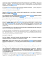
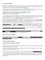
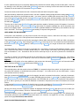
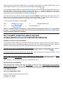
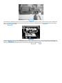
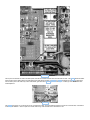
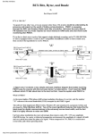
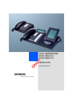
PACKET USERS NOTEBOOK
CQ MAGAZINE March 2K
by
Buck Rogers K4ABT
GOOD COMMUNICATIONS EQUAL EMERGENCY PREPAREDNESS, but there's a lot more to making sure one is
prepared for the inevitable.
Having plenty of food, water, and the essentials of life available are but the beginning of being prepared for disaster
related emergencies. There is another key element to the equation that now comes into play.
You will soon notice that I'm building this months Packet Users Notebook around a topic that varies from the subject of
Packet Radio or Digital communications. In a sense, this is true, however, after reading this months installation in your
Packet Users Notebook, you find this column is also worthy of being placed into your notebook.
AS SPRING APPROACHES, SO DOES………:
Spring will soon be here with a lot of new vegetation in bloom, but along with the good things come the unpredictable
springtime weather. Our topic for this spring is to be prepared with our emergency communications equipment, be it
digital data or voice. Having said that, let's talk about the project we are about undertake.
Operating 6 meter voice FM is one means to establish good communications. In addition, there are many 6 meter voice
repeaters now in operation.
What…? Huh? You mean there's repeaters on 6 meters….? Yes toto, there is a band that some of us enjoy, but don't
shout about. Six meters is one of the best bands for good, long, ground wave communications, and it is also one of the
best bands where we can experience frequent band openings.
SIX METER PROPAGATION:
I've been using six meters for more than 50 years. When 50.4 MHz was the only crystal that many of use owned
(remember the FT-243 encased rock), there I was. The old two element, bamboo, cubical quad, was my gateway into a
fraternity that still exists. At first it was the 2E26, then came a more compact version of low-end VHF tube, called the
5763. Don't ask me how it got its number… just trust me. I think the HEATH company at Benton Harbor, Michigan gave it
a good workout in their "sixer," commonly referred to in those days as the "Benton Harbor, Lunchbox."
Later I obtained a GE tube labeled as "6146." This is when my 2E26 at 15 to 20 watts was replaced with the 6146 to
give me twice that power. Well OK, there was a couple of minor changes that I had to make to the 2E26 cathode circuit,
to enable the 6146 to draw more current. The first mod was to change the three, parallel 330 ohm resistors to a single
47 ohm, 2 watt resistor.
It didn't take me long to realize that I also needed more current to support the added power output. Matter of fact, as a
young ham I learned a lot of real-time theory from that old 6 meter rig.
Before we move into to the crux of this months topic, I should make mention of the 6 meter converter that we had ahead
of our 3 to 30 MHz receivers.
Many a Hammarlund HQ-129, Hallicrafter S38, S40, and National receivers had a converter attached to them to make
them receive the first of the VHF ham bands.
I remember my first Hallicrafter S53 receiver. Now this was the next step in my learning curve that taught me; "All that
glitters, is not gold." I had somehow convinced myself that if purchased a communications receiver already had the six
meter band built in, that I'd be in "fat city." NOT SO; This turkey was as deaf as a doorknob. At best it was good for
local communications on 6 meters, but that was it! The receive RF amplifier in this beast (if there was one) for the 6
meter band, was, at best, poor to fair.
It took about three days for me to stop bragging about having a real 6 meter receiver, and drag out my old (6AK5 6SN7.. later to become a 6D5 NuVistor and a 12AT7), 6 meter converter (that output its six meter signal at 7 MHz), and
attach it between the Hallicrafter S53 antenna terminals and the six meter antenna.
BACK TO THE FUTURE:
Oh, but how times have changed! That was in the days of AM, remember Amplitude Modulation, now commonly called
"ancient modulation."
We still have the good qualities of that band, but we also have the good fortune to have much better and improved radios
to cover this almost forgotten band. It may be almost forgotten by some, but very much remembered by some of us who
enjoy the likes of a good rag-chew.
ENTER, THE LONG RANGR:
No, I did not misspell either of the last two words in the sub-heading above. Typically, watt for watt, the 6 meter FM
transceiver with a comparable antenna will communicate over a distance that is almost half again as far as the same
power at two meters will reach. There are several tables in many radio publications that will support what I've just
written. Having said that, I must explain why more public safety and public service groups no longer use the low VHF
bands for their communications medium.
Low band VHF as it is known, is more susceptible to sunspot activity. Out of each eleven (11) year sunspot cycle, about
5 to 7 years are destined to be cluttered with heavy, distant traffic. DX stations (1000, 2000, and sometimes, more than
3000 miles away), are received as good, and often better, than stations that are 20 to 30 miles away. Therein lies the
problem for the public safety and public service user.
This is why most law enforcement, public service, and other commercial radio users of these bands have moved away
from the clutter of "low-band" VHF and into the 800 and 900 MHz frequencies, using various coded and encoded
encryption formats.
As the commercial radio users move away from the low VHF bands in favor of the more stable communication
frequencies, we find that more and more of these radios are coming into the amateur radio market place. One such
market place is the local ham fest and Ham Club flea markets. One sure market place is at the Dayton or Shelby
hamfest. Since the Dayton HamVention is only a couple of months away, keep these issues of CQ Magazine in a safe
place……… You're gonna need them when you return from Dayton.
In the two-way communications industry we refer to the commercial low band and two meter VHF band as "conventional"
two way radio bands.
One of the radios (transceivers) appearing in the surplus of ham fest market place is the GE (ComNet-Ericsson)
RANGR™.
WHAT'S IN A MODEL NUMBER:
Our topic this month is built around the low band (Hi split) GE RANGR™. For our reference, we'll call it the model 138-B.
There are several others in this family of low-band RANGR's, and for the record, I'll mention them so that you are aware
of which is best for our 6 meter FM project.
There are the 162 and 169 A and B versions which we will NOT discuss. Then there is the more versatile 138 series.
The model 138-A is the low split 29 to 42 MHz, 60 watt version, and the 139-A low-split, (29-42) 110 watt version.
The RANGR model 138-A and 139-A make good 10 meter FM transceivers, however, this column will be referencing the
GE RANGR models 138-B (60 watt) and 139-B (110 watt) 35 to 50 MHz versions.
A PICTURE IS WORTH TEN THOUSAND WORDS:
To save a lot of reading and make this project easier for you, I'm building the remainder of this months column using
several photos and drawings in lieu of confusing you with a wordy document.
If you just happen to have a GE Communications LBI-31619-D or similar revision, you may wish to use it as an adjunct
to the items where we make changes in the GE RANGR 138-B.
I'll give you the "cooks" view of the finished control circuit before we begin the rest of the modification. It will be in the
form of a pictorial diagram. Sort of a duplication of terms, but after you look at the diagram, you'll better understand my
description. The drawing at figure one, I created using AutoCAD 14, and will explain why I used component symbols
integrated into the pictorial drawing.
As you study figure 1, you'll find there is a wealth of information embedded in the drawing. By carefully going over the
drawing, you'll find it easier to understand the photos that follow.
ALWAYS TEST BEFORE YOU BEGIN MODIFYING:
Connect the RANGR to the control head and cable it to the dummy load and power source. The tests and mods will
require that you have either a 20 Ampere, 13 volt DC supply for the model 138-B, or a 30 ampere, 13 volt DC supply
available for the model 139-B GE RANGR.
If you don't have the control head and cable harness for the RANGR, then take the RANGR by your friendly GE Service
Shop and ask them to give it a quick test using their RANGR test set.
Before we get to deep into this project, and while you are testing the RANGR to make sure it is good working condition,
go to the RF PA section and use RV1 to reduce the power level to around 20 to 30 watts. This will make more of sense
later when you are testing the transmit and setting the transmit VCO.
Once you are sure your low band, high split RANGR is working OK, then go ahead and build the control head as
described in figure one. Photo three is a shot of the condensed control head built according to the drawing at figure
one. This view may appear obscured a bit, because I apply a generous portion of hot-glue, or RTV to provide some
tensile strength to the small wires. The mini-control head is built into a plastic, RadioShack project enclosure box, part
number 270-1801.
The wire size and length is not etched in stone, however, it is good to have an idea what kind of wire size and type to use
for the control head construction. I used stranded, insulated, and tinned wire similar to #20 or #22 AWG. The length of
each wire in the control head was approximately 6 inches.
To make all the mini-control head connections easy, I pre-solder-tinned all the pins of J-801 that were to be used, and I
pre-tinned all the wire leads. In every case, I only cleared about one-sixteenth to one-eighth inch insulation from each
wire. Make all the connections to the mini-control head first. Double check all connections and insure that each
connection follows the drawing when the interface is complete.
BUILDING THE BIT_BUCKET:
Compile a list of the most used 6 meter frequencies in your area. Ask the local hams for the input and output frequencies
of the local repeaters. Be sure you include the local simplex frequencies. Most of all, be certain to include the
nationwide call frequency of 52.525 as one of the frequencies in your listing.
PLEASE NOTE: This next section applies only after you have programmed the RANGR, or had the 2212 EEPROM
programmed by someone. Many of us use the GE suitcase programmer, and others use the GE TQ-3330 programmer.
Many ComNET-Ericsson (GE) two-way service shops will have the latter, and will program the 16 channels into the 2212
EEPROM for a small fee.
There are other programmers, and one is made by Niles Radio company. I don't have any information to support the
Niles Programmer moving these radios into the Amateur bands. There is a disclaimer in the Niles software that states
that the programmer may not support amateur frequencies. You can visit their site at; http://www.nilesradio.com.
There is another site that is supported by my friend, Gary Marsh (VO1CPU) which may be of help to you. When making
your 2212 EEPROM for some GE two-way radios, Go to; http://home.thezone.net/~marsh/. Gary is always looking
for good data to support his EEPROM programmer projects. If you have supporting information that he might use, Email
Gary at: [email protected].
Important note; It is well known that when configuring the frequency list into the RANGR and DELTA EEPROM (2212),
the <ENTER> key will cause the programmer to display "OUT OF RANGE." When using the suitcase programmer, use
the "insert" key. When using the TQ-3330 RANGR and DELTA PC programmer, then use a "Ctrl-E" instead of the
<ENTER> key. This technique will force the programmer to allow the entry of Amateur band frequencies.
ENTER, THE CAN OPENER:
First of all you must get into the RANGR, and the rest is easy. Well, so it will be, after you're finished. As soon as you
get the Torx screws out of the top and bottom covers of the RANGR, remove the lock. Aww.. It's a piece of cake. I use
long nose pliers to remove the large nut that secures the lock. (see photo 1).
You will need several Torx screw driver blades from type 10 to type 40. Most WalMart, K-Mart, Lowe's, Big Lots, Sears
(CraftsMan) and most definitely, RadioShack stores carry an assortment of TORX screw drivers.
MODIFICATION OF THE LOBAND, HIGH-SPLIT RANGR FOR 6 METER FM (VOICE):
TRANSMIT VCO SETUP (LOCK) PROCEDURE:
If you are referencing some of the information from LBI-31619-D or the synthesizer maintenance manual, you'll find this
phrase somewhere in the text… "The synthesizer is factory aligned and should not require further adjustment." Yeah,
right! that only applies when using the GE RANGR in conventional commercial service, as built.
The next phrase applies more appropriately to our modification or when we attempt to move the low-band, high-split
outside the frequency(s) that it was intended for. READ ON… "Should it become necessary to adjust the synthesizer
please refer to the Maintenance Manual LBI-31714 and the "Frequency Synthesizer" section". This will familiarize you
with the operation of the VCO's and make the Alignment Procedure more understandable.
The label on the cover of the Synthesizer must be removed, or go ahead and poke hole in it as I've shown in these hole
locations are shown in Figure 2 and photo 4. There are holes in the casting below the label that allow you to access
the adjustable components, through the existing holes in the shield. Again, these hole locations are shown in photo four.
Select highest frequency transmit channel in the split (50 MHz). With a 50 ohm (200 watt) load on The antenna
connector J3, key the radio.
Adjust CV202 until the lock detector indicator CD7l0 goes out. Monitor TP201 with a digital voltmeter and adjust
CV202 for a reading of 7.0 +0.5 VDC for the high split (50 MHz) board. Check that LED CD710 remains out.
FEEL THE HEAT !! OK, then unkey the radio, as in .. RELEASE THE MIC PTT !!
RECEIVE VCO SETUP PROCEDURE
Select highest receive channel in the split as in Step 1 (release PTT switch). Adjust CV201 until lock detector
indicator CD710 goes out. Monitor TP201 with a digital voltmeter and adjust CV201 for a reading of 7.5
+0.1VDC. Make sure that CD710 remains out. Select each receive and transmit channel. Voltage at TP201 should be
between 3.5 and 7.5 VDC.
OSCILLATOR FREQUENCY SETUP
Monitor TX injection at J207 and Rx injection at J209.
Tx injection -3 to +6 dBm Rx injection -3 to +6 dBm
This step assumes the frequency is measured when the transmitter is first keyed. If delayed, the rapidly rising ambient
temperature must be taken into consideration.
Press the PTT switch while monitoring the Tx injection frequency at J207. Adjust FREQ TRIM Control on VC-TGXO for
the assigned channel frequency within +0.5 ppm.
Note: ASSUMING you've correctly set the "Freq Trim;" The receiver injection frequency will automatically be correct.
If you don't have an IFR 1200S or IFR 120B communications analyzer sitt'n around, then a receiver or scanner that
covers 50 to 54 MHz is always a good test monitor to have at your work station. "Work-Station?" you know, that's the
new politically correct way of saying; "work bench." Another item that will help make the modification easier is an RF
frequency counter.
A more important service tool is the handy-dandy dummy load that we all have setting around the ham shack. Since we
are working on the 138-B and 139-B model RANGRs, let's be sure our dummy load and watt meter will handle at least
150 watts, for the low band VHF frequencies through six meters.
Connect the leads control head to the radio. Connect the radio and head to the power supply.
Have the drill handy, loaded with a quarter-inch bit, one that is capable of drilling through aluminum casting (see photo 2).
Carefully make the hole for the Microphone cable. You have a choice for installing the access holes for the 12 volt DC
wire into the RANGR. I drilled the front of the RANGR near the Mic entry point, but later decided to enter the DC feed at
the back of the RANGR. I made the connections to the same points where the red and blue leads were removed within
the radio (see photo 5).
The wire size for the 60 watt RANGR DC power lead should be capable of delivering around 20 amperes of current at
13.6 volts during transmit. For the 60 watt RANGR, I used number 12, stranded, insulated wire, red for the positive, and
black for the negative leads. I use a bussman fuse holder (available WalMart or RadioShack), and installed a 20 amp
fuse in the holder. The 60 watt RANGR draws approximately 15 amperes during transmit.
HARD-WIRING THE MICROPHONE:
At this point in the modification, you may wish to include a mic connector, however, I didn't have one handy, so I opted to
hardwire the Mic directly to the J-801 printed circuit interface board (PCB).
This interface board is easily removed by first removing the ribbon cable connectors from J-802 and J-803 on the bottom
of the RANGR (see photo 4), then turning the RANGR over and removing the two Torx screws from the brass flashing
that secures J-801 (see photos 6 and 7). While you're looking at photo 6, you can get an idea of how I made the mic
connections.
The ferrite beads are optional, but just to be on the safe side, I used them to counter any RF feedback (squeals). In this
case, I didn't have the number 73 Amidon beads handy, so I used a couple of hex holed, ferrite tuning cores extracted
from an old trashed I F can. One bead is slid over the mic audio input at pin 9, and one is placed on the VOL/SQH HI
lead.
To tease your interest, the VOL/SQH HI lead can be traced back to the "System Control" PCB and to TP1. The reason I
make this point is to give you a "heads-up" to be sure you read next months Packet Users Notebook column in CQ
Magazine.
In that column, we'll perform a few minor additions to this mod and turn this same RANGR into a trio of Ham radio modes,
voice, 1200 baud AFSK Packet, and 9600 bauds DFSK Packet.
THE TRUTH IS IN THE TABLE:
The truth table shown with this months column as TABLE 1, is executed using a binary switch, be it thumb wheel, four of
six position DIP switches, or hexidecimal rotary switch, 0 through F. In no case do we try to use a BCD switch… unless
your head has need for an aching.
Although I've shown the RANGR truth table for 32 channels, the radio I converted for this article, I used only 16 channels.
Most RANGR radios that you find will have a spare EEPROM socket as shown in photo four. By adding another 2212
IC socket in the "spare" location, and popping another 2212 EEPROM with an additional 16 frequencies, and switching
pin 30 of J801 to ground, you can realize an additional 16 channels or frequencies for a total of 32 channels of six meter
FM fun.
In next months Packet Users Notebook, I'll describe how to include an interface for Packet use. This will require that you
include a few frequencies for Packet operation in your frequency list when flashing the EEPROM(s).
Not only will I show you how to include the interface for standard 1200 baud Packet, I'll also show you how to make your
RANGR operate all three modes; FM voice, 1200 baud AFSK Packet, and 9600 baud DFSK Packet.
The external speaker, shown in photo eight is an MFJ model MFJ-281 and comes equipped with a 3.5 millimeter plug.
The speaker jack that is mounted in the mini-control head is a 2 conductor, one eighth inch (3.5 mm), mini-phone jack,
(open circuit type) Radio Shack, P/N 274-251C.
NOW YOU HAVE BRAGG'N RIGHTS… YOU DID IT.
Now you can tell the world above 50 MHz that you are no longer "just the holder of an Amateur Radio license," you are
now a HAM radio operator. Now you can be proud of the finished product (see photo 8).
You've soldered, tweaked, toasted your finger at least once with the soldering iron, dropped a blob of hot solder in your
shoe, said "Oh darn" (yeah, right!.. sure you did), a couple of times, and ……… whoops, remember RV-1, don't forget to
return the power of your newly modified, 6 meter RANGR up to 50 watts (MOL). I know, it's a 60 watt radio, but since we
hams are prone to be a bit long winded, let's save the RF PA transistors.
Fifty watts will cover a lot of territory, and with a couple of stacked "ARROW" six meter beams, wow, there is a lot of real
estate to be covered. Besides, remember that 2E26 rig I told you about earlier; That was 15 watts, and even worse… it
was AM, and I could talk 50 to 200 miles on a clear night, using a 2 element bamboo quad.
In Y2K, we're having fun already, 73 de BucK4ABT
Email:
[email protected]
Visit:
www.PacketRadio.com
or
or
[email protected]
www.AmateuRadio.org
NOTE: T To activate channels 17 through 32, an 18 pin socket is required at the location in photo 4 designated
as "spare." A switched lead (spst) from pin 30 of J-801 to ground activates mode 2, thus enabling the channel
selector to select the additional 16 channels.
GE / Com-NET RANGR 050 LoBand, High Split
(50 MHz) MODIFICATION FOR 6 METER FM OPERATION
TRANSMIT VCO SETUP (LOCK) PROCEDURE:
The synthesizer is factory aligned and should not require further adjustment. Should it become necessary to adjust the
synthesizer please refer to the Maintenance Manual LBI-31714 and the "Frequency Synthesizer" section. These will
familiarize you with the operation of the VCO's and make the Alignment Procedure more understandable.
The label on the cover of the Synthesizer must be removed, or holes made in it to gain access to the adjustable
components, through the existing holes in the shield. These hole locations are shown in the attached photo .
Select highest frequency transmit channel in the split (50 MHz). With a 50 ohm load on The antenna connector J3, key
the radio.
Adjust CV202 until the lock detector indicator CD7l0 goes out. Monitor TP201 with a digital voltmeter and adjust
CV202 for a reading of 7.0 +0.1 VDC for the high split (50 MHz) board. Check that CD710 remains out.
FEEL THE HEAT !! OK, then unkey the radio, as in ..RELEASE THE PTT !!
RECEIVE VCO SETUP PROCEDURE
Select highest receive channel in the split as in Step 1 (release PTT switch). adjust CV201 until lock detector
indicator CD710 goes out. Monitor TP201 with a digital voltmeter and adjust CV201 for a reading of 7.5
+0.1VDC. Make sure that CD710 remains out. Select each receive and transmit channel. Voltage at TP201 should be
between 3.5 and 7.5 VDC.
OSCILLATOR FREQUENCY SETUP
Monitor TX injection at J207 and Rx injection at J209.
Tx injection -3 to +6 dBm
Rx injection -3 to +6 dBm
This step assumes the frequency is measured when the transmitter is first keyed. If delayed, the rapidly rising ambient
temperature must be taken into consideration.
Press the PTT switch while monitoring the Tx injection frequency at J207. Adjust FREQ TRIM Control on VC-TGXO for
the assigned channel frequency within +0.5 ppm.
Note: ASSUMING you've correctly set the "Freq Trim;" The receiver injection frequency will automatically be correct.
Buck K4ABT
FIGURE 1
Study this drawing, as you will soon discover, this diagram represents the heart of the project you are about to undertake. In addition, this illustration will
help you better understand my dialog throughout the text. As you study the above figure, you'll find there is a wealth of information embedded in the
drawing that relate to the photos that follow.
FIGURE 2
The label on the cover of the RANGR Synthesizer should be removed, or do as I did…. go ahead and poke holes in it as I've shown in the hole locations
shown above. There are holes in the casting below the label that allow access to the adjustable components. For a different view, see photo four.
PHOTO 1
As soon as you get the Torx screws out of the top and bottom covers of the RANGR, remove the lock. I use long nose pliers to remove the large nut that
secures the lock. Toss it, or use it for a paper weight. We won't need it again.
PHOTO 2
Have the drill handy, loaded with a quarter-inch bit, one that is capable of drilling through aluminum casting. Carefully make the hole for the Microphone
cable. You have a choice for drilling the access holes for the 12 volt DC power wires. I drilled the front of the RANGR for the Mic entry point, and the
back of the RANGR for the DC leads.
PHOTO
3
The mini-control head is built into a plastic, RadioShack project enclosure box, part number 270-1801. The mini control head is built as detailed in the
schematic at figure one. The above view is a bit obscured because I apply a generous portion of hot-glue, or RTV to provide some tensile strength to the
small wires. Hot Glue is also used to attach the mini-control to the front of the RANGR as shown at photo 8.
PHOTO
4
The interface board is the small PCB where J802 and J803 are connected. It can be removed by first removing the ribbon cable connectors from J-802
and J-803 shown above, then turning the RANGR over and removing the two Torx screws from the brass flashing that secures J-801. Notice also the
location of the "spare" IC socket. For more about the IC socket, see text and "truth table" at TABLE 1.
PHOTO
5
The DC power connections are made to the same points where the red and blue lead ends were removed within the radio. This photo illustrates the solder
bond connection of the negative lead to the brass flashing (see small square at bottom of photo). This photo also displays the microphone cable routing
and connection points. Mic cable entry hole is at the bottom, right of the above photo. Yep, I love that hot glue. Hot Glue gun from WalMart Arts and
Crafts department.
PHOTO 6
The photo above will give you an idea of how the mic connections are made. The ferrite beads are optional, but just to be on the safe side, I used them to
counter any RF feedback. I used a couple of hex holed, ferrite tuning cores extracted from an old trashed I F can.
PHOTO
7
This photo will provide you with the pin layout of J-801, so the mini-control head connections can be easier to locate. To make soldering the connections
easier, I pre-tinned all the pins of J-801 that were to be used, and pre-tinned the ends of all wires associated with the mini-control head. I cleared about
one-sixteenth to one-eighth inch insulation from each wire. Make all the connections to the mini-control head first. Double check all connections and
insure that each connection follows the drawing when the interface is complete.
PHOTO
8
You did it! Now you've earned the bragg'n rights, there's the finished product. You've soldered, tweaked, toasted your finger at least once with the
soldering iron, dropped a blob of hot solder in your shoe, said "Oh darn" (yeah, right!.. sure you did), at least twice. Now let's go have fun above 50 MHz.
Having Fun at 6 meters FM, PSK31, SSTV, and Packet!111 all on this Rangr!
73 de Buck Rogers K4ABT
Visit: www.BUXCOMM.com/catalog Order Toll Free: 1 800 726 2919 or 1 866 300 1969, Monday > Friday 9am to 4pm EST