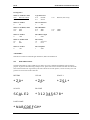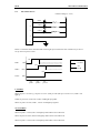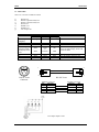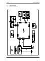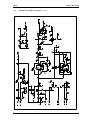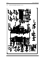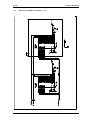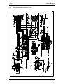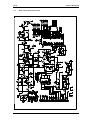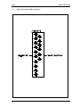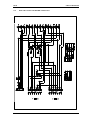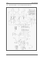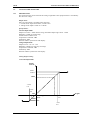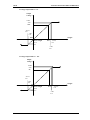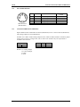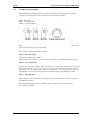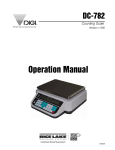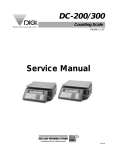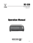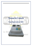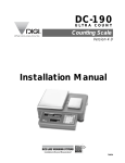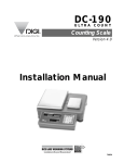
1
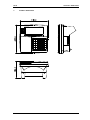
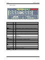
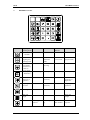
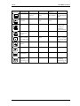
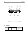
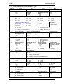
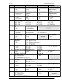
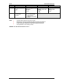
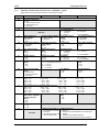
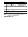
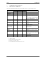
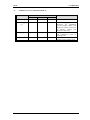
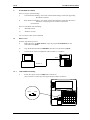
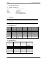
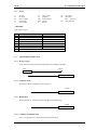
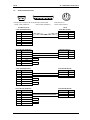
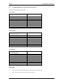
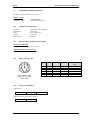
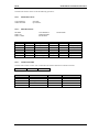
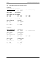
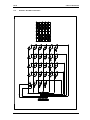
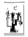
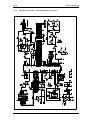
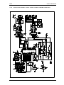
DI-80
Indicator
When Accuracy Counts
Service Manual
75591
DI 80
1.
GENERAL SPECIFICATION
GENERAL SPECIFICATION
Model
:
DI 80
Dimension
:
255 (L) X 240 (W) X 146 (H)
Number Of Loadcells
:
max 2 x External Platform or
max 8 x Loadcells in parallel configuration (350 ohm type)
(6-wires remote sensing available)
Input Sensitivity
:
0.4 to 4 mV/V
(12 V excitation)
Type Of Display
:
LCD with CCFL back-light
(Colour weight checker bar on LCD)
Display Resolution
:
1 / 2,500 ; 1 / 5,000 ; 1 / 10,000
Counting Resolution
:
1 / 500,000
Keyboard
:
Mechanical key switch
Memory
:
Standard 128K bytes ( approx. 1000 items ) ;
Expandable to max 256K bytes ( approx. 2000 items )
Set Point Output
:
max. 4 set points (Open Collector type)
Interface
Power Source
:
:
ii)
iii)
iv)
vi)
i)
RS232C, Set point (Standard)
Thermal Printer (Optional, OP1)
Line Printer (Optional, OP2)
RS232C with RS485 (Optional, OP3)
Analogue output (Optional, OP4)
i)
6 x D size battery
(Rechargeable type accepted; rechargeable circuit in-built)
AC/ DC adapter DC 9 ~ 12 V / 1.5A
ii)
Operating Temperature
:
-10°C ~ 40°C (14°F ~ 104°F)
Operating Humidity
:
15% ~ 85%
External Device
:
i)
ii)
iii)
Barcode scanner (RS232C)
Label Printer COSTAR SE 250
Thermal Printer ELTRON LP 2622
1
DI 80
2.
OVERALL DIMENSION
OVERALL DIMENSION
2
DI 80
3.
DISPLAY LAYOUT
DISPLAY LAYOUT
Segment Name
Main DIsplay
Pcs
kg
oz
g
lb
dwt
sub-1 display
Label
-
sub-2 display
-
à0ß
B/G
à Tß
NET
~
+ 2
INSUFF indicator
RECOM indicator
IN indicator
OUT indicator
Pcs
HOLD indicator
Pcs
MEMORY
indicator
PROG indicator
SCALE 1 indicator
SCALE 2 indicator
Pcs
L1
L2
L3
L4
L5
L6
L7
L8
L9
Functions
ON when Net weight is zero
ON when displaying gross weight
ON when weight is tared
ON when main display is showing Net Weight
ON when weight is stable
ON when battery voltage run low
To display weight , quantity, etc depending on the mode of operation
ON when main display is showing Quantity
ON when main display is showing Weight in kg
ON when main display is showing Weight in oz
ON when main display is showing Weight in g
ON when main display is showing Weight in dwt
ON when main display is showing Weight in dwt
Display Total weight, Unit weight, or PLU name depending on mode
operation
Display Unit weight , Quantity, setpoint, or PLU name depending on
mode operation
ON when sub-1 display is showing total weight
ON when net weight is below a specific percentage of capacity weight
ON when unit weight re-computing is possible
ON when inventory IN
ON when inventory OUT
ON when sub-1 display is showing unit weight
ON when holding function is enable
ON when sub-2 display is showing unit weight
ON when quantity accumulated overflow or memory overflow
L10
L11
L12
L13
ON when user is in programming mode
ON when scale 1 is selected
ON when scale 2 is selected
ON when sub-2 display is showing quantity
3
DI 80
4.
KEYSHEET LAYOUT
KEYSHEET LAYOUT
Key Name
Weighing /
Counting mode
Self Test
Calibration
SPEC141 /
SPEC142
PROG Mode
ON/OFF
Switch between
weighing and
counting mode
Exit from
calibration
mode
Rezero DI-80
and combine
with other key
to enter to
various mode
Clear key entry
or RAM data
Perform
rezeroing
Clear message
Clear key entry
Exit from
service mode
Exit from
program mode
Rezero
Clear key entry
Clear key entry
Perform onetouch tare or
digital tare
Increase
sensitivity
Perform onetouch tare or
digital tare
Sampling
operation
Reduce
sensitivity
Sampling
operation
Switching scale
Switching scale
Enter unit
weight
Enter unit
weight
Accumulation
Select type of
self test
Shift zero point Increment
up
SPEC number
4
Enter PLU
setpoint
DI 80
Key Name
KEYSHEET LAYOUT
Weighing /
Self Test
Counting mode
Reduction
Select type of
self test
SPEC141 /
SPEC142
Shift zero point Decrement
down
SPEC number
Printing
Operation
Span weight
entry
Perform test
Calibration
Calling out
PLU
Save SPEC
setting
PROG Mode
Enter Part No
or date and time
entry
Save data
Enter PLU
Name or call
out PLU or
check PLU
code in memory
Switch between
Net and Gross
display
Enter Decimal
point or switch
to Teraoka code
entry
Enter general
setpoint
Enter Decimal
point
Enter Decimal
point or switch
to Teraoka code
entry
Line feed
Enable/ disable
hold function
Provide unit
switching
between kg / lb
or oz / g / dwt
Provide unit
switching
between kg / lb
or oz / g / dwt
5
DI 80
INITIAL SETUP
5.
INITIAL SET UP
5.1
LOCATION OF CONNECTOR AND SWITCH
DC Adapter
Connector
SIO 1
(RS232C)
SIO 3
(RS485)
Setpoint
Scale 1
Scale 2
SIO 2
(RS232C)
Span Switch
(Please use a nonconductive material to
poke the span switch)
Back of DI 80
5.2
MEMORY CLEAR
OPERATION
[REZERO] +
[MODE] key
[REZERO]
+ [.][.][0]
[CLEAR]
Main (W)
ProG
DISPLAY
Sub-1(UW)
PLU
ALL
ProG
PLU
REMARKS
Sub-2 (Q)
Count
10
CLEAR
Count
6
Go to Program mode
To memory clear mode.
0 Delete all memory.
DI 80
SOFTWARE SETTING
6.
SOFTWARE SETTING
6.1
CUSTOMER SPEC SETTING
OPERATION
[REZERO]+
[1][4][1]
[+]
Main(W)
0.000
SPC00
DISPLAY
Sub-1(UW)
0
SPC01
REMARKS
Sub-2(Q)
0
0000
0000
[1][0][1][1]
SPC01
[+]
[-]
SPC02
SPC01
[1][1][1][1]
[C]
[*]
SPC01
SPC01
PROG
1111
1011
1011
C 00
[MODE]
0.0000
0
0
6.2
1011
0000
0000
1011
Weighing mode.
Customer SPEC mode.
Increases to the next SPEC number
and also stores temporarily the SPEC
data in the RAM location.
The Sub-1 section will display the
keyed in data.
Increases to the next SPEC number.
Decreases to the previous SPEC
number.
Enter new data.
Clear the keyed in data on Sub-1.
Store all SPEC values to the
EEPROM and exits from the SPEC
setting mode.
Press [MODE] key to escape from
Maintenance mode to weighing
mode.
WEIGHT AND MEASURE SPEC SETTING
OPERATION
Main(W)
S-On
DISPLAY
Sub-1(UW)
REMARKS
Sub-2(Q)
[REZERO] +
[1][4][2]
[+]
SPC20
0000
SPC21
0000
[1][0][1][1]
SPC21
[+]
[-]
SPC22
SPC21
[1][1][1][1]
[C]
[*]
SPC21
SPC21
PROG
[MODE]
S-On
Press the SPAN
SWITCH.
0.0000
1011
0000
0000
1011
1111
PLU
1011
1011
Count 0
0
0
7
Depress the SPAN SWITCH. The SOn message comes on.
Weigh & Measure SPEC mode.
Increases to the next SPEC number
and also stores temporarily the SPEC
data in the RAM location.
The Sub-1 section will display the
new keyed in data.
Increases to the next SPEC number.
Decreases to the previous SPEC
number.
Enter new data.
Clear the keyed in data on Sub-1.
Store all SPEC values to the
EEPROM and exits from the SPEC
setting mo de.
Press [MODE] key to escape from
Spec Setting mode. The display
shows S-On indicating that the span
switch is ON.
Depressing the Span Switch switches
to the weighing mode.
DI 80
SOFTWARE SETTING
6.3
SPECIFICATION LIST (REVISION 10)
6.3.1
DI-80 SOFTWARE HISTORY
Revision
No.
0
1
2
3
4
5
6
7
8
9
10
Modification Details
First release.
Change calibration procedures
a. Add SPEC14 BIT2 for “Tare Printing for Build-in Printer”
b. Add SPEC15 BIT 2 for “Line Feed after Total Print”
c. Add SPEC02 BIT3-1 for “Buzzer on Delay Function”
d. Remove SPEC39 BIT3 for “Basic A/D Setup”
e. Remove SPEC39 BIT2 for “Type of Calibration”
Add SPEC19 BIT3 for “Print DIGI MATEX Footer on Label Printer SE250”
Add SPEC00 BIT1 for “Send Net and Tare Weight only in RS-232C Mode”
a. Add SPEC11 BIT0 for “Send LF for LX-Serial Line Printer”
b. Add SPEC12 BIT1 for “Item Count for Minus Key Operation”
c. Add new option on “Serial Line Printer” for SPEC08 BIT2-0
a. Change SPEC36 BIT3&2 to “Weight Data Update”
b. Change SPEC36 BIT1&0 to “WS Condition”
c. Change SPEC37 BIT3-1 to “Digital Filter Used”
d. Change SPEC37 BIT0 to “Digital Tare when Loaded”
e. Change SPEC38 BIT3-1 to “Digital Filter Level”
Add SPEC58 BIT2 for Negative Weight Operation”
Add SPEC24 BIT0 for “Tare Indication Method”
a. Add SPEC59 BIT3 for “LCD Type”
b. Add SPEC59 BIT2 for “Build-in Printer Type”
a. Add SPEC58 BIT1 for “Printing within SP1 and SP2”
b. Add SPEC58 BIT0 for “Out Set Point when Weight is stable”
8
Software
Version
V0.21
V0.42
V1.03
V1.06
V1.08
V1.12
V1.14
V1.16
V1.17
V1.18
V1.21
DI 80
6.3.2
SOFTWARE SETTING
CUSTOMER SPECIFICATION [REZERO] + [1][4][1]
SPEC NO.
BIT 3
BIT 2
0
U1 Version
0 : No
1 : Yes
1
Auto Power Off Function
0000 : Disable
0100 : 4 min
0001 : 1 min
0101 : 5 min
0010 : 2 min
0110 : 6 min
0011 : 3 min
0111 : 7 min
Buzzer on Delay Function (< Set Point 1)
2
Recall Last Zero on
Power Up
0 : Inhibit
1 : Allow
BIT 1
Send Net and Tare
Weight only in RS-232C
Mode
0 : No
1 : Yes
1000 : 8 min
1001 : 9 min
1010 : 10 min
1011 : 11 min
(effective when SPEC17 BIT2 = 1)
3
4
Sampling Time for Unit
Weight Calculation
0 : 10 times
1 : 5 times
Unit Weight Auto Recomputing
0 : No
1 : Yes
6
Display Accuracy of
Unit Weight
0 : No
1 : Yes
Clear All Input Key in
One Touch
0: Yes
1: No
7
Set Point Buzzer
1 : Yes
0 : No
SIO1 Connection
0 : No
1 : Yes
Set Point
Set Point Type
0 : Latch
00 : %Quantity
1 : No Latch
01 : %Weight
Type of Devices *2
000 : Barcode scanner *3
001 : PC
010 : LP2622 / LP2722 printer *4
011 : SE250 printer
100 : Serial line printer (net mode, KG operation)
101 ~ 111 : Not used
SIO1 Baud Rate
000 : 1200
011 : 9600
001 : 2400
100 : 19200
010 : 4800
101 : 38400
SIO1 Header Type *1
SIO1 Parity
0 : Code
00 : No
1 : Text
01 : Odd
9
10
11
12
Set Point Display
0 : No
1 : Yes
1100 : 12 min
1101 : 13 min
1110 : 14 min
1111 : 15 min
Inventory Display by
Gross Key
0 : Gross display
1 : No. of inventory
000 : No delay
011 : 3 sec
110 : 6 sec
001 : 1 sec
100 : 4 sec
111 : 7 sec
010 : 2 sec
101 : 5 sec
ID Code
Entry Part No.
00 : Not used
00 : 12 numeric number only
01 : 16 digits Teraoka code
01 : Not used
11 : 16 digits numeric number only
11 : 16 digits Teraoka code
10 : Not used
10 : Not used
Set New Item Code
Extent of Insufficient Samples
Negative Counting
during Normal Mode
00 : 0.1 %
0 : No
0 : Yes
01 : 0.2 %
1 : Yes
1 : No
10 : 0 %
5
8
BIT 0
SIO1 Data Length
0: 7 bits
1: 8 bits
SIO1 Send with Header
*1
0 : Yes
1 : No
SIO1 Mode of Operation *1
00 : Remote trigger
01 : Continuous mode
10 : Manual mode
11 : Continuous and manual mode
TTL Output
00 : Holding output (weight stable + Hold)
01 : Set point output
10 : Checker output
11 : Disable
9
Date Order
00 : Year, Month, Date
01 : Date, Month, Year
11 : Month, Date, Year
10 : Not used
RS-232C Continue
Sending Rate to PC
0 : High
1 : Low
Auto Shift to Next
Position after Two Keys
of Teraoka Code Entry
0 : No
1 : Yes
10 : Quantity
11 : Weight
110 ~ 111: Not used
10 : Not used
11 : Even
SIO1 Stop Bit
0 : 1 bit
1 : 2 bits
Send “LF” for LX Serial
Line Printer
0 : No
1 : Yes
Item Code for Minus
Key Operation
0 : Plus
1 : Minus
Unit Switching
0 : No
1 : Yes
DI 80
SPEC NO.
SOFTWARE SETTING
BIT 3
13
Build-in Printer
0 : No
1 : Yes
14
Character Key Entry
0 : Teraoka code
1 : ASCII code
15
16
17
18
19
50
51
52
53
54
55
56
57
BIT 2
Auto Print
0 : No
1 : Yes
BIT 1
Date and Time Print
0 : No
1 : Yes
BIT 0
Allow PLU Calling when
Memory Flag Set
0 : No
1 : Yes
Blank Line between
Each Item Printed
0 : No
1 : Yes
Type of Holding
0 : Normal
1 : Peak
Tare Printing for BuildPLU Name Print
in Printer
0 : No
0 : No
1 : Yes
1 : Yes
Item Type for Auto Print Line Feed after Total
Holding Function
0 : Single
Print
0 : No
1 : Accumulation
0 : No
1 : Yes
1 : Yes
LCD Back-light Auto Off Function
0000 : Always OFF
0100 : 4 min
1000 : 8 min
1100 : 12 min
0001 : 1 min
0101 : 5 min
1001 : 9 min
1101 : 13 min
0010 : 2 min
0110 : 6 min
1 010 : 10 min
1110 : 14 min
0011 : 3 min
0111 : 7 min
1011 : 11 min
1111 : Always ON
LCD Light Off when No
Buzzer On
AC
0 : When weight is within
0 : No
SP1and SP2
Not Used
1 : Yes
1 : When weight is
outside SP1 and SP2
Set Point TTL Output
Number of Set Points
0 : Active low
000 : 2 set points
010 : 4 set points
1 : Active high
001 : 3 set points
011 ~ 111 : Not used
Display “PLU not
Print DIGI Matex Footer
Print when [+] or [–]
found” Message
on Label Printer SE250
Key in Add Mode
0 : Yes
0 : Yes
Not Used
0 : Yes
1 : No
1 : No
1 : No
SIO2 Type of Device *2
0 0 0 : Barcode scanner *3
0 0 1 : PC
0 1 0 : LP2622 / LP2722 printer *4
0 1 1 : SE250 printer
100 ~ 111 : Not used
SIO2 Data Length
SIO2 Baud Rate
0 : 7 bits
000 : 1200
011 : 9600
1 : 8 bits
001 : 2400
100 : 19200
010 : 4800
101 : 38400
SIO2 Send with Header SIO2 Header Type *1
SIO2 Parity
*1
0 : Code
00 : No
0 : Yes
1 : Text
01 : Odd
1 : No
SIO2 Mode of Operation *1
SIO2 Stop Bit
00 : Remote trigger
0 : 1 bit
01 : Continuous mode
1 : 2 bits
10 : Manual mode
11 : Continuous and manual mode
SIO3 (RS-485)
SIO3 Type of Device *2
Connection
000 : Not used
0 : No
001 : PC
1 : Yes
010 ~ 111 : Not used
SIO3 Data Length
SIO3 Baud Rate
0 : 7 bits
000 : 1200
011 : 9600
1 : 8 bits
001 : 2400
100 : 19200
010 : 4800
101 : 38400
SIO 3 Send with Header SIO3 Header Type *1
SIO3 Parity
*1
0: Code
00 : No
0 : Yes
1: Text
01 : Odd
1 : No
SIO3 Mode of Operation *1
SIO3 Stop Bit
00 : Remote trigger
0 : 1 bit
01 : Continuous mode
1 : 2 bits
10 : Manual mode
11 : Continuous and manual mode
SIO2 (RS-232C)
Connection
0 : No
1 : Yes
10
101 ~ 111: Not used
10 : Not used
11 : Even
Not Used
110 ~ 111: Not used
10 : Not used
11 : Even
Not Used
DI 80
SPEC NO.
SOFTWARE SETTING
BIT 3
BIT 2
58
Analogue Output
1 : Yes
0 : No
Negative Weight
Operation *5
1 : Yes
0 : No
59
LCD Type
1 : Euro (new)
0 : Japan
Build-in Printer Type
1 : Line thermal head
printer (ALPS)
0 : Thermal head printer
(Seiko)
NOTE : *1
*2
*3
*4
*5
BIT 1
Printing Allow when
Weight is within SP1
and SP2
0 : No
1 : Yes
Ignored setting if device is barcode scanner.
Same device cannot be reselected in SPEC 08, SPEC 50, SPEC 54.
Only period (.) for decimal point is allowed for barcode scanning.
Free Formats are required to pre-load into LP2622 and LP2722
Not applicable for Auto Printing function.
REMARK: All “Not Used” BIT must be set to 0.
11
BIT 0
Output Set Point when
Weight stable
0 : Yes
1 : No
Not Used
DI 80
6.3.3
SOFTWARE SETTING
WEIGHT AND MEASURE SPECIFICATION [REZERO] + [1][4][2]
(Span Switch must be turned ON when accessing this mode)
SPEC NO.
BIT 3
20
Dual Range Operation
00 : No
01 : Dual range in gross
10 : Dual range in net
11 : No used
21 & 22
23
24
25
26
27
28
29
30
31
32
33
34
BIT 2
BIT 1
BIT 0
Not Used
Not Used
Zero Setting Range
00 : + Unlimited /
10 : ±10% FS
Not used
- 10% FS
01 : ± 2% FS
11 : Not available
Masked Display at
Display at Minus Weight Zero Lamp Lighting
Tare Indication Method
Minus Weight
0 : Minus display
Method
0 : Tare lamp
0 : Gross
1 : Masked
0 : Gross
1 : Net lamp
1 : Net
1 : Net
Scale Starting Method
IR Mode Protected by
Second Scale
Gross Mode Available
0 : Automatic
Span Switch
0 : No
0 : Yes
1 : Manual
0 : No
1 : Yes
1 : No
1 : Yes
Zero Tracking when
Weight Reset when
Initial Start Range
Tare
Tare
00 : + Unlimited /
10 : ± 10% FS
0 : Yes
0 : Yes
- 10% FS
1 : No
1 : No
01 : ± 2% FS
11 : Not available
Comma Display
Digital Tare Setting
Tare Range
0 : No
0 : No
00 : 100% FS
10 : < 5% FS
1 : Yes
1 : Yes
01 : < 50% FS
11 : Not available
Auto Tare Clear when
Actuation Weight Condition **1
Automatic Unit Weight
Rezero
00 : >= net 5d and gross 21d
Clear
0 : No
01 : >= net 1d
0 : No
1 : Yes
10 : >= net 5d
1 : Yes
11 : >= net 21d
Digital Tare Rounding
Tare Addition
Tare Subtraction
(Store)
0 : Yes
0 : Yes
Not Used
0 : Tare exactly
1 : No
1 : No
1 : Round to nearest
increment
Load Cell sensitivities Selection (mV/V) (Scale 1)
0000 : 4.00
0100 : 3.04
1000 : 2.08
1100 : 1.12
0001 : 3.76
0101 : 2.80
1001 : 1.84
1101 : 0.88
0010 : 3.52
0110 : 2.56
1010 : 1.60
1110 : 0.64
0011 : 3.28
0111 : 2.32
1011 : 1.36
1111 : 0.40
Load Cell Sensitivities Selection (mV/V) (Scale 2)
0000 : 4.00
0100 : 3.04
1000 : 2.08
1100 : 1.12
0001 : 3.76
0101 : 2.80
1001 : 1.84
1101 : 0.88
0010 : 3.52
0110 : 2.56
1010 : 1.60
1110 : 0.64
0011 : 3.28
0111 : 2.32
1011 : 1.36
1111 : 0.40
Calibration / Default
Auto Exit from Add
SPEC/ SPEC 142 Mode
Mode
Protected by Span
0 : No
Not Used
Not Used
Switch
1 : Yes
1 : No
0 : Yes
Over Weight Mask
Not Used
0 : + 1d
1 : + 9d
Load Cell Type (Scale 1) A/D Board (Scale 1)
0 : For standard / normal 00 : Normal
load cell
01 : Prevent from small vibration / fast change in
Not Used
1 : For abnormal load cell
display
with too large offset
10 : Prevent from medium vibration
11 : Prevent from large slow change in display
12
DI 80
SOFTWARE SETTING
SPEC NO.
BIT 3
35
Not Used
36
Weight Data Update
00 : 1 in 1 time
01 : 1 in 2 times
Digital Filter Used
000 : 1 times
001 : 2 times
010 : 4 times
Digital Filter Level
000 : Level 0
001 : Level 1
37
38
BIT 2
10 : 1 in 4 times
11 : 1 in 8 times
011 : 8 times
100 : 16 times
101 : 32 times
010 : Level 2
011 : Level 3
Not Used
**2
BIT 0
Load Cell Type (Scale 2)
0 : For standard / normal
load cell
1 : For abnormal load cell
with too large offset
39
NOTE : **1
Unit Weight
BIT 1
A/D Board (Scale 2)
00 : Normal
01 : Prevent from small vibration / fast change in
display
10 : Prevent from medium vibration
11 : Prevent from large slow change in display
Weight Stable Condition
00 : Loose
10 : Tight
01 : Normal
11 : Stringent
Digital Tare when
110 ~ 111 : Not used
Loaded
0 : Allow
1 : Inhibit
Stability Check when
100 ~ 111 : Not used
Changing Scale **2
0 : Yes
1 : No
Re-zero when Changing
Scale **2
0 : No
1 : Yes
Actuation weight condition is used for (a) Weight Check Output, (b) Holding Function, (c)
Clear, and (d) Auto Printing (Build-in Printer).
When SPEC39 BIT0 set to 0, then SPEC38 BIT0 must be 0.
REMARK: All “Not Used” BIT must be set to 0.
13
DI 80
CALIBRATION
7.
CALIBRATION (Version 0.42 and above)
7.1
ZERO AND SPAN CALIBRATION
Please turn on the SPAN SWITCH before proceed. (If SPEC 32 bit 3 is 1, ignore the span switch.)
Operation
[REZERO] +
[8][7][1][5]
[*]
[#]
Display
Main(W)
Sub-1(UW)
Sub-2(Q)
S-On
W
CAL
Select Unit
W
W
CAL
CAL
Increment
[0].[0][0][1]
[#]
W
CAL
Increment
Capacity
0.001
0
[6].[0][0][0]
W
CAL
Capacity
6.000
[#]
CAL
0
Remove
Weight
If using actual CAL
capacity weight
SP
Weight
6.000
Else enter
weight
calibration
[#]
SP
Weight
5.000
------Count
-------500000
the CAL
for
Ir
[MODE]
•
•
•
•
S-On
0.0000
Select Unit
0
0
Remarks
Turn on the span switch.
Go to calibration mode.
Select weight unit: kg, lb, oz, dwt, g
Enter the increment in step of 1, 2, 5
or 10.
For this exmple, we will use capacity
6kg and increment 0.001 using
display resolution 1/6000. *
Enter the increment 0.001
To enter the capacity weight of the
platform.
Enter the full capacity weight of the
platform.
Zero point calibration. Remove
weight from platform.
Span Calibration. Put full capacity
weight on platter.
Span Calibration for partial capacity
weight. Enter the weight to calibrate.
E.g. 5kg.
--------Span Calibrating.
745000
After a few seconds, you will see the
internal count at Sub-1 and A/D
count at Sub-2.
Back to Span On mode.
0 Poke the span switch to return to
weighing mode.
Calibration Setting
Eg 6kg with display resolution 1/6000
Increment = 6 * (1/600) = 0.001
The last digit of the increment must be in 1,2,5,10
14
DI 80
7.2
CALIBRATION
INTERNAL COUNT / AD COUNT DISPLAY
OPERATION
[REZERO]
Main(W)
88888
[REZERO][*][*]
[+]
DISPLAY
Sub-1(UW)
88888
Sub-2(Q)
888888
REMARKS
0
50000
[MODE]
PROG
PLU
Count 0
[MODE]
0.0000
0
0
15
Enter
[0][0][9]
while
depressing
the
[REZERO]
key.Unit Weight window will
display the Internal Count and
the Quantity window will
display the A/D count.
Press [MODE] key to escape
from maintenance mode to
weighing mode.
Depressing the Span Switch
switches to the weighing mode.
DI 80
8
FLASH DOWNLOADING
FLASH DOWNLOADING
There are 2 types of downloading:
i)
User Mode Downloading -- this mode of flash downloading is used when upgrading
the indicator software
ii)
Boot Mode Downloading -- this mode of flash downloading is used when the CPU is
brand new or flash program is lost due to unforeseen
circumstances.
There are 2 methods of downloading:
i)
MS DOS Version.
ii)
Windows Version.
User can choose either of the 2 methods.
8.1
DOS Version
Do these steps before proceed :
a)
Make a directory eg DI 80 on the PC. Copy the program FAST80.EXE onto the
created directory DI 80.
b)
Copy the DI 80 main software DI80.MOT (hex file) on to the directory DI 80.
c)
Connect DI 80 via SIO1 using RS232 cable to COM 1 or 2 of the PC.
SIO 1
COM 1 / 2
8.1.1
USER MODE Downloading
1)
Switch the option switch to USER mode on the DI 80.
(This switch is accessible by removing the printer module. See below)
BOOT
USER
16
DI 80
FLASH DOWNLOADING
2)
While pressing [REZERO] + [#] button together, press the [ON/OFF] button.
The following will be shown on the indicator screen :
3)
Click on the FAST80.EXE in the directory DI80.
The following will be shown on the monitor:
TERAOKA WEIGH SYSTEM
R&D Department
DI-80 Flash memory loading program V1.07 (Timing Updated)
Firmware Version :
Checksum :
Enter Com Number (Press ‘Enter’ for default COM 1) :
4)
Enter the COM number or just press ‘ENTER’ if using COM 1.
The following will be shown on the monitor :
TERAOKA WEIGH SYSTEM
R&D Department
DI-80 Flash memory loading program V1.07 (Timing Updated)
Firmware Version :
Checksum :
Press any key to Start Downloading
5)
Press any key on the keyboard when ready to download.
The following will be shown on the monitor :
TERAOKA WEIGH SYSTEM
R&D Department
DI-80 Flash memory loading program V1.07 (Timing Updated)
Firmware Version: 1.25
Checksum: 870
Getting Response from Scale …… Any key to terminate …...
17
DI 80
FLASH DOWNLOADING
6)
If software is being loaded into DI 80 previously, it will be erased.
The following will be shown on the monitor :
TERAOKA WEIGH SYSTEM
R&D Department
DI-80 Flash memory loading program V1.07 (Timing Updated)
Firmware Version: 1.25
Checksum: 870
Erasing Flash …… Please Wait ……
7)
After a few seconds, the control program will start to download.
The following will be shown on the monitor :
TERAOKA WEIGH SYSTEM
R&D Department
DI-80 Flash memory loading program V1.07 (Timing Updated)
Firmware Version: 1.25
Checksum: 870
Loading Control Program …… Any key to terminate
* Control program is a program to help the DI 80 to download the application
program.
8)
After the control program finish downloading, the application programme will start to
download.
The following will be shown on the monitor :
TERAOKA WEIGH SYSTEM
R&D Department
DI-80 Flash memory loading program V1.07 (Timing Updated)
Firmware Version: 1.25
Checksum: 870
Loading Application Programme …… Any key to terminate
20 lines output to DI-80
9)
The number of lines will be running until the end of line of the application program.
A transmission end message “Download Completed” will appear after the download is
finished.
10)
After the process had completed, turn “Off” then “On” the indicator to see that the
software version had been changed.
18
DI 80
8.1.2
FLASH DOWNLOADING
BOOT MODE Downloading
1)
2)
3)
8.2
Switch the option switch to BOOT mode on the DI 80 and turn “On” the power only.
Repeat step 3 to 9 of USER MODE Downloading.
After finish downloading, turn “Off” the power and switch the OPTION switch to USER
then turn “On” the power.
Window Version
Do these steps before proceed :
a)
Make a directory eg DI 80 on the PC. Copy the program FAST80w.EXE on to the
created directory DI 80.
8.2.1
b)
Copy the DI 80 main software DI80.MOT (hex file) on to the directory DI 80.
c)
Connect DI 80 via SIO1 using RS232 cable to COM 1 or 2 of the PC.
(See Diagram above on page 16).
USER MODE Downloading
1)
Switch the option switch to USER mode on the DI 80.
(This switch is accessible by removing the printer module. See above on page 16)
2)
While pressing [REZERO] + [#] button together, press the [ON/OFF] button.
The following will be shown on the indicator screen :
3)
Click on the FAST80w.EXE in the directory DI80.
The following will be shown on the monitor:
19
DI 80
8.2.2
FLASH DOWNLOADING
4)
Activate the download by clicking on the <Start Download> icon. The program will run
automatically by searching for the indicator software and detecting the connection with
the indicator and download the control program and the application program.
5)
After the process had completed, turn “Off” then “On” the indicator to see that the
software version has been changed.
BOOT MODE Downloading
1)
2)
3)
Switch the option switch to BOOT mode on the DI 80 and turn “On” the power only.
Repeat step 3 to 4 of USER MODE Downloading.
After finish downloading, turn “Off” the power and switch the OPTION switch to USER
then turn “On” the power.
20
DI 80
PC / PRINTER CONNECTION
9.
PC / PRINTER CONNECTION
9.1
GENERAL SPECIFICATION
Baud rate
Data length
Parity
Stop bit
Printer type
:
:
:
:
:
1200 / 2400 / 4800 / 9600 bps
7 bits / 8 bits
None / Odd / Even
1 bit / 2 bits
COSTAR LabelWriter SE 250
ELTRON Thermal printer LP2622
9.2
OUTPUT DATA FORMAT
a)
With Header
HEADER
b)
DATA
CR
HEADER
……….
CR
LF
DATA
CR
……….
CR
LF
Without Header
DATA
CR
9.2.1 HEADER WITH CODE
Header Code
ASCII Code
0
1
2
3
4
8
A
B
C
F
30
31
32
33
34
38
41
42
43
46
Data
Header Code
ASCII Code
G
H
I
K
M
N
V
Q
X
47
48
49
4B
4D
4E
56
51
58
Net weight
Unit weight
Quantity
ID code
Tare weight
Total weight
Gross weight
Status
Date and time
Set point 1
(Weight)
Data
Set point 1 (Qty)
Set point 2
Total quantity
Inventory
Parts no
Parts name
Scale no
Set point 3
Set point 4
9.2.2 HEADER WITH TITLE
Data
Title
Data
Net weight
Unit weight
Quantity
NET WEIGHT
UNIT WEIGHT
QUANTITY
Set point 2
Total weight
Total quantity
ID code
Tare weight
Gross weight
Status
Date and time
Set point 1
(Weight)
Set point 1 (Qty)
ID CODE
TARE
GROSS WEIGHT
STATUS
DATE & TIME
SET P1(W)
Inventory
Parts no
Parts name
Scale no
Set point 3
Set point 4
SET P1(Q)
21
Title
SET P2
TOTAL WEIGHT
TOTAL
QUANTITY
INVENTORY
PART NO
PART NAME
SCALE NO
SET P3
SET P4
DI 80
PC / PRINTER CONNECTION
9.3
DATA
i)
ii)
iii)
iv)
v)
ID code
Set point
Gross weight
Net weight
Unit weight
vi)
vii)
viii)
viiii)
x)
Tare weight
Quantity
Total quantity
Status *
Part no.
xi)
xii)
Inventory
Part name
xiii)
Scale no.
xiv) Date and time
* REMARK :
Status data as below :
Bit
0
1
2
3
4
5
6
7
9.4
If set to 1
If set to 0
Positive weight
Negative weight
Weight stable
Weight unstable
Output key in data
Others
Output by + key
Others
Output by – key
Others
Output by * key
Others
Output total
Others
Always set to “1”
TRANSMISSION PROTOCOL
9.4.1 Remote Trigger
Upon received of ENQ from host, DI-80 will send out weight information
Host
ENQ
DI-80
Data
9.4.2 Continuous mode
DI-80 will send out weight data at a fixed interval
DI-80
Data
9.4.3 Manual mode
DI-80 will send out weight data when user depress the PRINT key.
DI-80
Data
9.4.4 Continuous and Manual mode
This is a combination of continuous mode and manual mode.
22
DI 80
9.5
PC / PRINTER CONNECTION
WIRE CONFIGURATION
9 PIN D-SUB CONNECTOR 25 PIN D-SUB CONNECTOR
BACK VIEW (FEMALE)
BACK VIEW (FEMALE)
8 PIN DIN PLUG
BACK VIEW (MALE)
ELTRON LP2722
9 PIN D-SUB (FEMALE)
PIN
SIGNAL
3
TXD
2
RXD
5
GND
4
DTR
6
DSR
7
RTS
8
CTS
DI 80
8 PIN DIN (MALE)
SIGNAL
PIN
RXD
4
TXD
5
GND
2
25 PIN D-SUB (FEMALE)
PIN
SIGNAL
2
TXD
3
RXD
7
GND
4
RTS
5
CTS
6
DSR
20
DTR
8 PIN DIN (MALE)
SIGNAL
PIN
RXD
4
TXD
5
GND
2
9 PIN D-SUB (FEMALE)
PIN
SIGNAL
3
TXD
2
RXD
5
GND
4
DTR
6
DSR
7
RTS
8
CTS
9 PIN D-SUB (MALE)
SIGNAL
PIN
RXD
2
TXD
3
GND
5
25 PIN D-SUB (FEMALE)
PIN
SIGNAL
2
TXD
3
RXD
7
GND
4
RTS
5
CTS
6
DSR
20
DTR
9 PIN D-SUB (MALE)
SIGNAL
PIN
RXD
2
TXD
3
GND
5
23
DI 80
9.6
PC / PRINTER CONNECTION
PC / PRINTER RS232C CONNECTION SPEC SETTING
Setting on DI 80 under [Re-Zero]+[141] :
If using SIO 1 :
RS232 Continue Sending Rate To PC
(PC connection only)
Type Of Devices *
SIO 1 Connection
SIO 1 Baud Rate
SIO 1 Data Length
SIO 1 Parity
SIO 1 Send Header As **
SIO 1 Send With Header **
SIO 1 Stop Bits
SIO 1 Mode Of Operation **
SPEC 6 Bit 1
SPEC 8 Bit 0, 1 and 2
SPEC 8 Bit 3
SPEC 9 Bit 0, 1 and 2
SPEC 9 Bit 3
SPEC 10 Bit 0 and 1
SPEC 10 Bit 2
SPEC 10 Bit 3
SPEC 11 Bit 1
SPEC 11 Bit 2 and 3
If using SIO 2 :
RS232 Continue Sending Rate To PC
(PC connection only)
Type Of Devices *
SIO 2 Connection
SIO 2 Baud Rate
SIO 2 Data Length
SIO 2 Parity
SIO 2 Send Header As **
SIO 2 Send With Header **
SIO 2 Stop Bits
SIO 2 Mode Of Operation **
SPEC No. 6 Bit 1
SPEC No. 50 Bit 0, 1 and 2
SPEC No. 50 Bit 3
SPEC No. 51 Bit 0, 1 and 2
SPEC No. 51 Bit 3
SPEC No. 52 Bit 0 and 1
SPEC No. 52 Bit 2
SPEC No. 52 Bit 3
SPEC No. 53 Bit 1
SPEC No. 53 Bit 2 and 3
If using SIO 3 :
RS232 Continue Sending Rate To PC
(PC connection only)
Type Of Devices *
SIO 3 Connection (RS 485)
SIO 3 Baud Rate
SIO 3 Data Length
SIO 3 Parity
SIO 3 Send Header As **
SIO 3 Send With Header **
SIO 3 Stop Bits
SIO 3 Mode Of Operation **
SPEC No. 6 Bit 1
SPEC No. 54 Bit 0, 1 and 2
SPEC No. 54 Bit 3
SPEC No. 55 Bit 0, 1 and 2
SPEC No. 55 Bit 3
SPEC No. 56 Bit 0 and 1
SPEC No. 56 Bit 2
SPEC No. 56 Bit 3
SPEC No. 57 Bit 1
SPEC No. 57 Bit 2 and 3
REMARKS:
*
Same device cannot be reselected again in SPEC 08, SPEC 50 and SPEC 54
**
Ignore these SPEC setting if device is barcode scanner.
24
DI 80
9.7
PC / PRINTER CONNECTION
BUILT-IN PRINTER
Setting on DI 80 under Re-Zero+[141] :
Built-in Printer
Line Thermal Head Printer (ALPS)
Thermal Head Printer (Sieko)
Set SPEC 13 Bit 3 to 1
Set SPEC 59 Bit 2 to 1
Set SPEC 59 Bit 2 to 0
* Note :
For Line Thermal Head Printer, software needs to be at least V1.24
Printer Board Interface for Line Thermal Head Printer (ALPS) is TWB-02370-0
Printer Board Interface for Thermal Head Printer (Seiko) is TWB-02340-0
9.8
EXTERNAL PRINTER
DI 80 can connect with these external printer :
9.8.1 COSTAR SE 250
Setting on DI 80 :
Baud rate
Data length
Parity
Stop bit
Type of device
RS232 Output :
:
9600 bps
:
8 bits
:
None
:
1 bit
:
SE 250
By [ * ] , [ + ] and [ – ] key
9.8.2 ELTRON LP 2622
Setting on DI 80 :
Baud rate
Data length
Parity
Stop bit
Type of device
RS232 Output :
:
9600 bps
:
8 bits
:
None
:
1 bit
:
LP 2622
By [ * ] , [ + ] and [ – ] key
* Note :
DI 80 will download some label formats to LP 2622 when power up. Owing to this, LP 2622 should
connect to DI 80 when DI 80 power up. Also, make sure the printer has enough memory allocated for
Form memory (at least 3K). Please refer to the printer manual.
25
DI 80
10.
BARCODE SCANNER CONNECTION
BARCODE SCANNER CONNECTION
DI 80 can support these barcode scanners :
RS232C TYPE
Pen scanner
Handheld scanner
10.1
GENERAL SPECIFICATION
Baud rate
Data length
Parity
Stop bit
Barcode type
10.2
- ZEBEX ZB-800R
- PSC Quickscan scanner
:
:
:
:
:
1200 / 2400 / 4800 / 9600 bps
7 bits / 8 bits
None / Odd / Even
1 bit / 2 bits
CODE 39
DEFAULT SPEC OF BARCODE SCANNER
Pen Scanner, ZB-800R
9600 bps, 8 bits, None parity and 1 stop bit
Handheld Scanner, PSC Quickscan
9600 bps, 7 bits, None parity and 1 stop bit
10.3
PIN CONFIGURATION
PIN
SIGNAL
ZB-800R
Quickscan
2
4
5
6
7
8
GND
RXD
TXD
CTS
RTS
VCC
Yellow
Grey
Brown
White
Green
Red
Black
Orange
White
Blue
Yellow
Red
8 PIN DIN PLUG FOR
BARCODE SCANNER
(BACK VIEW)
10.4
INPUT DATA FORMAT
With Header
Header
Data
CR
Without header (Can scan ID Code only)
Data
CR
26
PSC QuickScan
6000
Black
Blue
Orange
Yellow (Not Used)
White (Not Used)
Red
DI 80
BARCODE SCANNER CONNECTION
The barcode scanner can be use in the following operation :
10.4.1
OPERATION Mode :
UNIT WEIGHT
TARE WEIGHT
10.4.2
ID CODE
QUANTITY
PROGRAM Mode :
ID CODE
PART NO.
PART NAME
Header Code
1
2
3
4
A
F
G
10.4.3
UNIT WEIGHT
TARE WEIGHT
SET POINTS
ASCII Code
31
32
33
34
41
46
47
Data
Unit weight
Quantity
ID code
Tare weight
Gross weight
Set point 1 (W)
Set point 1 (Q)
INVENTORY
Header Code
H
I
K
M
N
Q
X
ASCII Code
48
49
4B
4D
4E
51
58
Data
Set point 2
Total quantity
Inventory
Part no.
Part name
Set point 3
Set point 4
COMMAND CODE
The barcode scanner can also scan command to DI 80 but it must have a header Z in front.
Header : Z
Command
Z + Command
Z0
Z1
Z2
Z3
Z4
Function
Rezero
Print
Unit weight clear
Plus
Minus
CR
Z + Command
Z5
Z6
ZS1
ZS2
27
Function
Tare
Clear
Scale 1
Scale 2
DI 80
10.5
BARCODE SCANNER CONNECTION
BARCODE SCANNER CONNECTION SPEC SETTING
If using SIO 1 :
SPEC No. 8 Bit 0, 1 and 2 Type Of Devices *
000
Barcode scanner
010
LP 2622
001
PC
011
SE 250
SPEC No. 8 Bit 3
0
No
Ethernet (Not ready)
100
101
19200
38400
100
Ethernet (Not ready)
100
101
19200
38400
SIO 1 Connection
1
Yes
SPEC No. 9 Bit 0, 1 and 2 SIO 1 Baud Rate
000
1200
010
4800
001
2400
011
9600
SPEC No. 9 Bit 3
0
7 bits
100
SIO 1 Data Length
1
8 bits
SPEC No. 10 Bit 0 and 1
00
No
01
Odd
SIO 1 Parity
10
Not used
11
Even
SPEC No. 11 Bit 1
0
1 bit
SIO 1 Stop Bits
1
2 bits
If using SIO 2 :
SPEC No. 50 Bit 0, 1 and 2
000
Barcode scanner
001
PC
Type Of Devices *
010
LP 2622
011
SE 250
SPEC No. 50 Bit 3
0
No
SIO 2 Connection
1
Yes
SPEC No. 51 Bit 0, 1 and 2
000
1200
001
2400
SIO 2 Baud Rate
010
4800
011
9600
SPEC No. 51 Bit 3
0
7 bits
SIO 2 Data Length
1
8 bits
SPEC No. 52 Bit 0 and 1
00
No
01
Odd
SIO 2 Parity
10
Not used
11
Even
SPEC No. 53 Bit 1
0
1 bit
SIO 2 Stop Bits
1
2 bits
28
DI 80
BARCODE SCANNER CONNECTION
If using SIO 3 :
SPEC No. 54 Bit 0, 1 and 2
000
Barcode scanner
001
PC
Type Of Devices*
010
LP 2622
011
SE 250
SPEC No. 54 Bit 3
0
No
SIO 3 Connection
1
Yes
SPEC No. 55 Bit 0, 1 and 2
000
1200
001
2400
SIO 3 Baud Rate
010
4800
011
9600
SPEC No. 55 Bit 3
0
7 bits
SIO 3 Data Length
1
8 bits
SPEC No. 56 Bit 0 and 1
00
No
01
Odd
SIO 3 Parity
10
Not used
11
Even
SPEC No. 57 Bit 1
0
1 bit
SIO 3 Stop Bits
1
2 bits
100
Ethernet (Not ready)
100
101
19200
38400
* REMARKS :
Same device cannot be reselected again in SPEC 8, SPEC 50 and SPEC 54
10.6
BARCODE SAMPLE
The barcode formats is using CODE 39 type. Below are some command and data barcodes for testing
purpose. If generate barcode using word processor, please add * before and after the data to indicate the
start and end of barcode. If generate by barcode software or barcode printer, it is not necessary as it will
generate it own start and end of barcode.
REZERO
CLEAR
SCALE 1
*Z0*
Z1
*Z6*
Z6
*ZS1*
ZS1
SCALE 2
ID CODE
SCALE2
ZS2
*312345678*
312345678
PART NAME
*NABCDEFGH*
NABCDEFGH
29
DI 80
11.
SET POINT CONNECTION
SET POINT CONNECTION
There can 2, 3 or 4 set point output depend by SPEC. It need an external voltage (5 ~ 29 V) to drive the
set points.
11.1
PIN CONFIGURATION
PIN
1
2
3
4
5
6
7
8
SIGNAL
Set point 1
Set point 2
Set point 3
Set point 4
External voltage*
GND
8 Pin Mini DIN Plug
Front View
* External voltage is from the range 5 to 29 V DC.
11.2
SET POINT SPEC SETTING
SPEC No. 0 Bit 0
0
No
Set Point Display
1
SPEC No. 7 Bit 0 and 1
00
% Quantity
01
% Weight
Yes
Set Point Type
10
11
SPEC No. 7 Bit 2
0
Latch
Set Point Latch
SPEC No. 7 Bit 3
0
Yes
Set Point Buzzer
Quantity
Weight
1
No latch
1
No
SPEC No. 12 Bit 2 and 3
TTL Output
00
Holding output (WS+HOLD)
10
01
Set point output
11
Checker output
Disable
SPEC No. 17 Bit 2
0
When weight is within
SP1 and SP2
Buzzer On
1
When weight is outside
SP1 and SP2
SPEC No. 18 Bit 0, 1 and 2
000
2 set points
001
3 set points
Number Of Set Points
010
011~111
SPEC No. 18 Bit 3
0
Active low
Set Point TTL Output
1
Active high
30
4 set points
Not used
DI 80
11.3
SET POINT CONNECTION
SET POINT SET UP
External Voltage (5 ~ 29 V)
LED 1
1
LED 2
2
LED 3
3
7
8
Below is a chart that show when the LEDs will be light up in latch and no latch condition as per above
set up when set point is reach.
ON
LED 1
LATCH
OFF
ON
LED 2
NO
LATCH
OFF
ON
LED 3
OFF
Set
point 1
Set
point 2
Set
point 3
LATCHING
When set point 1 is reach e.g. set point 1 is set to 1,000 pcs and 1,000 pcs is reach or over, LED 1 will
light up.
When set point 2 is reach, LED 1 and 2 would light up together.
When set point 3 is reach, LED 1, 2 and 3 would light up together.
NO LATCHING
When set point 1 is reach, LED 1 will light up while LED 2 and 3 will be off.
When set point 2 is reach, LED 2 will light up while LED 1 and 3 will be off.
When set point 3 is reach, LED 3 will light up while LED 1 and 2 will be off.
31
DI 80
SELF TEST
12. SELF TEST
There are 7 self test available for DI-80:
a)
b)
c)
d)
e)
f)
g)
RS 232 test
RS 232 (optional board) test
RS 485 (optional board) test
Printer test
SRAM1 test
SRAM2 test
TTL output test
OPERATION
[REZERO] +
[0][8][9][3]
[+] or [-]
[*]
After testing is
completed, DI-80
will displayed test
result
[C]
[*]
Main (W)
Prog
DISPLAY
Sub-1(UW)
REMARKS
Sub-2 (Q)
At PROG mode.
SELF
SELF
PRINTER
PLEASE
TEST
WAIT
SELF
TEST
or
FOUND
OK
SELF
SELF
SELF
ProG
ERR
PRINTER
EXIT
PLU COUNT
TEST
SELF
6
Select the testing hardware.
To test the hardware selected.
The screen will display the result of
the test. It either display TEST OK
or FOUND ERR.
Go back to the self test mode.
Go to the display shown to exit.
8
1
8
1
RS232 Tester
Connector
RS 485 Tester
Modular Connector
PIN
SIGNAL
1
IN+
2
IN3
OUT+
4
OUT-
TTL output sample circuit
32
Modular Connector
SIGNAL
PIN
OUT+
3
OUT4
IN+
1
IN2
DI 80
CIRCUIT DIAGRAM
13.
CIRCUIT DIAGRAM
13.1
DI 80 BLOCK DIAGRAM
33
DI 80
13.2
CIRCUIT DIAGRAM
DI 80 MAIN BOARD TWB-02300-0 ( 1 of 4 )
34
DI 80
13.2
CIRCUIT DIAGRAM
DI 80 MAIN BOARD TWB-02300-0 ( 2 OF 4 )
35
DI 80
13.2
CIRCUIT DIAGRAM
DI 80 MAIN BOARD TWB-02300-0 ( 3 of 4 )
36
DI 80
13.2
CIRCUIT DIAGRAM
DI 80 MAIN BOARD TWB-0230-0 ( 4 of 4 )
37
DI 80
13.3
CIRCUIT DIAGRAM
DI 80 A/D BOARD TWB-02330-0
38
DI 80
13.4
CIRCUIT DIAGRAM
DI 80 A/D FILTER BOARD TWB-02290-0
39
DI 80
13.5
CIRCUIT DIAGRAM
DI 80 A/D CONNECTOR BOARD TWB-02360-0
40
DI 80
13.6
CIRCUIT DIAGRAM
DI 80 KEY BOARD TWB-02380-0
41
DI 80
13.7
CIRCUIT DIAGRAM
DI 80 CONNECTOR BOARD TWB-02310-0
42
DI 80
13.8a
CIRCUIT DIAGRAM
DI 80 OPTION BOARD 1 – PRINTER BOARD TWB-02340-0
43
DI 80
13.8b
CIRCUIT DIAGRAM
DI 80 OPTION BOARD 2 – RS232C / RS485 I NTERFACE BOARD TWB-02350-0
44
DI 80
13.8c
CIRCUIT DIAGRAM
DI 80 OPTION BOARD 3 – ANALOG INTERFACE BOARD TWB-02370-0
45
DI 80
ANALOG OUTPUT BOARD CALIBRATION
14.
ANALOG INTERFACE BOARD
14.1
SPECIFICATION
This option board is used to transmit the analog weight data to the equipment that is controlled by
DC current or voltage.
Output mode:
Only one output mode is available at the same time.
1. Current mode: output 4mA~20mA, current source
2. Voltage mode: output 0~5VDC or 0~10VDC
Specifications:
Current Output Mode:
Output Level: 4mA ~ 20mA effective range, maximum output range is 2mA ~ 22mA
Resolution: 1/2000 (or 0.01mA/step)
Load Resistance: 500Ω or less
Temperature Coefficient: TBD
Nonlinearity: TBD
Renewal of Data: Synchronous with display
Voltage Output Mode:
Output Level: 0 ~ 5V or 0 ~ 10V
Resolution: 1/2000 (or 2.5mV/step, 5mV/step)
Temperature Coefficient: TBD
Nonlinearity: TBD
Renewal of Data: Synchronous with display
Analog Output Scaling
1. Current Output Mode
Output
Current
22mA
21.6mA
20mA
-12.5%
F.S.
-10%
F.S.
4mA
Weight
Zero Weight
2.4mA
F.S.
+12.5%
F.S.
2mA
+10%
F.S.
46
DI 80
ANALOG OUTPUT BOARD CALIBRATION
2. Voltage Output Mode: 0 ~ 5V
Output
Voltage
5.00V
4.9V
4.5V
-12.5%
F.S.
-10%
F.S.
Weight
0.5V
F.S.
Zero Weight
+12.5%
F.S.
0.1V
0V
+10%
F.S.
3. Voltage Output Mode: 0 ~ 10V
Output
Voltage
10.00V
9.8V
9V
-12.5%
F.S.
-10%
F.S.
1V
Weight
F.S.
Zero Weight
0.2V
0V
+12.5%
F.S.
+10%
F.S.
47
DI 80
14.2
ANALOG OUTPUT BOARD CALIBRATION
PIN CONFIGURATION
5 PIN DIN PLUG
(BACK VIEW)
14.3
PIN
SIGNAL
REMARKS
1
2
3
4
5
CO+
COVO+
VO-
Current Output +
Current Output – (GND)
Voltage Output +
Voltage Output – (GND)
No Connection
PLUG WIRE
COLOR
RED
YELLOW
BLUE
PURPLE
ANALOG INTERFACE BOARD SETUP
Replace blank bracket or RS232/485 I/F Board (TWB-02350) next to connector board (TWB-02310)
with analog output I/F board (TWB-02370).
Set SPEC 58 is 1000 to enable Analog Output function, while set 0000 to disable it. Hardware jumper
setting selects current or voltage mode, refer to silk screen on PCB. Only one output mode is
available at the same time.
JP1
1-2
2-3
VO
CO
JP3
O
S
JP4
S
O
Remark: VO: Voltage Output
CO: Current Output
O: Open
S: Short
48
VOUT
0-5V
0-10V
DI 80
14.4
ANALOG OUTPUT BOARD CALIBRATION
CALIBRATION PROCEDURE
Analog output value should be 4mA at Zero Point and 20mA at Capacity Weight. If the output
values are not the appropriate value, adjust those by the following procedure.
ZERO – Rezeroing
SPAN1 – Fine adjustment
SPAN2 – Coarse adjustment
Before startup, precautions have to be taken to ensure all potentiometers are not overturned. After
the check has been done, proceed with setup.
The procedure can be accomplished as follows:
STEP 1 – Zero offset adjust
Load all zeros, then tune the “ZERO”.
For the voltage mode, adjust to 1V, while for the current mode, on the other hand, adjust to 4mA.
STEP 2 – Coarse adjustment
Load all ones, adjust the “SPAN2” which constitutes the varying of the operating range. Careful
tuning has to be taken, as it is very sensitive. It is termed as coarse adjustment because it varies a
wider range. For the voltage mode, adjust to approximately 8.99V for the 0-10V range and
approximately 4.2V for the 0-5V range. For the current mode, adjust to approximately 19.99mA.
STEP 3 – Fine adjustment
Adjust “SPAN1” which constitutes in fine adjustment to the actual full span. This has to be done
after adjusting “SPAN2”.
This adjustment algorithm is iterative, therefore, STEP1 to STEP3 has to be repeated until
convergence is obtained.
49
DI-80 Limited Warranty
Rice Lake Weighing Systems (RLWS) warrants that all RLWS equipment and systems properly installed by a
Distributor or Original Equipment Manufacturer (OEM) will operate per written specifications as confirmed
by the Distributor/OEM and accepted by RLWS. All systems and components are warranted against defects
in materials and workmanship for two (2) years.
RLWS warrants that the equipment sold hereunder will conform to the current written specifications
authorized by RLWS. RLWS warrants the equipment against faulty workmanship and defective materials. If
any equipment fails to conform to these warranties, RLWS will, at its option, repair or replace such goods
returned within the warranty period subject to the following conditions:
•
Upon discovery by Buyer of such nonconformity, RLWS will be given prompt written notice with a detailed explanation
of the alleged deficiencies.
•
Individual electronic components returned to RLWS for warranty purposes must be packaged to prevent electrostatic
discharge (ESD) damage in shipment. Packaging requirements are listed in a publication, “Protecting Your Components
From Static Damage in Shipment,” available from RLWS Equipment Return Department.
•
Examination of such equipment by RLWS confirms that the nonconformity actually exists, and was not caused by
accident, misuse, neglect, alteration, improper installation, improper repair or improper testing; RLWS shall be the sole
judge of all alleged non-conformities.
•
Such equipment has not been modified, altered, or changed by any person other than RLWS or its duly authorized repair
agents.
•
RLWS will have a reasonable time to repair or replace the defective equipment. Buyer is responsible for shipping charges
both ways.
•
In no event will RLWS be responsible for travel time or on-location repairs, including assembly or disassembly of
equipment, nor will RLWS be liable for the cost of any repairs made by others.
THESE WARRANTIES EXCLUDE ALL OTHER WARRANTIES, EXPRESSED OR IMPLIED,
INCLUDING WITHOUT LIMITATION WARRANTIES OF MERCHANTABILITY OR FITNESS
FOR A PARTICULAR PURPOSE. NEITHER RLWS NOR DISTRIBUTOR WILL, IN ANY EVENT,
BE LIABLE FOR INCIDENTAL OR CONSEQUENTIAL DAMAGES.
RLWS AND BUYER AGREE THAT RLWS’S SOLE AND EXCLUSIVE LIABILITY HEREUNDER
IS LIMITED TO REPAIR OR REPLACEMENT OF SUCH GOODS. IN ACCEPTING THIS
WARRANTY, THE BUYER WAIVES ANY AND ALL OTHER CLAIMS TO WARRANTY.
SHOULD THE SELLER BE OTHER THAN RLWS, THE BUYER AGREES TO LOOK ONLY TO
THE SELLER FOR WARRANTY CLAIMS.
No terms, conditions, understanding, or agreements purporting to modify the terms of this warranty shall have any legal effect unless
made in writing and signed by a corporate officer of RLWS and the Buyer.
© 2002 Rice Lake Weighing Systems, Inc. Rice Lake, WI USA. All Rights Reserved.
RICE LAKE WEIGHING SYSTEMS
• 230 WEST COLEMAN STREET • RICE LAKE, WISCONSIN 54868 • USA
1