1
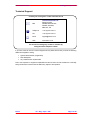
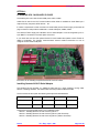
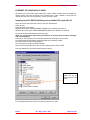
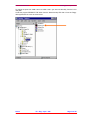
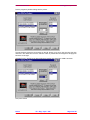
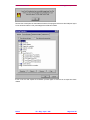
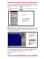
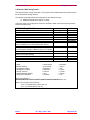
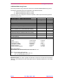
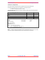
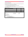
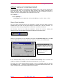
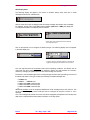
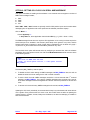
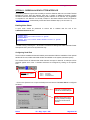
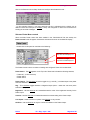
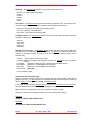
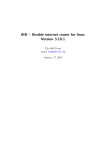
SeaKing System Options Operator Manual The electronic version of this document is the controlled copy. Therefore all printed versions of this document are uncontrolled. Supplied by Issue 3 TIL – Eng – Spec – 040 SeaKing System Options OM COPYRIGHT © Tritech International Ltd The copyright in this document is the property of Tritech International Limited. The document is supplied by Tritech International Limited on the understanding that it may not be copied, used, or disclosed to others except as authorised in writing by Tritech International Limited. Tritech International Limited reserved the right to change, modify and update designs and specifications as part of their ongoing product development programme. F063.1 Tritech International Ltd SeaKing System Options OM Handling of Electrostatic-Sensitive Devices ................................................................................5 Warranty Statement ........................................................................................................................6 Technical Support ..........................................................................................................................7 Option 1:..........................................................................................................................................8 A) SeaKing SCU 3 Auxiliary I/O Card ............................................................................................8 Installing Quatech AUX I/O Serial Adapter ....................................................................................8 Section 1: Installing Quatech DS-100 Card using Win 3.11...........................................................9 Section 2: Installing Quatech DS-100 Card using Win 9x (with driver disk) ...................................9 Section 3: Installing Quatech DS-100 Card using Win 9x (without driver disk) ............................11 B) SeaNet SCU Auxiliary I/O Card ...............................................................................................12 Installing Lava PCI RS232 AUXilliary ports to SeaNet SCU under Win 98. .................................12 Option 2: PipeTracker Surface Interface.....................................................................................17 Option 3: ProfileR Serial Data Output with Ping Times .............................................................19 Option 4: Additional Bathy Serial Message Outputs .................................................................22 Option 5: Bathy 2nd Serial Data Message Output .......................................................................28 Option 6: Profiler Serial Output of Mean Altitude.......................................................................29 Option 7: "NMEA 0183" GPS MESSAGE INPUTS .......................................................................33 Option 8: Setting SCU clock via Serial NMEA Message ............................................................35 Option 9: Connecting Serial device to Sonar AUX Port.............................................................36 Option 10: Auto-Setting Bathy MANUAL values with Auto calc'S ............................................41 Option 11: Sidescan Alden Plotter Interface ..............................................................................42 Issue 3 TIL – Eng – Spec – 040 Page 4 of 44 Tritech International Ltd SeaKing System Options OM Handling of Electrostatic-Sensitive Devices Attention Observe Precautions for handling Electrostatic Devices Caution Handling of Electrostatic-Sensitive Devices Certain semiconductor devices used in the equipment are liable to damage due to static voltages. Observe the following precautions when handling these devices in their unterminated state, or sub-units containing these devices: • Persons removing sub-units from any equipment using electrostatic sensitive devices must be earthed by a wrist strap via a 1MΩ resistor to a suitable discharge reference point within the equipment. • Soldering irons used during any repairs must be low voltage types with earthed tips and isolated from the Mains voltage by a double insulated transformer. Care should be taken soldering any point that may have a charge stored. • Outer clothing worn must be unable to generate static charges. • Printed Circuit Boards (PCBs) fitted with electrostatic sensitive devices must be stored and transported in appropriate anti-static bags/containers. F110.0 Issue 3 TIL – Eng – Spec – 040 Page 5 of 44 Tritech International Ltd SeaKing System Options OM Warranty Statement Tritech International Limited herein after referred to as TIL TIL warrants that at the time of shipment all products shall be free from defects in material and workmanship and suitable for the purpose specified in the product literature. The unit/system warranty commences immediately from the date of customer acceptance and runs for a period of 365 days. Customer acceptance will always be deemed to have occurred within 72 hours of delivery. Note: Any customer acceptance testing (if applicable) must be performed at either TIL premises or at one of their approved distributors unless mutually agreed in writing prior to despatch. Conditions: These include, but are not limited to, the following: 1 The warranty is only deemed to be valid if the equipment was sold through TIL or one of its approved distributors. 2 The equipment must have been installed and commissioned in strict accordance with approved technical standards and specifications and for the purpose that the system was designed. 3 The warranty is not transferable, except or as applies to Purchaser first then to client. 4 TIL must be notified immediately (in writing) of any suspected defect and if advised by TIL, the equipment subject to the defect shall be returned by the customer to TIL, via a suitable mode of transportation and shall be freight paid. 5 The warranty does not apply to defects that have been caused by failure to follow the recommended installation or maintenance procedures. Or defects resulting from normal wear & tear, incorrect operation, fire, water ingress, lightning damage or fluctuations in vehicles supply voltages, or from any other circumstances that may arise after delivery that is outwith the control of TIL. (Note: The warranty does not apply in the event where a defect has been caused by isolation incompatibilities.) 6 The warranty does not cover the transportation of personnel and per diem allowances relating to any repair or replacement. 7 The warranty does not cover any direct, indirect, punitive, special consequential damages or any damages whatsoever arising out of or connected with misuse of this product. 8 Any equipment or parts returned under warranty provisions will be returned to the customer freight prepaid by TIL 9 The warranty shall become invalid if the customer attempts to repair or modify the equipment without appropriate written authority being first received from TIL. 10 TIL retains the sole right to accept or reject any warranty claim. 11 Each product is carefully examined and checked before it is shipped. It should therefore be visually and operationally checked as soon as it is received. If it is damaged in anyway, a claim should be filed with the courier and TIL notified of the damage. Note: TIL reserve the right to change specifications at any time without notice and without any obligation to incorporate new features in instruments previously sold. Note: If the instrument is not covered by warranty, or if it is determined that the fault is caused by misuse, repair will be billed to the customer, and an estimate submitted for customer approval before the commencement of repairs. F167.1 Issue 3 TIL – Eng – Spec – 040 Page 6 of 44 Tritech International Ltd SeaKing System Options OM Technical Support Contact your local agent or Tritech International Ltd Mail Tritech International Ltd. Peregrine Road, Westhill Business Park, Westhill, Aberdeen, AB32 6JL, UK Telephone ++44 (0)1224 744111 Fax ++44 (0)1224 741771 Email [email protected] Web www.tritech.co.uk An out-of-hours emergency number is available by calling the above telephone number If you have cause to use our Technical Support service, please ensure that you have the following details at hand prior to calling: • • • System Serial Number (if applicable) Fault Description Any remedial action implemented Due to the expansion of equipment capabilities and the fact that new sub-modules are continually being introduced, this manual cannot detail every aspect of the operation. Issue 3 TIL – Eng – Spec – 040 Page 7 of 44 Tritech International Ltd SeaKing System Options OM OPTION 1: A) SEAKING SCU 3 AUXILIARY I/O CARD The SeaKing SCU has 2 built-in serial COM ports; COM1, COM2. COM2 Port is used for the RAT communications whilst COM1 is available for Serial Data input / output to Survey computers, GPS devices… etc. It is often a requirement to have more than one serial COM port and Tritech supply a Card that will plug into the SCU and provide an additional 2 x serial COM ports; COM3, COM4. The card that Tritech supply is the 'Quatech Aux I/O' Serial Adapter. It can be recognised by it's 2 x 9-pin Male 'D' connectors on the back-plane of the SCU. If your SCU does not have this optional Serial I/O Card installed then please contact Tritech for details of availability. The Remote Communications manual contains instructions on how to configure the SCU serial COM ports. Instructions for re-/installing the optional Serial I/O Card now follows… Installing Quatech AUX I/O Serial Adapter The Quatech DS-100 provides 2 x additional COM ports for a SCU processor running either Winson or Seaking Software. The Quatech DS-100 card provides COM3 and COM4. The SCU should be set-up with the following interrupts and base addresses: COM PORT 1 2 3 4 INTERRUPT 4 3 5 11 03F8 02F8 03E8 02E8 BASE ADDRESS Please refer to the appropriate section for an installation guide: Section 1: Installing Quatech DS-100 Card using Win 3.11 Section 2: Installing Quatech DS-100 Card using Win 9x (with driver disk) Section 3: Installing Quatech DS-100 Card using Win 9x (without driver disk) Issue 3 TIL – Eng – Spec – 040 Page 8 of 44 Tritech International Ltd SeaKing System Options OM Section 1: Installing Quatech DS-100 Card using Win 3.11 • • • Insert the Quatech DS-100 serial adapter card into a spare ISA slot on the motherboard and start-up the SCU. 386/486 requires no BIOS set-up of serial ports (NB: 95% of Winson SCU-3’s are 386/486). Pentiums will require BIOS set-up in the same way as a Win 9x installation. Installation 1. Double click Main => double click Control Panel => double click Ports. 2. Highlight COM 3 => Click on Settings. 3. Click on Advanced. => Change the Base I/O Port Address to 03E8. => Change the Interrupt Request Line (IRQ) to 5. => Click on OK. 4. Click on OK. 5. Highlight COM 4 => Click on Settings. 6. Click on Advanced. => Change the Base I/O Port Address to 02E8. => Change the Interrupt Request Line (IRQ) to 11. => Click on OK. 7. Click on OK. Section 2: Installing Quatech DS-100 Card using Win 9x (with driver disk) • • • Require ‘ISA Communication – Drivers & Utilities Version 2.0’ disk. Insert the Quatech DS-100 serial adapter card into a spare ISA slot on the motherboard and start-up the SCU. Ensure that Interrupts 5 and 11 are allocated for ISA bus use in BIOS (NB: Non Plug and Play/PCI). Part 1: Installation 1. Start => Settings => Control Panel. 2. Double click on Add New Hardware => Click on Next => Click on Next. 3. When asked if you would like Windows to search for your new hardware, select: => No, select from hardware list => Click on Next. 4. Highlight Multi-function adapters => Click on Next. 5. Click on Have Disk. 6. Insert disk labelled ‘ISA Communication – Drivers & Utilities Version 2.0’ => Click on OK. 7. Highlight Quatech DS-100: 2 RS-232 Ports => Click on Next. 8. A list of Interrupts and base addresses will be shown (self-configured with default interrupt values) => Click on Next. 9. Click on Finish. 10. When prompted, remove any disks from drives and restart the SCU. 11. The Hardware Wizard will detect an unknown device => Click on Next. 12. Select Display list of drivers => Click on Next. 13. Highlight Multi-function adapters in list => Click on Next. 14. Click on Have Disk. 15. Insert disk labelled ‘ISA Communication – Drivers & Utilities Version 2.0’ => Click on OK. 16. Quatech Serial Port [3-12-97] should be highlighted => Click on Next => Click on Next. 17. When prompted for Win 98 CD, select to copy files from D:\WIN98 => Click on OK. 18. Click on Finish. Issue 3 TIL – Eng – Spec – 040 Page 9 of 44 Tritech International Ltd SeaKing System Options OM Part 2: Changing Resources using Device Manager 1. 2. 3. 4. 5. 6. 7. 8. 9. 10. 11. Start => Settings => Control Panel. Double click on System. Select the Device Manager tab. Double click on Multi-function adapters. Highlight Quatech DS-100: 2 RS-232 Ports and click on Properties. Select the Resources tab. Ensure that there are two input/output ranges set at ‘03E8 – 03EF’ and ‘02E8 – 02EF’ respectively. If the first Interrupt Request in the list is not 05, then: • Highlight the first Interrupt Request => Click on Change Setting. • Change the Interrupt value from XX to 5 (where XX is the default IRQ number) => Click on OK. If the second Interrupt Request in the list is not 11, then: • Highlight the second Interrupt Request => Click on Change Setting. • Change the Interrupt value from XX to 11 (where XX is the default IRQ number) => Click on OK. Click on OK. When prompted, remove any disks from drives and restart the SCU. Part 3: Check Quatech Serial Ports COM3 & COM4 are available 1. 2. 3. 4. 5. 6. 7. 8. 9. Start => Settings => Control Panel. Double click on System. Select the Device Manager tab. Double click on Ports (COM & LPT). NB: Quatech serial port (COM 3) & Quatech serial port (COM 4) should be displayed in the list. Highlight Quatech Serial Port (COM 3) => Click on Properties. Select the Resources tab. • Interrupt Request should be set at 05. • Input/Output range should be set at 03E8 – 03EF. => Click on OK. Highlight Quatech Serial Port (COM 4) => Click on Properties. Select the Resources tab. • Interrupt Request should be set at 11. • Input/Output range should be set at 02E8 – 02EF. => Click on OK. Click on OK. NB: If any of the Quatech Serial Port COM3 or COM4 settings are not correct, repeat Part 2: Changing Resources using Device Manager. Issue 3 TIL – Eng – Spec – 040 Page 10 of 44 Tritech International Ltd SeaKing System Options OM Section 3: Installing Quatech DS-100 Card using Win 9x (without driver disk) • • Insert the Quatech DS-100 serial adapter card into a spare ISA slot on the motherboard and start-up the SCU. Ensure that Interrupts 5 and 11 are allocated for ISA bus use in BIOS (NB: Non Plug and Play/PCI). Installation 1. Start => Settings => Control Panel. 2. Double click on Add New Hardware => Click on Next => Click on Next. 3. When asked if you would like Windows to search for your new hardware, select: => No, select from hardware list => Click on Next. 4. Highlight Ports (COM & LPT) => Click on Next. 5. Highlight (Standard port types) under Manufacturers list and highlight Communications Port under Models list => Click on Next. 6. A list with a default Interrupt value and base address will be shown => Click on Next. 7. When prompted to restart the SCU, click on NO. 8. Start => Settings => Control Panel. 9. Double click on System. 10. Select the Device Manager tab. 11. Double click on Ports (COM & LPT). 12. Highlight Communications Port (COM3) => Click on Properties. 13. Click on the Resources tab. 14. Highlight Input/Output Range => Click on Change Setting. NB: If you are told that the resource setting cannot be modified change the Basic Configuration setting in the drop down list above and repeat step 14. 15. Change Value to 03E8 – 03EF => Click on OK. 16. Highlight Interrupt Request => Click on Change Setting. 17. Change Value to 05 => Click on OK. 18. Click on OK. 19. When prompted, shut down and restart the SCU. 20. Repeat steps 1 to 11. 21. Highlight Communications Port (COM4) => Click on Properties. 22. Click on the Resources tab. 23. Highlight Input/Output Range => Click on Change Setting. NB: If you are told that the resource setting cannot be modified change the Basic Configuration setting in the drop down list above and repeat step 23. 24. Change Value to 02E8 – 02EF => Click on OK. 25. Highlight Interrupt Request => Click on Change Setting. 26. Change Value to 11 => Click on OK. 27. Click on OK. 28. When prompted, shut down and restart the SCU. Issue 3 TIL – Eng – Spec – 040 Page 11 of 44 Tritech International Ltd SeaKing System Options OM B) SEANET SCU AUXILIARY I/O CARD The Seanet SCU has 2 built-in serial COM ports; COM1, COM2. Generally both are available for remote comms use since the Pointer on the Seanet RAT is PS2. However if extra ports are required the LAVA PCI card is supplied by Tritech to provide 2 more. Installing Lava PCI RS232 AUXilliary ports to SeaNet SCU under Win 98. Fit the card to the central PCI slot of the 5 on the SCU motherboard Switch on SCU. During the boot up of the SCU Windows 98 will report “NEW HARDWARE FOUND LAVA D SERIAL PCI PORT A” Windows 98 will then report “NEW HARDWARE FOUND LAVA D SERIAL PCI PORT B” The drivers will then automatically load for both ports NOTE If a card has been fitted during manufacture of the SCU then the above messages may not be displayed However you can confirm if the card has been detected by checking the control Panel. From the Windows START button press SETTINGS then CONTROL PANEL. The control panel contents will be displayed From here open the program marked SYSTEM. Click the “Device manager” Tab on the top of the system panel as shown below The LAVA Dserial PCI ports A & B should appear as shown… Lava ports will be initially set up as Com5 and Com 6 as shown. For the SONV3 software to work the com ports must be set to 3 and 4 Issue 3 TIL – Eng – Spec – 040 Page 12 of 44 Tritech International Ltd SeaKing System Options OM To change the ports from COM 5 and 6 to COM 3 and 4 you must use the utility from the LAVA utility disk. Locate the program REDIRECT.EXE either from the Seanet backup ZIP disk or from the Floppy disk supplied with the card. As shown below: Issue 3 TIL – Eng – Spec – 040 Page 13 of 44 Tritech International Ltd SeaKing System Options OM Run the program by double clicking with the pointer. The panel above shows the current setup on the left, allows you to set a new port using the drop down list in the middle and once the “redirect” button is pressed the new assignment to apply will be shown on the right. Highlight Port A in the left box as shown below and set the drop down list to COM 3 as shown. Now press redirect Issue 3 TIL – Eng – Spec – 040 Page 14 of 44 Tritech International Ltd SeaKing System Options OM COM 3 will now be marked in the right box as shown below. Repeat for the Port B to set it to COM 4 Once both have been set ensure your screen matches with the panel below. Especially the right hand box :-”Reassigned ComPort names” Now press the APPLY button for the changes to take effect The following confirmation will appear as the software closes. Issue 3 TIL – Eng – Spec – 040 Page 15 of 44 Tritech International Ltd SeaKing System Options OM Re enter the Control panel as instructed at the start of the program and ensure the COM port layout is now as below with the LAVA ports assigned to COM3 and COM4. If this is not the case repeat the redirection process again to ensure that no steps have been missed. Issue 3 TIL – Eng – Spec – 040 Page 16 of 44 Tritech International Ltd SeaKing System Options OM OPTION 2: PIPETRACKER SURFACE INTERFACE This is a one-way communications between the Pipetracker Surface Console and the SeaKing SCU. The telemetry link between them is a 2-wire (RS-232 Tx, RS-232 Gnd) serial cable to transmit the pipe position data from the Pipetracker Console to the SCU COM Port. SeaKing surface software V1.40 onwards has provision to accept serial data strings from 3 types of Pipetracker system… 1. TSS 340 2. TSS 350 3. Innovatum The data strings from any of these systems can be sent to ANY available serial COM port on the SCU processor unit. Data is one way and the following cable wiring applies… SCU 9-pin 'D' Male (COM 1 / 3 / 4) Pipetracker Console (Serial RS-232 Port) Pin 2 (Rx) Tx Pin 3 (Tx) Not Connected Pin 5 (Gnd) Rx Ground The following steps should be followed to configure the interface thereafter… Step 1: Once the serial cable connecting the SCU to the Pipetracker console has been installed, the Pipetracker serial output will then need to be configured on it's surface console (refer to the Pipetracker documentation for this). Step 2: The next step is to configure the COM port on the SCU Processor unit to match the RS-232 transmission settings of the Pipetracker console. In the SeaKing SONV3 surface software, click on the 'Remote' Tools menu (indicated by spanner icon) and Press the 'Remote Comms Setup' button… Issue 3 TIL – Eng – Spec – 040 Page 17 of 44 Tritech International Ltd SeaKing System Options OM Referring to the 'Remote Comms Setup' menu shown on previous page, set the correct COM port settings to match the Pipetracker Console. Ensure that the COM port is enabled (= 'True') and that the Status Indicator back on main screen is Blue (see screen image below). Step 3: Click on the Profiler Tools menu button (spanner icon) and enable the 'Pipetracker' check-box as shown below… Click on 'More Options'… … Enable 'Pipetracker' check-box and then set the diameter of the pipe for purposes of graphical simulation. Step 4: Ensure that the Serial data output message is being received from the Pipetracker console. The LATeral & VERtical Positions, ALTitude and depth of BURial should be displayed in the Text Boxes on the upper right of the Profiler display. A graphical representation of the pipe will also be displayed inside the Profiler display box… Top of pipe is at Lateral and Vertical position inputs, referenced to origin (0,0) = Magnetometer # Datum Point . Channel Status Indicators Channels 1,2,3 are allocated a COM port in the 'Remote Comms Setup' menu (shown earlier): Blue Status = Port Good. Red Status = Port Bad or Not Configured. # If it is required to maintain screen origin (0,0) as the common Vehicle Datum Point, the Magnetometer Datum Point can be offset from this by applying an X, Y OFFSET in the [PRF] section of the C:\WINDOWS\SONV3SO.INI file (applies to SONV3 V1.45 onwards)… ;PipeTracker Datum Offset X,Y (in mm for metric users) PIPEOFFS=0,0 Issue 3 TIL – Eng – Spec – 040 Page 18 of 44 Tritech International Ltd SeaKing System Options OM OPTION 3: PROFILER SERIAL DATA OUTPUT WITH PING TIMES In the standard Profiler system, the "V4" serial output Profiler messages only give information relating to the Slant Ranges for each of the Pings within the Scan. There are 2 formats of "V4" data, these being 'Raw' and 'Processed'. Typically, a profiler scan will have around 100 to 200 Pings generated in each scan (1 Ping produces 1 Point in the Scanned Profile). For serial transmission, it may be necessary to increase the Baud Rate to 19,200 Baud when transmitting dual Profiler data with Appended Ping Times out of the same COM Port. Important: In order to include the appended 'Ping Time' data in the Profiler output messages, in 'SONV3' the user must select an Application that includes an Attitude Sensor interface… Click on 'Menu' -> Choose 'AppSetup' -> In drop-down list, select Application that includes 'A' (e.g. 'PA' = Profiler + Attitude Sensor). When a 'PA' Application is running, the Serial Output Profiler messages will include the Appended message. This will be one of 2 formats depending on whether a Tritech Attitude / Pitch-Roll Sensor is connected; 1. With Tritech Attitude / Pitch-Roll Sensor connected - Appended message will be Roll Angle data for each Ping. N.B. This message format will be supplied in the Pitch-Roll Sensor manual. 2. Without Tritech Attitude / Pitch-Roll Sensor connected - Appended message will be Ping Time data. 1) An example of a 'Raw' Profiler output message for a very short (5-ping) scan is as follows; %D0068022501+00000+00000+00000+00000+000000000303184+0081500015273302000330 010666706667066670666706667<CR><LF> 2) An example of the above with the Appended 'Ping Time' data (delta mode) is as follows; %D0081022501+00000+00000+00000+00000+000000000303184+0081500015273302000330 160666706667066670666706667*01801600+007+007+006+006<CR><LF> The full format of the "V4" Profiler message output with the Appended Ping Time data now follows… Issue 3 TIL – Eng – Spec – 040 Page 19 of 44 Tritech International Ltd SeaKing System Options OM Profiler System Reply Data Structure Extended with Appended Ping Time Data (Applies to Profiler + Attitude ‘PA’ applications when no valid data from Tritech Roll Sensor) * See Note2 Data Description Head Installation Positions Relative to Vehicle Datum Horizontal X Position in millimetres Vertical Y Position in millimetres Longitudinal Z Position in millimetres Rotational R Position in 1/10 Gradians EchoRanging Time Correction in microseconds Number of Profile Samples (NPS) Scan Start Angle in 1/16 Gradians Step size and Direction during scan in 1/16 Gradians (008=Ult, 016=Hi, 024=Med, 032=Lo) Velocity of Sound in metres / second * 10 ( dm/sec ) Time at Start of Scan Duration of Scan in Units of 1 milliseconds Profiler Head Operating Mode Bit 0 = 0 = Orientation Upright Bit 0 = 1 = Orientation Reversed Bit 4 = 1 = Profiler data sent to SCU includes Ping Times. Valid with Attitude Sensor Apps. E.G. Upright = “000” Reversed = “001” Upright, Profiler data sent to SCU includes ping Times = “016” NPS * Profile Data Points Appended Ping Time Data – Start Character Ping Time Data Mode * See Note1 a) Normal Time Mode b) Delta Time Mode DataRange Data Types -5000 to +5000 -5000 to +5000 -5000 to +5000 -02000 to +02000 -100 to +100 00001 to 00799 00000 to 06392 -032 (Scan Left) to +032 (Scan Right) 14000 to 15500 (in 1 metre steps) 00000000 to 23595999 0 to 65535 0 to 7 INTEGER INTEGER INTEGER INTEGER INTEGER CARDINAL CARDINAL SHORTINT 0 to 65535 NPS*CARDINAL ‘*’ 000 to 018 1*CHAR SHORTCARD a) Normal Mode; 00000 to 65535 CARDINAL CARDINAL TIME CARDINAL BYTE = “016” = “018” Normal Time Mode = st st 1 Time = 1 Ping Tx Time (Time of Day in msec) – Time at Start of Scan (field 10 above), 2nd Time = 2nd Ping Tx Time (Time of Day in msec) – Time at Start of Scan, …etc Delta Time Mode = st st 1 Time = 1 Ping Tx Time (Time of Day in msec) – Time at Start of Scan (field 10 above). All other Ping Times thereafter are delta values (msec) showing Time variance relative to the preceding Ping Time. NPS * Ping Time Data (Transmit Time of Ping) Where; 1st Time corresponds to 1st Profile data point, 2nd Time corresponds to 2nd Profile Data Point…etc. b) Delta Mode; 1st Ping Time = 00000 to 65535 2nd -> Last Ping Time = +126 to –127 CARDINAL SHORTINT * See Note3 Issue 3 TIL – Eng – Spec – 040 Page 20 of 44 Tritech International Ltd SeaKing System Options OM Example: Head at XYZR=0, no time correction, 5 * 5metre ranges in microseconds, Start at 199, Ultimate, PRFRT, Vprop = 1500, Scan Start at 15:27:33:02, Duration 33msecs, Orientation Upright, 1st Ping Time at 15:27:34:62, 2nd at 15:27:34:627, 3rd at 15:27:34:634, 4th at 15:27:34:64, 5th at 15:27:34:646. ASCIIText = a) Normal Time Mode Ping Time: “+00000+00000+00000+00000+000000000303184+008150001527330200033016066670666706667 0666706667*01601600+01607+01614+01620+01626” b) Delta Time Mode Ping Times: “+00000+00000+00000+00000+000000000303184+008150001527330200033018066670666706667 0666706667*01801600+007+007+006+006” [N.B. Consult Tritech before changing RV4VER, default will be RV4VER=2] * Note 1: Controlled by RV4VER in SONV3SO.INI. [RV4VER=0 for Normal Mode, RV4VER=2 for Delta Mode] * Note 2: This Mode can also be forced by setting RV4VER=16 in SONV3SO.INI. It will override Roll Angle Output to give Ping Time Outputs in the extended part of the message. * Note 3: +127 and –128 are delta overflow error conditions Issue 3 TIL – Eng – Spec – 040 Page 21 of 44 Tritech International Ltd SeaKing System Options OM OPTION 4: ADDITIONAL BATHY SERIAL MESSAGE OUTPUTS The SeaKing Bathymeter includes 5 additional Serial Output Message types in SeaKing surface software V1.50 onwards. These messages are the same formats that are supported on a UK94 Bathy system (circa June 2000). The additional 5 messages are not enabled as default and the user will only have 4 message types to choose from normally; 1. 2. 3. 4. Winson Raw. Winson Processed. SeaKing Long. SeaKing Short. In order to enable the additional 5 message types, the user will need to edit the C:\Windows\Sonv3so.ini file and move down through 4/5 of the file to find the following section… ;***************************************************************** [BATHY1] ;; Bathy1 uses Normal, nominal 4Hz data rate settings in SONV3.CFG ; Standard Output Formats=3, Additional Output Formats=8, Diagnostic Format=9 TOPFORMAT=3 ;TOPFORMAT=8 Change the last 2 lines above to the following to change from the 4 message options (0,1,2,3) to the 9 message options (0,1,…7,8)… ;TOPFORMAT=3 TOPFORMAT=8 The additional 5 output message types are as follows; 5. 6. 7. 8. 9. Standard UK90. Alternate UK90. MB1000 / HB200. Alternate 1. Alternate 2. The formats of each of these will now be described… Issue 3 TIL – Eng – Spec – 040 Page 22 of 44 Tritech International Ltd SeaKing System Options OM 1. Standard UK90 String Format This format provides a string format that is identical to the original UK90 string format. The following serial data formats are configurable on the UK94 surface unit: a) 4800 baud, 8 data bits, 2 stop bit, no parity. b) 9600 baud, 8 data bits, 2 stop bit, no parity. [These may need to be configured on the SCU to replicate a UK94 output if the receiving terminal expects this data format] UK90 Std - Reply Data Structure Data Description Depth in metres (includes entered vertical or zero offsets) Space character Altitude in metres (includes entered vertical offset) Space character Altitude in metres (includes entered vertical offset) Space character Temperature in degrees Centigrade 7 x Space characters Atmospheric pressure in mbar (either manually entered value or obtained from the surface Barometric sensor) Space character Velocity of Sound in metres per second * 10 (calculated from Conductivity readings or ‘Manual’ VOS if no CT probe) Space character Mean density of seawater * 10000 (or Manual entered value if no CT probe readings) Space character Height in metres of Barometric Sensor above Sea level Terminator (Carriage Return + Line Feed) Example: Depth Altimeter reading Temperature reading Atmospheric Pressure Velocity of Sound Relative Seawater Density Height above Sea-level = 136.92 metres = 24.75 metres = 5 degrees C = 1004 mbar = 1475 m/s = 1.019 = 15 metres Data Range 0 to 4000.00 N/A 0 to 99.99 N/A 0 to 99.99 N/A 0 to 35 N/A 900 to 1100 Field Range Dxxxx.xx Axx.xx Axx.xx Txx Pxxxx N/A 14000 to 15500 Vxxxxx N/A 9000 to 11000 dxxxxx N/A 0 to 99 N/A Hxx <CR><LF> = D0136.92 = A24.75 = T05 = P1004 = V14750 = d10190 = H15 ASCII Output Always = “D0136.92A24.75A24.75T05P1004V14750d10190H15<CR><LF>” Where; “” is a space (ASCII code 32), “<CR>” is Carriage Return (ASCII code 13), “<LF>” is Line Feed (ASCII code 10). Issue 3 TIL – Eng – Spec – 040 Page 23 of 44 Tritech International Ltd SeaKing System Options OM 2. Alternate UK90 String Format This format provides a string format that is very similar to the standard UK90 string format but with the second altitude reading removed. The following serial data formats are configurable on the UK94 surface unit: a) 4800 baud, 8 data bits, 2 stop bit, no parity. b) 9600 baud, 8 data bits, 2 stop bit, no parity. [These may need to be configured on the SCU to replicate a UK94 output if the receiving terminal expects this data format] UK90 Alt - Reply Data Structure Data Description Depth in metres (includes entered vertical or zero offsets) Space character Altitude in metres (includes entered vertical offset) Space character Temperature in degrees Centigrade 7 x Space characters Atmospheric pressure in mbar (either manually entered value or obtained from the surface Barometric sensor) Space character Velocity of Sound in metres per second * 10 (calculated from Conductivity readings or ‘Manual’ VOS if no CT probe) Space character Mean density of seawater * 10000 (or Manual entered value if no CT probe readings) Space character Height in metres of Barometric Sensor above Sea level Terminator (Carriage Return + Line Feed) Example: Depth Altimeter reading Temperature reading Atmospheric Pressure Velocity of Sound Relative Seawater Density Height above Sea-level = 136.92 metres = 24.75 metres = 5 degrees C = 1004 mbar = 1475 m/s = 1.019 = 15 metres Data Range 0 to 4000.00 N/A 0 to 99.99 N/A 0 to 35 N/A 900 to 1100 Field Range Dxxxx.xx Axx.xx Txx Pxxxx N/A 14000 to 15500 Vxxxxx N/A 9000 to 11000 dxxxxx N/A 0 to 99 N/A Hxx <CR><LF> = D0136.92 = A24.75 = T05 = P1004 = V14750 = d10190 = H15 ASCII Output Always = “D0136.92A24.75T05P1004V14750d10190H15<CR><LF>” Where; “” is a space (ASCII code 32), “<CR>” is Carriage Return (ASCII code 13), “<LF>” is Line Feed (ASCII code 10). Issue 3 TIL – Eng – Spec – 040 Page 24 of 44 Tritech International Ltd SeaKing System Options OM 3. MB1000/HB200 String Format This format provides a string format that is identical to the standard MB1000/HB200 string format. The following serial data formats are configurable on the UK94 surface unit: a) 4800 baud, 8 data bits, 2 stop bit, no parity. b) 9600 baud, 8 data bits, 2 stop bit, no parity. [These may need to be configured on the SCU to replicate a UK94 output if the receiving terminal expects this data format] MB1000/HB200 - Reply Data Structure Data Description Depth in metres (includes entered vertical or zero offsets) Space character Altitude in metres (includes entered vertical offset) Space character Temperature in degrees Centigrade Space character Atmospheric pressure in mbar (either manually entered value or obtained from the surface Barometric sensor) Space character Velocity of Sound in metres per second (calculated from Conductivity readings or ‘Manual’ VOS if no CT probe) Space character Mean density of seawater (or Manual entered value if no CT probe readings) Terminator (Carriage Return + Line Feed) Example: Depth Altimeter reading Temperature reading Atmospheric Pressure Velocity of Sound Relative Seawater Density Data Range 0 to 999.99 N/A 0 to 99.99 N/A 0 to 35 N/A 900 to 1100 Field Range Dxxx.xx Axx.xx Txx Pxxxx.x N/A 1400 to 1550 Vxxxx.x N/A .9 to 1.1 dx.xxxx N/A <CR><LF> = 136.92 metres = 24.75 metres = 5 degrees C = 1004 mbar = 1475 m/s = 1.019 = D136.92 = A24.75 = T05 = P1004.0 = V1475.0 = d1.0190 ASCII Output Always = “D136.92A24.75T05P1004.0V1475.0d1.0190<CR><LF>” Where; “” is a space (ASCII code 32), “<CR>” is Carriage Return (ASCII code 13), “<LF>” is Line Feed (ASCII code 10). IMPORTANT NOTE: If a depth of greater than 999.99m is produced, the depth field is extended to “Dxxxx.xx”. This is different from the UK94 system which at >999.99m outputs Dxxx.xx to indicate over range. Issue 3 TIL – Eng – Spec – 040 Page 25 of 44 Tritech International Ltd SeaKing System Options OM 4. Alternate 1 String Format This output provides a string format that is compatible with the Ulvertech data format. The following serial data formats are configurable on the UK94 surface unit: a) 9600 baud, 8 data bits, 2 stop bit, no parity. [These may need to be configured on the SCU to replicate a UK94 output if the receiving terminal expects this data format] Alternate 1 - Reply Data Structure Data Description Depth in centimetres (includes entered vertical or zero offsets) Comma character Altitude in centimetres (includes entered vertical offset) Terminator (Carriage Return + Line Feed) Example: Depth Altimeter reading = 87.92 metres = 24.75 metres Data Range 0 to 99999 Field Range ddddd N/A 0 to 9999 N/A , aaaa <CR><LF> = 08792 = 2475 ASCII Output Always = “08792,2475<CR><LF>” Where; “,” is a comma (ASCII code 44), “<CR>” is Carriage Return (ASCII code 13), “<LF>” is Line Feed (ASCII code 10). NOTE: If a depth of greater than 999.99m is found, the depth field is shown as xxxxx to indicate over range. Alternate 2 message should be used for systems rated to over 999.99m. Issue 3 TIL – Eng – Spec – 040 Page 26 of 44 Tritech International Ltd SeaKing System Options OM 5. Alternate 2 String Format This output provides a string format that is compatible with the Ulvertech data format but with an extra depth digit to allow readings greater than 999.99metres. The following serial data formats are configurable on the UK94 surface unit: b) 9600 baud, 8 data bits, 2 stop bit, no parity. [These may need to be configured on the SCU to replicate a UK94 output if the receiving terminal expects this data format] Alternate 2 - Reply Data Structure Data Description Depth in centimetres (includes entered vertical or zero offsets) Comma character Altitude in centimetres (includes entered vertical offset) Terminator (Carriage Return + Line Feed) Example: Depth Altimeter reading = 87.92 metres = 24.75 metres Data Range 0 to 400000 Field Range dddddd N/A 0 to 9999 N/A , aaaa <CR><LF> = 008792 = 2475 ASCII Output Always = “008792,2475<CR><LF>” Where; “,” is a comma (ASCII code 44), “<CR>” is Carriage Return (ASCII code 13), “<LF>” is Line Feed (ASCII code 10). Issue 3 TIL – Eng – Spec – 040 Page 27 of 44 Tritech International Ltd SeaKing System Options OM OPTION 5: BATHY 2ND SERIAL DATA MESSAGE OUTPUT If the SCU is operated with SeaKing surface software V1.50 or later, it will be possible to transmit 2 different (or same?) Bathy output messages out 2 different serial COM ports. As per usual, the 1st Bathy output message type can be selected in the 'SONV3' software 'Bathy Setup' menu (Bathy spanner icon) and a serial COM port allocated in the 'Remote' panel Setup menu (spanner icon). The 2nd Bathy output message is configured in the C:\Windows\Sonv3so.ini file. Edit this file using an Editor such as Windows® NotePad, and move 4/5 down the file to the following section… ;***************************************************************** [BATHY1] ;; Bathy1 uses Normal, nominal 4Hz data rate settings in SONV3.CFG . . . ;; SecondMsgOutput . . ;SecondMsgOutput=-1,2,4 To enable the Second Message Output for the Bathy, change the last line shown above to the following (i.e. remove the ";" character)… SecondMsgOutput=-1,2,4 The 3 numbers in this line configure the output as follows; e.g. SecondMsgOutput=-1,2,9 = Enabled, Chan (2), Diagnostic Format SecondMsgOutput=0,2,4 = Disabled, Chan (2), UK90 Format The following message type codes are supported; 1. Winson Raw = 0 2. SeaKing Long = 1 3. SeaKing Short = 2 4. Winson Processed = 3 5. UK90 = 4 6. UK90 Alternate = 5 7. MB1000 / HB2000 = 6 8. Alternate 1 = 7 9. Alternate 2 = 8 10. Diagnostic = 9 11. SeaKing Mean V.O.S. = 10 Note: Once the Channel is selected, i.e. Chan (2) in above, this Channel will need to be enabled and allocated a serial COM port in 'SONV3'. This is configured in the 'Remote' panel Setup menu (spanner icon). Issue 3 TIL – Eng – Spec – 040 Page 28 of 44 Tritech International Ltd SeaKing System Options OM OPTION 6: PROFILER SERIAL OUTPUT OF MEAN ALTITUDE This feature is available in SeaKing surface software V1.51 onwards. It will operate with a Single or Dual Head Profiler system. At the end of each scan, a Mean Seabed Altitude will be calculated from the profile and transmitted out of the SCU serial port in the format of a TSS Altitude string. The 'Mean Seabed' option will become active by enabling command lines within the software initialisation file on the Surface Control Unit. Edit the C:\Windows\Sonv3so.ini file and move down to the following section… ;***************************** PRF1 ******************************* ' Standard DHP Window, No Roll Sensor Correction [PRF1] . . . ;MeanPrfOutput=-1,1,2,0 ;Gating=200 ; in mm To enable the 'Mean Seabed' output option, change the last 2 lines shown above to the following (i.e. remove the ";" characters)… MeanPrfOutput=-1,1,2,0 Gating=200 ; in mm The 4 numbers in the 1st line configure the output as follows; MeanPrfOutput=a,b,c,d Where; a = Mean Seabed Output Option Enabled/Disabled. {Enabled = -1, Disabled = 0} b = Serial Channel Selection. {Channel1 = 1, Channel2 = 2, Channel3 = 3} c = Profiler Head Selection {Master Only = 0, Slave Only = 1, Both = 2} d = Output String Format {TSS Altimeter, Rxx.xx<cr><lf> = 0} e.g. MeanPrfOutput=-1,2,0,0 = Enabled, Chan (2), Master Profiler, TSS Altimeter Format MeanPrfOutput=0,1,1,0 = Disabled, Chan (1), Slave Profiler, TSS Altimeter Format MeanPrfOutput=0,1,2,0 = Disabled, Chan (1), Both Profilers, TSS Altimeter Format The following message type codes are supported; 1. TSS Altimeter = 0 Issue 3 TIL – Eng – Spec – 040 Page 29 of 44 Tritech International Ltd SeaKing System Options OM The 2nd line is used to set the Gating value that will apply filtering to remove spurious points within the scan; Gating = x Where; x = Gate Value in millimetres, used to distinguish whether the current profile point is within +/- 'x' millimetres of the preceding point. This will eliminate spurious points and spikes present in the profile to achieve a more accurate Mean Seabed calculation. {Default = 200mm} Operating Instructions The Mean Seabed Output will function with a single or dual-head Profiler system. All valid data points within the Scan Packet will be included in the Mean Calculation. Non-valid data points will not be included and these include zero values and points outside a boundary determined by the value of the Gating value entered in the SONV3SO.INI file. The following features have been included… ▪ Any null (zero) data points within the Scan Packet will not be included in the calculation. ▪ If the current data point exceeds the preceding data point by +/- Gating, this current data point will not be included in the Mean calculation. This will eliminate any spurious points and spikes from the Mean Calculation. ▪ In a dual-head operation, if at any time one of the profilers is disabled or is not producing data then a Mean calculation will still be produced using the data from the functional head. ▪ If there is no valid data points then a zero output will be produced. Once the 'Mean Seabed' option has been enabled and configured as described earlier, the operator has "front-end" control of switching on and off Master and Slave head inclusion in the Mean Seabed Output. This "front end" control is available within the 'Remote' Panel setup and is as follows; Step 1: Click on "Spanner" icon in 'Remote' panel to enter the Setup page… Step 2: In the Setup page, the drop-down list at the top left will select between the Master and Slave Profiler Setup pages… ▪ Master = Profiler Slot 2 ▪ Slave = Profiler Slot 3 Serial Channel Selection for full 'V4' Profiler Data output. If used, ensure this does not match the 'Mean Seabed' output channel 'Continuous Data Output' switches Mean Seabed Output Off/On for both Master and Slave Profilers. Issue 3 TIL – Eng – Spec – 040 Page 30 of 44 Tritech International Ltd SeaKing System Options OM Enable ('x') the 'Continuous Data Output' check-box for both Master and Slave to include these head's scan data in the Mean Seabed Output. If both heads are disabled then this will effectively disable the transmission of the Mean Seabed Output string. Step 3: Click on the 'Remote Comms Setup' button in the Setup page to assign a COM port for the Serial Channel selected for 'Mean Seabed' output… … In the above example, the default settings are shown. In this case Serial Channel 1 has been selected and assigned COM 1 Port. The Port must now be Enabled (=True) as indicated for data transmissions to occur. It is also in this area that the Port transmission settings (Baud, Bits, etc) should be configured to match the receiving Terminal. The Scan Packet size and position can be adjusted using the Direction ("Dirn") and Width controls on the RAT controller, i.e. transducer (mounted at centre) Direction = 330 o Width = 45 30 o o o 45 oil fill screw N.B. The 'Mirror Slave' Profiler control is enabled in order to achieve the above direction and scan packet orientation. This control will counter the scan direction of the Slave w.r.t. Master Profiler. In the derivation of the 'Mean Seabed' figure, each data point is first measured by the profiler and returned as a return path Time. The system Velocity Of Sound (Menu -> VOS) is then applied to this to convert this time into a Slant Range, this being the distance to the seabed at the current angle of incidence. With this polar data a 'height off seabed' range is then calculated and if valid is applied in the final Mean Seabed calculation. To be valid, the range must be non-zero and within the Gating restrictions. Issue 3 TIL – Eng – Spec – 040 Page 31 of 44 Tritech International Ltd SeaKing System Options OM 'Mean Seabed' Output String Format In Version 1.51 -> 1.53 software, there is only one string format supported and this replicates the TSS Altimeter output. Upon request, further data formats may be inserted and these will be selectable within the SONV3SO.INI file (see earlier). 1. TSS Altimeter String Format Rxx.xx<cr><lf> Where; R = String Header Character xx.xx = Mean Seabed Range in metres <cr><lf> = String Terminator N.B. "R00.00<cr><lf>" is output when there are no valid Profiler data points in Mean calculation. Issue 3 TIL – Eng – Spec – 040 Page 32 of 44 Tritech International Ltd SeaKing System Options OM OPTION 7: "NMEA 0183" GPS MESSAGE INPUTS These have been available in the SeaKing surface software since V1.26 and until recently were pre-configured at Tritech. In V1.53 they have been included in the Appsetup drop-down list for Sonar and Sidescan Sonar usage whilst other Applications can still be configured by Tritech on request. Look out for the Applications that include 'GPS' in their title… Click on 'Menu' -> Choose 'AppSetup' -> In drop-down list, select Application that includes 'GPS' (e.g. 'S_GPS' = Sonar + GPS). 'Remote' Panel Setup Menu This is the area where the serial port is configured for all data input and output through the available serial ports. Note that the system assigns the COM2 port for the RAT controller - if a serial mouse is used as the pointing device, this should be connected to COM2 also. SCU Processor units have the COM1 port available as standard with option for installing and Auxiliary I/O card to provide additional COM3 and COM4 ports (see earlier option). Remote Panel Clicking on the spanner icon in the 'Remote' Panel opens the RemoteV4 Setup menu. The GPS input is on Slot 14 and this should be allocated a channel (i.e. 'Chan 1') for serial data input; Click on here to allocate and configure a COM port to selected Channel (i.e. Chan 1 in this case) Remote Data Input enables / disables the serial input on selected Channel RemoteV4 Setup In the 'RemoteV4 Setup' menu, click on the Remote Comms Setup button to allocate and configure a COM port for the GPS serial data input (through Chan 1 in this case). The COM1 port is 'factory' assigned against Channel 1 (Chan 1). GPS NMEA 0183 input will often be at 4800 Baud, 8, N, 1 - ensure the correct settings are configured to match the GPS device. This can be changed in the 'Remote Comms Setup' menu if required. Issue 3 TIL – Eng – Spec – 040 Page 33 of 44 Tritech International Ltd SeaKing System Options OM GPS Display Panel The following display will appear in this Panel on 'SONV3' startup when there are no serial messages received from a GPS device; With an active GPS input, the display Panel will change to display the specifics of the message. For example, receipt of any of the NMEA 0183 messages (GGA, GLL or RMC) will display the Co-ordinate information in the display area, as follows: Versions up to V1.50 Versions later than V1.50 * * These values are converted from the GPS Latitude and Longitude outputs. Click on the spanner icon to configure the GPS input type. The following display menu will appear in the GPS display box. Versions up to V1.50 Versions later than V1.50 * * A 'lat/lon' check-box has been added in V1.53 which will toggle the displayed position between Lat/Lon and E/N. The ‘Cal’ flag should be left unchecked under normal operating conditions. This feature can be used when the GPS receiver is sited in a stationary position and will calculate the receiver’s position by averaging all updates since the time when the flag was checked. The button to the immediate right of the ‘Cal’ flag changes the GPS input type setting. Each click of this button will select a new type of GPS input message. Available messages are; OSGB input UTM -1 ..... UTM -60 input NMEA 0183 GGA command input NMEA 0183 GLL command input NMEA 0183 RMC command input Additionally, SONV3 V1.54 will accept the NMEA 0183 "VTG" message from a GPS receiver. This will be received through the same COM port that is configured to accept the "GGA" or "GLL" message. The "VTG' message will provide the Course over Ground (degrees) and Speed over Ground (km/h) data which is displayed below the position information on the Gps panel. Issue 3 TIL – Eng – Spec – 040 Page 34 of 44 Tritech International Ltd SeaKing System Options OM OPTION 8: SETTING SCU CLOCK VIA SERIAL NMEA MESSAGE This option is available in SeaKing surface software V1.53 onwards and now supports a number of NMEA 0183 message formats; 1. 2. 3. 4. 'ZDA' 'RMC' 'GGA' 'GLL' Note: 'RMC', 'GGA', 'GGL' formats are primarily used for GPS position inputs and to enable these message types, an Application with a GPS panel must be selected (see earlier Option)… Click on 'Menu' -> Choose 'AppSetup' -> In drop-down list, select Application that includes 'GPS' (e.g. 'S_GPS' = Sonar + GPS). The 'ZDA' message format does not require a GPS Application to be running but does require the serial COM port to be enabled in the 'Remote' panel Setup menu (spanner icon). Note, that the 'Remote' panel does not appear in certain "single device" Applications such as Sonar only (App = 'S') where an 'S_GPS' would need to be alternatively selected in any case. The 'Set SCU Clock' option will become active by configuring a command line within the software initialisation file on the Surface Control Unit. Edit the C:\Windows\Sonv3so.ini file and move down to the following section… [NEMA] ;;Set clock via NMEA "ZDA" GPS Time ;;0=Off, 1=1 minute update interval, 2 = Max update Interval MIN_TIMER=0 The last line (MIN_TIMER=x) sets the option; 1. To disable and SCU Clock setting via NMEA messages, set MIN_TIMER=0. Note, this will not disable the other SCU Clock setting via the ':SB' V4 serial command. 2. To set the SCU clock with NMEA messages received at 1 minute intervals after 1st received message, set MIN_TIMER=1. For instance, if NMEA messages were received every second, 59 of these messages would be disregarded and the 60th would be processed to set the SCU clock. 3. To set the SCU clock with every NMEA message that is received, set MIN_TIMER=2. Updating the SCU clock periodically is recommended to keep in synchronisation with other devices on the system. Every time that the SCU clock is set, this will also have the affect of updating the onboard clocks in Profilers, Sonars, Bathys and Sidescans, as data time-stamping is handled in each of these devices. Issue 3 TIL – Eng – Spec – 040 Page 35 of 44 Tritech International Ltd SeaKing System Options OM OPTION 9: CONNECTING SERIAL DEVICE TO SONAR AUX PORT It is possible to configure the ‘Aux’ port on a SeaKing Sonar for input of RS232 / RS485 serial message packets. These serial messages may be from devices such as a Gyro Compass or GPS or Altimeter. ASCII messages received through the Sonar ‘Aux’ port do not require a header or Identifier but must be terminated with a Line Feed (<LF>). These messages are restricted to a maximum length of 100 bytes (including <LF>). Note: It is preferred that the altimeter has the RS485 board fitted since this avoids breaking the power isolation in the SeaKing head and also allows the altimeter analogue output to be jumpered through the sonar head on pin 5 (COMDV3 or COMFV3 pcb, JP3 link). Software version 1.40 or later is recommended for operation of the auxiliary port serial interface. Messages through the Sonar ‘AUX’ port are contained in sonar data packets for transmission to the surface control unit. The message is then stripped from the Sonar data and either displayed on screen or serially transmitted out of the SCU COM port. A Message Header is added to the message before it is transmitted out the COM port and the message is also terminated with <CR><LF>: RV4 “Slot Text Message” Control to SonV3 Command “:SA” - Send Text Message to Sonar (Slot 01) Command Data Destination Slot Number e.g. “01” for Sonar 00 Message Length 0000 Text String “......” & <CR><LF> e.g. Send NMEA Gps “$GPGLL,0123.45,N,13155.23,W,211852,A*E0” Msg to Slot 01 “:SA01006A$GPGLL,0123.45,N,13155.23,W,211852,A*E0<CR><LF>” 2 * DIGIT HEXINTEGER BYTES For Example to Send Message “$1D<LF>" to Remote Device on Sonar Slot 1 AUX Port Msg = “$1D” OutPkt = “:SA01000D” & Msg & Chr$(10) (In this Instance Message Length = 13decimal = 000Dhex. At present this length is not checked and may be sent as "0000", e.g. “:SA010000$1D<LF>“ is legal) Reply: “Slot Text Message” - “%A” followed by: Slot Message Header Total Message Length in Hex 0026 (32 decimal) HEXINTEGER Slot Number in Hex Typically 01 HEX Head Type Identifier e.g. Sonar = 22Hex Typically 22 HEX Data Mode 0,1,2,3 Typ. 0 = ASCII DIGIT Raw Data Bit Typ. 0 DIGIT Message Data STRING<CR><LF> STRING e.g Slot 1, Sonar Head(Type 22hex), Tcm2 Compass Message $C70.1P-4.2R-3.5T21.5*15 “%A0026012200$C70.1P-4.2R-3.5T21.5*15<CR><LF>“ For Example: Reply from SonV3 Serial COM Port = InPkt = “%A0026012200$C70.1P-4.2R-3.5T21.5*15<CR><LF>“ Issue 3 TIL – Eng – Spec – 040 Page 36 of 44 Tritech International Ltd SeaKing System Options OM Configuring Seaking Comms Board for AUX Serial I/O Step 1: Before opening the Sonar head to access the Comms board jumpers, using the 'V3Setup' Utility Program configure the following check box settings. These are needed to enable the 'Aux' port; Check the 'Has Aux or Compass' box to enable the Aux Port. Check the 'AuxComm 1 Sec Rate' box to restrict only 1 message per second processing. Note: “Board Rev” box may show SK5 on later Sonar heads, this should not be changed!! If the ‘AuxComm 1 Sec Rate’ check box is disabled, the Sonar will try to send up all data collected through it’s auxiliary port. Please be aware that if the quantity and rate of this data is too great then the interface may hang up. Step 2: The Comms board inside the SeaKing head must be a COMDV3, COMFV3 COMGV3 or COMV5 board and the jumpers should be set as follows. Always ensure that the sonar Aux port is fitted with a Water Block connector. NOTE When connecting an RS232 Tritech Altimeter 1) The Altimeter analogue output must be disabled by removing R1 from the power pcb. 2) Pin 4 and pin 5 on the AUX connector must be linked on the SeaKing comm. Pcb 5V 12V 5V 12V JP3 JP1 JP1 (Pin5 Altimeter Analogue Link through) NET JP5 AUX JP6 JP3 (RS232 Gnd Link) NET R26 JP5 AUX JP6 R26 (removed) JP2 RS232 OFF DV3 / FV3 Comm boards a) RS485 Altimeter Issue 3 (removed) (Enable RS485 Altimeter 'AUX' port) JP2 RS232 ON (Enable RS232 Altimeter 'AUX' port) DV3 / FV3 Comm boards a) RS232 Altimeter TIL – Eng – Spec – 040 Page 37 of 44 Tritech International Ltd NET SeaKing System Options OM NET AUX JP1 AUX JP1 JP2 JP2 (Enable RS232 Altimeter on Aux port) (Enable RS485 altimeter on Aux port) GV3 / V5 Comm Boards c) RS485 Altimeter GV3/V5 Comm Board d) RS232 Altimeter V5 Mod A Comm Board e) RS485 Altimeter V5 Mod A Comm Board f) RS232 Altimeter Issue 3 TIL – Eng – Spec – 040 Page 38 of 44 SeaKing System Options Manual Page 39 of 43 Software Settings Once the Sonar head has been correctly set the following settings are required in the run-time Sonar (‘SONV3’) and Setup (‘V3SETUP’) programs. Do not run these programs at the same time. Step 3: Running ‘SONV3’, first select application "S_RV4" (using 'Menu' – 'AppSetup') and close down and restart the ‘SONV3’ program. Note, "S_RV4" may not be included in earlier software versions contact Tritech for further advise and/or to receive a program update. Access the 'Sonar Tools' menu via the spanner icon in the top-left of the Sonar window. Click on the ‘More Options’ check box and ensure that the 'RV4Aux' box appears and is checked, as follows; N.B. If the ‘RV4Aux’ check box does not appear in the menu, the C:\WINDOWS\SONV3SO.INI will need to be edited. The following lines can be found in the [SON1] section of this file… ;' Allow RV4 input and output messages to Sonar Aux Port RV4AUX=1 …if a semi-colon appears before the RV4AUX=1 command, then this must be removed in order to enable visibility of the ‘RV4Aux’ check box in the 'Sonar Tools' menu; Sonar Tools RemoteV4 Setup Click on the spanner icon the 'Remote' panel Tools menu to open this Setup menu… Step 4: Ensure that 'Sonar Slot 1' is set with 'Continuous Data Output' and 'Copy Input to DDE' boxes checked. This is to enable screen display of the Sonar 'Aux' data. If data is also required to be output from a serial port at the rear of the SCU, then select the appropriate channel (‘None’ shown set below for disablement) and allocate a serial port to this channel in the ‘Remote Comms Setup’. Tritech International Ltd. sksysopt.102 Tritech International Ltd SeaKing System Options OM For display of Sonar 'Aux' data on screen, the 'SysMsg Slot 16' must be set to channel 'DDE1' with 'Remote Data Input' checked, as shown below. The Sonar 'Aux' data will be displayed on-screen in the System Message Bar at the bottom of the 'SONV3' screen display… ‘SONV3’ display screen System Message Bar Issue 3 TIL – Eng – Spec – 040 Page 40 of 44 Tritech International Ltd SeaKing System Options OM OPTION 10: AUTO-SETTING BATHY MANUAL VALUES WITH AUTO CALC'S This option is available in SeaKing surface software V1.53 onwards. The purpose of this feature is to automatically set the manually entered 'Manual' (sometimes called 'System') values for Density & Velocity of Sound with the Auto-updated values calculated from CT Probe readings. The main benefit of this feature is to prevent (or counter) glitches that may occur when CT readings momentarily drop out for any reason. If CR readings dropout momentarily, the surface Bathy software will immediately switch from the "Auto" Density and V.O.S. (calculated from CT) to the "Manual" Density and V.O.S. (entered in Bathy Setup Form). If the Manual values are not close to the Auto-updated values then in the case of the Density, this will cause "jump" in the Depth calculation. If any "jumps" in Depth are encountered then it may be a case that the CT probe readings may have been momentarily invalid for any reason; perhaps a blocked or faulty CT probe. In these circumstances, enabling this feature will help counteract this. In order to enable the "Auto-setting Manual values" feature, the user will need to edit the C:\Windows\Sonv3so.ini file and move down through 4/5 of the file to find the following section… ;***************************************************************** [BATHY1] ;; Bathy1 uses Normal, nominal 4Hz data rate settings in SONV3.CFG . . ;;Auto-update System Density/VOS with CT Auto values ;CTAUTOSYSTEM=-1 … Then change the last line above to the following (i.e. remove the ";" character)… CTAUTOSYSTEM=-1 Save and exit the Sonv3so.ini file and re-run SONV3 where the new changes will immediately take affect. Note: This should only be performed when the Bathy is out of the water as closing down the 'SONV3' program during a dive will result in a reset of the Mean updated Density values. Issue 3 TIL – Eng – Spec – 040 Page 41 of 44 Tritech International Ltd SeaKing System Options OM OPTION 11: SIDESCAN ALDEN PLOTTER INTERFACE The SeaKing Sidescan system has the ability to send the Sidescan data out to an Alden Thermal Parallel-Port Printer. With this interface, there are a number of additional functions including Annotation that have been added into SeaKing surface software V1.52 and later. Any suggestions or requests for new features not currently included in the latest software should be issued to [email protected], or alternatively contact the Tritech Software dept. (+44 1224 744111). Enabling Alden Plotter A quick check should be performed to ensure this is enabled near the end of the C:\Windows\Sonv3so.ini file… [ALDENPRINTER] ; Enable This Line if No Printer in System ;HAVEPRINTER=0 ; Enable this Line if Have Alden Thermal Printer in System HAVEPRINTER=1 …Enable a line by removing the ';' at the start. The above line settings will enable the Alden Plotter and open the LPT1 port for use by this device only. Configuring Serial Port The SCU will be installed with the serial COM1 port as standard. With the installation of the optional Serial AUX I/O card, COM3 and COM4 will also be available on the system (see earlier option). The 'Remote' Panel will indicate what serial channels are open for data I/O. A COM port will be assigned against each of the 3 channels and these are configured by clicking on the spanner icon… Spanner Icon opens Setup menu. Serial Channel Status Indicators; Blue = Grey = Red = Port Open Port Closed Port Bad/Conflict …Click on the Spanner Icon to open the Setup menu and ensure that Sonar Slot 5 is configured as follows… Click here to configure serial channel and enable COM port. Enable 'Remote Data Input' to receive (annotate) messages through the allocated serial channel. Issue 3 TIL – Eng – Spec – 040 Page 42 of 44 Tritech International Ltd SeaKing System Options OM Click on the 'Remote Comms Setup' button and configure the allocated channel… …In this example Channel 1 has been assigned and this is allocated with the COM1 port as default. Ensure this COM port is Enabled (=True) and configured to match the Terminal that is sending the annotate messages. Sidescan Plotter Menu controls When the Alden Plotter control has been enabled in the "SONV3SO.INI" file (see earlier), the Plotter Control Panel will appear minimised in the bottom left corner of the Sidescan display… …Double-click on this panel to maximise to the following… Annotation on Left: drop-down list and display box Annotation on Right: drop-down list and display box The Plotter Control is where a number of settings are configured. These are now described; Plotter Status - This text appears on the Top Left of Panel and indicates the following statuses; ▪ Plotter Off (or Disconnected) ▪ Plotter Offline ▪ Plotter Online Plotter Output - This check-box is used to toggle On ('x') and Off (' ') the data output to the plotter when the Sidescan is active. Neg. - This check-box toggles between a Negative Output (black -> white and vice-versa) when switched On ('x'). Brightness - Use the slider bar to increase/decrease the value of the brightness intensity for the Plotter output. Contrast - Use the slider bar to increase/decrease the contrast setting of the Plotter output. Line Repeat - Same Control as on plotter. Use slider bar to vary number. Gridlines - Use the slider bar to vary the number of Gridlines on the Plotter Output. Issue 3 TIL – Eng – Spec – 040 Page 43 of 44 Tritech International Ltd SeaKing System Options OM PaperType - This drop-down list selects the type of paper used in the Printer; ▪ Panel 0 (i.e. Adopt Printer Panel setting) ▪ Plastic 1 ▪ Plastic 2 ▪ Plastic 3 ▪ Fibre 4 ▪ Film 5 Chan Select - This drop-down list selects which Sidescan Channels to plot. The Sidescan has 2 channels and these are used for the Port Transducer and the Starboard Transducer; ▪ Dual Chan (Plot both Port and Starboard Transducer data) ▪ Left Chan (Plot Port Transducer data) ▪ Right Chan (Plot Starboard Transducer data) Time Mark Interval - The drop-down list sets the interval of the Time Marks (Horizontal Time Line) annotated on the printout. ▪ Mark Off ▪ Mark 30sec ▪ Mark 1min ▪ Mark 2min ▪ Mark 5min Annotation on Left / Right - The drop-down list has several selections for the type of data that is annotated on the Left and Right of the Thermal Paper. The text box will display the data that is selected for annotating and can be used to verify that the data is coming through from the annotator okay. ▪ Text Off (No annotation on this side of paper) ▪ Text Man** (Manual annotation - with keyboard, type text into text box and press 'Annotation' button) ▪ PC Datime (Annotate PC Date and Time - linked with the Time Mark Interval) ▪ Nav Datime (Expansion to include NMEA 0183 messages) ▪ Nav String (Expansion to include NMEA 0183 messages) ▪ Remote Text (See below) ** Only available on Right 'Remote Text' Annotation Messages Section 2 enabled the Sidescan Sonar (Slot 5) Remote Data Input and allocated a serial channel (COM Port) for this. Any ASCII Remote Text messages that are received through this COM Port with the <CR><LF> terminator will be passed to the Plotter Control. In the Plotter Control, Selecting 'Remote Text' from either of the Annotation on Left / Right dropdown lists will transmit the ASCII Remote Text messages to the printer as annotation messages. N.B. The Remote Text messages can be up to 120 ASCII characters in length. Examples of 'Remote Text' message containing UTC Time, Eastings and Northings: Example 1: 093455.12, 230631E, 4283716W<CR><LF> Example 2: GPS 093455.12 230631E 4283716W<CR><LF> Issue 3 TIL – Eng – Spec – 040 Page 44 of 44