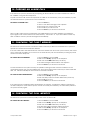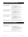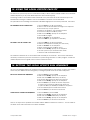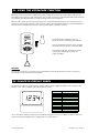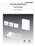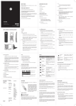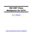
1
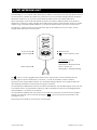
ADVENT xt
WARDEN CALL SYSTEM
V2.0 OPERATORS MANUAL
KIRK 4020/4040 DECT TELEPHONES
WITH A PANASONIC 308 PBX
Tynetec operate a policy of continual product improvement. If any variation
to the details contained in this manual are suspected please contact
Tynetec's Customer Support Department on 01670 352371
15 September 2009
FM0420 issue D Page 1
INDEX
SECTION
1
2
3
4
5
6
7
8
9
10
11
12
13
14
15
16
17
18
19
20
21
22
23
24
25
26
27
28
29
30
31
32
33
34
35
36
37
38
15 September 2009
TOPIC
The Intercom Unit
DECT & Fixed CLI Telephones
Answering a Call
Calling a Resident
Sequential Daily Calls
Call Waiting
Using The PA Function
Using the Fire Alarm Function
Selecting The Operating Mode
Parking an Alarm Call
Checking The Fault Memory
Checking The Call Memory
Setting The System Time & Date
Setting The Daily Alarm Time
Using The Local Offsite Mode
Setting The Local Offsite Dial Sequence
Checking the Controller Firmware Versions
Releasing The Main Entrance Door Lock
Releasing The Keysafe
Releasing a Flat Door Lock
Using The Extracare Function
Caller ID Display Panel
Using The Activity Monitoring Function
To Enable/Disable Activity Monitoring
Activity Monitor Panel
Using The Intruder Function
Adding & Removing Radio Triggers
Checking Intercoms For Privacy
Using The Message Service
Setting Door Entry Call Transfers
Setting 24 Hour Door Entry Calls
Checking Telephones For Privacy/Fault
Data Back-up/Restore Function
Intercom Unit Test Mode
Special Codes Summary
DTMF Key Summary
Internal/External Call Summary
System Configuration Details
PAGE
3
4
5
6
6
7
7
7
8
9
9
9
10
10
11
11
12
12
12
12
13
13
14
15
16
16
17
18
18
19
20
21
22
23
24
25
25
26
FM0420 issue D Page 2
1. THE INTERCOM UNIT
Each dwelling on your scheme will be fitted with an Advent xt intercom unit, there may also be others in
communal areas, corridors and toilets. Any intercom unit or its associated orange pullcords located in
bedrooms, bathrooms, etc, can be used to initiate an alarm call on the warden call system.
When operating in onsite mode all calls are reported on the DECT cordless handset or the fixed CLI
telephones. If there is no onsite manager then calls can be reported via local offsite mode to a mobile
warden using a standard mobile telephone, or via remote offsite mode to a 24 hour control centre.
The Advent xt intercom unit has four pushbuttons and an LED indicator on the front face, and an
orange alarm pullcord on the lower face.
tynetec
No Function
*
#
= Play Message
# No Function
= Privacy Mode On/Off
LED indicator (central)
Alarm Pullcord
Red = Alarm Call
Flashing Red = Extracare Mode
Green = Privacy On
Flashing Blue = Message Waiting
The
button is used to toggle Privacy Mode on/off, when privacy is ON the LED indicator will
illuminate green and the microphone is turned off - you will not be able to hear the resident.
Operation of the orange Alarm Pullcord, any associated ceiling pullcords or the radio pendant will
automatically override the Privacy Mode for approx 15 minutes.
The LED indicator will illuminate red when an alarm call is initiated, the LED will extinguish when the call
is answered. Note, if the LED flashes red after the call is cancelled the intercom is awaiting Extracare
call cancellation - see Section 21 for details.
The LED indicator will flash blue and a series of tones will sound every 60 seconds when a message is
waiting. The message can be heard by pressing the
button. See Section 29 for details on the
Message function.
See Section 34 for details on the intercom unit Test Mode.
15 September 2009
FM0420 issue D Page 3
2. DECT & FIXED CLI TELEPHONES
All DECT cordless handsets and/or fixed CLI telephones will ring when a call exists in Onsite Mode.
To answer a call using a DECT telephone press the Line key, if using a fixed CLI telephone simply lift the
handset.
When answered a speech message will identify the call type and flat number, the residents name may
also be displayed if it has been programmed into the telephone name/number memory.
When the alarm message is understood press the
key to open two-way speech with the caller.
During speech the resident’s VOLUME can be increased with the 1 key or decreased with 2 key.
To end the call using a DECT telephone press the # key followed by the Line key, if using a fixed CLI
telephone press the # key and replace the handset.
DECT Cordless Handset
Fixed CLI Telephone
ALARM
4040
REPLAY
SAVE
ERASE
PLAY
MENU
REDIAL
INT
MAIL
BOOK
MUTE
R
ABC
DEF
1
2
3
GHI
JKL
MNO
4
PQRS
7
5
TUV
6
1
ABC
2
DEF
3
GHI
4
JKL
5
MNO
6
PQRS
7
TUV
8
WXYZ
9
WXYZ
8
LOCK
Line Key
9
SILENT
0
*
0
#
All instructions given in this manual assume a DECT cordless handset is being used with a Panasonic 308
exchange (PBX). If using a fixed CLI telephone simply lift/replace the handset instead of pressing the
Line Key.
For detailed information regarding DECT charging and other handset features see the manufacturers
booklets provided with each telephone.
CALLING A RESIDENT
Press the Line key, enter 8 1 and wait for the “Ready” prompt, then enter the flat number followed by
the key.
MAKING INTERNAL CALLS BETWEEN DECT HANDSETS
Press the Line key followed by the Extension Number (201-208).
Note; It is not possible to make internal calls to/from fixed CLI telephones.
MAKING EXTERNAL CALLS WITH DECT/FIXED CLI HANDSETS
Press the Line key, enter 8 2 and wait for the dial tone.
15 September 2009
FM0420 issue D Page 4
3. ANSWERING A CALL
To answer an alarm call, press the Line key on the DECT cordless handset and listen to the alarm
message in the earpiece (the alarm message will repeat until the key is pressed). Press the key
after the message and speak with the caller. To cancel the alarm call press the # key followed by the
Line key to clear the connection.
TO ANSWER A CALL:
1. Press the Line key
2. Listen to the alarm message in the earpiece
3. Press the key to open speech
4. Speak to the resident, stop speaking to listen
5. Press the # key to cancel the call
6. Press the Line key to clear the connection
If you intend calling another resident press the # key and wait for the “Ready” prompt, then enter the
flat number followed by the key.
NORMAL CALL TYPES
An alarm call initiated by a resident will normally be from the intercom unit, a ceiling pullcord or a radio
pendant. The following messages may be reported;
“Intercom Alarm Flat 1” a call has been made from the intercom unit in flat 1
“Pullcord Alarm Flat 1”
a call has been made from a ceiling pullcord in flat 1
“Pendant Alarm Flat 1”
a call has been made from a pendant allocated to flat 1
AUTOMATIC CALL TYPES
An alarm call triggered automatically may be from a smoke detector, a PIR movement detector or
another environmental device. The Advent xt monitors itself for faults and these are also reported, see
examples below;
“Smoke Alarm Flat 1”
“Intruder Alarm Flat 1”
“Fault Alarm Flat 1”
“Open Circuit Alarm Flat 1”
“System Mains Fail”
“System Battery Low”
“System Mains Restored”
“System BT Line Fault”
“System BT Line Restored”
“System Fuse Blown”
the smoke alarm has detected a fire in flat 1
the PIR has detected an intruder in flat 1
there’s a fault with the intercom in flat 1
there’s a wiring fault on a ceiling pullcord in flat 1
the system mains supply has failed
the system battery standby is running low
the mains supply is restored
there’s a fault with the system telephone line
the system telephone line is restored
the system has blown a fuse
If a system fault is reported the red “Faults Exist” LED will be illuminated on the Status Module as a
reminder that a problem requires attention.
It is possible to check the system Fault Memory by entering a special code via the DECT handset and
listening to the messages, see Section 11 of this manual.
The power supply for all the intercom units on your scheme is monitored by the system. Should this
supply fail a “System Fuse Blown” message will be reported and none of the intercom units will be able
to initiate an alarm - contact your Service Engineer immediately.
15 September 2009
FM0420 issue D Page 5
4. CALLING A RESIDENT
To call a resident, press the Line Key on the DECT cordless handset, enter 8 1 and listen for the “Ready”
prompt in the earpiece. Enter the flat number required using the DECT keypad and press the key, a
tone will sound in the flat and a speech link will open. To cancel the call press the # key followed by the
Line key to clear the connection.
TO CALL A RESIDENT:
1. Press the Line key and enter 8 1
2. Wait for the “Ready” prompt in the earpiece
3. Enter the flat number of the resident you wish to contact
4. Press the key and a speech link will open
5. Speak to the resident, stop speaking to listen
6. To clear this call and make another call press the # key
7. Press the Line key to clear the connection
To call any other intercom unit on the system eg. common room, corridor, etc. use the same procedure
as above but enter the actual channel number of the intercom.
ANNUNCIATOR TONE
If the initial call to an intercom unit does not attract the residents attention the call tone can be
sounded again by pressing the “0” key on the DECT handset.
KIRK SYSTEM 500 (OR FIXED CLI TELEPHONES WITH A PBX)
If your system is configured with a Panasonic PBX then the procedure for calling a resident differs
slightly; press the Line key, enter 8 1 and wait for the “Ready” prompt, then enter the flat number
followed by the key.
5. SEQUENTIAL DAILY CALLS
Routine daily calls to all residents can be greatly simplified by using the INDEX function. You can start
sequential calls at any flat number.
TO USE THE INDEX FUNCTION:
1. Call and speak to the first resident in the normal way
2. Press the 6 key to end the call
3. A message will announce the next flat number
4. Press the key to speak or the 6 key to skip
5. Repeat as above through all flat numbers
6. Press the # key to end sequential calls
7. Press the Line key to clear the connection
When the key is pressed to speak to the resident a call annunciator tone is automatically sounded
through the intercom, press the 0 key to re-sound the tone if required.
6. CALL WAITING
When the system is being used to speak to a resident all other intercom units are continuously
monitored for calls - if another call is detected you will be notified by a short “beep” every 5 seconds.
On hearing the intermittent beep you should conclude your conversation as quickly as possible and
press the # key once.
Listen to the alarm message in the earpiece, press the key to answer the call in the normal way or
press the # key a second time to check if more than one call is waiting. The message will change with
each press of the # key for all calls waiting. The calls waiting can be answered in any order by pressing
the key after the message.
When all calls have been answered press the # key followed by Line key to clear the connection in the
normal way.
15 September 2009
FM0420 issue D Page 6
7. USING THE PA FUNCTION
The Advent xt system has an optional PA facility to allow public announcements to be made through
all intercoms. To use the PA function you must enter a special code on the DECT telephone.
TO USE THE PA FUNCTION:
1. Press the Line key and enter 8 1
2. Wait for the “Ready” prompt in the earpiece
3. Enter the code 1000 followed by the key
4. Make your public announcement
5. Press the # key to end your announcement
6. Press the Line key to clear the connection
Note, do not operate PA mode directly in front of an intercom unit otherwise feedback may occur.
8. USING THE FIRE ALARM FUNCTION
The Advent xt system has an optional fire alarm facility which can sound a fire tone through all
intercoms when the main building Fire Alarm is activated. The fire tone is an intermittent warble tone
and is different to all other tones the system normally uses.
The fire tone can also be started manually by entering a special code on the DECT telephone.
TO ACTIVATE THE FIRE TONE MANUALLY:
1. Press the Line key and enter 8 1
2. Wait for the “Ready” prompt in the earpiece
3. Enter the code 1003 followed by the key
4. The fire alarm tone will sound through ALL Intercoms
5. Press the # key to stop the fire alarm tone
6. Press the Line key to clear the connection
If the buildings Fire Alarm system activates you will receive a call and the time & date will be recorded
on the printer. If the Advent xt is operating in Local/Remote Offsite mode the call will be dialled-out.
TO ANSWER AN AUTOMATIC FIRE CALL:
1. Press the Line key
2. A “Fire Alarm” message will repeat in the earpiece
3. Press the key to accept
4. Press the # key to cancel the call
5. Press the Line key to clear the connection
When the fire alarm call is cancelled a fire tone will start to sound through all intercoms - this will
continue until the buildings Fire Alarm panel is reset.
If you want to use the Advent xt system before the Fire Alarm panel is reset you can stop the fire tone
by pressing the Line key followed by the 5 key on the DECT telephone.
The main entrance door will normally be opened via an electric lock release when the Fire Alarm panel
activates. The door will remain un-locked until the Fire Alarm panel is reset.
Note, the fire tone is optional and may not be enabled.
15 September 2009
FM0420 issue D Page 7
9. SELECTING THE OPERATING MODE
The Advent xt system can report calls to an onsite manager via a DECT cordless telephone, to a mobile
warden via a standard mobile telephone or a remote control centre via a PSTN line.
The operating mode is selected via a keyswitch on the Status Module or by entering special codes on
the DECT telephone.
If the system is operating in the Onsite Mode and an alarm call remains un-answered for a preset time
period (typically 6 minutes) the system will automatically switch to Local Offsite Mode and report the
call to a mobile warden. If the call still remains un-answered Remote Offsite Mode will be selected and
the call will be diverted to a 24 hour control centre.
It is not possible to select Local Offsite or Remote Offsite Mode if a telephone line fault exists. If the
system is operating in either offsite mode and a telephone line fault develops then the system will report
calls to the Onsite Manager. The operating mode is not changed and calls will go back to the selected
offsite mode as soon as the fault clears. A telephone line fault will be reported on the DECT telephone,
the Status Module and a BT line fault beacon (if fitted).
MODE SELECTION USING THE STATUS MODULE
The Status Module is usually located in the managers office.
ADVENTxt
1. Turn the keyswitch to select the desired operating mode
ONSITE
LOCAL REMOTE
OFFSITE OFFSITE
2. Check the relevant yellow LED illuminates
3. Remove the key from the switch
FAULTS EXIST
CALL IN PROGRESS
PRINTER
Note, the operating mode will not change when
the green “Call in Progress” LED is illuminated.
Wait until the call is ended before turning the key.
An optional printer is available to log all system
activity with the time & date of each event.
MODE SELECTION USING THE DECT TELEPHONE
The DECT telephone can be used to confirm the current operating mode or change the operating
mode by entering one of four special codes;
CONFIRM CURRENT OPERATING MODE:
1. Press the Line key and enter 8 1
2. Wait for the “Ready” prompt in the earpiece
3. Enter the code 1004 followed by the key
4. The current operating mode will be announced
5. Wait for the “Ready” prompt in the earpiece
Press the Line key to maintain the current operating mode or enter one of the following codes to select
a new operating mode;
TO CHANGE THE OPERATING MODE:
15 September 2009
Enter the code 1005 for Onsite Mode
Enter the code 1006 for Local Offsite Mode
Enter the code 1007 for Remote Offsite Mode
Press the key
The new operating mode will be announced
Press the Line key to clear the connection
FM0420 issue D Page 8
10. PARKING AN ALARM CALL
If the Advent xt system is permanently re-reporting an alarm call due to a fault condition this call can
be “PARKED” using the DECT telephone.
To park a constant call, answer and speak to the caller in the normal way, then press the 5 key to park
the call and clear the system down in the normal way.
TO PARK A CONSTANT CALL :
1. Press the Line key
2. Listen to the alarm message in the earpiece
3. Press the key to answer the call
4. Press the 5 key to Park the call
5. Press the Line key to clear the connection
When a call is parked the red “Faults Exist” LED will illuminate on the Status Module. This call will not
report again until it is removed from the Fault Memory - see Section 11. If you are unable to clear any
fault conditions contact your Service Engineer immediately.
11. CHECKING THE FAULT MEMORY
The Advent xt system can store a number of faults in memory to allow the remainder of the system to
operate as normal until the faults are cleared.
If the red “Faults Exist” LED is illuminated on the Status Module this means the system memory has stored
one or more fault conditions. The contents of the Fault Memory can be checked by entering a special
code on the DECT telephone;
TO CHECK THE FAULT MEMORY:
1. Press the Line key and enter 8 1
2. Wait for the “Ready” prompt in the earpiece
3. Enter the code 1008 followed by the key
4. The fault messages will be heard in the earpiece
5. Press the Line key to clear the connection
To clear a fault from the system memory the problem causing the fault must be rectified, then the
associated intercom unit must be called back. Any System Faults stored in memory ie. mains fail, BT line
fault, etc, will automatically be removed when the fault is rectified.
TO CLEAR A FAULT FROM MEMORY:
1. Press the Line key and enter 8 1
2. Wait for the “Ready” prompt in the earpiece
3. Enter the faulty intercom number followed by the
4. Press the # key to end
5. Press the Line key to clear the connection
key
If the fault has been rectified it will be cleared from the memory, if it still exists it will be re-reported to
the DECT telephone. If the fault re-reports, answer as normal, press the 5 key, the fault will be parked in
the system memory again.
12. CHECKING THE CALL MEMORY
The Advent xt system has a memory facility which stores the last 8 calls.
TO CHECK THE CALL MEMORY:
15 September 2009
1. Press the Line key and enter 8 1
2. Wait for the “Ready” prompt in the earpiece
3. Enter the code 1009 followed by the key
4. The last eight alarm messages will be repeated
5. Wait for the “Ready” prompt in the earpiece
6. Press the Line key to clear the connection
FM0420 issue D Page 9
13. SETTING THE SYSTEM TIME & DATE
The Advent xt system has a real time clock with auto-BST adjustment which is used for activity
monitoring mode and recording the time and date of all events on the optional printer.
TO CHECK/SET THE SYSTEM TIME:
1. Press the Line key and enter 8 1
2. Wait for the “Ready” prompt in the earpiece
3. Enter the code 2000 followed by the key
4. A message will announce the time (24 hour format)
5. Press the # key to accept
6. Press the Line key to clear the connection
if the time is incorrect; enter the new time (HHMM in 24 hour format eg. 1300 = 1PM) via the DECT
telephone followed by the key, then press # followed by Line key to exit the mode.
TO CHECK/SET THE SYSTEM DATE:
1. Press the Line key and enter 8 1
2. Wait for the “Ready” prompt in the earpiece
3. Enter the code 2001 followed by the key
4. A message will announce the date & month
5. Press the # key to accept
6. Press the Line key to clear the connection
if the date is incorrect; enter the new date (DDMM eg. 0309 = 3rd September) via the DECT
telephone followed by the key, then press # followed by Line key to exit the mode.
TO CHECK/SET THE SYSTEM YEAR:
1. Press the Line key and enter 8 1
2. Wait for the “Ready” prompt in the earpiece
3. Enter the code 2009 followed by the key
4. A message will announce the day number & year
5. Press the # key to accept
6. Press the Line key to clear the connection
if the day or year is incorrect, enter the new day and year (DDYY eg. 0105 = Monday 2005) via the
DECT telephone followed by the key, then press # followed by Line key to exit the mode. .
14. SETTING THE DAILY ALARM TIME
The Advent xt system can be set to generate an automatic test call at the same time every day. This
feature is normally only used to check the integrity of the telephone line on systems that operate in
permanent Local/Remote Offsite mode.
TO SET A DAILY ALARM TIME:
1. Press the Line key and enter 8 1
2. Wait for the “Ready” prompt in the earpiece
3. Enter the code 4006 followed by the key
4. A message will announce the current daily alarm time
6. If the setting is OK, press the Line key
or, enter a new alarm time (HHMM - 24 hour format)
or, press the # key to disable the alarm time
7. Press the key to confirm
8. Press the Line key to clear the connection
The daily alarm call can be answered and cleared in the normal way in any operating mode.
15 September 2009
FM0420 issue D Page 10
15. USING THE LOCAL OFFSITE FACILITY
The Advent xt system may have a Local Offsite facility to divert calls to mobile warden via a standard
mobile telephone (or any other fixed telephone with a DTMF keypad).
Answering a call in Local Offsite mode is identical to the procedure for onsite mode except a site
identification message is added so that several different schemes can be identified.
The procedure for cancelling a Local Offsite call differs slightly from the onsite procedure, see below;
TO ANSWER A LOCAL OFFSITE CALL:
1. Press the Line key (or lift the handset)
2. Listen to the site ID and alarm message in the earpiece
3. Press the key to open speech
4. Speak to the resident, stop speaking to listen
5. To end the call press the # key once
6. Wait for the “Ready” prompt in the earpiece
7. Press the # key again
8. Wait for “2 Tones” in the earpiece
9. Press the LINE key (or replace the handset)
TO MAKE A LOCAL OFFSITE CALL:
1. Press the LINE key (or lift the handset)
2. Dial the site telephone number (inc. STD Code)
3. Wait for “2 Tones” in the earpiece.
4. When answered press the # key once.
5. Wait for the “Ready” prompt in the earpiece
6. Use the system as you would in onsite mode
7. Clear the call as described above
The maximum duration for a Local Offsite call is normally set at 2 minutes - this can be extended if
necessary. This time-out prevents the Advent xt system being held with a “call in progress” should the
mobile telephone lose a signal or be cut-off for whatever reason.
16. SETTING THE LOCAL OFFSITE DIAL SEQUENCE
Up to six Local Offsite telephone numbers can be programmed into the Advent xt system. The order in
which they are dialled can be changed by entering a special code via the DECT telephone.
SET LOCAL OFFSITE DIAL SEQUENCE:
1. Press the Line key and enter 8 1
2. Wait for the “Ready” prompt in the earpiece
3. Enter the code 4007 followed by the key
4. The current dial sequence will be announced
5. Wait for the “Ready” prompt in the earpiece
6. Press the Line key to retain the current sequence
or, enter a new sequence followed by the key
or, press the # key to disable/re-enable the sequence
7. The new dial sequence will be announced
8. Press the Line key to clear the connection
CLEAR LOCAL OFFSITE DIAL SEQUENCE:
1. Press the Line key and enter 8 1
2. Wait for the “Ready” prompt in the earpiece
3. Enter the code 4008 followed by the key
4. Wait for the “Ready” prompt in the earpiece
5. Press the Line key to clear the connection
Note, if no sequence is specified the numbers will be dialled in order from number 1 - see the table at
the back of this manual for a list of numbers available.
15 September 2009
FM0420 issue D Page 11
17. CHECKING THE CONTROLLER FIRMWARE VERSIONS
The Advent xt controller firmware versions can be checked using the DECT handset.
TO CHECK THE FIRMWARE VERSIONS:
1. Press the Line key and enter 8 1
2. Wait for the “Ready” prompt in the earpiece
3. Enter the code 4009 followed by the key
4. Three firmware versions will be announced
and logged on the system printer.
5. Wait for the “Ready” prompt in the earpiece
6. Press the Line key to clear the connection
Depending on the firmware versions not all the features described in this manual may be available.
Contact your installation/maintenance Company for details of any upgrades.
18. RELEASING THE MAIN ENTRANCE DOOR LOCK
The Advent xt system may be fitted with an external callpoint at the building entrance with the facility
to allow access by releasing an electric door lock.
TO RELEASE THE DOOR LOCK:
1. Answer the call in the normal way
2. Press the 3 key once
3. The lock will release for a preset time (10 seconds)
4. Press the # key to end the call
5. Press the Line key to clear the connection
Note, the 3 key is standard but can be changed - see the table at the back of this manual.
19. RELEASING THE KEYSAFE
The Advent xt system may be fitted with an intercom unit alongside an electric keysafe with the facility
to open the safe.
TO OPEN THE KEYSAFE:
1. Answer the call in the normal way
2. Press the 3 key once
3. The keysafe lock will release for a preset time (10 seconds)
4. Press the # key to end the call
5. Press the Line key to clear the connection
Note, the 3 key is standard but can be changed - see the table at the back of this manual.
20. RELEASING A FLAT DOOR LOCK
Individual flats may be fitted with an electric lock release with the facility to allow access when a
speech link is established via their intercom unit.
TO RELEASE A FLAT DOOR LOCK:
1. Answer the call in the normal way
2. Press the 3 key once
3. The lock will release for a preset time (10 seconds)
4. Press the # key to end the call
5. Press the Line key to clear the connection
Note, the 3 key is standard but can be changed - see the table at the back of this manual.
15 September 2009
FM0420 issue D Page 12
21. USING THE EXTRACARE FUNCTION
Extracare intercom units are available for certain categories of schemes where alarm calls must be
cancelled at the source of the call. Systems can contain a mixture of standard and Extracare intercoms
to maximise operational efficiency whilst ensuring care level compliance.
When a call is made from an Extracare intercom it is reported and answered in the normal way but it
cannot be permanently cleared until it has been visited and cancelled locally. If normal cancellation is
attempted the call will simply re-report after a preset delay (typically 5 minutes).
tynetec
*
#
The LED indicator will flash red on an
Extracare intercom awaiting cancellation.
Pass the magnetic reset fob down the right
hand side of the intercom to be cancelled.
The intercom will emit several short beeps
and the LED will extinguish when the
call is cancelled.
IMPORTANT
A procedure must be put in place for the cancellation of extracare intercoms when the system is
operating in Local or Remote Offsite modes.
22. CALLER ID DISPLAY PANEL
The Advent xt Caller ID Display Panel is a large wall mounted 4 digit LED display which will show the
identity of the call in progress during all operating modes.
CODE
4799
4798
4797
4796
4794
4793
4800-4815
4816-4823
4824-4827
4828-4843
4785
3999
FAULT
Mains Failure
Mains Restored
BT Line Failure
BT Line Restored
12V/24V Fuse Blown
Low Battery
Network Receiver Fault
PBX Interface Fault
Status Module Fault
Door Panel Fault
Daily Alarm
Fire Alarm
Up to 16 Caller ID Display Panels may be installed throughout the site. In addition to flat numbers any
system faults will be displayed as a 4 digit code, see table above.
15 September 2009
FM0420 issue D Page 13
23. USING THE ACTIVITY MONITORING FUNCTION
The Advent xt system may be fitted with PIR movement detectors in each flat to monitor the residents
activity. Three time periods can be programmed to operate on a daily basis - if no activity is detected
during each period then the flat numbers with no activity will be reported to the DECT telephone at the
end of each period.
TO SET THE ACTIVITY START TIME:
1. Press the Line key and enter 8 1
2. Wait for the “Ready” prompt in the earpiece
3. Enter the code 2002 or 2004 or 2006 (period 1/2/3)
4. Press the key to confirm
5. A message will announce the current start time
6. If the setting is OK, press the Line key
or, enter a new start time (HHMM - 24 hour format)
or, press the # key to disable the time period
7. Press the key to confirm
8. Press the Line key to clear the connection
TO SET THE ACTIVITY STOP TIME:
1. Press the Line key and enter 8 1
2. Wait for the “Ready” prompt in the earpiece
3. Enter the code 2003 or 2005 or 2007 (period 1/2/3)
4. Press the key to confirm
5. A message will announce the current stop time
6. If the setting is OK, press the Line key
or, enter a new stop time (HHMM - 24 hour format)
7. Press the key to confirm
8. Press the Line key to clear the connection
When setting times 4 digits must be entered using the 24 hour format with leading zeros for numbers less
than 10 (eg. 0730 = 7:30AM, 1600 = 4:00PM).
Activity monitoring time periods can be set to any duration but the stop time must be in the same day
as the start time (0000 - 2359).
If the # key is used to disable a time period this will not clear the original setting. To re-enable the
original setting simply enter the relevant code, listen to the message and press the Line key.
15 September 2009
FM0420 issue D Page 14
24. TO ENABLE/DISABLE ACTIVITY MONITORING
Vacant or temporarily unoccupied flats can have the activity monitoring disabled to prevent in-activity
calls being reported every day.
TO DISABLE VACANT FLATS:
TO RE-ENABLE VACANT FLATS:
1. Press the Line key and enter 8 1
2. Wait for the “Ready” prompt in the earpiece
3. Enter the code 3000 followed by the key
4. Enter the flat number to be disabled followed by the
5. Press the Line key to clear the connection
1. Press the Line key and enter 8 1
2. Wait for the “Ready” prompt in the earpiece
3. Enter the code 3001 followed by the key
4. Enter the flat number to be enabled followed by the
5. Press the Line key to clear the connection
key
key
TO LIST DISABLED FLATS:
1. Press the Line key and enter 8 1
2. Wait for the “Ready” prompt in the earpiece
3. Enter the code 3002 followed by the key
4. All disabled flat numbers will be heard in the earpiece
5. Press the Line key to clear the connection
TO RE-ENABLE ALL FLATS:
1. Press the Line key and enter 8 1
2. Wait for the “Ready” prompt in the earpiece
3. Enter the code 3003 followed by the key
4. Press the Line key to clear the connection
TO LIST INACTIVE FLATS:
1. Press the Line key and enter 8 1
2. Wait for the “Ready” prompt in the earpiece
3. Enter the code 2008 followed by the key
4. All inactive flat numbers will be heard in the earpiece
5. Press the Line key to clear the connection
TO LIST ACTIVITY TIME SETTINGS:
1. Press the Line key and enter 8 1
2. Wait for the “Ready” prompt in the earpiece
3. Enter the code 3006 followed by the key
4. The current activity monitoring time settings will be heard
5. Press the Line key to clear the connection
15 September 2009
FM0420 issue D Page 15
25. ACTIVITY MONITOR PANEL
Timed activity monitoring periods can be overridden to provide permanent monitoring via a wall
mounted Activity Monitor Panel. An LED representing each flat will be extinguished when activity is
detected, LED’s will remain illuminated for flats with no activity.
1
16
17
32
33
48
49
64
RESET
Each LED is labelled with the actual
flat number it represents.
Press the panel RESET button to
illuminate all LED’s.
LED’s will extinguish as activity is
detected in each flat.
Additional panels may be fitted for
schemes with more than 64 flats.
TO SET ACTIVITY MONITOR ON:
1. Press the Line key and enter 8 1
2. Wait for the “Ready” prompt in the earpiece
3. Enter the code 3004 followed by the key
4. Press the Line key to clear the connection
TO REVERT TO TIMED MODE:
1. Press the Line key and enter 8 1
2. Wait for the “Ready” prompt in the earpiece
3. Enter the code 3005 followed by the key
4. Press the Line key to clear the connection
26. USING THE INTRUDER FUNCTION
Individual flats can have the activity monitoring mode temporarily changed to an intruder alarm mode
when they are vacant or if the residents are away. Any movement detected in the flat via the PIR
detector will report an intruder alarm call rather than simply logging the activity.
Three special codes can be entered via the DECT telephone to select intruder mode related functions.
TO SET INTRUDER MODE:
TO RESET INTRUDER MODE:
LIST INTRUDER MODE FLATS:
15 September 2009
1. Press the Line key and enter 8 1
2. Wait for the “Ready” prompt in the earpiece
3. Enter the code 3007 followed by the key
4. Enter the flat number to be enabled followed by the
5. Press the Line key to clear the connection
1. Press the Line key and enter 8 1
2. Wait for the “Ready” prompt in the earpiece
3. Enter the code 3008 followed by the key
4. Enter the flat number to be disabled followed by the
5. Press the Line key to clear the connection
key
key
1. Press the Line key and enter 8 1
2. Wait for the “Ready” prompt in the earpiece
3. Enter the code 3009 followed by the key
4. All flats with intruder mode enabled will be heard
5. Press the Line key to clear the connection
FM0420 issue D Page 16
27. ADDING & REMOVING RADIO TRIGGERS
Neck worn pendants or any other Altec radio devices can be allocated to any flat by entering a
special code on the DECT telephone (not via Local Offsite mode);
TO ADD A RADIO TRIGGER:
1. Press the Line key and enter 8 1
2. Wait for the “Ready” prompt in the earpiece
3. Enter the code 5000 followed by the key
4. Enter the flat number followed by the key
5. Activate the Pendant (or Altec Device) to be added
6. When prompted enter the 2 digit “Location Code” from the
table below followed by the key
7. Wait for the “Pendant Enabled - Enter Flat” prompt
8. Repeat from step 4 above or press # key to exit the mode
9. Press the Line key to clear the connection
If a pendant or any other radio device needs to be removed from its current flat so it can be allocated
to another, follow the procedure below;
TO REMOVE A RADIO TRIGGER:
1. Press the Line key and enter 8 1
2. Wait for the “Ready” prompt in the earpiece
3. Enter the code 5001 followed by the key
4. Enter the flat number followed by the key
5. Activate the Pendant (or Altec Device) to be removed
6. Wait for the “Pendant Disabled - Enter Flat” prompt
7. Repeat from step 4 above or press # key to exit the mode
8. Press the Line key to clear the connection
If a pendant or any other radio device is not available to remove from a flat using the procedure
above (ie. it has been lost or become faulty) then all devices for that flat must be deleted. Working
devices can then be added back into the flat using the 5000 code.
TO REMOVE ALL RADIO TRIGGERS:
1. Press the Line key and enter 8 1
2. Wait for the “Ready” prompt in the earpiece
3. Enter the code 5002 followed by the key
4. Enter the flat number followed by the key
5. Wait for the “Pendant Disabled - Enter Flat” prompt
6. Repeat from step 4 above or press # key to exit the mode
7. Press the Line key to clear the connection
LOCATION CODES:
00
01
02
03
04
05
06
07
08
09
10
11
12
13
14
15
16
17
18
19
Not Assigned
Local Unit
Hallway (downstairs)
Hallway (upstairs)
Stairs (main)
Stairs (2nd)
Landing
Bedroom 1 (master)
Bedroom 2
Bedroom 3 (other)
Bedroom 4 (guest)
Living Room (main)
Living Room 2
Living Area (other)
Dining Room (main)
Dining Room 2
Dining Area (other)
Bathroom (main)
Bathroom 2
Toilet (upstairs)
20
21
22
23
24
25
26
27
28
29
30
31
32
33
34
35
36
37
38
39
Toilet (downstairs)
Toilet (other)
Kitchen (main)
Kitchen 2
Kitchen Area (other)
Utility Room (main)
Utility Room (other)
Entrance/Lobby
Front Door (main)
Front Door (other)
Back Door (main)
Back Door (other)
Garage (main)
Garage (other)
Workshop
Laundry (main)
Laundry (other)
Office (main)
Study/Office (other)
Games Room
40
41
42
43
44
45
46
47
48
49
50
51
52
53
54
55
56
57
58
59
Common Room (main)
Common Room (other)
Lift (main)
Lift 2
Lift (other)
Front Gate
Rear Gate
Outbuilding (main)
Shed
Outbuilding/Shed
Garden (front)
Garden (rear)
Garden (other)
For details of the latest Altec radio devices visit the website www.tynetec.co.uk
15 September 2009
FM0420 issue D Page 17
28. CHECKING INTERCOMS FOR PRIVACY
When an intercom is called with privacy mode selected (intercom LED illuminated green) the resident
can hear your voice but you cannot hear them. You can check which intercoms have privacy mode
selected by entering a special code on the DECT telephone;
LIST INTERCOMS IN PRIVACY MODE:
1. Press the Line key and enter 8 1
2. Wait for the “Ready” prompt in the earpiece
3. Enter the code 5003 followed by the key
4. All flats with intercoms in privacy will be heard
5. Wait for the “Ready” prompt in the earpiece
6. Press the Line key to clear the connection
Note, privacy mode is automatically overridden for 15 minutes if the resident initiates an alarm call.
29. USING THE MESSAGE SERVICE
The Advent xt has the facility to leave a recorded message for any resident when they return to their
flat. A message is recorded by entering a special code on the DECT telephone followed by the flat
number it is intended for. The residents intercom LED indicator will flash blue and a series of tones will
sound every 60 seconds until the message is played using the
button. The message can be
repeated for up to 1 minute following its first playback before it is automatically deleted. The blue LED
will extinguish when the message is played the first time.
TO RECORD A MESSAGE:
1. Press the Line key and enter 8 1
2. Wait for the “Ready” prompt in the earpiece
3. Enter the code 7000 followed by the key
4. Enter the flat number followed by the key
5. Leave a short message after the prompt (max 10 seconds)
6. Press the # key and wait for the “Ready” prompt
7. Press the Line key to clear the connection
LIST UNANSWERED MESSAGES:
1. Press the Line key and enter 8 1
2. Wait for the “Ready” prompt in the earpiece
3. Enter the code 7001 followed by the key
4. All flats with unanswered messages will be heard
5. Wait for the “Ready” prompt in the earpiece
6. Press the Line key to clear the connection
TO DELETE A MESSAGE:
1. Press the Line key and enter 8 1
2. Wait for the “Ready” prompt in the earpiece
3. Enter the code 7002 followed by the key
4. Enter the flat number to be cleared followed by the
5. Wait for the “Ready” prompt in the earpiece
6. Press the Line key to clear the connection
TO DELETE ALL MESSAGES:
key
1. Press the Line key and enter 8 1
2. Wait for the “Ready” prompt in the earpiece
3. Enter the code 7003 followed by the key
4. Wait for the “Ready” prompt in the earpiece
5. Press the Line key to clear the connection
Messages will be retained indefinitely until accepted at the intercom or deleted using the above codes
via the DECT telephone. Only one message can be held per flat.
15 September 2009
FM0420 issue D Page 18
30. SETTING DOOR ENTRY CALL TRANSFERS
The Advent xt system may be fitted digital door entry panels to allow visitors to call residents direct from
outside the building. Once called the resident has the facility to allow access by pressing the button on
their door entry telephone. With the telephone on-hook the button is used to select privacy mode and
prevent calls from the door entry system. A simple User Guide is provided with each telephone.
If a resident is away, or you do not want them to receive calls from the door entry system, their calls can
be transferred to a neighbour or the Managers telephone.
TO ENABLE DOOR ENTRY TRANSFERS:
1. Press the Line key and enter 8 1
2. Wait for the “Ready” prompt in the earpiece
3. Enter the code 8000 followed by the key
4. Enter the flat number to be transferred
followed by the key
5. Enter the flat number the call is being transferred to
followed by the key
6. Press the Line key to clear the connection
TO DISABLE DOOR ENTRY TRANSFERS:
1. Press the Line key and enter 8 1
2. Wait for the “Ready” prompt in the earpiece
3. Enter the code 8001 followed by the key
4. Enter the flat number to be returned to normal operation
followed by the key
5. Press the Line key to clear the connection
LIST DOOR ENTRY TRANSFERS:
1. Press the Line key and enter 8 1
2. Wait for the “Ready” prompt in the earpiece
3. Enter the code 8002 followed by the key
4. All flats numbers with calls transferred will be heard
5. Press the Line key to clear the connection
CLEAR ALL DOOR ENTRY TRANSFERS:
1. Press the Line key and enter 8 1
2. Wait for the “Ready” prompt in the earpiece
3. Enter the code 8003 followed by the key
4. All transferred calls will be cleared
5. Press the Line key to clear the connection
15 September 2009
FM0420 issue D Page 19
31. SETTING 24 HOUR DOOR ENTRY CALLS
The Advent xt door entry system can be set-up to operate in 1 of 3 modes;
1. allow calls from door entry panels to all flats 24 hours a day
2. disable all calls during the evening/night (time period programmable by Engineer only)
3. disable calls to most flats during evening/night with some exclusions (user programmable)
If a call is made from a door entry panel to flat number which has calls disabled the visitor will
automatically be transferred to the Manager.
The start/end time period during which door entry calls are disabled can be set by an Engineer - see
back page of this manual for the for the time period set on your system. This can be overridden to allow
door entry calls to specific flats 24 hours a day if desired;
TO ENABLE 24 HR DOOR ENTRY CALLS:
1. Press the Line key and enter 8 1
2. Wait for the “Ready” prompt in the earpiece
3. Enter the code 8004 followed by the key
4. Enter the flat number to have 24 hour door entry calls
enabled followed by the key
5. Press the Line key to clear the connection
TO DISABLE 24 HR DOOR ENTRY CALLS:
1. Press the Line key and enter 8 1
2. Wait for the “Ready” prompt in the earpiece
3. Enter the code 8005 followed by the key
4. Enter the flat number to have 24 hour door entry calls
disabled followed by the key
5. Press the Line key to clear the connection
LIST 24 HR DOOR ENTRY CALLS:
1. Press the Line key and enter 8 1
2. Wait for the “Ready” prompt in the earpiece
3. Enter the code 8006 followed by the key
4. All flats with 24 hour door entry calls enabled will be heard
5. Press the Line key to clear the connection
CLEAR ALL 24 HR DOOR ENTRY CALLS:
1. Press the Line key and enter 8 1
2. Wait for the “Ready” prompt in the earpiece
3. Enter the code 8007 followed by the key
4. All flats with 24 hr door entry calls enabled will be cleared
5. Press the Line key to clear the connection
15 September 2009
FM0420 issue D Page 20
32. CHECKING TELEPHONES FOR PRIVACY/FAULT
When a door entry telephone has privacy mode selected (telephone LED illuminated red) the resident
will not receive any door entry calls. You can check which telephones have privacy mode selected by
entering a special code on the DECT telephone;
LIST TELEPHONES IN PRIVACY MODE:
1. Press the Line key and enter 8 1
2. Wait for the “Ready” prompt in the earpiece
3. Enter the code 8008 followed by the key
4. All flats with telephones in privacy mode will be heard
5. Wait for the “Ready” prompt in the earpiece
6. Press the Line key to clear the connection
LIST TELEPHONES WITH A FAULT:
1. Press the Line key and enter 8 1
2. Wait for the “Ready” prompt in the earpiece
3. Enter the code 8009 followed by the key
4. All flats with faulty telephones will be heard
5. Wait for the “Ready” prompt in the earpiece
6. Press the Line key to clear the connection
A telephone in fault cannot be called - call your Service Engineer.
15 September 2009
FM0420 issue D Page 21
33. MANUAL DATA BACK-UP/RESTORE FUNCTION
All system configuration and radio device data is automatically saved to a removeable memory card.
In the event of complete system failure the card can be swapped to a new controller and the original
settings can be quickly restored. Note: a manual back-up/restore can only be performed for 60
seconds following a system reset.
SYSTEM DATA BACK-UP:
1. Press the Line key and enter 8 1
2. Wait for the “Ready” prompt in the earpiece
3. Enter the code 8010 followed by the key
4. All system data will be saved to the memory card
5. Wait for the “Ready” prompt in the earpiece
6. Press the Line key to clear the connection
RADIO DEVICE DATA BACK-UP:
1. Press the Line key and enter 8 1
2. Wait for the “Ready” prompt in the earpiece
3. Enter the code 8020 followed by the key
4. All radio device data will be saved to the memory card
5. Wait for the “Ready” prompt in the earpiece
6. Press the Line key to clear the connection
The following codes should be used by an Engineer when the card is fitted into a new controller;
SYSTEM DATA RESTORE:
1. Press the Line key and enter 8 1
2. Wait for the “Ready” prompt in the earpiece
3. Enter the code 9010 followed by the key
4. All system data will be copied from the memory card
5. Wait for the “Ready” prompt in the earpiece
6. Press the Line key to clear the connection
RADIO DEVICE DATA RESTORE:
1. Press the Line key and enter 8 1
2. Wait for the “Ready” prompt in the earpiece
3. Enter the code 9020 followed by the key
4. All radio device data will be copied from the memory card
5. Wait for the “Ready” prompt in the earpiece
6. Press the Line key to clear the connection
15 September 2009
FM0420 issue D Page 22
34. INTERCOM UNIT TEST MODE
The intercom unit “Test Mode” allows all ceiling pullcords, smoke detectors and radio pendants etc. to
be tested on a per-flat basis without putting a call on the system. Once in Test Mode the intercom will
beep as each device is activated, the system printer will log each test with the flat number, device
type, time & date.
The intercom must be in a quiescent state to enter the Test Mode, ie. not in Privacy Mode, no Message
Waiting, no Alarm Call in progress and not awaiting Extracare cancellation.
tynetec
PRESS AND HOLD THE KEY FOR
APPROX 5 SECONDS UNTIL THE INTERCOM
BEEPS ONCE - THEN RELEASE....
*
#
7 ASCENDING TONES WILL SOUND AND
THE LED WILL FLASH RED/GREEN/BLUE
WHEN TEST MODE IS ENABLED
TO ENTER TEST MODE
Press and hold the
seconds.
key for approx 5 seconds until the intercom beeps once - then release within 2
The intercom LED will start to flash red/green/blue and a 7 tone ascending scale will play once to
confirm you are in Test Mode.
Radio devices (eg. personal pendants) must be tested first - once any hardwired ceiling pullcords or
smoke detectors are activated no further radio devices will be recognised.
The intercom will beep twice as each device is activated.
TO END TEST MODE
Test Mode can be ended at any time by pressing the
tones and the LED will stop flashing.
key once - the intercom will play 4 descending
As a fail-safe the Test Mode will end automatically after 10 minutes.
IMPORTANT NOTES
Hardwired movement detectors (PIR’s) are only reported every 30 seconds - this is to allow movement
through the dwelling to get to the next device without re-triggering the PIR on the way.
When any ceiling pullcord is activated all pullcord reassurance LED’s will be illuminated for 2 seconds.
Only one intercom can be in Test Mode at any given time.
Test Mode cannot be entered via a Remote Intercom.
15 September 2009
FM0420 issue D Page 23
35. SPECIAL CODES SUMMARY
Code
Function
Code
Function
1000
1001
1002
1003
1004
1005
1006
1007
1008
1009
Select All Call PA Speech Mode
Select Fire Alarm Tone Mode
Operating Mode Enquire
Select Onsite Mode
Select Local Offsite Mode
Select Remote Offsite Mode
Fault Memory Enquire
Alarm Memory Enquire
5000
5001
5002
5003
5004
5005
5006
5007
5008
5009
Add Radio Trigger
Remove Radio Trigger
Remove All Radio Triggers
List Flats with Intercoms in Privacy Mode
2000
2001
2002
2003
2004
2005
2006
2007
2008
2009
Set Time (HHMM)
Set Date (DDMM)
Set Activity Start Time 1
Set Activity Stop Time 1
Set Activity Start Time 2
Set Activity Stop Time 2
Set Activity Start Time 3
Set Activity Stop Time 3
List Flats with No Activity
Set Day No. & Year (DDYY)
6000
6001
6002
6003
6004
6005
6006
6007
6008
6009
3000
3001
3002
3003
3004
3005
3006
3007
3008
3009
Disable Activity Monitoring
Enable Activity Monitoring
List Flats with Activity Monitoring Disabled
Enable All Activity Monitored Flats
Set Non-Timed Activity Monitoring
Revert To Timed Activity Monitoring
List Current Activity Mode Time Settings
Set a Flat to Intruder Mode
Reset a Flat from Intruder Mode
List Flats with Intruder Mode Enabled
7000
7001
7002
7003
7004
7005
7006
7007
7008
7009
Leave Message
List Unanswered Messages
Delete Message
Delete All Messages
4000
4001
4002
4003
4004
4005
4006
4007
4008
4009
System Reset
Speech Message Playback
Unpark All Network Receivers
Unpark All PBX Interface Units
Unpark All Mode Selection Units
Unpark All Door Panels
Set Daily Alarm Time
Set Local Offsite Dial Sequence
Clear Local Offsite Dial Sequence
List Controller Firmware Versions
8000
8001
8002
8003
8004
8005
8006
8007
8008
8009
Enable Door Entry Call Transfers
Disable Door Entry Call Transfers
List Flats with Door Entry Call Transfers
Clear All Door Entry Call Transfers
Enable 24 Hour Door Entry Calls
Disable 24 Hour Door Entry Calls
List Flats with 24 Hour Door Entry Calls
Clear All 24 Hour Door Entry Calls
List Flats with Telephones in Privacy Mode
List Flats with Telephone Faults
MANUAL DATA BACK-UP/RESTORE CODES
(these codes can only be used for 60 seconds following a system reset)
8010
8020
Copy System Data to Memory Card
Copy Radio Devices to Memory Card
15 September 2009
9010
9020
Transfer System Data from Memory Card
Transfer Radio Devices from Memory Card
FM0420 issue D Page 24
36. DTMF KEY SUMMARY
The telephone keys can be pressed during a call to perform the following functions;
DTMF Key
1
2
3
4
5
6
7
8
9
0
#
Function
Volume Up
Volume Down
Lock Release
Park A Call
Index
Re-send Call Tone
Confirm Entry
Clear
37. INTERNAL/EXTERNAL CALL SUMMARY
Using the Kirk system 500 with a Panasonic 308 PBX:
CALLING A RESIDENT:
Press the Line key, enter 8 1 and wait for the “Ready” prompt
then enter the flat number followed by the key
CALLING ANOTHER DECT HANDSET:
Press the Line key followed by the Extension Number (201-208).
MAKING AN EXTERNAL CALL:
Press the Line key, enter 8 2 and wait for the dial tone.
Note: it’s not possible to make internal calls to/from fixed CLI telephones.
15 September 2009
FM0420 issue D Page 25
38. SYSTEM CONFIGURATION DETAILS
This section should be completed by the Commissioning Engineer prior to handover.
Site Name:
Installed By:
Office Tel No.
Service Tel No.
EQUIPMENT OPTIONS
Kirk DECT Base Stations
Kirk DECT Repeaters
Kirk DECT Cordless Telephones
Fixed CLI Desk Telephones
Panasonic 308 PBX
PA Amplifier & Fire Tone Facility
Status Module
Compact Printer
Activity Monitor Panels
Caller ID Display Panels
Digital Door Entry Panels
Network Radio Receivers
Radio Pendants
Altec Radio Devices
Extracare Intercom Units
DETAILS
Not Fitted
Kirk 500
Kirk 1500
Not Fitted
2Ch
4Ch
LR
Qty:
Not Fitted
4020
4040
Qty:
Not Fitted
Fitted
Qty:
Not Fitted
Fitted
Not Fitted
Fitted
Not Fitted
Fitted
Not Fitted
Fitted
Not Fitted
Fitted
Qty:
Not Fitted
Fitted
Qty:
Not Fitted
Fitted
Qty:
Not Fitted
433MHz
169MHz
Qty:
None
All Flats
Some Flats
Qty:
None
All Flats
Some Flats
Qty:
None
All Flats
Some Flats
Qty:
PROGRAMMING OPTIONS
Fire Alarm Tone
Daily Alarm Call
Automatic Back-up to Memory Card
Non-Timed Activity Monitoring
Timed Activity Monitoring Period 1
Timed Activity Monitoring Period 2
Timed Activity Monitoring Period 3
Main Entrance Lock Release Key
Keysafe Release Key
Flat Entrance Lock Release Key
Calls From Door Entry Panels to Flats
(when disabled all calls go to Manager)
DETAILS
Disabled
Enabled
Disabled
Enabled
Disabled
Enabled
Disabled
Enabled
Disabled
Start:
Disabled
Start:
Disabled
Start:
N/A
3
Other:
N/A
3
Other:
N/A
3
Other:
Enabled 24 Hours/Day
Disabled Between Hours:
LOCAL OFFSITE MODE
Local Offsite Tel No. 1
Local Offsite Tel No. 2
Local Offsite Tel No. 3
Local Offsite Tel No. 4
Local Offsite Tel No. 5
Local Offsite Tel No. 6
Local Offsite Call Duration
DETAILS
N/A
N/A
N/A
N/A
N/A
N/A
N/A
Tel No:
Tel No:
Tel No:
Tel No:
Tel No:
Tel No:
2 Minutes
REMOTE OFFSITE MODE
Remote Offsite Tel No. 1
Remote Offsite Tel No. 2
Site ID
Protocol
DETAILS
N/A
N/A
N/A
N/A
Tel No:
Tel No:
4 Digit ID:
TT92
BS7369
Centre Name:
Centre Tel No.
15 September 2009
Time:
Stop:
Stop:
Stop:
PM to
AM
Other:
FM0420 issue D Page 26