1
Owner's Manual
£RI:IFT [MI:IN°
19.5 HP
ELECTRIC START
42" MOWER
AUTOMATIC
LAWN TRACTOR
Model No.
917.270823
•
•
•
•
Safety
Assembly
Operation
Maintenance
• Repair Parts
CAUTION:
Read and follow all
Safety Rules and Instructions
before operating this equipment.
For answers to your questions
about this product, Call:
1-800-659-5917
Sears Craftsman Help Line
5 am - 5 pm, _lon - Sat
Sears, Roebuck and Co., Hoffman Estates, IL 60179
Visit our Craftsman
website:www.sears,
com/craftsman
Warranty.................................................
2
SafetyRules...........................................
2
ProductSpecifications...........................
5
Assembly................................................
8
Operation..............................................
11
MaintenanceSchedule.........................
18
Maintenance.........................................
18
ServiceandAdjustments......................
22
Storage.................................................
27
Troubleshooting
....................................
28
RepairParts.........................................
32
PartsOrdering.......................
BackCover
LIMITEDTWOYEARWARRANTYONCRAFTSMANRIDINGEQUIPMENT
Fortwo (2) yearsfromthe date of purchase,if this CraftsmanRrdingEquipmentis maintained,lubricatedand tunedup accordingto the instructionsin the owner'smanual,
Searswill repairor replace,free of charge,any parts foundto be defectivein materialor
workmanship.
ThisWarrantydoesnot cover:
• Expendableitemswhich becomeworn duringnormaluse, suchas blades,spark
plugs,air cleaners,belts,etc.
• Tire replacementor repaircausedby puncturesfrom outsideobjects,such as nails,
thorns,stumps,or glass.
• Repairsnecessarybecauseof operatorabuse,negligence,improperstorageor accidentor the failureto maintainthe equipmentaccordingto the instructionscontainedin
the owner'smanual.
• Ridingequipmentusedfor commercialor rentalpurposes.
LIMITED90 DAYWARRANTYON BATTERY
Forninety(90)daysfromdate of purchase,if any batteryincludedwith this ridingequipment provesdefectivein materialor workmanshipand our testingdeterminesthe batterywill not hold a charge,Searswill replacethe batteryat no charge.In-homewarranty
serviceon your Craftsmanridingequipmentis availableat no chargefor 30 daysfrom
the date of purchase.Pleasecontactyour nearestservicecenter.After 30 days from the
date of purchase, warranty service is available by taking your Craftsman riding equipment to your nearest Sears Service Center. (In-home warranty service will still be available after 30 days from the dat_ of purchase but a standard trip charge will apply). This
warranty applies only while this product is in the United States. This Warranty gives you
specific legal rights, and you may also have other rights which may vary from state to
state.
Sears,
Roebuck
GENERAL
and Co., D/817 WA, Hoffman
OPERATION
Estates,
IL 60179
• Never carry passengers.
• Do not mow in reverse unless absolu
• Read, understand, and follow all instructions in the manual and on the machine
before starting.
• Only allow responsible adults, who are
familiar with the instructions,
to operate
the machine.
ly necessary. Always look down and
behind before and while backing.
• Be aware of the mower discharge dir{
tion and do, not point it at anyone. Do
not operate the mower without either
the entire grass catcher or the guard ir
place.
• Slow down before turning.
• Never leave a running machine unattended. Always turn off blades, set parking brake, stop engine, and remove
keys before dismounting.
• Clear the area of objects such as rocks,
toys, wire, etc., which could be picked
up and thrown by the blade.
• Be sure the area is clear of other people
before mowing. Stop machine if anyone
enters the area.
2
• Turn off bladeswhen not mowing.
• Stopenginebeforeremovinggrass
catcheror uncloggingchute.
• Mowonlyin daylightor good artificial
light.
• Do not operatethe machinewhile under
the influenceof alcoholor drugs.
• Watchfor trafficwhen operatingnearor
crossingroadways.
• Useextra carewhenloadingor unloadingthe machineinto a traileror truck.
SLOPE
• Do not try to stabilize the machine by
putting your foot on the ground.
• Do not use grass catcher on steep
slopes.
CHILDREN
Tragic accidents can occur if the operator
is not alert to the presence of children.
Children are often attracted to the
machine and the mowing activity. Never
assume that children' will remain where
you last saw them.
• Keep children out of the mowing area
and under the watchful care of another
responsible adult.
• Be alert and turn machine off if children
enter the area.
OPERATION
Slopes are a major factor related to lossof-control and tipover accidents, which
can result in severe injury or death. All
slopes require extra caution. If you cannot
back up the slope or if you feel uneasy on
it, do not mow it.
DO:
• Before and when backing, look behind
and down for small children.
• Never carry children. They may fall off
and be seriously injured or interfere with
safe machine operation.
• Never allow children to operate the
machine.
• Mow up and down slopes, not across.
• Remove obstacles such as rocks, tree
limbs, etc.
• Watch for holes, ruts, or bumps. Uneven
terrain could overturn the machine. Tall
grass can hide obstacles.
• Use slow speed. Choose a low gear so
that you will not have to stop or shift
while on the slope.
• Follow the manufacturer's
recommen-
• Use extra care when approaching blind
corners, shrubs, trees, or other objects
that may obscure vision.
SERVICE
• Use extra care in handling gasoline and
other fuels. They are flammable and
vapors are explosive.
Use only an approved container.
Never remove gas cap or add fuel
with the engine running. Allow engine to cool before refueling. Do not
smoke.
Never refuel the machine indoors.
Never store the machine or fuel
container inside where there is an
open flame, such as a water heater.
• Never run a machine inside a closed
area.
• Keep nuts and bolts, especially blade
attachment bolts, tight and keep equipment in good condition.
• Never tamper with safety devices.
Check their proper operation regularly.
• Keep machine free of grass, leaves, or
other debris build-up. Clean oil or fuel
spillage. Allow machine to cool before
storing.
• Stop and inspect the equipment if you
strike an object. Repair, if necessary,
before restarting.
dations for wheel weights or counterweights to improve stability.
• Use extra care with grass catchers or
other attachments. These can change
the stability of the machine.
• Keep all movement on the slopes slow
and gradual. Do not make sudden
changes in speed or direction.
• Avoid starting or stopping on a slope. If
tires lose traction, disengage the blades
and proceed slowly straight down the
slope.
DO NOT:
• Do notturn on slopes unless necessary,
and then, turn slowly and gradually
downhill, if possible.
• Do not mow near drop-offs, ditches, or
embankments.
The mower could suddenly turn over if a wheel is over the
edge of a cliff or ditch, or if an edge
caves in.
• Do not mow on wet grass. Reduced
traction could cause sliding.
3
• Nevermakeadjustmentsor repairswith
the enginerunning.
• Grasscatchercomponentsare subject
to wear,damage,and deterioration,
whichcouldexposemovingparts or
allowobjectsto be thrown.Frequently
checkcomponentsand replacewith
manufacturer'srecommendedpads,
whennecessary.
• Mowerbladesare sharpandcan cut.
Wrap the blade(s)or weargloves,and
use extracautionwhenservicingthem.
• Checkbrakeoperationfrequently.
Adjustandserviceas required.
• Be surethe areais clear ofother people
beforemowing.Stop machineif anyone
entersthe area.
• Nevercarry passengers.
• Mow up and down slopes (15 ° Max), not
across.
• Remove obstacles such as rocks, tree
limbs, etc.
• Watch for holes, ruts, or bumps. Uneven
terrain could overturn the machine. Tall
grass can hide obstacles.
• Use slow speed. Choose a low gear so
that you will not have to stop or shift
while on the slope.
• Avoid starting or stopping on a slope. If
tires lose traction, disengage the blades
and proceed slowly straight down the
slope.
• Do not turn on slopes unless necessary,
and then, turn slowly and gradually
downhill, if possible.
o Do not mow in reverse unless absolutely necessary. Always look down and
behind before and while backing.
, Never carry children. They may fall off
and be seriously injured or interfere with
safe machine operation.
, Keep children out of the mowing area
and under the watchful care of another
responsible adult.
, Be alert and turn machine off if children
enter the area.
, Before and when backing, look behind
and down for small children.
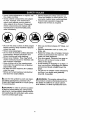
_,Look for this symbol to point out impor:ant safety precautions.
It means CAUtION!!! BECOME AWARE!!! YOUR SAFEFY IS INVOLVED.
A_.CAUTION:
In order to prevent
_,WARNING:
The engine exhaust from
this product contains chemicals known to
the State of California to cause cancer,
birth defects, or other reproductive
harm.
acciden-
al starting when setting up, transporting,
_djusting or making repairs always disconlect spark plug wire and place wire where
t cannot contact spark plug.
4
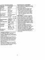
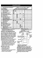
JRODUCT SPECIFICATIONS
MAINTENANCE
GASOLINE
CAPACITY
AND TYPE:
3.5 GALLONS
UNLEADED
REGULAR
A Sears Maintenance Agreement is available on this product. Contact your nearest
Sears store for details.
OIL TYPE
API-SF/SG/SH):
SAE 30
(above 32°F)
SAE 5W-30
CUSTOMER
;PARK PLUG:
GAP: .030")
_ALVE CLEARANCE:
RESPONSIBILITIES
• Read and observe the safety rules.
• Follow a regular schedule in maintaining, caring for and using your tractor.
• Follow the instructions under "Mainte-
(below 32°F)
91L CAPACITY:
AGREEMENT
3.0 PINTS
Champion RJ19LM
OR J19LM
INTAKE:
.004-.006
EXHAUST:
.007-.009
GROUND SPEED
MPH):
FORWARD:
REVERSE:
0- 5.5
0-2.4
TIRE PRESSURE:
FRONT: 14 PSI
REAR: 10 PSI
CHARGING
SYSTEM:
16 AMPS@3600
RPMS
BA]-IERY:
AMP/HR:
30
MIN. CCA:
240
CASE SIZE: UIR
BLADE BOLT
TORQUE:
27-35 F'[ LBS.
CONGRATULATIONS
on your purchase
of a Craftsman Tractor. It has been
designed, engineered and manufactured
to give you the best possible dependability
and performance.
Should you experience any problem you
cannot easily remedy, please contact your
nearest Sears Authorized Service Center.
We have competent, well-trained technicians and the proper tools to service or
repair this tractor.
Please read and retain this manual. The
instructions will enable you to assemble
and maintain your tractor properly. Always
observe the "SAFETY RULES".
nance" and "Storage"
owner's manual.
,_WARNING:
sections
of this
This _actor is equipped
with an internal combustion
engine and
should not be used on or near any unimproved forest-covered,
brush-covered
or
grass-covered
land unless the engine's
exhaust system is equipped with a spark
arrester meeting applicable local or state
laws (if any). If a spark arrester is used, it
should be maintained in effective working
order by the operator.
In the state of California the above is
required by law (Section 4442 of the
California Public Resources Code). Other
states may have similar laws. Federal
laws apply on federal lands. A spark
arrester for the muffler is available through
your nearest Sears Authorized Service
Center (See REPAIR PARTS section of
this manual).
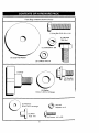
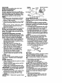
PartsBagcontentsshownfull size
(1) Hex Bolt 5/16-18 x 1-1/4
e
3/8-16 x 1
(1) Hex Bolt
(1) Lockwasher 3/8
(1) Large Flat Washer
(1) Locknut 5/16-18
(1) Knob
(1) Shoulder
Bolt 5/16-18
(1) Washer
17/32 x 1-3/16 x 12 Gauge
3/16 x 3/4 × 16 Gauge
(2) Washers
(2)
Lock #10
Washers
__
(2)
Weld
Nuts
#10
6
#10 x 5/8
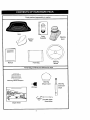
Partspackedseparatelyin carton
Seat
Video
Cassette
Mulcher
Plate
Steering
Boot
I
I
Manual
Steering
Wheel
Pa_s Bag
Parts Bag contents
not shown full size
L---------.J
Steering Wheel Adapter
Steering
Wheel Insert
<1
Steering
Extension
(2) Keys
Shaft
O
_(_) Latob
.'oo_
Assemblies
Slope Sheet
Your new tractor has been assembled at the factory with exception of those parts left
unassembled
for shipping purposes• To ensure safe and proper operation of your tractor
all parts and hardware you assemble must be tightened securely. Use the correct tools
as necessary to insure proper tightness. Review the video cassette before you begin.
TOOLS REQUIRED
FOR
ASSEMBLY
A socket wrench set will make assembly
easier. Standard wrench sizes you need
are listed below.
(1) 9/16" wrench
(1) 3/4" wrench
(2) 1/2" wrench
(1) Utility knife
(1)Pliers
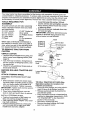
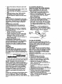
When right
this manual,
view, when
tion (seated
• Assemble large flat washer, 3/8 lock
washer, 3/8 hex bolt and tighten securely.
• Snap steering wheel insert into center
of steering wheel.
• Remove protective materials from tractor hood and grill_
IMPORTANT:
Check for and remove any
staples in skid that may puncture tires
where tractor is to roll off skid.
(1) 3/4" Socket w/
drive rachet
(1) Phillips
driver
Screw-
(1) Tire pressure
gauge
or left hand is mentioned in
it means, from your point of
you are in the operating posibehind the steering wheel).
Insert
, _
" _3/8
j
_a--_---_-_:,
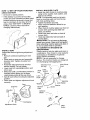
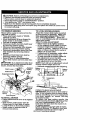
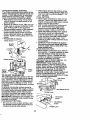
TO REMOVE TRACTOR FROM
CARTON
UNPACK CARTON
• Remove all accessible loose parts and
parts boxes from shipping carton (See
page 6).
• Cut, from top to bottom, along lines on
all four corners of shipping carton, and
lay panels flat.
• Check for any additional loose parts or
boxes and remove.
BEFORE
SKID
ATTACH
ROLLING
TRACTOR
3/8 Hex Bolt
Lockwasher
Steering
_
Steering
Wheel
Adapter
Extension
Shaft
Large F/at
Washer
oot
Tabs
_
_
5/16 Hex
Bolt
5/16 Lockn_//
OFF
Lower Steermg...._p...._
._,
o_ - _'--- -,
Shaft
,7
"q, _
-, ,
STEERING
WHEEL
L
ASSEMBLE
BOOT
EXTENSION
SHAFTAND
"-. _
....-.
• Slide extension shaft onto lower steering shaft• Align mounting holes in extension and lower shafts and install 5/16
Tab
, ,
Slots
TO ROLL TRACTOR OFF SKID (See
Operation section for location and
function of controls)
• Press lift lever plunger and raise attachment lift lever to its highest position.
• Release parking brake by depressing
clutch/brake pedal•
• Place freewheel control in freewheeling
position to disengage transmission
(See
"TO TRANSPORT"
in the Operation
section of this manual)•
• Roll tractor forward off skid.
• Remove banding holding discharge
hex bolt and Iocknut. Tighten securely.
IMPORTANT:
Tighten bolt and nut securely to 18-22 ft. Ibs. torque.
• Place tabs of steering boot over tab
slots in dash and push down to secure.
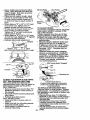
INSTALL STEERING WHEEL
• Position front wheels of the tractor so
they are pointing straight forward.
• Slide steering wheel adapter onto steering shaft extension.
• Position steering wheel so cross bars
are horizontal (left to right) and slide
inside boot and onto adapter.
guard up against tractor•
8
HOW iO SET UP YOUR
CHECK BATTERY
TRACTOR
• Lift hood to raised position.
• If this battery is put into service after
month and year indicated on label (label
located between terminals) charge battery for minimum of one hour at 6-10
amps. (See "BATTERY" in MAINTENANCE section of this manual for
charging instructions).
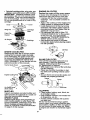
INSTALL
INSTALL MULCHER PLATE
• Install two latch hooks to mulcher plate
using screw, washer, lock washer, and
weld nut as shown.
NOTE: Pre-assemble weld nut to latch
hook by inserting weld nut from the top
with hook pointing down.
• Tighten hardware securely.
• Raise and hold deflector shield in upright position.
• Place front of mulcher plate over front of
mower deck opening and slide into
place, as shown_
• Hook front latch into hole on front of
mower deck.
• Hook rear latch into hole on back of
mower deck.
,ACAUTION:
Do not remove discharge
guard from mower. Raise and hold guard
when attaching mulcher plate and allow it
to rest on plate while in operation.
TO CONVERT TO BAGGING OR
DISCHARGING
SEAT"
Simply remove mulcher plate and store in
a safe place. Your mower is now ready for
discharging or installation of optional
grass catcher accessory.
NOTE: It is not necessary to change
blades. The mulcher blades are designed
for discharging and bagging also.
Adjust seat before tightening adjustment
knob.
• Remove cardboard packing on seat
pan.
• Place seat on seat pan and assemble
shoulder bolt. Tighten shoulder bolt
securely.
• Assemble adjustment knob and flat
washer loosely. Do not tighten.
• Lower seat into operating position and
sit on seat.
• Slide seat until a comfortable
position is
reached which allows you to press
clutch/brake
pedal all the way down.
• Get off seat without moving its adjusted
position.
• Raise seat and tighten adjustment knob
securely.
Seat
Weld Nut From
Hook Points
The Top
Down
Weld
Nut
"._j
\
Lock
Washer
Screw
Latch
Hook
Latch
Hook
IdNut
Lock Washer
Washer
Washer
Seat Pan
Mulcher
Plate
Shoulder
Bolt
¥._Screw
Deflector
,_
Flat Washer
Adjustment Knob
,_r
9
Latch
Hooks
CHECKTIREPRESSURE
The tires on your tractorwereoverinflated
v" CHECKLIST
PLEASE REVIEW
CHECKLIST:
at the factory for shipping purposes.
Correct tire pressure is important for best
cutting performance.
• Reduce tire pressure to PSI shown in
"PRODUCT SPECIFICATIONS"
on
I#' All assembly instructions have been
completed.
v' No remaining loose parts in carton.
v' Battery is properly prepared and
charged.
(Minimum 1 hour at 6 amps).
page 5 of this manual.
CHECK
DECK LEVELNESS
v' Seat is adjusted comfortably
tightened securely.
For best cutting results, mower housing
should be properly leveled. See "TO
LEVEL MOWER ROUSING" in the
Service and Adjustments
manual.
CHECK FOR PROPER
ALL BELTS
v'
section of this
POSITION
THE FOLLOWING
and
All tires are prop, erly inflated. (For
shipping purposes, the tires were
overinflated at the factory).
_" Be sure mower deck is properly leveled
side-to-side/front-to-rear
for best
OF
cutting results. (Tires must be properly
inflated for leveling).
is' Check mower and drive belts. Be sure
See the figures that are shown for replacing motion and mower blade drive belts in
the Service and Adjustments sectoin of
this manual. Verify that the belts are routed correctiy.
CHECK BRAKE SYSTEM
they are routed properly around pulleys
and inside all belt keepers.
v" Check wiring. See that all connections
are still secure and wires are properly
clamped.
After you learn how to operate your tractor, check to see that the brake is propedy
adjusted. See "TO ADJUST BRAKE" in
the Service and Adjustments section of
this manual.
Before driving tractor, be sure freewheel control is in drive position.
WHILE LEARNING HOW TO USE YOUR
TRACTOR,
PAY EXTRAATTENTION
TO
THE FOLLOWING
IMPORTANT
ITEMS:
,/ Engine oil is at proper level.
V" Fuel tank is filled with fresh, clean,
regular unleaded gasoline.
,/ Become familiar with all controls - their
•/
,/
10
location and function. Operate them
before you start the engine.
Be sure brake system is in safe operating condition.
It is important to purge the transmission before operating your tractor for
the first time. Follow proper starting
and transmission
purging instructions
(See "TO START ENGINE" and
"PURGE TRANSMISSION"
in the Operation section of this manual).
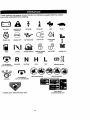
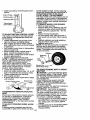
Thesesymbolsmay appearon yourtractoror in literature
Learn and understand
BATTERY
CAUTION OR
WARNING
FUEL
CHOKE
REVERSE
(_)
IGNITION
DANGER,
REVERSE
FORWARD
MOWER HEIGHT
R N
ATTACHMENT
CLUTCH ENGAGED
supplied
with the product.
their meaning.
NEUTRAL
_
FAST
PARKING BRAKE
LOCKED
H
L
HIGH
LOW
KEEP AREA CLEAR
ATTACHMENT
CLUTCH DISENGAGED
SLOW
UNLOCKED
MOWER LIFT
PARKING BRAKE
SLOPE HAZARDS
(SEE SAFETY RULES SECTION)
FREE WHEEL
(AutomaticModelsonly)
KEEP HANDS AND FEET AWAY
11
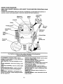
KNOW YOUR TRACTOR
READ THIS OWNER'S
TRACTOR
MANUAL
AND SAFETY
RULES
BEFORE
OPERATING
YOUR
Compare the illustrations with your tractor to familiarize yourself with the locations of
various controls and adjustments. Save this manual for future reference,
Attachment
Clutch Lever
Ignition
Switch
Light Switch
Position
Amme_r
Choke
Throttle Control
Lift Lever
Plunger
Clutch/Brake
Pedal
Attachment
Lift Lever
Height
Adj_
Knob
Parking Brake
Motion
Control Lever
Freewheel
Control
Our tractors
conform to the safety standards of the American
National Standards Institute.
AI-I'ACHMENT CLUTCH LEVER: Used to
engage the mower blades, or other attachments
mounted to your tractor.
LIGHT SWITCH: Turns the headlights on and
off.
HEIGHT ADJUSTMENT KNOB: Used to adjust
the mower cutting height.
MOTION CONTROL LEVER: Selects the
speed and direction of the tractor.
ATTACHMENT LIFT LEVER: Used to raise and
lower the mower deck or other attachments
mounted to your tractor.
LIFT LEVER PLI,INGER: Used to release
attachment lift lever when changing its position.
IGNITION SWITCH: Used for starting and stopping the engine.
AMMETER: Indicates battery charging (+) or
discharging (-).
PARKING BRAKE: Locks clutch/brake into the
brake position.
CHOKE CONTROL: Used when starting a cold
engine.
THROTTLE CONTROL: Used to control engine
speed.
CLUTCH/BRAKE PEDAL: Used for declutching and braking the tractor and starting the
engine.
FREEWHEEL CONTROL: Disengages transmission for pushing or slowly towing the tractor
with the engine off.
12
I_
eyes, which can result in severe eye damage. Always wear safety glasses
or eye shields while operating your tractor or performing any adjustments or
repairs.
We recommend
a wide
mask
over spectacles,
he operation
of any tractor
can vision
result safety
in foreign
objects
thrown into or
thestandard safety glasses.
HOW TO USE YOUR TRACTOR
Your tractor is equipped with an operator
presence sensing switch. When engine is
running, any attempt by the operator to
leave the seat without first setting the
parking brake will shut off the engine,
TO SET PARKING BRAKE
• Depress clutch/brake pedal into full
"BRAKE" position and hold.
• Place parking brake lever in "ENGAGED" position and release pressure
from clutch/brake pedal. Pedal should
remain in "BRAKE" position. Make sure
parking brake will hold tractor secure.
Choke
Attachment Clutch
Control
Lever "Engaged"
Throttle _..._.((,_._--_sitio
n
ControIx. \_..'_--,_
_
=Disengaged"
Height
"__:_
...Position
Adjustment L_ _ _ _!L_e,
,/
Knob
_,'_.,._'\ ', _\ ,!_" /Parking Brake
Brake" -----_._'_,_
_"_'.}/ "Engaged"
Position
-_, _-" =.:'-'_"_ _"
Position
Clutch"
Pedal "Ddve"
_,
Position
Motion Control
M°vtie°rn
Contr(
_
_"
Position
STOPPING
MOWER BLADES • To stop mower blades, move attachment clutch lever to "DISENGAGED"
position,
GROUND DRIVE • To stop ground drive, depress
clutch/brake pedal into full "BRAKE"
position,
• Move motion control lever to neutral (N)
position,
IMPORTANT: The motion control lever
does not return to neutral (N) position
when the clutch/brake pedal is depressed.
ENGINE • Move throttle control to slow position,
NOTE: Failure to move throttle control to
slow position and allowing engine to idle
before stopping may cause engine to
"backfire".
• Turn ignition key to "OFF" position and
remove key. Always remove key when
leaving tractor to prevent unauthorized
use.
• Never use choke to stop engine.
IMPORTANT:
Leaving the ignition switch
in any position other than "O_FF" will cause
the battery to be discharged, (dead).
NOTE: Under certain conditions when
tractor is standing idle with the engine running, hot engine exhaust gases may
cause "browning" of grass. To eliminate
this possibility, always stop engine when
s_opping tractor on grass areas.
A CAUTION.
Always stop tractor cornpletely, as described above, before leaving
the operator's position; to empty grass
catcher, etc.
THROTTLE
CONTROL
Always operate engine at full throttle.
,, Operating engine at less than full throt• tie reduces the battery charging rate.
Full throttle offers the best bagging and
mower performance.
CHOKE CONTROL
Use choke control whenever you are starting a cold engine. Do not use to start a
warm engine.
• To engage choke control, pull knob out.
Slowly push knob in to disengage.
TO MOVE FORWARD AND BACKWARD
The direction and speed of movement is
controlled by the motion control lever.
• Start tractor with motion control lever in
neutral (N) position.
• Release parking brake and clutch/brake
pedal.
• Slowly. move motion control lever to
desired position.
NOTE: The effort to move the motion control lever will reduce after the first few
hours of use. This is normal.
TO ADJUST MOWER cu'n'ING
HEIGHT
The cutting height is controlled by turning
the height adjustment knob in desired
direction.
• Turn knob clockwise (C) to raise cutting
height.
* ,Turn knob counterclockwise (,.3) to
lower cutting height.
The cutting height range is approximately
1-1/2" to 44. _he heigfits are measured
from the ground to the blade tip with the
engine not running. These heights are approximate and may vary_ depending upon
soil conditions, height of grass and-types
of grass being mowed.
• The average lawn should be cut to
approximately 2-1/2 inches during the
cool season and to over 3 inches during
hot months. For healthier and better
looking lawns, mow often and after
13 moderate growth.
• For best cutting performance, grass
over 6 inches in height shouldbe
mowed twice. Make the first cut relatively high; the second to desired height.
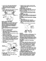
TO ADJUST GAUGE WHEELS
• Move motion control lever to neutral (N)
position.
IMPORTANT: The motion control lever
does not return to neutral (N) position
when the clutch/brake pedal is depressed.
• To restart movement, slowly release
parking brake and clutch/brake pedal.
• Slowly move motion control lever to
slo_Nest setting.
• Make all turns slowly.
Gauge wheels are properly adjusted
when they are slightly off the ground when
mower is at the desired cutting height in
operatingposition.
Gauge wheels then
keep the deck in proper position to help
prevent scalping in most terrain conditions.
• Adjust gauge wheels with tractor on a
flat level surface.
• Adjust mower to desired cutting height
(See "TO ADJUST MOWER CUI-rlNG
HEIGHT" in the Operation section of
this manual).
• With mower in desired height of cut position, gauge wheels should be assembled so they are slightly off the ground.
Install gauge wheel in appropriate hole
with shoulder bolt, 3/8 washer, and 3/816 Iocknut and tighten securely.
• Repeat for opposite side installing
gauge wheel in same adjustment hole.
3/8-16
Attachment Clutch
Lever "En(
Position
=Disengaged"
Low
Position
TO TRANSPORT
When pushing or towing your tractor, be
sure to disengage transmission by placing
freewheel control in freewheeling
position. FTeewheel control is located at the
rear drawbar of tractor.
• Raise attachment lift to highest position
with attachment lift control.
• Pull freewheel control out and down into
the slot and release so it is held in the
disengaged position.
• Do not push or tow tractor at more than
two (2) MPH.
• To reengage transmission, reverse
above procedure.
o_
Locknut _
-.
Gauge Wheel
Mounting
3/8 Washer
Gaug_
Attachment Lift
Lever High Position
""" J
Shoulder
Bolt
TO OPERATE MOWER
Your tractor is equipped with an operator
presence sensing switch. Any attempt by
the operator to leave the seat with the
engine runnmgand the attachment clutch
engaged will shut off the engine.
• Select desired height of cut.
• Lower mower with attachment lift control.
• Start mower blades by engaging attachment clutch control.
• TO STOP MOWER BLADES - disengage attachment clutch control.
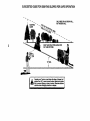
_ OPERATE ON HILLS
CAUTION:
Do not drive up or down
hills with slopes greater than 15 ° and do
not drive across any slope. Use the slope
guide provided at the back of this manual.
• Choose the slowest speed before starting up or down hills.
• Avoid stopping or changing speed on
hills.
If slowing is necessary, move throttle
control lever to slower position.
If stopping is absolutely necessary, pusl'f
clutch/brake pedal quickly to brake position and engage parking brake,
NOTE: To protect hood from damage
when transporting your tractor on a truck
or a trailer, be sure heed is closed and
secured to tractor. Use an appropriate
means of tying hood to tractor (rope, cord,
etc.).
TOWING CARTS AND OTHER
ATTACHMENTS
Tow only the attachments that are recommended by and comply with specifications
of the manufacturer of your tractor. Use
common sense when towing. Too heavy of
a load, while on a slope, is dangerous.
Tires can lose traction with the ground and
cause you to lose control of your tractor.
14
BEFORE STARTING THE ENGINE
CHECK ENGINE OIL LEVEL
• Move attachment clutch to "DISENGAGED" position.
Move throttle control to fast position
Pull choke control out for a cold engine
start attempt. For a warm engine start
attempt the choke control may not be
needed.
NOTE: Before starting, read the warm and
cold starting procedures below.
• Insert key into ignition and turn key
clockwise to "START" position and
release key as soon as engine starts.
Do not run starter continuously
for more
than fifteen seconds per minute. If the
engine does not start after several
attempts, push choke control in, wait a
few minutes and try again. If engine still
does not start, pull the choke control out
and retry.
WARM WEATHER STARTING (50 ° F
• The engine in your tractor has been
shipped, from the factory, already filled
with summer weight oil.
• Check engine oil with tractor on level
ground.
• Remove oil fill cap/dipstick
and wipe
clean, reinsert the dipstick and screw
cap tight, wait for a few seconds,
remove and read oil level. If necessary,
add oil until "FULL" mark on dipstick is
reached. Do not overfill.
• For cold weather operation you should
change oil for easier starting (See "OIL
VISCOSITY CHART" in the Maintenance section of this manual).
• To change engine oil, see the Maintenance section in this manual.
ADD GASOLINE
• Fill fuel tank. Use fresh, clean, regular
AND ABOVE)
When engine starts, slowly push choke
unleaded gasoline with a minimum of 87
control in until the engine begins to run
octane. (Use of leaded gasoline will
smoothly. If the engine starts to run
increase carbon and lead oxide
roughly, pull the choke control out slightdeposits and reduce valve life). Do not
ly
for a few seconds and then continue
mix oil with gasoline. Purchase fuel in
to push the control in slowly.
quantities that can be used within 30
• The attachments
and ground drive can
days to assure fuel freshness.
now
be
used.
If
the
engine does not
IMPORTANT: When operating in temperaaccept the load, restart the engine and
tures below 32°F(0°C), use fresh, clean
allow it to warm up for one minute using
winter grade gasoline to help insure good
the choke as described above.
cold weather starting.
AILWARNING:
Experience indicates that
COLD WEATHER STARTING (50 ° F AND
alcohol blended fuels (called gasohol or
BELOW)
using ethanol or methanol) can attract
• When engine starts, slowly push choke
control in until the engine begins to run
moisture which leads to separation and
formation of acids during storage. Acidic
smoothly. Continue to push the choke
gas can damage the fuel system of an
control in small steps allowing the
engine while in storage. To avoid engine
engine to accept small changes in
speed and load, until the choke control
problems, the fuel system should be empis fully in. If the engine starts to run
tied before storage of 30 days or longer.
Drain the gas tank, start the engine and let
roughly, pull the choke control out slightit run until the fuel lines and carburetor are
ly for a few seconds and then continue
empty. Use fresh fuel next season. See
to push the control in slowly. This may
Storage Instructions for additional informarequire an engine warm-up period from
several seconds to several minutes,
tion. Never use engine or carburetor
depending on the temperature.
cleaner products in the fuel tank or permaAUTOMATIC TRANSMISSION
WARM-UP
_nct damage may occur.
AUTION: Fiflto bottom of gas tank
• Before ddvincj the unit in cold weather,
filler neck. Do not overfill. Wipe off any
the transmisston should be warmed up
as follows:
spilled oil or fuel. Do not store spill or use
gaso ne near an open f ame.
• Be sure the tractor is on level _]round.
Place the motion control lever =nneuTO START ENGINE
tral.
Release the parking brake and
When starting the engine for the first time
let
the
cltJtch/brake slowly return to
or if the engine has run out of fuel, it will
operating position.
take extra cranking time to move fuel from
• Allow one minute for transmission to
the tank to the engine.
• Be sure freewheel control is in the
warm up. This can be done during the
engine warm up period.
transmission engaged position.
• The attachments can be used during
• Sit on seat in operating position,
the engine warm-up period after the
depress clutch/brake pedal and set
transmission has been warmed up and
parking brake.
may require the choke control be pulled
• Place motion control lever in neutral (N)
position.
15
out slightly.
NOTE:A highaltitude(above3000 feet)
• Your tractor is now purged and ready for
normal operation.
MOWING
TIPS
• Tire chains cannot be used when the
mower housing is attached to tractor.
• Mower should be properly leveled for
best mowing performance. See "TO
LEVEL MOWER HOUSING" in the
Service and Adjustments section of this
manual.
• The left hand side of mower should be
used for trimming.
• Drive so that clippings are discharged
onto the area that has been cut. Have
the cut area to fife right of the tractor.
This will result in a more even distribution of clippings and more uniform cutting.
• When mowing large areas, start by turning to the right so that clippings will discharge away from shrubs, fences, driveways, etc. After one or two rounds, mow
in the opposite direction making left
hand turns until finished.
• If grass is extremely tall, it should be
mowed twice to reduce load and possible fire hazard from dried clippings.
Make first cut relatively high; the second
to the desired height.
• Do not mow grass when it is wet. Wet
grass will plug mower and leave undesirable clumps. Allow grass to dry
before mowing.
• Always operate engine at full throttle
when mowing to assure better mowing
performance and proper discharge of
material. Regulate ground speed by selecting a low enough gear to give the
mower the best cutting performance as
well as the quality of cut desired.
• When operating attachments, select a
ground speed that will suit the terrain:,
and give best performance of the attachment being used.
or in cold temperatures (below 32 F) the
carburetor fuel mixture may need to be
adjusted for best engine performance.
See "TO ADJUST CARBURETOR"
in the
Service and Adjustments section of this
manual.
P_RGE TRANSMISSION
CAUTION.
Never engage or disengage freewheel lever wh_le the engine is
running.
To ensure proper operation and performance, it is recommended
that the transmission be purged before operating tractor
for the first time. This procedure wm
remove any trapped air inside the transmission which may have developed during
shippingof your tractor.
IMPORTANT: Should your transmission
require removal for service or replacement, it should be purged after reinstallat=on before operating the tractor.
• Place tractor safely on level surface with
engine off and parking brake set.
• Disengage transmission by placing freewheel control in freewheeling
position
(See "TO TRANSPORT"
in this section
of manual).
• Sitting in the tractor seat, start engine.
After the engine is running, move throttle control to slow position. With motion
control lever in neutral (N) position,
slowly disengage clutch/brake pedal.
• Move motion control lever to full forward
position and hold for five (5) seconds.
Move lever to full reverse position and
hold for five (5) seconds. Repeat this
procedure three (3) times.
NOTE: During this procedure there will be
no movement of dnve wheels. The air is
being removed from hydraulic drive system.
• Move motion control lever to neutral (N)
position. Shut off engine and set parking
brake.
• Engage transmission by placing freewhee/control in driving position (See
"TO TRANSPORT"
in this section of
manual).
• Sitting in the tractor seat, start engine.
After the engine is running, move throttle control to half (1/2) speed. With
motion control lever in neutral (N) position, slowly disengage clutch/brake
pedal.
• Slowly move motion control lever forward; after the tractor moves approximately five (5) feet, slowly move motion
control lever to reverse position. After
the tractor moves approximately five (5)
feet return the motion control lever to
the neutral (N) position. Repeat this procedura with the motion control lever
three (3) times.
"
li
,
16
4
.
MULCHING
MOWING
TIPS
IMPORTANT: For best performance, keep
mower housing free of built-up grass and
trash. Clean after each use.
• The special mulching blade will recut
the grass clippings many times and
reduce them in size so that as they fall
onto the lawn they will disperse into the
grass and not be noticed. Also, the
mulched grass will biodegrade
quickly
to provide nutrients for the lawn. Always
mulch with your highest engine (blade)
speed as this will provide the best recutting action of the blades.
• Avoid cutting your lawn when it is wet.
Wet grass tends to form clumps and
interferes with the mulching action. The
best time to mow your lawn is the early
afternoon. At this time the grass has
dried and the newly cut area will not be
exposed to the direct sun.
• For best results, adjust the mower cutting height so that the mower cuts off
only the top one-third of the grass
blades. For extremely heavy mulching,
reduce your width of cut on each pass
and mow slowly.
• Certain types of grass and grass conditions may require that an area be
mulched a second time to completely
hide the clippings. When doing a second cut, mow across or perpendicular to
the first cut path.
• Change your cutting pattern from week
to week, Mow north to south one week
then change to east to west the next
week. This will help prevent matting and
graining of the lawn.
•,
17
f i
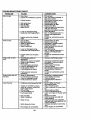
AsF'LLyouMAINTENANCE
SCHEDULEiN
DATEScOMPLETE
__d_"
.EGU S
RERV,CE
c__o,o.o.,.,.°
'_'_
Y
'_'_''_°e'_-'_
-"_'_I"_._._'_,_".,_=_7;_"':
_',_o_;
_,,o_
OATES
Check Tire Pressure
T
R
Check Operator Presence and
interlock Systems
Cr.Bck for Loose Fasteners
T
Lubrication Chart
0
A
Check
Battery Level
Sharpen/Replace
Mower Blades
Clean Battery and Terminals
R
Check
Transaxla
;V'
11_7
ll_e
_4
l# /
Cooling
Adjust Blade BaR(s) Tension
Ks
v',
Adjust Motion Drive BaR(S) Tension
Check Engine Oil Level
_
Change Engine Oil
!1_1.,_
I_
E
Clean Air Filter
Ik_2
N
Clean Air Screen
_2
IG
Inspect Muffler/Spark Arrester
N
Replace Oil Filter (If equipped)
Clean Engine Cooling Fins
Replace Spark plug
._.=
Replace Air Filter Paper Cartridge
1_2
S
Ik/
_2
I_
Replace Fuel Filter
Ikf
1 - Change mcce often when operating under a heavy load o_"in high ambient temperatures,
2 - Service more often when c_perating in dirty or dusty cond;_ons.
3 - If equipped with oil filter, change oll eveP/50
hours.
g - If equipped with ao*jus,_able system.
6 ° Not required if equipped with mmintenance-free
batter
7 - Tighten front exle _
bolt to 35 ft,- f_s. meximurn,
4 - Replace oiades rnoceoften when mowing in sandy soil.
DO not or=tighten.
GENERAL RECOMMENDATIONS
LUBRICATION
The warranty on this tractor does not cover
items that have been subjected to operator
abuse or negligence. To receive full value
from the warranty, operator must maintain
Zerk
tractor as instructed in this manual. Some
adjustments will need to be made periodically to propedy maintain your tractor.
All adjustments in the Service and
Adjustments
be checked
• Once
spark
check
spark
0
Bearin,
section of this manual should
at least once each season.
a year you should replace the
plug, clean or replace air filter, and
blades and belts for wear. A new
plug and clean air filter assure
•
•
•
•
EACH
CHART
Zerk
Wheel
Bearing
Zerk
Clutch
Pivot(s)
_SAE
30 or
1,0w30Grease
Motor OIL
General
Purpose
0 Refer to Maintenance "Engine" Section
USE
Check engine oil level.
Check brake operation.
Check tire pressure.
Check operator presence and interlock
systems for proper operation.
• Check for loose fasteners.
•
0 Engine
proper air-fuel mixture and help your
engine run better and last longer.
BEFORE
I_
IMPORTANT:
Do not oil or grease the
pivot points which have special nylon bearings. Viscous lubricants will attract dust
and dirt that will shorten the life of the selflubricating bearings, if you feel they must
be lubricated, use only a dry, powdered
graphite type lubricant spanngly.
18
TRACTOR
Always observe safety rules when performing any maintenance.
BRAKE OPERATION
Mandrel Assembly
Blade
Center
Hole
If tractor requires more than six (6) feet
Flat Washer
stopping distance at high speedin highest
gear then brake must be adjusted. (See
Lock
,_,,,
Star
=TO ADJUST BRAKE" in the Serv ce and
Washer"-,_:. _ _.
Adjustments section of this manual).
_Hex
Bolt (C
TIRES
TO SHARPEN
BLADE
• Maintain proper air pressure in all tires
(See =PRODUCT SPECIFICATIONS"
NOTE: We do not recommend sharpensection of this manual).
ingblade
but if you do, be sure the blade
isbalanced.
• Keep tires free of gasoline, oil, or insect
control chemicals which can harm rubCare should be taken to keep the blade
balanced. An unbalanced blade will cause
ber.
excessive vibration and eventual damage
• Avoid stumps, stones, deep ruts, sharp
to mower and engine.
objects and other hazards that may
• The blade canbe sharpened with a file
cause tire damage.
or on a grinding wheel. Do not attempt
NOTE: To seal tire punctures and prevent
to sharpen while it is on the mower.
flat tires due to slow leaks, tire sealant
• To check blade balance, you will need a
may bepurchased from your local parts
5/8" diameter steel bolt, pin, or a cone
dealer. Tire sealant also prevents hre dry
rot and corrosion.
balancer. (When using a cone balancer,
follow the instructions supplied with balOPERATOR
PRESENCE SYSTEM
ancer).
Be sure that operator presence and interNOTE:
Do not use a nail for balancing
lock systems are working properly. Ifyour
blade. The lobes of the center hole may
tractor does not function as described
appear to be centered, but are not.
below, repair the problem immediately.
• Slide blade onto an unthreaded portion
• The engine should not start unless the
of the steel bolt or pin and hold the bolt
clutch/brake pedal is fully depressed
or pin parallel with the ground. If blade
and attachment clutch control is in the
is balanced, it should remain in a horidisengaged position.
zontal position. If either end of the blade
• When the engine is running, any
moves downward, s._arpen the heavy
attempt by the operator to leave the
end until the blade is balanced.
seat without first setting the parking
brake should shut off the engine.
• When the engine is running and the
attachment clutch is engaged, any
attempt by the operator to leave the
seat should shut off the engine.
or Pin
• The attachment clutch should never
BATTERY
operate unless the operator is in the
Your tractor has a battery charging system
seat.
which is sufficient for normal use.
BLADE CARE
However, periodic charging of the battery
For best results mower blades must be
with an automotive charger will extend its
kept sharp. Replace bent or damaged
life.
blades.
• Keel_ battery and terminals clean.
BLADE REMOVAL
• Keep battery bolts tight.
• Raise mower to highest position to allow
• Keep small vent holes open.
access to blades.
• Recharge at 6-10 amperes for 1 hour.
• Remove hex bolt, lock washer and flat
NOTE: The original equipment battery on
washer securing blade.
your tractor is maintenance free. Do not
• Install new or resharpened blade with
attempt to open or remove caps or covers.
trailing edge up towards deck as shown.
Adding or checking level of electrolyte is
IMPORTANT:
To ensure proper assembly,
not necessary.
TO CLEAN BATTERY AND TERMINALS
center hole in blade must align with star
on mandrel assembly.
Corrosion and dirt on the battery and ter• Reassemble hex bolt, lock washer and
minals can cause the battery to "leak"
flat washer in exact order as shown.
power.
• Tighten bolt securely (27-35 Ft. Lbs.
• Remove terminal guard.
torque).
• Disconnect BLACK battery cable first
then RED battery cable and remove
IMPORTANT:
Blade bolt is grade 8 heat
treated.
19
battery from tractor.
•
Rinse the battery with plain water and
dry.
• Clean terminals and battery cable ends
with wire brush until bnght,
• Coat terminals with grease or petroleum
je y.
• Reinstall battery (See =REPLACING
BATTERY" in the SERVICE AND
ADJUSTMENTS
section of this menual).
V-BELTS
Check V-belts for deterioration and wear
after 100 hours of operation and replace if
necessary. The belts are not adjustable.
Replace belts if they begin to slip from
wear.
TRANSAXLE
COOLING
The transmission fan and cooling fins
should be kept clean to assure proper
coolinq.
Do no[attempt to clean fan or transmission while engine is running or while the
transmission ts hot.
* Inspect cooling fan to be sure fan
blades are intact and clean.
° Inspect cooling fins for dirt, grass clippings and other materials. To prevent
damage to seals, do not use compressed air or high pressure sprayer to
clean cooling fins.
TRANSAXLE
PUMP FLUID
The transaxle was sealed at the factory
and fluid maintenance is not required for
the life of the transaxle. Should the
transaxle ever leak or require servicing,
contact your nearest authorized service
center.
ENGINE
LUBRICATION
Only use high quality detergent oil rated
with API service classification SF, SG or.
SH. Select the oil's SAE viscosity grade
according to your expected operating temperature.
sacwscom_ GP._ES
+tO.
TEMPERATURE
tO"
20.
R/tiC E ANTICJPATED BEFORE NEXT OIL CHANGE
NOTE: Although multi-viscosity oils
(5W30, 10W30 etc.) improve starling in
cold weather, these multi-viscosity o=lswill
result in increased oil consumption when
used above 32°F. Check your engine oil
level more frequently to avoid possible
engine damage from running low on oil.
Change the od after every 50 hours of
operation or at least once a year if the
tractor is not used for 50 hours in one
ehar.
eck the
TO CHANGE ENGINE OIL
Determine temperature range expected
before oil change. All oil must meet API
service classification SF, SG or SH.
• Be sure tractor is on level surface.
• Oil will drain more freely when warm.
Catch oil in a suitable container.
• Remove oil fill cap/dipstick. Be careful
not to allow dirt to enter the engine
when changing oil.
• Remove drain plug.
After oil has drained completely, replace
oil drain plug and tighten securely.
• Refill engine with oil through oil fill dipstick tube. Pour slowly. Do not overfill.
For approximate capacity see =PRODUCT SPECIFICATIONS"
section of this
manual.
• Use gauge on oil fill cap/dipstick for
checking level. Be sure dipstick cap is
tightened securely for accurate reading.
Ke'ep oil at =FULL" line on dipstick.
/_
Oil Drain
Plug_
_)----_
Air Screen
_..._..//
_
Oil Fill Cap/Dips_ck f
o_
__.
CLEAN AIR SCREEN
Air screen must be kept free of dirt and
chaff to prevent engine damage from overheating. Clean with a wire brush or compressed air to remove dirt and stubborn
dried gum fibers.
AIR FILTER
Your engine will not run properly using a
dirty air filter. Clean the foam pre-cleaner
after every 25 hours of operation or every
season. Service paper cartridge every
100 hours of operation or every season,
whichever occurs first.
Service air cleaner more often under dusty
conditions.
• Remove knob(s) and cover.
TO SERVICE PRE-CLEANER
• Slide foam pre-cleaner off cartridge.
Wash it in liquid detergent and water.
Squeeze it dry in a clean cloth.
• Saturate it in engine oil. Wrap it in
clean, absorbent cloth and squeeze to
remove excess oil.
• If very dirty or damaged, replace precleaner.
crankcase oil level before starting the engine and after each eight (8)
hours of operation. Tighten oil fill cap/dipstick securely each time you check the oil 20
level.
• Reinstall
over cartridge.
Reinstall pre-cleaner
cover and secure
with knob(s).
TO SERVICE CARTRIDGE
Carefully remove cartridge to prevent
Remove
debr
s from
wingentering
nuts and
carburetor.
cartridge plate.
Clean cartridge by tapping gently on flat
surface. If very dMrty or damaged,
replace cartridge.
ENGINE
• Reinstall cartridge plate, wing nuts, precleaner, cover and secure with knob(s).
IMPORTANT:
Petroleum solvents, such
as kerosene, are not to be used to clean
the cartridge. They may cause deterioration of the cartridge. Do not oil cartridge.
Do not use pressurized air to clean or dry
cartridge.
Knob_
OIL FILTER
Replace the engine oil filter every season
or every other oil change if the tractor is
used more than 100 hours in one year.
• Unscrew old filter by turning counterclockwise. Use a suitable container to
catch oil.
• Apply a thin coating of new engine oil to
rubber gasket on replacement oil filter.
• Install replacement oil filter by turning
clockwise until rubber gasket contacts
mounting surface, then tighten filter an
additional 1/2to 3/4 turn.
• Fill crankcase with new oil (See "TO
CHANGE ENGINE OIL" in this section
of this manual). For approximate
capacity see "PRODUCT SPECIFICATIONS" section of this manual.
• Start engine and check for oil leaks.
Correct any leaks before placing engine
into full operation.
Cover
Wing Nut
Plate
Foam PreCleaner
Air Screen
Oil Filter
ENGINE COOLING FINS
Remove any dust, dirt or oil from engine
cooling fins to prevent engine damage
from overheating. Air guide covers must
be removed. Remove side panels and
hood (See "TO REMOVE HOOD AND
GRILL ASSEMBLY" in the Service and Adjustments section of this manual).
IN-LINE FUEL FILTER
The fuel filter should be replaced once
each season. If fuel filter becomes
clogged, obstructing fuel flow to carburetor, replacement is required.
• With engine cool, remove filter and plug
fuel line sections.
• Place new fuel filter in position in fuel
line with arrow pointing towards carburetor.
• Be sure there are no fuel line leaks and
clamps are propedy positioned.
Top Air Guid_.,,.
Engine Cooling
_
Filter
Air Guide Cover
(Both Sides)
CLEANING
• Clean engine, battery, seat, finish, etc.
of all foreign matter.
• Keep finished surfaces and wheels free
of all gasoline, oil, etc.
• Protect painted surfaces with automotive type wax.
We do not recommend using a garden
hose to clean your tractor unless the electrical system, muffler, air filter and carburetor are covered to keep water out. Water
in engine can result in a shortened engine
life.
MUFFLER
Inspect and replace corroded muffler and
spark arrester (if equipped) as it could create a fire hazard and/or damage.
SPARK
PLUGS
Replace spark plugs at the beginning of
each mowing season or after every 100
hours of operation, whichever occurs first.
Spark plug type ar_dqap settinqare
shown in "PRODUCTSPECIFI_3ATIONS"
on page 5 of this manual.
21
,A=CAUTION: Before performing any service or adjustments:
• Depress clutch/brake pedal fully and set parking brake.
• Place motion control lever in neutral (N) position.
• Place attachment clutch in "DISENGAGED"
position.
i
Make
sure thekey
blades
moving key.
parts have completely stopped.
urn ignition
"OFF"and
andallremove
Disconnect spark plug wire from spark plug and place wire where it cannot come
In contact with plug.
TO REMOVE
MOWER
Mower will be easier to remove from the
right side of tractor.
• Place attachment clutch in "DISENGAGED" position.
• Move attachment lift lever forward to
lower mower to its lowest position.
.- Roll belt off engine pulley.
Disconnect clutch rod from clutch lever
by removing retainer spring.
• Disconnect anti-swaybar from chassis
bracket by removing retainer spring.
• Disconnect suspension arms from rear
deck brackets by removing retainer
springs.
• Disconnect front links from deck by
removing retainer springs.
• Raise lift lever to raise suspension
arms. Slide mower out from under tractor.
IMPORTANT:
If an attachment other than
the mower deck is to be mounted on the
tractor, remove the front links.
Retainer
Clutch
Suspension Arms
Engine
Pulley
Front
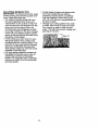
TO LEVEL MOWER HOUSING
Adjust the mower while tractor is parked
on level ground or driveway. Make sure
tires areproperly
inflated (See "PRODUCT SPECIFICATIONS").
If tires are
over or underinflated, you will not properly
adjust your mower.
SIDE-TO-SIDE
ADJUSTMENT
Raise mower to its highest position.
At the midpoint of both sides of mower,
measure height from bottom edge of
mower to ground.
Distance "A" on both
sides of mower should be the same or
within 1/4" of each other.
• If adjustment is necessary, make adjustment on one side of mower only.
• To raise one side of mower, tighten lift
link adjustment nut on that side.
• To lower one side of mower, loosen lift
link adjustment nut on that side.
NOTE: Each full turn of adjustment nut will
change mower height abbut 1/8".
• Recheck measurements
Bottom r---r
otcu
after adjusting.
°o°
rou Une7""]-F
Bottom
Suspension
Arm
ustment Nut
Retainer
Spring
Anti-Swaybar
TO INSTALL
MOWER
• Raise attachment lift lever to its highest
position.
• Slide mower under tractor with discharge guard to right side of tractor.
• Lower lift lever to its lowest position.
Install mower in reverse order of
removal instructions.
FRONT-TO-BACK
ADJUSTMENT
IMPORTANT:
Deck must be level side-toside. If the followinqfront-to-back
adjustment is necest_ary, be sure to adjust both
front links equally
so mower will stay
level side-to-side.
To obtain the best cutting results, the
mower housing should be aajusted so that
the front is approximately 1/8 TM to 1/2"
lower than the rear when the mower is in
its highest position.
Check adjustment on right side of tractor.
Measure distance "D" directly in front and
behind the mandrel at bottom edge of
22 mower housing as shown.
• Before making any necessary adjustments, check that both front links are
equal in length. Both links should be
approximately 10-3/8 =.
• If links are not equal in length, adjust
one link to same length as other link.
• To lower front of mower loosen nut =E"
on both front links an equal number of
turns.
• When distance =D" is 1/8" to 1/2" lower
at front than rear, tighten nuts "P
against trunnion on both front links.
• To raise front of mower, loosen nut =P
from trunnion on both front links.
Tighten nut =E" on both front links an
equal number of turns.
• When distance =D" is 1/8" to 1/2" lower
at front than rear, tighten nut "P against
trunnion on beth front links.
• Recheck side-to-side adjustment.
__ndrel
Both Front Links Should be Equal in Length
Mandrel
Pulle,
TO ADJUST BRAKE
Your tractor is equipped with an adjustable
brake system whiqh is mounted on the
side of the transaxle.
If tractor requires more than six (6) feet
stopping distance at high speed in highest gear, then brake must be adjusted.
• Depress clutch/brake pedal and engage
parking brake.
• Measure distance between brake operating arm and nut "A" on brake rod.
• If distance is other than 1-9/16", loosen
jam nut and turn nut "A" until distance
becomes 1-9/16". Retighten jam nut
against nut "A".
• Road test tractor for proper stopping
distance as stated above. Readjust if
necessary. If stopping distance is still
greater than six (6)feet in highest gear,
further maintenance is necessary.
Contact your nearest authodzed service center/department.
_L
Nut "P
Idler Pulleys
Nutith
Parking Brake "Engaged"
Jam
Nut
=A D
_E__
Front Links
TO REPLACE
MOWER
BLADE
Operating
AnR
DRIVE
BELT (See Illustration
Next Page)
The mower blade drive belt maybe
replaced without tools. Park the tractor on
level surface. Engage parking brake.
BELT REMOVAL• Remove mower from tractor (See "TO
REMOVE MOWER" in this section of
this manual).
• Work belt off beth mandrel pulleys and
idler pulleys.
• Pull belt away from mower.
BELT INSTALLATION • Install new belt in reverse order of
removal.
• Make sure belt is in all pulley grooves
and inside all belt guides.
• Install mower in reverse order of
removal instructions.
If further brake adjustment is necessary
confact your nearest authorized service
center/department
TO REPLACE MOTION DRIVE BELT
Park the tractor on level surface. Engage
parking brake. For ass.istance .there is a.
belt installat on gu oe oecal on bottom sae
of left footrest.
• Remove mower (See "TO REMOVE
MOWER" in this section of this manual.)
• Remove belt from stationary idler and
clutching idler.
• =-'ull belt slack toward rear of tractor.
Carefully remove belt upwards from
transmission input pulley and over cooling fan blades.
Pull belt toward front of tractor and
remove downward from around engine
pulley.
23
• Installnew belt by
reversing
above pro-
tioned straight forward, remove steering
wheel and reassemble per instructions in
the Assembly section of this manual.
FRONT WHEEL TOE-IN/CAMBER
The front wheel toe-in and camber are not
adjustable onyour tractor. If damage has
occurred to affect the front wheel toe-in or
camber, contact your nearest authorized
service center.
TO REMOVE WHEEL FOR REPAIRS
• Block up axle securely.
• Remove axle cover, retaining ring and
washers to allow wheel removal (rear
wheel contains a square key - Do not
lose).
• Repair tire and reassemble.
• On rear wheels only: align grooves in
rear wheel hub and axle. Insert square
key.
• Replace washers and snap retaining
ring securely in axle groove.
• Replace axle cover.
NOTE: To seal tire punctures and prevent
flat tires due to slow leaks, tire sealant
may be purchased from your local parts
dealer. Tire sealant also prevents t=re dry
rot and corrosion.
cedure.
Engine PulleyClutching Idler_
Stationary Idler--Transmission
Input Puney_
0
TO ADJUST MOTION CONTROL
LEVER
The motion control lever has been preset
at the factory and adjustment should not
be necessary.
• Loosen adjustment bolt in front of the
right rear wheel, and lightly tighten.
• Start engine and move motion control
lever until tractor does not move forward
or backward.
• Hold motion control lever in that position
and turn engine off.
• While holding motion control lever in
place, loosen the adjustment belt.
• Move motion control lever to the neutral
(N) (lock gate) position.
• Tighten adjustment bolt securely.
NOTE: If additional clearance is needed
to get to adjustment bolt, move mower
deck height to the lowest position.
After above adjustment is made, if the
tractor still creeps forward or backward
while motion control lever is in neutral
position, follow these steps:
• Loosen the adjustment bolt.
• Move the motion control lever 1/4 to 1/2
inch in the direction it is trying to creep.
AxlRIng k_
Square Key
(Rear Wheel Only)
° ,-'-'/;_l:_
_
,
_w_,--
.
TION. Lead-acid batteries generate explosive gases. Keep sparks, flame
and smoking materials away from batter:
ies. Always wear eye protection when
around batteries.
If your battery is too weak to start the
engine, it should be recharged. (See
BATTERY' in the MAINTENANCE
section of thi_ manual).
If "jumper cables" are used for emergency
starting, follow this procedure:
IMPORTANT:
Your tractor Is equipped
with a 12 volt negative grounded system.
The other vehicle must also be a 12 volt
negative greuaded system. Do not use
your tractor battery to start other vehicles.
TO ATTACH JUMPER CABLES • Connect each end of the RED cable to
the POSITIVE (+) terminal of each battery, taking care not to short against
chassis.
• Connect one end of the BLACK cable t,
the NEGATIVE (-) terminal of fully
charged battery.
Neutral Lock
Bolt
TRANSMISSION
REMOVAL/REPLACE
MENT
Should your transmission require removal
for service or replacement, it should be
purged after reinstallation and before
operating the tractor. See "PURGE
TRANSMISSION"
in the Operation section
of this manual.
TO ADJUST STEERING WHEEL ALIGNMENT
If steering wheel crossbars are not horizontal (left to right) when wheels are posi-
ff_l
TO START ENGINE WITH A WEAK
Tighten adjustment bolt securely.
Start engine and test.
• If tractor still creeps, repeat above steps
until satisfied.
Motion Control Lever
I\
24
• Connectthe
other end of the BLACK
cable to good CHASSIS GROUND,
away from fuel tank and battery.
TO R_MOVE CABLES, REVER_E
ORDER • BLACK cable first from chassis and then
from the fully charged battery.
• RED cable last from both batteries.
-Posve_" (+)___'
L.H. Panel
N_ative" (-)
_-_]/
/
• Replace bulb in holder and push bulb
holder securely back into the hole in the
backside of the grill.
• Close hood.
INTERLOCKS
AND RELAYS
Loose or damaged wiring may cause your
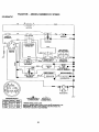
tractor to run poody, stop running, or prevent it from starting.
• Check wiring. See electrical wiring diagram in the Repair Parts section of this
manual.
TO REPLACE FUSE
Replace with 30 amp automotive-type plugin fuse. The fuse0holder is located behind
the dash.
TO REMOVE HOOD AND GRILL ASSEMBLY
• Raise hood.
Unsnap headlight wire connector.
•" Stand m front of tractor. Grasp hood at
sides, tilt toward engine and lift off of
tractor.
• To replace, reverse above procedures.
REPLACING BA'n'ERY
ACAUTION:
Do not short battery terminals by allowing a wrench or any other
object to contact both terminals at the
same time. Before connecting battery,
remove metal bracelets, wristwatcn
bands rings etc.
Positive term na must be connected first to
prevent sparking from accidental groundmg.
• Lift hood to raised position.
• Remove terminal guard.
• Disconnect BLACK battery cable then
RED battery cable and carefully remove
battery from tractor,
• Install new battery with terminals in same
position as old batte_.
Hood
•
Headlight
[
j
..."
Access Door_
:
_°°
(Red) Cable
Terminal
Guard
Wire
Connector
ENGINE
Maintenance, repair, or replacement of the
emission control devices and systems,
which are being done at the customers
expense_ may be performed by any nonroad engine repair establishment
or individual. Warranty repairs must be performed by
an authodzed engine manufacturer's
service outlet.
TO ADJUST THROTTLE
CONTROL
CABLE
The throttle control has been preset at the
factory and adjustment should not be necessary. Check adjustment as described
below before loosening cable. If adjustment is necessary, proceed as follows:
'o With engine not running, move throttle
control lever to fast position.
• Check that swivel is against side of quarter circle: If it is not, loosen cable clamp
screw and pull cable back until swivel is
against quarter circle. Tighten cable
clamp screw securely.
TO ADJUST CHOKE CONTROL
The choke control has been preset at the
factory and adjustment should not be necessary. Check adjustment as descdbed
below before loosening cable. If adjustment is necessary, proceed as follows:
First connect RED battery cable to positive (+) battery terminal with hex bolt and
:Reinstall
keps nut terminal
as shown.guard.
Tighten •securely.
Connect BLACK groundin_ cable to negative (-) battery terminal with remaining
hex bolt and keps nut. Tighten
securely.
,
• Close terminal access doors.
• Close hood.
Hex Bolt
Keps
Terminal
%
Cable
TO REPLACE HEADLIGHT
BULB
• Raise hood.
• Pull bulb holder out of the hole in the
backside of the grill.
25
TO ADJUST CHOKE CONTROL
The choke control has been preset at the
factory and adjustment should not be necessary. Check adjustment as described
below before loosening cable. If adjustment is necessary, proceed as follows:
• With engine not running, move choke
control (located on dash panel) to full
choke position.
• Remove air cleaner cover, filter and cartridge plate to expose carburetor choke
(see "AIR FILTER" in the Customer
Responsibilities section of this manual).
• Choke should be closed. If it is not,
loosen casing clamp screw and move
choke cable until choke is completely
closed. Tighten casing clamp screw securely.
• Reassemble air cleaner.
Clamp Screw-_-_
Quarter
Circle_
L_
• With engine off turn idle mixture screw
in (clockwise) closing it finger tight and
then turn out (counterclockwise) 1-1/4
to 1-1/2 rums.
FINAL SE'I-I'ING • Start engine and allow to warm for five
minutes. Make final adjustments with
engine running and shift/motion control
lever in neutral (N) position.
• With throttle control lever in slow position, hold throttle lever against idle
speed screw and adjust idle speed
screw to obtain 1200 to 1400 RPM.
• While still holding throttle lever against
idle speed screw, turn idle mixture
screw in (clockwise) until engine begins
to die and then turn out (counterclockwise) until en_]ine runs rough. Tum
screw to a point midway between those
• two positions.
• Continue to hold throttle lever against
idle speed screw and adjust idle speed
screw to obtain 900 to 1200 RPM. Release throttle lever.
ACCELERATION
TEST • Move throttle control lever from slow to
fast position. If engine hesitates or dies,
turn idle mixture screw out (counterclockwise) 118 turn. Repeat test and
continue to adjust, if necessary, until
engine accelerates smoothly.
High speed stop is factory adjusted. Do
not adjust - damage may result.
IMPORTANT:
Never tamper with the
engine governor, which Is factory set for
proper engine speed. Overspeeding the
engine above the factory high speed setting can be dangerous. If you think the
engine-governed high speed needs
adjusting, contact your nearest authorized
service center/department,
which has
proper equipment and experience to make
any necessary adjustments.
I
_/
Chok
Lever
TO ADJUST CARBURETOR
The carburetor has been preset at the factory and adjustment should not be necessary. However, minor adjustment may be
required to compensate for differences in
fuel, temperature, altitude or load. if the
carburetor does need adjustment, proceed
as follows:
In general, turning the mixture screw in
(clockwise) decreases the supply of fuel to
the engine giving a leaner fuel/air mixture.
Turniny the mixture screw out (counterclockw=se) increases the supply of fuel to
the engine giving a richer fuel/air mixture.
IMPORTANT:
Damage to the needles and
the seats in carburetor may result if screw
is turned in too tight.
PRELIMINARY
SETTING -
Idle Mixture Screw
Throttle Lever
_
dle Speed
Screw
Idle Mixture
• Be sure you have a clean air filter, and
the throttle control cable and choke are
adjusted properly (see above).
Screw
Throttle Lever
26
Immediately prepare your tractor for storage at the end of the season or if the tractor will not be used for 30 days or more.
A_,CAUTION:
Never store the tractor with
gasoline in the tank inside a building
where fumes may reach an open flame or
spark. Allow the engine to cool before
storing in any enclosure.
TRACTOR
Remove mower from tractor for winter
storage. This will allow you to clean it thoroughly. Remove all dirt, grease, leaves,
etc. Store in a clean, dry area.
• Clean entire tractor (See CLEANING"
in the Maintenance section of this manual).
• Inspect and replace belts, if necessary
(See belt replacement instructions in the
Service and Adjustments
section of this
manual).
• Lubricate as shown in the Maintenance
section of this manual.
• Be sure that all nuts, bolts and screws
are securely fastened. Inspect moving
parts for damage, breakage and wear.
Replace if necessary.
• Touch up all rusted or chipped paint surfaces; sand lightly before painting.
BATTERY
• Fully charge the battery for storage.
• After a period of time in storage, battery
may require recharging.
• To help prevent corrosion and power
leakage during long period_ of storage,
battery cables should be disconnected
and battery cleaned thoroughly (see
"TO CLEAN BATTERY AND TERMINALS" in the Maintenance section of
this manual).
• After cleaning, leave cables disconnected and place cables where they cannot
come in contact with battery terminals.
• If battery is removed from tractor for
storage, do not store battery directly on
concrete or damp surfaces.
ENGINE
FUEL SYSTEM
IMPORTANT:
It is important to prevent
_uUmdeposits from forming in essential
el system parts such as carburetor, fuel
filter, fuel hose, or tank during storage.
Also, experience indicates that alcohol
blended fuels (called gasohol or using
ethanol or methanol) can attract moisture
which leads to separation and formation of
acids during storage. Acidic gas can damage the fuel system of an engine while in
storage.
• Drain the fuel tank.
• Start the engine and let it run until the
fuel lines and carburetor are empty.
• Never use engine or carburetor cleaner
products in the fuel tank or permanent
damage may occur.
• Use fresh fuel next season.
NOTE: Fuel stabilizer is an acceptable
alternative in minimizing the formation of
fuel gum deposits during storage. Add stabilizer to gasoline in fuel tank or storage
container. Always follow the mix ratio
found on stabilizer container. Run engine
at least 10 minutes after adding stabilizer
to allow the stabilizer to reach the carburetor. Do not drain the gas tank and carburetor if using fuel stabilizer.
ENGINE OIL
Drain oil (with engine warm) and replace
with clean engine oil. (See "ENGINE" in
the Maintenance
section of this manual).
CYLINDER(S)
• Remove spark plug(s).
Pour one ounce of oil through spark
plug hole(s) into cylinder(s).
• Turn ignition key to "START" position for
a few seconds to distribute oil.
• Replace with new spark plug(s).
OTHER
• Do not store gasoline from one season
to another.
• Replace your gasoline can if it starts to
rust. Rust and/or dirt in your gasoline
• will cause problems.
• If possible, store your tractor indoors
and cover it to give protection from dust
and dirt. •
• Cover your tractor with a suitable protective cover that does not retain moisture. Do not use plastic. Plastic cannot
breathe, which allows condensation to
form and cause your tractor to rust.
IMPORTANT:
Never cover tractor while
engine and exhaust areas are still warm.
27
TROUBLESHOOTING
PROBLEM
Will not start
CHART
CAUSE
CORRECTION
Out of fuel.
• Fill fuel tank.
Engine not "CHOKED" properly. I" See "TO START ENGINE" in
Operation section.
• Wait several minutes before
Engine flooded.
attempting to start.
: Replace spark plug.
Clean/replace air filter.
!• Replace fuel filter.
• Drain fuel tank and carburetor,
refill tank with fresh
gasoline and replace fuel filter.
• Bad spark plug.
Dirty air filter.
• Dirty fuel filter.
• Water in fuel.
: Loose or damaged wiring.
Carburetor out of adjustment.
Engine valves out of adjustment.
Herd to start
• Dirty air filter.
: Bad spark plug.
Weak or dead battery.
: Dirty fuel filter.
Stale or dirty fuel.
: Loose or damaged wiring,
Carburetor out of adjustment.
Engine valves out of adjustment.
Engine will not turn
over
Engine clicks but will
not start
Loss of power
See "Toall
Adjust
Carburetor" in
I: Check
wiring.
Service and Adjustn_ants
section,
• Contact an authodzed se_ce
center.
• Clutch/brake pedal not
depressed.
• Attachment clutch is engaged.
• Weak or dead battery.
• Blown fuse.
Corroded battery terminals.
i Loose or damaged widng.
Faulty ignitionswitch.
• Faulty solenoid or starter.
• Faulty operator presence
switchIes}.
• Weak or dead battery,
• Corroded battery terminals.
• Loose or damaged wiring.
• Faulty solenoid or starter.
Cutting too much grass/too fast.
Throttle in "CHOKE" position.
Build-up of grass, leaves and
trash under mower.
• Dirty air filter.
Low oil level/dirty oil.
• Faulty spark plug.
• Dirty fuel filter.
• Stale or dirty fuel.
• Water in fuel.
• Spark plug wire loose.
• Dirty engine air screen/fins.
28
Replace spark plug.
Clean/replace
air filter.battery.
Recharge or replace
Replace fuel filter.
• Drain fuel tank and refill with
fresh gasoline.
: Check all widng.
See "To Adjust Carburetor" in
Service and Adjustments
section.
• Contact an authodzed service
center.
• Depress clutch/brake pedal.
• Disengage attachment clutch.
• Recharge or replace battery.
Replace fuse.,
• Clean battery terminals.
Check all widng.
• Check/replace ignitionswitch.
Check/replace solenoid or
starter.
• Contact an authorized service
center.
• Recharge or replace battery.
• Clean battery terminals.
• Check all widng.
Check/replace solenoid or
starter.
•
•
•
•
Set in "Higher Cut" positionireduce speed.
Adjust throttle control.
Clean underside of mower housing.
• Clean/replace air filter.
• Check oil level/change oil.
• Clean and regap or change spark
plutj.
• Replace fuel filter.
• Drain fuel tank and refill with
fresh gasoline.
• Drainfuel tank and carburetor,
refill tank with fresh gasoline and
replace fuel filter.
• Connect and tighten spark plug
wire.
• Clean engine air screenlfins.
TROUBLESHOOTING
PROBLEM
CHART
CORRECTION
CAUSE
Loss of power (cant'd) • Dirty/clogged muffler.
Loose
or damaged
wiring.
Carburetor
out of adjustment.
• Engine valves out of adjustment.
Excessive vibration
• Clean/replace muffler.
• Check all widng.
See "To Adjust Carburetor" in
Service and Adjustments
section.
• Contact an authorized service
center.
Worn, bent or loose blade.
Bent blade mandrel.
• Loose/damaged part(s).
• Replace blade. Tighten blade bolt.
Engine continues to
run when operator
leaves seat with attachment clutch
engaged
Poor cut - uneven
• Faulty operator-safety presence
control system.
• Check v_,idng,switches and connections. If not
corrected, contact an authorized
service center/department.
• Worn, bent or loose blade.
• Mower deck not level.
• Buildup of grass, leaves, and
trash under mower.
• Bent blade mandrel.
• Clogged mower deck vent holes
from buildup of
grass, leaves, and trash around
mandrels.
• Replace blade. Tighten blade bolt.
Level mower deck.
• Clean underside of mower housing.
• Replace blade mandrel.
• Clean around mandrels to open
vent holes.
Mower blades will not
rotate
• Obstruction in clutch mechanism.
• Worn/damaged mower drive
belt.
• Frozen idler pulley.
• Frozen blade mandrel.
• Remove obstruction.
• Engine speed too slow.
•
•
•
•
Travel speed too fast.
Wet grass.
Mower,deck not level.
Low/uneven tire air pressure.
Headlight(s) not work
ing (if so equipped)
•
•
•
•
•
Switch is "OFF'.
Bulb(s) burned out.
Faulty light switch.
Loose or damaged wiring.
Blown fuse.
Battery will not charge
• Bad battery cell(s).
• Poor cable connections.
• Faulty regulator (if so
equipped).
• Faulty alternator.
Poor grass discharge
Replace blade mandrel.
Tighten loose part(s). Replace
damaged parts.
• Replace mower ddve bell
• Replace idler pulley.
• Replace blade mandrel.
• Place throttte control in "FAST"
position.
• Shift to slower speed.
• Allow grass to dry before mowing.
Level mower deck.
• Check tiros for proper air pressure.
• Worn, bent or loose blade.
• Replaceisharpan blade. Tighten
blade bolt.
• Clean underside of mower hous• Buildup of grass, leaves and
trash under mower.
ing.
• Mower ddve belt worn.
• Replace mower ddve belt.
• Reinstall blades sharp edge
• Blades improperly installed.
down.
Improper blades used.
• Replace with blades listed in this
manual.
Clogged mower deck vent holes • Clean around mandrels to open
vent holes.
frombuildup of
grass, leaves, and trash around
mandrels.
29
•Tum
switch "ON".
FJeplacebulb(s).
Check/replace light switch.
• Check wiringand connections.
• Replace fuse.
Replace
battery.
Check/clean
all connections.
• Replace regulator.
• Replace alternator.
TROUBLESHOOTING
CHART
PROBLEM
CAUSE
CORRECTION
Loss of drive
• Freewheel control in =disengaged" position.
• Motion drive belt worn, damaged or broken.
• Airtrapped in transmission during shipment
or servicing.
• Place freewheel control in
"engaged" position.
* Replace motion drive belt.
° Engine throttle control not set
at "SLOW" position for 30 seconds before stopping engine,
° Move throttle control to "SLOW"
position and allow to idle for 30
seconds before stopping engine.
Engine =backfires"
when turning engine
"OFF"
• Purge transmission.
t
30
TRACTOR
- - MODEL
NUMBER
917.270823
SCHEMATIC
L
BAI-I_RY
(OPTIONAL)
m.UE
-q
IGNITION
UNIT
A
•IF
_
_2
l_tiN
LINE =
SPARK
PLUG
C-_P
PLUGS ON
CYL ENGINES)
I
!
J
FUEL S._JT-OFF
SOLENOID
HEADLIGHTS
IGNITION SWITCH
•
O
NON-REMOVABLE
REMOVABLE
WIRING INSULATED CUPS
e
NOTE: IF WIRING INSULATED CLIPS WERE REMOVED FOR
CONNECTIONS
CONNECTIONS
SERVICING OF UNIT, THEY SHOULD BE REPLACED TO
PROPERLY SECURE YOUR WIRING.
31
/-7
TRACTOR
- - MODEL
NUMBER
ELECTRICAL
41
25
32
917.270823
TRACTOR
- - MODEL
NUMBER
917.270823
ELECTRICAL
KEY
PART
NO.
NO.
DESCRIPTION
16,3465
74760412
7603J
145211
150109
145769
153664
STD551125
73350400
166182
4152J
4799J
146148
166180
73510400
145491
121305X
140301
124211X
141226
109310X
166145
71110408
131563
145673
73640400
122822X
141940
17490508
166660
Battery
Bolt, Hex 1/4-20 x 3/4
Tray, Batte_
Bait, Btr Front 1/4-20 x 7-1/2
Hoiddown Battery Front Mount
Nut, Push Nyk:_ Battery Front 1/4
Switch InterlockPush-In
Washer, Lock 1/4
NUt,Hex, Jam 1/4.20
Harness. Ught Socket (w/4152J)
Light Bulb
Cable. Battery
Cable, Battery
Fuse
Nut Kepo Hex 1/4-20 Unc
Cable, Ground
Switch, Seat
Switch, Ignition 4 Position
Nut, Ignition
Cover, IgnitionSwitch
Key, Molded, Craftsman
Harness, Ignition
BoltBlkFinHex 1/4-20UNCx1/2
Cover, Terminat
Solenoid
Nut Keps BIkHex 114-20 UNC
Ammeter Rectangular 15 Amp
ProtectionWire Loop (Hour Meter)
ScrewThdrol 5/16-18 x 1/2
HarneSSEngine
1
2
8
10
11
12
16
19
20
21
22
24
25
26
27
28
29
30
31
32
33
40
41
42
43
44
45
52
55
70
NOTE: Allcomponent dimensionsgiven in U.S. inches
1 inch= 25.4 mm
33
TRACTOR
- - MODEL
NUMBER
917.270823
CHASSIS AND ENCLOSURES
28
12
58
53
31
55
37
23
54
6O
• 1145
14
34
TRACTOR
- - MODEL
NUMBER
917.270823
CHASSIS AND ENCLOSURES
KEY
PART
NO.
NO.
1
2
3
4
5
9
10
11
12
13
14
17
18
20
23
25
26
28
29
30
31
37
38
39
51
52
53
54
55
57
58
60
64
74
140
142
143
144
145
166819
140356
17490612
19131216
155272
161917X013
STD533710
155927
145660
169118
17490608
144983X558
126938X
156437
124628X
19131312
STD541437
156725X558
155217X599
151287X558
139976
17490508
139886
139887
73800400
19091416
145201
161464
14_o02
74780412
150127
STD533707
154798
STD541437
158418
165867
154966
154207
156524
DESCRIPTION
Chassis
Drawhar
Screw,Thd., Roll. 3/8-16 x 3/4 Type 3-1"
Washer 13/32 x 3/4 x 16 Ga. t
BumperHood Dash
Dash
Boll Cardage 3/8-16 x 1
Panel, Dash, LH
Clip _nnerman Grille P/L
Panel, Dash, RH
Screw Thdrol 3/8-16 x 1/2
HoodAssembly
BumperHood
Plate Battery/FuelTank Fr
BushingSnap Nyl BIk Fuel Une
Washer 13/32 x 13/16 x 12 Gauge
Locknut,Hex, wi_ Insert 3/8-16 UNC
Grille. MS-558
Lens, Gdlla
Fender/Footrest
Bracket, Fender/Support
Screw,ThdroL 5/16-18 x 1/2TYT
PivotBracketAssembly,LH, Mower, Rear
PivotBracketAssembly, RH, Mower, Rear
Nut Lockw/lnsert 1/4-20 Unc
Washer 9/32 x 7/8 x 16 Ga.
BracketGrine PickolfLh
Screw Hex Wshd 8-18 x7/8
BracketGdlle PickoffRh
Bolt Fin Hex 1/4-20 x .75 Unc
Air Duct PL/LT Engine
Bolt Rdhd Sqnk 3/8-16 UNC x 3/4
Dash Lower STLT
NutCrownlock3/8-16 UNC
BracketSuspensionFront
Plate Reinforcement STLT
BracketSwaybar Chassis
BracketFootrest STLT
Rod PivotChassiS/Hood
NOTE: Allcomponent dimensionsgiven in U.S. inches
1 inch = 25.4 mm
35
"_ _c'_O_ . . _0 0_'%"
_._
9YI. _-7_)_3
G_OUt_o t)_W_
36
TRACTOR
- - MODEL
NUMBER
917.270823
GROUND DRIVE
KEY
NO.
1
PART
NO.
......
2
3
8
10
14
16
142431
143995
165866
STD561210
10040400
STD541431
18
STD523710
19
STD541437
21
22
24
25
26
27
28
29
30
32
34
35
36
37
38
39
40
41
42
130564
145627
73350600
106888X
STD551037
STD561210
145204
124236X
130807
74760512
155071
120183X
19211616
1572H
131494
STD523727
4470J
165838
19131312
47
48
49
50
51
52
53
55
56
57
59
61
127783
154407
123205X
STD523715
STD541437
STD541431
105710X
105709X
STD523712
140294
140312
17490612
62
63
64
65
66
70
8883R
140186
71170764
STD551143
154778
134683
KEY
NO.
DESCRIPTION
Transaxle(See Breakdown)
Hydro Gr 319-0650
Spdng, Return, Brake
Pulley,Transaxle
RodShiftFeoderAdjust
PinCotter 1/8x 1 CAD
Washer Lock Hvy Helical
NutLockHexW!lns. 5/16-18
Unc
BoltFin Hex 3/8-16 Unc x 1
Gr. 5
NutLockHexW/Wsh 3/8-16
Unc
Knob, Deluxe 1/2-13
Rod, Brake Hydro
Nut, Hex Jam 3/8-16 Unc
Spring,Brake Rod
Washer
PinCotter I/8x3,/4CAD.
Rod, ParkingBrake
Cap, ParkingBrake
Bracket,Transaxla
BoltHex Hd 5/16-18 Unc x 3/4
Shaft, FootPedal
Bearing, Nylon
Washer
Pin, Roll
Pulley,Idler, Rat
Bolt
Spacer, Split
Keeper, Bolt Idler
Washer 13/32 x 13/16 x 12
Gauge
Pulley,Idler, V-Groove
BeUcrankClutch Grad Dry STL
Retainer,Bolt
Bolt
NutCrownlock 3/8-16UNC
Nut, Crownlock 5/16.18 Unc
Link,Clutch
Spdng, Retum, Clutch
Bolt Hex 3/8-16x 1-1/4
V-Belt,Ground Drive
Keeper, Center Span
ScrewThdrol. 3:/6.16x3/4Ty.
TI"
Cover, Pedal
Pulley,Engine
Bolt Hex 7/16.20 x 4 Gr. 5
Washer
Keeper Belt EngineHydro
Guide Belt RH Engine
PART
NO.
71
72
73
74
75
140158
19132012
156347
121199X
121749X
76
77
78
STD581075
123583X
121748X
81
165591
82
83
84
89
90
93
94
95
96
97
165711
19171216
165815
164890X428
124346X
142564
140462
167696
4497H
140469
98
102
73510600
141322
103
73940800
104
105
116
145
146
147
150
151
156
157
158
159
160
161
140156
71070516
72110610
74490540
74490536
74490524
165850
19133210
166002
153236
165589
165494
19292016
72140406
162
163
73680400
74780416
DESCRIPTION
Strap Torque Lh Hydro 18/20"T
Washer 13/32 x 1-1/4 x 12 Ga.
Strap Torque Rh Hydro 0650
Spacer, Split
Washer 25/32 x 1-1/4 x 16
G_luge
E-Ring
Key, Square
Washer 25/32 x 1-5/8 x 16
Gauge
Shalt Asm Cross Tapered 650
20
SpringTorsion
Washer 17/32 x 3/4 x 16 Ga.
LinkTraneaxle 0650 LT/YT/STL
Console, Shift
Nut Selt-Thd Wsh-hd 1/4 Zinc
Line Fuel Hydro 4"
Fan, Hydro 7*
Control Bypass Hydro
Retainer Spring 1• Zinc/Cad
Keeper Bolt Rh Hydro 0750.
18/20"
Nut Keps Hex 3/8-16 Unc
Washer BetTville.501D x
1.50D
Nut Hex Jam Toplook 1/4-20
Unf
Arm, Control Hydro
Screw Cap Hex 5/16 x 18 x 1
BoltCarr. 3/8-16 x 1.25
BoltHex Fk:jhd 5/16-18 Gr. 5
Belt Hex Flghd 5/16-18 x 2-1/4
BoltHex RcJhd5/16-18 x 1-1/2
Bushing BellcrankGrd Drive
Washer 13/32 x 2 x 10 Ga.
Washer Srrtod 5/161D x 1.125
BoltShoulder 5/16-18 Unc - 2A
BracketShift Mount
Hub Tappered Flange ShiftLt
Washer 29/32 x 1-1/4 x 16 Ga
Bolt Rdhd Sqnk 1/4-20 x 3/4 Gr
5
Nut Crownlockl/4-20 Unc
Bolt Hex Fin 1/4-20 Uric x 1 Gr
5
Washer 5/8 x .281 x 10 Ga
BracketPivot Lever
Screw 5/16-18 x 5/8
Bolt Shoulder5/16-18 x .561
Plate Fastening Lt
164 19091010
165 165623
166 166880
•
168 165492
169 165580
NOTE: All componentdimensionsgiven in U.S. inches
I inch= 25.4 mm
37
TRACTOR
- - MODEL
NUMBER
STEERING ASSEMBLY
f--
.-%"-'_-11
r
......
._.__._j
i
i
2S
\
38
917.270823
TRACTOR
- - MODEL
NUMBER
917.270823
STEERING ASSEMBLY
KEY
NO.
1
2
3
4
5
6
7
8
9
10
11
13
15
17
18
19
22
23
25
26
27
28
29
30
32
36
37
38
39
40
41
42
43
44
46
47
51
54
62
63
65
66
67
68
79
80
PART
NO.
139768
154427
156483
157473
6266H
121748X
19272016
12000029
3366R
156438
STD551137
154779
73901000
156546
57079
160395
165857
165851
154406
126847X
136874
19131416
17490612
STD561210
130465
155099
152927
139769
19133812
STD541537
100711L
145054
121749X
153720
121232X
6855M
73800500
74780520
167902
74780616
154780
154404
74781044
154429
19132012
74950612
DESCRIPTION
Steering Wheel
FrontAxle Assembly
SpindleAssembly, L.H.
SpindleAssembly, R.H.
Bearing, Race, Thrust, Hardened
Washer 25/32 x 1-5/8 x 16 Gauge
Washer 27/32 x 1-1/4 x 16 Gauge
Ring, Knp
Beedng, Steering Column
Link,Drag
Washer, Lock
Spacer, Beadng, Front Axle
Nut, Lock, Flange 5/8-11 UNC
Shaft Assembly,Steering
Washer, Thrust .515 x .750 x .033
Support,Shaft
Screw hex Wshhd Torx
PittmanShaft Assembly
Bracket,Steering
Bushing,Link,Drag
Gear, Sector
Washer 13/32 x 7/8 x 16 Gauge
Screw,Thd., Roll. 3/8-16 x 3/4
Pin
Rod, Tie
Bushing,Steering
Screw _ #10-32 x 5 x 3/8 Flange
Insert, Steering Wheel
Washer 13/32 x 2-3/8 x 12 Gauge
, Gripco Nut
Adaptor,Steering Wheel
Boot, Steering Dash P/L Mtl BIk
Washer 25/32 x 1-1/4 x 16 Gauge
ExtensionSteering Non-Adjust
Cap, Spindle
FitlJng,Grease
Nut Lock Hx W/Ins 5/16-18 UNC
Bolt Fin Hex 5/16-18 UNC x 1-1/4
Kit, Steering Assembly,Service
Bolt Fin Hex 3/6-16 uric. x I Gr. 5
Spacer AXle
BearingArm Pittman
Bolt Fin Hex 5/8-1luoc x 2-3/4
BraceAxle
Washer 13/32 x 1-1/4 x 12 Ga
Bolt Hex Nylon3/8-16 x 3/4
NOTE: Allcomponent dimensionsgiven in U.S. inches
1 inch= 25.4 mm
39
TRACTOR
- - MODEL
NUMBER
ENGINE
3_
_ ___3433
29
OPTIONAL
EQUIPMENT
Spark Arrester
4O
917.270823
TRACTOR - - MODEL NUMBER 917.270823
ENGINE
KEY
NO.
1
2
3
4
5
6
7
8
10
11
PART
NO,
162153
17720410
149723
122434X
122435X
138129
150176
145552
.......
12
13
14
15
16
23
25
26
29
31
32
33
34
35
37
38
39
78
81
13280336
13200300
STD551237
159880
145996
73920600
137180
157103
161696
123487X
106082X
17490512
8543R
109227X
17490620
128861
DESCRIPTION
ControlThrot Paddle 36 00
Screw Hex Thd Cut 1/4-20x5/8 T
Engine (See Breakdown) BriggsModel No. 350777-1034-A1
Muffler Exhaust
ExhaustAsm, Left
Exhaust Asm. Right
Clamp Tube Double Engine
Bolt 5/16 - 18 UNC X 3/4 W/Sems
Heat Shield Lt
Washer Lock Hvy. Helical 1/4
(Order From Engine Manufacturer)
Bolt Fin Hex 1/4-20 x 3/4
(Order From Engine Manufacturer)
Gasket Muffler
(Order From Engine Manufacturer)
NipplePipe 4-1/2"
ElbowStd 90 Degree 3/8-18 Npt
Washer Lock Ext Tooth3/8
Shield Browning/DebrisGuard
ControlChoke
Nut Keps 3/8-24 Unf
ArrestorSpark
Tank Fuel 3 50 Rear
Cap Fuel Guage STLT .
Clamp Hose Blk
Spacer Pad
Screw Thdrol 5/16-18 x 3/4 TYT
Line Fuel
PlugOil Drain (Order From EngineManufacturer)
Pad idler 1.75 x .75 x .06
ScrewThdrol 3/8-16x1-1/4 Tytt
Nut, Flange 1/4-20 StarterNut
NOTE: Allcomponent dimensionsgiven in U.S. inches
1 inch = 25.4 mm
41
TRACTOR
- - MODEL
NUMBER
917.270823
SEAT ASSEMBLY
KEY
NO.
1
2
3
4
5
6
7
8
9
lO
11
PART
NO.
DESCRIPTION
140123
140551
74760616
19131610
145OO6
STD541437
124181X
17490616
19131614
155925
166369
Seat 3450 BIIdblk Craftsman
Bracket Pnt PivotSeat (blk)
Bolt Fin Hex 3/8-16unc X 1
Washer 13/32,X 3/4 X 10 Ga
Clip Push In Hinged
Nut Hex Lock w/Ins 3/8-16 Unc
Spdng Seat Cprsn 2 250 BIk Zi
ScrewThdrol 3/8-16 X 1 Ty-tt
Washer 13/32 X 1X 14 Ga
Pan Pnt Seat (blk)
Knob Seat
KEY
NO.
PART
NQ,
DESCRIPTION
BracketPnt Mounting Switch
12 121246X
BushingSnap BIkNy150 Id
13
121248X
BoltRdhd Snt Nk 1/4-20xl-1/2
14 72050412
"15 134300
Spacer Split28 X 86 Zinc
SpdngCprsn 1 27 BIkPnt
16
121250X
NutLock 1/4 Lge Rg Gr 5 Z3nc
17
123976X
Bolt Shoulder 5/16-18 Unc-2A
21
153236 •
Nut Hex Lockw/Ins 5/16-18
22
STD541431
Washer 17/32 X 1-3/16 X 12 Ga.
24
19171912
BoltShoulder5/16-18 X 62
25
127018X
NOTE: All component dimensions given in U.S. inchesl inch = 25.4 mm
42
TRACTOR
- - MODEL
NUMBER
917.270823
DECALS
1
6
4
11
2
2O
14
14
13
KEY
NO.
PART
NO.
1
156439
2
3
4
5
163205
163200
163202
160876
6
133644
8
160879
9
10
11
163204
160880
156811
WHEELS
KEY
NO.
DESCRIPTION
Decal Fender Danger Sears
Decal Fend Auto Sears Gold
Decal Hood Rh Craftsman
Decal Hood Lh Craftsman
Decal HP Engine
Decal Maint Customer
Sears Dem
Decal Engine Radius
Decal Fender Craftsman Gold
Decal EngineAirCleanerCover
Decal Fender STLTL-IOper
lest E/S
13
14
15
19
20
22
---..
---
& TIRES
KEY
NO.
PART
NO.
DESCRIPTION
146046
163259
160396
138047
166887
149516
138311
169210
154515
154516
169463
169464
Decal V-belt Dr Sch Tractor E
Decal Dash Panel
Decal Mower Drive Schematic
Decal, BatteryDiehard Sears
Decal Deck Mower EZ3
Decal Battery
Decal LiftHandle
Decal, B_/-PassLt Hydro
Pad FootrestLh STLT
Pad FootrestRh STLT
Manual, Owner's (English)
Manual, Owner's (Spanish)
PART
NO,
DESCRIPTION
1
2
3
4
59192
65139
106222X
5990_
5.
6
106732X427
278H
7
9040H
4,10
11
8
9
10
•
106108X427
122082X
7152J
11
--
104757X
144334
Valve Cap, Tire
Stem, Valve
Tira, Front
Tube, Front1"ira
(Not Provided,Service Item
Only)
Rim, Front
Fitting,Grease (Front Wheel
Only)
Searing, Flange (Front Wheel
Only)
Rim, Rear
Tire, Rear
Tube, RearTire
(Not Provided,Service Item
Only)
Cap, Axle
Sealant, Tire (10 oz. Tube)
NOTE: All component dimensionsgiven in U.S. inches
1 inch = 25.4 mm
43
TRACTOR
- - MODEL
NUMBER
917.270823
LIFT ASSEMBLY
27
25 24
23
7
..8
/
/
/
/
49
/
/
30
3
\
13
4
6
6
5
13
19
13
20
19
44
•
.._%'J
1718
20
TRACTOR
- - MODEL
NUMBER
917.270823
LIFT ASSEMBLY
KEY
NO.
1
2
3
4
5
6
7
8
11
12
13
15
16
17
18
19
20
23
24
25
26
27
28
29
30
31
32
49
50
PART
NO.
DESCRIPTION
159460
159471
105767X
12000002
19211621
120183X
125631X
122365X
139865
139866
STD624008
127218
73350800
130171
73680800
139868
163552
110807X
19131016
2876H
76020308
126971X
73350600
138057
150233
140302
73540600
145212
110452X
LiftLever Inner Wire Asm.
ShaftAsm. Lift
Pin Groove
E Ring
Washer21/32x1 x21 Ga.
Bearing Nylong
Grip Handle Fluted
Button Plunger Read
LinkAsm LiftLH.
LinkAsm LiftR.H.
Retainer Spnng
LinkFront
Nut Jam Hex 1/2-13 Unc
Trunnion BIkTinc
Nut Look W/Wsh 1/2.13 Uric
Arm SuspensionMower
Retainer Spring
Nut, Special
Washer 13/32 x 5/8 x 16 Ga.
Spring
Pin, Cotter 3/32 x 1/2
Rod, Adjust Life
Nut, Hex Jam 3/8-16 UNC
Knob, InfiniteHeightAdmustment
Trunnion, Inf. Height
Beadng, Pvt. Lift. Spherical
Nut Crownlock 3/8-24
Nut, Hex Flange Lock
Nut, Push Phos. & Oil
NOTE: All component dimensionsgiven in U.S. inches
1 inch= 25.4 mm
45
TRACTOR
- - MODEL
NUMBER
917.270823
MOWER DECK
17
_21
>21
21
22
3 24
25
\
119"
16
27
18
_,_..---11
10.----,
9_
46
TRACTOR
- - MODEL
NUMBER
917.270823
MOWER DECK
KEY
NO.
PART
NO.
1
2
3
164961
STD533107
138017
4
5
6
8
9
10
11
12
13
138440
STD624008
130832
850857
STD551137
140296
134149
129895
137645
14
15
16
17
18
19
20
21
22
23
24
25
26
27
28
29
30
31
32
33
34
35
36
37
40
41
43
44
45
46
48
49
50
51
52
53
54
128774
110485X
140329
72110610
72140505
132827
159770
STD541431
134753
131267
105304X
123713X
110452X
130968
19111016
131491
157722
129963
153535
137266
STD5337"17
133835
131494
19131316
STD541437
133551
140083
140088
STD624003
137729
133944
155066
131340
STD541410
139888
131845
133943
KEY
NO.
DESCRIPTION
Mower Housing
Bolt
BracketAssembly,SwayBar,
Front
BracketAssembly,SwayBar
RetainerSpring
Arm, Suspension,Rear
Bolt, Hex 3/8-24 x 1.25 Gr. 8
Washer, Lock
Washer, Hardened
Blade, Mulching
Beadng, Ball
Shaft Assembly,Mandrel, Vented
(Incl. Key Number 6)
Housing,Mandrel, Vented
Beating, Ball, Mandrel
Stripper,Vented Mower Deck
Bolt, Carriage 3/6-16 x 2-1/4
Bolt,Carriage 5/16-18 x 5/8
Bolt, Shoulder
Baffle, Vortex
Nut, Crownlock5/16-18 UNC
Stiffener Bracket
Bracket, Deflector
Cap, Sleeve
Spring,Torsion,Deflector
Nut, Push
Shield, Deflector
Washerlli32x5/8x16Ga.
Rod, Hinge
ScrewThdrolRollingWshHd
Washer, Spacer
Pulley, Mandrel
Nut, Toplock,Ranged
Bolt
Fastner, Christmas Tree
Pulley, Idler, Flat
Washer 13/32 x 13/16 x 16 Ca.
Nut, Crownlcck3/6-16UNC
Rod, Pivot, with Nibs
Rod, Clutch, Secondary, w/Nibs
Guard, Mandrel, L.H.
Retainer
Screw, Thd. Roll 1/4-20 x 5/8
Washer, Hardened
RollerAssembly, Cam Follower
Boit, Shoulder#10-24Grade5
Locknut
Bolt, Shoulder 5/16-18 UNC
Arm Assembly, Pad, Brake
Washer, Hardened
PART
NO.
55
56
58
59
67
68
71
72
73
74
75
76
77
78
79
80
81
82
83
84
85
92
101
102
103
104
105
106
111
112
113
114
115
116
117
118
119
121
128
129
130
131
132
141
--
155046
122052X
140086
141043
162113
144200
142427
131870
127847
121748X
12000029
128903
127845
160570
127498
153701
73350600
142028
120958X
156084
72140620
STD541437
136420
71161010
19061216
STD551110
160793
2029J
155197
155198
17490512
73510500
72110504
4898H
165746
73930600
19121414
143723
153390
19131312
STD523710
STD533710
191322_3
6266H
130794
.
--
164963
DESCRIPTION
Arm, Idler
Spacer, Retainer
Spdng,TorsionBrakes 42"
Guard, Tuv Idler (94)
KnobCustom Oval
V-Belt
Rod, Clutch, Primary,with Nihe
Spril_g,Return
Arm,Clutch, Secondary
Washer 25/32 x 1-5/8 x 16 Ca.
Ring, Klip
Bolt,Sheulder 3/6-16 UNC x 1.44
Keeper, Spnng
Arm,Clutch, Pdmarj
Bushing,Large, Brass
Spdng, Mower Clutch
Nut, Hex Jam 3/8-16 UNC
Trunnion Adj. 94
Washer Sintered
Keeper Belt Idler
Bo_tCarriage 3/6-16 x 2-1/2
Lockout, Hex w/Wsh 3/8-16 UNC
Cover Mulching42" Black
Screw Truss Hd Phil10-24 x5/8
Washer #10
Washer Lock
Latch Asm Bagger
Nut Weld
Bracket Gauge, Wheel LH
Bracket'Gauge, Wheel RH
Screw Thdrol 5/16-18 x 3/4
Nut, Hex Kaps 5/16-18 UNC
Bolt, Carriage 5/16 UNC x 1/2
Bolt, Shoulder
Wheel, Gauge
Nut, Crownlock 3/8-16
Washer 13/32 x 7/8 x 14 Ca.
Bracket
Washer Felt
Washer 13/32 x 13/16 x 12 Ca.
Bolt, Fin Hex 3/8-16 Unc x 1 Gr. 5
Bolt RdhdSqnk 3/6-16 UNC x 1
Washer 13/32 x 1-3/8 x 3 Ca.
Washer Thrust .75 x 1.230
MandrelAssembly (Includes Key
Numbers 8-10, 12-15, 31 and 32)
Mower Deck, Complete (Stddeck
- orderseparately mulcher plate
components key nos. 101-106)
NOTE: Allcomponent dimensionsgiven in U.S.inches
1 inch= 25.4 mm
47
TRACTOR
- - MODEL
NUMBER
917.270823
HYDRO GEAR TRANSAXLE - - MODEL NUMBER 319-0650
58
41
91
4
3
35
48
TRACTOR
- - MODEL
NUMBER
917.270823
HYDRO GEAR TRANSAXLE - - MODEL NUMBER 319-0650
KEY
NO.
1
2
3
4
5
6
7
8
9
13
14
15
17
18
19
23
24
25
26
27
28
29
30
34
35
36
37
38
39
40
41
PART
NO.
DESCRIPTION
142930
142931
142932
142928
142933
142934
142935
150771
142937
142938
142939
142940
142941
150772
150773
142944
142945
142946
150774
142948
142949
142950
150787
142951
142952
142953
142954
142955
150777
150778
142958
Housing, Lower
Assembly,Upper Housing
Seal, Lip
Ring, Wire Retaining
Ring, Retaining
Beadng, Shaft Ball
Bearing, Cradle
Beedng, Thrust 30 x 52 x 13
Swashplate,Variable
Block, CylinderAssembly
Arm, Trunnion
Seal, Lip
Guide, Slot
Shaft, Motor
Bearing, Thrust 42x68x16
Block, CylinderAssembly
Seal, Lip 10 x 25 x 7
Actuator, Bypass
Center SectionAssembly Kit
Seal, Lip 26 x 42 x 8
Ring, Retaining
Washer 26 x 35 x 1
Plate, Bypass
Oil Filter Element
Arm, Bypass
Ring, Retaining
Arm, Actuating
Pin, Actuating
Bolt 5/16-24 x I-3/4"
Locknut,Hex 5/16-24 UNJC
Brake RotoriStatorKit
KEY
NO.
43
44
52
53
56
58
59
62
63
64
68
69
83
85
88
89
90
91
92
93
113
114
119
134
135
139
140
PART
NO.
DESCRIPTION
142884
150829
142991
142961
142963
142964
142965
142966
142967
142920
142969
144610
142971
150806
142973
142974
142975
142976
142977
142978
142917
142918
142980
144607
144608
150775
150776
Washer 7/16 x 7/8 x .060
DifferentialAssembly
Washer 3/4 x 1.5 x .13
Se_d .75 x 125 x .250
Shaft, Input
Bolt 114-20x 1.38
Pin .50D x .43 ID x .750
Arm, Control
Puck, Dampener
Set Screw
Spring
Stud 5/16-24
JackshaftAssembly
Jackshaft
Screw, Cap
Washer 7/16 x 1 x 1/2
Sleeve Beadng
Seal, Wiper
Spring,Block
Washer, Block Thrust
Cap, VentAssembly
Fitting,O-Ring Assembly
Spacer
Nut, Castle 5/16-24
Pin, Cotter
Spdng, C_mpression
Nut, Hex 5/16-24
NOTE: All componentdimensionsgiven in U.S. inches
I inch= 25.4 mm
49
TRACTOR
- - MODEL
BRIGGS & STRATTON ENGINE-MODEL
NUMBER
917.270823
NUMBER 350777 TYPE NUMBER 1034-A1
5_A0
081
(SEEREPAIR_
MANUAL)
5O
TRACTOR
- - MODEL
BRIGGS & STRAI-rON ENGINE-MODEL
NUMBER
917.270823
NUMBER 350777 TYPE NUMBER 1034-A1
0
1091 1_
127A
947
918
51
TRACTOR
- - MODEL
BRIGGS & STRATTON ENGINE-MODEL
NUMBER
917.270823
NUMBER 350777 TYPE NUMBER 1034-A1
_332
U 668
189
363
1005
52
TRACTOR
- - MODEL
BRIGGS & STRATTON ENGINE-MODEL
NUMBER
917.270823
NUMBER 350777 TYPE NUMBER 1034-A1
Ilia
72Z
m
I1_
m
Q_
53
116
TRACTOR
BRIGGS
KEY
NO,
1
2
3
5.1
5.2
7
8
9
10
11
12
13
15
16
18
20
22
23
24
25
& STRATTON
PART
NO.
807787
805107
805101
807821
807822
805658
807795
805379
805751
805362
805112
805097
805048
807779
94196
807638
805049
805696
808132
805016
807888
807991
807992
807993
26
27
28
29
32
33
34
35
37
40
42
45
46
50
51
52
53
54
75
78
84
87
95
95A
98
104
105
108
116
807889
807994
807995
807996
805099
807886
807900
805395
805089
805090
805078
805506
805092
805161
262679
807542
805772
805700
805023
805669
805006
805007
805447
914889
805054
805561
94466
807705
805586
807706
805562
805058
- - MODEL
ENGINE-MODEL
NUMBER
NUMBER
917.270823
350777
KEY PART
NO. NO.
DESCRIPTION
CylinderAssembly
Bearing, Cylinder
*Seal, Oil
Head, Cylinder, Cylinder #1
Head, Cylinder, Cylinder #2
.... Gasket, Cylinder Head
BrsatherAssembly
*Gasket,Breather
Screw
Tube, Breather
*Gasket, Crankcase Cover
Screw, Cylinder Head
Plug, Oil Drain
Crankshaft
Key,'liming Gear Retaining
CoverAssembly, Crankcase
*Seal, Oil
Screw, Crankcase Cover
Flywheel, Magneto
Key, Flywheel
PistonAssembly,Standard Size
PistonAssembly,.010"
Oversize
PistonAssembly,.020"
Oversize
PistonAssembly,.030"
Oversize
Ring Set, Piston, Standard Size
Ring Set, Piston, .010" Oversize
Ring Set, Piston, .020"Oversize
Ring Set, Piston, .030"Oversize
Lock, Piston Pin
Pin Assembly,Piston, Standard
Rod Assembly,Connecting
Screw, Connecting Rod
Valve, Exhaust"
Valve, Intake
Spring, Valve
Cover, Starter
Retainer,Valve Spring
Retainer,Valve
Tappet, Valve
Gear, Cam
Manifold, Intake
*Gasket, Carburetor Mounting
.... Gasket, Intake Manifold
Stud, Carburetor Mounting
Screw, Sems
Washer, Spdng
Screw, Seres
Plug, Pipe
Seal, Governor Shaft
Screw, Valve Mounting
Screw, Valve Mounting
Screw, Throttle Adjustment
*'Pin, Float Hinge
**Fuel InletAssembly
Valve, Choke
*O-Ring, Oil Pump
116A
116B
117
118
121
122
125
127
127A
130
131
133
137
805198
224531
806109
808374
807708
805674
808372
805570
805571
808572
808375
807710
---
141
142
161
166
166A
167
171
187
807711
806110
807857
805343
805073
805420
805019
393815
296004
188
188A
189
192
94627
805247
805449
807623
201
805480
209
905462
209A 805453
216 805439
222 808195
227 807528
232 805465
240 493629
243 805964
254 907713
265 221535
271 808145
277 805018
304 808220
305 805406
307 805025
308.1 808309
308.2 808098
309 494990
310
94004
**
***
....
TYPE NUMBER
1034-A1
DESCRIPTION
*O-Ring, Crankcase Cover
**Washer, Bowl
**Jet, Main
**Valve, Idle Adjusting Needle
CarburetorOverhaul Kit
Spacer, Carburetor
CarburetorAssembly
Plug, Welch
t Plub, Welch
Valve, Throttle
Shaft, ThrottleAssembly
Float, Bowl
*'Gasket, Bowl (Sold in Kit
Only)
Shaft,Choke
**Nozzle, Carburetor
Base, Air Cleaner
Stud, RockerArm
Stud, Oil FilterAdapter
****Washer, Valve Cover
***Nut, Nylock
Hose, Fuel, 11"Long
Hose, Fuel, 23" Long
(Cut to Required Length)
Screw, Fan Retainer Mounting
Screw, Starter Mounting
Washer, Lock
Screw, Valve Adjustment
(Includes Jam Nut)
Link, Governor
Spring, Governor
Spdng, Governed Idle
Link, Choke
Bracket, Governor Control
Lever Assembly,Governor
Spring, Governor Link
Filter,Fuel
Screen, Oil
Drain, CarburetorBowl
Clamp, Casing
Bracket,Choke Control
Washer
Housing, Blower,Black
Screw, Sems
Screw, Sems
Cover, Air Guide, Cylinder #1
Cover, Air Guide, Cylinder #2
Motor, Starting
Bolt
Includedin Gasket Set (807887)
Included in Carburetor Overhaul Kit(807708)
Include,d in Valve Overhaul Kit (807910)
Inc!udodin both Gasket Set (807887),
and Valve Overhaul Kit (80791 O)
NOTE: All componentdimensionsgiven in U.S. inches
1 inch = 25.4 mm
54
TRACTOR
- - MODEL
BRIGGS & STRA'n'ON ENGINE-MODEL
PART
NO.
NUMBER
NUMBER 350777 TYPE NUMBER 1034-A1
KEY PART
NO. NO.
DESCRIPTION
324
332
333
334
337
351
353
353A
354
354A
356
358
363
387
423
445
467
474
501
510
513
520
523
524
525
526
527
535
537
544
552
552A
562
572
573
592
601
613
614
615
615A
616
634
634A
634B
634C
634D
635
494439
806028
492341
806104
491055
805169
94791
806101
90576
810078
493792
807887
19203
808322
805260
394018
491875
393295
394890
495878
398003
93722
807985
805011
807611
805448
223167
272490
805655
490309
805412
805413
805381
805197
807663
805383
93053
805158
806096
808578
808577
807596
805416
805580
805574
806079
805576
805529
Screen, Rotating
Nut, Hex
Armature, Magneto
Screw, Mounting
Plug, Spark
Screw. Hex Head
Washer, Lock
Washer, Lock
Nut, Hex
Nut, Hex
Wire, Ground
Gasket Set
Puller,Flywheel
Pump, Fuel
Screw, Sems
Cartridge, Air Cleaner
Knob, AirCleaner
Stator,Alternator
Regulator,Alternator
DdveAssembly
ClutchAssembly
Terminal, Spade
Dipstick
Seal, FltlerTube
Tube, Oil Filler
Screw, Regulator Mounting
Clamp, Fuel Pipe
Element, Foam
*Gasket, Air Cleaner
ArmatureAseembly
Bushing,Governor Shaft
Bushing,Govemor Shaft
Bolt
Baffle, Breather
Back Plate Assembly
Nut, Hex
Clamp, Hose
Screw, Sems
Pin, Cotter
** Retainer
** Retainer
Fork, Governor
Washer, Governor Shaft
**Shaft Seal Kit
** Collar, Throttle Shaft
SeaI, Throttle Shaft
** Washer, Plain
Elbow, Spark Plug
642
643
657
668
718
722
726
807862
805631
805009
805402
805103
805483
807805
Cover, Air Cleaner
Plate, Cartridge
Screw, Sems
Spacer, RotatingScreen
Dowel, Crankcase
*Seal, Breather Screw
Gear, Flywheel Ring
727
729
729A
729B
741
783
788
805505
805641
224356
280470
805675
280104
807685
Shield, Starter
Grommet
Clip, Debris
Clip, Wire
Gear, "lqming
Gear
Bracket,FtJelPump
917.270823
801
802
394856
494988
803
819
823
842
851
862
864
866
868
869
870
871
876
879
883
896
918
947
975
977
494205
805057
805317
270920
473880
807859
805083
805738
805094
805085
805086
805084
495877
805841
805024
94288
393815
808154
807913
807916
978
982
985
1004
1005
1006
1013
1014
1022
1023
805250
805030
398525
805632
808082
224413
805581
807963
806039
805100
807665
1024 807546
1025 805313
1026 805352
1026A 805617
1027 492932
1028 805292
1029 808096
1030 805342
1031 805341
1033 807910
1036 807688
1037 807217
1054" 280275
1054A 270723
DESCRIPTION
Cap Assembly, Drive End
Cap Assembly, Commutator
End
HousiegAssembly
Screw, Sems
Screw, Mounting
O-Ring
Telminal, IgnitionCable
Bracket,Air Cleaner
Liner, Exhaust Port
Valley Cover, Air Guide
Seal, Valve Guide
Seat, Intake Valve
Seat, Exhaust Valve
Guide, Valve
Retainer Kit
Cover, Carburetor
.... Gasket, Exhaust Manifold
Pin, Roll
Line, Vaccum
Solenoid
Bowl, FuelAsssembly
Gasket Set, Carburetor
(Consistsof Key Numbers 116B
and 137)
*Gasket, Oil FilterAdapter
Screw, Sems
InsulatorAssembly
Tube, Air Inlet
Fan, Rywheel
Retainer Fan
** Seal, Choke Shaft
Shield, Carburetor
.... Gasket, Valve Cover
Cover, Valve
Cover, Valve (Used on Cylinder
#1 on Fuel PumpApplications)
Oil Pump Assea'toly
Slider, Governor
Rod, Push(Intake)
Rod, Push (Exhaust)
Filter,Oil
Adapter, Oil Filter
Ann, Rocker
Shaft, RockerArm
Support, RockerArm
Overhaul Kit, Valve
Breather Gasket Set
**Ball, Choke Locator
"he,Cable
"13e,Cable
1058
1091
272104
Manual, Operator(_s
805858
•
Cap, Limlter
RPM Settings: Low Speed: 1200-1600
High Speed: 3200-3400
Includedin Gasket Set (807887)
** Included in CarburetorOverhaul Kit (807708)
*** Included in Valve Overhaul Kit (807910)
....
Included in both Gasket Set (807887),
and Valve Overhaul Kit (807910)
NOTE: Allcomponent dimensionsgiven in U.S. inches
1 inch= 25.4 mm
55
56
57
58
SUGGESTED
GUIDE FOR SIGHTING SLOPES FOR SAFE OPERATION
ONLY RIDE UP AND DOWN HILL,
NOT ACROSS HILL
Ol
€.O
I
Operate your Tractor up and down the face of slopes (not I
greater than 15°), never across the face. Make turns gradually to prevent tipping or loss of control. Exercise extreme
caution when changing direction on slopes.
For in-home major brand repair service:
Call 24 hours a day, 7 days a week
1-800-4- MY-H O M EsM(1-800-469-4663)
Para pedir servicio de reparaci6n a domicilio
1-800-676-5811
In Canada for all your service and parts needs call
Au Canada pour tout le service ou les pi_ces
1-800-665-4455
For the repair or replacement parts you need:
Call 6 am-11 pm CST, 7 days a week
PartsDirectS"
1-800-366-PART
(1-800-366-7278)
Para ordenar piezas con entrega a domicilio
1-800-659-7084
For the location of a Sears Parts and Repair Center
in your area:
Call 24 Hours a day, 7 days a week
• 1-800-488-1222
For information on purchasing a Sears Maintenance
Agreement or to inquire about an existing Agreement:
Call 9 am-5 pm, Monday - Saturday
1-800-827-6655
•
•
HomeCentralSM
169463
3.25.99
JH
Printed in U.S.A.