1
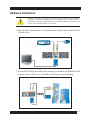
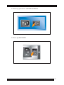
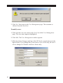
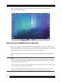
1
2
FCC Information
This is a FCC Class A product. In a domestic environment, this product may
cause radio interference in which case the user may be required to take adequate measures.
This equipment has been tested and found to comply with the limits for a
Class A digital device, pursuant to Part 15 of the FCC rules. These limits are
designed to provide reasonable protection against harmful interference when
the equipment is operated in a commercial environment. This equipment generates, uses and can radiate radio frequency energy and, if not installed and
used in accordance with the instruction manual, may cause harmful interference to radio communications. Operation of this equipment in a residential
area is likely to cause harmful interference in which case the user will be
required to correct the interference at his own expense.
© Copyright 2002 ALTUSEN®
All brand names and trademarks are the registered property of their respective owners.
3
4
Table of Contents
About this Manual
How this manual is organized ..................................................................... 08
Document conventions ............................................................................... 09
Special message conventions ..................................................................... 09
Additional help ............................................................................................. 10
Chapter 1
Introduction
Features .......................................................................................................... 14
Package contents ......................................................................................... 15
System requirements .................................................................................. 15
Chapter 2
Hardware Setup
Components .................................................................................................. 17
Hardware installation ................................................................................... 21
Chapter 3
The Administrator Utility
Installing the Administrator Tool ............................................................... 25
Uninstall ......................................................................................................... 26
Getting started ............................................................................................... 26
Logging in ..................................................................................................... 28
The Settings window ................................................................................... 29
General ..................................................................................................... 30
Network .................................................................................................... 31
Security .................................................................................................... 37
User Management .................................................................................. 43
Customization ......................................................................................... 47
Upload firmware and Java program ............................................... 49
Timeout control ................................................................................ 51
Login failure ...................................................................................... 52
Working mode ................................................................................... 52
5
Chapter 4
The Windows Client
Installing Windows client ...........................................................................
Uninstall ........................................................................................................
Getting started ..............................................................................................
The Connection screen ...............................................................................
Connecting to KN9000 ................................................................................
Operating the KN9000 remote window .....................................................
Keyboard operation ..............................................................................
Mouse synchronization ........................................................................
Video adjustment ...................................................................................
Hot Keys setup utility .................................................................................
53
54
55
56
58
60
60
63
66
67
Chapter 5
The Java Client
Installing the Java client .............................................................................
Getting started ..............................................................................................
Operating the KN9000 remote window .....................................................
The user panel .......................................................................................
Video adjustment ...................................................................................
Key pad ...................................................................................................
Mouse synchronization .......................................................................
Screen navigation ..................................................................................
Exit ...........................................................................................................
Remote keyboard LEDs ........................................................................
69
70
72
73
74
74
76
76
77
77
Chapter 6
The Log Server
Installing the log server .............................................................................. 79
Uninstall ........................................................................................................ 80
Getting started .............................................................................................. 81
The menu bar ................................................................................................ 82
Configure ................................................................................................ 82
Events ..................................................................................................... 86
Options ................................................................................................... 89
The KN9000 List ........................................................................................... 90
The Event List ............................................................................................... 92
6
Appendix A
Specifications ........................................................................................... 93
Appendix B
Stacking and Mounting .....................................................................95
Appendix C
Limited Warranty .................................................................................... 97
7
About this Manual
Welcome to the KVM ON THE NET (KN9000) User Manual, which provides
information for understanding and using ALTUSEN’s KN9000 control unit.
How This Manual is Organized
The overall organization of this manual is described in the following table:
8
Chapter 1
Introduction provides an overview of the KN9000 control units
features and functionality.
Chapter 2
Hardware Setup details the KN9000 hardware components.
Chapter 3
The Administrator Tool describes the installation and use of the
administrator tools that conifigure and manage your system.
Chapter 4
The Windows Client details the operations performed by the
Windows based client software.
Chapter 5
The Java Client details the operations performed by the Java
based client software.
Chapter 6
The Log Server provides information on managing activity logs and
recording events taht take place on selected KN9000 units.
Appendix A
Specifications provide technical and operational information about
the use of the KN9000.
Appendix B
Stacking and Mounting provides instructions for stacking
and mounting KN9000 units.
Appendix C
Limited Warranty provides warranty information.
Document Conventions
This manual uses a variety of formats to identify different types of information,
courier
Indicates typed information such as syntax statements, on-screen computer
text, path, file and drive directory.
>
Indicates separation between a menu and an option.
Start > Run: select the Start menu, then Run in the Start menu.
ALL CAPS
Indicates acronyms and abbreviations.
italics
Indicates document or chapter titles, special words or phrases used for the first
time and emphasized words.
[ ]
Indicates a key to press on your keyboard.
[Alt]: press the Alt key.
[Alt + Ctrl]: press the Alt and Control keys at the same time.
[Alt + Ctrl], [Del]: press the Alt and Control keys at the same
time and then press the Delete key.
Type text [ ]
Indicates information you must type and then press a [key] on your keyboard.
Install [Enter]: type install and then press the Enter key.
•
Bullet lists indicates an informational list.
1.
Numbered lists indicate procedure steps.
Special Message Conventions
This manual uses the following message conventions:
NOTE: Indicates information of special interest or importance.
Indicate information that helps prevent system failure or data loss.
9
Additional Help
ALTUSEN provides the following support options for addition help, advice
and information:
ALTUSEN Technical Support
North America Technical
Phone Support
As a registered ALTUSEN product owner, you are entitled to
free telephone technical support. To contact the ALTUSEN
Technical support Center, call: 949-453-8885
International Technical
Phone Support
Contact your local dealer or the ALTUSEN Technical
Support Center: 886-2-8692-6959
E-mail
Email your questions and concerns to: [email protected]
Online Documentation
The User Manual is available electronically. To access online
documentation, visit the ALTUSEN support website:
http://www.altusen.com/support
Troubleshooting
Online troubleshotting describes some of the most commonly
encountered problems and provides possible solutions. Visit
the ALTUSEN support website:
http://www.altusen.com/support
Software Updates
To download the lastest computer drivers and firmware
upgrades, visit the ALTUSEN support website:
http://www.altusen.com/support
ALTUSEN Webiste
Product Information
Need more information about how ALTUSEN products can
help you connect without limits? Visit ALTUSEN on the web:
http://www.altusen.com
ALTUSEN Authorized Reseller
Find an authorized
reseller in your area
10
ALTUSEN provides three easy methods to find an authorized
reseller:
- United States: contact 886-ALTUSEN
- International: contact 886-2-8692-6959
- Visit the ALTUSEN website for locations and telephone
numbers
Please have the following information ready before contacting ALTUSEN
technical support:
• Product model number, serial number and date of purchase.
• Your current computer configuration, including operating system, revision
level, add-on boards and software.
• Error messages displayed at the time the error occurred.
• The sequence of computer operations that cause the error.
• Any other helpful information.
11
12
Chapter 1
Introduction
The Altusen™ KN9000 is an IP implemented control unit that allows
network administrators to access computers from any station connected to
the network, whether it is LAN, WAN, or even the World Wide Web (see
figure below).
Since the KN9000 uses TCP/IP as its communication protocol, network
administrators can remotely access attached KVM switches, allowing
remote control of the attached servers to perform many tasks with ease and
speed, such as installing and running GUI applications, routine monitoring,
system maintenance, system administration, and rebooting. It supports
10Base-T, 100Base-T, TCP/IP, and HTTP. The server can be accessed
whether it is down the hall, on the other side of town, or half way around
the world.
13
The Administrator and Client utility software provided with the
KN9000 package makes the KN9000 easy to install, maintain, and
operate.
The Administrator Tool is used to configure the system; limit access
from remote computers; manage users; and maintain the system with
firmware and software module updates and other features.
On the client side, both Windows GUI Client and Java Client are
provided for IP connection and login to the KN9000 unit from anywhere
on the Net. The client software allows the user to view and control the
servers connected to the KN9000. The Java client ensures that the
KN9000 is platform independent, and is able to work with all operating
systems.
The Log Server records all the events that take place on selected
KN9000 units for the administrator to analyze.
Once an operator successfully connects and logs in, a screen appears
displaying events running on the remote unit attached to the KN9000.
These events are a KVM OSD display, a server’s display, or a running
program. A local console controls each of these, just as if the user
were at the remote location.
Features
The main features of the KN9000 unit are as follows:
• Remote access via TCP/IP from any computer on the Net connecting
from down the hall, down the street, or halfway around the world.
• Supports 10BaseT Ethernet, 100BaseTX Fast Ethernet, TCP/IP and
HTTP.
• Advanced security features - User and administrator filters,
sophisticated user management, advanced encryption, stealth mode,
automatic logout, etc.
• High-resolution video - up to 1280 x 1024.
14
• Windows GUI and Java based client software –(Java client works with all
operating platforms).
Package Contents
The KN9000 package consists of the following items:
• 1 KN9000 KVM On the Net Control Unit
• 1 Custom KVM Cable Set
• 1 Rack Mounting Kit
• 1 Software Disk
• 1 Power Cord
• 1 User Manual
• 1 Quick Start Guide
• 1 Warranty Registration Card
Check to make sure that each item in the above list is included in your package.
If an item is missing or damaged in shipment, please contact your dealer.
System Requirements
To use and access the KN9000 unit successfully, your computer requires the
following:
• At least a P III 1 GHz processor.
• For the Windows Client, you must have DirectDraw 7.0 or higher installed.
• The Windows Administrator Tool software, the Windows Client software,
the Log Server, and the Java Client software all support Windows 9x, ME,
2000, and XP.
15
For the computers to be accessed by the KN9000:
• Set the screen resolution to 1024x768.
• Mouse settings for various operating systems are as follows:
- Windows XP – set the mouse speed to the middle position and disable
Enhance Pointer Precision.
- Windows 2000 – set the mouse speed to the middle position, and select
None for mouse acceleration.
- Windows NT/98 – set the mouse speed to the slowest position.
- Windows ME/95 – set the mouse to the middle position, and disable mouse
acceleration.
- Redhat Linux – set the mouse threshold to the middle position, and mouse
acceleration to the middle position.
16
Chapter 2
Hardware Setup
This chapter provides you with information to setup and install the KN9000
hardware.
Front Panel
The front panel of the KN9000 contains four components as shown in the
figure below. Each number in the figure corresponds to a number in the list
that follows.
1
2
3
4
The front panel of the KN9000 contains the following components:
1. Reset Switch
Press this switch to the in position to perform a system reset.
NOTE: This switch is recessed and must be pushed with a thin object, such as the
end of a paper clip or a ballpoint pen.
2. 10/100 Mbps Data LED
• The LED ON indicates 100 Mbps data transmission speed.
• The LED OFF indicates 10Mbps data transmission.
17
3. Link LED
A flashing LED indicates that a Client program is accessing the device.
4. Power LED
The Power LED lights when the KN9000 is powered up and ready to
operate.
Rear Panel
The rear panel of the KN9000 contains six features as shown in the figure
below. Each number in the figure corresponds to a number in the list that
follows.
1.
2.
3.
4.
5.
6.
The rear panel of the unit contains the following components:
1. Power Socket
Plug the AC source power cord into the power socket.
2. Power Switch
Turn on the KN9000 with the power switch.
3. DIP Switch (Refer to Dip Switch Settings)
18
4. RJ-45 Jack
Plug the cable that connects the KN9000 to the network into the RJ-45
jack.
You must use a Category 5 or higher grade cable which meets
TIA/EIA 568B or 568A pin configuration.
5. Local Console Port
The local administrator’s keyboard, monitor, and mouse plug into the
local console port. An appropriate icon indicates each port. The
administrator uses this console to access the server (or KVM switch)
connected to the KN9000.
6. KVM Port Section
The KVM cable that links the KN9000 to the server or KVM switch plugs
into the KVM port section.
Dip Switch Settings
Dip switches enable you to configure certain settings for a particular type of
computer application. Dip switches have two possible positions—on or off.
The following list and figure shows you the default setting for the KN9000
dip switches, followed by a description of each dip switch function.
19
Dip Switch Default Settings
1 - OFF
2 - ON
3 - OFF
4 - OFF.
Dip Switch Description
Switch 1 is used for firmware selection. Switch 1 is set to the ON position to
load the factory default firmware. If you set this switch to the OFF position
with no user firmware loaded, the boot program loads the factory firmware.
Switch 1 is set to OFF by default.
Switch 2 is used to accept the new IP address from the administrator utility
software. Switch 2 is set to the ON position by default.
Switch 3 is used to either: limit KN9000 access to software with a matching
serial number (software provided in the same package) or provide access to
software regardless of a matching serial number (software distributed with
another KN9000 unit). Switch 3 is set to the OFF position by default, to allow
KN9000 access to software regardless of the software serial number. If you
set this switch to the ON position, the KN9000 limits access to the software
with the matching serial number (software provided in the same package as
the KN9000 unit).
Switch 4 is reserved for future applications.
20
Hardware Installation
Before you begin, turn off power to all devices with which you plan to
connect. To prevent damage to your equipment due to static electric
discharge, properly ground all devices on the installation. Consult your
dealer for technical details if necessary.
1. Plug the local administrator’s keyboard, mouse, and monitor into the unit’s
Console Ports.
2. Use the KVM cable provided in the package to connect the KN9000 to the
console ports of the server or KVM switch that you are installing.
21
3. Plug one end of the networking cable into the KN9000’s RJ-45 socket and
connect the other end of the cable to the network. The network connection
may be a hub, switch, or router.
4. Plug one end of the power cord into the KN9000’s power socket and the
other end into an AC power source.
22
5. Power up your server or KVM installation.
6. Power up the KN9000.
23
24
Chapter 3
The Administrator Tool
The Administrator Tool provides you with a set of tools used to configure
your system, set access limitations from remote computers, manage users
and maintain firmware/software system updates.
Installing the Administrator Tool
To install the Administrator Tool follow these steps:
1.The Administrator Tool is provided on CD-ROM. Insert the ALTUSEN
CD-ROM into the appropriate CD-ROM drive. Complete one of the following:
- Open the drive letter that corresponds to the CD-ROM. Open the file
folder containing the Administrator Tool Setup icon and double-click the
Administrator Tool Setup icon.
- Select Start > Run to display the Run window. Click Browse and navigate
to the appropriate file folder on the CD-ROM containing the Administrator
Tool program. Click the Administrator Tool program name and then click
Open to return to the Run window. Click OK to continue.
- From the command prompt, type the full path to the Administrator Tool
program and then press [Enter].
The Administrator Tool Setup window appears.
25
2. Follow the on-screen instructions to complete the installation.
Uninstall
To uninstall the Administrator Tool software, follow these steps:
1.Close all applications.
2.Select Start > Settings > Control Panel > Add/Remove Programs.
NOTE: Your system’s Control Panel may be located in a different location depending on
your operating system.
3.Select the Administrator Tool from the list.
4.Click Remove (or Uninstall). Follow the instructions on the Uninstall screen.
Getting Started with Administrator Tools
To access the Administrator Tool complete either of the following:
• Double-click the Administrator Tool icon.
26
• From the command prompt, type the full path to program name and then
press [Enter].
If you are running the program for the first time, the Serial Number window
appears (as shown below). Type your assigned serial number in the appropriate
fields (five characters per field) and then click OK.
NOTE: If you enter an incorrect serial number, the following alert message appears,
“The serial number is incorrect,, please check the serial number and try again”. This is
a preventative measure to discourage hackers from continually typing serial number
strings. Please double check your serial number and enter again.
The Administrator Tool attempts to find all the KN9000 devices installed on
the local LAN segment. Once the Administrator Tool has finished searching
for KN9000 devices, the following window appears:
27
The KN9000 devices list displays KN9000 devices on the local LAN segment.
To configure a KN9000 unit, complete one of the following options:
- If the unit you want to configure appears in the KN9000 devices list, doubleclick the name.
- If the unit you want to configure does not appear in the KN9000 devices list,
enter the correct IP address and Port number in the KN9000 address and
Port fields and then click Login.
Logging In
Once the Administrator Tool connects to the specified unit, the login window
appears. Only users with configuration privileges (see User Management
Permissions, p 41) may login to the Administrator Tool.
1. Enter a valid Username and Password, and then click Login.
NOTE: The default Username is administrator; the default Password is password. You
can change either of these to a desired username and password (see User Management, p.
41) after login.
28
2. The Administrator Tool processes the login request and the following
message window appears:
3. The first time you log in to KN9000, a message window appears (see figure
below) alerting you to change your user name and password. Click OK to
continue.
4. To change your username and password, see the User Management section
on page 41.
NOTE: For security purposes, supply a unique username and password consisting of 8
and up characters.
The Settings Window
After a successful login, the Settings window appears. These settings enable
you to control five administrative functions:
• General
• Network
• Security
29
• User Management
• Customization
The following section provides you with a description of each function and
corresponding configuration information.
General
The General page of the KN9000 Settings window (see figure below) provides
you with KN9000 status information.
30
The table below shows a description of each piece of General information:
KN9000 Settings: General Information
Item
Description
Device Name
Manage multiple KN9000 installations by
assigning each KN9000 a unique name. To
assign a name for a particular KN9000.
delete the current name and type in a new
name with a maximum of 15 characters.
Main firmware version
Indicates the mainboard’s current firmware
version.
Java program version
Indicates the Java Client access software
current version
I/O Module
Indicates the configuration of the KN9000
(PS/2 or USB). For example, if I/O module
is PS/2, the KN9000 is configured with a
PS/2 interface for the console and CPU
ports.
I/O module F/W version
Indicates the I/O module firmware version.
Network
The Network page of the KN9000 Settings window (see figure below)
specifies the KN9000’s network environment. The Network page includes
three panes: Access ports, IP address and Log server.
31
• Access Ports: As a security measure, the Administrator can set the Port
number that a user must specify while attempting to connect to a
KN9000’s IP address. If an incorrect Port number is given, the KN9000
device cannot be found. A description of the Program and Java fields is
provided in the table below:
32
Network: Access Ports Descriptions
Access Port Field
Name
Description
Program
Indicates the port number that you must
specify to connect from both the
Administrator and Windows Client software
programs. Valid entries are 1024 - 60,000
Java
Indicates the port number used for Java
Client connections. Valid entries are 0 65,535
• IP Address: Each KN9000 unit can have its IP address assigned either
dynamically at bootup (DHCP) or a fixed IP address can be provided.
- To assign a dynamic IP address select the Obtain an IP address
automatically.
- To assign a fixed IP address select the Set IP address manually and then
enter the required information.
• Log Server MAC Address: Important transactions that occur on the KN9000,
such as logins and internal status messages are stored in an automatically
generated log file.
In the MAC address field, specify a MAC address and Port number for the
server where you want the log file to reside. For additional information on
the Log Server, see Chapter 6.
Typical Network Configurations
The following section provides examples of what to expect when selecting
either available option in the IP Address pane of the Settings Network page:
To Obtain an IP address automatically:
33
1. Select Obtain an IP address automatically in the IP Address pane and
then click OK to begin the update process.
2. Once completed, a message window appears (see figure below) alerting
you that Parameters have been set.
3. Click OK to display the Administrator Tool window.
4. Click Refresh to burn the new parameters into the firmware (see figure
below) The new IP address appears in the KN9000 devices list.
34
To set the IP address manually:
1. From the Administrator Tool window, log in using the current IP address
listed in the KN9000 devices list.
2. The KN9000 Settings window appears. Click the Network tab to display
its settings.
3. Select Set IP address manually in the IP Address pane.
4. Enter a valid IP address (see figure below).
35
5. Do not click OK or press [Enter] Click the Customization tab to display its
settings (see figure below).
6. Click the Reset on Exit checkbox to toggle on and then click OK. The
following message window appears, alerting you that Parameters have
been set:
36
7. Click OK to return to the Administrator Tool window. Notice the previous
IP address continues to display in the KN9000 devices list.
8. Click Refresh to update the KN9000 devices list with the new IP address
you specified (see figure below).
Security
You can use the Security page of the KN9000 Settings window (see figure
below) to prevent unauthorized access to the KN9000. The Security page
includes two panes: User station filters and Admin station filters.
37
• User station filters: You can permit or deny access to the KN9000 for specific
IP and MAC addresses attempting to access the system with KN9000 Client
software. A maximum of 100 filters is allowed for User IPs and User MACs.
Each filter manages which IP or MAC address is allowed or not allowed
access to KN9000 as a client.
- Default Java program name: allows the Administrator to specify a page
that the user connects to when using the Java client to access the KN9000.
Access to the KN9000 via the Java client is restricted to those users who
know the specified page name. A user cannot access the KN9000 via the
Java client if a page name is not specified.
NOTE: For additional information on implementing the Java access page and Java client
details, see Chapter 5.
• Admin Station Filters: You can limit stations used by administrators that
access KN9000 via the Administrator Tool program. Sixteen is the maximum
number of filter allowed for Administrator MAC addresses. These filters
38
manage the number of administrators that may access KN9000 and are based
solely upon MAC addresses.
Setting Up Filters
This section provides examples of how to set up IP and MAC filters in the
Security page of the KN9000 Settings window.
To enable and add a User Station Filter:
1. To enable filtering for User Stations, complete one or both of the following
options:
-Click the IP filter enable checkbox to toggle on.
-Click the MAC filter enable checkbox to toggle on.
2. To Add a filter, complete one or both of the following options:
- To add an IP filter, click Add to the right of the IP Filter list box. Enter a
valid address range in the resulting window (see figure below).
NOTE: For a single address IP filter, enter the same address in both the From and To
fields.
- To add a MAC filter, click Add to the right of the MAC filter list box. Enter
a valid address in the resulting window (see figure below).
39
3. Click OK when finished. You are returned to the Security page.
4. Highlight a filter list item and then click the include or exclude radio button
located below either the IP or MAC filter list box
If you select include, only addresses within the specified filter range are
allowed access to the KN9000.
If you select exclude, only addresses with the specified filter range cannot
access the KN9000.
To delete a User Station Filter:
1. Click one time on a filter to highlight, in either the IP or MAC filter list box.
2. Click Remove.
To modify a filter:
1. Click one time on a filter to highlight in either the IP or MAC filter list box.
2. Click Edit.
40
To add an Admin Station Filter:
1. Click Add to the right of the Admin Station Filters list box. The MAC
address window appears.
NOTE: Admin Station filters are based solely on MAC addresses.
2. Enter a valid address in the MAC window (see figure below).
3. Click OK.
Saving Filter Changes
Once you have entered all the required filter information in the Security
page of the KN9000 Settings window, (see figure below) you must save
these settings in order for the filters to take effect.
41
1. From the Security page, click OK. A message window appears (see
figure below), alerting you that Parameters have been set.
2. Click OK to return to the Administrator Tool window.
3. Login again to view the filters you previously set up in the Security page of
the KN9000 Setup window.
42
User Management
The User Management page (see figure below) of the KN9000 Settings window
provides you with the ability to manage user profiles. You can add, delete and
edit users.
NOTE: A maximum of 64 users may access a single KN9000.
To add a user:
1. Click Add in the User Management page of the KN9000 Settings
window. The User Management window appears (see figure below).
43
2. Enter valid user information in the appropriate fields. The following list
describes the User Management options:
• Username: a minimum 6-character string that identifies a user and appears
in the User List of the User Management page.
• Password: a minimum 8-character string allowing a user access to the
system.
• Description: information to further identify a user, for administrator
purposes.
• Permissions (by default, all users may access the system through the
Windows client software):
- Select Java client to allow a client access to the system through both
the Windows and Java clients.
- Select Configure to allow an administrator access to the system through
both the Windows Admin and client software.
- Select Configure and Java client to allow an administrator access
through the Windows client, Windows and Java clients and Window
Admin and client software.
44
3. Click OK when you have finished entering valid user information and
setting permissions. In the example shown in the above figure, clicking
OK provides Username maryjane with access as both administrator and
client through both the Window and Java client software.
4. You return to the User Management page. The user you just added
displays in the User List (see figure below).
To delete a user:
1. Click one time on a user name in the User List of the User Management
page. The user name appears highlighted.
2. Click Remove. The following alert message window appears (as shown
below), Are you sure to remove user username?
45
3. Click Yes. You return to the User Management page. The username is
deleted from the User List.
To modify a user:
1. Click one time on a user name in the User List of the User Management
page. The user name appears highlighted.
2. Click Edit. The User Management window appears.
3. Make the desired changes and then click OK. In the example shown in the
figure below, if you change the Permissions to Java client only, the user’s
access changes to Window and Java clients only.
46
Customization
The Customization page of the KN9000 Settings window allows an
administrator to upgrade mainboard and I/O firmware as well as Java contents.
In addition, an administrator can set the timeout and login failure parameters.
The Customization page includes five panes (see figure below): Uploads,
Time out control, Login failure, Reset on exit and Working mode.
47
The following table shows a detailed description of the Customization page:
KN9000 Settings: Customization Description
48
Item
Description
Uploads
Allow you to specify the file folder location
and name of new firmware and Java
program software.
Time out control
Allows more efficient and secure use of
KN9000. For example, if KN9000 receives
no input for a specified period of time,
KN9000 ends the current connection is
becomes available for other users.
Login failure
Provides a security feature that prevents a
user from making continuous log in attempts
to access a KN9000 with an incorrect
username and password.
Working mode
Provides a security feature that controls how
KN9000 responds to KN9000 software
searching for the KN9000 unit on the
network.
Reset on exit
After making changes in the KN9000
Settings window, toggle this checkbox on
and click OK. The KN9000 resets itself
and implement changes made in the
KN9000 Settings window.
Upload Firmware and Java Program
The Uploads pane of the Customization page includes three fields:
Mainboard F/W, I/O Module F/W and Java Program. These fields provide
you with the ability to upload and update mainboard and I/O firmware and
Java software.
NOTE: Download new versions of the mainboard and I/O firmware and Java software
at: http://www.altusen.com.
While the following steps show you how to upload mainboard firmware, the
same steps apply whether you are uploading mainboard firmware, I/O firmware
or Java software.
To upload mainboard firmware:
1. Click Browse to the right of the Mainboard F/W field. The Open window
appears as shown below.
49
2. Navigate to the file folder containing the firmware upgrades.
3. Select the file that matches the component you want to upgrade. For example,
if you are upgrading Mainboard F/W, the matching file in this case includes
KN9KMAIN in its name.
4. Click Open. You return to the Customization page. The Mainboard F/W
field displays the file location (as shown in the figure below).
NOTE: If you select an incorrect file type for the component you want to upgrade, an
Invalid file type alert message appears. You must click OK to dismiss the alert message
and then select the correct file type.
5. Click the Reset on Exit checkbox to toggle on.
6. Click OK to save your settings. The KN9000 automatically reboots.
50
NOTE: Wait 30 – 60 seconds before login to the KN9000 Admin Tool after KN9000
reboot.
To upload I/O firmware and Java Program, follow the above steps for each
corresponding field that you want to upload. When you upload all three at
the same time, each field displays the corresponding information as shown in
the figure below. Click OK will update all programs.
Time out control
The Time out control pane allows more efficient and secure use of the KN9000.
For example, if the KN9000 receives no input for a specified amount of time,
the KN9000 ends the current connection and become available for other
users. The allowed Time out value is 0 – 250 minutes. If you enter 0, this
feature is disabled and the KN9000 stays connected until the user exits the
KN9000 software.
51
Login Failure
The Login failure pane is a security feature that prevents a user from making
continuous attempts to access KN9000 with an incorrect username and
password.
The administrator controls unauthorized access by limiting both the number
of erroneous entries attempted by a user and the number of minutes a user
must wait to login again after exceeding the number of failed logins.
NOTE:
• Login failures allowed range is 1 –100 times.
• Login failure time out allowed range is 1 – 1000 minutes.
• Forgot/Corrupt Password : Turn off the power; short jumper labeled Password Default
on the KN9000’s mainboard; turn on the power and wait for all the LEDs to blink;
turn off the power and open the Password Default jumper; start the KN9000 up.
Working Mode
The Working Mode pane is a security feature that controls how the KN9000
responds to KN9000 software searching for the KN9000 unit on the network.
You can select from one or both of the following two modes:
· Enable Stealth: provides the ability to hide the KN9000 from users on the
network. For example with stealth working mode enabled, if a user pings the
IP address of the KN9000, the KN9000 does not respond. If you disable
stealth-working mode and a user pings the IP address of the KN9000, the
KN9000 responds.
· Enable Echo: provides an automatic method to find the IP address of a
KN9000 unit on a Local Area Network (LAN). For example, if you enable
echo the KN9000 software automatically searches for a KN9000 and the
KN9000 responds via a message with the correct IP address. If you disable
echo, the KN9000 software automatically searches for a KN9000 and the
KN9000 does not respond. In this case, you must type the IP address in the
connection window to connect to a KN9000 unit.
52
Chapter 4
The Windows Client
The Windows based client software performs two types of operations:
connecting to the KN9000 and remotely controlling the connected server
(or servers via a KVM switch).
Installing the Windows Client
The KN9000 Windows Client software is provided on a CD-ROM. The
following steps show you how to install the Window Client:
1. Insert the CD-ROM into the appropriate CD-ROM drive. Complete one of
the following:
- Open the drive letter that corresponds to the CD-ROM. Open the file
folder containing the Windows Client Setup icon and double-click the
Windows Client Setup icon.
- Select Start > Run to display the Run window. Click Browse and
navigate to the appropriate file folder on the CD-ROM containing the
Windows Client program. Click the Windows Client program name and
then click Open to return to the Run window. Click OK to continue.
- From the command prompt, type the full path to the Windows Client
program and then press [Enter].
53
2. The Windows Client installation window appears:
3. Follow the on-screen instructions to complete the installation.
Uninstall
To uninstall the Windows Client software, follow these steps:
1. Close all applications.
2. Select Start > Settings > Control Panel > Add/Remove Programs.
NOTE: Your system’s Control Panel may be located in a different location depending
on your operating system.
3. Select the Windows Client from the list.
4. Click Remove (or Uninstall). Follow the instructions on the Uninstall
screen.
54
Getting Started
To initiate the Windows Client main window follow these steps:
1. Open the file folder containing the application file and double-click the
Windows client icon . If you are running the program for the first time, the
Serial Number window appears (see figure below).
2. Enter your assigned serial number (5 characters per field) and then click
OK. If you do not know your serial number, contact your system
administrator.
NOTE: You must have DirectX 7.0 or higher installed on your computer in order for
the Client software to run. If you do not have Direct X 7.0 or higher installed on your
computer, the Client software will not run.
55
The Connection Window
After initiating the Windows Client, the Connection window appears as
shown below:
56
The following table describes the features of the Connections Window:
KN9000 Connections Window Feature
Feature
Description
Menu Bar
The menu bar includes three main options:
File, Tools and Help. The corresponding
options allow you to create, save and open
user created work files; define Hotkey
combinations; and view online help.
KN9000 List
Once a connection to a KN9000 is
established, the KN9000 name, IP address
and status appear in the KN9000 List.
KN9000 IP
Allows you to connect to a remotely located
KN9000 unit. Use the drop down list to
select an existing IP address or enter an IP
address and port number.
Message List
After attempting to connect to a KN9000,
messages appear in the Message List about
the attempted connection's status.
Switch to KN9000
Allows you to take over console control of
the unit connected to the KN9000.
Change Password
Allows you to change your log in password.
You must establish a connection to a
KN9000 to activate this button.
57
Connecting to KN9000
To connect to a KN9000 unit:
1. Complete one of the following options:
- If the KN9000 information appears in the KN9000 list pane, double-click
the name.
- If the KN9000 appears in the KN9000 IP pane, click the Connect button.
- If no information appears, type a valid IP address and port number in the
KN9000 IP pane and then click Connect.
The Login window appears (see figure below).
2. Type a valid User Name and Password in the appropriate fields and then
click OK.
3. The program attempts a connection to your selected KN9000 unit.
4. Check the Message List window for display status messages regarding the
connection.
5. Once you establish a connection to a KN9000, the Message List shows the
unit as connected (see figure below).
58
6. Notice the Switch to KN9000 View button activates once a connection is
established. To take over console control of the unit connected to the
KN9000, click the Switch to KN9000 View button.
The remote computer displays on-screen as shown in the figure below
59
Operating the KN9000 Remote Window
Once a connection to the KN9000 is established, local keystroke and mouse
input is captured and sent to the remote system. A window appears on the
user’s monitor portraying an exact duplicate of the remote system’s video
output display as captured by the KN9000.
The remote system’s video resolution and refresh rate display in a small ON
Screen Display (OSD) located by default at the lower left of the screen. Also
displayed is a Help button represented by a question mark icon.
• For computers running XP or Win 2000, the keyboard LED status also
displays as shown below.
NumLock, CapsLock, ScrollLock
• For computers running Win 98 or Win ME, the KN9000 controls the LEDs on
the actual local keyboard as shown below.
NOTE: To move the OSD, left-click the OSD window and drag to another screen location.
Keyboard Operations on Remote System
Keyboard input has no effect on the local user’s computer with the exception
of [Alt + Tab] and [Ctrl + Alt + Del]. These keys are reserved for use on the
local system in order to switch between applications or recover from system
disaster.
To provide the [Alt + Tab] and [Ctrl + Alt + Del] functions on the remote
system, a [Function Key] is used as substitute for the [Alt] key.
60
Hotkeys allow you to store keyboard sequences that perform a variety of
keyboard, video and mouse actions. When a remote system’s output is
displayed on your local screen, you can control the remote system with five
Hotkeys.
To view the default HotKey combinations, click the question mark icon on
the OSD. The Hotkeys window appears, as shown below:
61
The Actions column on the left lists the action performed by the Hotkey
combinations in the corresponding Hotkeys column on the right. For example,
if you are finished viewing the remote system display on your local screen,
press [F2] [F3] [F4] in sequence to return your display to your local screen.
The following table describes each available action:
Hotkey Action Description
Action
Description
Exit Remote Location
Allows you to end the remote connection
and return your display to your local screen.
Adjust Video
Displays the Video Options window,
allowing you to adjust the location and
picture quality of the remote screen
displayed on your local monitor.
Adjust Mouse
Allows you to synchronize local and remote
mouse movements that have fallen out of
sync.
OSD Switch
Toggles the ON Screen Display (OSD) On
and Off.
Alt Substitute Key
Allows you to substitute a [Function Key] in
place of [Alt] to use in combination with
other keys to control the remote system.
[Alt] has no effect on the remote system and
is reserved for use on the local system.
NOTE: You cannot change or add actions to Hotkeys. You can change the function
key(s) used to perform an action. See page 65 for more information.
62
Mouse Synchronization
Mouse movements have no effect on your local system when you connect to
a remote system. Mouse movements are captured and sent to the remote
system.
You may discover from time to time, that mouse movements are no longer in
sync with the remote system’s mouse pointer. This may occur if you have
changed the video resolution.
If mouse movements are no longer in sync with the remote system’s mouse
pointer, you can synchronize them at any time by synchronizing the local and
remote video screens. The following steps show you how:
1. Press the Hotkeys combination, [F5] [F6] [F7]. The Video Options window
displays (see figure below).
2. Click the Auto-Sync button. The video auto-sync process starts. When
the auto-sync process has finished, click OK.
If the above action does not solve the synchronization problem, you must
take additional steps as follows:
63
1. Press Hotkeys [F9] [F10] [F11] to initiate the Adjust Mouse action. The
following alert message window appears:
2. Click Continue to dismiss the message.
3. Move the local mouse pointer exactly on top of the remote mouse pointer.
4. Click one time to synchronize the local and remote mouse pointers.
If auto-synching doesn’t solve the problem, check the mouse speed and
acceleration settings for the computer (or computers via KVM switch)
connected to the KN9000. Make certain they are set as required in the system
requirements.
The following list describes the system requirements for Windows 2000,XP
and ME/95:
• Windows 2000: Select Start > Control Panel > Mouse > Mouse
Properties > Motions. Set the mouse speed to the middle position; Set
the mouse acceleration to None (as shown below):
64
• Windows XP: Select Start > Control Panel > Mouse > Pointer Options. Set
the mouse speed to the middle position and disable Enhance Pointer
Precision (as shown below):
• WinMe / Win95: Set the mouse speed to the middle position and
disable mouse acceleration.
• WinNT / Win98: Set the mouse speed to the slowest position.
65
Video Adjustment
You may need to adjust the location and picture quality of the remote screen
displayed on your local monitor.
To make video adjustments:
1. Press Hotkeys [F5] [F6] [F7] to initiate the Adjust Video action. The Video
Options window displays (as shown below).
2. Complete one or more of the following options:
• Screen position use the arrows to adjust the position of the remote window.
• Auto-Sync: select Auto-Sync to automatically detect the vertical and
horizontal offset values for the remote screen. You can also use Auto-Sync
to adjust the dimensions of the remote screen. If you are not satisfied with
Auto-Sync, click the Screen position arrows to position the remote computer
window on your monitor.
• RGB: Drag the slider bars to adjust the RGB (Red, Green, Blue) values. If
you increase any RGB value, the corresponding value increases in the remote
video image.
66
• Video Quality: Drag the slider bar to adjust the overall Video Quality. The
larger the value, the clearer the picture and the more video data pass through
the network. Depending on the network bandwidth, a high value may
adversely affect response time. The KN9000 uses this setting as the criteria
to control the video quality and refresh speed.
• Bandwidth Control: Informs the KN9000 of network bandwidth. If you
have a high-bandwidth network, such as a fiber optic cabling, drag the slider
bar towards High. Drag the slider bar towards Low if your network is based
on slow phone lines. KN9000 uses this setting as the criteria to determine
what needs refreshing at particular bandwidths. To lower the amount of data
transferred, some part of the screen may not refresh at the low bandwidth.
This ensures screen refresh at workable speeds.
Hot Keys Setup Utility
The Hot Keys Setup Utility allows you to change the default Hot Keys
settings as described previously in this chapter.
To change Hot Keys settings:
NOTE: You must access the Hot Keys Setup Utility before switching to the KN9000
view.
67
1. Select Tools > Keyboard from the KN9000 Client window. The Hot Keys
Setup window appears, as shown below.
2. Click one time to highlight the action you want to change in the Actions
list.
3. Delete the corresponding information in the Keys field and then click Start.
NOTE: To interrupt this process and return your keyboard to normal operation, click
Stop at any time.
4. Press the desired Function keys one at a time. As you press each key, its
corresponding name appears in the Keys field.
5. When you have finished entering your Function key sequence, click Stop.
6. To save the Function key sequence, click Set.
7. Repeat steps 2 through 6 for all actions you wish to set up. When you have
finished, click Exit to return to the KN9000 Client window.
NOTE: You can use the same function keys for more than one action, as long as the
first key is not the same. For example, you can use [F1] [F2] [F3] for one action, [F2]
[F1] [F3] for another and [F3] [F2] [F1] for a third action.
68
Chapter 5
The Java Client
The Java Client software makes the KN9000 accessible to all platforms. Unlike
the Windows Client, any system running Sun’s Java 2 (or IBM’s Java 1.3) can
connect to the KN9000.
NOTE: Java 2 is available for free download from Sun’s Java website:http://java.sun.
com
This chapter provides instructions for installing the Java Client software. It
also includes information about how to connect to the KN9000 and remotely
control the connected server (or servers via a KVM switch).
Installing the Java Client
To install the Java Client, follow these steps:
1. The Java Client is provided on CD-ROM. Insert the ALTUSEN CD-ROM
into the appropriate CD-ROM drive.
2. Open the drive letter that corresponds to the CD-ROM. Open the file
folder containing the Java Client program(.jar file) and copy the Java
Client to your desktop screen.
Getting Started with the Java Client
To connect to a KN9000 unit from your workplace, follow these steps:
69
1. Double-click the KN9000 Java Client icon. If you are running the program
for the first time, the Serial Number window appears (see figure below).
2. Enter your assigned serial number (5 characters per field) and then click
OK. If you do not know your serial number, contact your KN9000
administrator.
3. The Java Client starts. A Welcome and Address input window appears,
as shown below.
70
4. Enter the IP address for the KN9000 unit in the Address Input window.
Include the forward slash, followed by the name of the web page
provided for the Java Client connection by the KN9000. For example:
192.168.10.95/altusen.html
For security purposes, the name of the page that you connect to must be specified
correctly as part of the IP address. The system administrator may change the name
of this page from time to time to prevent unauthorized access attempts. Be sure you
have the correct name for this page before attempting to connect (see page 36).
5. Click OK. The Connection Progress message window appears (see figure
below).
6. Once a connection is established, a Login window displays. Enter a valid
Username and Password. Click OK when you have finished.
7. The Welcome window disappears and the Login Progress message window
appears after one or two seconds.
71
Once connected, the remote system displays on your local monitor as
show in the figure below.
Operating the KN9000 Remote Window
Once a connection to the KN9000 is established, you can perform local
keystroke and mouse operations on the remote system displayed on your
local monitor, just as if it were your local system’s display.
You can toggle between your local and remote programs by pressing [Alt +
Tab].
NOTE:
• Due to Net lag, there might be a slight delay before your keystrokes produce an action.
You may have to wait a few seconds for the remote mouse to catch up to your local
mouse operation before clicking.
• Due to Net lag or insufficient computing power on the local machine, some images may
display poorly (especially motion images).
• If the local and remote mouse pointers get out of synchronization, you can use the
Mouse Calibration Button to bring them back into synch (see p.76 for details).
72
The User Panel
A User Panel (see figure below) located at the bottom of the remote screen
is a Java applet that provides you with control over KN9000 operations.
The User Panel includes five buttons used for various adjustments, three
LED status indicators and a message area, as listed below. You can read
additional details on the User Panel as this section proceeds.
User Panel Buttons:
• Video Adjustment;
• Key Pad;
• Mouse Synchronization;
• Screen Navigation;
• Exit.
User Panel LED Status Indicators:
• NumLock
• CapsLock
• ScrollLock
A short message across the base of the User panel displays the current
action from KN9000.
73
Video Adjustment
The Video Adjustment button allows you to adjust the placement and picture
quality of the remote system. The Java Client Video Adjustment works in a
similar fashion to the Windows Client Adjust Video feature.
Click the Video Adjustment button to display the Video Settings window (see
figure below).
NOTE: It is strongly recommended that you perform the Auto sync one time after
you connect to a KN9000 unit for improved mouse synchronization.
Key Pad
The Key Pad feature provides a one-click implementation of common window
keyboard controls that otherwise cannot be captured and sent to the KN9000
due to limitations.
74
Key Pad provides you with the following four keyboard combinations:
• Reset: provides the equivalent of pressing [Ctrl + Alt + Del] on the remote
keyboard. Pressing Reset allows you to reboot the remote system.
• Ctrl-Esc: provides the equivalent of pressing [Ctrl + Esc] on the remote
keyboard. The User Panel covers the remote system’s Start Menu button.
Ctrl-Esc activates the Start Menu of the remote system.
• Alt-Tab: provides the equivalent of [Ctrl + Alt] on the remote keyboard. AltTab allows you to toggle between programs on the remote system.
• PrintScrn provides the equivalent of pressing [PrintScrn] on the remote
keyboard. PrintScrn records the screen on the buffer of the remote computer.
The remaining two keys are reserved for future applications.
NOTE: The current software version does not support user definition of button functions.
This feature is planned for future versions.
75
Mouse Synchronization
You may discover from time to time, that local mouse movements are no
longer in sync with the remote system’s mouse pointer. Mouse
Synchronization provides you with the ability to synchronize the local and
remote mouse movement.
The Java Client Mouse Synchronization works in a similar fashion to the
Windows Client Mouse Synchronization feature.
To use this feature:
1. Click the Mouse Synchronization button:
2. Wait for the remote mouse pointer to move to the upper left corner of the
screen.
3. Move your local mouse pointer directly over the remote mouse pointer and
then click one-time.
4. If the mouse calibration is successful, a Mouse calibration is finished
message appears across the base of the User Panel.
If the mouse calibration is not successful, a Wrong position message appears
across the base of the User Panel. Repeat the calibration procedure again.
Screen Navigation
If a portion of the remote display is out of view on your local display, scroll
up, down, left, or right by clicking the appropriate direction arrow of the
Screen Navigation button. This action brings that portion of the screen into
view. You can use the Screen Navigation feature if you did not get the
desired result from the Video Adjustment Auto-sync feature.
A common use of the Screen Navigation button is for viewing the Start
Menu or minimized files on the remote computer. The User Panel typically
covers these items.
NOTE: To activate the Start menu, click Ctrl-Esc on the keypad.
76
Exit
Click the Exit button to exit the Java Client program and return your system
to local operation.
Remote Keyboard LEDs
The simulated LEDs display the Lock key status of the remote system’s
keyboard. Click on each button to toggle the lock status of the remote
keyboard. A green LED indicates the ON position.
77
78
Chapter 6
The Log Server
The Windows based KN9000 Log Server is an administrative utility that
records all events that take place on selected KN9000 units.
This chapter provides step-by-step instructions for installing the KN9000
Log Server. It also includes information about configuration requirements,
such as how to add and select KN9000 units for logging purposes and
managing activity logging.
Installing the Log Server
The KN9000 Log Server software is provided on a CD-ROM. The following
steps show you how to install the Log Server:
1. Insert the CD-ROM into the appropriate CD-ROM drive. Complete one of
the following:
- Open the drive letter that corresponds to the CD-ROM. Open the
file folder containing the Log Server icon and double-click the
Log Server icon.
- Select Start > Run to display the Run window. Click Browse and
navigate to the appropriate file folder on the CD-ROM containing
the Log Server program. Click the Log Server program name and
then click Open to return to the Run window. Click OK to
continue.
- From the command prompt, type the full path to the Log Server
program and then press [Enter].
79
The Log Server installation window (see figure below) appears.
2. Click Next to continue. Follow the on-screen instructions to complete the
installation.
Uninstall
To uninstall the Log Server, follow these steps:
1. Close all applications.
2. Select Start > Settings > Control Panel > Add/Remove Programs.
NOTE: Your system’s Control Panel may be located in a different location depending on
your operating system.
3. Select the Log Server.
Click Remove (or Uninstall). Follow the instructions on the Uninstall screen.
80
Getting Started
To access the KN9000 Log Server complete either of the following:
Double-click the Log Server icon.
From the command prompt, type full path to program and then press [Enter]
The KN9000 Log Server window (see figure below) appears.
The KN9000 Log Server window consists of three main parts: Menu Bar,
KN9000 List panel and Event List panel. The following sections describe
each part in more detail.
You must set the MAC address of your computer as the KN9000 log server
before the KN9000 can send all computer related events to the log server.
The following steps show you how:
1. Open the Administrator Tool Utility.
2. Select the Network tab. The Network page displays.
3. Enter a valid MAC address in the Log server panel (see figure below)
and
then click OK.
81
The KN9000 log server is now set to send all computer related events to
the log server you specified.
The Menu Bar
The Log Server window menu bar includes four main options: Configure,
Event, Option and Help.
NOTE: If the menu bar appears disabled, click anywhere in the KN9000 window to
enable it.
Configure
The Configure menu includes three options: Add, Edit and Delete. These
features provide you with the ability to add new KN9000 units to the KN9000
list and edit or delete KN9000 units already included in the KN9000 list.
82
To add a KN9000 unit to the KN9000 list:
1. Select Configure > Add. The Add a KN9000 Server window (see figure
below) appears.
2. Enter a valid IP address for the KN9000 unit you want to add to the list.
NOTE: The Limit field determines the number of days the log server stores events.
Once the number of days you entered expires, events automatically delete.
3. Click OK. You return to the Log Server window. The new KN9000 Server
displays in the KN9000 list.
To edit an existing KN9000 Unit in the KN9000 list:
1. Click one time on the KN9000 unit in the KN9000 list that you want to edit.
83
2. Select Configure > Edit. The Edit a KN9000 Server window displays (see
figure below) with the selected KN9000 Server information.
4. Edit the current information in the appropriate fields and then click OK. You
return to the KN9000 Log Server window. The edited information displays
in the KN9000 list.
To delete an existing KN9000 Unit from the KN9000
list:
1. Click one time on the KN9000 unit in the KN9000 list that you want to
delete.
2. Select Configure > Delete. The Delete a KN9000 Server window display
(see figure below) with the selected KN9000 Server information.
3. Verify that the information is correct and then click OK. You return to the
KN9000 Log Server window. The deleted KN9000 unit no longer displays
in the KN9000 list.
84
For more information, each field in the above Configuration window is
described in more detail in the table below:
Configuration Window Description
Field
Description
Address / Port
Allows you enter a valid IP address and
port number for KN9000 unit that you want
to add or edit
Description
Allows you to enter additional descriptive
information about a KN9000 unit to further
identify it (for administrator purposes).
Limit
Determines the number of days the log
server stores events. Events are deleted
once the number of days you entered
expires.
85
Events
The Event menu includes two options: Search and Maintain.
• The Search feature provides you with the ability to search for events
containing particular words or word strings within the Log Server’s recorded
events.
• The Maintain feature allows you to perform manual maintenance within the
database.
Using the Search Feature
1. Select Event > Search. The Search Dialog window displays as shown
below.
86
2. To find all events with “sys” included within the description, enter “%sys%”
in the Pattern field (as shown below) and then click Search.
3. All events containing the string “sys” display in the Result list as shown
below.
87
The Search Dialog window provides you with a variety of options to conduct
event searches. The following table describes each option and its usage
description:
Search Dialog Window Description
88
Field
Description
Search Options
Provides you with three options to perform
a search: conducts searches on all events in
the database, refines a search based on
events found in the previous search or
conduct a new search excluding results
found in the previous search.
KN9000 List
The IP address of each connected KN9000
displays in this list. You can select one or
more KN9000 units in the list to perform a
search for the specified unit(s). If you do not
select a unit, searches are conducted on all
units appearing in the list.
Priority List
Allows you to determine the level of
importance of the events you want to
search.
Start date/time and End
date/time
You can select a start date/time and end
date/time to search for events that occurred
within the specified time frame.
Pattern
Allows you to enter a keyword or wildcard
string (% is the wildcard) to conduct a
search. Because the Search is based upon
the exact match of the events, it is
recommended to use
at both beginning
and the end of the keyword. For example, if
you enter %hand%, all events contain hand
display in the result.
Results
List the events that match the search criteria.
Using the Maintain Feature
Typically, the log server deletes records once they pass the expiration date
(determined by the Days of Limitations field when you added a KN9000 server).
If you continually close the log server in the course of record deleting, a large
number of old records may accumulate. Use the Maintain feature to clean up
these old records.
Option
The Option menu includes one item: Setting. Setting allows you to set the
Log Server wait time before attempting to connect if a previous connect
attempt failed.
To set the Log Server wait time:
1. Select Setting. The Setting window appears (as shown below).
2. Enter the number of seconds you want the Log Server to wait before
retrying the connection after a failed attempt.
3. Click OK to return to the Log Server window.
89
The KN9000 List
The KN9000 List pane in the KN9000 Log Server window (see figure
below) displays a list of all KN9000 units selected for the Log Server to
track.
90
The KN9000 List pane includes six fields described in the table below:
KN9000 List Description
Field
Description
Recording
Determines whether the Log Server records
ticks for the KN9000. Check this box to
toggle on: ticks record and the Recording
indicator displays in the list.
Check this box to remove the check and
toggle off: ticks do not record and the
Pause indicator displays in the list.
Address
Displays the IP address of the KN9000 unit
when added to the Log Server.
Port
Displays the port number of the Log Server.
Connection
Indicates whether a Log Server is
connected to the KN9000. Connection
indicators include: Connected and Waiting.
Days
Displays the number of days specified for a
KN9000's events to be stored in the Log
Server database.
Description
Displays the KN9000 descriptive
information provided when you added
KN9000 to the Log Server.
91
The Event List
The Event List panel in the KN9000 Log Server window (see figure below)
displays tick information for the currently selected KN9000.
NOTE: If no KN9000’s are selected but their Recording checkbox is checked, the Log
Server records the tick information for that KN9000 and stores it in the database
92
Appendix A
Specifications
The following table provides specifications for the KN9000:
Function
Specifications
Connectors Console Ports 1 x 6 pin mini-Din F- Keyboard
1 x 6 pin mini-Din F- Mouse
1 x HDB-15 F - Video
LEDs
Video
CPU Pors
1 x 6 pin mini-Din F- Keyboard
1 x 6 pin mini-Din F- Mouse
1 x HDB-15 M - Video
LAN
1 x RJ-45 Receptacle
Power
1 x 3 Pronged Receptacles
Power
1(Blue)
Link
1(Green)
10/100 Mbps 1(Green)
Up to 1280 x 1024
Protocols
10Base T Ethernet; 100 Base T Fast
Ethernet; TCP/IP; HTTP
Operating Temperature
0 - 50 °C
Storage Temperature
-20 - 60 °C
Humidity
0 - 80% RH
Housing
Metal
Weight
10.4 Lbs.
Dimension(LxWxH)
17” x 10” x 1.7”
93
94
Appendix B
Stacking and Mounting
Stacking:
The KN9000 unit includes pre-attached stacking brackets in its configuration.
Note the top and bottom half of each bracket. The top half has a convex
surface and the bottom half has a concave surface. Line up the four bottom
brackets of the top unit with the four top brackets of the bottom unit and then
fit the top unit down onto the bottom unit.
Rack Mounting
To rack mount the unit follow these steps:
1. Remove the stacking brackets by unscrewing them from the unit as shown
in the figure below:
95
2. Screw the mounting brackets into the sides of the unit, as shown in the
figure below
3. Slide the unit into the rack and secure it to the rack.
96
Appendix c
Limited Warranty
Altusen warrants this product against defect in material or workmanship for a period of
1 year from the date of purchase. If this product proves to be defective, contact Altusen's
support department for repair or replacement of your unit. Altusen will not issue a
refund. Return requests can not be processed without the original proof of purchase.
When returning the product, you must ship the product in its original packaging or
packaging that gives an equal degree of protection. Include your proof of purchase in the
packaging and the RMA number clearly marked on the outside of the package.
This warranty becomes invalid if the factory-supplied serial number has been removed or
altered on the product.
This Warranty does not cover cosmetic damage or damage due to acts of God, accident,
misuse, abuse, negligence or modification of any part of the product. This warranty does
not cover damage due to improper operation or maintenance, connection to improper
equipment, or attempted repair by anyone other than Altusen. This warranty does not
cover products sold AS IS or WITH FAULTS.
IN NO EVENT SHALL ALTUSEN'S LIABILITY EXCEED THE PRICE PAID FOR THE
PRODUCT. FURTHER, ALTUSEN SHALL NOT BE RESPONSIBLE FOR DIRECT, INDIRECT,
SPECIAL, INCIDENTAL, OR CONSEQUENTIAL DAMAGES RESULTING FROM THE USE
OF THE PRODUCT, IT'S ACCOMPANYING SOFTWARE, OR IT'S DOCUMENTATION.
ALTUSEN SHALL NOT IN ANY WAY BE RESPONSIBLE FOR, WITHOUT LIMITATION,
LOSS OF DATA, LOSS OF PROFITS, DOWNTIME, GOODWILL, DAMAGE OR
REPLACEMENT OF EQUIPMENT OR PROPERTY, AND ANY EXPENSES FROM
RECOVERY, PROGRAMMING AND REPRODUCTION OF ANY PROGRAM OR DATA.
Altusen makes no warranty or representation, expressed, implied, or statutory, with
respect to its products, contents or use of this documentation and all accompanying
software, and specifically disclaims its quality, performance, merchantability, or fitness
for any particular purpose. Altusen reserves the right to revise or update its product,
software or documentation without obligation to notify any individual or entity.
For details about extended warranties, please contact one of our dedicated value added
resellers.
Service & Support: [email protected]
Web: www.altusen.com
97
98