1
®
MODEL NU
E
917.258452
OWNER'S MANUAL
Assembly
Operation
Customer Responsibilities
and Adjustments
...
- Serv.ce
i
Repair Parts
For answers to your questions
about this product, Calt:
1-800-659-5917
Sears Craftsman Help Line
5 am - 5 pm, Mon - Sat
CAUTION:
Read
and follow
FOR CONSUMER
aH safety
ASSISTANCE
rules
and instructions
before
operating
HOT LINE, CALL THIS TOLL FREE NUMBER:
I1llllllrI
I11111111
IIIIII
III
IIIII
this
equipment.
1-800-659-5917
...............
I1 I1/11111
I
SAFETY
RULES
Practices for Ride-On
Safe Operation
Mowers
iMPORTANT:
THIS CUTTING MACHINE iS CAPABLE OF AMPUTATING
HANDS AND FEET AND THROWING
OBJECTS_
FAILURE TO OBSERVE THE FOLLOWING SAFETY INSTRUCTIONS
COULD RESULT IN SERIOUS INJURY OR DEATH.
t.
-
°
o
•
•
,
,
•
,
=
•
II.
lit.
GENERAL OPERATION
Read, understand, and foltow all instructions in the manual
and on the machine before starting.
Only altow responsible adults, who are familiar with the
instructions, to operate the machine.
Clear the area of objects such as rocks, toys, wire, etc.
which could be picked up and thrown by the blade.
Be sure the area is clear of other peepte before mowing. Stop
machine if anyone enters the area.
Never carry passengers.
Do not mow in reverse unless absolutely necessary. Aiways
look down and behind before and while backing.
Be aware of the mower discharge direction and do not point
it at anyone. Do not operate the mower without either the
entire grass catcher or the guard in place.
Slow down before turning.
Never leave a running machine unattended. Always turn off
blades, set parking brake, stop engine, and remove keys
before dismounting.
Turn off blades when not mowing.
Stop engine before removing grass catcher or unclogging
chute.
Tragic accidents can occur if the operator is not alert to the
presence of children,
Children are often attracted to the
machine and the mowing activity.
Never assume that
children will remain where you last saw them,
Keep children out of the mowing area and under the watchful
care of another responsible adult.
o
Be alert and turn machine off if children enter the area,
Before and when backing, look behind and down for small
children.
Never carry children. They may fall off and be seriously
injured or interfere with safe machine operation.
Never allow children to operate the machine.
Use extra care when approaching blind corners, shrubs,
trees, or other objects that may obscure vision.
IV.
.
Mow only in daylight or good artificial light.
Do not operate the machine while under the influence of
alcohot or drugs.
Watch for traffic when operating near or crossing roadways.
Use extra care when loading or unloading the machine into
a trailer or truck.
°
•
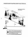
SLOPE OPERATION
.
Slopes are a major factor related to loss-of-control
and
tipover accidents, which can result in severe injury or death.
All slopes require extra caution, If you cannot back up the
slope or if you feel uneasy on it, do not mow it.
•
DO"
o
,
,
•
•
o
o
•
•
CHILDREN
Mow up and down slopes, not across.
Remove obstacles such as rocks, tree limbs, etc.
Watch for holes, ruts, or bumps. Uneven terrain could
overturn the machine. Tall grass can hide obstacles.
Use stow speed. Choose a low gear so that you wilt not have
to stop or shift while on the slope.
Follow the manufacturer's
recommendations
for wheel
weights or counterweights to improve stability.
Use extra care with grass catchers or other attachments.
These can change the stability of the machine.
Keep all movement on the slopes slowand gradual Do not
make sudden changes in speed or direction.
Avoid starting or stopping on a slope. If tires lose traction,
disengage the blades and proceed slowly straight down the
slope.
o
,
[_
SERVICE
Use extra care in handling gasoline and other fuels. They are
flammable and vapors are explosive.
Use only an approved container,
Never remove gas cap or add fuel with the engine
running. Allow engine to cool before refueling. Do not
smoke.
Never refuel the machine indoors,
Never store the machine or fuel container inside where
there is an open flame, such as a water heater.
Never run a machine inside a closed area.
Keep nuts and bolts, especially blade attachment bolts, tight
and keep equipment in good condition.
Never tamper with safety devices.
Check their proper
operation regularly.
Keep machine free of grass, leaves, or other debris build-up.
Clean oil or fuel spillage. Allow machine to cool before
storing.
Stop and inspect the equipment if you strike an object.
Repair, if necessary, before restarting.
Never make adjustments or repairs with the engine running.
Grass catcher components are subject to wear, damage, and
deterioration, which could expose moving parts or allow
objects to be thrown. Frequently check components and
replace with manufacturer's recommended parts, when necessary.
Mower blades are sharp and can cut. Wrap the blade(s) or
wear gloves, and use extra caution when servicing them.
Check brake operation frequently. Adjust and service as
required.
.......
Look for this_ symbol to point out im
portant
safety precautions,
tt means
CAUTION!!!
BECOMEALERT!!!
YOUR
SAFETY
DO NOT:
.
Donotturnonslopesunlessnecessary,
andthen,turns!owty
and gradually downhill, if possible.
•
Do not mow near drop-offs, ditches, or embankments. The
mower could suddenty turn over if a wheel is over the edge
of a ctiff or ditch, or if an edge caves in.
=
Do not mow on wet grass, Reduced traction could cause
sliding.
,
Do not try to stabilize the machine by putting your foot on the
ground.
•
Do not use grass catcher on steep slopes.
IS INVOLVED.
plu_
spark
wireand ptace wire where it cannot contact
spark plug in order to prevent accidenta!
starting when setting up, transporting,
adjusting or making repairs.
cAuT'o.:A,w0ys
disconnect
& WARNING
2
The engine exhaust from this product contains chemicals
known to the State of California to cause cancer, birth defects,
or other
reproductive
harm.
PRODUCT
CONGRATULA'TIONS
on your purchase of a Sears
Tractor. it has been designed, engineered and manufactured to give you the best possible dependability and
performance.
Shoutd you experience any probtem you cannot easily
remedy, please contact your nearest Sears Authorized
Service Center/Department.
We have competent, welltrained technicians and the proper tooIs to service or repair
this tractor.
Please read and retain this manual. The instructions will
enable you to assemble and maintain your tractor properly.
Always observe the "SAFETY RULES".
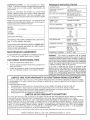
MODEL
NUMBER
9t7.258452
SPECMFJCATIONS
HORSEPOWER:
12.5
GASOUNE CAPACITY
AND TYPE:
1.25 GALLONS
UNLEADED REGULAR
OiL TYPE (API-SF/SGiSH):
SAE 30 (above 32°F)
SAE 5W-30 (below 32°F)
OIL CAPACITY:
3.0 PINTS
SPARK PLUG:
(GAP: .030")
CHAMPION
VALVE CLEARANCE:
INTAKE:
EXHAUST:
GROUND SPEED (MPH):
FORWARD:
1st
2nd
3rd
4th
5th
REVERSE:
SERIAL
NUMBER
DATE OF PURCHASE
TH E MODEL AND SERIAL NUMBERS WILL BE FOUND
ON A PLATE UNDER THE SEAT.
YOU SHOULD RECORD BOTH SERIAL NUMBER AND
DATE OF PURCHASE AND KEEP 1N A SAFE PLACE
FOR FUTURE REFERENCE.
MAINTENANCE
AGREEMENT
A Sears Maintenance
Agreement
is available on this product. Contact your nearest Sears store for details,
CUSTOMER
Read and observe
•
Foliow a regular schedule
using your tractor.
,
FoiIow the instructions
under "Customer Responsibilities" and "Storage" sections of this owner's manuat.
LIMITED
the safety
rules.
in maintaining,
caring for and
ONE YEAR WARRANTY
.005" - .007"
.009" - .0t 1"
1.0
2.1
3.1
4.0
5.1
1.6
TIRE PRESSURE:
FRONT:
REAR:
i4 PSi
12 PSI
CHARGING SYSTEM:
3 AMPS BATTERY
5 AMPS HEADLIGHTS
BATTERY:
AMPiHR:
MIN. CCA:
CASE SIZE:
BLADE BOLT TORQUE:
30-35 FT. LBS.
25
t90
U1R
WARNING:
This tractor is equipped with an internal
combustion engine and should not be used on or near any
unimproved forest-covered, brush-covered or grass-covered tand unless the engine's exhaust system is equipped
with a spark arrester meeting applicable local or state laws
(if any), tf a spark arrester is used, it should be maintained
in effective working order by the operator.
In the state of California the above is required by law
(Section 4442 of the California Public Resources Code).
Otherstates may have similar laws. Federal laws apply on
federal lands. A spark arrester for the muffler is available
through your nearest Sears Authorized Service Center/
Department (See REPAIR PARTS section of this manual).
RESPONStBILmES
,,
RJ19LM
ON CRAFTSMAN
RIDING EQUIPMENT
For one (1) year from the date of purchase, if this Craftsman Riding Equipment is maintained, lubricated and tuned up according
to the instructions in the owner's manuat, Sears will repair or replace, free of charge, any parts found to be defective in material
or workmanship.
This Warranty does net cover:
•
Expendable items which become worn during normal use, such as blades, spark plugs, air cleaners, belts, etc.
•
Tire replacement or repair caused by punctures from outside objects, such as nails, thorns, stumps, or glass.
•
Repairs necessary because of operator abuse, negligence, improper storage or accident or the failure to maintain the
equipment according to the instructions contained in the owner's manual.
•
Riding equipment used for commercial or rental purposes.
LIMITED 90 DAY WARRANTY
ON BATTERY
For ninety (90) days from date of purchase, if any battery included with this riding equipment proves defective in material or
workmanship and our testing determines the battery will not hold a charge, Sears will replace the battery at no charge.
IN-HOME WARRANTY SERVICE ON YOUR CRAFTSMAN RIDING EQUIPMENT IS AVAILABLE AT NO-CHARGE FOR 30
DAYS FROM THE DATE OF PURCHASE.
PLEASE CONTACT YOUR NEAREST SERVICE CENTER. AFTER 30 DAYS
FROM THE DATE OF PURCHASE, WARRANTY SERVICE IS AVAILABLE BY TAKING YOUR CRAFTSMAN RIDING EQUIPMENT TO YOUR NEAREST SEARS SERVICE CENTER. (IN-HOME WARRANTY SERVICE WiLL STILL BE AVAILABLE
AFTER 30 DAYS FROM THE DATE OF PURCHASE BUT A STANDARD TRiP CHARGE WILL APPLY.) THIS WARRANTY
APPLIES ONLY WHILE THIS PRODUCT IS IN THE UNITED STATES.
This Warranty gives you specific iegat rights, and you may also have other rights which may vary from state to state.
SEARS,
ROEBUCK
AND CO., D/817 WA, HOFFMAN
3
ESTATES,
fL 60179
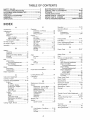
TABLE OF CONTENTS
SAFETY RULES ............................................................
2
PRODUCT SPECIFBCATJONS ...................................... 3
CUSTOMER RESPONSiBiLITiES
..................... 3, 14-18
WARRANTY ..................................................................
3
TRACTOR ACCESSORIES .......................................... 5
ASSEMBLY ................................................................
7-9
OPERATION ...........................................................
t0-! 3
MAINTENANCE SCHEDULE ......................................
14
SERVJCE AND ADJUSTMENTS ............................ 19-24
STORAGE ...................................................................
25
TROUBLESHOOTING ............................................
26-27
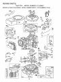
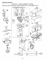
REPAIR PARTS - TRACTOR ................................. 30-47
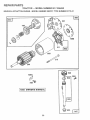
REPAIR PARTS - ENGINE .................................... 48-52
PARTS ORDERING/SERVICE ................ BACK COVER
NDEX
A
Accessories ...........................................
E
E_ectricaJ:
Interlocks and Relays .................. 23
Adjustments:
Schematic .................................... 29
Brake ............................................
2I
Wiring Diagram ............................ 30
Carburetor ....................................
24
Mower
Engine:
Front-To-Back.........................
20
Air Filter ........................................
17
Side-To-Side ........................... 20
Air Screen .................................... 17
Throttle Control Cable .................. 23
Cooling Fins, Engine .................... 17
Oil Change ................................... 16
Air Filter, Engine ..................................
17
Oil Level .................................. 12,16
Air Screen, Engine .............................. 17
Oil Type ........................................
16
Assembly ............................................
7-9
Preparation .................................. 12
Repair Parts ............................ 48-52
B
Starting .........................................
13
Storage ........................................ 25
Battery:
Charging ........................................
8
F
Cleaning .......................................
16
Starting with Weak Batter,i .......... 22
Filter:
Storage ........................................
25
Air Filter ........................................
t7
Terminals .....................................
t6
Fuel ..............................................
18
Belt:
Fuel:
Motion Drive
Type .............................................
12
Removal/Replacement ............ 2t
Storage ........................................
25
Mower Blade{s)
Fuse ....................................................
23
Removal/Replacement ............ 2!
Blade:
H
Sharpening ...................................
15
Hood Removal/Installation .................. 23
Replacement ................................ 15
Brake Adjustment ................................
5
21
L
C
Carburetor Adjustment ........................ 24
Controls, Tractor .................................
10
Leveling Mower Deck ..........................
Lubrication:
Chart ............................................
20
Customer Responsibilities .............. 15-t 8
Engine:
Air Filter ....................................
17
Air Screen, Engine ................... 17
Cooling Fins, Engine ................ !7
Engine Oil ................................ ! 6
Fuel Filter ................................. 18
Spark Plug(s) ........................... 18
Tractor:
Battery ......................................
16
Blade ........................................
15
Lubrication Chart ...................... 14
Maintenance Schedule ............ 14
Tire Care .......................... 8,15,22
Transaxle .................................
16
Cutting Height, Mower ......................... 11
Maintenance Schedule ....................... 14
Mower:
Adjustment, Front-to-Back ........... 20
Adjustment, Side-to-Side ............. 20
Biade Sharpening ........................ 15
Blade Replacement ...................... 15
Cutting Height .............................. 11
lnstafiation .................................... 19
Operation ..................................... 12
Removal .......................................
19
Mowing Tips ........................................
'13
Muffler .................................................
18
Spark Arrester ........................... 3,40
I4
M
O
Oil:
Cold Weather Conditions ........ t 2,16
Engine ..........................................
16
Storage ........................................
25
4
Operation .......................................
10-13
Operating Mower ................................
12
Options:
Accessories ................... .................. 5
Spark Arrester ........................... 3,40
P
Parking Brake .................................
t0-11
Parts Bag ..............................................
6
Parts, Replacement/Repair
............ 30-47
Product Specifications ........................... 3
R
Repair Parts ...................................
30-47
S
Safety Rules ..........................................
Seat .......................................................
2
8
Service and Adjustments ............... t9-24
Carburetor ....................................
24
Fuse ............. :...............................
23
Hood Removal/Installation ........... 23
Motion Drive Belt
Removal/Replacement
............ 21
Mower Belt(s}
Removal/Replacement
............ 21
Mower Adjustment
Front4o-Back .......................... 20
Side-to-Side ............................ 20
Mower Removal ........................... I9
Tire Care ..............................
8,15,22
Slope Guide Sheet ..............................
51
Spark Plug(s) ......................................
18
Specifications ........................................
3
Starting the Engine ........................ t2-13
Steering Wheel .................................
7,22
Stopping the Tractor ............................ 1t
Storage ................................................
25
T
Throttle Control Cable Adjustment ...... 24
Tires ............................................
8,15,22
Trouble Shooting Chart .................. 26-27
Transaxle ............................................
t6
W
Warranty ................................................
Wiring Diagram ...................................
Wiring Schematic ................................
3
30
29
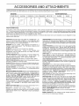
ACCESSO
meg AN
ATTACH
ENTS
These accessories and attachments were available through most Sears retail outlets and service centers when the tractor was purchased,
Most Sears stores can order these items for you when you provide the model number of your tractor.
ENGINE
SPARK PLUG
MAINTENANCE
GAS CAN
ENGINE OiL
FUEL STAB:_LIZER
AiR FDLTEFI
f
BLADES
BELTS
]
1
I
PERFORMANCE
Sears offers a wide variety of attachments that fit your tractor.
you. This Listwas current at the time of publication; however,
may be made in these attachments, or some may no longer
accessories and attachments
that are available for your
Most of these attachments
attaching and detaching.
Many of these are listed below with brief explanations of how they can help
it may change in future years - more attachments may be added, changes
be available or fit your model. Contact your nearest Sears store for the
tractor,
do not require additional hitches or conversion kits (those that do are indicated) and are designed for easy
AERATOR promotes deep root growth for a heattky lawn. Tapered 2.5-inch steel spikes mounted on 10-inch diameter discs
puncture holes in soil at close intervals to fet moisture soak in.
Steel weight tray for increased penetration.
BAGGER lets you collect
grass clippings and leaves for a
healthier, heater looking lawn. Two Permanex containers hold
30-gallon plastic bags.
BUMPER protects front end of tractor from damage.
CARTS make hauling easy. Variety of s_zes available, plus
accessories such as side panel kits, toot caddy, cart cover,
protective mat and dolly.
CORING AERATOR takes small plugs out of soil to allow moisture and nutrients to reach grass roots. 36-inch swath, 24
hardened steel coring tips. 150 lb. capacity weight tray.
EASY OIL DRAIN VALVE makes oil changes easier, faster.
FRONT NOSE ROLLER canters in front of mower deckto reduce
chances of "scalping" on uneven terrain.
GANG HITCH lets you tow 2 or3 pull-behind attachments at once,
such as sweepers, dethatchers, aerators (not for use with rollers,
carts or other heavy attachments).
GAUGE WHEELS on both sides of the mower deck reduce
chances of "scalping" on uneven terrain. For mower decks not so
equipped.
MULCH RAKE/DETHATCHER
loosens soil and flips thatch and
matted leaves to lawn surface for easy pickup. Twenty spring tine
teeth. Usefulto prepare bare areas forseeding. Availablefor front
or rear mounting.
HIGH PERFORMANCE
REEL-ACTION
SPRING TINE DETHATCHER
covers 364nch wide path and
tosses thatch into large hopper. Mounts behind tractor.
SNOW BLADE forsnow removal only. 14-inch high, 48-inch wide
btade clears 42-inch path when angled left or right. Raises, lowers
with side lever. Adjustable skids; replaceable, reversible scraper
bar. (Use with tire chains and wheeI weights and/or rear drawbar
weight.)
SNOWTHROWER has 40-inch swath. Drum-type auger handles
powdery and wet/heavy snow. Mounts easily with simple pin
arrangement. Discharge chute adjusts from tractor seat. 6-inch
diameter spout discharges snow t0 to 50 feet. Lift controlled at
tractor seat. (Use witt_ chains and whee! weights and/or rear
drawbar weight.)
SPRAYERS use 12-volt DC electric motor that connects to the
tractor battery or other !2-volt source.
Includes booms for
automatic spraying and hand held wand for spot spraying. Wand
has adjustable spray pattern. For applying herbicides, insecticides, fungicides and liquid fertilizers.
SPREADER!SEEDERS
make seeding, fertilizing, and weed killing easy. Broadcast spreaders are also useful for granular deicers and sand.
SWEEPERS let you collect grass clippings and leaves.
TILLER has 5 hp engine and 36-inch swath to prepare seed beds,
cultivate and compost garden residue. Tiller has its own built-in
lift and depth controi system and does NOT require a sleeve hitch.
Fits any lawn, yard or garden tractor. Simply hook up to the tractor
drawbar and go!
Optional
accessories
convert unit for
dethatching, aerating, hiiiing...without tools.
TIRE CHAINS are heavy duty; closely spaced extra-large cross
links give smooth ride, outstanding traction.
TRACTOR CAB has heavy duty vinyI fabric over tubular steel
frame, ABS plastic top; clear plastic windshield offers 360 degree
visibility. Hinged metal doors with catch. Keeps operator warm
and dry. Remove vinyl sides and windshields for use as sun
protector in summer. Optional accessories
include:
tinted/
tempered solid safety glass windshield with hand operated wiper;
12-vott amber caution light for mounting on cab top.
VACS for powerfu! collection of heavy grass clippings and leaves.
Optional wand attachment to pick up debris in hard-to-reach
places. VAC/CHIPPER includes a chipper-shredder.
WEIGHT BRACKET for drawbar for snow removal applications.
Uses (1) 55 Ib. weight.
MULCHING CLOSE-OUT PLATE KIT, once installed, lets you
mulch, discharge or bag clippings (bagger optional) without
changing blades. For models not equipped as 3-in-1 Convertible
mowers.
See "MOWER" in the Repair Parts section of this
manual.
RAMP TOPS AND FEET let you load and unload tractor from a
pickup truck. Use with 2 x 8 or 2 x 10 tumber.
ROLLER for smoother lawn surface.
36-inch wide, 18-inch
diameterwater-fight drum holds up to 390 lbs. of weight. Rounded
edges prevent harm to tuff. Adjustable scraper automatically
cleans drum.
WHEEL WEIGHTS for rear wheels provide needed traction for
snow removal or dozing heavy materials.
5
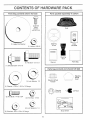
CONTENTS
Parts Bag contents
OF HA
DWA
shown fuji size
E PACK
Parts packed
separately
Jn carton
(2) Sheet
Metal
Screws
#10-t6 x 1/2
(1) Large Flat Washer
_
1)
Steering
Wheel
(1) Locknut 3/8-24
Video
Cassette
Steering
Boot
f
,!
Manual
(1) Hex Bolt 112-13 x 1
Parts Bag
(1) Shoulder Bolt 5/16-18
Parts bag contents
_
'-_
(1) Lock Washer
(t) Washer
17/32 x t-3/t6
1/2
Steering Wheel
Adapter
not shown
f
\
•
,,
(2) Keys
Bushing
teering
(2) Hex Bolts 1/4-20 x 3/4
(2) Hex Nuts t/4-20
(2) Washers
Steering
Wheel
Insert
x 12 Gauge
_
__1
full size
(2) Lock Washers
9/32 x 5/8 x 16 Gauge
!/4
Slope Sheet
i
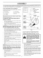
ASSEMBLY
Your new tractor has been assembled at the factory with exception of those parts left unassembied for shipping purposes.
To ensure safe and proper operation of your tractor aIl parts and hardware you assemble must be tightened securely. Use
the correct tools as necessary to insure proper tightness.
TOOLS
REQUIRED
FOR ASSEMBLY
A socket wrench set will make assembly easier. Standard
wrench sizes are listed.
(1) 5/t6" wrench
(I) 9/!6" wrench
(2) 7/16" wrenches
Tire pressure gauge
(1) 1/2" wrench
Utility knife
(1) 3/4" wrench
/
When right and left hand are mentioned in this manual, it
means when you are in the operating position (seated
behind the steering wheel).
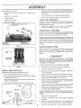
STEERING
WHEEL
TO REMOVE TRACTOR FROM CARTON
STEERING
UNPACK
Remove all accessible loose parts and parts cartons
from carton (See page 6).
o
Cut along lines on carton, from top to bottom, all four
corners of carton and lay panels flat.
-
Check for any additional loose parts or cartons and
remove.
TABS
,_REW
STEERING
SHAFT
(.
POSITION)
STEER{NG
ATTACH
(SHIPPING
WHEEL
/
BOOT
BEFORE ROLMNG TRACTOR OFF SKiD
STEERING
STEERING
BUSHING
ADAPTER
CARTON
•
•
" .......................i....
1
/
(See Fig. 1)
' '
(
PosmoN)
TAB
.......... 2:22_;
.... ,',
SLOT
,
Slide the steering bushing over the steering shaft.
,
Raise steering shaft forward until screw holes in dash
line up with steering bushing, install two (2) sheet
metal screws and tighten securely.
,
Position steering boot over steering shaft.
HOW TO SET UP YOUR TRACTOR
,
Place tabs of steering boot over tab slots in dash and
push down to secure.
CONNECT
•
,,
FIG. 1
Slide steering wheel adapter onto upper steering shaft.
Position front wheels of the tractor so they are pointing
straight forward.
Assemble large fiat washer and 3/8-24 locknut and
tighten securely.
,
Snap steering wheel insert into center of steering
wheel.
Remove cardboard packing from seat pan and lift seat
pan to raised position.
•
,
Press tift lever plunger and raise attachment lift lever to
its highest position.
Release parking brake by depressing clutch/brake
pedal.
•
o
Place gearshift lever in neutral (N) position.
Rolt tractor backwards off skid.
o
Remove banding holding discharge guard up against
tractor.
Open battery box door and remove protective plastic.
Remove terminal protective caps and discard.
TO ROLL TRACTOR OFF SKiD (SEE OPERATION SECTION FOR LOCATRON AND FUNCTiON OF CONTROLS)
•
2 and 3)
Positive terminal must be connected
first to prevent sparking from accidental grounding.
Remove protective materials from tractor hood and
grill.
IMPORTANT:CHECK FOR AND REMOVE ANY STAPLES
IN SKID THAT MAY PUNCTURETIRESWHERETRACTOR
tS TO ROLL OFF SKID.
,,
(See Figs.
CAUTION: Do not short battery terminals by allowing a wrench or any other
object to contact both terminals at the
same time. Before connecting battery,
remove metal bracelets,
wristwatch
bands, rings, etc.
Position steering wheel so cross bars are horizontal
(left to right) and slide onto adapter.
•
BATTERY
if this battery is put into service after month and year
indicated on label (label located between terminals)
charge batten.7for minimum of one hour at 6-! 0 amps.
First connect RED battery cable to positive (+) terminal
with hex bolt, flat washer, lock washer and hex nut as
shown. Tighten securely.
o
Connect BLACK grounding cable to negative (-) terminal with remaining hex bolt, flat washer, lock washer
and hex nut. Tighten securely.
,, Close battery box door.
7
BLY
ASSE
Slide seat until a comfortable position is reached which
allows you to press clutch/brake pedal all the way down
(See Fig. 8).
Open battery box door for:
_
inspection
ware).
for secure connections
(to tighten hard-
Get off seat without moving its adjusted position.
Inspection for corrosion.
o
Raise seat and tighten adjustment bolt securely.
Testing battery.
CHECK TIRE PRESSURE
Jumping (if required).
The tires on your tractor were overinfiated
shipping purposes. Correct tire pressure
best cutting performance.
Reduce [ire pressure to PSi shown
SPECIFICATIONS" on page 3 of this
Periodic charging.
TIVE CAPS
ISCARD TERMINAL
_[_
PROTEC-
at the factory for
is important for
in "PRODUCT
manual.
WASHER
!
HEX
FLAT
CHECK DECK
LEVELNESS
For best cutting results, mower housing should be properly
leveled. See "TO LEVEL MOWER HOUSING" in the
Service and Adjustments section of this manual.
HEX
BOLT
CHECK FOR PROPER POSiTiON OF ALL BELTS
POSITIVE
(RED) CABLE
See the figures that are shown for replacing motion and
mower blade drive belts in the Service and Adjustments
section of this manual. Verify that the belts are routed
correctly.
NEGATIVE
(BLACK) CABLE
FiG. 2
CHECK
BRAKE
SYSTEM
After you learn how to operate your tractor, check to see
that the brake is properly adjusted. See "TO ADJUST
BRAKE" in the Service and Adjustments section of this
manual.
SEAT
PAN
,/CHECKLIST
BEFORE YOU OPERATE AND ENJOY YOUR NEW
TRACTOR, WE WISH TO ASSURE THAT YOU RECEIVE
THE BEST PERFORMANCE AND SA TfSFA CTtON FROM
THIS QUALITY PRODUCT.
BOX DOOR
PLEASE REVIEW THE FOLLOWING CHECKLIST:
FMG.3
v"
All assembly instructions have been completed.
,/
No remaining loose parts in carton.
_NSTALL SEAT (See Fig. 4)
¢"
Adjust seat before tightening adjustment boit.
o Remove cardboard packing on seat pan.
Battery is properly prepared and charged.
! hour at 6 amps).
(Minimum
v"
Seat is adjusted comfortably and tightened securely.
Place seat on pan and assemble shoulder bolt. Tighten
shoulder bolt securely.
v"
All tires are properly inflated. (For shipping purposes,
the tires were overinflated at the factory).
o
Assembfe adjustment bolt, Iockwasher and flat washer
loosely. Do not tighten.
v"
o
Lower seat into operating position and sit on seat.
Be sure mower deck is properly leveled side-to-side/
front-to-rear for best cutting results. (Tires must be
properly inflated for leveling).
Check mower and drive belts. Be sure they are routed
properly around pulleys and inside all belt keepers.
v"
v"
SEAT PAN
Check wiring. See that all connections are still secure
and wires are properly clamped.
WHILE LEARNING HOW TO USE YOUR TRACTOR, PAY
EXTRA A 7TENTION TO THE FOLLOWING IMPORTANT
ITEMS:
SHOULDER
BOLT
v"
v"
FLAT WASHER
ADJUSTMENT
BOLT
,/
LOCK WASHER
FIG, 4
8
v"
Engine oil is at proper level.
Fuel tank is filled with fresh, clean, regular unleaded
gasoline.
Become familiar with all controls _ their location and
function. Operate them before you start the engine.
Be sure brake system is in safe operating condition.
OPERATIO
These symbols may appear on your tractor or in literature supplied with the product. Learn and understand their meaning.
BATTERY
CAUTION OR
WARNING
REVERSE
FORWARD
FAST
SLOW
ENGINE ON
ENGINE OFF
OIL PRESSURE
CLUTCH
LIGHTS ON
OVER TEMP
LIGHT
FUEL
CHOKE
MOWER HEIGHT
DIFFERENTIAL
LOCK
PARKING BRAKE
LOCKED
REVERSE
MOWER LIFT
NEUTRAL
ATTACHMENT
CLUTCH ENGAGED
HIGH
LOW
ATTACHMENT
CLUTCH DISENGAGED
UNLOCKED
PARKING BRAKE
IGNITION
HYDROSTATIC FREE WHEEL
(Hydro Models only)
DANGER, KEEP HANDS AND FEET AWAY
9
OPERA
0
KNOW YOUR TRACTOR
READ THiS OWNER'S
MANUAL
AND SAFETY
RULES
BEFORE
OPERATING
YOUR TRACTOR
Compare the itlustrations with your tractor to familiarize yourseif with the locations of various controls and adjustments.
this manual for future reference.
ATTACHMENT
CLUTCH LEVER
IGNITION
SW_TCH
THROTTLFJCHOKE
CONTROL
Save
LIGHT SWITCH
LIFT LEVER PLUNGER
ATTACHM ENT
LIFT LEVER
CLUTCH!BRAKE
PEDAL
MOWER DECK
HEIGHT ADJUSTMENT POSITIONS
=
PARKING
BRAKE
I
GEARSHIFT
LEVER
'
FIG. 5
Our tractors conform to the safety standards of the American Nationaf Standards Institute.
GEARSHIFT LEVER: Selects the speed and direction of
tractor.
ATTACHMENT CLUTCH LEVER: Used to engage the
mower blades, or other attachments mounted to your
tractor.
LIGHT SWITCH:
ATTACHMENT LIFT LEVER: Used to raise, lower and
adjust the mower deck or other attachments mounted to
your tractor.
MFT LEVER PLUNGER: Used to release attachment lift
lever when changing its position.
Turns the headlights on and off.
THROTTLE/CHOKE
CONTROL:
controlling engine speed.
Used for starting and
CLUTCH/BRAKE PEDAL: Used fordectutching
ing the tractor and starting the engine.
PARKING BRAKE:
brake position.
Locks clutch/brake
and brak -
IGNITION SWITCH:
engine.
pedai into the
I0
Used for starting and stopping the
OPERATION
The operation of any tractor can resu}t in foreign objects thrown into the eyes, which
can resuit in severe eye damage. Always wear safety gtasses or eye shields white
operating your tractor or performing any adjustments or repairs. We recommend a wide
vision safety mask over the spectacles or standard safety glasses.
NOTE: Under certain conditions when tractor is standing
idle with the engine running, hot engine exhaust gases may
cause "browning" of grass. To eliminate this possibility,
always stop engine when stopping tractor on grass areas.
HOW TO USE YOUR TRACTOR
TO SET PARKING
BRAKE
(See Fig, 6)
Your tractor is equipped with an operator presence sensing
switch. When engine is running, any attempt by the
operator to leave the seat without first setting the parking
brake wilt shut off the engine.
•
Depress clutch/brake
and ho_d°
tract_'_-r=c-om_
Aiwoys
stop
described above, before
_
pedal into full "BRAKE" position
position;
_eavto empty
her, etc.
TO USE THROTTLE
Place parking brake lever in "ENGAGED" position and
release pressure from clutch/brake pedal. Pedal should
remain in "BRAKE" position. Make sure parking brake
will hold tractor secure.
THROTTLE/CHOKE
CONTROL
ing the operator's
CONTROL
(See Fig. 6)
Always operate engine at full throttle.
ATTACHMENT CLUTCH LEVER
"ENGAGED" POSITION
"DISENGAGED"
POSITION
•
Operating engine at less than full throttle reduces the
battery charging rate.
o
Full throttle offers the best bagging and mower performance.
TO MOVE FORWARD
(See Fig. 6}
PARKING BRAKE
"ENGAGED" POSITION
AND BACKWARD
The direction and speed of movement
gearshift lever.
"DISENGAGED"
POSITION
GEARSHIFT
LEVER
is controlled by the
-
Start tractor with clutch/brake pedal depressed and
gearshift lever in neutral (N) position.
o
Move gearshift lever to desired
position.
•
S{owty release clutch/brake pedai to start movement.
IMPORTANT: BRING TRACTOR TO A COMPLETE STOP
BEFORE SHIFTING OR CHANGING GEARS. FAILURE
TO DO S© WILL SHORTEN THE USEFUL LIFE OF YOUR
TRANSAXLE.
CLUTCHIBRAKE
PEDAL
"DRIVE" POSITION
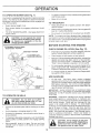
TO ADJUST MOWER
(See Fig. 5)
FIG. 6
STOPPING
The position of the attachment
cutting height.
(See Fig. 6)
MOWER BLADES •
Move attachment clutch lever to "DISENGAGED"
sition.
po-
,
lever to neutral (N) position.
Move throttle control to slow position.
NOTE: Failure to move throttle control to slow position and
allowing engine to idle before stopping may cause engine
to "backfire".
Turn ignition key to "OFF" position and remove key.
Atways remove key when leaving tractor to prevent
unauthorized use.
•
lift lever determines
the
Grasp lift lever.
•
Press plunger with thumb and move lever to desired
position.
Thecutting height range is approximately 1-1/2to 4". The
heights are measured from the ground to the blade tip with
the engine not running. These heights are approximate
and may vary depending upon soil conditions, height of
grass and types of grass being mowed.
Depress clutch/brake pedal into full "BRAKE" position.
•
Move gearshift
ENGINE
HEIGHT
=
GROUND DRIVE •
CUTTING
Never use choke to stop engine.
1!
,
The average lawn should be cut to approximately 2-1/2
inches during the cool season and to over 3 inches
during hot months. For healthier and better looking
lawns, mow often and after moderate growth.
,
For best cutting performance, grass over 6 inches in
height should be mowed twice. Make the first cut
relatively high; the second to desired height.
OPERATION
TO OPERATE
MOWER
(See Fig. 7)
Your tractor is equipped with an operator presence sensing
switch. Any attempt by the operator to leave the seat with
the engine running and the attachment clutch engaged wiil
shut off the engine.
o
To restart movement, slowly reiease parking brake and
clutch/brake pedal.
o
Make all turns slowly
TO TRANSPORT
Raise attachment lift to highest position with attachment tift controi,
o
Select desired height of cut.
°
Start mower blades by engaging attachment dutch
control.
o
o
TO STOP MOWER BLADES - disengage attachment
clutch control.
When pushing or towing your tractor, be sure gearshift
lever is in neutrat (N) position.
•
Do not push or tow tractor at more than five (5) MPH.
NOTE: To protect hood from damage when transporting
your tractor on atruckor atrailer, be sure hood is closed and
secured to tractor. Use an appropriate means of tying hood
to tractor (rope, cord, etc.).
BEFORE
ATTACHMENT CLUTCH LEVER
"DISENGAGED"
POSITION
STARTING
CHECK ENGINE
THE ENGINE
OiL LEVEL
(See Fig, 12)
POSITION
-
The engine in your tractor has been shipped, from the
factory, already filled with summer weight oil.
ATTACHMENT LIFT
LEVER HIGH POSITION
-
Check engine oil with tractor on level ground.
-
Remove oil fiIl cap/dipstick and wipe clean, reinsert the
dipstick and screw cap tight, wait for a few seconds,
remove and read oil level. If necessary, add oil until
"FULL" mark on dipstick is reached. Do not overfill.
*
For cotd weather operation you shoutd change oil for
easier starting (See "OIL VISCOSITY CHART" in the
Customer ResponsibiIities section of this manual).
-
To change engine oil, see the Customer Responsibilities section in this manual.
"ENGAGED"
LOW
POSITION
ADD GASOLINE
R.H.
RUNNER
•
/
Fill fuet tank. Use fresh, clean, regular unleaded
gasoline with a minimum of 87 octane. (Use of leaded
gasoline will increase carbon and lead oxide deposits
and reduce valve life). Do not mix oil with gasoline,
Purchase fuel in quantities that can be used within 30
days to assure fuel freshness.
iMPORTANT: WHEN OPERATING iN TEMPERATURES
BELOW 32°F(0"C), USE FRESH, CLEAN WINTER GRADE
GASOLINE TO HELP iNSURE GOOD COLD WEATHER
STARTING.
DISCHARGE
GUARD
/
FiG. 7
TO OPERATE
ON HILLS
WARNING:
Experience indicates that alcohol blended
fuels (called gasohol or using ethanol or methanol) can
attract moisture which leads to separation and formation of
acids during storage. Acidic gas can damage the fuel
system of an engine while in storage. To avoid engine
problems, the fuel system should be emptied before storage of 30 days or longer. Drain the gas tank, start the
engine and let it run until the fuel lines and carburetor are
empty. Use fresh fuel next season. See Storage Instructions for additional information.
Never use engine or
carburetor cleaner products in the fuel tank or permanent
damage may occur.
Choose the slowest speed before starting up or down
hills.
,
Avoid stopping or changing speed on hills.
•
If slowing is necessary, move throttle control lever to
slower position.
If stopping is absolutely necessary, push clutch/brake
pedat quickly to brake position and engage parking
brake.
__
_:
_
Move gearshift lever to 1st gear. Be sure you have
allowed room for tractor to rol! slightly as you restart
movement.
! _
t2
____
.
Fill to bottom of gas tank
fil_erneck. Do notoverfil!. Wipeoffany
spilled oil or fuel Do not store, spill or
use gasoline near an open flame.
OPERATEON
TO START
ENGINE
MOWING
(See Fig. 6)
When starting the engine for the first time or if the engine
has run out of fuel, it wili take extra cranking time to move
fuel from the tank to the engine.
o
Sit on seat in operating position, depress clutch/brake
pedal and set parking brake.
o
Piace gear shift lever in neutral (N) position.
o
Move attachment clutch to "DISENGAGED" position.
°
Move throttle control to choke position.
Insert key into ignition and turn key clockwise to"START"
position and release key as soon as engine starts. Do
not run starter continuously for more than fifteen seconds per minute. If the engine does not start after
several attempts, move throttle control to fast position,
wait a few minutes and try again. If engine still does not
start, move the throttle control back to the choke
position and retry.
WARM WEATHER STARTING (50 ° F and above)
•
When engine starts, move the throttle control to the fast
position.
.
The attachments and ground drive can now be used. If
the engine does not accept the load, restart the engine
and allow it to warm up for one minute using the choke
as described above.
COLD WEATHER STARTING ( 50 ° F and below)
°
o
•
Tire chains cannot be used when the mower housing
is attached to tractor.
•
Mower should be properly leveled for best mowing
performance. See "TO LEVEL MOWER HOUSING" in
the Service and Adjustments section of this manual.
o
Use the runner on the right hand side of mower as a
guide. The blade cuts approximately an inch outside
the runner (See Fig. 7)
The left hand side of mower should be used for trim*
ruing.
-
Note: Before starting, read the warm and coid starting
procedures below.
When engine starts, allow engine to run with the throttle
control in the choke position until the engine runs
roughly, then move throttle control to fast position. This
may require an engine warm-up period from several
seconds to several minutes, depending on the temperature.
The attachments carl also be used during the engine
warm-up period.
TiPS
o
Drive so that clippings are discharged onto the area
that has been cut. Have the cut area to the right of the
machine. This will result in a more even distribution of
clippings and more uniform cutting.
°
When mowing large areas, start by turning to the right
so that clippings witl discharge away from shrubs,
fences, driveways, etc. After one or two rounds, mow
in the opposite direction making left hand turns until
finished (See Fig. 8).
•
If grass is extremely tat!, it should be mowed twice to
reduce toad and possible fire hazard from dried clippings. Make first cut relatively high; the second to the
desired height.
•
Do not mow grass when it is wet. Wet grass will piug
mower and leave undesirable clumps. Allow grass to
dry before mowing.
o
Always operate engine at full throttle when mowing to
assure better mowing performance and proper discharge of material. Regulate ground speed by selecting a low enough gear to give the mower cutting
performance as well as the quality of cut desired.
°
When operating attachments, select a ground speed
that will suit the terrain and give best performance of
the attachment being used.
.
NOTE: if at a high altitude (above 3000 feet) or in cotd
temperatures (below 32 F) the carburetor fuel mixture may
need to be adiusted for best engine performance. See "TO
ADJUST CARBURETOR" in the Service and Adjustments
section of this manual.
FIG. 8
t3
CUSTO
MAINTENANCE
E
LmES
ESPONS
SCHEDULE
FILL 1N DATES
AS YOU COMPLETE
REGULAR SERVICE
SERVICE DATES
Check Brake Operation
'3.................
Check Pressore
IJ
Check for Loose Fasteners
$f
I V' !
_€_7
m
Sharpen/Replace
Lubrication
Mower Blades
Chart
f
Check Battery Level/Recharge
Clean Battery
and Terminals
Check Transaxte
v'
Cooling
Adjust
Blade Belt{s) Tension
Adjust
Motion Drive Beit(s) TensTon
_5
i
Check Engine
Change
E
e/
Engine Oil
Clean Air Filter
CIean Air Screen
Inspect
Replace
Muffler/Spark
Attester
!
jr'
Oil Fitter (If equipped)
Clean Engine
1
2
3
4
v'
Off Level
Cooling
Fins
Replace
Spark Plug
Replace
Air Fitter Paper Cartridge
Replace
Fue, Filter
_#_2
_
1 6_'2
i
_
- Change more often when operating under a heavy load or in high ambienl temperatures.
_ Service more ofte_ when operating in dirty or dusty conditions.
_ if equipped with oil fi_ter, change oif every 50 hours.
- RepIace bfades more often when mewing Jn sandy soil.
GENERAL
6/'
....
5. if equippedwith adjustable system.
6 - Not requiredif equipped with ma}ntenance-freebattery.
7 - Tightenfront axle pivot bolt to 35 ftAbs, maximum.
Do notovertighten.
LUBRICATION
RECOMMENDATIONS
C) SPINDLE ZERK _
The warranty on this tractor does not cover items that have
been subjected to operator abuse or negligence.
To
receive full value from the warranty, operator must maintain
tractor as instructed in this manual.
(_) FRONT
BEARING
CHART
_
ZERK
SPINDLE
BEARING
ZERK (_
ZERK
Some adjustments wilt need to be made periodically to
properly maintain your tractor.
ENGINE (_)
AI! adjustments in the Service and Adjustments section of
this manual should be checked at least once each season.
G
Once a year you should replace the spark plug, clean
or replace air filter, and check blades and belts for
wear. A new spark plug and clean air filter assure
proper air-fuel mixture and help your engine run better
and last longer.
BEFORE
EACH
CLUTCH
PIVOT(S)
USE
,
Check engine oil level.
,
Check brake operation.
•
•
Check tire pressure.
Check for loose fasteners.
(_ SAE 30 OR 10W30 MOTOR OiL
(_) GENERAL
PURPOSE GREASE
REFER TO CUSTOMER
RESPONSIBILITIES
"ENGINE"
SECTION
IMPORTANT:
DO NOT OIL OR GREASE THE PIVOT POINTS
WHICH HAVE SPECIAL NYLON BEARINGS.
VISCOUS
LUBRICANTS WILL ATTRACT DUST AND DiRT THAT WILL SHORTEN
THE LiFE OF THE SELF-LUBRICATING
BEARINGS.
IF YOU
FEEL THEY MUST BE LUBRICATED,
USE ONLY A DRY, POWDERED GRAPHITE
TYPE LUBRICANT
SPARINGLY.
i4
CUSTOM
SI IL
RESPO
IES
TRACTOR
BLADE
Always observe safety rules when performing any maintenance.
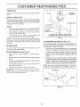
BRAKE
OPERATION
If tractor requires more than six (6} feet stopping distance
at high speed in highest gear, then brake must be adjusted.
(See "TO ADJUST BRAKE" in the Service and Adjustments section of this manual).
FLAT WASHER
TIRES
o
LOCK WASHER
Maintain proper air pressure in all tires (See "PRODUCT SPECIFICATIONS" on page 3 of this manual).
o
Keep tires free of gasoline, oil, or insect control chemicals which can harm rubber.
o
Avoid stumps, stones, deep ruts, sharp objects and
other hazards that may cause tire damage.
HEXBOLT
(GRADE
*A GRADE 8 HEAT TREATED BOLT CAN BE
IDENTIFIED BY SgX LINES ON THE BOLT HEAD.
FIG. 9
NOTE: To seat tire punctures and prevent flat tires due to
slow leaks, tire sealant may be purchased from your local
parts dealer. Tire sealant also prevents tire dry rot and
TO SHARPEN
corrosion,
BLADE
BLADE
(See Fig. 10)
Care should be taken to keep the blade balanced. An
unbalanced biade will cause excessive vibration and eventual damage to mower and engine.
CARE
For best results mower blades must be kept sharp. Reptace bent or damaged btades.
=
The btade can be sharpened with a file or on a grinding
wheel. Do not attempt to sharpen while on the mower.
BLADE
o
To check blade balance, you will need a 5/8" diameter
steel bolt, pin, or a cone balancer. (When using acone
balancer, follow the instructions supplied with balancer).
•
Slide blade on to an unthreaded portion of the steel bolt
or pin and hold the bolt or pin parallel with the ground.
If blade is balanced, it should remain in a horizontal
position. If either end of the blade moves downward,
sharpen the heavy end until the blade is balanced.
o
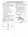
REMOVAL
(See Fig. 9)
Raise mower to highest position to allow access to
blades.
Remove hex bolt, lock washer and fiat washer securing
blade.
Instal1 new or resharpened blade with trailing edge up
towards deck as shown,
Reassemble hex bolt, lock washer and flat washer in
exact order as shown.
NOTE: Do not use a nail for balancing blade. The lobes of
the center hole may appear to be centered, but are not.
Tighten bolt securely (30-35 Ft. Lbs. torque).
IMPORTANT: BLADE BOLT IS GRADEBHEATTREATED.
/
CENTER HOLE
NOTE: We do not recommend sharpening blade - but if you
do, be sure the bIade is balanced.
/
/
/
/'
BLADE
5/8" BOLT
OR PiN
FIG. 10
!5
/
/
CUSTO
ESPONSJBILITIES
ER
NOTE: Although multi-viscosity oils (5W30, 10W30 etc.)
improve starting in cold weather, these multi-viscosity oils
wilt result in increased oil consumption when used above
32°R Check your engine oil level more frequently to avoid
possible engine damage from running tow on oil,
_!}ATTERY
Your tractor has a battery charging system which is sufficient for normal use. However, periodic charging of the
battery with an automotive charger will extend its life.
o
Keep battery and terminais clean,
o
Keep battery bolts tight,
Change the oil after every 25 hours of operation or at least
once a year if the tractor is not used for 25 hours in one year,
Check the crankcase oil level before starting the engine
and after each eight (8) hours of operation. Tighten oil fill
cap/dipstick securely each time you check the oil level.
Keep small vent holes open.
Recharge at 6-10 amperes for 1 hour.
TO CLEAN BATTERY AND TERMINALS
TO CHANGE ENGINE OIL (See Figs. 11 and 12)
Corrosion and dirt on the battery and terminals can cause
the battery to "leak" power.
o
o
o
Determine temperature range expected before oil change.
All oil must meet API service classification SF, SG, or SH.
Open battery box door.
Disconnect BLACK battery cable first then RED battery cable and remove battery from tractor.
Be sure tractor is on level surface.
Oit will drain more freety when warm,
Catch oil in a suitable container.
Rinse the battery with ptain water and dry.
e
Clean terminals and battery cable ends with wire brush
until bright.
,!1
Coat terminals with grease or petroleum jelly,
.
Remove drain piug.
Reinstall battery (See "CONNECT
Assembly section of this manual).
-
After oil has drained completely, replace oil drain plug
and tighten securely.
.
Refill engine with oil through oil fill dipstick tube. Pour
slowly. Do not overfill. For approximate capacity see
"PRODUCT SPECIFICATIONS" on page 3 of this
manual.
•
Use gauge on oil fill cap/dipstick for checking level. Be
sure dipstick cap is tightened securely for accurate
reading. Keep oil at "FULL" line on dipstick.
BATTERY" in the
V-BELTS
Check V-belts for deterioration and wear after I00 hours of
operation and replace if necessary. The belts are not
adjustable. Replace belts if they begin to slip from wear.
TRANSAXLE
COOLING
Remove oit fill cap/dipstick. Be careful not to allow dirt.
to enter the engine when changing oit.
Keep transaxle free from buitd-up of dirt and chaff which
can restrict cooling,
OIL FILL
CAP!DIPSTICK
ENGINE
LUBRICATION
Only use high quality detergent oil rated with API service
classification SF, SG, or SH. Select the oil's SAE viscosity
grade according to your expected operating temperature.
SAE VISCOSITY GRADES
OIL DRAIN
PLUG
!
.20 °
.30 o
0°
_20 °
TEMPERATURE
30 °
.10 o
32 °
40 °
6°
RANGE ANTICIPATED
60 _
10°
BEFORE
80°
20°
FIG. 12
100 _
30°
40 °
NEXT OIL CHANGE
FIG. 11
16
CUS'['OME
A1R FILTER
RESPONS!
(See Fig, 13)
CLEAN
Your engine will not run properly using a dirty air filter.
Clean the foam pre-cleaner after every 25 hours of operation or every season. Service paper cartridge every 100
hours of operation or every season, whichever occurs first.
RL
AIR SCREEN
ES
(See Fig. 14)
Air screen must be kept free of dirt and chaff to prevent
engine damage from overheating. Clean with a wire brush
or compressed air to remove dirt and stubborn dried gum
fibers.
Service air cleaner more often under dusty conditions.
ENGINE
COOLING
FiNS (See Fig. 14
o
Remove knob(s) and cover.
TO SERVICE PRE-CLEANER
Remove any dust, dirt or oil from engine cooling fins to
prevent engine damage from overheating.
•
Slide foam pre-cteaner off cartridge.
•
•
Wash it in liquid detergent and water.
Remove screws from blower housing and lift housing
and dipstick tube assembly off engine.
•
Squeeze it dry in a clean cloth.
Cover oil fill opening to prevent entry of dirt.
o
Saturate it in engine oil. Wrap it in clean, absorbent
cloth and squeeze to remove excess oil.
o
Use compressed air or stiff bristle brush to thoroughly
clean engine cooling fins.
•
If very dirty or damaged, replace pre-cteaner.
•
To reassemble, reverse above procedure.
o
Reinstall pre-cleaner over cartridge.
SCREWS
BLOWER HOUSING
Reinstall cover and secure with knob(s).
TO SERVICE CARTRIDGE
,
Remove cartridge nut.
•
Carefully remove cartridge to prevent debris from entering carburetor.
Clean base carefully to prevent
debris from entering carburetor.
•
Clean cartridge by tapping gently on fiat surface. If very
dirty or damaged, replace cartridge.
SCREWS
AiR SCREEN
DIPSTICK TUBE
ASSEMBLY
•
Reinstall cartridge, nut, precIeaner, cover and secure
with knob(s).
IMPORTANT:
PETROLEUM SOLVENTS, SUCH AS
KEROSENE, ARE NOT TO BE USED TQ CLEAN THE
CARTRIDGE. THEY MAY CAUSE DETERIORATION QF
THE CARTRIDGE. DO NQTOIL CARTRIDGE. DO NOT
USE PRESSURIZED
AIR TO CLEAN OR DRY
CARTRIDGE.
SPARK
PLUG
ENGINE COOLING
FIG. 14
CARTRtDGENUT
PAPER
CARTRIDGE
FOAM
PRE-CLEANER
FIG, 13
17
FINS
CUSTO
ER
ESPONSm ILITMES
MUFFLER
Inspect and replace corroded muffler and spark arrester (if
equipped) as it could create a fire hazard and/or damage.
SPARK
PLUGS
Replace spark plugs at the beginning of each mowing
season or after every 100 hours of operation, whichever
occurs first. Spark plug type and gap setting are shown in
"PRODUCT SPECIFICATIONS" on page 3 of this manual.
iN-LINE
FUEL FILTER
FUEL
FILTER
(See Fig. 15)
FIG. 15
The fuei filter should be replaced once each season. If fuel
filter becomes clogged, obstructing fuel flow to carburetor,
replacement is required.
.
With engine cool, remove filter and plug fuel line
sections.
•
Place new fuel filter in position in fuel line with arrow
pointing towards carburetor.
,
Be sure there are no fuel line leaks and clamps are
properly positioned.
•
CLEANING
•
Clean engine, battery', seat, finish, etc. of all foreign
matter.
,
Keep finished surfaces and wheels free of all gasoline,
oil, etc.
,
Protect painted surfaces with automotive type wax.
We do not recommend using a garden hose to clean your
tractor unless the electrical system, muffler, air filter and
carburetor are covered to keep water out. Water in engine
can result in a shortened engine life.
Immediately wipe up any spilled gasoline.
18
SERVICE AND ADJUSTMENTS
CAUTION:
BEFORE PERFORMING ANY SERVICE OR ADJUSTMENTS;
o
Depress clutch/brake
o
,
•
,
Paace attachment clutch in "DISENGAGED" position,
PEace gearshift lever in neutral (N) position.
Turn ignition key "OFF" and remove key,
Make sure the b_ades and ait moving parts have completemy stopped.
,
Disconnect
plug,
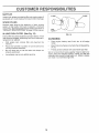
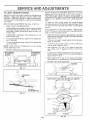
TO REMOVE
MOWER
pedal fully and set parking brake.
spark ptug wire from spark plug and place wire where it cannot come in contact with
(See Fig. t6)
CLUTCH ROD
Mower will be easier to remove from the right side of tractor.
,
•
Place attachment clutch in "DISENGAGED" position,
Move attachment Iift lever forward to tower mower to its
lowest position.
,
Roll belt off engine pulley.
Disconnect anti-sway bar from chassis bracket by
removing retainer spring.
•
Disconnect suspension arms from rear deck brackets
by removing retainer springs.
RETAINER
SUSPENSION
ARMS
RETAINER
Disconnect cIutch rod from clutch lever by removing
retainer spring.
o
LEVER
\
SPRINGS
Disconnect front tinks from deck by removing retainer
springs.
•
Raise lift lever to raise suspension arms. Slide mower
out from under tractor.
IMPORTANT: _FAN ATTACHMENT OTHER THAN THE
MOWER DECK IS TO BE MOUNTED ON THE TRACTOR,
REMOVE THE FRONT LINKS,
RETAINER
SPRING
TO INSTALL
ANTI-SWAY
MOWER
(See Fig. 16)
•
Raise attachment lift tever to its highest position.
•
Slide mower under tractor with discharge guard to right
side of tractor.
o
,
Lower lift lever to its lowest position.
InstaiI mower in reverse order of removal instructions.
BAR
FIG. !6
t9
SPRING
FRONT
LINKS
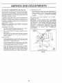
ADJUST
SERVICE A
TO LEVEL MOWER
HOUSING
ENTS
FRONT-TO-BACK
ADJUSTMENT
(See Figs, 19 and 20)
IMPORTANT:
DECK MUST BE LEVEL SiDE-TO-SIDE.
IF
THE FOLLOWING
FRONT-TO-BACK
ADJUSTMENT
tS
NECESSARY, BE SURE TO ADJUST BOTH FRONT LINKS
EQUALLY
SO MOWER
WiLL STAY LEVEL SIDE-TOSIDE.
Adjust the mower while tractor is parked on level ground or
driveway.
Make sure tires are properly inflated (See
"PRODUCT SPECIFICATIONS" on page 3 of this manual).
If tires are over or underinflated, you wilt not properly adjust
your mower.
To obtain the best cutting results, the mower housing
should be adjusted so that the front is approximately 1/8" to
1/2" iower than the rear when the mower is in its highest
position.
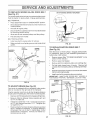
SIDE-TO-SIDE ADJUSTMENT (See Figs. 17 and 18)
,
Raise mower to its highest position.
•
At the midpoint of both sides of mower, measure height
from bottom edge of mower to ground. Distance "A" on
both sides of mower should be the same or within I/4"
of each other.
Check adjustment on right side of tractor. Measure distance "D" directly in front and behind the mandrel at bottom
edge of mower housing as shown.
•
If adjustment is necessary, make adiustment on one
side of mower only.
•
To raise one side of mower, tighten lift link adjustment
nut on that side.
Before making any necessary adjustments, checkthat
both front links are equal in length. Both links should be
approximately 10-3/8".
To lower one side of mower, loosen lift link adjustment
nut on that side.
NOTE: Three full turns of adjustment
mower height about t/8".
-
Recheck measurements
,
nut wilt change
o
after adjusting.
BOTTOM EDGE
OF MOWER TO
GROUND
BOTTOM EDGE
OF MOWER TO
GROUND
If links are not equal in fength, adjust one link to same
}ength as other link.
To lower front of mower loosen nut "E" on both front
links an equal number of turns.
When distance "D" is 1/8" to 1/2" lower at front than
rear, tighten nuts "F" against trunnion on both front
finks.
To raise front of mower, loosen nut"F" from trunnion on
both front links. Tighten nut "E" on both front Iinks an
equal number of turns.
When distance "D" is !/8" to 1/2" lower at front than
rear, tighten nut "F" against trunnion on both front links.
Recheck side4o-side adjustment.
GROUND LINE
FIG. 17
SUSPENSION
ARM
FIG. 19
BOTH FRONT LINKS MUST BE EQUAL IN LENGTH
J
LIFT LINK
ADJUSTMENT
NUT
FiG. 18
NUT "E"
FRONT LINKS
20
TRUNNION
FiG. 20
SERWCE A
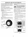
TO REPLACE
MOWER
BLADE
D ADJUSTMENTS
DRBVE BELT
WITH PARKING BRAKE "ENGAGED"
(See Fig, 21)
The mower blade drive belt may be replaced without tools.
Park the tractor on levef surface. Engage parking brake.
\
\
BELT REMOVAL Place attachment
clutch in "DISENGAGED"
position.
*
Move attachment lift tever fowvard to lower mower to its
lowest position.
,
Roll belt off engine pulley.
o
Disconnect R.H. suspension arm from rear deck bracket
by removing retainer spring,
o
Work belt off both mandrel pulleys and idler pulleys.
,
Pull belt away from mower.
JAM
NUT
OPERATING
ARM
BELT iNSTALLATION Install new belt in reverse order of removal.
,
Make sure belt is in all puIley grooves and inside all belt
guides.
IDLER
PULLEYS
MANDREL
FIG. 22
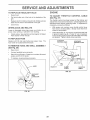
TO REPLACE
ENGINE
PULLEY
MOT!ON
DR!VE
BELT
(See Fig. 23)
Park the tractor on level surface. Engage parking brake.
For assistance, there is a belt installation guide decal on
bottom side of left footrest.
RETAINER
SPRING
/
Remove mower (See "TO REMOVE MOWER" in this
section of this manual.)
,
Remove upper belt keeper.
•
Remove belt from stationary idler and clutching idler.
Pull belt slack toward rear of tractor.
Remove belt
upwards from transaxle pulley by deflecting beit keepers.
,
Pull belt toward front of tractor and remove downwa rds
from around engine pulley.
install new belt by reversing above procedure.
IMPORTANT: MAKE SURE UPPER BELT KEEPER tS
POSITIONED PROPERLY BETWEEN LOCATOR TABS.
MANDREL
PULLEYS
FIG. 21
TO ADJUST
-
BRAKE
PU LLEY
CLUTCHING
IDLER
(See Fig. 22)
)CATOR
TABS
Your tractor is equipped with an adjustable brake system
which is mounted on the right side of the transaxle.
BELT
KEEPER
If tractor requires more than six (6) feet stopping distance
at high speed in highest gear, then brake must be adjusted.
aDLER
Depress clutch!brake pedal and engage parking brake.
=
Measure distance between brake operating arm and
nut "A" on brake rod.
TRANSAXLE
PULLEY
If distance is other than 1-t/2", loosen jam nut and turn
nut "A" until distance becomes 1_t/2". Retighten jam
nut against nut "A".
Road test tractor for proper stopping distance as stated
above. Readjust if necessary, if stopping distance is
still greater than six (6) feet in highest gear, further
maintenance is necessary. Contact your nearest authorized service center.
21
FiG. 23
SERVICE A
TO ADJUST
STEERING
WHEEL
ADJUSTMENTS
TO START ENGINE WiTH A WEAK
(See Fig. 25)
ALIGNMENT
If steering wheel crossbars are not horizontal (left to right)
when wheels are positio ned straight forward, remove steering wheel and reassemble per instructions in the Assembly
section of this manual.
FRONT WHEEL
i_
TOE-INtCAMBER
The front wheel toe-in and camber are not adjustable on
your tractor. If damage has occurred to affect the front
wheel toe-in or camber, contact your nearest authorized
service center.
TO REMOVE
WHEEL
FOR
REPAaRS
Block up axle securely.
Remove axle cover, retaining ring and washers to allow
wheet removal (rear wheel contains a square key - Do
not lose).
TO ATrACH JUMPER CABLES •
=
Repair tire and reassemble.
,
On rear wheels only: align grooves in rear wheei hub
and axle. Insert square key.
°
•
Replace washers and snap retaining ring securely in
axle groove.
•
•
atee×piosive gases. Keep sparks, flame
and
smoking Lead-acid
materials batteries
away from
batCAUTION:
geneP
teries.
Atways wear eye protection
when around batteries.
If your battery is too weak to start the engine, it should be
recharged.
If "jumper cables" are used for emergency
starting, fotlow this procedure:
IMPORTANT:
YOUR TRACTOR IS EQUIPPED WITH A 12
VOLT NEGATIVE
GROUNDED
SYSTEM,
THE OTHER
VEHICLE
MUST
ALSO BE A 12 VOLT
NEGATIVE
GROUNDED SYSTEM.
DO NOT USE YOUR TRACTOR
BATTERY TQ START OTHER VEHICLES.
(See Fig. 24)
,
BATTERY
Replace axle cover.
Connect each end of the RED cable to the POSITIVE
(+) terminal of each battery, taking care not to short
against chassis.
Connect one end of the BLACK cable to the NEGATIVE (_) terminal of fully charged battery.
Connect the other end of the BLACK cable to good
CHASSIS GROUND, away from fuel tank and battery.
TO REMOVE CABLES, REVERSE ORDER -
NOTE: To seal tire punctures and prevent flat tires due to
slow leaks, tire sealant may be purchased from your local
parts deaier. Tire sealant also prevents tire dry rot and
corrosion.
.
o
BLACK cable first from chassis and then from the fully
charged battery.
RED cable last from both batteries.
POSITIVE TERMINAL
NEGATIVE
TERMINAL
WASHERS
RETAINING
RING
I
AXLE COVER
_"
SQUARE
KEY
(REAR WHEEL
ONLY)
CABLES
FIG, 24
CHARGED
BATTERY
POSITIVE TERMINAL
NEGATIVE
FiG, 25
22
TERMINAL
AND ADJUSTMENTS
SERVICE
TO REPLACE
HEADLIGHT
ENGINE
BULB
°
Raise hood.
o
Pull bulb holder out of the hole in the backside of the
grill.
o
Replace bulb in holder and push bulb holder securely
back into the hole in the backside of the grill.
•
Cfose hood.
INTERLOCKS
TO ADJUST
THROTTLE
(See Fig. 27}
AND RELAYS
Check wiring. See electrical wiring diagram in Repair
Parts section of this manual.
TO REPLACE
FUSE
,
With engine not running, move throttle control lever
from slow to choke position. SlowIy move lever from
choke to fast position.
o
Check that holes "A" in governor control lever and hoie
in governor plate line-up, if holes "A" are not aligned,
loosen clamp screw and move throttle cable until holes
are aligned. Tighten clamp screw securely.
GOVERNOR
CONTROL LEVER
Replace with 30 amp automotive-type plug-in fuse. The
fuse holder is located behind the dash.
TO REMOVE
HOOD
AND GRILL
CABLE
The throttle control has been preset at the factory and
adjustment should not be necessary. Check adjustment as
described below before loosening cable. If adjustment is
necessary, proceed as follows:
Loose or damaged wiring may cause your tractor to run
poorly, stop running, or prevent it from starting.
•
CONTROL
GOVERNOR
CONTROL PLATE
ASSEMBLY
(See Fig. 26)
,
Raise hood.
o
Unsnap headlight wire connector.
,
Stand in front of tractor. G rasp hood at sides, tilt toward
engine and lift off of tractor.
To replace, reverse above procedure.
HOOD
HOLES "A"
CLAMP
SCREW
FIG. 27
HEADLIGHT
WIRE
CONNECTOR
FtG. 26
23
THROTTLE
CABLE
SERVICE AND ADJUSTMENTS
TO ADJUST
CARBURETOR
ACCELERATION
(See Fig. 28)
,
The carburetor has been preset at the factory and adjustment should not be necessary. However, minor adjustment may be requi red to compensate for differences in fuel,
temperature, altitude or load. If the carburetor does need
adjustment, proceed as follows:
High speed stop is factory adjusted.
Do not adjust damage may result.
IMPORTANT:
NEVER TAMPER WITH THE ENGINE
GOVERNOR, WHICH tS FACTORY SET FOR PROPER
ENGINE SPEED. OVERSPEEDtNG THE ENGINE ABOVE
THE FACTORY HiGH SPEED SETTING
CAN BE
DANGEROUS. IF YOU THINK THE ENGINE-GOVERNED
HIGH SPEED NEEDS ADJUSTING, CONTACT YOUR
NEAREST
AUTHORIZED
SERVICE
CENTER/
DEPARTMENT, WHICH HAS PROPER EQUIPMENT AND
........
=,.-.r,"n{=
I'4CE
....
_,.., ,wAKE
,-,N
., _v,
NECE _^DV
ADJUSTMENTS.
in general, turning idle mixture valve in (clockwise) decreases the supply of fuel to the engine giving a leaner fueI/
air mixture. Turning the idle mixture valve out (counterclockwise) increases the supply of fuel to the engine giving
a richer fuetiair mixture.
IMPORTANT:
DAMAGE TO THE NEEDLE
THE SEAT IN CARBURETOR
MAY RESULT
TURNED IN TOO TIGHT,
D!3_t
ltUH!',.IAI3V
C:I:::TTIM('_.
VALVE AND
tF SCREW IS
_
•
Air cleaner assembly must be assembled to the carburetor when making carburetor adjustments.
o
Be sure the throttle control cable is adjusted proper_y
(see above).
,
With engine off turn idle mixture valve in (clockwise)
closing it finger tight and then turn out (counterclockwise) 1 full turn.
TEST -
Move throttle controI lever from slow to fast position. If
engine hesitates or dies, turn idle mixture valve out
(counterclockwise) ti8 turn. Repeat test and continue
to adjust, if necessary, until engine accelerates
smoothly.
THROTTLE
LEVER
IDLE SPEED
SCREW
FINAL SETTING ,
Start engine and aliow to warm for five minutes. Make
final adjustments with engine running and shift/motion
control lever in neutral (N) position.
,
Move throttle control lever to slow position. With finger,
rotate and hold throttle lever against idle speed screw.
Turn idIe speed screw to attain 1750 RPM.
-
While still holding throttle lever against idle speed
screw, turn idle mixture valve in (clockwise) until engine begins to die and then turn out (counterclockwise)
until engine runs rough. Turn valve to a point midway
between those two positions. Retease throttle lever.
IDLE MIXTURE VALVE
FIG, 28
24
\
STORAGE
ENGNNE
Immediately prepare your tractor for storage at the end of
the season or if the tractor will not be used for 30 days or
more.
FUEL SYSTEM
IMPORTANT:
IT IS IMPORTANT
TO PREVENT
GUM
DEPOSITS
FROM FORMING
IN ESSENTIAL
FUEL
SYSTEM PARTS SUCH AS CARBURETOR,
FUEL FILTER,
FUEL HOSE, OR TANK DURING
STORAGE.
ALSO,
EXPERIENCE
INDICATES
THAT ALCOHOL
BLENDED
FUELS (CALLED
GASOHOL
OR USING ETHANOL OR
METHANOL)
CAN ATTRACT MOISTURE
WHICH LEADS
TO SEPARATION
AND FORMATION
OF ACIDS DURING
STORAGE.
ACIDIC
GAS CAN DAMAGE
THE FUEL
SYSTEM OF AN ENGINE WHILE IN STORAGE.
gasoline in the tank inside a building
where
fumesNever
may store
reach the
an tractor
open flame
CAUTION:
with
or spark.
AHow the engine to cool
before storing in any enclosure.
TRACTOR
o
Remove mower from tractor for winter storage. When
mower is to be stored for a period of time, clean it thor_
oughly, remove all dirt, grease, leaves, etc: Store in a
clean, dry area.
•
Start the engine and let it run until the fuel lines and
carburetor are empty.
•
Clean entire tractor (See "CLEANING" in the Customer
Responsibilities section of this manual).
•
Inspect and replace belts, if necessary (See belt replacement instructions in the Service and Adjustments
section of this manual).
•
Lubricate as shown in the Customer Responsibilities
section of this manual.
•
Be sure that atl nuts, bolts and screws are securely
fastened. Inspect moving parts for damage, breakage
and wear. Replace if necessary.
•
Touch up afl rusted or chipped paint surfaces; sand
lightly before painting.
ENGINE O_L
Drain oil (with engine warm) and replace with clean engine
oil. (See "ENGINE" in the Customer Responsibilities
section of this manual).
Fully charge the battery for storage.
•
-
Never use engine or carburetor cteaner products in "_'^
fuel tank or permanent damage may occur.
Use fresh fue! next season.
NOTE: Fuel stabilizer is an acceptable alternative in
minimizing the formation of fuel gum deposits during storage. Add stabilizer to gasoline in fuel tank or storage
container. Always follow the mix ratio found on stabilizer
container. Run engine at least 10 minutes after adding
stabilizer to allow the stabilizer to reach the carburetor. Do
not drain the gas tank and carburetor if using fuel stabilizer.
BATTERY
•
Drain the fuel tank.
CYLINDERS
After a period of time in storage, battery may require
recharging.
To help prevent corrosion and power leakage during
long periods of storage, battery cables should be
disconnected and battery cleaned thoroughly (see "TO
CLEAN BATTERY AND TERMINALS" in the Customer Responsibilities section of this manual).
-
Remove spark plug(s).
-
Pour one ounce of oil through spark plug hole(s) into
cylinder(s).
Turn ignition keyto "START" position for a few seconds
to distribute oil.
.
After cleaning, leave cables disconnected and place
cables where they cannot come in contact with battery
terminals.
Replace with new spark plug(s).
OTHER
Be sure batten,, drain tube is securely attached.
•
Do not store gasoline from one season to another.
If battery is removed from tractor for storage, do not
store battery directly on concrete or damp surfaces.
=
Replace your gasoline can if your can starts to rust.
Rust and/or dirt in your gasoline will cause problems.
•
If possible, store your tractor indoors and cover it to
give protection from dust and dirt.
Cover your tractor with a suitable protective cover that
does not retain moisture. Do not use plastic. Plastic
cannot breathe which allows condensation to form and
will cause your tractor to rust.
IMPORTANT: NEVER COVER TRACTOR WHtLE ENGI NE
AND EXHAUST AREAS ARE STILL WARM.
25
TROUBLESHOO
PROBLEN
CAUSE
Will not start
1.
Out of fuel.
2.
3.
4.
5.
6.
7.
Engine not "CHOKED"
Engine flooded,
Bad spark plug.
Dirty air filter.
Dirty fuel filter,
Water in fuel.
8,
9,
Loose or damaged wiring.
Carburetor out of adjustment,
I0,
Hard to start
Engine wit{ not turn over
Engine clicks but witl not
sta_
Loss of power
Excessive vibration
NG PO
TS
CORRECTION
1,
2.
3,
4.
5,
6.
7.
properly,
8.
9.
10.
Engine valves out of adjustment.
Fiil fue! tank.
See "TO START ENGINE" in Operation section.
Wait several minutes before attempting to start,
Reptace spark plug,
C_ean/repiace airfilter.
Reptaee fuel fitter.
Drain fuel tank and carburetor, refilI tank with fresh
gasoline and replace fuel filter.
Check all wiring,
See "To Adjust Carburetor" in Service Adiustments
section.
Contact an authorized service center/department,
1.
2,
3.
4.
5,
6,
7,
Dirty air fitter.
Bad spark plug,
Weak or dead battery,
Dirty fuel filter.
Stale ordirty fuel
Loose or damaged wiring.
Carburetor out of adjustment.
t.
2.
3.
4.
5.
6.
7.
8,
Engine valves out of adjustment.
8,
Clean/replace air filter,
Reptace spark plug.
Recharge or replace battery.
Replace fuel filter.
Drain fuel tank and refill with fresh gasoline,
Check all wiring.
See "To Adiust Carburetor' in Service Adjustments
section.
Contact an authorized service center/department.
1,
2.
3.
4,
Clutch/brake pedaI not depressed.
Attachment clutch is engaged.
Weak or dead battery.
Blown fuse.
5.
6.
7.
8,
9.
Corroded battery terminals,
Loose or damaged wiring.
Faulty ignition switch,
Faulty solenoid or starter.
Fauttyoperator presence swJtch(es),
l.
2.
3,
4.
5.
6.
7.
8.
g.
Depress clutch/brake pedal.
Disengage attachment clutch,
Recharge or replace battery.
Replace fuse,
Clean batten/terminals.
Check alI wiring.
ChecWreplace ignition switch.
Check/replace solenoid or starter.
Contact an authorized service center/department,
1.
2,
Weak or dead battery,
Corroded battery terminals,
3,
4,
Loose or damaged wiring.
Faultysotenoid or starter.
I,
2.
3,
4.
Recharge or replace battery.
Clean batteryterminais.
Check atl wiring.
Check!replace solenoid or starter,
1,
2,
3.
4,
5.
6.
7.
8.
9,
Cutting too much grass/too fast.
Throttle in "CHOKE" position.
Build-up of grass, leaves and trash under mower,
Dirty air filter.
Low oil level/dirty oil.
Faulty spark plug,
Dirty fuel filter.
State or dirty fuel.
Waterin fuel.
1.
2.
3,
4.
5,
6.
7.
8.
9.
Set in "Higher Cut" position/reduce speed,
AdjustthrottIe control,
Clean underside of mower housing.
Clean/replace air fifter.
Checkoil leveVchange oiI.
Clean and regap or change spark plug.
Replace fuel filter.
Drain fuel tank and refill with fresh gasoline.
Drain fuel tank and carburetor, refill tank with fresh
10.
tl.
12.
13,
14,
Spark plug wire toose.
Dirty engine air screen/fins.
Dirty/clogged muffler.
Loose or damaged wiring.
Carburetor out of adiustment.
10.
tl.
12.
13,
t4,
t5.
Engine valves out of adjustment,
15,
1,
2,
Worn, bent or loose blade.
Bent blade mandrel,
3,
Loose/damaged
1.
2.
3.
part(s).
26
gasoline and replace fuel filter,
Connect and tighten spark plug wire.
Clean engine air screen/fins.
Clean/replace muffler.
Check atl wiring.
See "To Adjust Carbureto¢' in Service Adjustments
section.
Contact an authorized service center/department.
Replace blade, Tighten b}ade bolt,
Reptace blade mandrel.
Tighten loose part(s), Replace damaged
parts,
LESHOOTING
PROBLEM
Engine continues to run
when operator Ieaves seat
with attachment clutch
engaged
Poor
cut
- urleven
Mower blades will not
! UL_L_
Poor grass discharge
CAUSE
POINTS
CORRECTION
Check wiring, switches and connections.
If net
corrected, contact an authorized service center/
department,
!,
2.
Replace blade, Tighten blade bolt.
Level mower deck,
3.
4,
5.
Clean underside of mower housing.
Replace blade mandret.
Clean around mandrels to open vent holes.
I.
Remove obstruction.
2.
3.
4,
Rep!ace mower drive bo!L
Replace idler pulley.
Replace blade mandrel
Faulty operator-safety
1,
2_
3.
4.
Worn. bent or loose blade,
Mower deck notlevet,
Buildup of grass, leaves, and trash under mower.
Bent blade mandrel.
5.
Clogged mower deck vent holes from buildup of
grass, leaves, and trash around mandrels.
1.
2.
3.
4.
Obstruction in ctutch mechanism.
Worn!damaged mower drive be!t.
Frozen idler pulley.
Frozen blade mandrel.
1.
2.
3.
4.
Engine speed too stow.
Travel speed too fast,
Wet grass.
Mower decknot Ievel.
1.
2,
3.
4.
Place throttle control in "FAST" position.
Shift to slower speed.
Allow grass to dry before mowing.
Levet mower deck.
5.
6,
7.
8,
9.
10.
11.
presence contro{ system.
1.
1,
Low/uneven tire air pressure,
Worn, bent or Ioose blade,
Buildup of grass, leaves and trash under mower.
Mower drive beltworn.
Blades improperly installed.
Improper blades used.
Clogged mower deck vent hoJes from buitdup of
grass, leaves, and trash around mandrels.
5.
6/
7.
8.
9.
I0.
1.
Check tires for proper air pressure.
Replace/sharpen blade. Tighten bladebolt.
Clean underside of mower housing.
Replace mowerdrive belt.
Reinstall blades sharp edge down.
Replace with blades tisted in this manual,
CIean around mandrels to open vent holes.
Headlight(s) not working
(if so equipped)
1,
Switch is "OFF",
t.
Turn switch "ON".
2.
3.
4.
5.
Bulb(s) burned out.
Faulty light switch.
Loose or damaged wiring.
B_own fuse.
2.
3.
4.
5.
Replace bulb(s).
Check/replace light switch.
Check wiring and connections.
Replace fuse.
Battery wil{ not charge
l r
2.
Bad battery ceil(s).
Poor cabte connections.
3.
4r
Fautty regufator (if so equipped).
Fau}ty alternator.
1.
2,
3.
4.
Replace battery,
Check/clean all connections.
Replace regulator.
Replace alternator.
1.
Engine throttle control not set at"SLOW"
position for 30 seconds before stopping engine,
1.
Move throttle control to "SLOW" position and allow
to idle for 30 seconds before stopping engine,
Engine "backfires"
when turning engine
"OFF"
27
SERVmCE NOTES
28
TRACTOR
.- - r_ODEL NUMBER
917.258452
SCHEMATIC
RED
BLACK
"'--.
RE!
(OPTIONA)
WHITE
i-- =_L:7
_Tj::)
RED
FUSE 30 AMP•
'_'
i LJ
I "J lli "J
t
I
I
"
STARTER
O;
1
SOLENOID
(PEDAL UP)
WHITE
]
SWITCH
IGNITION
BLUE
UGHT_NG SYSTEM OUTPUT
5 AMP AC @ 3600 RPM _-_)
ORANGE
DIODE
_ALTERNATOR
I
,
j
i
!4 VOLTS AC MIN. @ 3600 RPM (UGHTS
OFF)
HEADLIGHTS
=
IGNITION SWITCH
POSITION
CIRCUIT
.... OFF
G+ M + L
RUN/LIGHT
B+ L
RUN
START
B+ L
B+ L + S
"MAKE"
NONE
A +Y
NONE
NONE
BROWN
NOTE
YOUR TRACTOR 1S
EQUIPPED WITH A SPECIAL
ALTERNATOR SYSTEM•
THE LIGHTS ARE NOT
CONNECTED TO THE
NON-REMOVABLE
REMOVABLE
/7-7
BATTERY, BUT HAVE THEIR
CONNECTIONS
CONNECTIONS
OWN ELECTRICAL SOURCE.
BECAUSE OF THIS, THE
WIRING INSULATED CLIPS
BRIGHTNESS OF THE LIGHTS
WILL CHANGE WITH ENGINE
NOTE: tF WIRING INSULATED
SPEED, AT IDLE THE LIGHTS
CLIPS WERE REMOVED FOR
WILL DIM. AS THE ENGINE IS
SERVICING OF UNIT, THEY
SPEEDED UP, THE LIGHTS
SHOULD BE REPLACED TO
WILL BECOME THEIR BRIGHTEST,
PROPERLY SECURE YOUR WIRING.
29
REPAmR PARTS
TRACTOR
° ° MODEL NUMBER
£t7o258452
ELECTRICAL
26
19
20
1
\
\
/k
i
/
i
/
!
32
/
I
\
\l
15
29
\
/
30
REPAIR PARTS
TRACTOR
= ° MODEL NUMBER
9!7.258452
ELECTRICAL
KEY
NO.
PART
NO,
1
2
3
4
6
7
8
9
i5
16
19
20
21
22
24
25
26
28
29
30
31
32
33
40
41
42
43
44
48
52
70
144925
74760412
STD551025
STD551125
STD541025
109238X
156417
109596X
147688
153664
STD551125
73350400 "
136850
4152J
4799J
146147
t08824X
4207J
12t305X
140301
I2421tX
141226
109310X
156442
71110408
131563
145673
73640400
140844
141940
140413
DESCRIPTION
Battery 12 Volt 25 AMP
Bolt Hex Hd t/4-20unc X 3/4
Washer 9/32 X 5/8 X 16 Ga
Washer Lock Hvy Hellcat !/4
Nut Fin Hex 1/4o20 Uric
Tube Plastic 12"
Case Battery Mech Hinge
Clamp Hose Olive
Fastener Snap- in
Switch Interlock Push-In
Washer Lock 1/4
Nut Jam Hex I/4-20 Unc
Harness Asm Light Wi4152j
Bulb Light #t I56
Cable Battery 6 Ga 11" red
Cable Battery 6 Ga red w/16 Wire
Fuse 30 AMP Auto Green
Cable Ground 6 Ga 12" black
Switch P_unger Nc Gray
Switch tgn 4 pos
Nut Ignition
Cover Sw Key Blk 1 25 Text SLT
Key Ign Molded Craftsman
Harness tgn Man CLAM HM 97
Bolt BIk. Fin Hex 1/4-20 Unc x 1/2
Cover Terminal Red
Solenoid
Nut Keps Bik Hx 1/4-20 Unc
Adapter Ammeter Rectangular
Protection Wire Loop
Harness Engine B&S5
NOTE: All component dimensions give in U.S, inches
1 inch = 25,4 mm
31
REPAIR PARTS
TRACTOR
CHASSIS
o o MODEL NUMBER
917.258452
AND ENCLOSURES
3O
17
21
22
\
F
5
!
!8
26
26
25
31
29
14
19
140
47
1
28
26
45
33
I0
34
26
32
14
REPAIR PARTS
TRACTOR
o ° MODEL
NUMBER
917.258452
CHASSaS AND ENCLOSURES
KEY
NO.
1
2
3
4
5
6
7
8
9
i0
1I
t3
t4
15
16
!7
18
t9
2t
22
24
25
26
27
28
29
30
31
33
34
35
38
39
7t
t00
t40
t45
t47
--
PART
NO,
159530
140356
17490612
STD551025
155272
155924X014
t24027X
155138
156272X01t
STD5337i0
155927
155934X010
174906O8
74180512
STD541431
!54988X417
t26938X
17521312
122933X
t24479X
STD5237t0
19131312
STD541437
17030814
140135
124029X
109872X417
136619
105476X417
105475X417
STD533707
139886
139887
73680400
105037X
158418
156524
74760412
5479J
NOTE:
DESCRIPTION
Chassis Weldment
Drawbar Stretch
Screw Thdrot 3/8-t6x3/4 Ty-tt
Washer 13/32 x 3/4 x 16 Ga.
Bumper Hood/Dash
Saddle Slksc Flat LT 5Sp Dana
Heat Shield Sloped Hood
Clip Retainer Slide On
Dash Silkscreened
Bolt Rdhd Sqnk 3/8-I6 Uric x i
Panel Pnt Dash Lh
Panel Slkscr Dash Rh Weldment
Screw Thdrol 3/8-16x!/2 Ty-tt
Screw Mach Trhd 5i16-t8uncx3i4
Nut Keps 5/16-18 Unc
Hood Asm Pnt
Bumper Hood
Screw Sttd Hex Hd w!PI Washer
Rivet Ratchet Nylon
Washer Nylon Btk 28x 75x 19
Bolt Fin Hex 3/8-16unc X 1
Washer 13/16 X 13/16 X t2 Ga
Nut Lock 3/8-I6 Unc
Screw Hex Head, Spiderlock #8 x 7/8
Grille Gray
Lens Headlight Bar Clear
Fender Pnt
Bracket Pnt Fender
Footrest Pnt Lh Perf
Footrest Pnt Rh Perf
Bolt Rdhd Sht Sqnk 3/8-16 X3/4
Bracket Asm. Pivot, LH., Mower Rear
Bracket Asm. Pivot, R.H., Mower Rear
Nut Crownlock 1/4-20 UNC
Strip, Foam 18"
Bracket Suspension Front
Rod Pivot Chassis/Hood
Bolt Hex Hd 1/4-20 UNC x 3/4
Plug Button Btk 359 Dia
All component
dimensions
1 inch = 25.4 mm
33
given
in U.S.
inches
" " MODEL NUMBE_ 9!7.258452
57
12
_/S2
18
/
/
51
l
77 !
i
/
/
i 61
REPAmRPARTS
TRACTOR
o o MODEL NUMBER
9!7,258452
DRIVE
KEY
NO,
PART
NO.
1
2
3
4
5
6
7
8
10
1!
t2
13
14
15
18
19
21
22
24
25
26
27
28
29
30
31
32
34
35
36
37
38
39
146682
t23666X
i2000028
121520X
17490512
130802
I,_,,_,,,_1
_TG
STD5612!0
10570IX
19151216
74550412
STD551125
74490544
STD523710
STD541437
106933X
130804
STD541237
106888X
STD551037
STD561210
145204
124236X
130807
127275X
STD523107
155071
120183X
STD551062
STD571810
123674X
STD523727
DESCRIPTBON
Transaxle (See Breakdown)
Dana 4360-1!2
Spring Return Brake Tia Zinc
Pulley Transaxle Alum
Ring Retainer # 5100-62
Strap Pnt Torque 30 Deg BIk
Screw Thdrol 5/16-18 X 3/4 Tyt
Plate Pnt Rod Shift T/a (blk)
Rod ,.,,,,,,,_,_'if÷_
_,,,,_i_"
Pin Cotter t/8 X I Cad
Washer Plate Shf 388 Sq Hole
Washer 15/32 X 3/4X 16ga
Bolt 1i4-28unf Gr8 w/Patch
Washer Lock Hvy Helical 1/4
Bolt Hex FLGHD 5/16-18 Gr.5
Bolt Fin Hex 3/8-I6 Uric x t Gr. 5
Nut Lock 3/8-!6 Unc
Knob Rd !/2-13 Plstc Thds BIk
Rod Brake Lt
Nut Hex Jam 3/8-16 Unc
Spring Rod Brake 2 00 Zinc
Washer t3/32 X 13/t6 X 16 Ga
Pin Cotter 1/8 X 3/4 Cad
Rod Brake Parking LtiYt
Cap Parking Brake Red
Bracket Transmission
Keeper Belt Lh Lt 14 Ga
Bolt Fin Hex 5/16-18 x 3/4
Shaft Asm Pedal Foot
Bearing Nylon Blk 629 ld
'_ ,/3='_ X I X 16 _
Washer _
Pin Roll 3/16 X 1"
Pulley Idler Flat
Bolt Fin Hex 3/8-16unc X 2_3/4
KEY
NO,
PAF_T
NO,
40
41
42
47
48
49
50
51
52
53
55
56
57
58
59
6I
62
63
64
65
66
70
72
74
75
76
77
78
i12
116
118
121
4470J
154777
19131312
127783
t54604
I23205X
STD523715
STD541437
STD54!43!
t057t0X
105709X
STD523712
130801
!27274X
140312
17490612
8883R
140186
71170764
STD551143
154778
134683
19132012
109502X
!21749X
STD581075
123583X
!21748X
19091210
72110610
154774
154419
NOTE:
35
DESCRiPTiON
Spacer Split 395 X 59 Bzp
Keeper Belt Idler Fool Proof
Washer 13/32 X 13/16 X t2 Ga
Pulley Idler V Groove Plastic
Betlcrank Asm Clutch
Retainer Belt Style Spring
Bolt Hex Hd 3/8-16unc X 1-112
Nut Crownlock 3/8-16 Unc
,k.lutLock 5/!6-!8 Unc
Link Clutch 7 66
Spring Return Clutch 6 75
Bolt Fin Hex 3/8-16unc X 1-1/4
V-belt Ground Drive 95.25
Keeper Belt Rh Lt Pnt/zinc 16g
Retainer Belt Chassis Lh Zinc
Screw Thdro! 3/8-! 6x3/4 Ty-tt
Cover Pedal BIk Std
Pulley Engine
Bolt Finhex 7/16-20 x 4 g5
Washer Look Hvy Hlcl Spr 7/16
Keeper Belt Engine Fool Proof
Guide Belt Dr Mower Rh
Washer t3/32 X t-I/4 X 12 Ga
Spacer Split
Washer 25/32 X t 1/4 X 16 Ga
Ring E #5133-75
Key Square 2 0 X I845/1865
Washer 25/32 X t 5/8 X 16ga
Washer 9/32 X 3/4 X 10 Ga
Bolt Rdhd Sqnk 3/8-16 x 1.25
Spacer _"t_ .... L,
Nyliner Clutching SLT
All component dimensions
1 inch = 25.4 mm
given in U.S. inches
REPAIR PARTS
TRACTOR
STEERING
°- MODEL
NUMBER
917.258452
ASSEMBLY
t _ -
J
_'--_
42
62
<
..F
"_....,.
f
11
4O
i.
\
25
i
43
8
10
36
KEY
NO.
PART
NO.
1
2
3
4
5
6
7
8
9
10
tl
t3
15
17
18
19
20
22
23
25
26
27
28
29
30
32
36
37
38
39
40
41
42
43
46
47
53
62
65
66
67
68
69
70
139768
154427
156483
157473
6266H
121748X
19272016
12000029
3366R
156438
STD551t37
154779
73901000
156545
57079
124035X
!26684X
71200410
127501
154406
126847X
136874
19131416
17490612
STD561210
130465
155099
152927
139769
19133808
STD541537
104820X
124417X
12t749X
121232X
6855M
73680600
156593
154780
154404
74781044
154429
160367
74780636
NOTE:
DESCRIPTION
Steering Wheet
Axte Assembly STMP Dropped STL
Spindle Assembly, L.H.
Spindle Assembly, R.H.
Bearing, Race, Thrust, Hardened
Washer 25/32 x 1-5/8 x t6 Gauge
Washer 27/32 x 1-1/4 x t6 Gauge
Ring, Klip
Bearing, Steering Column
Draglink Extended Stamped
Washer, Lock
Bearing Axle STLT/GT
Nut, Lock, Flange 5/8-11 UNC
Shaft Assembly, Steering
Washer, Thrust .5!5 x .750 x .033
Support, Shaft
Washer, Shim 1/4 x 5/8 x .062
Screw, Hex Socket 1/4-20 x 5/8
Pittman Shaft Assembly
Bracket, Steering
Bushing, Link, Drag
Gear, Sector
Washer 13/32 x 7/8 x t6 Gauge
Screw, Thd., Roll. 3/8-t6 x 3/4
Pin
Rod, Tie
Bushing, Steering
Screw
Cap, Steering Wheel
Washer I3/32 x 2-3/8 x 8 Gauge
Gripco Nut
Adaptor, steering Wheel
Boot, Steering Shaft
Washer 25/32 x 1-1/4 x 16 Gauge
Cap, Spindle
Fitting, Grease
Nut Crownlock 3/8-t6 UNC
Kit Steering Asm Service
Spacer Axle
Bearing Arm Pittman
Bolt, Fin Hex 5/8-11 UNC x 2-3/4
Axle, Brace
Spacer Brace Axle
Bolt Fin Hex 3/8-t6 UNC x 2-1/4
All component dimensions
I inch = 25.4 mm
37
given in U.S. inches
REPAmR PARTS
TRACTOR
o o MODEL NUMBER
917.258452
SEAT ASSEMBLY
\
10
26
f
25
16
23
17
KEY
NO.
PART
NO.
I
2
3
4
5
6
7
8
9
10
12
!3
151205
140551
STD5237!0
19131610
145006
STD541437
124181X
17490616
19131614
155925
121246X
t2t248X
12
DESCRIPTION
Seat V350
Bracket Pnt Pivot Seat (blk)
Bolt Fin Hex 3/8-16unc X 1
Washer 13/32 X 3/4 X 10 Ga
Clip Push in Hinged
Nut Crowntock 3/8q 6 Unc
Spring Seat Cprsn 2 250 Blk Zi
Screw Thdrol 3/8-16 X t Ty-tt
Washer 13/32 X 1 X t4 Ga
Pan Pnt Seat (blk)
Bracket Pnt Mounting Switch
Bushing Snap Blk Nyl 50 td
KEY
NO,
PART
NO.
14
15
16
17
21
22
23
24
25
26
72050412
134300
121250X
123976X
153236
STD541431
74780814
19171912
127018X
STD551150
NOTE:
38
DESCRIPTION
Bolt Rdhd Sht Nk 1/4-20x1-1/2
Spacer Split 28 X 96 Zinc
Spring Cprsn 1 27 Blk Pnt
Nut Lock 1/4 Lge Fig Gr 5 Zinc
Bolt Shoulder 5/16-18 Unc Blkz
Nut Crown Lock 5/I6-18
Bolt Fin Hex 1/2-13 X 7/8 Gr 5
Washer 17/32 X 1-3/16 X 12 Ga
Bolt Shoutder 5/16-1 8 X 62
Washer Lock Hvy Htct Spr 1t2
AlI component dimensions given in U.S. inches.
1 inch = 25.4 mm
REPAIR PARTS
"TRACTOR --, MODEL NUMBER
917o258452
DECALS
17
6
3
14
9
7
7
21
4
t4
tl
5
\,
\
t3
1
_!0
18
15
KEY
NO.
1
2
3
4
5
6
7
9
10
11
PART
NO.
156834
272936
160335
160336
128261
133644
142249
125880X
149516
156439
WHEELS
KEY
NO.
DESCRIPTION
Decal
Decal
Decal
Decal
Decal
Decal
Decal
Decal
Decal
Decal
12
!3
t4
15
16
17
18
2!
-_-_
Oper Dash Gear Dr. Eng
Engine 12.5 Hp B&S IC Crafts
Hood Slope Rh Craftsman
Hood Slope Lh Craftsman
Grille
Maint Customer Sears Dom
Panel Side t/c
Fender Craftsman Red
Btry DngriPsn Eng. Acme
Fender Danger
& TIRES
4,10
3,9
11
PART
NO.
4900J
146046
105809X
136832
140837
150333
133179
131265
138311
160843
160844
KEY
NO.
PART
NO.
1
2
3
4
5
6
7
8
9
10
1I
--
59192
65139
t06222X
599O4
106732X427
278H
9040H
106108X427
124635X
7152J
104757X
144334
NOTE:
39
DESCRIPTION
Decal Clutch/brake English
Decal V-belt Dr Sch Tractor
Decal Chassis 5 Sp 38"
Decal Mower Drive Schematic 38
Decal, Brake Parking Saddle
Decal, Cap Cnsmr Help Line Sears
Decal Mower Qc System
Decal Lightbox
Decal Lift Handle
Manual, Owner's (English)
Manual, Owner's (Spanish)
DESCRIPTION
Cap Value Tire
Stem Value
Tire F Ts 15 X 6 0 - 6 Service
Tube Inner Front #35060
Rim Asm 6"front White Service
Fitting Grease
Bearing Flange
Rim Asm 8"rear White Service
Tire R Ts 18x8 5-8 Service
Tube Rear 9 5 X 8 Service
Cap Axle Blk 1 50 X 1 00
Sealant, Tire (10 oz. Tube)
All component dimensions given in U.S. inches.
t inch = 25.4 mm
REPAmR PARTS
TRACTOR
o o MODEL NUMBER
9!7.258452
ENGINE
/
3
72
62
4
46
33
37
23
35
OPTIONAL
EQUIPMENT
Spark Attester
40
KEY
NO.
1
2
PART
NO.
132759
17720410
.......
4
13
14
15
16
23
29
31
32
33
35
37
38
137348
272293
13280324
132003OO
STD551237
156123
137180
109202X
158990
123487X
17490512
137040
......
4O
44
46
62
72
78
81
124028X
17490412
19091416
STD551131
71070512
17490620
128861
NOTE:
DESCRIPTION
Control Throt Rh Blk Pd115 10
Screw Hex Thd Cut 1/4-20x5/8 T
Engine (See Breakdown) B&S
Model No. 289707-0179-01
Muffler Exhaust B&S Lt
Gasket t 313 td Tin PIated
Nipple Pipe 3/8 Npt X 3"
Elbow Std 90 Degree 3/8-18 Npt
Washer Lock Ext Tooth 3/8
Shield Browning
Arrestor Spark
Tank Fuel ! 25 Fr
Cap Asm Fuel Vented Sears
Clamp Hose Blk
Screw Thdrol 5/t6-18 x 3/4
Line Fuel 20"
Plug Oil Drain (Order From Engine
Manufacturer)
Bushing Snap Nyl Blk Fuel Line
Screw Hexwsh Thdrol 1/4-20x3/4
Washer 9/32 X 7/8 X 16ga
Washer Lock Hvy Htcl Spr 5/16
Screw Hexhd Cap 5/16-18x3/4
Screw Thdrol 3/8-16xl-t/4 Tytt
Nut Flange 1/4-20 Starter Nut
All component dimensions given in U,S. inches
1 inch = 25.4 mm
41
5
3
13
2
/
6
6
11
13
19
13
i
32
J°
t9
15
32
,$2
REPAIR PARTS
TRACTOR
- =MODEL NUMBER
917.258452
MFT
KEY
NO.
PART
NO.
1
2
3
4
5
6
7
8
11
12
t3
I5
16
17
18
19
20
3t
32
159460
159474
105767X
12000002
19211621
120183X
125631X
122365X
139865
139866
STD624008
127218
73350800
130171
73800800
139868
STD624008
140302
73540600
NOTE:
DESCRaPTION
Wire Asm lnner/Sprg w/Plunger IT
Shaft Asm. Lift
Pin Groove
E Ring #5133-62
Washer 21/32x! x21 Ga.
Bearing Nylong
Grip Handle Fluted
Button Plunger Read
Lift Asm, Link LH
Lift Asm. Link RH
Retainer Spring
Link Front
Nut Jam Hex 1/2-13 Unc
Trunnion BIkZinc
Nut Lock WiWsh 1/2-13 Unc
Arm Suspension Mower
Retainer Spring
Bearing, Pvt. Lift, Spherical
Nut Crownlock 3/8-24
All component dimensions given in U.S. inches
! inch = 25.4 mm
43
REPAIR PARTS
TRACTOR
o ° MODEL NUMBER
917.2.58452
MOWER
_----- 67
76
40
89
77
68
73
72j45
71
82
53
3O
88
28 26
24
f
\
\
I
2I
i21
29
27
13 --_-
t9
_9
_'--"
44
B
I
REPAIR PARTS
TRACTOR
o o MODEL NUMBER
917.258452
MOWER
KEY
NO.
PART
NO.
1
2
3
4
5
6
8
9
10
tl
t2
t3
142829
STD533107
138017
1384.40
STD624008
130832
850857
STD551137
140296
134148
129895
137645
14
15
16
19
2!
23
24
25
26
27
28
29
3O
31
32
33
36
40
41
43
45
53
54
55
128774
110485X
140329
132827
STD54t431
137607
t05304X
!23713X
1!0452X
t06736X
19111016
106735X
157722
129963
153532
137266
131494
STD541437
133551
133504
STD624003
130840
133943
133840
DESCRIPTION
Mower Housing Assembly
Bolt, Carriage 5/16-18 x 3/4
Bracket Asm. Fram Sway Bar 38/42
Bracket, Asm. Deck Sway Bar 38"
Retainer, Spring
Asm. Suspension Rear
Bolt, Hex 3/8-24 x 1-1/4 Grade 8
Washer, Lock, Hvy Hlci Spring 3/8
Washer, Hard Blade Mower Vented
Blade, Mower, Mulching 38"
Ball Bearing
Shaft and Bearing Assembly
(Includes Key Number 15)
Mandrel Housing, Vented
Ball Bearing, Mandrel
Stripper, Mower, Vented
Bolt, Shoulder
Nut, Crownlock 5/16-t8
Bracket, Mower Deflector
Cap, Sleeve
Spring, Deflector
N ut, Push
Shield, Deflector
Washer 1t/32 x 3/4 x 16 Gauge
Rod, Hinge
Screw, Thdrol Washer Hd
Washer, Spacer
Pulley, Mandrel
Nut, Ftangelock 9/!6
Pulley, Idler, Flat
Nut, Crownlock 3/8-16
Rod, Pivot
Rod, Clutch, Secondary
Retainer, Spring
Brake Assembly
Washer Hardened
Idler Arm Assembly
KEY
NO.
PART
NO.
56
67
68
69
71
72
73
74
75
76
77
78
79
80
81
82
86
87
88
89
92
107
t08
t09
110
113
I22052X
149846
144200
STD560907
142427
131870
127847
12t748X
12000029
128903
127845
154810
127498
153701
STD541237
142028
763tj
128772
19111216
19131612
STD541437
133502
133503
74760640
142587
17490512
122 131289
t23 131288
124 STD533717
I28 153390
130794
-- -
142820
NOTE:
45
DESCRtPT_ON
Spacer, Retainer 1-3/4
Knob
Belt
Pin, Cotter 3/32 x 3/4
Rod, Clutch, Primary
Spring, Return
Arm, Clutch, Secondary
Washer 25/32 x 1-5/8 x 16 Gauge
Ring, Kiip
Bolt, Shoulder
Keeper, Spring
Arm, Clutch, Primary
Bushing
Spring
Nut Hex Jam 3/8-16 UNC
Trunnion Adj 94
Runner, LH
Runner, RH
Washer 11/32 x 3/4 x 16 Gauge
Washer 13/32 x 1 x t2 Gauge
Nut Lock Hex w/ins 3/8-I6 UNC
Spacer, Retainer
Stiffener, Idler Arm
Bolt, Hex Head 3/8-16 x 2-t/2
Upstop Deck Front 38"
Screw, Hex Head, Thd., Rol!.
5/16-18 x 3/4
Rod, Brake, LH
Rod, Brake, RH
Bolt, Carriage 3/8-16 x I-3/4
Washer Felt
Mandrel Assembly (includes Key
Numbers 12-15, 17-19, 31 and 33)
Mower Deck, Complete
All component dimensions
1 inch = 25.4 mm
given in U.S. inches
REPABR PARTS
TRACTOR
DANA
TRANSAXLE
o MODEL
o ° MODEL NUMBER
NUMBER
£17,258452
D4360o112
20
21
22
i2 53
54
/
45
46
47
48
49
59
59
62
52
63
65
67
7O
46
REPARR PARTS
TRACTOR
DANA
TRANSAXLE
KEY PART
NO, NO,
1
2
3
4
5
6
7
8
9
10
!1
i2
I3
I4
I5
t6
I7
t8
!9
20
21
22
23
24
25
26
27
28
29
30
31
32
33
34
35
36
160939
2274J
134400
105904X
160940
138235
108727X
148266
148269
2225J
134793
i48268
t204t5X
t42674
138234
t10078X
105909X
t059t0X
160942
160943
t48267
138236
73810500
t42676
2244J
t05916X
I20470X
!10070X
142677
I24644X
t08980X
t20406X
134796
134797
t05925X
2228J
- MODEL
° o MODEL NUMBER
NUMBER
917o258452
D4360-1 t2
KEY PART
NO, NO.
DESCRIPTION
Housing, Upper
Screw, Tapping, t/4-20 X .734
Bali, Detent
Spring, Detent
Screw, Tapping, No.t0-24 X .482
Assy, Shifter
V-Ring
Bearing, Flange
Sea!, Oil
Ring, Retaining
*Assy, Kit, Shim, .625 Shaft
Bearing, Flange
Washer, Pfain, .632 X !.38 X .046
Key, Woodruff, No. 9
Assy, Kit, Input Shaft
Pinion, Bevel, t4T
Ring, Retaining
Chain, 24 Pitches
Cover, Detent
Gear, Spur, t2T
Collar, Clutch
Assy, Kit, Clutch Keys
Nut, Lock, 5/t6-24
Shaft, intermediate
Key, Woodruff, No. 61
Ring, Retaining
Sprocket, 18T
Spacer, 1.13I X 1.45 X .494
Gear, Spur, 37T
Gear, Spur, 30T
Gear, Spur, 25T
Gear, Spur, 22T
Gear, Spur, 19T
Spacer, i.i33 X t.50 X .375
Washer, Plain, .640 X 1.37 X .061
Washer, Plain, .632 X 1.00 X .046
37
38
39
40
4t
42
43
44
45
46
47
A_
'_1"O
49
50
5t
52
53
54
55
56
57
58
59
60
61
62
63
64
65
66
67
68
69
70
71
72
223tj
160944
t24639X
120472X
105928X
110084X
134394
120473X
142678
124641X
106589X
_ ,')f'_
A AO
V
| CU_UUP.
I05937X
105936X
2226J
13440t
2264J
160946
11008tX
t60948
1t0071X
120952X
110082X
160950
142680
t20961X
7294J
t08989X
t60952
t20954X
!60953
138244
108996X
160954
120951X
120416X
DESCRIPTION
Washer, Plain, .632 X 1.00 X .031
Assy, Gear, Comb., !2T & 30T
Shaft, Idler
Spacer, .633 X .87 X .755
Sprocket, 9"["
Gear, Bevel, 42T
* Assy, Kit, Shim, .750 Shaft
Shaft, Drive
Gear, Spur, 12T
Gear, Spur, 20T
Gear, Spur, 25T
__
..... 28T
%,._!g;r._,,
_.,.ip.l..tl
Gear, Spur, 31T
Spacer, .78t x 1.00 x .375
Washer, Plain, .632 X 1.00X .060
Washer, Neoprene
Washer, Plain, .758X 1.25X .03t
Axle, LH
Gear, Miter, 15T
Ring, Retaining
Gear, Spur, 32T
Shaft, Cross
Gear, Miter, 15T
Axle, RH
Housing, Lower
Puck, Friction
Disc, Brake
Spacer, Brake Puck
Jaw, BrakePin, Dowel
Screw, Tapping, 5/16-18 X 2.35
Lever, Actuating
Washer, Plain, .321 X 1.00 X .055
Bracket, Anti-Rotation
Puck, Friction
Grease
NOTE: All component dimensions given in U.S. inches
1 inch = 25.4 mm
47
REPAIR PARTS
TRACTOR
= ° MODEL NUMBER
ENGINE
NUMBER
BRmGGS & STRATTON
o MODEL
289707,
9t7.258452
TYPE NUMBER
0179-01
265
%
657
222
66.3
334
n
307
11
230
757
383
219
27.
,€:::
26
GASKET
2_
SET
48
REPAIR PARTS
TRACTOR
BRIGGS
& STRATTON
- = MODEL NUMBER
ENGINE - MODEL
NUMBER
917.258452
289707, TYPE NUMBER
0179-0t
t21 CARBUREQrOR OVERH,AUL K_T
965
131
53
14t
_
108
'_9_7_ _ ®634
127
%
5,35
123
28,A
224
171
445
@1s8
_955
125
.=,7_
,
,,,,
66a
_1044
482
60t
49
601
REPAmR PARTS
BR_GG$
TRACTOR
- = MODEL NUMBER
ENGINE
NUMBER
& $TRATTON
° MODEL
289707,
783
917,258452
TYPE NUMBER
0179=0t
801
1090
803
729A
1058
OWNER'S
523
MANUAL
I
_524
5O
284
REPAtR PARTS
TRACTOR
BRJGGS & STRATTON
KEY PART
NO. NO.
1
2
496413
399265
3
5
7
8
9
10
1t
12
391086
494240
271866
391406
27803
94621
280100
271916
271997
271996
94622
94239
495162
94196
494238
291675
94624
492326
13
15
16
I8
20
22
23
24
25
26
27
28
29
32
33
34
35
36
37
40
41
42
45
46
51
222698
394661
394662
394663
394664
391780
392331
391781
391782
391783
260924
299691
391286
490348
490469
94671
262246
262247
65906
26828
224502
221596
292260
93630
262248
212897
272465
ENGINE
o o MODEL
- MODEL
NUMBER
NUMBER
917.258452
289707, TYPE NUMBER
KEY PART
NO. NO.
DESCRMPTiON
Cylinder Assembly
Bearing, Cylinder (Requires Special
Tools For Installation)
* Seal, Oil
Head, Cylinder
* Gasket, Cylinder" Head
Breather Assembly
* Gasket, Valve Cover
Screw, Sems
Tube, Breather
* Gasket, Crankcase Cover !/64"
* Gasket, Crankcase Cover .005"
* Gasket, Crankcase Cove'r .009"
Screw, Cylinder Head
Plug, Oil Drain
Crankshaft
Key, Timing Gear
Base, Engine
* Seal, Oil
Screw, Seres, Base Mounting
Flywheel and Ring Gear Assembly,
Magneto
Key, Flywheel
Piston Assembly, Standard
Piston Assembly .010" Oversize
Piston Assembly .020" Oversize
Piston Assembfy .030" Oversize
Ring Set, Piston, Standard Size
Ring Set, Piston, Chrome, Standard
Ring Set, Piston .0t0" Oversize
Ring Set, Piston .020" Oversize
Ring Set, Piston .030" Oversize
Lock, Piston Pin
Pin Assembty, Piston, Standard
Pin Assy., Piston .005" Oversize
Rod Assembly, Connecting
Rod Assembly, Connecting,
.020" Undersize Crankpin Bore
Screw, Connecting Rod
Valve, Exhaust
Valve, Intake
Spring, Intake Valve
Spring, Exhaust Valve
Guard, Ftywheei
Retainer, Intake Valve
Rotocoil, Exhaust Valve
Retainer, Exhaust Valve Rotocoit
Tappet, Valve
Gear, Cam
*** Gasket, Carburetor (to Elbow)
52
53
75
78
95
98
104
t05
t06
108
118
121
123
125
127
130
131
t33
137
t38
I41
142
147
164
I71
I87
188
201
209
216
219
272554
94637
224061
93805
94098
495800
231789
231855
231854
224540
494383
497535
94616
495706
--224539
494379
494381
281165
281164
494380
494537
497472
213819
281051
3938t5
93535
262767
260871
262766
490815
222
224
225
227
230
232
240
265
494887
94513
495157
493935
94742
262785
394358
221535
*
**
***
0179-0I
DESCRIPTION
* Gasket, Carburetor
Stud, Carburetor Mounting
Washer, Spring
Screw, Sems
** Screw, Throttle
Screw, idle Speed
** Pin, Float Hinge
** Valve Assembly, Inlet Needle
Inlet, Vatve Seat
Valve, Choke
** Valve, Needle
Carburetor Overhaul Kit
Screw, Elbow Mounting
Carburetor Assembly
** Plug, Welch (Sold in Kit Only)
Valve, Throttle
Shaft and Lever, Throttle
Float, Carburetor
*** Gasket, Float Bowl
*** Washer, Float Bowl Screw
** Shaft and Lever, Choke
** Nozzle / Jet, Carburetor
** Pilot, Jet
Carburetor, Elbow
Nut, Air Cleaner Mounting
Line, Fue!
Screw, Seres
Link, Governor
Spring, Governor
Link, Choke
Oil Slinger, Governor Gear and
Bracket Assembly
Plate, Governor Control
Screw, Sems, Air Cleaner
Crank, Governor
Lever Assembly, Governor
Washer, Governor Crank
Spring, Governor Link
Filter, Fuel
Clamp, Casing
Included in Gasket Set (494241)
Included in Carburetor Overhaul Kit (497535)
Included in both Carburetor Overhaul Kit (497535)
and Carburetor Gasket Set (494385)
NOTE: All component dimensions given in U.S. inches
1 inch = 25.4 mm
51
RE;PAIR PARTS
BRBGGS & STRATTON
_'*'v
K_.,
PART
NO. NO.
284
94073
284A 94704
304 496319
305 94619
306
307
224545
94623
308
309
310
31t
333
334
337
346
356
358
363
383
423
445
455
467
468
474
482
510
523
524
525
535
537
544
552
562
592
601
611
614
618
634
634A
634B
635
646
657
663
668
491490
497595
497602
497608
492341
93381
802592
93705
494328
494241
19203
89838
94073
493909
222561
493903
222562
393474
93621
497606
490327
68838
496113
272403
281106
497603
231597
92613
231082
93053
494451
93306
262803
281168
491323
28! 167
66538
224546
93496
94620
280848
TRACTOR
o o MODEL NUMBER
ENGtNE
NUMBER
o MODEL
9t7o258452
289707_ TYPE NUMBER
KEY PART
NO, NO.
DESCRIPTION
Screw, Shoulder,
Hex Washer Head
Screw, Hex Head
Housing, Biower
Screw, Sems, Blower Housing
Mounting
Shield, Cylinder
Screw, Sems, Cylinder Shield
Mounting
Cover, Cylinder Head
Motor, Starter
Bolt, Thru
Brush Set
Armature, Magneto
Screw, Sems, Armature Mounting
Plug, Spark
Screw, Hex Head
Wire, Ground
Gasket Set
Puller, Flywheel
Wrench, Spark Plug
Screw, Sems
Cartridge, Air Cleaner
Cup, Screen Mounting
Knob, Air Cleaner
Screen, Flush Rotating
Stator, Alternator
Screw, Seres
Drive, Starter
Cap and Dipstick, Oil Filler
Seal, Filter Tube
Tube, Oil Filler
Element, AirCleaner
* Q-Ring, Air Cleaner
Armature, Starter
Bushing, Governor Crank
Bolt, Governor Lever
Nut, Hex
Clamp, Fuel Pipe
Fuel Inlet Tube
Cotter, Hair Pin
Spring, Choke Return
** Seal, Choke Shaft
* Seal, Governor
** Washer, Throttle Shaft
Elbow, Spark Plug
Brace, Air Cleaner
Screw, Seres
Screw, Hex Head
Spacer
726
392134
727 490324
728
729
729A
741
757
758
759
761
783
80t
802
803
842
847
851
869
870
871
872
875
877
94627
281159
225170
262135
2! 2359
399891
298909
93875
280104
394856
497605
497604
270920
496415
221798
261463
213316
261961
23t218
28t t04
494237
393456
955
965
975
977
987
I005
1006
1019
1044
1058
1090
94642
94108
494378
494385
281166
280687
224413
491255
94673
272697
497607
0179o01
DESCRIPTION
Gear, Ring
(Includes Mounting Parts)
Cover, Starter
(Includes Mounting Screws)
Screw, Hex Head
Clip, Lead Wire
Retainer Wire
Gear, Timing
Link, Counterweight
Counterweight Assembly
Pin, Counterweight
Screw, Counterweight
Gear, Starter
Cap, Drive
Cap, End
Housing, Starter
Seal, Oil Filler Cap
Fill Group, Oil
Terminal, Ignition Cable
Seat, Intake Valve, Standard
Seat, Exhaust Valve, Standard
Guide, Exhaust Valve
Guide, Intake Valve
Cover, Air Cleaner
Body, Air Cleaner
Diode and Connector Assembly,
Dual Circuit
Screw, Fuel Bowl
Locknut, Air Cleaner Mounting
Bowl Assembly, Carburetor
Carburetor Gasket Kit
Seal, Throttle Shaft
Fan, Flywheel
Retainer, Fan
Label Kit
Screw, Hex Head
Manual, Owner's
Retainer, Brush
RPM Settings: Low: 1550-1950;
*
**
***
High: 3200-3400
Included in Gasket Set (497535)
Included in Carburetor Overhaul Kit (495799)
Included in both Carburetor Overhaul Kit (497535)
and Carburetor Gasket Set (494385)
NOTE: All component dimensions given in U.S. inches
t inch = 25.4 mm
52
SERVICE
OTES
53
SERVICE NOTES
54
SUGGESTED
GUIDE FOR SiGHTiNG
SLOPES
ONLY RiDE UP AND
NOT ACROSS HiLL
SiGHTiNG
GUIDE
SIGHT AND HOLD THIS
SKY LINE OR TREE.
!
15 ° MAX.
&
FOR SAFE OPERATION
LEVEl.
WITH
DOWN
HRLL,
®
OWNER'S
NUAL
MODEL NO.
917.258452
12.5 HP IC
ELECTRIC START
38" MOWER
5 SPEED TRANSAXLE
LAWN TRACTOR
Each tractor has its own model number.
its own model number.
Each engine has
The model number for your tractor will be found on the
model plate located under the seat.
The model number for your engine will be found on the
blower housing of the engine.
IF YOU NEED
REPAIR SERVICE
OR PARTS:
FOR REPAIR SERVICE, CALL
THIS TOLL FREE NUMBER:
1-800-4-REPAIR
(1-800-473-7247)
All parts listed herein may be ordered from any Sears,
Roebuck and Co. Service Center/Department and most Retail Stores.
WHEN ORDERING REPAIR PARTS, ALWAYS GiVE THE
FOLLOWING INFORMATION:
• PRODUCT - TRACTOR
- MODEL NUMBER - 917.258452
ENGINE MODEL NO. - 289707, TYPE NO. 0179-01
FOR REPLACEMENT PARTS
INFORMATION AND
ORDERING,CALL THIS
TOLL FREE NUMBER:
1-800-FON-PART
(1-800-366-7278)
FOR CONSUMER ASSISTANCE
HOT LINE, CALL THIS
TOLL FREE NUMBER:
, PART NUMBER
o PART DESCRIPTION
Your Sears merchandise has added value when you
consider Sears has service units nationwide staffed with
Sears trained technicians..,
professional
technicians
specifically trained to insure that we meet our pledge to
you, we service what we sell.
1=800-659-5917
160843
1_
7.1.97
JH
Printed in U.S.A.
........
...........
T'!'lll'iii_"111'
I'!
' ii1iII1"11
.......
'