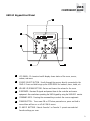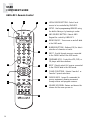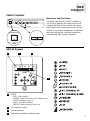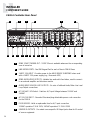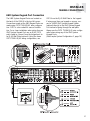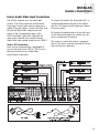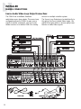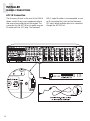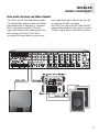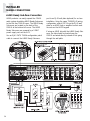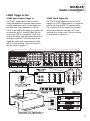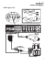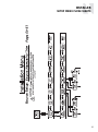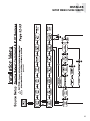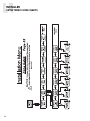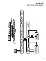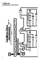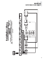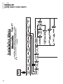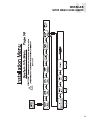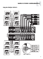
1
CAV6.6-S2 System
6-Zone, 6-Source
Audio/Video Controller Amplifier
INSTRUCTION MANUAL
IMPORTANT SAFEGUARDS
9. Heat - The appliance should be situated away from heat sources such
as radiators, heat registers, stoves, or other appliances (including
amplifiers) that produce heat.
10.Power Sources - The appliance should be connected to a power supply
only of the type described in the operating instructions or as marked on
the appliance.
WARNING: TO REDUCE THE RISK OF FIRE OR ELECTRIC SHOCK,
DO NOT EXPOSE THIS APPLIANCE TO RAIN OR MOISTURE.
11.Grounding or Polarization - Precaution should be taken so that the
grounding or polarization means of an appliance is not defeated.
CAUTION: TO REDUCE THE RISK OF ELECTRIC SHOCK, DO NOT
REMOVE COVER. NO USER - SERVICEABLE PARTS INSIDE.
REFER SERVICING TO QUALIFIED SERVICE PERSONNEL.
12.Power Cord Protection - Power supply cords should be routed so that
they are not likely to be walked on or pinched by items placed upon or
against them, paying particular attention to cords at plugs, receptacles,
and the point where they exit from the appliance.
The lightning flash with arrowhead symbol, within an equilateral
triangle, is intended to alert the user to the presence of uninsulated
“dangerous voltage” within the product’s enclosure that may be of
sufficient magnitude to constitute a risk of electric shock to persons.
The exclamation point within an equilateral triangle is intended to
alert the user to the presence of important operating and maintenance (servicing) instructions in the literature accompanying the
appliance.
POWER CORD NOTICE FOR INTERNATIONAL OPERATION
For 230V, 50Hz operation please select the power cord for your
area. Select the plug for your area at one end and a IEC320 connector at the other. It is not necessary to make any other
changes. If you have any questions please call Russound Inc. at
1-800-638-8055 or 603-659-5170
Safety Instructions:
1. Read Instructions - All the safety and operating instructions should be
read before the appliance is operated.
2. Retain Instructions - The safety and operating instructions should be
retained for future reference.
3. Heed Warnings - All warnings on the appliance in the operating instructions should be adhered to.
4. Follow Instructions - All operating and user instructions
should be followed.
5. Water and Moisture - The appliance should not be
used near water; for example, near a bathtub, washbowl, kitchen sink, laundry tub, in a wet basement,
or near a swimming pool.
6. Carts and Stands - The appliance should be used only
with a cart or stand that is recommended by the manufacturer. An
appliance and cart combination should be moved with care. Quick
stops, excessive force and uneven surfaces may cause the appliance
and cart combination to overturn.
7. Wall or ceiling Mounting - The appliance should be mounted to a wall
or ceiling only as recommended by the manufacturer.
8. Ventilation - The appliance should be situated so that its location or
position does not interfere with its proper ventilation. For example, the
appliance should not be situated on a bed, sofa, rug, or similar surface
that may block the ventilation openings, or placed in a built-in installation, such as a bookcase or cabinet that may impede the flow of air
through the ventilation openings.
2
13.Cleaning - The appliance should be cleaned only as recommended by
the manufacturer.
14.Non-use Periods - The power cord of the appliance should be
unplugged from the outlet when left unused for a long period of time.
15.Object and Liquid Entry - Care should be taken so that objects do not
fall and liquids are not spilled into the enclosure through the openings.
16.Damage Requiring Service - The appliance should be serviced by qualified service personnel when:
A. The power supply cord or the plug has been damaged; or
B. Objects have fallen, liquid has been spilled into the appliance; or
C. The appliance has been exposed to rain; or
D.The appliance does not appear to operate normally; or
E. The appliance has been dropped or the enclosure is damaged.
17.Servicing - The user should not attempt to service the appliance beyond
that described in the operating instructions. All other servicing should
be referred to qualified service personnel.
Precautions:
1. Power – WARNING: BEFORE TURNING ON THE POWER FOR THE
FIRST TIME, READ THE FOLLOWING SECTION CAREFULLY.
All models are designed for use with either AC120V, 60Hz or AC240,
50Hz voltages. The unit will autoswitch to either of these voltages
2. Do Not Touch The CAV6.6 With Wet Hands – Do not handle the CAV6.6
or power cord when your hands are wet or damp. If water or any other
liquid enters the CAV6.6 cabinet, take the CAV6.6 to a qualified service
person for inspection.
3. Location of CAV6.6 – Place the CAV6.6 in a well - ventilated location.
Take special care to provide plenty of ventilation on all sides of the
CAV6.6 especially when it is placed in an audio rack. If ventilation is
blocked, the CAV6.6 may overheat and malfunction. Do not expose the
CAV6.6 to direct sun light or heating units as the CAV6.6 internal components temperature may rise and shorten the life of the components.
Avoid damp and dusty places.
4. Care – From time to time you should wipe off the front and side panels
of the cabinet with a soft cloth. Do not use rough material, thinners,
alcohol or other chemical solvents or cloths since this may damage the
finish or remove the panel lettering.
TABLE OF CONTENTS
USER SECTION
Product Introduction ................................................................................................................6
Component Guide
CAV6.6 Controller.............................................................................................................7-8
UNO-S2 Keypad ..................................................................................................................9
UNO-LRC1 Remote Control ................................................................................................10
Operation
CAV6.6 Controller .............................................................................................................11
UNO-S2 Keypad............................................................................................................11-12
Setting Prefences
UNO-S2 User menu ...........................................................................................................13
INSTALLER SECTION
Getting Started
Unpacking ........................................................................................................................16
System Components .........................................................................................................16
Tools Needed....................................................................................................................16
System Installation Considerations......................................................................................16
Connection Tips ................................................................................................................16
Wiring Instructions
Keypad Wiring...................................................................................................................17
Speaker Wiring .................................................................................................................17
Component Guide
CAV6.6 Controller Front Panel .......................................................................................18-19
CAV6.6 Controller Rear Panel ........................................................................................20-21
UNO-S2 Keypad Front Panel...............................................................................................22
UNO-S2 Keypad Rear Panel ...............................................................................................23
UNO-S2 Keypad Installation
Keypad Location ...............................................................................................................24
Keypad Installation ............................................................................................................24
Keypad Connections..........................................................................................................25
IR Receiver Connection ......................................................................................................26
Making Connections
UNO-S2 Keypad Port Connection........................................................................................27
Programming Center Keypad Port Connection.....................................................................28
Source Audio/Video Input Connections ...............................................................................29
Source Audio/Video Loop Output Connection ......................................................................30
Speaker Connections ........................................................................................................31
3
TABLE OF CONTENTS
Accessory IR Connection ...................................................................................................32
Zone Audio/Video Outputs .................................................................................................33
A-BUS Ready Sub-zone Connection .....................................................................................34
12VDC Trigger In/Out
Home Theater Trigger In ................................................................................................35
50mA Trigger Out..........................................................................................................35
Page Trigger In/Out .......................................................................................................36
Page Audio/Video In .................................................................................................36-37
Zone Trigger Out ...........................................................................................................38
R-NET Link In/Out ..............................................................................................................39
RS-232 Interface ...............................................................................................................40
Initial Install Test................................................................................................................41
Programming
System Programming Overview .................................................................................42-43
Source Information Form................................................................................................44
Zone Information Form...................................................................................................45
Macro Editor Form ........................................................................................................46
Installation Menu...........................................................................................................47-58
Source Setup ...........................................................................................................48-53
Basic Setup ............................................................................................................48-49
Zone Setup ..............................................................................................................53-54
Controller Setup ............................................................................................................54
Power Management ..................................................................................................55-56
Learn IR........................................................................................................................57
Macro Editor ............................................................................................................57-58
System Info...................................................................................................................58
Setup Menu Flow Charts ...........................................................................................59-69
REFERENCE SECTION
Source Names List ...............................................................................................................71
Sample System Configurations
1 -Six Zones and Six Sources ........................................................................................72-73
2 - Integrate Multiple CAV6.6's ......................................................................................74-75
3 - Zone Expansion .......................................................................................................76-77
4 - A-BUS Ready Sub-zone Addition ................................................................................78-79
5 - Additional Amplification ............................................................................................80-81
6 - Home Theater .........................................................................................................82-83
IR Code List .....................................................................................................................84-86
Technical Specifications.........................................................................................................87
Warranty ..............................................................................................................................88
4
USER SECTION
Component Guides
Explains front panel features of the CAV6.6 controller,
UNO-S2 keypad, and UNO-LRC1 remote control.
Operation
Step-by-step outline of the system's normal operation,
plus a look at adjustable features available through the User Menu.
R
PW
SE
TV
TUP
CE
UR
L SOROL
CA
LO CONT
DVD
O
UN
3
VID
2
1
6
5
4
9
TER
EN
8
7
0
TE
MU
ST
LA
CH
EP
SLE
T
INPU
L
VO
EXIT
GUIDE
CT
SELE
U
MEN
O
INF
4
F2
F1
3
2
1
T
INPU
8
7
6
5
5
PRODUCT INTRODUCTION
Thank you for choosing the Russound® CAV6.6-S2 System to enhance your home with distributed
audio and video. This system’s state-of-the-art features and components blend seamlessly with your
unique lifestyle and preferences.
Besides distributing and controlling six A/V sources to six rooms (zones), your CAV6.6-S2 System
offers many features that increase your enjoyment of living. Here are several that you may find
particularly beneficial.
Favorites
The UNOTM-S2 keypad’s F1 and F2 buttons are preset favorites. These easy-to-set buttons make it
possible to hear your favorite radio station or watch your favorite satellite channel at just the
right volume in your room with just a button push. Want something new? Just re-save the Favorite
with a new choice.
Do Not Disturb
The Do Not Disturb mode prevents unwanted interruptions in your room and stops changes to your
selected A/V source. You may have a nursery or study that you want to keep quiet, or maybe you
are watching a DVD and don’t want it interrupted. Simply set the Do Not Disturb mode to “on” using
the User Menu, and be free from paging, Party Mode interaction and system-wide functions like “All
On” or “All Off.”
Party Mode
Ready to set the mood? In Party Mode, you just pick the source and the sound settings and hear the
music throughout all the rooms. The Master keypad simultaneously controls all the keypads in all the
rooms to effortlessly select or control the components. A great benefit of the Party Mode feature is
the ability to transfer the Master keypad mode to any keypad in the system. If the living room is the
center of the party, use that room’s keypad as Master. If the party moves to the sunroom and porch,
that room’s keypad can be set to Master instead.
Front (Aux) A/V In
This handy feature lets you easily hook up an additional temporary audio/video source through the
front of the controller. This way, your teenager can set up a game console when his friends come
over, and easily take it down without having to leave the games set up in the living room. Or your
family can watch the video camera playback of the holiday gathering while everyone is still there.
Here at Russound we are proud to continue providing innovative and intuitive A/V product solutions to
the world. When you link the industry-leading CAV6.6-S2 system with Russound’s commitment to its
products and customers, you have truly made – “the right connection.”
6
USER
COMPONENT GUIDE
CAV6.6 Controller-Front Panel
2
1
5
3
4
6
1
MAIN POWER SWITCH - Supplies power to the CAV6.6
2
REMOVABLE COVER LENS - Covers the connections on the front of the CAV6.6
3
ROOM LED ON/OFF INDICATORS - Indicates when a room is on (green) or off (red)
4
ROOM LABEL WINDOW - Holds the selected room Label (included)
5
AUX A/V LINE INPUTS - Supports connection of a seventh A/V source to the CAV6.6
6
AUX IR OUT PORT - Connects IR emitter for IR control of the Aux A/V source component
7
USER
COMPONENT GUIDE
CAV6.6 Controller-Front Panel
Front A/V Aux Connections
The Aux Input is located to the right of the power
switch on the front panel. Connect the Left,
Right, and Video Input Connectors to the source
component using quality RCA signal cables.
8
The Aux IR jack adjacent to the line input
accepts an IR Emitter with a 1/8” plug (e.g.,
Russound 845.1 IR emitter). The emitter’s other
end attaches to the IR window of the component
to control the auxiliary source.
USER
COMPONENT GUIDE
UNO-S2 Keypad-Front Panel
1
7
2
6
3
5
4
1
LCD PANEL - 12-character backlit display shows status of the room, source,
volume, and more
2
SOURCE SELECT BUTTON - Scrolls through the sources directly connected to the
CAV6.6. Press and hold brings up the USER MENU for loudness, bass, treble, etc.
3
VOLUME UP/DOWN BUTTONS - Raises and lowers the volume for the room
4
IR RECEIVER - Receives IR signals and passes them to the controller and source
equipment. Also used when operating the UNO Keypad by using the UNO-LRC1 remote
5
COMMAND KEYS - Pressing the command keys controls the source equipment
6
POWER BUTTON - Turns room ON or OFF when pressed once, press and hold a
second time will turn on or off all CAV6.6 rooms
7
F1 AND F2 BUTTONS - Selects Favorite 1 or Favorite 2 - preset user-selected
favorite settings per room
9
USER
COMPONENT GUIDE
UNO-LRC1 Remote Control
2
3
4
1
LOCAL DEVICE BUTTONS - Select local
source to be controlled by UNO-LRC1.
2
SETUP - Use for programming UNO-LRC1 using
the built-in library or by learning-in codes.
3
UNO SOURCE BUTTON - Selects UNO
Keypad for control by UNO-LRC1.
4
ROOM ON/OFF - Turns room on and off while
in the UNO mode.
5
NUMBER BUTTONS - Buttons (0-9) for direct
selection of channels or tracks.
6
INPUT - Scrolls through sources connected
to the CAV6.6 while in the UNO mode.
7
COMMAND KEYS - Control the VCR, DVD, or
CD player with these buttons.
8
INPUT - Directly select A/V sources connected
to the CAV6.6 while in the UNO mode.
9
F1 AND F2 BUTTONS - Selects Favorite 1 or
Favorite 2 preset selections.
1
5
11
6
10
10
CURSOR KEYS - Issues IR commands for
source equipment, allowing movement
through menus and program screens.
11
VOLUME UP/DOWN - Raises and lowers the
volume for the room you are in.
7
9
8
10
USER
OPERATION
CAV6.6 Controller
Main Power and Zone Status
The power switch for the CAV6.6 controller is
"on" in the up position. Any active room is indicated on the front of the controller by a green
backlit label, which shows red when the room is
inactive. In most basic installations, all functions
and room settings are controlled through the
corresponding UNO Systems Keypads.
UNO-S2 Keypad
1
2
3
4
1
MODE:
“DND”- Do Not Disturb
“SHARED”- Same source selected in multiple rooms
“SYS-ON”- Indicates system on
“PARTY”- Party Mode enabled
“MASTER”- Master Keypad in Party Mode
2
12-character display
3
Volume Indicator
4
Indicates the middle of setting range
11
USER
NORMAL OPERATION
UNO-S2 Keypad
Zone On/Off
is also used to enter the User Menu with a
Press and release
to turn on the UNO
System Keypad. This also turns on the corre-
press and hold action. (See next page for User
Menu)
sponding CAV6.6’s room, and any presets previously assigned will be activated, including settings for bass, volume, last source selected,
etc. Press and release
to turn off the UNO
Volume Up/Down Buttons
The room’s audio output is adjusted using
.
F1 and F2 Buttons
System Keypad. This will also put the corresponding
The
CAV6.6’s room into a standby state.
sets. These presets can be selected at any time
System All On/Off
to recall source selection, volume, and favorite
An “All On” command is issued by pressing
channel, disk, etc. To store a favorite preset: first,
and holding for 3 seconds, after an initial room
adjust the room settings and select a source to be
has been turned on. An “All Off” command can
stored. Next, press and hold the desired
be issued to all rooms by pressing and holding
after the room has been turned off.
System On Indicator
When the room is off, but the system is on in
another room,
is illuminated by a green
backlight and the "SYS ON" icon remains visible.
and
buttons are user favorite pre-
or
button until SAVED is displayed on the LCD
panel. Now a press and release of the button will
recall the favorite preset. To set a favorite numbered disk or channel, use
or
to select a
disk or channel (e.g., channel 45). Wait for the
keypad to show the source name, then press
and hold the F1 or F2 within 15 seconds of set-
Source Select Button
ting the numeric selection to save the setting.
scrolls through the six A/V source inputs
and the Aux source. To change sources, press
and release
. As the sources are sequentially
selected, each source's name appears on the
keypad LCD panel. When a source is selected in
more than one room, the “SHARED” icon will
appear on all UNO Keypads using that source.
12
Command Keys
The command keys allow control of the selected
source at the UNO Keypad. The command keys are
activated with a press and release, or press and
hold to access secondary functions.
USER
USER MENU SETTINGS
UNO-S2 User Menu Operation
The User Menu allows the user to adjust the
audio properties and control functions of a particular room.
The following keys are used to navigate and
make changes while using the User Menu:
To enter the User Menu, press and hold
during normal operation. To exit the User Menu,
press and release
.
Adjust feature setting (decrement).
Go to next feature.
Go to previous feature.
View current feature setting.
The following features make up the User Menu:
TREBLE
LOUDNESS
BALANCE
TURN ON VOL
BG COLOR
DO NOT
DSTRB
PARTY MODE
Do Not Disturb means do not disturb this room
or selected source. This stops pages from
being sent to this room, stops an “All Off," "All
On" or Party Mode command from affecting this
room.
When another UNO Systems Keypad selects the
same source, a DND icon will appear alerting
the user the source is in Do Not Disturb mode.
8. PARTY MODE - Master (Enable) or Off (Disable)
Adjust feature setting (increment).
BASS
7. DO NOT DSTRB - On or Off (default)
FRONT A/V IN
Feature and Setting:
1. BASS
-10 < Bass:Flat > +10
2. TREBLE
-10 < Treble:Flat > +10
3. LOUDNESS (more bass, fuller sound)
On or Off
4. BALANCE
Left -10 < Center > Right +10
5. TURN ON VOL (default room volume level)
0 to 100
6. BG COLOR (keypad background light)
Amber or Green or Off
When in “PARTY MODE” the system is primarily
controlled by a “MASTER” keypad. Party Mode
links all rooms to the same source which is
selected by the Master Keypad room. Any keypad in the system can become a Master keypad
(if enabled) but only one Master Keypad may
exist at a time in Party Mode. Selecting Master
keypad mode from another keypad will transfer
Master keypad control to that room and release
it from the first. When the source selected in the
Master keypad room is changed then the source
for all rooms changes as well.
Volume level changes at the Master Keypad will
be reflected in all rooms in Party Mode. NonMaster zones in Party Mode can temporarily override Master Keypad volume level adjustments for
their particular room preference. F1 and F2
favorite presets selected from the Master Keypad
will be enabled in all rooms in Party Mode. Master
Keypad will not change Bass, Treble, or Loudness
adjustments for any other rooms other than the
Master Keypad room. Every other keypad will still
operate its respective bass, treble, balance and
loudness adjustments for that room.
9. FRONT (AUX) A/V IN - Enabled or Disabled
Allows the system to select a seventh source option
through the controller's front panel AUX connection
for use with camcorders, game consoles, etc.
13
INSTALLER SECTION
Getting Started
Includes an installation overview, including tools needed and wiring instructions.
Component Guides
Reviews front and back panel features of the CAV6.6 controller and the UNO-S2 keypad.
Keypad Installation
Explains UNO-S2 keypad installation and wiring.
Making Connections
Details front and back panel connections of the controller and the keypad.
System Installation Overview
Outlines the programming planning process, and includes information forms to complete prior to
programming.
Installation Menu
Explains the programming menus that set up controller, keypad, source, and zone operations.
Setup Menu Flow Charts
Presents the programming menus in a graphical flow chart format.
14
INSTALLER
CAUTION
Do not connect the controller's main power feed until all other connections have been
made and verified. Live connection or removal of the keypad wiring or other wiring
when the system is powered can cause communication problems in the network.
Double-check terminations during each phase of the installation to prevent accidental
damage. Incorrect wiring is the number one cause for non-warranty product damage.
15
INSTALLER
GETTING STARTED
Unpacking the System Components
• Keep the original carton and packing materials
for future shipment or storage.
• Check for any visible signs of damage. If
you encounter any concealed damage, consult your Russound dealer before proceeding
to install the unit.
• Retain the sales receipt as it establishes the
duration of the limited warranty and provides
information for insurance purposes.
CAV6.6-S2 System Components:
• 1 (one) CAV6.6 Controller/Amplifier
• 6 (six) UNO-S2 System Control Keypads
• 1 (one) UNO-LRC1 Learning/Preprogrammed
Remote Control
• 6 (six) 845.1 Micro Emitters
Tools needed for installation:
• Drill with a 1/2” x 6” drill bit
• Keyhole saw
• Flat head screwdriver (medium size)
• Phillips Screwdriver (cordless recommended)
• 110 punchdown tool (included)
• Modular RJ-45 crimper and connectors
• Pair of diagonal cutters or wire strippers
• Stud finder
• Steel wire fish tape
• Cable staples
• Double-gang electrical work boxes
System Installation Considerations
There are several factors to consider before
installing the Russound CAV6.6-S2 system:
16
• What are the intended listening zones, and
what zones require audio and video distribution
or audio only?
• Are A-BUS® sub-zones needed? A-BUS subzones are only available for zones 1 - 4. The AKP2 amplified keypad can provide direct source
selection for only the first four sources when in
‘Multi’ source mode.
• What system options and accessories might
be required for features such as paging, local
sources, etc.?
• From where in each zone will the user prefer
to control the system? Where will the keypads
be located? Where will the speakers be located?
• Where will the source equipment be located?
The CAV6.6 must have proper ventilation above
and below for air circulation and heat dissipation.
A rack-mount location may require fans and vents.
Connection Tips
• It is recommended that the CAV6.6 and the
source equipment be plugged into a dedicated
20-amp circuit with an isolated ground. A power
line conditioner can reduce interference problems caused by noise found in some electrical
systems.
• Disconnect all live power cords before making
connections to the controller.
• Verify that all connections and polarity are
correct.
• Keep all power cords away from all signal
cables to prevent humming from induced noise.
• Choose reliable signal cables/patch cords.
• Label all wires with room location at both ends
of the wire.
INSTALLER
WIRING INSTRUCTIONS
RJ-45 Connections
The CAT-5 T568A wiring standard shown on the right is used
for the RJ-45 terminations.
Keypad Wiring
For the UNO-S2 keypad, the following connections are used to terminate the CAT-5 wire to the
110 punchdown on the keypad:
CAT-5 WIRE COLOR
TYPE
Brown . . . . . . . . . . . . . . . . . . . +12V
Brown/White . . . . . . . . . . . . . . +12V
Green . . . . . . . . . . . . . . . . . . Ground
Green/White . . . . . . . . . . . . Status In
Orange . . . . . . . . . . . . . . . . . Ground
Orange/White . . . . . . . . . . . . . IR Out
Blue . . . . . . . . . . . . . . . . . . . COM A
Blue/White . . . . . . . . . . . . . . COM B
• To determine the amount of CAT 5 wire
required for the system installation, first
decide how many keypads will be used, then
determine the distance between each intended keypad location to the intended CAV6.6
location. The maximum recommended wire
run length is 250 feet for each UNO-S2
Keypad.
• Make sure that the entire wire path
between keypads and CAV6.6 is clear and
not obstructed by a floor ceiling joist, or
masonry wall which can’t be drilled through.
• Confirm ahead of time that you can drill an
outlet hole easily and in an unobtrusive spot
to connect wires with the CAV6.6.
• Label wires with keypad and room location.
This simplifies CAV6.6 hook-up once the keypads and speakers are installed.
• If you plan to use an additional IR receiver
with an UNO-S2 keypad, first determine the
location of the IR receiver, then measure the
distance from the intended location to the
UNO-S2 keypad location. Incorporating
optional IR receivers will require additional
wire. Consult the selected IR receiver
model’s manual for the specific wire needs.
Speaker Wiring
• Standard 16-gauge 4-conductor stranded
speaker wire can be run up to to 125 feet;
14-gauge wire can be run up to 250 feet.
• When running wire, pay particular attention
to the following areas:
• Avoid locations concealing pipes, heating
ducts and AC wiring in the general vicinity.
• Avoid running wires close to house electrical wiring for any distance. If you have to run
them parallel, make sure to space the wires
at least two feet from the AC line.
17
INSTALLER
COMPONENT GUIDE
CAV6.6 Controller-Front Panel
1
2
3
4
5
6
11
8
7
9
10
18
INSTALLER
COMPONENT GUIDE
CAV6.6 Controller-Front Panel
1
PROGRAM SELECTOR COVER - Protects the Program Selector Switch
2
KEYPAD PROGRAMMING PORT - Accepts an RJ-45 terminated UNO keypad to
program certain features of the CAV6.6
3
FRONT/REAR RS-232 SWITCH - Selects front or rear RS-232 connection for optional
PC connection during programming
4
RS-232 INTERFACE - The RS-232 Interface on the front and on the rear, allows the
zones to be controlled by PC or other devices that have an RS-232 Interface.
The RS-232 Interface also allows for software updates
5
IR CONFIRMATION LED - IR Learning and preprogrammed IR output confirmation LED.
6
IR RECEIVER - Receives IR signal when learning IR codes into the CAV6.6
7
ZONE LABEL - Selectable backlit labels identify active zones
8
OS PROGRAM SELECTOR SWITCH - Selects between Main and Aux Micro-controller IC
when updating the CAV6.6 OS software.
9
MAIN LED - IIlluminates when the Main Micro-Controller IC is selected to be
programmed
10
AUX LED - Illuminates when the AUX IC is selected to be programmed
11
RESET BUTTON - Resets the CAV6.6 when OS updates are completed
19
INSTALLER
COMPONENT GUIDE
CAV6.6 Controller-Rear Panel
1
21
20
2
20
19
3
18
17
4
16
15
5
14
13
12
11
6
10
9
8
7
1
ZONE 12VDC TRIGGER OUT - 12VDC 50ma is available whenever the corresponding
zone is turned on
2
UNO KEYPAD PORTS - One UNO Keypad Port for each of the six CAV6.6 Zones
3
24VDC 2.5A INPUT - Provides power to the A-BUS READY SUB-ZONES when used
with a 24VDC 2.5A power supply (e.g., Russound A-PS)
4
ZONE AUDIO/VIDEO OUTPUTS - Variable line audio with fixed video, used to connect
to an external amplifier and television monitor
5
AUDIO/VIDEO SOURCE LOOP OUTPUTS - Six sets of buffered Audio/Video Line Level
Loop Output connections
6
AC 240V-AC 110V Switch - Switches A/C input Voltage between 110VAC and
240VAC
7
AC 120/240 INPUT - Grounded 3-terminal plug detachable power cord connection
for the CAV6.6
8
FUSE HOLDER - Holds a replaceable fuse for A/C input connection
110VAC operation-F 3A H 250V, 240VAC operation-F 1.25A H 250V
9
SOURCE IR OUTPUTS - Six routed source-specific IR Output jacks allow for IR control
of source equipment
INSTALLER
COMPONENT GUIDE
CAV6.6 Controller-Rear Panel
10
SPEAKER OUTPUTS - Connect 8 Ohm speakers for each zone by using detachable
color-coded modular snap connectors
11
AUDIO/VIDEO INPUTS - Six sets of Audio/Video Line Level input connections for
CAV6.6 source components
12
ACC IR OUTPUT - ACC IR Output jack will pass all IR signals from all keypads
13
PAGE LINE LEVEL AUDIO GAIN CONTROL - Adjusts the Line Level Audio Page Input
14
PAGE A/V INPUTS - RCA jacks allow for one Audio/Video Page Input. Signal sensing
is used on Page Audio In to initiate a page
15
PAGE 12VDC TRIGGER OUT - Page Trigger Out supplies 12VDC whenever 12VDC is
applied to the Page 12VDC Trigger In
16
PAGE 12VDC TRIGGER IN - Applying 12VDC to the Page 12VDC Trigger In jack will
activate Audio/Video Page for assigned CAV6.6 Zones and initiate a page (overrides
signal sense)
17
HOME THEATER 12VDC TRIGGER IN - 12VDC input jack notifies the CAV6.6 that
additional A/V components are active, e.g., home theater equipment
18
12VDC TRIGGER OUT - 12VDC 50ma Trigger Out turns on when any zone is on
19
A-BUS READY SUB-ZONES - A-BUS Amplified Control Modules and Hubs can be added
for additional sub-zones of audio (Zones 1 to 4 only)
20
R-NET LINK IN AND LINK OUT - Links multiple CAV6.6’s, also links future Russound
components that are R-NET compatible
21
RS-232 INTERFACE - The RS-232 Interface on the rear and on the front, allows the
zones to be controlled by PC or other devices that have an RS-232 Interface. The
RS-232 Interface also allows for software updates and programming
21
INSTALLER
COMPONENT GUIDE
UNO-S2 Keypad-Front Panel
1
DATA
RS-232
DATA
GND
N/C
+12VDC
2
22
1
SETUP BUTTON - Activates Installer Setup Mode for the UNO-S2 keypad
2
OS UPDATE PORT - Port used for UNO keypad OS software updates
INSTALLER
COMPONENT GUIDE
UNO-S2 Keypad-Rear Panel
2
3
1
4
1
EXTERNAL IR RECEIVER IN CONNECTOR - Connection for an external IR Receiver.
2
OS UPDATE JUMPER - Selects “Run” or “OS Update” mode.
3
RESET BUTTON - Reset whenever changing from RUN to OS update
4
110 PUNCHDOWN CONNECTOR - Termination for CAT-5 connection between the
UNO-S2 Keypad and the CAV6.6 controller.
23
INSTALLER
UNO-S2 KEYPAD-INSTALLATION
Keypad Location
The best infrared remote performance is achieved
with the keypad away from any direct sunlight,
plasma TV, and low voltage lighting controls. Also
consider convenience when choosing a location.
Choose a place that is easily seen from the position where a person is most likely to be located.
Check whether or not you can route the wire to
the location you have chosen.
Keypad Installation
To install a double-gang keypad, you will need to
use a UL/CSA approved plastic double-gang
electrical box.
Route CAT-5 wire to the junction box from the
CAV6.6.
Use the supplied 110 punchdown tool to connect each wire to its corresponding color
labeled on the punchdown terminal.
Ensure jumper settings on keypads are in the
run positions.
Mount the keypad in the electrical box and
attach the cover plate. Repeat the steps until all
keypads are installed.
Plastic Double-Gang
Electrical Box
UNO-S2
Back Plate
Screw
Screwless
Cover Plate
Screw
24
INSTALLER
UNO-S2 KEYPAD-INSTALLATION
UNO-S2 Keypad Connections
CAT-5 Connection
The UNO-S2 Keypad uses a 110-punchdown
terminal to provide a simple installation and
strong connection for CAT-5 cable’s eight conductors. Punchdown terminals require the use of
a punchdown tool which has been provided with
the keypad kit. Attach the CAT-5 cable to the
110-punchdown terminal on the UNO-S2 Keypad
as shown, matching the conductor colors to the
connection color guide. The keypad will not
operate properly if the terminations deviate from
the required connection order.
Caution:
Take care when using an impact 110 punchdown
tool, as this may overspread the contact points.
Use of the impact tool may propel stray bits of wire
and jacket into the keypad’s chassis and possibly
cause a short in the circuitry. Gently shake or blow
air through the keypad chassis to remove stray wire
before the keypad is installed into the junction box.
OS Update Port
The OS Update Port is is used to update the
UNO-S2 Keypad operating system software in
the future. When an update is released, it will be
available online through the Document Center at
www.russound.com. Look for the Technical
Documents under Multi-source/Multi-room products. The programming cable is available from
Russound, Part #2500-120633.
Jumper Setting
The jumper settings on the back of the UNO-S2
Keypad can be set for “Run” and “OS Update.” The
jumper setting must be in the “Run” position before
the keypad is mounted into the junction box, and
must remain set in “Run” to operate the keypad.
The jumper will be set to “OS Update” only while
updating the keypad’s operating systems.
Punchdown Tool
Jumper Setting (back of keypad)
Punchdown Tool
CAT-5 Connections (back of keypad)
OS Update Port (front of keypad)
25
INSTALLER
UNO-S2 KEYPAD-INSTALLATION
IR Receiver Connection
The UNO-S2 keypad has an External IR Receiver
In terminal for connecting an external IR receiver
such as the Russound 858, SaphIR Eye, or
SaphIR Phantom. Use 2 twisted pair wire with
one pair connecting GND (GROUND) and IR (SIGNAL) and the other pair connecting ST (STATUS)
and V+ (+12VDC). If the wire has a shield, connect it to ground at the UNO-S2 only.
Back of
Russound 858
Back of
UNO-S2
26
INSTALLER
MAKING CONNECTIONS
UNO System Keypad Port Connection
The UNO System Keypad Ports are located on
the back of the CAV6.6 in the top left corner.
Connections made at the UNO Keypad Ports are
made using CAT-5 T568A RJ-45 wire configuration. CAT-5 is color-coded for ease of installation. For a clean installation when wiring from an
UNO System Keypad Port use an RJ-45 CAT-5
patch cable to connect from the keypad port to
an RJ-45 Wall Plate (optional). Using the same
CAT-5 T568A RJ-45 wiring configuration, use
CAT-5 from the RJ-45 Wall Plate to the keypad.
If using more than one keypad on a zone, connect a SA-ZX3 UNO System Keypad Splitter
(optional) directly to the UNO System Keypad
Port instead of going through the wall plate.
Always use the CAT-5 T568A RJ-45 wire configuration when wiring any of the UNO System
Keypad Ports.
(See Sample System Configuration 3, page 76)
27
INSTALLER
MAKING CONNECTIONS
Programming Center Keypad Port Connection
The CAV6.6 can be programmed via keypad connection using CAT-5 and the T568A RJ-45 wire configuration. An UNO-S2 Keypad can be attached to the controller at the Programming Center Keypad
Port Connection.
28
INSTALLER
MAKING CONNECTIONS
Source Audio/Video Input Connections
The CAV6.6 supports up to six audio/video
sources. The Source Inputs are located at the
back panel. Connect each source output using
quality RCA signal cables. Connect the Video, and
the Left and Right Audio outputs from each
source to the corresponding inputs on the
CAV6.6 controller. Label each cable with the
name of the selected source and the Source
Audio/Video input number located on the CAV6.6.
Source IR Connections
Each source component has a designated IR
port on the back of the CAV6.6. This IR port is
directly below the Source Audio/Video
Input/Output Connections.
1. Using an IR emitter (the Russound 845.1 is
recommended) attach the end of the emitter
with the 1/8” plug to the IR emitter port below
the source input.
2. Remove the adhesive back at the other end
of the emitter and attach the emitter over the
source component’s IR window.
3. In order to control this source component
with IR, the source must be selected at the keypad receiving the command.
29
INSTALLER
MAKING CONNECTIONS
Source Audio/Video Loop Output Connections
The CAV6.6 has six buffered, fixed-level
audio/video source loop outputs. This source loop
configuration allows the CAV6.6 to pass source
signals to another component, such as a home
theater receiver or to another CAV6.6 for sharing
30
sources in a multiple controller system.
The Source Loop Outputs are located directly to
the right of the Source Audio/Video Inputs. Use
quality RCA signal cables to ensure quality transference of Audio/Video signals.
INSTALLER
MAKING CONNECTIONS
Speaker Connections
The speakers are connected to the CAV6.6
using modular snap speaker connectors. Each
of these color coded connectors is designated
for the speaker set of a particular amplified
zone. To avoid confusion, connect one zone
speaker set at a time starting with Zone 1, taking care to keep zone and speaker wire identities straight. Note: An 8 Ohm minimum speaker
is required for each amplified output.
WHITE -- L+ (left channel positive)
GREEN -- L- (left channel negative)
BLACK -- R- (right channel negative)
RED -- R+ (right channel positive)
1. Pull the speaker wire conductors apart so
they’re separated for the first two inches from
their ends.
Lift the black lever for each connection until it
locks open and insert the proper speaker
wire, matching channel and polarity for all
four wires. Snap the lever down. Insert the
modular connector into its designated output
on the back of the CAV6.6.
2. Using a wire stripper, remove 1/4 inch of
insulation from each conductor. Twist the
strands in each conductor into tight spirals.
4. Complete the same steps for the remaining
zones. Label each set of speaker wires with
the zone and location.
3. Remove the modular four-color connector for
Zone 1. The color code is as follows:
31
INSTALLER
MAKING CONNECTIONS
ACC IR Connection
The Accessory IR jack on the rear of the CAV6.6
allows control of any source equipment without
that source being selected on the keypad. The
connection for the ACC IR jack is made using an
IR emitter with the 1/8’’ plug. The Russound
32
845.1 single IR emitter is recommended, or use
an IR connecting block such as the Russound
857 which allows multiple units to be controlled
through the ACC IR Port.
INSTALLER
MAKING CONNECTIONS
Zone Audio (to Amp) and Video Outputs
The CAV6.6 has six Zone Audio/Video outputs.
The Variable Audio outputs can be used if additional amplification is desired (e.g., Russound
DPA-1.2 two-channel amplifier). The Zone
Audio/Video Outputs are located slightly to the
left of center on the rear of the CAV6.6.
Use quality RCA signal cables to ensure a con-
stant quality Audio signal. Video for the zone will
be routed via the Video connection.
Use RG59 Coax Cable or an RG6 Cable with 95%
copper braided shield and solid copper core up to
150 feet long for video connections to monitors.
33
INSTALLER
MAKING CONNECTIONS
A-BUS Ready Sub-Zone Connection
A-BUS products can easily expand the CAV6.6
audio system by adding A-BUS Ready Sub-zones
to the first four CAV6.6 zones. The A-BUS Ready
Sub-zones are located on the back of the
CAV6.6 at the bottom left corner. The A-BUS
Ready Sub-zones are powered by a 24VDC
power supply such as the A-PS.
Use an RJ-45 CAT-5 T568A configuration patch
cable to connect the A-BUS Ready Sub-zone
port to an RJ-45 wall plate (optional) for a clean
installation. Using the same T568A RJ-45 wiring
configuration, attach CAT-5 from the RJ-45 wall
plate to an A-BUS hub or amplified control module such as the A-KP2 keypad.
If using an A-BUS hub with the A-BUS Ready Subzone, the hub should be located near the
CAV6.6 and wired directly instead of first going
through the wall plate.
V+ V- L+ L- R+ R- IR ST
V+ V- L+ L- R+ R- IR ST
34
INSTALLER
MAKING CONNECTIONS
12VDC Trigger In/Out
12VDC Home Theater Trigger In
This 12VDC Trigger input is used to control
Power Management of the audio/video sources
possibly being shared with a home theater system. When the source equipment is off and
12VDC is provided to the trigger, the sources will
be turned on until it is removed. When the last
zone on the CAV6.6 is turned off, 12VDC presence to the trigger input will prevent the sources
from being turned off. The connections for the
trigger are made using a two-conductor cable
with 1/8” male mini-plug. The tip is positive (+)
and the sleeve is negative (-).
12VDC 50mA Trigger Out
The 12VDC 50mA trigger out can be used to
engage any 12VDC trigger device or component
such as the Russound ACT-1 triggered outlet.
The connections for the trigger out are made
using a two-conductor cable with 1/8” male
mini-plug jacks at each end. The tip is positive
(+) and sleeve is negative (-).
35
INSTALLER
MAKING CONNECTIONS
12VDC Trigger In/Out
12VDC Page Trigger In
When 12VDC is applied to the Page Trigger In,
the system will page audio that is connected to
the Page Audio Input and interrupt the video outputs with the page video signal. The Page Trigger
In is located in the Page connection area of the
CAV6.6 Controller. The connections for the trigger are made using a two-conductor cable with
1/8” male mini-plug jacks. The tip is positive (+)
and sleeve is negative (-). This allows for the connection of an external paging or muting device
such as the Russound DIM-1 Doorbell Interface
Module. The CAV6.6 can be programmed to
mute audio and video for one or all zones as preferred when the 12VDC is applied.
12VDC Page Trigger Out
Page Trigger Out 12VDC output is available
under several programmable situations, such as
for triggering an external amplifier, muting
device or other paging component dependent
on the Page Trigger In 12VDC. The connections
36
for the output are made using a two-conductor
cable with 1/8” male mini-plug jacks at each
end. The tip is positive (+) and sleeve is negative (-). The default setting for the Page Trigger
Out provides 12VDC whenever 12VDC is applied
to the Page Trigger In.
In some cases noise or interference may be
generated by external devices that are connected
to the 12 volt trigger outputs of the CAV. It may
be necessary to use a ferrite bead to reduce
this interference. Two to three turns of the connecting cable through the bead may be needed.
Page Audio/Video In
The Page Audio/Video Inputs accept line level
audio/video signals. The paging inputs interface
with the page output of a telephone, camera, or
other peripheral device. Connect the audio/video
signals using quality RCA cables.
INSTALLER
MAKING CONNECTIONS
12VDC Trigger In/Out
37
INSTALLER
MAKING CONNECTIONS
12VDC Trigger In/Out
Zone 12VDC Trigger Outputs
Zone 12VDC Triggers are located directly under
the UNO Keypad Ports. The 12VDC Trigger is
engaged when the corresponding zone is turned
on and disengaged when the zone is turned off.
The trigger can be used to engage any 12VDC
trigger device or component such as the
38
Russound DPA-1.2 amplifier. The connections for
the trigger outputs are made using a two-conductor cable with 1/8” male mini-plug jacks at
each end. The tip is positive (+) and sleeve is
negative (-).
INSTALLER
MAKING CONNECTIONS
R-NET Link In and Link Out
The R-NET Link In and Link Out is used to connect two or more CAV6.6 controllers. The connection is made using a CAT-5 patch cable from
the Link Out of the master CAV6.6 and into the
Link In of the next CAV6.6. Along with R-NET
data signals, the R-NET Link In and Link Out jack
passes the six source IR signals. These are only
for source-specific IR remote repeating, not
codes initiated from the controller’s internal IR
library. The CAT-5 patch cable should not
exceed 18 inches in length to avoid potential
cross-talk between the source-specific IR repeating signal lines.
Note: If two or more CAV6.6 controllers will be
connected using the R-NET Link In and Link Out
ports, each controller must have a unique
Controller ID (see Controller Setup - Flow
Chart on page 65) prior to being connected
through the R-NET ports. The Controller ID
assignment must be performed during the
Controller Setup section of the Installation menu.
The R-NET Link In and Link Out is also used to
connect the CAV6.6 to other Russound products
with R-NET.
39
INSTALLER
MAKING CONNECTIONS
RS-232 Interface
The CAV6.6 supports RS-232 communication with various third party automation systems or PC for
programming of the controller. Select the appropriate RS-232 port to update CAV6.6 OS software
(see Component Guides-Front Panel).The two RS-232 com ports are located on the front and the
back of the CAV6.6 and use a DB-9 cable connection. For RS-232 protocol and the backup PC application, see the Document Center at www.russound.com. Look for the Technical Documents under
Multi-source/Multi-room products.
40
INSTALLER
INITIAL INSTALL TEST
Before proceeding to the system programming section, it’s important to conduct an initial test to
determine that the hardware components are working properly.
1. Connect the speaker wires from Zone #1 to the CAV6.6 Zone #1 speaker output connectors.
2. Connect an UNO-S2 keypad to Keypad Port #1 on the rear of the CAV6.6.
3. Connect a source to the Source #1 Input on the CAV6.6 using RCA A/V patch cables.
4. Plug a supplied 845.1 IR emitter into the Source #1 IR Output Jack and adhere the emitter end
to the source equipment’s IR window.
5. Plug in the main power cords for the CAV6.6 and the source.
6. Turn on the main power switch on the CAV6.6 and the source.
7. Manually command the source to provide audio or use the source remote control.
8. Press the power button on the UNO-S2 keypad and select Source #1.
Congratulations – you should now hear the source through the speakers in Zone #1. Now that you
have confirmed the hardware operation, you can proceed to System Programming to set up keypad
source control.
If there is no sound, follow these diagnostic steps:
1. Check the source to see that it is operating properly.
2. Check the RCA A/V cable connections from the source to the Source #1 Input on the CAV6.6.
3. Check the speaker connections and verify that they are correct and are connected to the
Zone #1 speaker outputs.
4. Check to see that the keypad is connected to the Zone #1 Keypad Port and verify the CAT-5 is
properly terminated at both ends.
If none of these steps produce successful results, call Russound Tech Support for further assistance.
41
INSTALLER
SYSTEM PROGRAMMING OVERVIEW
This manual includes items that are designed to assist in the programming process.
Sample Configurations
A series of sample configurations are provided (pages 72-83) to showcase a variety of system
designs and component options.
Forms
Three blank reproducible forms (pages 44-46) are included as planning tools when determining
sources, settings and zone preferences. The Source and Zone Information forms and the Macro
Editor form should be completed before programming and referred to during the installation menu
process. This speeds up programming time and reduces missed or incorrect entries. These forms
also serve as system reference documents if future troubleshooting is needed.
IR Device Codes
This list of command type IR device codes (pages 84-86) reflects the built-in IR codes in the CAV6.6
library. During programming, these codes will be entered for each source at the “Device Code”
prompt. If a code is not listed for a source, the Learn IR procedure is available to learn in and centrally store IR codes.
Source Names
A list of assignable Source Names (page 71) is provided for advance selection and source form completion before programming.
Flow Charts
Installation Menu flow charts (pages 59-69) provide a graphical representation of the programming
process.
Installation Menu
The Installation Menu (pages 47-58) provides the step-by-step complete programming procedure for
the keypad and the controller.
Although you can begin programming at any point within the Installation Menu, the following sequence
is recommended for initial installations, as it progresses from the most basic requirements to the
more advanced features.
1. Controller Setup (CTRLR SETUP) (page 54)
This procedure sets the controller ID number within the system. This number must be manually set
when multiple CAV6.6’s are linked through R-NET within one system. This procedure is not necessary
for systems with only one CAV6.6.
2. Number of Sources (# of Sources/SOURCE SETUP) (page 53)
This procedure sets the number of sources used in the system. This prevents the user from selecting
a source input that is not used.
3. Basic Setup (SOURCE SETUP) (page 48)
This procedure is mandatory to set up each source for keypad source control and is the cornerstone
of the programming process.
42
INSTALLER
SYSTEM PROGRAMMING OVERVIEW
4. Learn IR (page 57)
This procedure is used when the source-specific IR code is not found in the built-in IR code library.
This allows IR commands to be learned into the system and centrally stored.
5. Macro Editor (page 57)
This procedure compiles multiple IR codes to be initiated by a single button press. One macro can
have up to 10 commands, including other macros, and up to 132 macros can be entered.
6. Source Volume Trim (SOURCE SETUP) (page 51)
This procedure matches audio output signals for all sources for seamless switching.
7. Numeric IR (SOURCE SETUP) (page 51)
This procedure sets up control of a source that supports direct numeric commands.
8. Key Configuration (SOURCE SETUP) (page 49)
This procedure customizes individual key functions on a per-zone basis for source control.
9. Power Management (page 55)
This function incorporates IR macro commands to automatically control the power state of the sources
when the system is in use or when a home theater is sharing sources. This advanced feature uses audio
signal monitoring to confirm source power, which provides the user with worry-free operation.
10. Zone Volume Trim (ZONE SETUP) (page 54)
This procedure limits the maximum volume allowed in a zone, regardless of keypad volume adjustment.
11. System On Enable (SYSON ENABLE/ZONE SETUP) (page 54)
This feature allows a zone to join or opt out of an “all on” command.
12. Party Enable (ZONE SETUP) (page 54)
This feature allows a zone to join or opt out of Party Mode participation.
13. Master Enable (ZONE SETUP) (page 54)
This feature allows a zone the option of becoming a Master keypad in Party Mode.
14. Page Enable (ZONE SETUP) (page 54)
This feature allows a zone to hear or to block paging.
15. Page Volume (ZONE SETUP) (page 54)
This feature allows adjustment of the paging volume in a zone.
43
INSTALLER
SETUP FORMS
44
INSTALLER
SETUP FORMS
45
INSTALLER
SETUP FORMS
46
INSTALLER
INSTALLATION MENU
There are three item types in the installation menu:
Menu Item (m) – Acts as a folder that holds procedures and/or feature parameters.
Procedure (p) – A sequence of feature parameters to perform a guided operation, such as
configuring an UNO key. Once you begin a procedure, the system will prompt for
the needed information to complete the task.
Feature (f) –
The actual parameters (settings) that will change the system configuration.
The following keys are used to navigate and make changes while using the installation menus:
To enter the Installation Menu, press and release the Setup Button (located on the keypad’s right
side) while in normal operating mode. The Setup Button is used to “back out” of the Installation Menu
one level at a time. If you are performing a procedure, the Setup Button brings you back to the
beginning of the procedure. Once you have reached the top level of the Installation Menu, pressing
the Setup Button brings you back to normal operating mode.
Adjust feature setting (increment).
Adjust feature setting (decrement).
Go to next menu / procedure / feature. Not available while performing a procedure.
Go to previous menu / procedure / feature. Not available while performing a procedure.
Enter menu / begin procedure / show current feature setting. While performing a procedure, it is
also used to advance to the next sequential feature setting once the current feature has been viewed
or adjusted.
47
INSTALLER
INSTALLATION MENU
The following items make up the Installation Menu:
SOURCE SETUP (m)
LEARN IR (p)
ZONE SETUP (m)
MACRO EDITOR (p)
CTRLR SETUP (m)
POWER MGT (p)
SYSTEM INFO (m)
SOURCE SETUP (m)
Source Setup allows the system’s sources to be configured.
The following items can be found in the SOURCE SETUP menu:
BASIC SETUP (p)
KEY CONFIG (p)
SOURCE NAMES (p)
NUMERIC IR (p)
SRC SEL CMD (p)
# OF SOURCES (f)
SRC VOL TRIM (p)
BASIC SETUP (p)
NOTE: The BASIC SETUP procedure should be performed for each source before proceeding to
other source setting changes.
This procedure uses built-in source “templates” to quickly and easily configure the source settings
needed for basic operation of the source component. Before performing BASIC SETUP, connect the
source components to the CAV 6.6 as outlined in the Source Connections section. Also be sure that
all sources are powered on. See Basic Setup - Flow Chart on page 59
48
1. SOURCE NUM (f) –
Select the source to be configured.
2. SOURCE NAME (f) –
Select the name for the source (e.g., DVD, Aux 2, Jazz, etc.).
3. COMMAND TYPE (f) –
Select the type of command template (e.g., CD, TV, etc.). Selecting
the command type template will tell the CAV 6.6 how to configure the
key’s command and text for the source component.
a. Selected: Learned IR
Choose Learned IR if the pre-programmed IR code library does
not support the source component.
i. LEARNED SRC (f) –
Select the learned source bank to be assigned to the source
component. (See Learning IR procedure for instructions on how
to learn IR codes.)
ii. TEMPLATE TYP (f) –
Select the template type to define what type of source component is being used. (This will tell the CAV 6.6 how to configure
the key commands and text for the source component if it is a
learned source.) Procedure advances to USE NUM IR? (step 7).
INSTALLER
INSTALLATION MENU
b. Selected: Unassigned
The template for the selected source is cleared. (All key
assignments and other source settings will be erased.)
Procedure advances to SAVE CHANGES (step 10)
c. All Other Selections:
Procedure advances to DEVICE CODE (step 4)
4. DEVICE CODE (f) –
Enter source component code number listed in this manual’s
Reference section.
5. TEST IR? (f) –
If “Yes” is selected, the CAV 6.6 sends a power command to the
source component. If “No” is selected, the procedure advances
to USE NUM IR? (step 7)
6. SUCCESS? (f) –
If the power to the source component was turned off, select
“Yes” otherwise select “No.” By selecting “No” the Procedure
returns to DEVICE CODE (step 4) to allow selection of another
code number from the provided list.
7. USE NUM IR? (f) –
Indicates the source component has numeric scrolling, such as
multi-disc CD player (See NUMERIC IR Setup Procedure for
advanced settings or more information). “No” advances menu to
AUTO PLAY (step 9).
8. HIGHEST NUM (f) –
Enter the highest possible number; for example, a 100-disc CD
player would have a max number of 100.
9. AUTO PLAY? (f) –
“Yes” tells the CAV 6.6 to issue a PLAY command whenever the
source is selected for listening. This option is skipped if the
source type (COMMAND TYPE) chosen does not have a PLAY
command associated with it.
10. SAVE CHANGES? (f) –
Select “yes” to save changes. Procedure returns to SOURCE
NUM to allow configuration of another source.
KEY CONFIG (p)
Key Configuration defines zone-specific key functions for each source. See Key Config. - Flow Chart
on page 60
1. ZONE NUM (f) –
Select the zone the key will be configured for. Changes are made
for that zone only; default setting is “All Zones.”
2. SOURCE NUM (f) –
Select the source the key will be configured for.
3. SELECT A KEY (f) –
Using
4. KEY TYPE (f) –
Either “Key Press,” “Key Hold” or “Both” will activate the command.
or
, select the keypad key to be configured.
49
INSTALLER
INSTALLATION MENU
Key Config (cont’d.)
5. KEY NAME (f) –
Name that appears on the keypad display when the command is
activated.
6. COMMAND TYPE (f) –
Select the type of source command (e.g., CD, TV, etc.).
a. Selected: Learned IR –
i. LEARNED SRC (f) –
Choose Learned IR if the pre-programmed IR code library does
not support the source component.
Select the learned source bank to be assigned to the source
component. Procedure advances to KEY FUNCTION (step 8)
b. Selected: Unassigned
The key configuration is cleared. Procedure advances to SAVE
CHANGES (step 9)
c. Selected: Default
Default selects the same device type and device code previously
setup in BASIC SETUP. Procedure advances to KEY FUNCTION
(step 8)
d. Selected: Macro:
i. MACRO -
(To build macros, see Macro Editor page 57)
Macro loads a series of commands which are processed when
activated.
ii. MACRO ID –
Enter the macro ID number. Menu advances to SAVE CHANGES
(step 9)
e. All Other Selections:
Procedure advances to DEVICE CODE (step 7)
7. DEVICE CODE (f) –
Enter source component code number listed in this manual’s
Reference section.
8. KEY FUNCTION (f) –
Select a function for the button.
9. SAVE CHANGES? (f) –
Select “yes” to save changes. Procedure advances to ZONE NUM
(step 1)
SOURCE NAMES (p)
This procedure allows the installer to customize the source names for the sources attached to the
CAV6.6. See Source Setup Menu on Page 48 and Source Names/Vol Trim - Flow Chart on
page 61
50
1. SOURCE NUM (f) –
Select the source number this name will be assigned to.
2. SOURCE NAME (f) –
Select the name. SOURCE NUM will reappear on the LCD panel;
repeat the instructions for each source to be labeled.
INSTALLER
INSTALLATION MENU
SRC VOL TRIM (p)
This procedure allows the installer to adjust the output level of an individual source. The output volume is adjustable by 16 dB. At 0 dB (the default setting), the volume is at max output; at -16 dB the
volume is at the lowest setting possible for that source only. See Source Setup Menu on Page 48
and Source Names/Vol Trim - Flow Chart on page 61
1. SOURCE NUM (f) –
Select the source number this level will be set for.
2. TRIM LEVEL (f) –
0 dB is max output volume, -16 dB is lowest setting.
NUMERIC IR (p)
Numeric IR allows the installer to program source specific number functions (Channel 12, Disk 89, etc.).
See Source Setup Menu on Page 48 and Numeric IR - Flow Chart on page 62
1. SOURCE NUM (f) –
Select the source number this function will be configured for.
2. USE NUM IR? (f) –
Tells the system whether the source component has numeric
scrolling, such as 100-disc CD player. A selection of “no” disables Numeric IR and advances to SAVE CHANGES
3. HIGHEST NUM (f) –
Enter the highest possible number; for example, the 100-disc CD
player would have a max number of 100.
4. NUMERIC TEXT (f) –
Select Numeric descriptive text.
5. PREFIX CMD (f) –
Tells the system whether a command will be issued prior to the
selection of the numerical value (e.g., Disc 1,2). If “no,” proce
dure advances to SUFFIX CMD (step 9)
6. COMMAND TYPE (f) –
Select the type of command (e.g., CD, TV, etc.).
a. Selected: Learned IR
i. LEARNED SRC (f) –
Choose Learned IR if the pre-programmed IR code library does
not support the source component.
Select the learned source bank to be assigned to the source
component. Procedure advances to KEY FUNCTION (step 8)
b. Selected: Unassigned
The numeric IR Prefix command is cleared. Procedure advances
to SUFFIX CMD (step 9)
c. Selected: Default
Default selects the same device type and device code previously
setup in BASIC SETUP. Procedure advances to KEY FUNCTION
(step 8)
d. Selected: Macro:
i. MACRO -
(To build macros, see Macro Editor page 57)
Macro loads a series of commands which are processed when
activated.
51
INSTALLER
INSTALLATION MENU
Numeric IR (cont’d)
ii. MACRO ID –
e. All Other Selections:
Enter the macro ID number. Menu advances to SUFFIX CMD (step 9)
Procedure advances to DEVICE CODE (step 7)
7. DEVICE CODE (f) –
Source component code for IR control.
8. KEY FUNCTION (f) –
Select a function (Disc, etc.).
9. SUFFIX CMD (f) –
Tells the system whether a command will be issued after the
selection of the numerical value (e.g., 1, 2 Enter). If “no,” procedure advances to SAVE CHANGES (step 13)
10. COMMAND TYPE (f) –
Select the type of source command (e.g., CD, TV, etc.).
a. Selected: Learned IR
i. LEARNED SRC (f) –
Choose Learned IR if the pre-programmed IR code library does
not support the source component.
Select the learned source bank to be assigned to the source
component. Procedure advances to KEY FUNCTION (step 12)
b. Selected: Unassigned
The numeric IR Suffix command is cleared. Procedure advances
to SOURCE NUM (step 1)
c. Selected: Default
Default selects the same device type and device code previously
setup in BASIC SETUP. Procedure advances to KEY FUNCTION
(step 12)
d. Selected: Macro:
i. MACRO -
(To build macros, see Macro Editor page 57)
Macro loads a series of commands which are processed when
activated.
ii. MACRO ID –
Enter the macro ID number. Menu advances to SAVE CHANGES
(step 13)
e. All Other Selections:
Procedure advances to DEVICE CODE (step 11)
11. DEVICE CODE (f) –
Source component code for IR control.
12. KEY FUNCTION (f) –
Select a function (Enter, Play, etc.).
13. SAVE CHANGES? (f) –
Select “yes” to save the changes.
SRC SEL CMD (p)
This procedure permits a command to be sent to the source component when the source component
is initially selected. See Source Setup Menu on Page 48 and Source Select Command & # Of
Sources - Flow Chart on page 63
1. SOURCE NUM (f) –
52
Select the source number this command will be configured for.
INSTALLER
INSTALLATION MENU
Source Select Command (cont’d)
2. COMMAND TYPE (f) –
a. Selected: Learned IR
i. LEARNED SRC (f) –
Select the type of source command (e.g., CD, TV, etc.).
Choose Learned IR if the pre-programmed IR code library does
not support the source component.
Select the learned source bank to be assigned to the source
component. Procedure advances to KEY FUNCTION (step 4)
b. Selected: Unassigned
The source select command is cleared. Procedure advances to
SAVE CHANGES (step 5)
c. Selected: Default
Default selects the same device type and device code previously
setup in BASIC SETUP. Procedure advances to KEY FUNCTION
(step 4)
d. Selected: Macro:
i. MACRO -
(To build macros, see Macro Editor page 57)
Macro loads a series of commands which are processed when
activated.
ii. MACRO ID –
Enter the macro ID number. Menu advances to SAVE CHANGES
(step 5)
e. All Other Selections:
Procedure advances to DEVICE CODE (step 3)
3. DEVICE CODE (f) –
Source component code for IR control.
4. KEY FUNCTION (f) –
Select a function (Play, Enter, etc.).
5. SAVE CHANGES? (f) –
Select “yes” to save the changes.
# OF SOURCES (f)
At this field it is necessary to enter the number of sources used in the CAV6.6 system (1 to 6). This
limits the sources displayed on the keypad in the normal running mode when the source button is
pressed, but also limits source selections in the configuration menus. See Source Setup Menu on
Page 48 and Source Select Command & # Of Sources - Flow Chart on page 63
ZONE SETUP (m)
NOTE: This procedure should be performed using the keypad installed in the zone to be configured.
See Installation Menu on Page 48 and Zone Setup - Flow Chart on page 64
Zone Setup allows the installer to adjust properties of the UNO Keypad controlled CAV6.6 zone. This
series of menus allows the system’s zones to be configured for these properties:
ZON VOL TRIM
SYSON ENABLE
PARTY ENABLE
MASTER ENABL
PAGE ENABLE
PAGE VOLUME
53
INSTALLER
INSTALLATION MENU
Zone Setup (cont’d)
1. ZON VOL TRIM (f)
This feature allows the installer to adjust the output volume to
each zone. -16 dB (lowest) to 0 dB (max)(default).
2. SYSON ENABLE(f)
This feature is either disabled or enabled. If disabled (default), an
All On command activated from another zone will not turn on the
disabled zone. If enabled, an All On command activated from
another zone will turn on the enabled zone.
3. PARTY ENABLE(f)
This feature is either disabled or enabled. If disabled, Party Mode
activation from another zone will not affect the disabled zone. If
enabled (default), the zone will participate with Party Mode.
4. MASTER ENABLE(f)
This feature is either disabled or enabled. If disabled, the zone
cannot host a master keypad during Party Mode. If enabled
(default), the zone has the option of hosting the Master keypad.
5. PAGE ENABLE(f)
This feature is either disabled or enabled. It allows the option of
receiving or blocking a page in a zone. If disabled, the page will
not be sent to the zone. If enabled (default), the page will be
sent to the zone.
6. PAGE VOLUME(f)
This feature allows the installer to adjust the Page Volume for the
zone, from 0 (min) to 100 (max).
CTRLR SETUP (m)
Controller Setup is the basic configuration of the controller. This setup menu selects the options for
Controller ID and Factory Initialization. See Installation Menu on Page 48 and Controller Setup Flow Chart on page 65
1. CONTROLLER ID (f)
This defines the Controller ID for this system. The default is 1 but
when multiple controllers are used, each additional controller ID
must be sequential and unique and be set before being connected to the system. Note that the system must be restarted before
the controller will assume the new ID.
2. FACTORY INIT (f)
WARNING: This procedure returns the controller to its
original settings - use with discretion.
Factory Initialization allows the installer to erase all programmed
settings and returns the settings to the factory default settings.
All settings including source equipment IR commands will need to
be reentered. An “Are you sure?” prompt and a “no” response
allows the installer to cancel the reset; a “yes” at the prompt will
load factory/default settings.
54
INSTALLER
INSTALLATION MENU
POWER MANAGEMENT (p)
The CAV6.6 is capable of managing the power state of the connected source equipment. The power
management is configured on a source-by-source basis.
All sources that have power management enabled are initialized by a “POWER ON” command or
macro which must cause the source to produce an audio signal. Power management is initialized
when the first keypad is turned on or when the home theater trigger input has 12VDC present. The
12VDC trigger output is turned on when the first zone is turned on.
All sources that have power management enabled are turned off by the “POWER OFF” command after
all zones have been turned off, with a timeout of five minutes.The 12VDC trigger output is turned off
one minute after that. This timeout is postponed for as long as the home theater trigger input has
12VDC present. See Installation Menu on Page 48 and Power Management - Flow Chart on
page 66
1. SOURCE NUM (f) –
Select the source number this feature will be configured for.
2. SENSE DELAY (f) –
This option tells the controller how long to wait before looking for
the source’s audio signal to confirm that the component responded to the command (if a macro is selected for the Power On
command). A sense delay must be long enough to allow the
macro to cycle through.
3. POWER ON CMD (f) –
Tells the controller to turn on the selected source equipment (by
SOURCE NUMBER) when any of the UNO System Keypads is
turned on. If “no,” procedure advances to POWER OFF CMD (step 7)
4. COMMAND TYPE (f) –
Select the type of source command (e.g., CD, TV, etc.).
a. Selected: Learned IR
i. LEARNED SRC (f) –
Choose Learned IR if the pre-programmed IR code library does
not support the source component.
Select the learned source bank to be assigned to the source
component. Procedure advances to KEY FUNCTION (step 6)
b. Selected: Unassigned
The Power On command is cleared. Procedure advances to
POWER OFF CMD (step 7)
c. Selected: Default
Default selects the same device type and device code previously
setup in BASIC SETUP. Procedure advances to KEY FUNCTION
(step 6)
d. Selected: Macro:
i. MACRO -
(To build macros, see Macro Editor page 57)
Macro loads a series of commands which are processed when
activated.
55
INSTALLER
INSTALLATION MENU
Power Management (cont’d)
ii. MACRO ID –
e. All Other Selections:
Procedure advances to DEVICE CODE (step 5)
5. DEVICE CODE (f) –
Source component code for IR control.
6. KEY FUNCTION (f) -
Select a function (Play, Enter, etc.).
7. POWER OFF CMD (f) –
Tells the controller to turn off the selected source equipment (by
SOURCE NUMBER) when the last of the UNO System Keypads is
turned off. If “no,” procedure advances to SAVE CHANGES (step 11)
8. COMMAND TYPE (f) –
Select the type of source command (e.g., CD, TV, etc.).
a. Selected: Learned IR
i. LEARNED SRC (f) –
56
Enter the macro ID number. Menu advances to POWER OFF CMD
(step 7)
Choose Learned IR if the pre-programmed IR code library does
not support the source component.
Select the learned source bank to be assigned to the source
component. Procedure advances to KEY FUNCTION (step 10)
b. Selected: Unassigned
The Power Off command is cleared. Procedure advances to
SAVE CHANGES (step 11)
c. Selected: Default
Default selects the same device type and device code previously
setup in BASIC SETUP. Procedure advances to KEY FUNCTION
(step 10)
d. Selected: Macro:
i. MACRO –
(To build macros, see Macro Editor page 57)
Macro loads a series of commands which are processed when
activated.
ii. MACRO ID –
Enter the macro ID number.Menu advances to SAVE CHANGES
(step 11)
e. All Other Selections:
Procedure advances to DEVICE CODE (step 9)
9. DEVICE CODE (f) –
Source component code for IR control.
10. KEY FUNCTION (f) –
Select Keypad function.
11. SAVE CHANGES? (f) –
Select “yes” to save the changes.
INSTALLER
INSTALLATION MENU
LEARN IR (p)
This procedure allows IR commands to be learned into the system and be centrally stored in the main
controller to let the system access the same IR codes that operate the source equipment.
NOTE: IR codes must be learned in using a keypad connected to the programming port on the
CAV6.6’s front panel, pointing the remote at the CAV6.6’s front panel IR receiver only. See
Installation Menu on Page 48 and Learn IR - Flow Chart on page 67
1. LEARNED SRC (f) –
Select the source whose commands will be learned into the controller.
2. KEY FUNCTION (f) –
Select the function to be learned or deleted.
3. LEARN/DELETE (f) –
Select Learn IR Now or Delete IR. If Learn IR Now, a “USE
REMOTE” prompt appears. Point the learning remote at the
controller’s IR window. If Delete IR, procedure returns to
LEARNED SRC (step 1)
4. TEST IR? (f) –
If “yes,” sends the learned command to the source component
to test the IR. If the component responds, the IR test was a
success. If the component does not respond the Code was not
learned properly. If “no,” menu goes back to LEARNED SRC
(step 1)
5. SUCCESS? -
Asks if the IR test was a success
IF YES - If the test was a success, specify “yes” and proceed to
KEY FUNCTION (step 2)
IF NO - If the test was a failure, specify “no” and LEARN/DELETE
(step 3) reappears on the display allowing another code to be
learned in.
MACRO EDITOR (p)
This procedure is used to create a sequence of commands that are launched with one key touch or
other event. Up to 132 macros can be created for the system, and each macro can contain up to 10
commands including other macros. See Installation Menu on Page 48 and Macro Editor - Flow
Chart on page 68
1. MACRO ID (f) –
Number of Macro up to 132 including any previously named
macros.
2. MACRO NAME (f) –
Name of Macro (optional).
3. COMMAND NUM (f) –
Number of Command up to 10.
57
INSTALLER
INSTALLATION MENU
Macro Editor (cont’d)
4. COMMAND TYPE (f) –
a. Selected: Learned IR
i. LEARNED SRC (f) –
Select the type of source command (e.g., CD, TV, etc.).
Choose Learned IR if the pre-programmed IR code library does
not support the source component.
Select the learned source bank to be assigned to the source
component. Procedure advances to KEY FUNCTION (step 6)
b. Selected: Unassigned
Selected command and subsequent commands are cleared.
Procedure advances to COMMAND NUM (step 3)
c. Selected: Default
Default selects the same device type and device code previously
setup in BASIC SETUP. Procedure advances to KEY FUNCTION
(step 6)
d. Selected: Macro:
i. MACRO -
A macro can “call” another macro if a sequence of more than 10
commands is needed.
ii. MACRO ID –
Enter the macro ID number. Menu advances to COMMAND NUM
(step 3)
e. Selected: Delay
Enter a 1- to 60-second delay time to postpone delivery of the
next command in the macro. Procedure advances to COMMAND
NUM (step 3)
f. All Other Selections:
Procedure advances to DEVICE CODE (step 6)
5. DEVICE CODE (f) –
Source component code for IR control.
6. KEY FUNCTION (f) –
Select a function (Play, etc.).
SYSTEM INFO (m)
System Info allows the installer to view the controller’s manufacturing build properties.
See Installation Menu on Page 48 and System Info - Flow Chart on page 69
#CONTROLLERS
58
BUILD TIME
BUILD DATE
VERSION
1. #CONTROLLERS
Displays the number of CAV6.6 controllers in the system.
2. BUILD TIME
Displays the Software Build Time of the controller.
3. BUILD DATE
Displays the Software Build Date of the controller.
4. VERSION
Displays the software version of the CAV6.6.
INSTALLER
SETUP MENU FLOW CHARTS
59
INSTALLER
SETUP MENU FLOW CHARTS
60
INSTALLER
SETUP MENU FLOW CHARTS
61
INSTALLER
SETUP MENU FLOW CHARTS
62
INSTALLER
SETUP MENU FLOW CHARTS
63
INSTALLER
SETUP MENU FLOW CHARTS
64
INSTALLER
SETUP MENU FLOW CHARTS
65
INSTALLER
SETUP MENU FLOW CHARTS
66
INSTALLER
SETUP MENU FLOW CHARTS
67
INSTALLER
SETUP MENU FLOW CHARTS
68
INSTALLER
SETUP MENU FLOW CHARTS
69
REFERENCE SECTION
Source Names List
List of Source Names available for assignment.
Sample Configurations
Diagrams of various configurations using the CAV6.6, UNO-S2 keypads, A-BUS components, and
other Russound products.
IR Codes
List of controller’s IR device code library for source Device Code entries.
Technical Specifications
Product specifications for CAV6.6 controller and UNO-S2 keypad.
Warranty
Russound product warranty terms and conditions.
70
SOURCE NAMES
71
SAMPLE SYSTEM CONFIGURATION 1
Six Zones and Six Sources
The configuration shows how the CAV6.6 distributes audio/video throughout the house using six
UNO System Keypads and six audio/video
source components.
Source Components
The configuration allows for any zone to select
any one of the six source inputs.
Keypads
The configuration uses a single UNO-S2 Keypad
per zone. Each keypad is connected to the
CAV6.6’s Keypad Port using the RJ-45 T568A
wiring configuration. Each keypad port number
corresponds with the zone number. This gives
complete control of the zone to one keypad.
The UNO-S2 Keypad can control the source
equipment, volume for the zone, source selection,
tone control, mute, and other functions.
Programmable functions are also possible. The
IR receiver on the keypad also allows the
UNO-LRC1 and other remotes to control not only
the zone but also the source equipment.
Components List:
1 - CAV6.6 Controller
6 - UNO-S2 Keypads
3 - pair Advantage Iso-Mount™ Speakers
3 - pair Advantage Twist & Tilt™ Speakers
6 - 845.1 Micro Emitters
72
IR Remote control through Keypad
To control the source components via IR from
the UNO-S2 Keypad, an IR emitter must be connected from the source component to the
CAV6.6. The emitter is shown connected from
the IR receiver on the source component to the
source component’s IR emitter output port on
the rear on the CAV6.6. This type of configuration allows independent control over more than
one identical source component. The IR from the
remote will be routed to the selected source.
When using the UNO-LRC1 remote, simply select
“UNO” at the top of the remote, select source
1-6 and operate the source.
Speakers
Connect the speakers to the amplified CAV6.6
zones 1 through 6 using a “Home Run” from the
individual amplified speaker outputs to the
speakers. Use the detachable modular snap
speaker connectors which are color coded and
labeled for easy installation. For most installations,
16 gauge 4-conductor wire is recommended.
SAMPLE SYSTEM CONFIGURATION 1
Six Zones and Six Sources
73
SAMPLE SYSTEM CONFIGURATION 2
Integrate Multiple CAV6.6’s
This configuration uses an additional CAV6.6 to
add six additional amplified zones, controlled
through UNO-S2 Keypads. The source components are connected to both CAV6.6s with RCA
cables using the source in/loop out to interconnect the audio/video signals.
R-NET Link In and Link Out
Multiple CAV6.6s can be integrated as the two
shown in this configuration. An RJ-45 CAT-5
patch cable allows for communication between
the two CAV6.6s. System commands such as
paging, ALL OFF, ALL ON, IR control, and PC
control are transferred from one CAV6.6 to
another through the Link In and Link Out Ports
using the patch cable.
Source Components
The same six audio/video source components
are used for both CAV6.6s. The source components are connected to the Source
Audio/Video Input Connections on the first
CAV6.6 while the Audio/Video Source Output
Connections from the first CAV6.6 are connected to the Source Audio/Video Input
Connections on the second CAV6.6.
Components List:
2 - CAV6.6 Controllers
12 - UNO-S2 Keypads
6 - 845.1 Micro Emitters
74
Keypads
This configuration uses a single UNO-S2 Keypad
per zone on each of the CAV6.6s. Each keypad
is connected to the UNO System Keypad Port
using the CAT-5 T568A RJ-45 wiring configuration. This gives complete control of each of the
12 UNO System Controlled Zones to the corresponding UNO-S2 Keypad.
Individual zone settings such as volume, source
selection, on/off, tone control and amplification
are controlled through the UNO System Keypad.
IR controls for zone and source equipment are
controlled through the UNO-S2 Keypad.
SAMPLE SYSTEM CONFIGURATION 2
Integrate Multiple CAV6.6’s
75
SAMPLE SYSTEM CONFIGURATION 3
Zone Expansion
This configuration uses a SA-ZX3 Keypad
Splitter hub to connect up to three UNO-S2 keypads to one CAV6.6 UNO keypad port. For clean
installations, use RJ-45 CAT-5 patch cables with
the T568A configuration.
To connect from the SA-ZX3 to an RJ-45 wall
plate (optional), use the patch cables to wire for
Components List:
1 - CAV6.6 Controller
3 - UNO-S2 Keypads
1 - SA-ZX3 Keypad Splitter
1 - 1201A 12VDC Power Supply
1 - PlateMate™ MOD3D
3 - MOD RJ-45 CAT-5
76
the wall plate to the keypad. Connect the controller keypad port using the patch cable.
Mount the SA-ZX3 Kepad Splitter hub near the
controller using screws or hook and loop fastener. The SA-ZX3 requires a 12VDC 1A power supply, such as the Russound 1201A Power Supply.
SAMPLE SYSTEM CONFIGURATION 3
Zone Expansion
77
SAMPLE SYSTEM CONFIGURATION 4
A-BUS Ready Sub-Zone Addition
Adding A-BUS allows sub-zoning of the audio distribution of the CAV6.6 system. This configuration demonstrates sub-zoning of the first zone
through the use of an A-BUS expansion hub.
Only the first four (1-4) CAV6.6 zones can be
expanded using the same numbered (1-4) A-BUS
Ready Sub-Zone ports.
CAT-5 Connections
The A-H2 Hub connects to the CAV6.6 A-BUS
Ready Sub-Zone Port using RJ-45 CAT-5 cables.
The cable connects from the CAV6.6 Sub-Zone
port to the Expansion Input port on the Hub,
then from the Hub keypad output to the RJ-45
wall plate.
Powering the A-BUS Ready Sub-Zones
The four A-BUS Ready Sub-Zone ports must be
powered by a Russound A-PS 24VDC 2.5A
power supply, which is plugged into the 24VDC
2.5A POWER INPUT jack on the rear of the
CAV6.6. This is only required when amplified
control modules are used without an A-BUS hub.
Keypad Connections
The A-BUS A-KP2 amplified keypad and the A-VC
amplified volume control connect to the Hub via
the wall plate. Use the CAT-5 T568A RJ-45
wiring configuration for these connections.
A-BUS Hub
The A-BUS Hub is used with A-BUS amplified
control modules to create additional audio subzones and listening options. Using an A-H2 Hub
connected to a CAV6.6 A-BUS Ready Sub-Zone
port provides two additional A-BUS Sub-Zones.
The A-H2 requires a 24VDC 2.5A Power Supply
such as the Russound A-PS power supply. Mount
the A-H2 near the CAV6.6 and source equipment
using screws or hook and loop fastener.
Components List:
1 - CAV6.6 Controller
1 - A-H2 A-BUS 2-Zone Single Source
Surface Mount Hub
1 - A-PS Power Supply
1 - PlateMate MOD 2S
2 - MOD RJ-45 CAT-5
1 - A-VC Amplified Volume Control
1 - A-KP2 Amplified Keypad
1 - pair Advantage Iso-Mount Speakers
1 - pair Advantage Twist & Tilt Speakers
78
Multi-Source Mode Switch
The Multi-Source Mode switch is located on the
side of the A-KP2 keypad. It can be set to multi
or single source. When the switch is set to
"multi," it allows the selection of sources 1
through 4 on the CAV6.6. If "single" is selected,
the A-KP2 will not allow source selection from
the keypad, but will allow selections by IR
remote.
Speakers
The speakers for the A-BUS Ready Sub-Zone are
connected to the individual A-BUS amplified control modules. The speaker wire is connected to
the keypad using the screw terminal on the rear
of the keypad.
SAMPLE SYSTEM CONFIGURATION 4
A-BUS Ready Sup-Zone Addition
1
2-ZONE, 1-SOURCE
SURFACE MOUNT AUDIO HUB
POWER
24VDC 2A
2
KEYPAD OUTPUTS
BYPASS
STATUS
IR CONFIRM
L
R
AUDIO
IN
1
2
3
IR EMITTERS
4
EXPANSION
INPUT
DESIGNED IN USA MADE IN KOREA
STATUS
12VDC 100mA
NEWMARKET, NH U.S.A.
A-H2
79
SAMPLE SYSTEM CONFIGURATION 5
Additional Amplification
Additional amplification can be added to the CAV6.6
when more power or more speakers are desired.
This configuration adds an external amplifier to
the CAV6.6. The Zone Audio (To Amp) Outputs
are variably controlled by the associated UNOS2 keypad and can be connected to an external
amplifier. The figure shows an amplifier used in
this manner. The configuration has five zones
connected to an additional amplifier with one
zone outputting to speakers.
Source Components
In this configuration, three of a possible six
audio/video source input components are used.
The source components are connected to the
source Audio/Video Input Connections at the
first three inputs using quality RCA cables.
Zone Audio (To Amp) & Video Outputs
In this option the Zone Audio (To Amp) Outputs for
Components List:
1 - CAV6.6 Controller
6 - UNO-S2 Keypads
1 - DPA-6.12 Multi-zone Amplifier
3 - pair Advantage Iso-Mount Speakers
3 - pair Advantage Twist & Tilt Speakers
3 - 845.1 Micro Emitters
80
zones 2 through 6 have the outputs connected to
the inputs of an external amplifier. The speakers
for these zones are run to the output of the external amplifier for each of these zones.
An amplified subwoofer is attached to the Zone
Audio Output for zone 1 while its amplified
CAV6.6 output speaker connection is also still
intact. This allows the user to increase the output of the bass response while keeping the
stereo output from the CAV6.6.
Keypads
The configuration uses a single UNO-S2 Keypad
per zone on the CAV6.6. Each keypad is connected to the UNO System Keypad Port using
the CAT-5 T568A RJ-45 wiring configuration.
This gives complete control of each of the 6
UNO System Controlled Zones to the corresponding UNO-S2 Keypad.
SAMPLE SYSTEM CONFIGURATION 5
Additional Amplification
81
SAMPLE SYSTEM CONFIGURATION 6
Home Theater
Home Theater systems can share sources with
a CAV6.6 Controller to provide additional listening and viewing options. In this configuration,
the Home Theater Receiver provides a 12VDC
signal to the CAV6.6 at the Home Theater
12VDC In Port. The 12VDC signal tells the controller to leave any shared home theater source
equipment powered when all CAV6.6 zones are
off, temporarily bypassing the source power
management feature. The 12VDC connected to
the CAV6.6’s Home Theater trigger allows the
source equipment to be left on.
Source Components
In this configuration, three audio source components are used of a possible six audio/video
source inputs. The source components are connected using quality RCA cables to the first
three inputs.
Source Loop Outputs
The Source Loop Outputs are connected to the
CAV6.6 and to the Home Theater Receiver
source inputs using RCA cables. This enables
the source equipment to be shared between the
two components.
Components List:
1 - CAV6.6 Controller
3 - UNO-S2 Keypads
1 - SRM-2.1 Speaker Relay Module
1 - pair Advantage Iso-Mount Speakers
1 - 846C 12VDC Power Supply
3 - 845.1 Micro Emitters
82
Keypads
Three UNO-S2 Keypads are connected to the
CAV6.6 Controller using the CAT-5 T568A RJ-45
wiring configuration. This gives complete control
of each of the three zones to the corresponding
UNO-S2 Keypad.
Front Left and Right Speakers
Zone 1 uses the same pair of speakers as the
Home Theater front main left and right speakers. The amplified output from zone 1 connects
to the input on the back of the SRM-2.1 speaker
relay module. The Home Theater left and right
front main speaker outputs are connected to the
input on the front of the SRM-2.1. Zone 1 12V
Trigger output is connected to the 12V +/- on
the back of the SRM-2.1. When zone 1 is powered on, the SRM-2.1 is triggered allowing audio
from zone 1 of the CAV6.6 to power the speakers. When the UNO System Keypad for zone 1
is shut off, 12VDC is no longer provided to the
SRM-2.1, and the output of the SRM-2.1 is
switched to the Home Theater front left and
right amplified speaker output.
SAMPLE SYSTEM CONFIGURATION 6
Home Theater
83
IR CODES
COMMAND TYPE
IR DEVICE CODES
For CAV6.6
Device Codes for TVs:
AOC
Admiral
Aiko
Akai
Alaron
America Action
Ampro
Anam
Audiovox
Baysonic
Belcor
Bell & Howell
Bradford
Brockwood
Broksonic
CXC
Candle
Carnivale
Carver
Celebrity
Cineral
Citizen
Clairtone
Concerto
Contec
Craig
Crosley
Crown
Curtis Mathes
Daewoo
Daytron
Denon
Dumont
Dwin
Electroband
Emerson
Envision
Fisher
Fujitsu
Funai
Futuretech
GE
Gibralter
GoldStar
Gradiente
Grunpy
Hallmark
Harley Davidson
Harman/Kardon
Harvard
Hitachi
Infinity
Inteq
JBL
JCB
JVC
KEC
KTV
84
0030, 0019
0093, 0463
0092
0030
0179
0180
0751
0180
0451, 0180, 0092
0180
0019
0154
0180
0019
0236, 0463
0180
0030, 0056
0030
0054
0000
0451, 0092
0060, 0030, 0056, 0092
0185
0056
0180
0180
0054
0180
0047, 0747, 1147, 1347,
0054, 0154, 0051, 0451,
0093, 0060, 0030, 0056,
0145, 0166
0451, 0019, 0092
0019
0145
0017, 0019
0720, 0774
0000
0154, 0236, 0463, 0180,
0178, 0179, 0019, 0282
0030
0154
0179, 0683
0180, 0179, 0171
0180
0047, 0747, 1147, 1347,
0051, 0451, 0093, 0178,
0021, 0251, 0282
0017, 0030, 0019
0030, 0178, 0056, 0019
0053, 0056
0180, 0179
0178
0179
0054
0180
0056, 0145
0054
0017
0054
0000
0053
0180
0180, 0030
Kenwood
LG
LXI
Luxman
MGA
MTC
Magnavox
Marantz
Matsushita
Megatron
Memorex
Midland
Minutz
Mitsubishi
Motorola
Multitech
NAD
NEC
NTC
Nikko
Onwa
Optimus
Optonica
Orion
Panasonic
Penney
Philco
Philips
Pilot
Pioneer
Portland
Prism
Proscan
Proton
Pulsar
Quasar
RCA
Radio Shack
Realistic
Runco
SSS
Sampo
Samsung
Sansei
Sansui
Sanyo
Scimitsu
Scotch
Scott
Sears
Semivox
Semp
Sharp
Shogun
Sony
Soundesign
Squareview
Starlite
Supreme
Sylvania
Symphonic
TMK
Tandy
Tatung
0030, 0019
0056
0047, 0747, 0054, 0154,
0156, 0178
0056
0150, 0030, 0178, 0019
0060, 0030, 0056, 0019
0054, 1254, 0030, 0179
0054, 0030
0250
0178, 0145
0154, 0250, 0463, 0150,
0178, 0056
0047, 0747, 0017, 0051
0021
0093, 0150, 0178, 0019
0093
0180
0156, 0178, 0166
0030, 0056, 0019, 0497
0092
0030, 0178, 0092
0180
0154, 0250, 0166
0093, 0165
0236, 0463, 0179
0051, 0250
0047, 0747, 1347, 0156,
0051, 0060, 0030, 0178,
0021, 0056, 0019
0054, 0463, 0030, 0145, 0019
0054
0030, 0019
0166
0019, 0092
0051
0047, 0747
0178
0017, 0019
0051, 0250, 0165
0047, 0747, 1047, 1147,
1247, 1347, 1447, 0090,
0051, 0093, 0019
0047, 0747, 0154, 0180,
0030, 0178, 0056, 0019, 0165
0154, 0180, 0030, 0178,
0056, 0019, 0165
0017, 0030, 0603, 0251,
0497, 0612
0180, 0019
0030
0060, 0030, 0178, 0056, 0019
0451
0463
0154
0019
0178
0236, 0180, 0178, 0179, 0019
0047, 0747, 0054, 0154,
0156, 0178, 0179, 0056, 0171
0180
0156
0165
0019
0000
0180, 0178, 0179
0171
0180
0000
0054, 0030
0171
0178, 0056
0093
0055
Technics
Technol Ace
Techwood
Teknika
0051, 0250
0179
0051, 0056
0054, 0180, 0150, 0060,
0179, 0056, 0019, 0092
Telefunken
0056
Toshiba
0154, 0156, 0060
Toshiba
1256
Vector Research 0030
Victor
0053
Vidikron
0054
Vidtech
0178, 0019
Wards
0054, 0030, 0178, 0021,
0179, 0056, 0019, 0165
White Westinghouse
0463
Yamaha
0030, 0019
Zenith
0017, 0463, 0092
Device Codes for Cable:
ABC
0003, 0007, 0008, 0011,
0013, 0014, 0017
Allegro
0153, 0315
Americast
0899
Archer
0153, 0797
Bell & Howell
0014
Bell South
0899
Century
0153
Citizen
0153, 0315
Comtronics
0040
Contec
0019
Eastern
0002
Emerson
0797
Everquest
0015, 0040
Focus
0400
Garrard
0153
Gemini
0015, 0797
General Instrument
0011, 0476, 0810,
0276
GoldStar
0040, 0144
Goodmind
0797
Hamlin
0009, 0020, 0034, 0259
Hitachi
0011
Hytex
0007
Jasco
0015, 0153, 0315
Jerrold
0003, 0011, 0012, 0014,
0015, 0276, 0476, 0810
Memorex
0000
Movie Time
0063
NSC
0063
Oak
0019, 0007
Optimus
0021
Panasonic
0000, 0021, 0107
Paragon
0000
Philips
0153
Pioneer
0144, 0877, 0533
Popular Mechanics
0400
Pulsar
0000
Quasar
0000
RCA
0021
Radio Shack
0015, 0883, 0315, 0797
Recoton
0400
Regal
0020, 0259
Regency
0002
Rembrandt
0011
Runco
0000
SL Marx
0040
Samsung
0040, 0144
Scientific Atlanta 0008, 0477, 0877, 0017
Signal
0015, 0040
Signature
0011
Sprucer
0021
Starcom
0003, 0015
IR CODES
Stargate
Starquest
TV86
Teleview
Tocom
Toshiba
Tusa
Unika
United Artists
Universal
Viewstar
Zenith
Zentek
0040, 0015, 0797
0015
0063
0040
0012, 0013
0000
0015
0153
0007
0153, 0191
0063
0525, 0000, 0899
0400
Device Codes for Video Acc:
Archer
GC Electronics
Jebsee
Magnavox
Philips
Radio Shack
Sony
TeleCaption
0160
0160
0160
0818
0818
0160
0850
0171
Device Codes for SAT/DSS:
AlphaStar
0772
Echostar
0775, 1005
Expressvu
0775
General Instrument
0869, 0361, 0627
HTS
0775
Hitachi
0819
Hughes Network Systems 0749
JVC
0775
Magnavox
0724, 0722
Memorex
0724
Next Level
0869
Panasonic
0701
Philips
0724, 0722
Primestar
0361, 0627
Proscan
0392
RCA
0566, 0143, 0855, 0392
Radio Shack
0869
Sony
0639
Star Choice
0869
Toshiba
0749, 0790
Uniden
0724, 0722
Zenith
0856
Device Codes for VCRs:
Admiral
Adventura
Aiko
Aiwa
Akai
America Action
American High
Asha
Audiovox
Beaumark
Bell & Howell
Broksonic
CCE
Calix
Canon
Carver
Cineral
Citizen
Colt
0048, 0209
0000
0278
0037, 0000
0041
0278
0035
0240
0037
0240
0104
0184, 0121, 0209, 0002, 0479
0072, 0278
0037
0035
0081
0278
0037, 0278
0072
Craig
Curtis Mathes
Cybernex
Daewoo
Denon
Dynatech
Electrohome
Electrophonic
Emerex
Emerson
0037, 0047, 0240, 0072, 0271
0035, 0060, 0760, 0162, 0041
0240
0045, 0278
0042
0000
0037
0037
0032
0037, 0184, 0000, 0121,
0043, 0209, 0002, 0278, 0479
Fisher
0047, 0104
Fuji
0035
Funai
0000
GE
0035, 0060, 0760, 0048, 0240
Garrard
0000
Go Video
0432, 0526
GoldStar
0037, 0038
Gradiente
0000
HI-Q
0047
Harley Davidson 0000
Harman/Kardon 0081, 0038
Harwood
0072
Hitachi
0000, 0042, 0041
Hughes Net. Sys. 0042
JVC
0067, 0041
Jensen
0041
KEC
0037, 0278
KLH
0072
Kenwood
0067, 0041, 0038
Kodak
0035, 0037
LXI
0037
Lloyd's
0000
Logik
0072
MEI
0035
MGA
0240, 0043
MGN Technology 0240
MTC
0000, 0240
Magnasonic
0278
Magnavox
0035, 0039, 0081, 0000
Magnin
0240
Marantz
0035, 0081
Marta
0037
Matsushita
0035, 0162, 0454
Memorex
0035, 0037, 1037, 0048,
0039, 0047, 0162, 1162,
1262, 0000, 0240, 0104,
0209, 0454
Minolta
0042
Mitsubishi
0048, 0067, 0043
Motorola
0035, 0048
Multitech
0000, 0072
NEC
0067, 0104, 0041, 0038
Nikko
0037
Noblex
0240
Olympus
0035
Optimus
0037, 0048, 1048, 0162,
1062, 1162, 1262, 0104,
0454, 0432
Orion
0184, 0209, 0002, 0479
Panasonic
0035, 0225, 0162, 1062,
1162, 1262, 0454, 0616
Penney
0035, 0037, 0042, 0240, 0038
Pentax
0042
Philco
0035, 0209, 0479
Philips
0035, 0081, 1081, 1181, 0618
Pilot
0037
Pioneer
0067
Profitronic
0240
Proscan
0060, 0760
Protec
0072
Pulsar
0039
Quasar
0035, 0162, 1162, 0454
RCA
0035, 0060, 0760, 0048,
0042, 0240
Radio Shack
1037, 0000
Radix
0037
Randex
0037
Realistic
0035, 0037, 0048, 0047,
0000, 0104
ReplayTV
0614, 0616
Runco
0039
STS
0042
Samsung
0045, 0240
Sanky
0048, 0039
Sansui
0000, 0067, 0209, 0041,
0479,0271
Sanyo
0047, 0240, 0104
Scott
0184, 0045, 0121, 0043
Sears
0035, 0037, 0047, 0000,
0042, 0104
Semp
0045
Sharp
0048
Shintom
0072
Shogun
0240
Singer
0072
Sony
0035, 0032, 1032, 0000
Sylvania
0035, 0081, 0000, 0043
Symphonic
0000
TMK
0240
Tatung
0041
Teac
0000, 0041
Technics
0035, 0162
Teknika
0035, 0037, 0000
Thomas
0000
Tivo
0618
Toshiba
0045, 0043
Totevision
0037, 0240
Unitech
0240
Vector
0045
Vector Research 0038
Video Concepts 0045
Videosonic
0240
Wards
0035, 0060, 0760, 0048,
0047, 0081, 0000, 0042,
0240, 0072
White Westinghouse
0209, 0278
XR-1000
0035, 0000, 0072
Yamaha
0038
Zenith
0039, 0000, 0209, 0479
Device Codes for Cassette
Tape Players:
Aiwa
Carver
Denon
Harman/Kardon
JVC
Kenwood
Magnavox
Marantz
Onkyo
Optimus
Panasonic
Philips
Pioneer
Sansui
Sony
Technics
Victor
Wards
Yamaha
0029, 0197
0029
0076
0182, 0029
0244, 0273
0070
0029
0029
0135
0027, 0220
0229
0029
0027, 0220, 0099
0029
0243, 0170, 0291
0229
0273
0027
0097, 0094
85
IR CODES
Device Codes for Laser Disc
Players:
Denon
Mitsubishi
NAD
Optimus
Pioneer
Sony
0059
0059
0059
0059
0059
0201
Device Codes for Digital
Audio Tape:
Carver
Harman/Kardon
Magnavox
Marantz
Philips
0158
0158
0158
0158
0158
Device Codes for DVD
Players:
Aiwa
Denon
GE
Harman/Kardon
JVC
Kenwood
Magnavox
Mitsubishi
Onkyo
Optimus
Oritron
Panasonic
Philips
Pioneer
Proscan
RCA
Samsung
Sharp
Sherwood
Sony
Technics
Theta Digital
Toshiba
Yamaha
Zenith
0641
0490, 0634
0522
0582
0558, 0623
0534
0503
0521
0503, 0627
0571
0651
0490, 0632
0503, 0539
0525, 0571, 0632
0522
0522
0573
0630
0633
0533
0490
0571
0503
0490, 0545
0503, 0591
Device Codes for
Tuner/Amp:
ADC
Adcom
Aiwa
Capetronic
Carver
Casio
Clarinette
Curtis Mathes
Denon
Fisher
Garrard
Harman/Kardon
JBL
JVC
Kenwood
Linn
Lloyd’s
86
0531
0319, 0304
1089, 1405, 0121, 0405,
0158, 0189
0531
1089, 1189, 0189, 0042
0195
0195
0080
1104, 1160, 0004
0042
0463
0110, 0891, 0189
0110
0074
1313, 1027, 0027, 1569,
0186, 0042
0189
0195
Luxman
MCS
Magnavox
0166, 0267
0039
1089, 1189, 0531, 0189,
0391, 0195
Marantz
1089, 1189, 0039, 0189
Modulaire
0195
Nakamichi
0097, 0075
Onkyo
0135
Optimus
1023, 0080, 0186, 0531,
0738, 0801, 0042, 0670
Panasonic
1518, 0039, 0309
Penney
0195
Philips
0189, 1089, 1189, 0391
Pioneer
0080, 0014, 0150, 0531,
0630, 1023
Proscan
1254
Quasar
0039
RCA
1254, 0531
Realistic
0195
Rotel
0007
Sansui
1089, 0189
Sanyo
0801
Sharp
0186
Sherwood
0502, 0491
Sony
1058, 1158, 1258, 0158
Soundesign
0670
Sunfire
1313
Teac
0463
Technics
1308, 1309, 1518, 0039, 0309
Thorens
1189
Vector Research 0218
Victor
0074
Wards
0014, 0080, 0158, 0189
Yamaha
0176, 1176, 0186
Yorx
0195
Zenith
0857
Device Codes for Amp and
Misc. Audio:
Aiwa
Carver
Curtis Mathes
Denon
Harman/Kardon
JVC
Linn
Luxman
Magnavox
Marantz
Nakamichi
Optimus
Panasonic
Parasound
Philips
Pioneer
Sansui
Sony
Technics
Victor
Wards
Yamaha
0406
0269
0300
0160
0892
0331
0269
0165
0269
0269, 0321
0321
0300
0308
0246
0892, 0269
0013, 0300
0321
0689
0308
0331
0013
0354
Device Codes for CD
Players:
Aiwa
0124, 0157
Burmester
0420
California Audio Labs
0029, 0303
Carver
0157, 0179, 0437
DKK
0000
Denon
Emerson
Fisher
Garrard
Genexxa
Harman/Kardon
Hitachi
JVC
Kenwood
Krell
LXI
Linn
MCS
MTC
Magnavox
Marantz
Mission
NSM
Onkyo
Optimus
Panasonic
Parasound
Philips
Pioneer
Proton
QED
Quasar
RCA
Realistic
Rotel
SAE
Sansui
Sanyo
Scott
Sears
Sharp
Sherwood
Sony
Soundesign
Tascam
Teac
Technics
Victor
Wards
Yamaha
Yorx
0003, 0873
0305
0179
0420, 0393
0032, 0305
0157, 0173
0032
0072
0826, 0626, 0028, 0037,
0190, 0681
0157
0305
0157
0029
0420
0157, 0305
0180, 0029, 0157
0157
0157
0101, 0868
1063, 0032, 0000, 0179,
0305, 0037, 0420, 0145,
0468, 0437
0029, 0303
0420
0626, 0157
1063, 0032, 0305, 0468, 0244
0157
0157
0029
0179, 0305, 0053, 0764
0179, 0420, 0180
0157, 0420
0157
0157, 0305
0179
0305
0305
0861, 0037, 0180
1067, 0180
0490, 0000, 0185
0145
0420
0420, 0180, 0393
0029, 0303
0072
0157, 0053
0036, 0187
0461
Device Codes for
Phonograph Players:
Aiwa
Carver
Magnavox
Marantz
Philips
0188
0188
0188
0188
0188
Device Codes for Home
Control:
GE
Lutron
One For All
Radio Shack
Security System
Universal X10
X10
0240
0597, 0318
0167
0240
0167
0167
0167
TECHNICAL SPECIFICATION
CAV6.6 Controller/Amplifier
Dimensions: 17"W x 12"D x 3.5"H (43 x 30.5 x 9 cm)
Weight: 18 lbs. (8.1 kg)
Power Supply: 110 or 240 VAC
Fuse Rating: 110V input; F3A H 250V US and Canada
240V input; F1.25A H 250V Europe
Frequency Response: 20Hz-20kHz +/- 0.5dB
Watts per channel: 20 Watts RMS x 12 into 8 Ohms
Total Harmonic Distortion: 0.05%
Signal to Noise Ratio: 88dB
A/V Source Inputs: 7 (Including front AUX A/V input)
A/V Source Outputs: 6
Zones: 6
A-BUS Ready Ports: 4
Source Audio Input: 5V Peak to Peak, 10k Ohms
Source Audio Loop Output: Unity Gain, 10k Ohms
Source Video Input: 4.5V Peak to Peak, 75 Ohms
Source Video Loop Output: 4.5V Peak to Peak, 75 Ohms
Zone Video Output: 4.5V Peak to Peak, 75 Ohms
Zone Variable Line Audio Output: 5.6V Peak to Peak, 4 Ohms @ 1KHz
Trigger Outputs: 6 Zone, 1 Common. 12VDC 50mA each
Trigger Inputs: 1 Home Theater
UNO-S2 Keypad
Dimensions: 3.65"W x 1.125"D x 4.3"H (9.2 x 10.9 x 2.8 cm)
Fits 2 Gang UL/CSA Approved Junction Box
Weight: 6 oz. (170 g)
Power Requirements: 12 VDC 180mA
CAT-5 Connection: 110 punchdown
87
WARRANTY & REPAIR
The Russound CAV6.6 is fully guaranteed against all defects in materials and workmanship for two (2)
years from the date of purchase. During this period, Russound will replace any defective parts and
correct any defect in workmanship without charge for either parts or labor.
For this warranty to apply, the unit must be installed and used according to its written instructions. If
service is necessary, it must be performed by Russound. The unit must be returned to Russound at
the owner's expense and with prior written permission. Accidental damage and shipping damage are
not considered defects, nor is damage resulting from abuse or from servicing by an agency or person not specifically authorized in writing by Russound.
This Warranty does not cover:
• Damage caused by abuse, accident, misuse, negligence,
or improper installation or operation
• Power surges and lightning strikes
• Normal wear and maintenance
• Products that have been altered or modified
• Any product whose identifying number, decal, serial number, etc.
has been altered, defaced or removed
Russound sells products only through authorized Dealers and Distributors to ensure that customers
obtain proper support and service. Any Russound product purchased from an unauthorized dealer or
other source, including retailers, mail order sellers and online sellers will not be honored or serviced
under existing Russound warranty policy. Any sale of products by an unauthorized source or other
manner not authorized by Russound shall void the warranty on the applicable product.
Damage to or destruction of components due to application of excessive power voids the warranty on
those parts. In these cases, repairs will be made on the basis of the retail value of the parts and
labor. To return for repairs, the unit must be shipped to Russound at the owner's expense, along with
a note explaining the nature of service required. Be sure to pack the unit in a corrugated container
with at least three (3) inches of resilient material to protect the unit from damage in transit.
Before returning a unit for repair, call Russound at (603) 659-5170 for a Return Authorization number.
Write this number on the shipping label and ship to:
Russound
ATTN: Service
5 Forbes Road
Newmarket, NH 03857
Due to continual efforts to improve product quality as new technology and techniques become available, Russound/FMP, Inc. reserves the right to revise system specifications without notice.
88
NOTES
89
NOTES
90
NOTES
91
Russound
5 Forbes Road, Newmarket, NH 03857
tel 603.659.5170 • fax 603.659.5388
e-mail: [email protected]
www.russound.com
Rev.2 28-1143
Copyright © 2003 Russound®. All rights reserved.