1
Home Page
OfficeServ 7100
TECHNICAL MANUAL
Table of Contents
INSTALLATION
TABLE OF CONTENTS APRIL 2007
T A B L E
O F
C O N T E N T S
I N S TA L L AT I O N S E C T I O N
PART
1
2
3
4
DESCRIPTION
PRE-INSTALLATION INFORMATION
1.1
SITE REQUIREMENTS ............................................................... 1.1
1.2
GROUNDING CONDITIONS ....................................................... 1.2
1.3
POWER CONDITIONS ................................................................ 1.4
1.4
UNPACKING AND INSPECTION ................................................ 1.4
INSTALLING CABINETS
2.1
SYSTEM INSTALLATION PROCEDURE ..................................... 2.1
2.2
SELECTING INSTALLATION METHOD ...................................... 2.1
2.3
INSTALLING IN A RACK ............................................................. 2.1
2.4
INSTALLING ON A WALL ........................................................... 2.4
2.5
CONNECTING GROUND WIRES ............................................... 2.8
INSTALLING AND REPLACING BOARDS
3.1
CABINET CONFIGURATION....................................................... 3.1
3.2
MP10 PROCESSOR CARD ......................................................... 3.2
3.3
INTERFACE CARDS ................................................................... 3.8
3.4
CONNECTING DAUGHTER CARD MODULES......................... 3.12
3.5
OTHER INTERFACE CARDS .................................................... 3.17
3.6
CONNECTING POWER FAIL TRANSFER................................. 3.29
CONNECTING EXTERNAL BATTERIES
4.1
5
PAGE
CONNECTING EXTERNAL BATTERIES ..................................... 4.1
CONNECTING POWER
5.1
BEFORE CONNECTING POWER ............................................... 5.1
5.2
PROCEDURE FOR CONNECTING POWER ............................... 5.1
Home Page
OfficeServ 7100
TECHNICAL MANUAL
6
7
8
9
10
Table of Contents
INSTALLATION
TABLE OF CONTENTS APRIL 2007
CONNECTING C.O. LINES
6.1
SAFETY PRECAUTIONS ............................................................. 6.1
6.2
CONNECTING C.O. LINES ......................................................... 6.1
CONNECTING STATIONS AND ADDITIONAL EQUIPMENT
7.1
CONNECTING STATIONS .......................................................... 7.1
7.2
CONNECTING ADDITIONAL EQUIPMENT .............................. 7.13
POWER UP PROCEDURES
8.1
PRE-CHECK ............................................................................... 8.1
8.2
STARTING THE SYSTEM............................................................ 8.1
8.3
NUMBERING EXTENSIONS AND C.O. LINES ........................... 8.2
SOFTWARE AND DATABASE MANAGEMENT..............................9.1
9.1
SOFTWARE MANAGEMENT ...................................................... 9.1
9.2
DATABASE MANAGEMENT ........................................................ 9.1
ADDING CARDS TO THE SYSTEM
10.1
ADDING STATIONS AND TRUNKS ........................................... 10.1
FIGURES
Figure 2.1 Tools Required for Rack Installation
Figure 2.2 Rack Installation (1)
Figure 2.3 Rack Installation (2)
Figure 2.4 Rack Installation (3)
Figure 2.5 Required Tools for the installation on a Wall
Figure 2.6 Installation on a Wall (1)
Figure 2.7 Installation on a Wall (2)
Figure 2.8 Installation on a Wall (3)
Figure 2.9 Installation on a Wall (4)
Figure 2.10 Installation on a Wall (5)
Figure 2.11 Installation on a Wall (6)
Figure 2.12 Installation on a Wall (7)
Home Page
OfficeServ 7100
TECHNICAL MANUAL
Table of Contents
INSTALLATION
TABLE OF CONTENTS APRIL 2007
Figure 2.13 Grounding
Figure 3.1 Front/Rear View of OfficeServ 7100 Cabinet
Figure 3.2 Switch Setting
Figure 3.3 Mounting a Modem Card on the MP10 Card
Figure 3.4 Mounting a 4SWM or 4DLM on the MP10 Card
Figure 3.5 Mounting the MP10 into Slot 0
Figure 3.6 Secure the MP10 into Slot
Figure 3.7 Front View of the MP10 Card
Figure 3.8 Installing Interface Cards
Figure 3.9 Inserting Interface Card into Slot 1/2
Figure 3.10 Turning the Cabinet Power Off
Figure 3.11 Removing a Card
Figure 3.12 Replacing a Card
Figure 3.13 Installing the UNI Card
Figure 3.14 Front View of UNI Card
Figure 3.15 4SWM Card
Figure 3.16 Modem Card
Figure 3.17 4TRM Card
Figure 3.18 4DLM Card
Figure 3.19 4SLM Card
Figure 3.20 Setting Switches on the TEPRI/TEPRIa Card
Figure 3.21 Front View of the TEPRI/TEPRIa
Figure 3.22 Front View of the 8TRK Card
Figure 3.23 Front View of the 16DLI2 Card
Figure 3.24 Front View of the 8DLI Card
Figure 3.25 Front View of the 8COMBO
Figure 3.26 Front View of the 16MWSLI Card
Figure 3.27 Front View of the 8SLI Card
Figure 3.28 Front View of the MGI16 Card
Figure 3.29 Example of Power Fail Transfer Connection to 8SLI
Home Page
OfficeServ 7100
TECHNICAL MANUAL
INSTALLATION
TABLE OF CONTENTS APRIL 2007
Figure 4.1 Connecting an External Battery
Figure 5.1 Connecting Power
Figure 6.1 8TRK Card Ports (P1~P8) or 4TRM port (P1~P4)
Figure 6.2 RJ-45 Port of TEPRI/TEPRIa Card
Figure 7.1 RJ-45 Port of the 8SLI Card
Figure 7.2 RJ-45 port of the 16MWSLI Card
Figure 7.3 RJ-45 Port of the 8COMBO Card (For Analog Phone)
Figure 7.4 RJ-45 4SLM port on the UNI card
Figure 7.5 RJ-45 4DLM Port on UNI Card
Figure 7.6 RJ-45 Port of the 8DLI Card (For Digital Phone)
Figure 7.7 RJ-45 Port of the 16DLI2 Card (For Digital Phone)
Figure 7.8 RJ-45 Port of the 8COMBO Card (For Digital Phone)
Figure 7.9 RJ-45 EthernetPort
Figure 7.10 RJ-45 Digital Ports of the cards mentioned above
(For Door Phone Connection)
Figure 7.11 Adding an iDCS KDBF Keyset Daughtercard Module
Figure 7.12 Wall-Mounting an iDCS Keyset
Figure 7.13 Wall-Mounting DS 5000, ITP-5121D and ITP-5107S Keysets
Figure 7.14 Attaching iDCS 64 Button Module to an iDCS Keyset
Figure 7.15 Attaching iDCS 14 Button Module to an iDCS Keyset
Figure 7.16 Attaching DS 64 Buttom Modules to a DS 5021D or a DS 5014D Keyset
Figure 7.17 Connecting MOH/BGM Sources
Figure 7.18 Connecting External/Additional Page Equipment
Figure 7.19 Connecting Common Bells
Figure 7.20 Installation Tool Connection to LAN Port
Figure 7.21 Installation Tool and LAN Connection
Figure 7.22 Installation Tool and Modem Connection
Figure 7.23 Connecting SMDR
Figure 7.24 Connecting Printers
Table of Contents
Home Page
OfficeServ 7100
TECHNICAL MANUAL
Table of Contents
INSTALLATION
TABLE OF CONTENTS APRIL 2007
TABLES
Table 1.1 Power Specifications
Table 3.1 Card installation Configuration
Table 3.2 Parts on the Rear Panel of the Cabinet
Table 3.3 Ports and LEDs of the MP10 Card
Table 3.4 UNI card Ports and LEDs
Table 3.5 Ports and LEDs of the TEPRI/TEPRIa
Table 3.6 Ports and LEDs of the 8TRK Card
Table 3.7 Ports of the 16DLI2 Card
Table 3.8 Ports and LEDs of the 8DLI Card
Table 3.9 16MWSLI Card Ports
Table 3.10 Ports and LEDs of the 8SLI Card
Table 3.11:MGI16 Front Panel Components
Table 6.1 OfficeServ 7100 Line Conditions
Table 7.1 Distance Between Stations and the System
Table 7.2 Installation Tool Specification
Home Page
OfficeServ 7100
TECHNICAL MANUAL
Table of Contents
INSTALLATION
PART 1 APRIL 2007
PART 1. PRE-INSTALLATION INFORMATION
1.1 SITE REQUIREMENTS
Select a location that satisfies the following conditions for safety, temperature, humidity,
power and grounding.
1.1.1 Safety Conditions
•
•
•
•
•
•
•
•
•
•
The OfficeServ 7100 system should not be installed near materials that can cause a
fire, such as explosive gas and inflammables. The OfficeServ 7100 system should
not be near equipment that generate electromagnetic waves, such as monitors or
copying machines.
The installation location should be convenient for distributing trunk lines and
extension lines, for connecting power and grounding wires, and for maintenance
and repair.
The OfficeServ 7100 system should not be installed in aisles or passageways that
are populated or used for moving equipment.
Always maintain cleanliness to prevent dust from damaging the card connectors of
the cabinet.
Before installing the OfficeServ 7100 system, check items such as the electrical
wiring status, grounding status, voltage and frequency.
Do not expose equipment to direct sun light, corrosive fumes, and constant
vibrations.
Do not install in close proximity to a fire sprinkler or other sources of water.
A dedicated commercial AC power outlet is required. Do not use extension cords.
Ensure that all wires and cables to and from the OfficeServ 7100 do not cross
fluorescent lights or run in parallel with AC wires.
This equipment is to be installed only in restricted access areas (dedicated,
equipment closets, etc.) in accordance with articles 110-16, 110-17, 110-18 of the
National Electric Code, ANSI/NFPA 70.
1.1.2 Temperature/Humidity Conditions
The conditions for temperature and humidity are as follows:
•
•
•
Operation temperature: 32°F~113 °F
Storage temperature: 14°F~122 °F
Humidity: 10~90 %
1.1
Home Page
OfficeServ 7100
TECHNICAL MANUAL
Table of Contents
INSTALLATION
PART 1 APRIL 2007
1.2 GROUNDING CONDITIONS
An equipment grounding conductor that is not smaller in size than the ungrounded
branch-circuit supply conductors is to be installed as part of the circuit that supplies the
product or system. Bare, covered, or insulated grounding conductors are acceptable.
Individually covered or insulated equipment grounding conductors shall have a
continuous outer finish that is either green or green with one or more yellow stripes.
The equipment grounding conductor is to be connected to ground at the service
equipment.
The attachment-plug receptacles in the vicinity of the product or system are all to be of
a grounding type, and the equipment grounding conductors serving these receptacles
are to be connected to earth ground at the service equipment.
WARNING: HIGH LEAKAGE CURRENT! Earth connection is essential before
connecting supply.
The OfficeServ 7100 system requires that a supplementary earth ground be connected
to the system. This is the preferred method of grounding the OfficeServ 7100. It should
be noted that when the third wire ground becomes inferior it many prevent the digital
data bus from canceling out noise. This may result in erratic operation of the OfficeServ
7100. Another problem that has occurred is that some UPS battery systems do not
pass the ground through to the power cord resulting in no ground to the system. The
ground lug in the back of the cabinet must be connected to one of the following:
bonded building steel, cold water pipe or a ground rod using at least #16 AWG copper
wire. The third wire AC ground or Field Ground is connected to the system frame via
the ground strap from the ground connector on the AC socket.
A supplementary equipment grounding conductor shall be installed between the
system and ground that is in addition to the equipment grounding conductor in the
power supply cord.
The supplementary equipment grounding conductor shall not be smaller in size than
the ungrounded branch-circuit supply conductors. The supplementary equipment
grounding conductor shall be connected to the product at the terminal provided, and
shall be connected to ground in a manner that will retain the ground connection when
the product is unplugged from the receptacle. The connection to ground of the
supplementary equipment grounding conductor shall be in compliance with the rules
for terminating bonding jumpers in Part K of Article 250 of the National Electrical Code
ANSI/NFPA 70 and Article 10 of Part 1 of the Canadian Electrical Code, Part 1, C22.1.
Termination of the supplementary equipment grounding conductor is permitted to be
made to building steel, to a metal electrical raceway system, or to any grounded item
that is permanently and reliably connected to the electrical service equipment ground.
1.2
Home Page
OfficeServ 7100
TECHNICAL MANUAL
Table of Contents
INSTALLATION
PART 1 APRIL 2007
Bare, covered, or insulated grounding conductors are acceptable. A covered or
insulated grounding conductor shall have a continuous outer finish that is either green
or green with one or more yellow stripes.
Failure to provide an adequate ground may cause a safety hazard, confusing trouble
symptoms or even circuit card failure.
WARNING: Unplug the power cord from the AC outlet before attempting to connect
the ground. Hazardous voltage may cause death or injury. Observe extreme caution
when working with AC power. Remove lines from trunk cards.
What the above paragraphs mean is that when conventional analog telephone circuits
are connected to the OfficeServ 7100 system, under fault conditions (i.e., the tip and/or
ring conductor is crossed with a power line, or the circuit is affected by lightning during
a storm), it is possible for hazardous potentials to appear across the tip and ring wiring
coming into the OfficeServ 7100 cabinet from the outside plant (i.e., overhead cables,
buried cables, cable head pedestal). These circuits are provided with both primary and
secondary protection circuitry which will attempt to drain off these high voltages and
currents to earth ground. Obviously, it is important to have a good source of ground
connected to the OfficeServ 7100 system to drain this energy off. Again, a good earth
ground source is required by the OfficeServ 7100 system.
The OfficeServ 7100 system has two ground reference points. One point is via the
green wire in the power cord connected to the AC power outlet. This ground
connection is provided to meet local electrical codes when the AC ground is required
to be common with the earth ground. However, this can be disconnected either
intentionally or unintentionally. Consequently, a more permanent ground connection is
required by connecting a high current/voltage capacity ground wire which is bonded to
ground at the electric service power entrance or via some other method approved by
the National Electrical Code to the OfficeServ 7100 system ground lug. This is a more
secure ground connection, which can only be disconnected intentionally. These
precautions are taken for safety reasons to protect personnel working on the Office
Serv 7100 system and also for operational reasons to accommodate ground return
and/or ground-referenced analog telephone circuits, which require this solid earth
ground connection for normal functioning.
1.3
Home Page
OfficeServ 7100
TECHNICAL MANUAL
Table of Contents
INSTALLATION
PART 1 APRIL 2007
1.3 POWER CONDITIONS
The power supply card of the OfficeServ 7100 system receives AC input power or
battery power, and supplies -48 V, -5 V, +5 V, +3.3 V, +12 V, and -54V (Battery
Backup) to the system cabinet.
The rating is as follows:
•
RATING: AC 110-120 V; 3 A; 50/60 Hz or DC –48 V 3 A
Table 1.1 Power Specifications
Power Supply Unit(PSU)
PSU
Power Consumption
Specification
Input power
AC 110 V
DC 48V
(–48VDC, 3A for battery backup ONLY)
Output power
- DC -54V, 1.1 A
- DC +5 V, 5.0 A
- DC -5.3 V, 0.3 A
- DC +3.3 V, 5 A
- DC +12 V, 0.4 A
- DC -54V, 0.25 A (for battery backup)
105 Watts
1.4 UNPACKING AND INSPECTION
The OfficeServ 7100 can only be configured as a single cabinet system.
After unpacking the cabinet, inspect for signs of physical damage. If any damage is
detected, do not attempt to install the system. Contact Samsung Telecommunications
America Technical Support Department.
Check to see that each cabinet carton includes the following:
•
•
•
•
•
•
OfficeServ 7100 cabinet
AC Power Cable
Wall mount plate
Screw Pack
Battery Cable Assembly
Blanking Plates (1)
1.4
Home Page
OfficeServ 7100
TECHNICAL MANUAL
Table of Contents
INSTALLATION
PART 2 APRIL 2007
PART 2. INSTALLING CABINETS
This section describes how to install an OfficeServ 7100 cabinet on a table/desktop in a
data rack or on a wall, depending on the installation environment.
2.1 SYSTEM INSTALLATION PROCEDURE
The procedure of system installation is as follows.
1) Install the OfficeServ 7100 cabinet on a table, inside a data rack or on the wall
depending on the installation environment.
2) Connect the ground to the ground lug located in the back of the cabinet.
3) Install the MP10 card into slot 0 of the cabinet.
4) Install interface cards or UNI cards (with the required daughter cards modules
installed on them) into universal slots (slots 1 or 2) of the cabinet.
5) Connect an external battery with proper capacity if required.
6) Connect AC 110 V input power.
2.2 SELECTING INSTALLATION METHOD
The OfficeServ 7100 cabinet can be installed on a table, inside a 19-inch rack or on a
wall depending on the installation environment or customer requirements.
2.3 INSTALLING IN A RACK
2.3.1 Cautions for Installation
Take the following precautions when installing the OfficeServ 7100 cabinet inside a
rack:
•
•
•
•
The 19-inch rack should be a standard equipment rack.
When using an enclosed-type rack, check if the rack is properly ventilated. Vents
should be equipped on the side of the rack and fans should be attached to ventilate
cool air into the rack.
Take special caution when using an enclosed-type rack that has vents on top of the
rack since hot air coming out of the vent may enter the intake vent of a system
installed above the rack.
When using an open rack, do not block the entrance of a port or the OfficeServ
7100 fan.
2.1
Home Page
OfficeServ 7100
TECHNICAL MANUAL
Table of Contents
INSTALLATION
PART 2 APRIL 2007
2.3.2 Required Tools
•
•
•
A mid-sized Phillips screwdriver
Two brackets and six screws for
attaching rack
Two clamp screws
Figure 2.1 Tools Required for Rack Installation
2.3.3 Installing in a Rack
The procedure for installing the OfficeServ 7100 cabinet inside a 19-inch rack is as
follows (The optional rack mount kit is required for this method. This kit is sold
separately):
1) Attach the cabinet bracket to the bottom surface of the OfficeServ 7100 cabinet and
fasten the bracket firmly with the two screws.
Figure 2.2 Rack Installation (1)
2.2
Home Page
OfficeServ 7100
TECHNICAL MANUAL
Table of Contents
INSTALLATION
PART 2 APRIL 2007
2) Slide the cabinet attaching the bracket in Step 1.
Figure 2.3 Rack Installation (2)
3) Align the two holes of the cabinet bracket and the holes of the rack brackets, and
fasten the cabinet to the rack with the two screws.
Figure 2.4 Rack Installation (3)
2.3
Home Page
OfficeServ 7100
TECHNICAL MANUAL
Table of Contents
INSTALLATION
PART 2 APRIL 2007
2.4 INSTALLING ON A WALL
This section describes how to install the OfficeServ 7100 cabinet on a wall. The
OfficeServ 7100 wall mount bracket is required (included with the cabinet).
2.4.1 Required Tools
•
•
•
•
•
•
•
Mid-sized Phillips screw driver
Electric drill
Hammer
Wall-mount bracket
Four plastic anchors
Four cross-type screws
Four Mount locking screws
Figure 2.5 Required Tools for the installation on a Wall
2.4
Home Page
OfficeServ 7100
TECHNICAL MANUAL
Table of Contents
INSTALLATION
PART 2 APRIL 2007
2.4.2 Wall Installation
CAUTION: Only mount OfficeServ 7100 onto a wall capable of supporting the
7100 cabinet, associated blocks, cables and peripheral equipment.
1) There are four holes for the screws on the top/bottom of the bracket (see positions
marked ‘A’ in the figure below). Mark four holes on a desired wall by using the bracket.
A
A
Figure 2.6 Installation on a Wall (1)
2) Make holes on the marked positions of the wall mount bracket. Make the depths
and the diameters of the holes more than 35 mm and around 5.5 mm such that the
plastic anchors can be inserted.
Figure 2.7 Installation on a Wall (2)
2.5
Home Page
OfficeServ 7100
TECHNICAL MANUAL
Table of Contents
INSTALLATION
PART 2 APRIL 2007
3) With a hammer, drive plastic anchors into the drilled holes.
Figure 2.8 Installation on a Wall (3)
4)
Align the screw holes of the wall mount bracket to the position that the plastic
anchors are driven. Insert screws to each hole and tighten the screws with a Phillips
screw driver.
Figure 2.9 Installation on a Wall (4)
5) Two screws exist in the two screw holes among the four screw holes on the bottom
side of the OfficeServ 7100 cabinet. Unscrew the two screws to a height of about
2 mm.
2m
Figure 2.10 Installation on a Wall (5)
2.6
Home Page
OfficeServ 7100
TECHNICAL MANUAL
Table of Contents
INSTALLATION
PART 2 APRIL 2007
6) Tighten the mount locking screws into the remaining two holes among the four
screw holes on the bottom of the OfficeServ 7100 cabinet. At this point, do not
tighten completely, but keep the screws out about 2 mm.
Figure 2.11 Installation on a Wall (6)
7) Align the screws on the bottom of the OfficeServ 7100 cabinet to the bracket holes,
then pull down the cabinet to lock the cabinet securely.
2 mm
Figure 2.12 Installation on a Wall (7)
2.7
Home Page
OfficeServ 7100
TECHNICAL MANUAL
Table of Contents
INSTALLATION
PART 2 APRIL 2007
2.5 CONNECTING GROUND WIRES
This section describes how to connect an external grounding wire to the OfficeServ
7100 system.
External Grounding
External grounding is required to prevent human injuries and system damage
caused by lightning, static electricity, or voltage surge. The OfficeServ 7100
must be grounded with a grounding wire that has a thickness more than
4.0mm2
As shown in the figure below, connect an earth ground to the ground lug behind the
OfficeServ 7100.
Figure 2.13 Grounding
IMPORTANT: Follow the grounding requirements described in section 1.2
(Grounding Conditions) when connecting a ground to the system.
2.8
Home Page
OfficeServ 7100
TECHNICAL MANUAL
Table of Contents
INSTALLATION
PART 3 APRIL 2007
PART 3. INSTALLING AND REPLACING CARDS
This section describes how to install and replace various cards of the OfficeServ 7100
system.
3.1 CABINET CONFIGURATION
The OfficeServ 7100 system has 3 slots (slots 0 ~ 2). Slot 0 is a processor slot only
used for either the MP10 processor card. Slots1 and 2 are universal slots for station
and trunk interface cards as described below.
Front
Slot 0
Slot 1
Slot 2
Rear
Figure 3.1 Front/Rear View of OfficeServ 7100 Cabinet
Following cards are allowed to be installed in the 7100 as shown below:
Note: (ONLY THESE CARDS ARE ALLOWED IN THE SPECIFIED SLOTS. ALL
OTHER CARDS ARE NOT ALLOWED IN THE OS7100 SYSTEM)
Table 3.1 Card installation Configuration
Slot
Slot 0
(processor slot)
Cards Allowed
MP10 ONLY
3.1
Home Page
OfficeServ 7100
TECHNICAL MANUAL
Table of Contents
INSTALLATION
PART 3 APRIL 2007
Slot
Cards Allowed
Slot 1 and Slot 2
(universal slots)
- OS 7100 Card allowed: UNI cards
- OS 7200/OS7400 Cards allowed: 8DLI, 16DLI2, 8SLI,
16MWSLI, 8COMBO, 8TRK, TEPRIa, MGI-16
NOTE: The OfficeServ 7100 only supports PRI service and does not support T1
service even though the TEPRI and TEPRIa cards support both.
The descriptions about each part on the rear of the cabinet are listed in the table below.
Table 3.2 Parts on the Rear Panel of the Cabinet
Part
Function
Power Switch
Power on/off switch for the OfficeServ 7100 system.
AC Power connector
Connector for the power cable connection
AC LED
The LED indicates the input of AC power.
DC LED
The LED indicates the normal output of DC power.
Battery Socket
Connector for an external battery
Ground Lug
Connection for system ground cable.
3.2 MP10 PROCESSOR CARD
This section describes the procedures for setting switches and installing optional
daughter cards on the MP10 as well as installing the MP cards in the processor slot.
The OfficeServ 7100 MP10 (Main Control Processor) controls the system operation.
The MP10 is required for all configurations and goes only in slot 0 of the cabinet.
The MP10 comes standard with a built-in 4 port Voice Mail/Auto Attendant and 8 VoIP
MGI (Media gateway Interface) channels. The MGI features and capacities are
controlled by license keys entered in system programming.
3.2
Home Page
OfficeServ 7100
TECHNICAL MANUAL
Table of Contents
INSTALLATION
PART 3 APRIL 2007
3.2.1 Setting Switches
On the MP10 set the switches for the required configuration. The description for the
settings is described below.
S2
On
Off
S1
Off
On
Figure 3.2 Switch Setting
•
Memory Backup Switch (S1): When set to ON, all system programming is saved in
SRAM even when system is rebooted or powered OFF. This will be saved in SRAM
until the Super Capacitor has been drained of all charge (this charge will last only
up to 24 hours with system power OFF). At that point all programming will be lost. It
is recommended that all programming is saved to the MMC+ card or to a PC using
the OfficeServ Installation Tool application. Turning the switch (S1) OFF will set the
system to DEFAULT. To default the system, keep this switch (S1) in the OFF
position for 30 seconds. Switch to ON position before powering up the system.
Note: The S2 dip switches are set properly by the factory for a 3 digit numbering
plan and the country of USA. These dip switches should be left at default and
should never be changed. If a 4 digit numbering plan is required the numbering
plan should be changed in the software by using MMC 724.
DIP SWITCH USE (S2)
ON (left)
4 DIGIT STATION NUMBERS
4 DIGIT STATION GROUPS
4 DIGIT TRUNK NUMBERS
RESERVED
COUNTRY SELECT
COUNTRY SELECT
COUNTRY SELECT
COUNTRY SELECT
OFF (right)
SW8
SW7
SW6
SW5
SW4
SW3
SW2
SW 1
3.3
3 DIGIT STATION NUMBERS
3 DIGIT STATION GROUPS
3 DIGIT TRUNK NUMBERS
RESERVED
COUNTRY SELECT
COUNTRY SELECT
COUNTRY SELECT
COUNTRY SELECT
Home Page
OfficeServ 7100
TECHNICAL MANUAL
•
Table of Contents
INSTALLATION
PART 3 APRIL 2007
Switches 1 through 4 select the country the system is installed in.
4
OFF
OFF
OFF
OFF
OFF
OFF
OFF
OFF
3
OFF
OFF
OFF
OFF
ON
ON
ON
ON
2
OFF
OFF
ON
ON
OFF
OFF
ON
ON
1
OFF
ON
OFF
ON
OFF
ON
OFF
ON
Country
Korea
USA
UK
Italy
Australia
New Zealand
Holland
Denmark
z
Switch 5 reserved.
z
These DIP switches will not take effect unless the switches are set in the wanted
position and the system memory is cleared manually by using the Memory Backup
switch.
3.2.2 Installing Optional Daughter Cards on the MP10
Three (3) types of optional daughter cards can be installed on the MP10:
1) Optional Modem daughter card can be installed in the connector located towards
the back of the MP10.
2) The optional 4SWM PoE LAN daughter card (installed in the connector located
towards the front of the MP10)
3) The optional 4DLM daughter card (installed in the connector located towards the
front of the MP10)
The optional modem daughter card is mounted to connector P7 of the MP10 card.
This modem daughter card allows remote dial up connection to the system for system
administration and configuration. This is an alternative method for connecting to the
system when a LAN/WAN connection is unavailable. The MODEM board has the
following functions:
•
•
The MP10 board supports a 2-Wire Full Duplex modem board. This is the same
modem used on the OfficeServ 500 system.
The Modem board operates in OfficeServ 7100 via V.24 interface. In addition, the
Modem board supports V.90 protocol. OfficeServ 7100 controls the Modem board
via serial communication using standard AT commands. When mounting a modem
card, the holes on the corners of the modem should be aligned such that the
spacer fits in the hole in the following figure.
3.4
Home Page
OfficeServ 7100
TECHNICAL MANUAL
Table of Contents
INSTALLATION
PART 3 APRIL 2007
MODEM
Figure 3.3 Mounting a Modem Card on the MP10 Card
The 4SWM (optional 4 port POE LAN module) or 4DLM (optional 4 port Digital Line
module) daughter cards can be mounted to connector P11, P12 and P13 of the MP10
card. A screw is installed to the support located next to connector P13. Remove this
screw, install the daughter card and install the screw to secure the card as shown
below.
4SWM
or
4DLM
Figure 3.4 Mounting a 4SWM or 4DLM on the MP10 Card
3.5
Home Page
OfficeServ 7100
TECHNICAL MANUAL
Table of Contents
INSTALLATION
PART 3 APRIL 2007
3.2.3 Installing MP10
Install processor card (MP10) in Slot 0. The locations of Slot 0 through slot 2 are
described in figure 3.1.
1) Check the exterior of the MP10 card for any damage. If damage is found, do not
proceed with installation. Contact Samsung Technical Support.
Power the system OFF when installing or removing cards.
POWER TO THE CABINET MUST BE TURNED OFF. Failure to
do so will damage the card, cabinet and/or corrupt the data moving
along the data bus.
2) Align the MP10 card to the guardrail of slot 0 and carefully slide it in.
Figure 3.5 Mounting the MP10 into Slot 0
3) Press and lock the lever to fully insert into the slot.
Figure 3.6 Secure the MP10 into Slot
3.6
Home Page
OfficeServ 7100
TECHNICAL MANUAL
INSTALLATION
PART 3 APRIL 2007
3.2.4 MP10 LEDs
The front view of the MP10 card is shown in the picture below.
Figure 3.7 Front View of the MP10 Card
The MCP front panel components have the functions below:
Table 3.3 Ports and LEDs of the MP10 Card
Ports & LEDs
Table of Contents
Function Description
P1~P4 Ports
Connection ports for the 4DLM or 4SWM daughter cards when
installed on the MP10.
MISC Port
Port that connects external MOH/BGM sources, paging device,
loud bell or common bell.
Media Card
Slot for installing the MMC+ media storage card. This card
contains the main system software, system configuration
database, and voicemail greetings and messages.
LAN Port
Port for establishing the 10 Base-T/100 Base-Tx Ethernet
connection. This allows the MP to be connected to a data network.
SIO port
Serial port (Samsung Use ONLY).
RST button
Button for resetting the MP10 card.
RUN LED
This LED indicates the status of the Main CPU operation.
- Off: Power is not connected.
- On (green): Booting, reset
- Blink (green): The Program is operating properly
LAN LED
This LED indicates the status of the connection to LAN.
- Off: MP is not connected to LAN.
- On (green): MP is connected LAN.
- Blink (green): MP is transmitting or receiving Data through LAN
port.
3.7
Home Page
OfficeServ 7100
TECHNICAL MANUAL
INSTALLATION
PART 3 APRIL 2007
Ports & LEDs
MC LED
Table of Contents
Function Description
This LED indicates the status of the MMC+ card access.
- Off: The MMC+ card is not installed.
- On: The MMC+ card is installed, however, is not being accessed.
- Blink: The MMC+ card is installed and is being accessed.
3.3 INTERFACE CARDS
This section describes how to set jumpers and switches of an interface card, how to
install optional daughter cards to an interface card, and how to install interface cards
into slots.
3.3.1 Installing Interface Cards
Interface cards are installed in slot 1 and slot 2 of the cabinet. Refer to table 3.1 for
slot/card configuration rules.
The Procedure for installing interface cards is as follows:
1) Check the exterior of the interface card for damage. Do not install if damaged.
2) Align each Interface card to the guardrail of the universal slot and slide it in.
Figure 3.8 Installing Interface Cards
3.8
Home Page
OfficeServ 7100
TECHNICAL MANUAL
Table of Contents
INSTALLATION
PART 3 APRIL 2007
3) Press and lock the lever to fully insert.
Figure 3.9 Inserting Interface Card into Slot 1/2
3.3.2 Replacing Cards
Removing Cables
Replace a card after removing all cables connected to the card.
The procedure for replacing a card is as follows:
POWER TO THE CABINET MUST BE TURNED OFF BEFOE REMOVING
CARDS. Failure to do so will damage the card, cabinet and/or corrupt the data
moving along the data bus.
1) Turn off system power using the power switch in the back of the system.
Figure 3.10 Turning the Cabinet Power Off
3.9
Home Page
OfficeServ 7100
TECHNICAL MANUAL
Table of Contents
INSTALLATION
PART 3 APRIL 2007
2) Extract the card by pulling the lever of the card carefully.
Figure 3.11 Removing a Card
3) Align the new card to the guardrail of the slot, and slide the new card into the slot.
Then lock the lever in the front panel of the card to fully secure into the connector of
the OfficeServ 7100 main card.
Figure 3.12 Replacing a Card
3.10
Home Page
OfficeServ 7100
TECHNICAL MANUAL
Table of Contents
INSTALLATION
PART 3 APRIL 2007
3.3.3 Installing UNI Cards and Daughter Card Modules
The UNI card is a universal base carrier card that can accommodate up to 3 optional
daughter cards. The UNI card by itself serves no function. The UNI card can be
installed in slot 1 and/or slot2.
The UNI card has three positions to mount optional daughter card modules. The
mountable daughter card modules are 4TRM, 4DLM and 4SLM. Up to three modules
can be mounted regardless of the option module type. Any of these daughter cards
can go into any of these 3 positions. The interface ports for each card are located on
the front panel of the UNI card and are labeled accordingly.
Align the module to be mounted to the top connector (16-pin connector). After that,
match the bottom connector (100-pin connector). Push the daughter card in carefully
until the card is fully seated into the connectors. Lock the supporter between the
grooves and the top of each option card with screws.
Remove screws from UNI card before mounting the daughter cards then re-screw them
in to lock down the daughter cards.
4SLM
4TRM
Figure 3.13 Installing the UNI Card
3.11
Home Page
OfficeServ 7100
TECHNICAL MANUAL
Table of Contents
INSTALLATION
PART 3 APRIL 2007
The front view of the UNI card is shown in the picture below.
Figure 3.14 Front View of UNI Card
Table 3.4 UNI card Ports and LEDs
Port, LED
Function Description
MD1 P1~P4
MD2 P1~P4
MD3 P1~P4
Ports that correspond with the daughter card modules installed in
the specific MD1, MD2 and MD3 connectors on the UNI card.
MD (1~3) LED’s
Shows the status of each daughter board connector (MD1, MD2,
and MD3) on the UNI card:
- Off : No-module mounted
- On (Green): TRM Module mounted.
- On (Red): DLM Module mounted.
- On (Amber): SLM Module mounted.
3.4 DAUGHTER CARD MODULES
There are 5 different daughter cards available on the OfficeServ 7100:
1) 4SWM (installed on MP10 only): 4 port PoE layer 2 LAN switch
2) MODEM Daughter card (Installed on MP10 only): Provides modem communication
for the OS7100 system.
3) 4TRM (installed on UNI card only): 4 port loop start trunk interface module.
4) 4DLM (installed on UNI card or MP10): 4 port digital phone interface module.
5) 4SLM (installed on UNI card only): 4 port Single Line Analog telephone interface.
3.4.1 4SWM (4 Port PoE LAN Switch Daughter Card)
THIS DAUGHTER CARD CAN ONLY BE INSTALLED ON THE MP10 MAIN PROCESSOR
BOARD (refer to section 3.2.3 “Installing the MP10”). This daughter card CANNOT be
installed on the UNI card. Only one 4SWM can be mounted per system. The 4SWM is a 4
3.12
Home Page
OfficeServ 7100
TECHNICAL MANUAL
Table of Contents
INSTALLATION
PART 3 APRIL 2007
port LAN Switch that receives/transmits data from/to Intranet or Internet. The 4SWM provides
four 10/100 BASE-T Ethernet ports and performs the Layer 2 Switching function. These four
ports support Power Over Ethernet (PoE) and are IEEE 802.3af compliant.
Power constraints must be taken into consideration when plugging ITP phones and
WAP devices into the 4SWM PoE module.
•
•
•
•
•
The OS 7100 power supply supports a maximum of 24 TDM phones or SEPU
(Samsung equivalent power units). One power unit is equal to one (2 line TDM
phone).
A maximum of 4 ITP phones or 4 WAPs can be supported by the 4SWM PoE
module.
Each time an ITP phone is plugged into the 4SWM PoE port, the system capacity
for TDM phones is decreased by 5.
Each time an WAP is plugged into the 4SWM PoE port, the system capacity for
TDM phones is decreased by 6.
External power can be used to power the ITP phones and WAPs. If external power
is used to supply power to the ITP phones or WAPs, no SEPU are used from the OS
7100 4SWM PoE module.
POWER CONSUMPTION
OS7100 Samsung Equivalent Power Units (SEPU)
Devices
KSU Power Units
Optional Power
iDCS Phones
1
n/a
DS 5000 Phones
1
n/a
ITP Phones
5
AC adapter or External
PoE Switch
SMT 5000 WAPs
6
AC adapter or External
PoE Switch
If you need more than 4 ethernet ports, you can uplink this to an external layer 2 data
switch providing additional ports.
3.13
Home Page
OfficeServ 7100
TECHNICAL MANUAL
INSTALLATION
PART 3 APRIL 2007
The main functions of the 4SWM board are as follows:
•
•
Table of Contents
Auto-sensing 10/100 BASE-T and Full/Half duplex Ethernet switch
Layer 2 LAN Switch function
The 4SWM is shown in the figure below:
Figure 3.15 4SWM Card
3.14
Home Page
OfficeServ 7100
TECHNICAL MANUAL
Table of Contents
INSTALLATION
PART 3 APRIL 2007
3.4.2 MODEM Daughter Card
The optional modem daughter card is mounted to connector P7 of the MP10 card. This
modem daughter card allows remote dial up connection to the system for system
administration and configuration. This is an alternative method for connecting to the
system when a LAN/WAN connection is unavailable. The MODEM board has the
following functions:
The Modem board operates in OfficeServ 7100 via V.24 interface. In addition, the
Modem board supports the V.90 protocol. The OfficeServ 7100 controls the Modem
board via serial communication using standard AT commands.
See section 3.2.3 “Installing MP10”
Figure 3.16 Modem Card
3.15
Home Page
OfficeServ 7100
TECHNICAL MANUAL
Table of Contents
INSTALLATION
PART 3 APRIL 2007
3.4.3 4TRM (4 Port Loop Start Trunk Interface Module)
This daughter card provides 4 loop start trunk interface ports to connect to loop start
analog trunk lines with Caller ID. This card provides analog trunks for your system.
This daughter card can only be installed on the UNI card. It can be installed in any of
the 3 positions on the UNI card. This daughter card cannot be installed on the MP10.
Add as many as needed.
Figure 3.17 4TRM Card
3.16
Home Page
OfficeServ 7100
TECHNICAL MANUAL
Table of Contents
INSTALLATION
PART 3 APRIL 2007
3.4.4. 4DLM (4 Port Digital Phone Interface Module):
This daughter card provides 4 ports for connecting Samsung Digital Key Sets. It can
be installed on the MP10 card and any UNI card in any of the UNI card daughter card
positions. Add as many as needed.
Figure 3.18 4DLM Card
3.17
Home Page
OfficeServ 7100
TECHNICAL MANUAL
Table of Contents
INSTALLATION
PART 3 APRIL 2007
3.4.5 4SLM (4 port Single Line Telephone Interface Module):
This daughter card provides 4 ports for connecting analog telephones. It also provides
the message waiting lamp functionality for phones supporting this feature. It can ONLY
be installed on the UNI card in any of the UNI card daughter card positions. THIS
DAUGHTER CARD CANNOT BE INSTALLED ON THE MP10. Add as many as needed.
Figure 3.19 4SLM Card
3.5 OTHER INTERFACE CARDS
3.5.1 TEPRI and TEPRIa
The TEPRI(TEPRI/TEPRIa) card is a digital trunk interface that supports either T1 or
ISDN PRI service. It also supports Q-Sig/PRI signalling required for networking multiple
systems.
NOTE: The OfficeServ 7100 only supports PRI and does not support
T1 service even though the TEPRI and TEPRIa cards support both.
The TEPRI/TEPRIa card can be installed in slots 1 and/or 2. The first four LEDs on the
front of the card provide the status of the service (Sync, AIS, Loss and Layer 2 Active
3.18
Home Page
OfficeServ 7100
TECHNICAL MANUAL
Table of Contents
INSTALLATION
PART 3 APRIL 2007
states). The second four LED’s on the front of the card display the type of service. The
first TEPRI/TEPRIa card installed in the OfficeServ 7100 is the primary source of
external clocking. The second TEPRI/TEPRIa installed is the secondary source of
external clocking. Default clock selection is left to right in the cabinet. The clock priority
can be changed by using MMC 826. Regardless of position, a CO PRI circuit should
always be given clocking priority over T1 circuits. There are two RJ45 modular jacks on
the face of the card. The settings for T1 or PRI service are selected by a bank of dip
switches as defined below. The PRI supports NI1, NI2, AT&T No. 5 ESS, and DMS 100
offices. A maximum of 2 TEPRI/TEPRIa cards can be provided per system. NOTE: Do
not insert this card with system power ON.
TEPRI/TEPRIa Card Dip Switch
Switch No.
ON
OFF
1
T1
E1
2
PRI
T1
3
NFAS (24B)
NFAS (23B + D)
4
NETWORK*
USER
5
AFT
NORMAL
6
**
**
7
**
**
8
**
**
*If this TEPRI/TEPRIa card is to be the master of a pair of TEPRI/TEPRIa cards that are
used to connect two systems together via PRI networking then this DIP switch, DIP
switch 4 must be set to ON.
**Do not change the settings of DIP switches 3, 5, 6, 7, and 8. Switches 3, 5, 6, and 7
must remain OFF and 8 must be ON.
3.19
Home Page
OfficeServ 7100
TECHNICAL MANUAL
Table of Contents
INSTALLATION
PART 3 APRIL 2007
See the S1 switch and jumpers of the TEPRI/TEPRIa card as shown below.
1
1
1
1
J
J
1
1
J
J
1
J
J
J
1
1
J1
J2
SW1
On
SW8
Off
Figure 3.20 Setting Switches on the TEPRI/TEPRIa Card
JUMPER SETTING
The TEPRI/TEPRIa card comes from the factory with the following jumper settings.
These settings should NOT be changed.
•
•
•
•
J1 & J2: Pins 2 & 3 connected
J3: Pins 2 & 3 connected
J4~J9: Pins 1 & 2 connected
Pin 1 is labeled on the card for each jumper.
3.20
Home Page
OfficeServ 7100
TECHNICAL MANUAL
Table of Contents
INSTALLATION
PART 3 APRIL 2007
FRONT VIEW OF TEPRI/TEPRIa CARD
The front view of the TEPRI/TEPRIa card is shown in the picture below.
Figure 3.21 Front View of the TEPRI/TEPRIa
Front panel components of the TEPRI/TEPRIa:
Table 3.5 Ports and LEDs of the TEPRI/TEPRIa
Ports & LEDs
Function Description
T1/E1/PRI
Ports that connect the T1/E1/PRI cable.
SIO
Serial port (for Samsung Use ONLY)
RST
Button for resetting the TEPRI/TEPRIa card.
SYNC LED
Clock synchronization.
- On: Indicates loss of framing (Error Condition).
- Off: Clocks are synchronized when they inter-work with the counterpart
station (Normal).
LOS LED
This LED indicates loss of signal.
- On: Signals have been lost, no PCM clocking is being received.
- Off: Signals being received (Normal).
AIS LED
This LED indicates whether the T1 remote alarm has been generated.
- On: The remote alarm has been generated. All one’s are being received
(Error)
- Off: The remote alarm has not been generated (Normal).
L2 LED
This LED indicates the operation status of Layer 2
- On: The PRI Layer2 is operating properly. PRI message is being
received.
- Off: The PRI Layer2 is operating abnormally.
3.21
Home Page
OfficeServ 7100
TECHNICAL MANUAL
Table of Contents
INSTALLATION
PART 3 APRIL 2007
Ports & LEDs
Function Description
IPC LED
This LED indicates that this card is inter-working with the higher-level
module.
- On: The card is inter-working with the MP10.
- Off: The card is not inter-working with the MP10.
CLK LED
This LED indicates whether this card is a master or slave.
- On: The card has received the synchronization clock from the counterpart
station.
- Off: Using synchronous clock for internal clock.
TP1 LED
This LED indicates whether the T1 is established.
- This LED turns on once the T1 is established.
TP2 LED
This LED indicates whether the PRI is connected.
- This LED turns on once the PRI is connected.
Refer to section 6.2.2 for Port Pinout and Wiring.
3.5.2 8TRK
The 8TRK card provides 8 ports for analog trunk lines with Caller ID capabilities. This
card can go into any universal slot (1 ~ 2). Add as many as needed.
FRONT VIEW OF 8TRK CARD
The front view of the 8TRK card is shown in the picture below.
Figure 3.22 Front View of the 8TRK Card
3.22
Home Page
OfficeServ 7100
TECHNICAL MANUAL
Table of Contents
INSTALLATION
PART 3 APRIL 2007
The components on the front panel of the 8TRK have the functions below:
Table 3.6 Ports and LEDs of the 8TRK Card
Ports & LEDs
Function Description
P1~P8
Trunk ports.
P1~P8 LED
These LEDs indicate the status of the ports.
- Off: The trunk line is not being used.
- On: The trunk line is being used.
Refer to section 6.2.1 for Port Pinout and Wiring.
3.5.3 16DLI2
This card provides 16 ports for connecting Samung Digital Keysets. Each port provides
1B+D. This means only one station/one voice channel per port. This card can go into
slots 1 and/or 2. Add as many as needed.
FRONT VIEW OF 16DLI2 CARD
The front view of the 16DLI2 card is shown in the picture below.
Figure 3.23 Front View of the 16DLI2 Card
16DLI2 front panel components:
Table 3.7 Ports of the 16DLI2 Card
Ports
Function Description
P1~P16
Samsung Digital Telephone Extension Port
Refer to Section 7.1.3 (Connecting a Digital Phone) for port Pinout and Wiring.
3.23
Home Page
OfficeServ 7100
TECHNICAL MANUAL
Table of Contents
INSTALLATION
PART 3 APRIL 2007
3.5.4 8DLI CARD
This card provides 8 ports for connecting Samsung Digital Key sets. This card can go
into slots 1 and/or 2. Add as many as needed.
SPECIFICATIONS
The specifications of the 8DLIcard are as follows:
•
8 station ports
NOTE: KDB-D or KDB-S adapters are not supported on the OfficeServ 7100 system.
FRONT VIEW OF 8DLI CARD
The front view of the 8DLI card is shown in the picture below.
Figure 3.24 Front View of the 8DLI Card
Front panel components of the 8DLI card have the functions below:
Table 3.8 Ports and LEDs of the 8DLI Card
Ports
Function Description
P1~P8
Station ports of Samsung Digital Phones.
P1~P8 LED
These LEDs indicate the status of the ports.
-Off: The station is not being used.
-On: The station is being used.
Refer to section 7.1.3 for Port Pinout and Wiring.
3.24
Home Page
OfficeServ 7100
TECHNICAL MANUAL
Table of Contents
INSTALLATION
PART 3 APRIL 2007
3.5.5 8COMBO
This card provides 8 ports for connecting analog stations and 8 ports for connecting
Samsung Digital Key sets. This card can go into slots 1 and/or 2. Add as many as
needed.
FRONT VIEW OF 8COMBO CARD
The front view of the 8COMBO card is shown in the picture below.
Figure 3.25 Front View of the 8COMBO
•
•
Ports S1 ~ S8 are for analog stations only.
Ports D1 ~ D8 are for Samsung Digital Stations only.
See sections 7.1.2 and 7.1.3 for port Pinout/wiring.
3.5.6 16MWSLI
This card provides 16 ports for connecting analog stations. It can go into slots 1 and/or
2. Add as many as needed. This card automatically detects DTMF or dial pulse signals
from the SLT. This card has no DTMF receiver. It will share the system resources.
3.25
Home Page
OfficeServ 7100
TECHNICAL MANUAL
Table of Contents
INSTALLATION
PART 3 APRIL 2007
FRONT VIEW OF 16MWSLI CARD
The front view of the 16MWSLI card is shown in the picture below.
Figure 3.26 Front View of the 16MWSLI Card
Front panel components of the 16MWSLI:
Table 3.9 16MWSLI Card Ports
Ports & LEDs
P1~P16
Function Description
Analog Extension Ports
•
The 16MWSLI supports Message Waiting Lamp functionality for analog stations that
have this capability.
•
Port 1 (Pins 7 & 8) supports Power Failure Transfer function (Refer to Section 3.4).
•
See Section 7.1.2 for port Pinout/Wiring.
•
Do not connect devices with a total REN greater than 5.0 to this card.
3.26
Home Page
OfficeServ 7100
TECHNICAL MANUAL
Table of Contents
INSTALLATION
PART 3 APRIL 2007
3.5.7 8SLI
This card provides 8 ports for connecting analog stations. It can go into slots 1 and/or 2.
Add as many as needed. This card automatically detects DTMF or dial pulse signals
from SLT. This card does not have any DTMF receivers; it uses system resources.
FRONT VIEW OF 8SLI CARD
The front view of the 8SLI card is shown in the figure below:
Figure 3.27 Front View of the 8SLI Card
Front panel components of the 8SLI:
Table 3.10 Ports and LEDs of the 8SLI Card
Ports & LEDs
Function Description
P1~P8
Station ports for analog phones.
P1~P8 LED
These LEDs indicate the operation status of the ports.
- Off: The station is not active on a call.
- On: The station is active on a call.
•
Port 1 (Pins 1 & 2) supports Power Failure Transfer function (Refer to Section 3.4).
•
See Section 7.1.2 for port Pinout/Wiring.
•
Do not connect devices with a total REN greater than 5.0 to this card.
3.27
Home Page
OfficeServ 7100
TECHNICAL MANUAL
Table of Contents
INSTALLATION
PART 3 APRIL 2007
3.5.8 MGI-16
The MGI-16 is a 16 channel Media Gateway Card. The MGI-16 card provides a variety
of Voice over IP (VoIP) services for the OfficeServ 7100. This card is used for ITP
phones, IP networking, IP trunking or any application that require VoIP functionality.
NOTE: The MP10 processor cards have 8 MGI channels built-in. However, these
channels have to be activated with the appropriate license key entered in mmc
841. Refer to the OfficeServ 7100 Programming Manual for details. The MGI16
does NOT require any licenses to operate.
SPECIFICATIONS
•
•
The MGI16 does not require any daughter cards.
(respectively) on board.
The MGI16 can be installed in slot 1 or 2.
It offers16 VoIP channels
Figure 3.28 Front View of the MGI16 Card
Table 3.11:MGI16 Front Panel Components
Ports & LEDs
Function Description
LAN
Port that connects the Ethernet.
SIO
Serial Port (for Samsung Use ONLY)
RST
Button for resetting the MGI.
PWR LED
This LED indicates the power supply status.
- Off: Power is not being supplied.
- On: Power is being supplied properly.
RUN LED
This LED indicates MP10 status.
- Off: Power is not being supplied.
- On: Booting.
- Blink: The RAM program is operating.
3.28
Home Page
OfficeServ 7100
TECHNICAL MANUAL
Table of Contents
INSTALLATION
PART 3 APRIL 2007
Ports & LEDs
Function Description
LAN Tx LED
This LED indicates the transmit status of the LAN port.
- Off: Data is not being transmitted.
- On or blink: Data is being transmitted.
LAN Rx LED
This LED indicates the receive status of the LAN port.
- Off: Data is not being received.
- On or blink: Data is being received.
SVC LED
This LED indicates if the service is being offered.
- This LED blinks when program is being modified or configuration is
being loaded.
DSP LED
This LED indicates if the VoIP DSP is operating.
- This LED blinks when the VoIP channels are engaged.
RTPT LED
This LED indicates if the voice packets are being forwarded.
- This LED turns on when the voice packets are forwarded.
RTPR LED
This LED indicates if the voice packets are being received.
- This LED turns on when the voice packets are received.
HARDWARE CAPACITIES
Interface Card
Location
Maximum per System
UNI card
Slots 1 & 2
2
4SWM
MP10 only
1
4DLM
UNI card & MP10
6
4SLM
UNI card
6
4TRM
UNI card
5
8TRK
Slots 1 & 2
2
8COMBO
Slots 1 & 2
1
8SLI
Slots 1 & 2
2
8DLI
Slots 1 & 2
2
16DLI2
Slots 1 & 2
1
16MWSLI
Slots 1 & 2
1
TEPRIa
Slots 1 & 2
1
MGI16
Slots 1 & 2
1
3.29
Home Page
OfficeServ 7100
TECHNICAL MANUAL
Table of Contents
INSTALLATION
PART 3 APRIL 2007
3.6 CONNECTING POWER FAIL TRANSFER
The OfficeServ 7100 offers a Power Fail Transfer feature for analog single line
telephones that are connected to port 1 (pins 1 & 2) on the 8SLI or port 1 (pins 7 & 8)
on the 16MWSLI cards.
In case the OfficeServ 7100 loses power from its AC source, and no battery backup is
available, this feature is automatically activated. The SLT connected to Port 1 of the SLI
will get C.O. dial tone (direct C.O. line access) activated by an internal relay. For this
feature to work, the SLI ports must be wired as shown in Figure 3.29 Pin 4 (TIP) and Pin
5 (Ring) from a port on the 8TRK card (or a port of the 4TRM module) must be
connected to Pin 1 (TIP) and Pin 2 (RING) on port 1 (pins 1 & 2) of an 8SLI card or port
1 (pins 7 & 8) of 16MWSLI card.
Figure 3.29 Example of Power Fail Transfer Connection to 8SLI
3.30
Home Page
OfficeServ 7100
TECHNICAL MANUAL
Table of Contents
INSTALLATION
PART 4 APRIL 2007
PART 4. CONNECTING EXTERNAL BATTERIES
This section describes how to connect external batteries to the OfficeServ 7100 system.
4.1 CONNECTING EXTERNAL BATTERIES
CAUTIONS FOR CONNECTING EXTERNAL BATTERIES
External batteries are required to maintain stable operation of the OfficeServ 7100
system in case a power failure occurs. The capacity for this battery should be rated at
DC 48 V. A fuse (125 VAC, 5 Amp) should be positioned between the output terminal of
the battery and the cabinet.
Cautions for connecting external batteries
Do not connect external AC power to the system before completing the
connection between batteries and the system. If so, it may cause electric shock
Check the specified polarity (+ or -) to connect external batteries.
To reduce risk of fire and injury, use only a sealed nickel cadmium or lead-acid
battery supply capable of handling a charge current of 0.25A, a charge voltage
of —54 V DC, and a discharge rate of 26 Ah.
Observe the following precautions when installing batteries:
•
•
•
Make sure the batteries you install conform to local building, fire and safety codes.
Some battery types emit hydrogen gas during the charging state and may require
venting to fresh air.
Do not place batteries directly on a concrete floor. This causes them to discharge
very quickly.
Follow the battery manufacturer’s recommended installation and maintenance
procedures.
PROCEDURE FOR CONNECTING EXTERNAL BATTERY
The procedure for using a battery cable to connect an external battery to the OfficeServ
7100 system is as follows:
1) Use the battery cable that was provided with the OfficeServ 7100 system. The
battery cable consists of a white wire and a black wire.
4.1
Home Page
OfficeServ 7100
TECHNICAL MANUAL
Table of Contents
INSTALLATION
PART 4 APRIL 2007
2) Connect the white wire of the battery cable to the (+) terminal, and the black wire to
the (-) terminal of the battery. Connect the other end of the battery cable to the
external battery socket on the rear panel of the OfficeServ 7100 cabinet.
Figure 4.1 Connecting an External Battery
4.2
Home Page
OfficeServ 7100
TECHNICAL MANUAL
Table of Contents
INSTALLATION
PART 5 APRIL 2007
PART 5. CONNECTING POWER
This section describes how to connect power to the OfficeServ 7100 system.
5.1 BEFORE CONNECTING POWER
When input power is normally supplied, the AC power is supplied to the Power Supply
Unit (PSU), which charges the external battery. If the input power is interrupted, the
system can be operated using the charged power of the external battery.
•
•
•
•
System supports only 110V AC power connections.
A single AC outlet should be used solely for the system’s AC power. Sharing the AC
power with other devices can cause noise or a voltage drop, resulting in a system
malfunction or fire.
Use a stable power source that can always supply AC power since instantaneous
power failures can cause malfunctions or battery failures.
System should be grounded as described in Part 1.2 and Part 2.5.
5.2 PROCEDURE FOR CONNECTING POWER
Use the power cable provided with the OfficeServ 7100 system to connect the input
power terminal on the back panel to a grounded outlet.
Figure 5.1 Connecting Power
5.1
Home Page
OfficeServ 7100
TECHNICAL MANUAL
Table of Contents
INSTALLATION
PART 6 APRIL 2007
PART 6. CONNECTING C.O. LINES
This section describes how to connect C.O. lines to the OfficeServ 7100 system after
installation.
6.1 SAFETY PRECAUTIONS
To reduce the risk of personal injury, follow these precautions before connecting
TELCO circuits:
•
•
•
•
•
•
•
•
Wires with AWG #24 or AWG #26 width should be used as subscriber lines.
Never touch non-insulated telephone wires or terminals unless the telephone line
has been disconnected at the Network Interface.
When wiring cables in high-humidity areas, remove moisture before wiring.
Never install telephone jackets in a wet location unless the jack is specifically
designed for wet locations.
Wires should be handled carefully to prevent any changes or damages.
Subscriber lines should be kept indoors if possible.
High voltage power lines should not be wired near a subscriber line.
Never install telephone wiring during a lightening storm.
Leak resistance for C.O. lines connected to the OfficeServ 7100 system is as follows:
Table 6.1 OfficeServ 7100 Line Conditions
Line Condition
Leak Resistance
Leak Resistance Between Lines
20 kΩ or higher
Leak Resistance Between Grounds
20 kΩ or higher
6.2 CONNECTING C.O. LINES
6.2.1 Connecting Common C.O. Lines
Use a twisted pair of wires with AWG #24(or AWG #26) width to connect a common
C.O. line to the terminal pin of a terminal box connected to the OfficeServ 7100 system
equipped with an 8TRK card or the ports of the 4TRM daughter card.
P1-P8 Port
(RJ-45)
6.1
Table of Contents
Home Page
OfficeServ 7100
TECHNICAL MANUAL
INSTALLATION
PART 6 APRIL 2007
Pin No.
1
2
3
4
5
6
7
8
Function
-
-
-
C.O.
C.O.
-
-
-
TIP
RING
Figure 6.1 8TRK Card Ports(P1~P8) or 4TRM port(P1~P4)
6.2.2 Connecting PRI
TEPRI/TEPRIa cards can be connected to a PRI C.O. line through a RJ-45 port. As
shown below, connect a PRI C.O. line to the T1/E1/PRI port of the OfficeServ 7100
system.
Using a standard, straight through eight conductor data cable or straight through eight
conductor line cord to connect the customer provided Channel Service Unit (CSU) to
the TEPRI/TEPRIa card as shown in Figure 6.2.
NOTES:
1. It may be necessary to cut off the CSU end of the cable and attach a different
connector to match that of the CSU. If possible, this connection should be soldered
because good connections are critical.
2. It is recommended that the CSU be connected to the network interface with a cable
supplied by the CSU manufacturer. If this is not possible or practical, a custom
cable has to be made up. This cable should be made from 22 gauge two pair cable
with each pair individually shielded. It is recommended that the connections on this
cable be soldered wherever possible to ensure good connections. The shielding of
the cable should be connected to ground at the CSU end only to prevent a ground
loop.
T1/PRI Port
(RJ-45)
Pin No.
1
2
3
4
5
6
7
8
T1
Function
Rx+
Rx-
-
Tx+
Tx-
-
-
-
PRI
Function
-
-
-
Tx+
Tx-
-
Rx+
Rx-
Figure 6.2 RJ-45 Port of TEPRI/TEPRIa Card
6.2
Home Page
OfficeServ 7100
TECHNICAL MANUAL
Table of Contents
INSTALLATION
PART 7 APRIL 2007
PART 7. CONNECTING STATIONS AND
ADDITIONAL EQUIPMENT
This section describes how to connect various stations and additional equipment, such
as analog/digital phones, door phones and door locks, to the OfficeServ 7100 system.
7.1 CONNECTING STATIONS
7.1.1 Safety Precautions
To reduce the risk of personal injury, follow these precautions before connecting
telephone circuits:
•
•
•
•
•
Never install telephone wiring during a lightening storm.
Never install telephone jacks in a wet location unless the jack is specifically
designed for wet locations.
Do not connect stations in a humid area.
Never touch non-insulated telephone wires or terminals unless the telephone line
has been disconnected at the network interface.
Connect stations using #24 AWG or #26 AWG cables.
The maximum distance between stations and the OfficeServ 7100 are as follows:
Table 7.1 Distance Between Stations and the System
Station
Distance
Digital phone
Maximum 400 m/1312 ft (for AWG #24)
Analog phone
Maximum 1 km/3280 ft (for AWG #24)
Door phone
Maximum 400 m/1312 ft (for AWG #24)
AOM
Maximum 400 m/1312 ft (for AWG #24)
7.1
Table of Contents
Home Page
OfficeServ 7100
TECHNICAL MANUAL
INSTALLATION
PART 7 APRIL 2007
7.1.2 Connecting an Analog Phone
Connect an analog phone to the 8SLI, 16MWSLI, 8COMBO (analog ports only) cards
or the 4SLM (mounted on UNI card) installed in the OfficeServ 7100 system.
CONNECTING TO THE 8SLI CARD
Connect an analog phone to the 8SLI card by using a twisted pair of AWG #24 or AWG
#26 wire.
P1~P8
(RJ-45)
P1 port
Pin No.
1
2
3
4
5
6
7
8
Function
PFT TIP
PFT RING
-
SLI 1 TIP
SLI 1
RING
-
-
-
P2-P8 port
Pin No.
1
2
3
4
5
6
7
8
Function
-
-
-
SLI TIP
SLI RING
-
-
-
Figure 7.1 RJ-45 Port of the 8SLI Card
CONNECTING TO THE 16MWSLI CARD
Connect an analog phone to the 16MWSLI card by using a twisted pair of AWG #24 or
AWG #26 wires.
P1-P16
port
(RJ-45)
P1 Port
Pin No.
1
2
Function
3
4
5
6
7
8
-
SLI 1
TIP
SLI 1
RING
-
PFT
TIP
PFT
RING
P2-P16 Port
Pin No.
1
2
3
4
5
6
7
8
Function
-
-
-
SLI TIP
SLI
RING
-
-
-
Figure 7.2 RJ-45 port of the 16MWSLI Card
7.2
Table of Contents
Home Page
OfficeServ 7100
TECHNICAL MANUAL
INSTALLATION
PART 7 APRIL 2007
CONNECTING TO THE 8COMBO CARD
Connect an analog phone to the 8COMBO card by using a twisted pair of AWG #24 or
AWG #26 wires.
S1-S8 Port
(RJ-45)
S1-S8 Port
Pin No.
1
2
3
4
5
6
7
8
Function
-
-
-
SLI TIP
SLI RING
-
-
-
Figure 7.3 RJ-45 Port of the 8COMBO Card (For Analog Phone)
CONNECTING TO THE 4SLM port on a UNI Card
Pin No.
1
2
3
4
5
6
7
8
Function
-
-
-
SLI TIP
SLI
-
-
-
RING
Figure 7.4 RJ-45 4SLM port on the UNI card
7.3
Table of Contents
Home Page
OfficeServ 7100
TECHNICAL MANUAL
INSTALLATION
PART 7 APRIL 2007
7.1.3 Connecting a Digital Phone
Connect a digital phone to 8DLI, 16DLI2, 8COMBO (digital ports only) or 4DLM
(mounted on a UNI Card) card.
CONNECTING TO 4DLM MOUNTED ON A UNI CARD
Connect a digital phone to the 4DLM port by using a twisted pair AWG #24 or AWG
#26 wires.
P1~P4
(RJ-45)
Pin No.
1
2
3
4
5
6
7
8
Function
-
-
-
DLI TIP
DLI RING
-
-
-
Figure 7.5 RJ-45 4DLM Port on UNI Card
CONNECTING TO 8DLI CARD
Connect a digital phone to the 8DLI card by using a twisted pair AWG #24 or AWG
#26 wires.
P1~P8
(RJ-45)
Pin No.
1
2
3
4
5
6
7
8
Function
-
-
-
DLI TIP
DLI RING
-
-
-
Figure 7.6 RJ-45 Port of the 8DLI Card (For Digital Phone)
7.4
Table of Contents
Home Page
OfficeServ 7100
TECHNICAL MANUAL
INSTALLATION
PART 7 APRIL 2007
CONNECTING TO 16DLI2 CARD
Connect a digital phone to the 16DLI2 card by using a twisted pair of AWG #24 or AWG
#26 wires.
P1-P16
Port
(RJ-45)
Pin No.
1
2
3
4
5
6
7
8
Function
-
-
-
DLI TIP
DLI RING
-
-
-
Figure 7.7 RJ-45 Port of the 16DLI2 Card (For Digital Phone)
CONNECTING TO 8COMBO CARD
Connect a digital phone to the 8COMBO card by using a twisted pair of AWG #24 or AWG
#26 wires.
D1~D8
Port
(RJ-45)
Pin No.
1
2
3
4
5
6
7
8
Function
-
-
-
DLI TIP
DLI RING
-
-
-
Figure 7.8 RJ-45 Port of the 8COMBO Card (For Digital Phone)
7.1.4 Connecting an IP Phone
Refer to the ITP-5121D Keyset User Guide, ITP-5112L Keyset User Guide, and ITP5107S Keyset User Guide for information on connecting IP keysets.
Note: If using the on-board MGI resources of the MP10, you must activate the MGI
license key in system programming to enable the specific number of MGI channels.
7.5
Table of Contents
Home Page
OfficeServ 7100
TECHNICAL MANUAL
INSTALLATION
PART 7 APRIL 2007
7.1.5 Connecting Cards to Ethernet
4SWM (P1~P4), MGI-16, and MP-10 (LAN port) cards can be connected to Ethernet by
using an Ethernet cable.
RJ-45 port
Pin No.
Function
1
2
3
4
5
6
7
8
Tx+
Tx-
Rx+
-
-
Rx-
-
-
Figure 7.9 RJ-45 EthernetPort
7.1.6 Connecting to a Door Phone and a Door Lock
Connect a door phone and a door lock to the OfficeServ 7100 system by using a Door
Phone Interface Module (DPIM).
1) Connect a twisted pair of #24 AWG or #26 AWG wires to the LINE port of DPIM and
to P1 through P8 of 8DLI/16DLI2/8COMBO cards or 4DLM (mounted on UNI card
P1~P4) of the OfficeServ 7100 system.
CONNECTING TO THE 8DLI, 16DLI2, 8COMBO, 4DLM (mounted on
UNI Card)
Pin No.
1
2
3
4
5
6
7
8
Function
-
-
-
DLI TIP
DLI RING
-
-
-
Figure 7.10 RJ-45 Digital Ports of the cards mentioned above (For Door Phone Connection)
1) Connect the Door Box port of the DPIM to the Line port of the door phone.
2) When using an automatic door lock, connect the Lock port of the DPIM and the
door phone contact point to the door lock.
3) The door lock contact point is designed to control low-voltage relay and uses 24 VDC
and 100 mA. Do not attempt to connect commercial AC power to these contact.
7.6
Home Page
OfficeServ 7100
TECHNICAL MANUAL
Table of Contents
INSTALLATION
PART 7 APRIL 2007
MMC
MMC 211 is used to assign call numbers to door phones. Use MMC 501 to
program duration of contact closure. For detailed instruction on the MMC
program, refer to OfficeServ 7100 Programming Section.
7.1.7 Connecting KDBF
Keyset Daughter Board module installed on a speakerphone connected to the
OfficeServ 7100 system. The module enhances the function to full-duplex functionality.
SECURING
SCREWS
REMOVE
KNOCKOUTS
• Place the keyset face down on a flat surface.
• Remove the base pedestal by placing your thumbs over the
attachment clips and press outward while simultaneously pressing
down on the keyset body with your fingertips.
Figure 7.11 Adding an iDCS KDBF Keyset Daughtercard Module
iDCS KDB-FULL DUPLEX (FKDBF)
This daughter card can only be installed in the iDCS 28 and iDCS 18 button phones.
The standard speakerphone mode of operation for a iDCS keyset is “half duplex”. This
means that you cannot transmit and receive speech at the same time. Adding a FKDBF
to your keyset will convert the speakerphone into full duplex mode enhancing its
7.7
Home Page
OfficeServ 7100
TECHNICAL MANUAL
Table of Contents
INSTALLATION
PART 7 APRIL 2007
operation. In addition the FKDBF may have up to 3 external microphones attached to it
for conference room type applications. These microphones require an “EXTMIC” key
programmed on the keyset to activate or deactivate them. See Figure 7.11.
DS KDB-FULL DUPLEX (KDBF)
This is a daughter card that can only be installed in the 21D or 14D button keysets. The
standard speakerphone mode of operation for a DS keyset is “half duplex”. This means
that you cannot transmit and receive speech at the same time. Adding a KDBF to your
keyset will convert the speakerphone into full duplex mode enhancing its operation. In
addition the KDBF may have up to 3 external microphones attached to it for conference
room type applications. These microphones require an “EXTMIC” key programmed on
the keyset to activate or deactivate them.
The KDB-D/KDB-S daughter boards are not supported on the iDCS and DS keysets
when connected to the OfficeServ 7100 system.
7.8
Home Page
OfficeServ 7100
TECHNICAL MANUAL
Table of Contents
INSTALLATION
PART 7 APRIL 2007
7.1.8 Wall-Mounting Keysets
WALL-MOUNTING iDCS KEYSETS
iDCS keysets come equipped with a reversible base wedge. To wall-mount a keyset,
remove the wedge from the keyset and mount the wedge to the wall using one of the
methods below (see Figure 7.12).
Use screw holes 1 and 2 to attach the base wedge to a standard electrical outlet box.
OR
Use screw holes 1 and 3 to attach to a standard telephone wall-mount plate with
locking pins. This method can cause the keyset to wobble as the keyset feet do not fit
securely to the mounting surface.
1
2
3
Figure 7.12 Wall-Mounting an iDCS Keyset
WALL-MOUNTING DS, ITP-5121D and ITP-5107S KEYSETS
DS, ITP 5121D and ITP 5107S keysets come equipped with a reversible base stand. To
wall-mount a keyset, remove the base stand, reverse it, and attach stand in the bottom
slots of the keyset. Use screw holes 1 and 2 to attach the keysets to the wall (see
Figure 7.13).
7.9
Home Page
OfficeServ 7100
TECHNICAL MANUAL
Table of Contents
INSTALLATION
PART 7 APRIL 2007
To secure the handset once you wall-mounted your keyset you must remove the
handset retaining clip reverse it such that the extended clip is facing the top of the
phone (see Figure 7.13).
BASE STAND SLOTS
SCREW HOLES
1
2
BASE STAND
HANDSET
RETAINING CLIP
IN WALL-MOUNTING
POSITION
HANDSET
RETAINING CLIP
IN DESKTOP
POSITION
G ITP-5107S Keysets
Figure 7.13 Wall-Mounting DS 5000, ITP-5121D and
7.1.9 Attaching Add-On-Modules to Keysets
ATTACHING iDCS 64 BUTTON MODULES TO AN iDCS KEYSET
First remove the base wedge from the iDCS 64 Button Module and attach the bracket
to it with two of the screws provided (see Figure 7.14).
Remove the base wedge of the keyset and place it to the right of the 64 Button Module
and attach the bracket/64 BM to the keyset with the remaining two screws.
The base wedge can now be replaced.
NOTE: If you wish to attach two 64 button modules to a keyset, connect the 64 button
modules together first and then attach them to the keyset.
7.10
Home Page
OfficeServ 7100
TECHNICAL MANUAL
Table of Contents
INSTALLATION
PART 7 APRIL 2007
ATTACHING iDCS 14 BUTTON MODULES TO AN iDCS KEYSET
To add an iDCS 14 Button Key Strip to your iDCS keyset follow these steps: (see
Figure 7.15)
1) Place the keyset face down on a flat surface.
2) Remove the base pedestal by placing your thumbs over the attachment clips and
press outward while simultaneously pressing down on the keyset body with your
fingertips.
3) Remove the ribbon cable knockout from the bottom of the keyset.
4) Clip the 14 button strip to the side of the keyset.
5) Plug one end of the ribbon cable into the keyset and the other end into the 14
button strip.
6) Place the support bracket over the ribbon cable and secure with the six screws
provided.
7) Reattach the base pedestal.
Figure 7.14 Attaching iDCS 64 Button Module to an iDCS Keyset
7.11
Home Page
OfficeServ 7100
TECHNICAL MANUAL
Table of Contents
INSTALLATION
PART 7 APRIL 2007
REMOVE
KNOCKOUTS
Figure 7.15 Attaching iDCS 14 Button Module to an iDCS Keyset
ATTACHING DS 64 BUTTON MODULES TO a DS 5021D or a DS 5014D
KEYSET
First attach the bracket to the keyset with two of the screws provided. Then attach the
64 button add-on module to the bracket with the remaining two screws. (see Figure
7.16).
MOUNTING BRACKET
Figure 7.16 Attaching DS 64 Buttom Modules to a DS 5021D or a DS 5014D Keyset
7.12
Home Page
OfficeServ 7100
TECHNICAL MANUAL
Table of Contents
INSTALLATION
PART 7 APRIL 2007
7.2 CONNECTING ADDITIONAL EQUIPMENT
This section describes how to connect optional equipment, such as Music on Hold
(MOH)/Background Music (BGM) sources, external page devices, common bells, and
PCs for OSM/SMDR/CTI, to the OfficeServ 7100 system.
The following table lists the default MISC Numbering Plan defined in MMC 724.
MISC FUNCTION #
IN MMC 724
01
DEFAULT DN
HARDWARE ITEM
371
MOH/BGM
02
361
Page Tip and Ring
03
362
Dry Contact
04
363
Dry Contact
05
3999
Internal Modem
7.2.1 Connecting MOH/BGM Equipment
The OfficeServ 7100 system offers music on hold. The system provides internal
tone/music and external music sources per C.O. or extension lines as the music source.
One external MOH source connection is provided on the MP10 MISC port. Connect the
music source to this MISC port of the MP10 card.
IMPORTANT NOTICE: In accordance with US copyright law, a license may be
required from the American Society of Composers, Authors and Publishers
(ASCAP) or another similar organization if copyrighted music is transmitted
through the Music on Hold feature. Samsung Telecommunications America
hereby disclaims any liability arising out of failure to obtain such a license.
PINS 4 and 5
MOH/BGM source of a user
Figure 7.17 Connecting MOH/BGM Sources
•
The MISC port located on the front panel of the MP10.
7.13
Home Page
OfficeServ 7100
TECHNICAL MANUAL
Table of Contents
INSTALLATION
PART 7 APRIL 2007
MMC
Select music sources for C.O. lines in MMC 408 and music sources for
extensions in MMC 308. For detailed instructions on the MMC programs, refer
to OfficeServ 7100 Programming Manual.
The following ports are assigned to the external MOH inputs on the MIS daughter card:
HARDWARE
ITEM
MOH/BGM Ext. Source
MISC
FUNCTION # in MMC 724
01
DEFAULT
DN (Ports)
371
7.2.2 Connecting External/Additional Page Equipment
Instead of an internal speaker, external broadcasting equipment, such as amps or
speakers, and additional equipment that can broadcast page ring) signals outside a
building can be connected to the OfficeServ 7100 system.
Connect external/additional paging equipment to the MP10 MISC port. The power of
the external/additional paging equipment should be connected separately.
The MP10 MISC port provides a voice pair and a one dry contact to be used with
customer-provided paging equipment. Connect the customer-provided paging
equipment to the page output pins of the MISC port (see Figure 7.18).
The Page Zone Relay ports assigned to the dry contact pair are listed in the following
table. Assign the DN number to the selected page zone using Default DN (Ports).
HARDWARE
ITEM
MISC
FUNCTION # in MMC
724
02
DEFAULT
DN (Ports)
Contact Pair #1
03
362
Contact Pair #2
04
363
Page Tip & Ring (600 ohms)
•
MISC port is located on the front panel of the MP10.
7.14
361
Home Page
OfficeServ 7100
TECHNICAL MANUAL
Table of Contents
INSTALLATION
PART 7 APRIL 2007
Dry Contact
8
7
6
5
4
3
2
1
External 3
Page Equipment 6
(600 ohms)
8 Conductor
Plug
7
8
1
2
Dry Contact
5
4
MOH/BGM
MISC
Figure 7.18 Connecting External/Additional Page Equipment
Dry Contact
Dry Contact is a switch that can connect or cut the power or line to external
equipment.
7.2.3 Loud Bell Interface
When a station requires loud ringing, assign or pair that station to an audible ring tone
output on the MISC port using MMC 205. Relay type can be assigned to Loud Bell in
MMC 218.
MISC
FUNCTION # in MMC 724
03~04
DEFAULT
DN
362 or 363
Next connect the output MISC port to a customer provided paging system or other
suitable customer provided speaker, see Figure 7.18.
7.2.4 Connecting Common Bell
A customer-provided loud ringing device can be controlled using a dry contact pair on
the MP10 MISC port.
Common bell connections should be wired to the MP10 MISC port.
By using MMC 204 programming allows for interrupted or continuous operation of the
contacts. The interrupted selection follows the CO ring cadence, 1 sec ON/3 sec OFF.
Relay type can be assigned to Common Bell in MMC 218.
MISC
FUNCTION # in MMC 724
03 or 04
7.15
DEFAULT
DN
362 or 363
Home Page
OfficeServ 7100
TECHNICAL MANUAL
Table of Contents
INSTALLATION
PART 7 APRIL 2007
The OfficeServ 7100 system supports only one dry contact for the common bell. The
MISC port is located on the front panel of the MP10.
Dry contact
(For common bell)
Figure 7.19 Connecting Common Bells
WARNING: Do not attempt to connect commercial AC power to these contacts.
1) After connecting a common bell, you must assign it in MMC 601 to a group as a
ring destination by using the code for common bell.
2) After wiring to the contact pair, set contacts for continuous or steady operation.
3) Next, program hunt group to include the common bell.
4) Assign the trunk to ring the hunt group containing the common bell. Common bell
control can be used with station hunt groups, individual stations and universal
answer.
7.2.5 Ring Over Page
When a customer-provided paging system is installed, incoming calls can be assigned
to ring over page. Program the C.O. line or C.O. lines to ring a hunt group. Using MMC
601 assign the DN number of the Page Output (voice) for the MISC port being used as
a member of the group or as the NEXT PORT for the overflow destination. Other
stations may be assigned to the same group to provide ringing to phones and the
paging system at the same time.
MISC
FUNCTION # in MMC 724
02
DEFAULT
DN
361
7.2.6 Connecting OfficeServ Installation Tool
Installation Tool is a computer application that provides various maintenance and
management functions for the OfficeServ 7100. The minimum requirements for a PC
running Installation Tool are as follows:
7.16
Home Page
OfficeServ 7100
TECHNICAL MANUAL
Table of Contents
INSTALLATION
PART 7 APRIL 2007
Table 7.2 Installation Tool Specification
Category
Specification
Platform
IBM PC
CPU
Pentium III or higher
OS
Windows 2000 or higher
Main memory
64 Mbytes or higher
Hard disk
1 Gbytes or higher
CONNECTING INSTALLATION TOOL TO LAN PORT
The IS Tool application can communicate to the OfficeServ 7100 system via the LAN or
MODEM connection. The Installation Tool can connect to the MP10 via LAN connection
using a customer provided LAN switch or using the 4SWM module as shown in Figure
7.20.
•
•
Set up the MP10 LAN parameters in MMC 830.
If an MP10 is behind a firewall and the IS Tool is outside the firewall, ports 5090,
5003 must be open to the private IP address of the MP10.
Figure 7.20 Installation Tool Connection to LAN Port
Detail procedures for each of the steps above are as follows:
SETTING NETWORK PARAMETERS THROUGH MMC 830
Set the network parameters of the system. Contact the network manager when setting
values for the network parameters.
1) Set the IP address of the system.
7.17
Home Page
OfficeServ 7100
TECHNICAL MANUAL
Table of Contents
INSTALLATION
PART 7 APRIL 2007
2) Set the subnet.
3) Set the gateway address.
4) Reset the MP10.
MP10 Reset
New settings are applied only after the card is reset. The system may
malfunction if the card is not properly initialized.
INSTALLATION TOOL AND LAN CONNECTION
1.
2.
Execute IS tool
Click [System] -> [Link Control] menu to set the communications link.
Figure 7.21 Installation Tool and LAN Connection
3.
4.
5.
6.
7.
8.
9.
10.
11.
12.
Enter System name (eg; ABC Company).
Select the <link type> (eg; LAN).
Input the IP address (eg; 192.169.9.209).
Click [Apply].
Dialog box show: “Do you want to apply new setting value?”
Click [Yes].
Dialog box shows: “The new setting value is applied.”
Click [OK]; Click [Close].
Click [System]; Click [Connect].
Enter Password [Samsung]; then [OK].
7.18
Home Page
OfficeServ 7100
TECHNICAL MANUAL
Table of Contents
INSTALLATION
PART 7 APRIL 2007
INSTALLATION TOOL AND MODEM CONNECTION VIA TELCO LINE
This example is based on a PC using an internal modem card. Connect Telephone
line cord from internal modem connection of PC directly to loop start telco line.
1.
2.
3.
4.
Execute IS tool
Click [System] -> [Link Control] menu to set the communications link.
Enter System Name (eg; ABC Company).
Select the <link type> (eg; MODEM).
Figure 7.22 Installation Tool and Modem Connection
5.
6.
7.
8.
9.
10.
11.
12.
13.
14.
Input the Telephone number (eg; 972-372-4812).
Input the Com Port (eg; COM1).
Input the Baud Rate (eg; 38400bps).
Click [Apply].
Dialog box show: “Do you want to apply new setting value?”
Click [Yes].
Dialog box shows: “The new setting value is applied.”
Click [OK]; Click [Close].
Click [System]; Click [Connect].
Enter Password [Samsung]; then [OK].
7.19
Home Page
OfficeServ 7100
TECHNICAL MANUAL
Table of Contents
INSTALLATION
PART 7 APRIL 2007
Note: Internal modem card must be installed for the connection to work. The incoming
telco line may need to be programmed to ring directly to modem port of OS 7100
system in MMC 406 (eg. Trunk 701 ring to port 3999).
7.20
Home Page
OfficeServ 7100
TECHNICAL MANUAL
Table of Contents
INSTALLATION
PART 7 APRIL 2007
7.2.7 SYSTEM DATA/ACTIVITY REPORTS
The following type of reports can be output to a PC or LAN printer that is connected to
the same network as the MP10: SMDR (Station Message Detail Records), UCD
Reports, Traffic Reports, Alarm Reports and much more. Refer to MMC 829 to
configure the report type and data output network configuration (See OfficeServ 7100
Programming Manual). This MMC can also configure the reports to be sent to PCs
running 3rd party applications (i.e. SMDR Reporting Packages, etc.).
MP
LAN
OfficeServ 7100
SMDR
Figure 7.23 Connecting SMDR
MCP
LAN
OfficeServ 7100
Printer
Figure 7.24 Connecting Printers
7.21
Home Page
OfficeServ 7100
TECHNICAL MANUAL
Table of Contents
INSTALLATION
PART 8 APRIL 2007
PART 8. POWER UP PROCEDURES
This section describes items to check before starting the OfficeServ 7100 system and
the procedure for starting the system.
8.1 PRE-CHECK
This section describes items to check before starting the OfficeServ 7100 system.
8.1.1 Safety Precautions
•
•
•
Temperature: Check if the temperature of the room where the system is installed is
between 32°F and 113°F. If the room temperature is higher or lower than the normal
operation temperature, install a heating/cooling device to maintain normal
temperature.
Humidity: Check if the room humidity where the system is installed is between
10 % and 90 %. Take special caution since humidity affects the electrical
components and connectors of the system.
Direct sunlight and dust: The room where the OfficeServ 7100 system is installed
should be protected from direct sunlight and should have ventilation systems to
prevent the system from malfunctioning due to dust.
8.1.2 Safety Conditions
The building where the OfficeServ 7100 system is installed should have lightning rods
and grounding to protect the system against lightning and electric leakage.
•
•
•
•
•
Check if the OfficeServ 7100 system is not inclined and is maintained horizontally.
Do not place devices that may cause electromagnetic interference near the system.
Place a fire extinguisher near the system.
Check if the AC voltage switch of the PSU is properly set to 110 VAC power.
Check if the grounding terminal on the rear panel of the system is properly
connected to the external grounding.
8.2 STARTING THE SYSTEM
The procedure for starting the OfficeServ 7100 system is as follows:
1)
2)
3)
4)
5)
Check if the cards and cables are properly mounted and connected to the
OfficeServ 7100 cabinet.
Make sure the MMC+ Card with system software is in the Media slot.
Make sure the memory backup switch on MP10 is in the ON position.
Turn on the power of the OfficeServ 7100 cabinet.
Check the LEDs of the MP10.
8.1
Home Page
OfficeServ 7100
TECHNICAL MANUAL
6)
Table of Contents
INSTALLATION
PART 8 APRIL 2007
The RUN LED of the MP10 card lights green and the MC LED flashes when the
system normally starts the booting process.
Once the booting is complete, the RUN LED of the MP10 card flashes green, and
the MC LED stops flashing and remains lit. (It takes approximately 2 ½ to 3
minutes to boot up).
Enable MGI channels by entering the appropriate license key in system
programming (if MGI services are required).
7)
8)
If the MMC+ card is not detected
If the system cannot detect the MMC+ card, the MC LED might not light or
flash. In such cases, turn off the power, replace the MMC+ card and turn the
power on again. If the MMC+ card is still not detected, turn off the power and
replace the MP10.
9)
Check if the LED status of other interface cards are normal.
If the LED status of the MP10, or interface card is abnormal, turn off system power and turn the
power on again.
8.3 PRECONFIGURED NUMBERING OF EXTENSION
AND CO LINES AND STATIONS
The OfficeServ 7100 has been designed as plug-n-play to operate right out of the box
with minimum programming and little installation time required. The office server 7100
comes prepackaged with hardware to support 4 CO lines and 8 digital stations (Only 6
iDCS 28 button keyset are provided), and 4 ports of embedded voicemail. Other types
of iDCS, DS and ITP series phones can be connected if necessary.
When the system is powered up, it will read the hardware components and self
configure a default database to support the following:
•
•
•
•
iDCS 28 button phones (pre-labeled) in a squared 4 lines X 8 stations configuration.
o CO lines 701 through 704
o Stations 201 through 208
o Direct station select key (DSS) keys 201 through 208
o Speed dial keys 01 through 05
o Feature keys (Directory, Call Log, Group Listen, Intercom, DND)
o 50 CID review blocks per station
o 50 Call Log blocks per station
o 50 Station speed dial buffers per station
500 System speed dial buffers.
Operator group 500(normal) with members 201 through 208,
Voicemail group (BI-VMS) 519 with member 301 through 304
8.2
Home Page
OfficeServ 7100
TECHNICAL MANUAL
Table of Contents
INSTALLATION
PART 8 APRIL 2007
Six iDCS 28 button keyset are packaged with the OS7100 system and the line keys are
preset and pre-labeled to support the OS7100 default configuration. If the iDCS 18
button keysets are connected to the OS7100 system they will also come up preconfigured to support the default line key layout. Please see the following diagram for
the iDCS 28 and 18 button line key defaults.
iDCS 28 Button Line Key Default
8.3
Home Page
OfficeServ 7100
TECHNICAL MANUAL
Table of Contents
INSTALLATION
PART 8 APRIL 2007
iDCS 18 Button Line Key Default
Note: Other types of iDCS, DS and ITP phones can be connected however the line keys
will have a different default button configuration.
One the OfficeServ 7100 system is booted, the MP10 card verifies the cards mounted
on each slot and saves this information as the default configuration of the system. At
default, the OfficeServ 7100 system assigns 3 digits to Co lines, extensions, and
extension groups. Refer to Sections 3. Installing and Replacing cards of this manual
for details on switch 2.
CO line numbers from 701 through 7XX are sequentially assigned (by default) to the
first CO line card installed in the system from left to right and following numbers are
continuously assigned to the next CO line card of the next slot.
Extension numbers from 201 through 2XX are sequentially assigned to the first station
type card mounted in the system from left to right (starting from 4DLM if mounted on
the MP10) and following numbers are continuously assigned to the next extension card
of the next slot. This numbering process continues until the extension numbers are
assigned to all extensions.
8.4
Home Page
OfficeServ 7100
TECHNICAL MANUAL
Table of Contents
INSTALLATION
PART 8 APRIL 2007
The first 8 ports are assigned to the operator group as default. Group 500 with
members 201 through 208, and Voicemail Group 519 with members 301 through 304.
The numbering plan of CO lines, extensions, and extension groups can also be
changed in the database at any time using MMC 724 (STATION NUMBERING PLAN).
8.5
Home Page
OfficeServ 7100
TECHNICAL MANUAL
Table of Contents
INSTALLATION
PART 9 APRIL 2007
PART 9. SOFTWARE AND DATABASE
MANAGEMENT
9.1 SOFTWARE MANAGEMENT
The OfficeServ 7100 operating software, Voicemail/Auto Attendant software, and all
saved messages and greetings are stored on the MMC+ card which is inserted into the
Media Card slot on the MP10. The MMC+ card has 256 Megabytes of NAND flash
memory and is formatted, with a custom format to allow faster loading, in a similar
manner to a hard disk. The MMC+ card also has the capability to store a backup copy
of the system database in addition to the operating software files.
Software can be downloaded from the MMC+ card to the cards listed above using
MMC 818 and will be stored in those cards on-card flash memory. The cards will
automatically reboot, load and run the new software when the download process is
complete. Files can be deleted using MMC 819, File Control. This is necessary to
manage files on the MMC+ card.
Using Installation Tool over a LAN connection to the system, the software files can be
uploaded to the MMC+ card. The files are first uploaded to the MP10 card and then
transferred to the MMC+ card. Once the files are loaded onto the MMC+ card they can
be manipulated with MMC 818.
9.2 DATABASE MANAGEMENT
The Customer database can be saved to the MMC+ card using MMC 815 where it is
stored as a single file. This save can be performed manually or the system can be
programmed to save the database automatically at a designated time every day. Using
Installation Tool, the database can be downloaded from the system and stored on the
PC or it can be uploaded from the PC to the system. The database uploaded from
Installation Tool is not stored on the MMC+ card but is loaded directly into active
memory.
9.1
Home Page
OfficeServ 7100
TECHNICAL MANUAL
Table of Contents
INSTALLATION
PART 10 APRIL 2007
PART 10. ADDING CARDS TO THE SYSTEM
10.1 ADDING STATIONS AND TRUNKS
1) Power the OfficeServ 7100 OFF before adding a new card. Locate a suitable empty
card slot. Having located a suitable slot, insert the new card into the slot and push
firmly in the middle of the card to ensure that it is fully inserted into the back plane
connector.
2) After the new cards are inserted, the system must be told to recognize the new
cards. This is done through the use of MMC 806 Card Pre-Install. Use this MMC for
each new card that is installed.
3) The new cards must be assigned directory numbers according to the system
numbering plan in MMC 724. The technician must know the software port
assignments of the new cards so the ports can be assigned correct numbers.
10.1
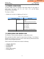
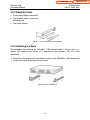
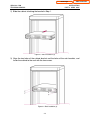
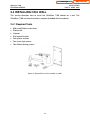
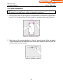
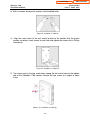
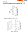
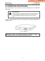
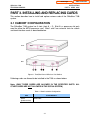
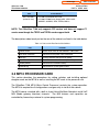
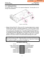
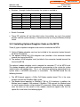
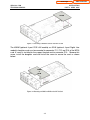
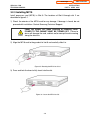
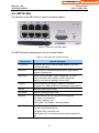
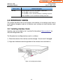
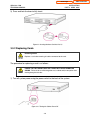
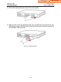
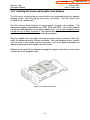
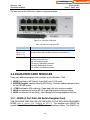
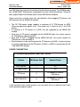
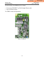
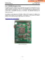
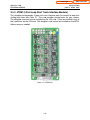
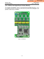
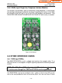
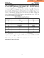
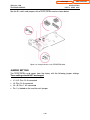
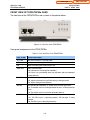
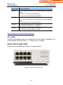
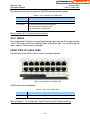
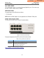
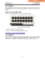
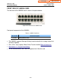
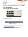
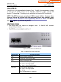
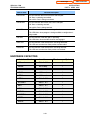
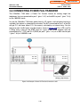
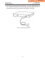
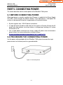
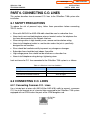
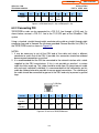
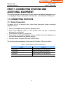
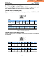
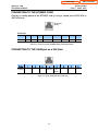
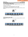
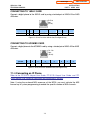
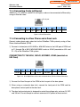
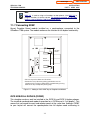
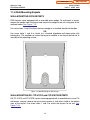
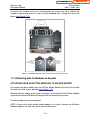
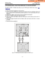
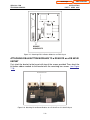
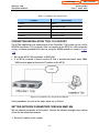
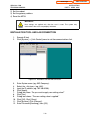
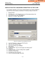

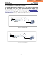
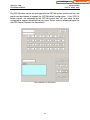
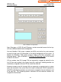


![SamsungProdBulletin_211_4_4x_Software_Release[1]](http://vs1.manualzilla.com/store/data/005825179_1-598976db56b1ef1012f4b9b7fb2b917f-150x150.png)