1
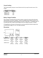
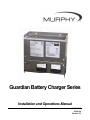
Guardian Battery Charger Series
Installation and Operations Manual
00-02-0615
02-29-08
Section 75
In order to consistently bring you the highest quality, full featured products, we reserve the right to change our
specifications and designs at any time. The latest version of this manual can be found at www.fwmurphy.com.
Warranty - A limited warranty on materials and workmanship is given with this FW Murphy product. A copy of
the warranty may be viewed or printed by going to www.fwmurphy.com/support/warranty.htm
Please read the following information before installing.
BEFORE BEGINNING INSTALLATION OF THIS MURPHY
PRODUCT:
•
Disconnect all electrical power to the charger.
•
Make sure the charger cannot operate during installation.
•
Follow all safety warnings of charger and battery
manufacturers.
•
Read and follow the Safety Instructions section of this manual.
•
Read and follow all installation instructions.
•
Please contact FW MURPHY immediately if you have any
questions.
Table of Contents
Safety Instructions.................................................................................................................. 1
General Safety Instructions ..........................................................................................1
Personal Precautions ...................................................................................................2
Prior to Installation / Commissioning ............................................................................2
Charger Location and Connection................................................................................3
General Product Information ................................................................................................. 4
Installation and Mounting Instructions................................................................................. 6
Operating Instructions ........................................................................................................... 7
Terminal Connection Information .................................................................................7
Troubleshooting.................................................................................................................... 10
Measuring Charging Voltage and Current ..................................................................11
Output Voltage ...........................................................................................................11
Using Correct Size Battery Charger ...........................................................................12
Factors Contributing to Electrolyte Loss.....................................................................12
Battery Life .................................................................................................................12
Specifications........................................................................................................................ 14
Power Supply .............................................................................................................14
DC Charge Output .....................................................................................................14
Charge Fail Output.....................................................................................................14
General ......................................................................................................................14
NOTES
Safety Instructions
This manual contains important safety and operating instructions for Guardian models BCEG12-10, BCEG-24-10, and BCEG-24-20.
General Safety Instructions
For safe and correct use of the unit, follow the steps below. Should you have any problems
and the unit does not function as expected, consult the “Troubleshooting Guidelines” section
located at the end of these manual.
•
Visually inspect unit for any signs of damage caused by transport or storage. Do
not operate charger if it has been damaged or abused. Return to supplier in this
event.
•
Mount charger as outlined in “Charger Location and Connection”, paying
attention to ambient temperature.
•
Ensure that AC line voltage is disconnected. Make sure to only connect to the
correct AC supply voltage.
•
Ensure unit is properly grounded.
•
Check batteries in accordance with manufacturer guidelines.
•
Check charger is correct for battery type and voltage.
•
Connect unit to batteries, observing correct polarity and ensuring a secure and
tight connection.
•
Switch on unit at electrical supply.
•
Do not expose charger to rain or snow.
•
Use of an attachment not recommended or sold by the battery charger
manufacturer may result in risk of fire, electric shock, or injury to persons.
•
Do not disassemble charger. Return to supplier when service or repair is
required. Incorrect reassembly may result in a risk of electric shock or fire.
WARNING – RISK OF EXPLOSIVE GASES
WORKING IN VICINITY OF A LEAD-ACID BATTERY IS DANGEROUS.
BATTERIES GENERATE EXPLOSIVE GASES DURING NORMAL
BATTERY OPERATION.
To reduce the risk of battery explosion, follow these instructions
and those published by battery manufacturers and manufacturer of
any equipment you intend to use in vicinity of the battery. Review
cautionary markings on these products and on any attached
equipment.
Section 75
02-29-08
00-02-0615
-1-
Personal Precautions
•
Someone should be within range of your voice or close enough to come to your
aid when you work near a lead-acid battery.
•
Have plenty of fresh water and soap nearby in case battery acid contacts skin,
clothing or eyes.
•
Wear complete eye protection and clothing protection. Avoid touching eyes while
working near batteries.
•
If battery acid contacts skin or clothing, wash immediately with soap and water.
If acid enters eyes, immediately flood eyes with running cold water for at least 10
minutes and get medical attention immediately.
•
NEVER smoke or allow a spark or flame in vicinity of battery.
•
Be extra cautious to reduce risk of dropping a metal tool onto battery. It may
spark or short-circuit the battery or other electrical part that may cause explosion.
•
Remove personal metal items such as rings, bracelets, necklaces, and watches
when working with a lead-acid battery. A lead-acid battery can produce a shortcircuit current high enough to weld a ring or the like to metal, causing a severe
burn.
•
Use charger only for charging batteries as marked on the charger. Do not use
battery charger for charging dry-cell batteries that are commonly used with home
appliances. These batteries may burst and cause injury to persons and damage
to property.
•
NEVER CHARGE A FROZEN BATTERY.
Prior to Installation / Commissioning
•
Clean battery terminals. Be sure to keep corrosion from coming in contact with
eyes.
•
Add distilled water in each cell until battery acid reaches level specified by
battery manufacturer. This helps purge excessive gas from cells. Do not overfill.
For a battery without cell caps, carefully follow manufacturer’s recharging
instructions.
•
Study all battery manufacturer’s specific precautions such as removing or not
removing cell caps while charging and recommended rates of charge.
•
Determine voltage of battery by referring to engine manual and ensure matches
charger’s output voltage.
Section 75
02-29-08
00-02-0615
-2-
Charger Location and Connection
•
The charger must be mounted inside. This device is not weather-proof. Free air
flow is required from below and out the top of the unit.
•
Do not operate charger in a closed-in area or restrict ventilation in any way.
•
Never place charger directly above battery being charged as gases from battery
will corrode and damage charger.
•
Never allow battery acid to drip on charger when reading specific gravity or filling
battery.
•
The battery charger should be connected to a grounded, metal, permanent wiring
system.
•
Connections to battery charger should comply with all local codes and
ordinances.
•
AC wiring should be run separately from the output of the charger and the alarm
wiring. Use two runs of 12 gauge or heavier wire from the charger to the battery.
Use 12 gauge or larger wire for input and ground connections.
NOTE: Follow all national and local wiring codes and best practices.
Section 75
02-29-08
00-02-0615
-3-
General Product Information
Please read the following information before installing. A visual inspection of this product for
damage during shipping is recommended before installation. It is your responsibility to ensure
that qualified mechanical and electrical technicians install this product.
The Guardian charger provides automatic, current limited and voltage controlled charging of
vented lead acid batteries. It may be used in a wide range of industrial charging applications,
including batteries for standby engines, pumps and generators.
This charger is designed for connection to only one battery. Do not use more than one charger
per battery, or more than one battery per charger.
The charger is supplied in an enclosed stainless steel panel suitable for wall mounting.
NOTE: In event of no AC supply to charger, the voltmeter will display the DC
voltage of any connected DC equipment.
Each unit consists of a transformer, rectifier and thyristor control circuit. The control circuit
ensures that the charger maintains a battery voltage at the pre-calibrated float level, while
supplying any additional load current up to the specified maximum.
Auto Boost (Equalizing) Operation
Auto boost operation provides an increased output voltage when batteries are below a preset
point. Once the batteries have reached the boost voltage the charger reverts to its float
voltage. This operation equalizes the batteries, maximizing battery life and capacity.
Boost Initiate Operation
The boost initiate switch forces the charger to enter an auto boost cycle even if battery voltage
is above the preset point. Once this operation is completed the charger returns to it’s float
voltage.
Temperature Compensation
The remote temperature compensation provides control of the output voltage based upon
temperature. As temperature increases the charging voltage is decreased at a negative
coefficient of 3mV/°F/Cell.
Charge Fail and Alarms
A self diagnosis ‘charge fail’ circuit and relay output is provided along with under and over
voltage warnings. The dry contact relay outputs de-energize in the event of a charging fault or
high/low battery state.
Electrical connection of the AC supply and DC output and alarms are via spring-clamp
terminals.
Section 75
02-29-08
00-02-0615
-4-
Current Limiting
The Guardian battery charger is current limited and will only output the rated current of the
charger.
Guardian Current Ratings
Model
Rating
BCEG-12-10
10A
BCEG-24-10
10A
BCEG-24-20
20A
Battery Charged Condition
When charged, the battery will only accept a charge to replace the losses within the battery
(approximately 1mA per AH of battery). If there is a standing load (the panel controller, etc.)
the charger will output the standing load plus the losses to the battery. If a standing load of 1A
is present with 50AH Vented Lead Acid batteries then the charger will supply 1.05 amps.
A charged battery with open circuit terminals (no load connected) will always be higher than
nominal battery voltage (12.6 on a 12V lead acid battery).
Dimensions
Model
BCEG-12-10
BCEG-24-10
BCEG-24-20
Section 75
02-29-08
W
10.83”
(275mm)
10.9”
(278mm)
13.19”
(335mm)
D
4.92”
(125mm)
4.7”
(120mm)
7.71”
(145mm)
H
11”
(280mm)
11”
(280mm)
12.20”
(310mm)
Weight
22 lbs.
(10.0Kg)
22 lbs.
(10.0Kg)
38.5 lbs.
(17.5Kg)
00-02-0615
-5-
Installation and Mounting Instructions
Mounting hole dimensions:
Width (between holes) – 6.77” (172mm)
Height (between holes) – 10.04” (255mm)
Mounting holes 0= 0.2” (6mm)
•
The charger must be mounted as shown in the figure above.
By unscrewing the mounting screws the faces can be opened on their hinges to
allow access to the internal connections.
•
Cable entry is via ½” conduit knock-outs on either side of the unit. These must
be carefully removed from the enclosure sides.
•
A suitable cable-gland (0.8” DIA/20mm) should be used to prevent damage to
cables and stop unwanted entry into inner part of charger. See “Terminal
Connection Information” section of the chapter on Operating Instructions for
details of terminal connections.
•
The lower face should be firmly screwed to the charger before use.
•
Four screws should be used to mount charger to panel. Ensure screws are
tightened firmly as not to become loose during normal operation.
•
Adequate consideration should be given to ventilation for proper heat dissipation.
CAUTION: When handling chargers, do not do anything that will cause any
stress on the internal devices or wiring. Nothing should be mounted or hung
inside the enclosure. Only connect the appropriate wires inside the enclosure.
Unit should be handled by steel enclosure.
Guard against debris from mounting, wiring, or connection to conduit entering the
enclosure. Do not allow metal cuttings or filings to enter the enclosure. Make
sure no moisture or oil can drip inside the enclosure.
Section 75
02-29-08
00-02-0615
-6-
Operating Instructions
Before operating the battery charger, ensure that the charger is assembled and installed as
per the installation instructions.
WARNING: DANGER OF INJURY OR DEATH
Before connection, disconnection or handling of Guardian battery
charger, be sure AC power supplies are off.
NOTE: Connection to or disconnection from live wiring can also cause damage
to internal components.
Terminal Connection Information
Output:
To battery
CAUTION: Observe correct polarity
Input:
AC supply
CAUTION: Observe correct voltage as stated on unit.
Alarm Indication
Over voltage, under voltage and charge fail
Boost:
Boost initiate – Linking these two connectors will force the charger into a
single boost cycle of operation. Once the charger has completed a single
boost cycle the charger returns to its normal mode of operation.
Stripped wire is introduced just before the clamping unit.
The clamp spring is pressed down and wire is introduced into the
clamping unit immediately.
The clamp spring is released – the conductor is automatically clamped.
NOTE: All connections, including AC input and DC output are made via springclamp connections as outlined above.
Section 75
02-29-08
00-02-0615
-7-
The BCEG-12-10 and BCEG-24-10 models are fitted with a self-resetting polyfuse on the DC
output. If reverse polarity or short circuit faults occur, turn off AC power and disconnect the
outputs. This will allow the polyfuse to reset. The charger can then be re-connected and
switched back on. No replacement of output fuse should be necessary. If fuse fails to reset,
the charger should be returned to supplier. BCEG-24-20 models are fitted with an automotive
type blade fuse. Ensure correct rating when replacing fuses.
Automatic Battery Charger
The Guardian is an automatic battery charger. If battery voltage falls below a preset voltage
(12.2V on a 12V lead-acid battery) the charger will automatically enter an increased charging
voltage state (boost). Once the batteries have reached a charged state, the charger will switch
to it’s normal “float” voltage. This prevents over-charge, which in turn prevents the battery
from over-gassing and subsequently maximizes battery life.
Connection to Power Supply
Ensure supply is off before connection is made to charging unit. Ensure unit is properly
grounded to the charger’s metal chassis.
CAUTION: Ensure correct AC voltage is supplied to unit. Applying 240VAC on
a 120VAC unit will destroy it and could cause serious personal injury.
Connection to Batteries
Ensure power supply is off before connecting charger to batteries. Ensure battery type and
voltage are correct before connecting to batteries.
WARNING: Charging either different voltage or type of batteries from stated
type may result in damage to both the charging unit and/or batteries and could
result in serious personal injury.
Disconnection of Batteries
Ensure power supply is off before disconnecting charger from batteries.
WARNING: Disconnecting the batteries while power supply is connected to the
charger could result in a spark at battery terminals, which could ignite the
hydrogen given off from the batteries.
Boost Initiate Connection
The charger will be in it’s normal mode of operation while the boost link is broken. Upon
connecting the two boost initiate terminals the charger will perform a single auto-boost cycle.
While the charger outputs a higher voltage, once the battery voltage has reached this point,
the charger returns to it’s normal float mode of operation.
Section 75
02-29-08
00-02-0615
-8-
Over Voltage, Under Voltage, and Charge Fail Connection
In a de-energized state the COM – N/C contact is alarmed. The relay energizes on power up
and changes state to COM – N/O. These contacts are volt-free contacts rated at 1A @
30VDC.
Fuses
All Guardian models are fitted with fuses at the required ratings. Before replacing any fuses,
ensure charger is off from power supply.
Section 75
02-29-08
00-02-0615
-9-
Troubleshooting
Section 75
02-29-08
00-02-0615
- 10 -
Measuring Charging Voltage and Current
To check the charger is working, follow these steps then consult the expected conditions listed
below.
1. VOLTAGE – Place voltmeter across battery terminals (“V” in diagram).
2. CURRENT – Turn off AC power supply before breaking into the line to measure DC
Amps. Break the positive line to the battery and place an ammeter between positive
from charger and positive of battery (“A” in diagram).
Current Flow from Charger to Battery
If voltage at terminals is less than nominal battery voltage then the maximum rated charger
current should be present.
NOTE: Once battery is fully charged, output current should be between 0.1%
and 0.5% of batteries AH capacity plus any standing loads.
Voltage Rise at Battery Terminals
A gradual rise of voltage should be seen showing as float voltage is reached – batteries should
not be boost charged continuously.
NOTE: If the battery voltage increases rapidly during charge and no minimum
current is measured then the battery may have become sulphated and will not
hold charge and may be unrecoverable.
Output Voltage
12/v
24/v
Float:
13.6V
24.2
Boost:
14.1
28.2V
Typical output with no battery or load
connected. For all Guardian models the
precalibrated float voltage should be present.
LEAD
ACID
Section 75
02-29-08
00-02-0615
- 11 -
Using Correct Size Battery Charger
The battery charger will need to provide both the standing load and minimum charge current.
If a charging current of 2 amps is required, and the standing load is 1 amp, then the charger
needs to be able to output a total of 3 amps.
Refer to genset manual for sizing of battery chargers to generator set. If installing your own
chargers, lead acid battery manufacturers recommend the following:
•
Minimum charge current should be approximately 5% battery AH capacity.
•
Maximum charge current to be equal to 25% battery AH capacity
NOTE: When batteries are normally charged by a charging alternator, a float
battery charger rated at lower than the minimum charge current is sufficient to
keep batteries in fully charged state.
Factors Contributing to Electrolyte Loss
•
Physical damage to cells can cause electrolyte to leak or evaporate.
•
High charging voltages will evaporate electrolyte.
Check charging voltage against battery type and voltage.
WARNING: If the batteries are being used at above 20° Celsius, the chargers
output voltage should be temperature compensated at -3mV/°F/Cell.
Battery Life
Two possible methods can be used for determining battery life:
•
Using Hydrometer
•
Using a digital DC voltmeter
Follow these steps to check battery life.
1. Fully charge the batteries.
2. Disconnect batteries and leads and leave for 24 hours.
3. Measure either specific gravity (hydrometer) or terminal voltage (voltmeter) and
compare with the table on the following page.
4. If time is limited due to on-site testing, remove surface charge by either applying a 20
amp load for 3 minutes or crank engine for 10 seconds, then disconnect batteries and
leads and leave for minimum of 10 minutes.
Section 75
02-29-08
00-02-0615
- 12 -
NOTE: On this method, providing batteries have been sized correctly for engine
and charged correctly, an open terminal voltage of 12.5V or greater should be
present.
The following table is for Lead Acid batteries with removable vent caps that can have
electrolyte or distilled water added to them for routine maintenance.
% Charge
Specific Gravity
100
75
50
25
Discharged
1.265
1.225
1.19
1.155
1.12
Voltage (DC) on
a 12V battery
12.8
12.5
12.4
12.0
11.5
NOTE: If the voltage across the terminals shows around 10.5V, this may
indicate a shorted cell is present.
Section 75
02-29-08
00-02-0615
- 13 -
Specifications
Power Supply
•
Nominal operating voltages – 120V Units
•
Permissible voltage variation - ± 6% of nominal
•
Nominal operating frequency – 50/60Hz
DC Charge Output
•
Maximum current ADC – 20
•
Nominal voltage VDC – 12 or 24
•
Float/boost voltages
These are factory preset for specified batteries, typical settings are as follows:
Vented lead acid – Float voltage – 12V / 13.6V and 24V / 27.2V
Vented lead acid – Boost voltage – 12V / 14.1V and 24V / 28.2V
Charge Fail Output
• Relay type – volt free SPDT contacts relay de-energized on fault.
• Contact rating – 1A @ 30VDC (resistive load)
General
• Transformer – Single phase 50-60 Hz Class 155 (F)
• Operating temperature - +14°F to +131°F (-10°C to +55°C)
• Wall mounted enclosure models
• BCEG-12-10, BCEG-24-10 – dimensions 10.9”/278mm(W) x 4.7”/120mm(L) x
11”/280mm(H); weight 22 pounds / 10.0Kg
• BCEG-24-20 – dimensions 11.8”/300mm(W) x 11.8”/300mm(L) x 8.3”/210mm(H), weight
38.5 pounds / 17.5Kg
• EMC emission/immunity – EN58801-2 / EN50082-2
Section 75
02-29-08
00-02-0615
- 14 -
MURPHY and the Murphy logo, are registered and/or common law trademarks of Murphy Industries, Inc. This
document, including textual matter and illustrations, is copyright protected by Murphy Industries, Inc., with all
rights reserved. (c) 2007 Murphy Industries, Inc. Other third party product or trade names referenced herein are
the property of their respective owners and are used for identification purposes only.
Section 75
02-29-08
00-02-0615
- 15 -
CALL MURCAL TO PLACE YOUR ORDER
P:(661)272-4700 F:(661)947-7570
www.murcal.com
e-mail: [email protected]
MurCal
c