1
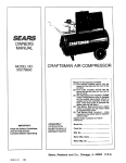
S_FA/RS
OWNERS
MANUAL
MODEL NO.
919.17673g
919.17683
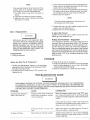
CRAFTSMAN AiR COMPRESSOR
Record in the spaces provided.
(1) The model number which can be
found on the tabel on the rear of the
air tank.
(2) The code number
which can be
found on the foil tabel on the rear of
the air tank.
(3) The Manufacturers
Number
(MFG.,.)
{ASME Code Compressors onty) is located on the metst
date plate which is welded onto the
backside of the air tank. (This data
plate is painted the same cotor as the
tank.)
(4) The Motor Manufacturers
name
which is mocated on the motor tabel
or specification plate.
(5) The Motor
Mfg. numberatso
_ocsted on the motor _abel or specifF
cation plate,
Retain these numbers for future
reference.
aMPORTANT:
Read the Safety Guidelines
and AH instructions
Carefully Before Operating
ASSEMBLY
OPERATION
MAINTENANCE
REPAIR PARTS
Model No
Code No .............................................................
Mfg. No,
Motor Mfg. Name
Motor Mfg. No
Sears,
SI-30-14-4-D
6/89
Roebuck
and Coo, Chicago,
IL 60684
U.S.A.
TABLE OF CONTENTS
Page
..................................................................
SAFETY
GU_DEUNES
WARNING
3
........................................................
3
CHART .............................................................
3
SPECIFICATION CHART ......................................................
5
GLOSSARY
5
....................................................................
ACCESSORIES
GENERAL
FOR USE WiTH SEARS
AIR COMPRESSORS
mNFORMATHON ....................................................
DESCRIPTION
OF OPERATION
..............................................
.............
¢
6
6
ASSEMBLY
_NSTRUCTNONS
..................................................
Items You Witt Need to Assemble Your Compressor ................................
Installing Handle ..............................................................
Installing Rubber Foot Strip and Wheels ..........................................
hstalling Tank Pressure Gauges .................................................
Installing Regulator ............................................................
7
7
7
8
8
8
9NSTALLATmON AND BREAKqN
PROCEDURES
.............................
Location of Air Compressor .....................................................
Extension Cords ..............................................................
Lubrication and Oil ............................................................
Grounding hstructions .........................................................
Break-in Procedures ...........................................................
8
8
8
8
9
9
OPERATING
9
PROCEDURES
MAINTENANCE
................................................
..............................................................
Air Filter - Inspection and Replacement ..........................................
Oil - Checking and Changing ...................................................
Check Valve - Replacement ....................................................
Safety Valve - Inspection .......................................................
Motor ........................................................................
Belt - Replacement ............................................................
Pulley and Flywheel - Alignment ...............................................
STORAGE
...................................................................
TROUBLESHOOTING
A_R COMPRESSOR
GUIDE .................................................
DIAGRAM
...............................................
Parts List ....................................................................
COMPRESSOR
PUMP DIAGRAM
............................................
Parts List ....................................................................
HOW TO ORDER
REPAIR PARTS ............................................
lo
10
10
10
10
10
11
11
11
11
14
16
15
!7
18
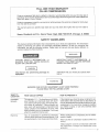
FULL ONE YEAR WARRANTY
ON
COMPRESSORS
if this air compressor fans due to a defect in material or workmanship within one year from the date of
purchase, return it to the nearest Sears Service Center/Department throughout the United States and
Sears wiii repair it, free of charge.
If this air compressor is used for commercial or rental purposes, the warranty wit! apply for ninety days
from the date of purchase_
This warranty gives you specific legal rights and you may have other rights that vary from state to
state.
Sears,
Roebuck
and COo, Sears Tower, Dept. 698/7131OR=W,
SAFETY
Chicago,
IL 60684
GUiDELiNES
This manual contains information that is important for you to know and understand. This information
relates to protecting your safety and preventing equipment problems. To help you recognize this
information, we use the following symbols. Please read the manual and pay special attention to
sections headed by these symbols.
URGENT
SAFETY
_NFORMATNONA
HAZARD
THNr W_LL CAUSE SEmOUS
_NJURY OR LOSS OF LIFE
IMPORTANT SAFETY _NFORMATION .- A
HAZARD THAT M_GHT CAUSE SERIOUS
INJURY OR LOSS OF LIFE,
NOTE
Information
equipment.
for
preventing
damage
to
information that you should pay special attention to.
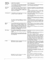
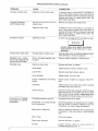
HAZARDS CAN OCCUR _F EQUIPMENT IS NOT USED PROPERLY:
PLEASE READ THE FOLLOWING CHART,
WHAT TO
LOOK FOR
WHAT COULD HAPPEN
HOW TO PREVENT mT
Unsuitable
Sobvents
The solvents 1,1,1- Trichlorethane and Methylene Chloride can chemically react with aluminum used in paint spray guns, paint pumps, etc.,
and cause an explosion. These solvents can
also react with galvanized components and
cause corrosion and weakening of parts. This
does not affect your air compressor- but it may
affect the equipment being used.
If the material you intend to spray contains the solvents listed at left (read the labei or data sheet), do
not usa accessories that contain aluminum or galvanized parts. You must either change the material
you intend to spray, or usa only stainless steel
spray equipment.
Electricity
Your air compressor is powered by electricity.
Like any other electrically powered device, if it is
Always unplug the air compressor prior to maintenance or repair.
not used properly it can cause electrical shock.
Never use the air compressor outdoors when it is
Always plug the cord into an electrical outlet with
the specified
voltage
and adequate
fuse
3
WHATTO
LOOK FOR
WHAT COULD HAPPEN
NOW TO PREVENT }T
Hot Parts
The compressor head and tubes get hot when
the air compressor is running. If you touch them,
you can be seriously burned.
Never touch the air compressor head or tubes daring or immediately after operation.
Flammable
Vapors
It is normal for the motor's electrical contacts to
spark when the compressor starts or stops. A
spark can ignite flammable
vapors from
Operate the compressor in well ventiIated areas
thatarefreeofgasotine,
flammablepaintorsoivent
vapors.
gasoline, flammable paints or solvents and
cause a fire or explosion.
if spaying a flammable material - provide ample
ventilation. Never spray in a closed area. There
must be a flow of fresh ad at alt times.
Compressed air can propel dust, dirt or loose
particles it comes in contact with.
Never point any nozzle or sprayer toward a person
or any part of the body.
Compressed Air
Always wear safety goggles or glasses when using
the air compressor.
Always turn the air compressor off and release air
pressure from hose before attaching or removing
accessories.
Moving
Parts
Toxic 'Vapors
Too much air pressure applied to air tools or
accessories
can cause damage or risk of
bursting.
Check the manufacturer's maximum pressure rating for air tools and accessories. Regulator outiet
pressure must never exceed the maximum pressure rating.
This compressor cycles automatically when the
switch is in the "On-Auto" position. If you
attempt repair or maintenance while the compressor is operating, or with the switch in the
"On-Auto" position, you can expose yourself to
moving parts. These moving parts can cause
serious injury or damage, if they come into contact with you or your clothing.
Always unplug the unit and release air pressure
from the tank and any accessories before doing
repair or maintenance.
It is normal for compressed air to contain toxic or
irritating vapors. Such vapors are harmful if
inhaled.
Never directly inhale the compressed air produced
by this unit.
Certain materials you are spraying (like paint,
weed killer, sand or insecticide) can be harmfu!
if you inhale them.
Air Tank
Modifications to the air compressor can cause
the air tank to rupture or explode.
Never operate the compressor with the belt guard
removed.
Read labels and safety data for all materials you
spray. Follow alI safety precautions.
Use a mask or respirator if there is a chance of
inhating toxic sprayed materials. Masks and
respirators have timits and will only provide protection against some kinds and limited amounts of
toxic material. Read mask and respirator instructions carefully. Consult with a safety expert or
industrial hygienist if you are not sure about the use
of a certain mask or respirator.
Do not adjust, remove or tamper with the safety
vatve or pressure switch. If safety valve or pressure
switch replacement is necessary, a part with the
same pressure rating must be used.
For service replacement use only the motors, pulleys and belts designed as standard service
replacement parts as indicated in the parts list.
Use of improper parts could cause overloading of
your unit and electrical supply.
Do not substitute a gas engine for the motor.., this
compressor was not designed to be powered by a
gasoline engine.
Never replace the compressor pump with a differ_
ent model
Never increase the compressor pump speed.
Changing the air tank wi!! cause it to weaken.
The tank can rupture or exptode.
Never drilt into, weld, or in any way modify the air
tank. Do not repair a leaking tank, it must be
replaced.
Never replace the air tank with a different model or
a larger tank.
4
SPEC_FICATION
CHART
Modem No.
Horsepower
Displacement CFM
Bore
Stroke
Voltage-Single Phase
Minimum Branch Circuit Requirement
*Fuse Type
919.176730
3
11.3
2%"
2"
!20/240"*
!5 amp***
Fusetron
Type "T"
20
80
100
8.8
Z7
7.3
Yes
Air Tank Capacity -Galfons
Approximate Cut-in Pressure
Approximate Cut-out Pressure
SCFM {u 40 psig
SCFM (_., 90 psig
SCFM (t_ 100 psig
U.L Listed
9t&176830
3
11.3
2%"
2"
120/240"*
15 amp***
Fusetron
Type "T"
20 ASME
80
100
8.8
7.7
7.3
Yes
**These models have dual voltage motors, !20 and 240 volt. They are WIRED FOR 120 VOLT but can be converted to 240
volt operation. Instructions for connecting the motor for operation at 240 volt can be found printed on the inside of the
motor cover or on the nameplate of the motor.
*A circuit breaker is preferred. Use only a fuse or circuit breaker that is the same rating as the branch circuit the air
compressor is operated on. If the air compressor is connected to a circuit protected by fuses, use dual element time
delay fuses (Buss Fusetron Type "T" only).
These air compressors
a 15 amp circuit if:
can be operated
4. Circuit is equipped with 15 amp circuit
breaker or 15 amp Fusetron Type"T" time
demay fuse.
on
1. Vomtage suppmyto circuit is normat.
2o Circuit is not used to supply any other
electrical needs (lights, appliances, etc°}
3. Extension cords comply with specifications in owners manual
If any of the above conditions cannot be met, or if operation of the compressor repeatedly causes interruptionof
the power it may be necessary to operate it from a 20
amp circuit. It is not necessary to change the cordset if
this change is required.
When converting this model to 240 volt opera=
rice, the attached three-prong
120 vo_t pJug
must be replaced with a three-prong
240 volt
p_ug (purchase locally) or order line cord Part
No, SUDL-4044.
GLOSSARY
CFM: Cubic feet per minute.
SCFM: Standard cubic feet per minute; a unit of measure of air delivery.
PSIG: Pounds per square inch gauge; a unit of measure
of pressure.
ASME: American Society of Mechanical Engineers;
made, tested, inspected and registered to meet the standards of the ASME.
U.L° Listed: Underwriter Laboratories; Samples of
compressor outfits, taken from production, were submitted to U.L and found to comply with their requirements for design and performance
Cut4n Pressure: While the motor is off, air tank pressure drops as you continua to use your accessory. When
the tank pressure drops to a certain iow level the motor
wif! re-start automatically. The low pressure at which the
motor automatically re-starts is caIled "cut-in pressure,"
Cut-Out Pressure: When you turn on your air compressor and it begins to run, air pressure in the air tank begins
to build. It builds to a certain high pressure before the
motor automatically shuts off - protecting your air tank
from pressure higher than its capacity, The high pressure at which the motor shuts off is called "cut-out
pressure."
5
ACCESSORIES
FOR USE WiTH SEARS
COMPRESSORS
The following accessories are available through the current general sales catalog or at fuliqJne Sears stores.
,SPRAY GUNS
.PAINT TANKS
,AIR TOOLS:
°BLOW GUNS
oAIR TANKS
Sanders
oAIR CAULKING GUNS
•INFLATOR KITS
Drills
oQUICK CONNECTOR SETS
oAIR POWERED WASHER GUNS
Impact wrenches
Hammers
,SAND BLASTERS
(various sizes)
oVISCOSIMETER
,AIR HOSE:
°AIR BRUSHES
oAIR LINE FILTERS
,AIR PRESSURE REGULATORS
1/4", 5/16" OR 3/8" LD.
oOIL FOG LUBRICATORS
oTIRE AIR CHUCKS
in various lengths.
GENERAL
iNFORMATiON
You have purchased an air compressor unit consisting of
a 2 cylinder, single stage air compressor pump, an air
tank, air hose, wheels, handte, air chuck and associated
controls.
An in-line lubricator is usually required for air tools to
prolong toot life.
Separate air transformers which combine the functions
of air regulation and/or moisture and dirt removal should
be used where applicable.
Your air compressor can be used for operating paint
spray guns, air tools, caulking guns, grease guns, air
brushes, sandblasters, power washers, inflating tires
and plastic toys, spraying weed killers, insecticides, etc.
These accessories can be purchased from most Sears
stores or through the Sears General catatog or Power
Toot catalog.
An air line filter is usually required for removal of moisture and oil vapor in compressed air when a paint spray
gun is used.
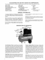
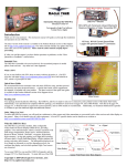
VALVE
VALVE
)RAIN
VALVE
Air Compressor
Pump: To compress air, the pistons
move up and down in the cylinders. On the downstroke,
air is drawn in through the air intake filter and then
through the air intake valves. The exhaust valve remains
closed. On the upstroke of the piston, air is compressed.
The intake valves close and compressed air is forced
out through the exhaust valve, through the outlet tube,
through the check vatve and into the air tank. Working air
is not available until the compressor has raised air tank
pressure above that required at the air outlet.
Check Vatve: When the air compressor is operating, the
check valve is "open", allowing compressed air to enter
the air tank. When the air compressor reaches "cut-out"
pressure, the check vaIve "closes", aJlowing air pressure
to remain inside the air tank.
Pressure Remeaee Valve:The pressure release valve
located on the side of the pressure switch, is designed to
automatically release compressed air from the compressor head and the outlet tube when the air compressor reaches "cut-out" pressure or is shut off. If the air is
not release& the motor wilt try to start, but will be unable
to. The pressure release vatve allows the motor to restart freely. When the motor stops running, air wilt be
heard escaping from the valve for a few seconds. No air
should be heard leaking from the valve when the motor is
running.
Safety Valve:tf the pressure switch does not shut off the
air compressor at or near its cut-out pressure setting, the
safety valve will protect against high pressure by "popping out" at its factory-.set pressure (slightJy higher than
the pressure switch cut-out setting).
PressureSwitch: The pressureswitchautomatically
startsthemotorwhenthesirtankpressure
dropsbelow
thefactoryset"cat-in"pressure,
itstopsthemotorwhen
theair tankpressurereachesthefactoryset"cut-out"
pressure.
Regumstor:
The
air pressure coming from the air tank is
controlled
by the regulator knob. Turn the knob
clockwise to increase pressure and counterclockwise to
decrease pressure. To avoid minor readjustment after
making a change in pressure setting, always approach
the desired pressure from a lower pressure. When
reducing from a higher to a !ower setting, first reduce to
some pressure tess than that desired, then bring up to
ASSEMBLY
totems You WiN Need To Assemble
the desired pressure. Depending on the air requirements
of each particular accessory, the outlet regulated air
pressure might have to be adjusted while you are
operating the accessory.
Tank Pressure Gauge: The tank pressure gauge indicates the reserve air pressure in the tank.
Outlet Pressure Gauge: The outtet pressure gauge
indicates the air pressure available at the outlet side of
the regulator. This pressure is controfled by the regulator
and is always less or equal to the tank pressure. See
"Operating Procedures."
INSTRUCTIONS
Your
Compressor
.16 oz, compressor oil, Sears 9-16426 or SAE 20-20W
SF motor oil
o pipe thread sealant
an adjustable wrench for attaching the pressure
regulator
o a 9/16" socket or open-end wrench for attaching the
wheels and hose adapter
• a 7/16" open-end wrench for attaching the air pressure
gauges
o a 3/16" hex key for installing the plug in the regulator
OF SADDLE
BENT
TABS
OPEN
SAD_
END
OF HANDLE
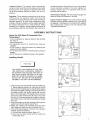
Jnstamling Nandme
FIG. 1
TNE WREELS AND HANDLE DO NOT PRO,
VDE ADEQUATE CLEARANCE
STAB_UTY
OR SUPPORT FOR PULUNG TRE UNiT UP
AND DOWN STAIRS OR STEPS= TRE UNIT
MUST B£ L_ETED OR PUSNED UP A RAMP°
DO NOT UPT TNE UNiT BY THE _IAN_FOLD
ASSEMBL'£ THE UNiT CAN BE DAMAGED
1. Insert the open end of the handle under the saddle (Fig.
t). Before attaching handle, you may have to pull the
open ends of the handle apart so they fit tightly against
the side of the saddle. Looking in from the open end of
the saddle, position the handle towards the two bent
tabs, on the inside waits of the saddle. S!owly push the
open ends of the handle onto both tabs at the same
time (Fig. 2). Continue pushing the handle into the saddle until the holes on the side of the saddle and handle
are in line.
2. Guide the straight end of each retaining clip through the
saddle hole and both handle holes (Fig. 3).
3. Rotate each retaining clip clockwise and press down
until it snaps into place over the putI handle (Fig. 4).
4. If the handle has excessive movement, it is improperly
installed. Check the following:
A. Are both tabs inside the handle (Step #1)?
B. Does each clip pass through both the saddle and
handle (Step #2)?
BENT TAB
(ONE ON
EACH SEDE)
OPEN END
OF HANDLE
FHG.2
FgG. 3
7
_nataHing Tank Pressure
Gauge
Apply pipe sealant (not supplied) to the gauge threads
and install in the threaded opening in front of the
manifold. Refer to photo on pg. 6_
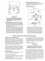
InstatSing Regulator
(Top View}
PLUG
GUARD
REGULATOR
t
Jt may be necessary to brace or support one
end of the outfit when attaching the wheels
because the air compressor will have a
tendency to tip.
mnstagJiag Rubber
t. Remove the protective paper strip from the adhesivebacked rubber foot strip. Attach the rubber foot strip to
the bottom of the air tank leg, Press firmly into place.
(See page 14 key no. 39.)
2. The leg bracket on the underside of the air compressor tank has 2 holes on each side for mounting the
wheels. Place one shoulder bolt through the hote in a
wheel. Next, push the bolt through the LOWER hole of
the leg bracket and screw on one hex locking nut. The
special locking nut does not turn freely. Tighten the
nut firmly until it contacts the leg. See pg. 14. The
outfit will set level if the wheels are properly installed.
Location
of the Air Compressor
If humidity is high, a Sears air filter can be insta!led on
the air outlet adapter to remove excessive moisture, and
oil vapor from the air. Closely foilow the instructions
packaged with the filter for proper installation. _tmust be
installed as close as possible to the accessory.
Cords
To avoid voltage drop and power loss to the motor, use
extra air hose instead of an extension cord,
tf an extension cord must be used:
o use only a 3-wire extension cord that has a 3-blade
grounding piug and a 3-slot receptacle that wilt accept
the plug on the product.
o make sure the extension cord is in good condition.
• the extension cord should be no longer than 50 feet.
8
_._
REGULATED
PRESSURE GAUGE
MAN_=
FOLD
NOTE
Use a small amount of pipe thread seatant (not
supplied} on ali pipe thread joints. Install the
regulator on the end of the manifold using the
short pipe hippie. The arrow on the bottom of
the regulator must point away from the manifold
in order for the regulator to function properly'.
Next, install the gauge, adapter and plug in the
regulator. The ptug is supplied with the regulator.
AND BREAK= N
Operate the air compressor in a clean, dry and well
ventilated area. The air filter must be kept clear of
obstructions which could reduce air delivery of the air
compressor. The air compressor should be Iocated at
least 12" away from wails OFother obstructions that could
interfere with the flow of air through the fan bladed flywheel. The air compressor crankcase and head are
designed with fins to provide proper cooling.
Extension
ADAPTER
Foot Strip and Wheels
NSTALLATJON
PiPE
N_PPLE
PROCEDURES
° the minimum wire size is t2 gauge (AWG}. Sears #983606, 12 gauge x 50' extension cord is available at
your local Sears Service Center. (Wire size increases
as gauge number decreases. 10 AWG and 8 AWG may
also be used. DO NOT USE !4 AWG or 16 AWG.)
Lubrication
and OH
Compressors are shipped without oil Do
not attempt to operate this air compressor
without first adding oi_ to the crankcaaeo
P!ace unit on a levet surface. Remove oil fill plug (Key no.
81, pg. 15) and slowly add a speciat compressor oil such
as Sears 9-16426 or SAE 20_20W SF motor oil until it is
even with the top of the oi! fill hole. (it must not be aliowed
to be Iower than 3/8"- 6 threads down - from the top, at
any time.) When ill!rig the crankcase, the oil flows vary
slowly. If the oil is added too quickly, it will overflow and
appear to be full. Crankcase oiI capacity is 16 fad
ounces. Under winter-type conditions use SAE 10W oil.
Multi-viscosity oil, 10W 30_witl teave carbon deposits on
critical components reducing performance and compressor iife. Reptace oil fill plug.
Grounding
If these grounding instructions are not completely
understood, or if you are not sure your compressor is
property grounded, have the installation checked by a
qualified electrician.
_nstructions
iMPROPER GROUNDING CAN RESULT tN
ELECTRICAL SHOCK= IN THE EVENT OF A
SHORT CIRCUIT, GROUNDING REDUCES
THE RiSK OF SHOCK BY PROViDiNG AN
ESCAPE WiRE FOR THE ELECTRIC CURRENT, THIS A_R COMPRESSOR MUST BE
PROPERLY GROUNDED.
1. The air compressor is equipped with a cord having a
grounding wire and an appropriate grounding plug=
The plug must be used with an outlet that has been
installed and grounded in accordance with alt local
codes and ordinances. The outlet must have the
same configuration as the plug. DO NOT USE AN
ADAPTER.
2. Do not modify the plug that has been provided. If it
does not fit the available outlet, the correct outlet
should be installed by a qualified electrician.
3. Inspect the plug and cord before each use. Do not use
the compressor if there are signs of damage.
ELECTRICAL
SHOCK HAZARD.
WHEN
REPAmRING OR REPLACING THE CORD OR
PLUG, KEEP THE GROUNDING W_RE SEPARATE FROM THE CURRENToCARRYmNG
W_RES. NEVER CONNECT THE GROUNDgNG W_RE TO A FLAT BLADE PLUG TER=
MINAL,
(THE GROUNDING
W_RE HAS
INSULATION WITH AN OUTER SURFACE
THAT IS GREEN - WSTH OR W_THOUT YELLOW STRIPES.)
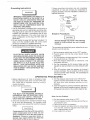
OPERATING
1. Before attaching an air hose or accessory', make
sure the pressure switch lever is in the "OFF" position. Close the air regulator outlet by turning it
counter-clockwise.
TOO MUCH AmR PRESSURE CAUSES A
HAZARDOUS R_SK OF BURSTING, CARE_
FULLY FOLLOW STEPS 3 THROUGH
!2
EACH TmMETHE COMPRESSOR IS USED,
3. Check the manufacturer's maximum pressure rating
for air tools and accessories. The reguator outlet
pressure must never exceed the maximum pressure
rating.
Compressed air from the outfit may certain
water condensation
and oH mist. Do not
spray uRfi_tered air at aR item that coutd be
damaged.
Some air operated
toots or
devices may require filtered air, Read the
OUTLET
PLUG
Terminal
G_'ounding
Pin
Breakqn
]/
//
Procedures
Serious damage may result if the following
break=in
instructions
are Rot closely
followed.
This procedure is required only once, before the air compressor is put into service.
1. Set the pressure switch lever to the "OFF" position.
2, Plug the power cord into the correct branch circuit
receptacle.
3. l_drn the regulator clockwise opening it fully, to prevent
air pressure build-up inthe tank.
4. Move the pressure switch lever to "ON/AUTO". The
compressor witl start.
5. Run the compressor for 30 minutes. Make sure the
regulator is open and there is no tank pressure buildup.
6. After 30 minutes, close the regulator by turning it
counter-clockwise. The air receiver wilt filt to cut-out
pressure and the motor wilt stop. The compressor is
now ready for use.
PROCEDURES
4, ]_Jrn the pressure switch lever to the "ON-AUTO"
position and allow tank pressure to build. The motor
win stop when tank pressure reaches cut-out
pressure.
5. Open the regulator by turning it clockwise. Adjust the
regulator to the correct pressure setting. (See pg. 6
for regulator instructions.) Your outfit is ready for use.
When You Are F_nished:
6. Set the pressure switch lever to "OFF".
7. qFdrnthe regulator counter-clockwise and set the outlet pressure to zero.
8. Remove the air tool or accessory.
9. Open the regulator and allow the air to sowly bleed
from the tank. C_ose the regulator when tank pres _
sure is approximately 20 psi.
10. Drain water from air tank.
s
NOTE
W'_TER WILL CONDENSE IN THE A_R TANK.
mFNOT DRAtNED_ WATER W_LL CORRODE
AND WEAKEN THE AR TANK; CAUSING A
R_SK OF AIR TANK RUPTUREo
1!. With tank pressure at approximately 20 psi., open
the drain cock (key 43, pg. 14) and atlow moisture to
drain. Turn drain T-handle counterclockwise to open.
The drain cock is located under the outfit near the
teg without the wheefs. (See pg. 6.)
If the drain cock valve is plugged, release all air
pressure. The valve can then be removed,
Scleaned, and reinstalled.
12. After the water has been drained, close the drain
cock (turn clockwise). The air compressor can now
be stored.
MAINTENANCE
UNF CYCLES AUTOMATtCALE#f WHEN POWER _SON. WHEN DOING MA_NTENANCE_ YOU MAY
BE EXPOSED TO VOLTAGE SOURCES, COMPRESSED A_R OR MOVING PAR'TS. PERSONAL
_NJURtES CAN OCCUR. BEFORE PERFORMING MAINTENANCE OR REPAIR UNPLUG THE UNiT
AND BLEED OFF ALL A_R TANK PRESSBREo NEVER OPERATE THE UNiT WITH THE BELT
GUARD REMOVED°
Air Compressor
A clean air compressor runs cooler and provides longer
service. Clean or blow off fins and any other parts of the
air compressor that collect dust or dirt. Do not place
rags, containers or other material on or against the ventilation openings in the belt guard. Adequate ventilation is
necessary to maintain proper air compressor operating
temperature.
Air Filter - _nspection
and Repmacement
NOTE
Keep the air filter clean at afl times. Do not operate the compressor with the air filter removed.
A dirty air filter will not allow the compressor to operate
at full capacity. Before you use the compressor, check
the air filter to be sure it is clean.
ounces.) Under extreme winter conditions use SAE
10W. Multi-viscosity
oil (10W30) will leave carbon
deposits on critical components which wil! reduce performance and compressor life.
Check Valve - Replacement
1. Release air pressure from the air tank.
2. Loosen the top and bottom tube nuts and remove the
outlet tube.
3. Unscrew the check valve (turn counter-clockwise)
using socket wrench.
4. Check that the valve disc moves freely and that the
spring holds the disc in the upper, closed position.
The check valve may be cleaned with a solvent such
as paint thinner or carburetor cleaner.
5. Apply sealant to the check valve threads. Reinstall the
check valve (turn clockwise). Do not over tighten.
6. Replace the outlet tube and tighten top and bottom
tube nuts.
Safety
If it is dirty, repIace it with a new filter. The filter may be
removed by using a pair of needle nosed pliers or a
screwdriver. Pull or pry out the old filter. Push in the new
air filter.
OH - Checking
Overfilling
compressor
and Changing
with oim win cause premature
failure. Do not overfill.
Check oil tevel in the crankcase daily. Remove the oil fill
plug (Key no. 81, pg. 15). The oil level should be even
with the top of the fill hole and must not be allowed to be
lower than %" from the top (6 threads) at any time. It is
recommended that the oil be changed after every 100
hours of operation. To drain the oiI, remove the oil drain
ptug and collect the oil in a suitable container. Be sure to
replace the ptug securely before adding new oil. Use a
special compressor oil such as Sears 9q6426 or SAE
20-20W SF motor oil. (Crankcase oil capacity is 16 fluid
0
Valve - _nspection
[
_F THE SAFETY VALVE DOES NOT WORK
PROPERLY OVERoPRESSUR_ZAT_ON MAY
OCCUR, CAUSING A_R TANK RUPTURE OR
EXPLOSION. OCCASIONALLY
PULL TNE
R_NG ON THE SAFETY VALVE TO MAKE
SURE THAT TNE SAFETY VALVE OPEN°
ATES FREELY. _F THE VALVE _S STUCK OR
DOES NOT OPERATE SMOOTHLY, IT MUST
BE REPLACED W_TN A VALVE HAVING THE
SAME PRESBURE R_[_NG_
Motor
The motor has a manual thermal overload protector. If
the motor overheats for any reason, the overload protector will shut off the motor. The motor must be altowed to
cool down before restarting. _Jrn the unit off. To restart,
depress the red reset button located on the end of the
motor and turn the unit on.
NOTE
Iftheoverloadprotector
shutsthemotorofffrequently,checkfora possiblevoltageproblem
Lowvoltagecanalsobesuspected
when:
1.the motordoesnot get upto fulIpoweror
speed;
2. fusesblowoutwhenthemotorisstarted.
3. lightsdimwhenmotorisstarted,andremain
dimwhileit is running.
2. Remove
thefrontofthebeltguardbydisengaging
the
snaps.Inserta flatbladedscrewdriver
ateachsnap
Iocationand pry the bettguard apart.
3. The motor is mounted on a special base, By ioosenin9
the wing nut at the motor hold down ptate, the motor
can be tilted to allow for easy removal of the belt.
4. Remove belt and replace.
NOTE
The belt must be centered over the grooves on
the flywheel and motor pulley.
5. Tighten the wing nut until it makes contact with the
washer plus one additional turn.
6. Replace the front of the beltguard.
Be_t - Replacement
To Adjust Be_t Tension:
Tighten the wing nut until it makes contact with the
washer plus one additional turn.
Pulley and Flywheem = Alignment
SERIOUS
_NJURY OR DAMAGE
MAY
OCCUR _FPARTS OF THE BODY OR LOOSE
_TEMS GET CAUGHT IN MOVING PARTS.
NEVER OPERATE THE OUTFIT WITH THE
BELT GUARD REMOVED, THE BELT GUARD
SHOULD BE REMOVED ONLY WHEN THE
CO_4PBESSOB _S UNPLUGGED,
The compressor flywheM and motor puIley grooves
must be in-line (in the same plane) within 1/32" to assure
belt alignment within grooves. To check alignment, disconnect electrical power and remove the beltguard.
Place a straightedge against the outside of the flywheel
and measure the distance from it to the nearest groove.
Alignment is achieved when the other end of the straightedge is within 1/32" of the measured dimension at the
pulley grooves.
To Replace Belt:
f. Unplug compressor.
STORAGE
Before You Store The Air Compreseor:
1. Review the "Maintenance" section on the preceding
page and perform maintenance as necessary. Drain
the water from the air tank.
2. Set the OFF/AUTO switch to the "OFF" position, and
unplug the unit.
3. Remove the air tool or accessory.
4. Protect the electrical cord and air hose from damage
(such as being stepped on or run over}. Wind them
loosely around the outfit handte,
5. Store the compressor in a clean and dry location.
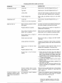
TROUBLESHOOTING
GUIDE
PERFORMING REPAIRS MAY EXPOSE VOLTAGE SOURCES_ MOVING PARTS_ OR COMPRESSED
A_R SOURCES PERSONAL _NJURY MAY OCCUR. PRIOR TO ATTE_IPT_NG ANY REPAIRS THE
COMPRESSOR MUST BE UNPLUGGED, AND A_R TANK PRESSURE REUEVED° NEVER OPERATE
THE UNiT W_TN THE BELT GUARD REMOVED°
PROBLEM
CAUSE
CORRECTION
Excessive tank pressure safety valve pops off.
Pressure switch does not shut off
motor when compressor reaches
"cut-out" pressure.
Move the pressure switch lever to the "OFF" position. If the outfit doesn't shut off, and the ebctricai
contacts are welded together, replace the pressure
switch.
If the contacts are good, check to see if the pin in
the bottom of the pressure retief vane is stuck, if it
does not move freely, reptace the valve.
Pressure
high.
Air leaks at fittings
switch
"cut-out"
too
Return the outfit to the Sears Service Center to
check and adjust or replace switch.
"Tubefittings are not tight enough.
Tighten fittings where air can be heard escaping.
Check fittings with soapy water solution. DO NOT
OVER-TIGHTEN.
TROUBLESHOOTING
GUIDE (continued)
PROBLEM
CAUSE
CORRECTION
Air leaks at check valve
Defective or dirty check valve.
A defective check valve results in a constant air
teak at the pressure reiease valve when there is
pressure in the tank and the compressor is shut off.
Remove and clean, OFreplace check valve. DO
NOT OVER-TiGHTEN.
Air leaks at pressure
switch release valve
Defective
pressure
release valve.
Remove and replace the release valve.
Air leaks in air tank
switch
Defective check valve.
A defective check valve results in a constant air
leak at the pressure release valve when there is
pressure in the tank and the compressor is shut off.
Remove and clean, or replace check valve. DO
NOT OVER-TIGHTEN.
Defective air tank.
Air tank must be replaced. Do not repair the leak.
DO NOT DRILL mNTO, WELD, OR OTHERW_SE MODIFY AIR TANK OR mT WILL
WEAKEN.
Air leaks from safety valve
Possible defect in safety valve
Operate safety valve manually by pulling on ring. ff
valve still leaks, it should be replaced.
Regulator knob - continuous air leak. Regulator will
not shut-off at air outlet.
Dirty or damaged regulator internat parts.
Clean or replace regulator, or internal parts.
Knocking noise
Defective check valve.
Remove and clean, or replace.
Loose pulley.
Tighten pulley set screw, (70-80 In.-Lbs.).
Low oil level.
Maintain prescribed oil level. Add oil
Loose flywheel.
Tighten screw. 15 to 20 ft. lbs.
Loose compressor
screws.
Compressor is not supplying enough air to operate
accessories.
2
mounting
Check screws. Tighten as required, (15-20 Ft.Lbs.).
Loose belt.
Tighten wing nut on motor mount until it contacts
the washer, plus one more turn.
Carbon build up.
Remove the head and valve plate. Clean the valve
plate and the top of the piston. (Be sure carbon
does not fall into the cylinder.) Reassemble using
new gaskets and torque screws, 25 to 30 ft. Ibs.
Prolonged excessive use of air.
Decrease amount of air usage.
Compressor is not large enough
for air requirement.
Check the accessory air requirement, ff it is higher
than the SCFM or pressure supplied by your air
compressor, you need a larger compressor.
Restricted air intake filter.
Clean or replace air intake filter. Do not operate the
compressor in the paint spray or sand blasting
area.
Hole in hose.
Check and replace.
Check valve restricted.
Remove and ctean, or replace.
Air leaks.
Tighten
fittings.
(See Air Leaks
Troubleshooting Guide, Pg. tl.)
section
of
TROUBLESHOOTING
GUIDE (continued)
PROBLEM
CAUSE
CORRECTION
Excessive belt wear
Loose belt,
Adjust tension. See Belt Replacement, pg, 11.
Tight belt.
Adjust tension. See Belt Replacement, pg. 11.
Loose pulley_
Check for worn keyway or pulley bore. Also check
for bent motor shaft. Replace parts if necessary.
Pulley misalignment.
Motor pulley
1/32".
Loose
Adjust tension.
Squealing
sound
Motor wilt not run
Pressure reading on the
regulated pressure gauge
drops when an accessory is
used.
belt.
and flywheel
must be in line within
See Belt Replacement,
pg. 11.
There is no oii in the compressor.
Add oi!.
Motor overload
has tripped,
Let motor cool off end reset switch by pressing
red button located on the end of the motor.
protection
switch
the
Possible defective capacitor.
Return to Sears Service Center for inspection or
replacement if necessary.
Tank pressure exceeds pressure
switch "cut-in" pressure.
Motor will start automatically when tank pressure
drops below "cut-in" pressure of pressure switch.
Wrong gauge wire or length of
extension cord,
Check for proper gauge wire and cord length.
Check valve stuck open.
Remove and clean, or replace. DO NOT OVERTIGHTEN.
Loose electrical connections.
Unplug the compressor. Check wiring connection
inside pressure switch and motor terminal box
area.
Paint spray
parts.
Have checked at Sears Service Center. Do not
operate the compressor in the spray area.
on internal
motor
Possible defective motor.
Have checked at a local Sears Service Center.
Fuse blown,
tripped.
1. Check fuse box for blown fuse and replace if
necessary. Re-set circuit breaker. Do not use a
fuse or circuit breaker with higher rating than
that specified for your particular branch circuit.
2. Check for proper fuse; onty Buss Fusetron Type
"T" fuses are acceptable.
3. Check for low voltage conditions and/or proper
extension cord.
4. Remove check valve and clean or replace if it is
stuck open or closed.
5. Disconnect the other electrical appliances from
circuit or operate the compressor on its own
branch circuit.
circuit
breaker
Pressure release valve on pressure switch has not unloaded
head pressure,
Bleed the line by pushing the lever on the pressure
switch to the "OFF" position; if valve does not
open, replace it.
It is normal for "some" pressure
drop to occur,
If there is an excessive amount of pressure drop
when the accessory is used, adjust the regulator
following the instructions on pg. 6.
Note
Adjust the regulated pressure under flow
conditions (while the accessory is being
used).
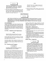
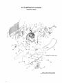
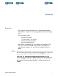
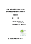
AIR COMPRESSOR
DtAGRAM
(view from back}
2
I7
14
12
55
54
\
53
52
"58
!8
34
51A
_J
5O
35
48
(Model No. shown here)
"43
\
42
4!
(See pg. 8, Step 2 for proper
wheel placement and assembly)
14
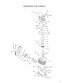
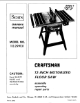
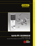
COMPRESSOR
PUMP D_AGRAM
89
82
(od "Ill p ugl
83
/
/
/
_o_,dra,n plug}
_5
r
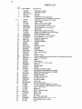
PARTS LiST
KEY
NO
f
2
3
4
5
6
7
8
9
10
11
12
13
14
15
16
17
18
t 9
20
21
22
23
24
25
26
27
28
28A
29
30
31
32
33
34
35
36
37
38
39
40
41
42
43
44
45
45
47
48
49
50
51
5t A
52
53
54
PART NUMBER
CAC=322
CAC_323
SSF-8113-ZN
CAC-327
CACo4OG3-1
9=16279
265-18
SSF-935
LA-1779
STD575051
STD575050
CAC-317
TIA-4325
TIA-4125
C-GA-345
STD575026
STD575025
CAC-387
CAC-1012
CAC-4296
H-2099
SS-2071
CAC-1913
SSo3222-CD
CAC-366
SUDL-403-1
SSW-7367
LA-1531-1
CAC=4220-1
KK-4315
CAC=4215-1
SS=1287
CAC=437
SSF-928
STD54163t
LA-1535
CACo320
LA-1814
LA-1932-2
LA-1933
CAC-1059
SUDL-6=I
CAC=60
CAC-4293
STD541437
SS-2797
Not Available
TA_4099
TA=4072
LA-1555
CAC-287
LA-181 f-1
MO=8340
C-PU-2885
SS-391
LA=f 978
STD580104
SSF=986
LA=1931
DESCRIPTION
Belt guard, outside
Belt guard, inside
Lock nut
Bracket
Compressor pump assembly
includes Key No. 59 through 93 inclusive.
intake filter - package of 2 (1 used)
Filter retainer
Screw, #8-32 x 3/8" (2 used)
Hot Surface Labem(2 used)
Ferrule (2 used for 1/2" O.D. Tube)
Nut (2 used for 1/2" O.D. Tube)
Outlet tube
Safety valve (model 919.176730)
Safety valve ASME (model 919.17683D)
Pressure gauge (2 used)
Ferrule (2 used for 1/4" O.D. Tube)
Nut (2 used for 1/4" O.D. Tube)
Pressure release tube
Hold down p|ate
Pressure regulator
Adapter
Nipple
Held down screw
Pipe plug
Manifold
Cord assembty
Strain relief (2 used)
Label
Pressure switch
Pressure release valve and mounting nut (included with #28)
Motor cord assembly
Nipple
Check valve
Screw 5/16"-18 × 7/8" (4 used)
Wing nut
Warning labe_
Handle
Periodic maintenance mabel
Specification label (Model 919.176730)
Specification |abel (Model 919.176830)
Retaining clip (2 used)
Rubber foot strip
Shoulder bolt (2 used)
8" wheel (2 used)
Lock nut (2 used)
Drain cock
Code number label
Air tank, 20 gallon (Modei 919.176730)
Air tank, 26 gallonASME (Model 919.176630)
Labe_- 12gV wired
Motor pin
Sears Craftsman mabeJ
Motor, 3 HP
Motor pulley
Set screw
Drain Tank Daily LabeB
Motor shaft key (3/16" × 3/16" × 1¼")
Self-t_pping screw (2 used)
Label
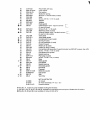
55
56
57
58
59
60
61
62
($3
_/ 84
O 65
66
67
68
69
70
71
,Q=72
,_ 73
74
75
76
77
78
79
80
81
82
83
84
85
88
87
88
89
90
91
92
93
C-BT-222
SSN°1619oZN
SSN=56=ZN
CAC-1011
SSFo6627
CAC-293
SSF-955
SS=8553
SSP=940t
CAC=291
265-25
Pomy=V=Belt, 38" long
Lock washer
Fiat washer
CA0-289
CAC-54_1
CAC-56
CAC-58
CAC=57
CAC-55
265ol 9
CAC=207
265o410
SSF-927
CAC-51
265=41
SSP-1413
SSF=925
265-3
265-16
CAC=373
265-23
265-13
265-9
265=2
SSN=1014=ZN
STD523107
265=11 t
265=5
E_aetomer spring
Stud 3/8" × 36 both ends (2 used}
Head
Screw, 3/8"=16 × 1=1/2" t4 used)
Adapter
Adapter
Head gasket
intake flapper valve = squcre corners
I
(2 used on head)
Screw #5=40 × %" (8 used)
Restrictor
plate f2 used)
E×hcust fgspper valve o beveled corners
I_
(2 used on veJve p_ate)
Valve plate
Valve plate gasket
Compression
ring (4 used)
Oi_ ring (4 used)
OiJ ring expsnder
(2 used)
Piston (2 used)
Piston pin (2 used)
Piston pin plug (4 used)
Connecting
rod aasembty (2 used) includes two SSFo927 screws,
Screw, 1/4"-20 x %t/8" !4 used)
Crankcase
and cyiinder
Needle bearing
Pipe pmug (2 used)
Screw, 1/4"-20 x 7/8" (] 2 oaed)
Base
Base gasket
Crankshaft
Needle bearing
End ptate gasket
End PIste
Flywheel
BelleviHe washer
Cap screw
Seal
Vent filter
9-16259
9-16153
SI-30_14o4-D
NOTmLLUSTRATED
Airchuck
Airhose assembly(1/4"LD.×15')
Owners manuat
SSF-9821
CACo294
265=196
_= Key No. 71, 72 and 73, only available in Ring Kit KK-4313
J Key No. 6, 84, 70, 84, 87, 92 and 93, available as individuaD
O Key No. 65, 65 and 68, on{y svaitabJe in Veive Kit KK-4275.
Key #78.
parts end part of Gasket Kit KK=4312-2_
OWNERS
MANUAL
SERVICE
MODEL NO.
919.176730
919.176830
HOW TO ORDER
REPAIR PARTS
CRAFTSMAN AIR COMPRESSOR
Now that you have purchased your Sears Air Compressor, should a
need ever exist for repair parts or service, simply contact any Sears
Service Center and most Sears, Roebuck and Co. stores. Be sure
to provide all pertinent facts when you call or visit.
The model number of your Sears Air Compressor is 919
This number can be found on the maintenance label which is
located on the rear of the air tank.
WHEN ORDERING REPAIR PARTS, ALWAYS GIVE THE
FOLLOWING INFORMATION:
• PART NUMBER
• PART DESCRIPTION
, MODEL NUMBER
• NAME OF ITEM
If service or repair parts are required for the motor, supply all motor
nameplate information including manufacturers name.
All parts listed may be ordered from any Sears Service Center and
most Sears stores.
If the parts you need are not stocked locally, your order will be electronically transmitted to a Sears Repair Parts Distribution Center for
handling.
Sears,
SI-30-14-4-D
6/89
Roebuck
and
Co., Chicago,
_L 60684
U.SoAo
Printed in U.S.A,