1
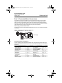
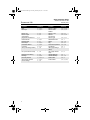
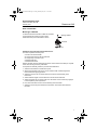
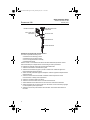
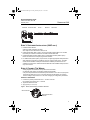
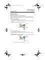
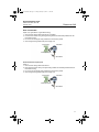
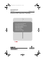
00825-0100-4825.fm Page 1 Friday, February 18, 2011 11:49 AM Quick Installation Guide 00825-0100-4825, Rev DB February 2011 Rosemount 248 Rosemount 248 Temperature Transmitter Start Step 1: Configure (Bench Calibration) Step 2: Mount the Transmitter Step 3: Software Installation (248C only) Step 4: Connect the Wiring Step 5: Perform a Loop Test Product Certifications 248C License Agreement EC Declaration of Conformity End www.rosemount.com ¢00825-0100-4825e¤ 00825-0100-4825.fm Page 2 Friday, February 18, 2011 11:49 AM Quick Installation Guide 00825-0100-4825, Rev DB February 2011 Rosemount 248 © 2011 Rosemount Inc. All rights reserved. All marks property of owner. The Emerson logo is a trade mark and service mark of Emerson Electric Co. Rosemount and Rosemount logotype are registered trademarks of Rosemount Inc. HART is a registered trademark of the HART Communications Foundation. Emerson Process Management Rosemount Division 8200 Market Boulevard Chanhassen, MN USA 55317 T (US) (800) 999-9307 T (Intnl) (952) 906-8888 F (952) 949-7001 Emerson Process Management Emerson Process Management Shared Services Ltd. Asia Pacific Private Limited Heath Place West Sussex P022 9 SH England T 44 (1234) 868 121 F 44 (1234) 867 554 1 Pandan Crescent Singapore 128461 T (65) 6777 8211 F (65) 6777 0947 IMPORTANT NOTICE This installation guide provides basic guidelines for the Rosemount® 248. It does not provide instructions for detailed configuration, diagnostics, maintenance, service, troubleshooting, or installations. Refer to the Rosemount 248 reference manual (document number 00809-0100-4825) for more instruction. The manual and this QIG are also available electronically on www.rosemount.com. WARNING Explosions could result in death or serious injury: Installation of this transmitter in an explosive environment must be in accordance with the appropriate local, national, and international standards, codes, and practices. Please review the Hazardous Locations Certifications for any restrictions associated with a safe installation. In an Explosion-proof/Flame-proof installation, do not remove the transmitter covers when power is applied to the unit. Process leaks may cause harm or result in death • Install and tighten thermowells or sensors before applying pressure. • Do not remove the thermowell while in operation. Electrical shock can result in death or serious injury • Avoid contact with the leads and terminals. High voltage that may be present on leads can cause electrical shock. 2 00825-0100-4825.fm Page 3 Friday, February 18, 2011 11:49 AM Quick Installation Guide 00825-0100-4825, Rev DB February 2011 Rosemount 248 STEP 1: CONFIGURE (BENCH CALIBRATION) The Rosemount 248 communicates using the 375 Field Communicator (communication requires a loop resistance between 250 and 1100 ohms. Do not operate when power is below 12Vdc at the transmitter terminal). Refer to the Rosemount 248 Reference Manual (document number 00809-0100-4825) and the 375 Field Communicator Reference Manual (http://www.fieldcommunicator.com/suppmanu.htm) for more information. Connecting a Field Communicator The Hand-held Communicator Field Device Revision Dev v1, DD v1 is required for complete functionality. Figure 1. Connecting a Communicator to a Bench Loop Rosemount 248 Transmitter 250 RL 1100 Power Supply Field Communicator Verify Transmitter Configuration To verify operation using a Field Communicator, refer to the Fast Keys below. Refer to the Rosemount 248 Reference Manual (document number 00809-0100-4825) for more detailed description. Function Fast Keys Function Fast Key Active Calibrator Alarm/Saturation AO Alarm Type Burst Mode Burst Option Calibration Configuration D/A Trim Damping Values 1, 2, 2, 1, 3 1, 3, 3, 2 1, 3, 3, 2, 1 1, 3, 3, 3, 3 1, 3, 3, 3, 4 1, 2, 2 1, 3 1, 2, 2, 2 1, 1, 10 Poll Address Process Temperature Process Variables PV Damping PV Unit Range Values Review Scaled D/A Trim Sensor Connection 1, 3, 3, 3, 1 1, 1 1, 1 1, 3, 3, 1, 3 1, 3, 3, 1, 4 1, 3, 3, 1 1, 4 1, 2, 2, 3 1, 3, 2, 1, 1 3 00825-0100-4825.fm Page 4 Friday, February 18, 2011 11:49 AM Quick Installation Guide 00825-0100-4825, Rev DB February 2011 Rosemount 248 4 Function Fast Keys Function Fast Key Date Descriptor 1, 3, 4, 2 1, 3, 4, 3 1, 3, 2, 1, 2 1, 3, 2, 1, 3 Device Info Device Output Configuration Diagnostics and Service Filter 50/60 Hz Hardware Rev Hart Output Intermittent Detect Loop Test LRV (Lower Range Value) 1, 3, 4 1, 3, 3 1, 2 1, 3, 5, 1 1, 4, 1 1, 3, 3, 3 1, 3, 5, 4 1, 2, 1, 1 1, 1, 6 LSL (Lower Sensor Limit) 1, 1, 8 Measurement Filtering Message Num Req Preams Open Sensor Holdoff Percent Range 1, 3, 5 1, 3, 4, 4 1, 3, 3, 3, 2 1, 3, 5, 3 1, 1, 5 Sensor 1 Setup Sensor Serial Number Sensor 1 Trim Sensor 1 Trim-Factory Sensor Type Software Revision Status Tag Terminal Temperature Test Device URV (Upper Range Value) USL (Upper Sensor Limit) Variable Mapping Variable Re-Map Write Protect 2-Wire Offset 1, 2, 2, 1 1, 2, 2, 1, 2 1, 3, 2, 1, 1 1, 4, 1 1, 2, 1, 4 1, 3, 4, 1 1, 3, 2, 2, 1, 2, 1 1, 1, 7 1, 1, 9 1, 3, 1 1, 3, 1, 3 1, 2, 3 1, 3, 2, 1, 2, 1 00825-0100-4825.fm Page 5 Friday, February 18, 2011 11:49 AM Quick Installation Guide 00825-0100-4825, Rev DB February 2011 Rosemount 248 STEP 2: MOUNT THE TRANSMITTER Mount the transmitter at a high point in the conduit run to prevent moisture from draining into the transmitter housing. Typical European and Asia Pacific Installation Head Mount Transmitter with DIN Plate Style Sensor 1. Attach the thermowell to the pipe or process container wall. Install and tighten the thermowell before applying process pressure. 2. Assemble the transmitter to the sensor. Push the transmitter mounting screws through the sensor mounting plate and insert the snap rings (optional) into the transmitter mounting screw groove. 3. Wire the sensor to the transmitter. 4. Insert the transmitter-sensor assembly into the connection head. Thread the transmitter mounting screw into the connection head mounting holes. Assemble the extension to the connection head. Insert the assembly into the thermowell. 5. Slip the shielded cable though the cable gland 6. Attach a cable gland into the shielded cable. 7. Insert the shielded cable leads into the connection head through the cable entry. Connect and tighten the cable gland. 8. Connect the shielded power cable leads to the transmitter power terminals. Avoid contact with sensor leads and sensor connections. 9. Install and tighten the connection head cover. Enclosure covers must be fully engaged to meet explosion-proof requirements. B A C D E F A = Rosemount 248 Transmitter D = Transmitter Mounting Screws B = Connection Head E = Integral Mount Sensor with Flying Leads C = Thermowell F = Extension 5 00825-0100-4825.fm Page 6 Friday, February 18, 2011 11:49 AM Quick Installation Guide 00825-0100-4825, Rev DB February 2011 Rosemount 248 STEP 2 CONTINUED... Typical North and South American Installation Head Mount Transmitter with Threaded Sensor 1. Attach the thermowell to the pipe or process container wall. Install and tighten thermowells before applying process pressure. 2. Attach necessary extension nipples and adapters to the thermowell. Seal the nipple and adapter threads with silicone tape. 3. Screw the sensor into the thermowell. Install drain seals if required for severe environments or to satisfy code requirements. 4. Pull the sensor wiring leads through the universal head and transmitter. Mount the transmitter in the universal head by threading the transmitter mounting screws into the universal head mounting holes. 5. Mount the transmitter-sensor assembly into the thermowell. Seal adapter threads with silicone tape. 6. Install conduit for field wiring to the conduit entry of the universal head. Seal conduit threads with silicone tape. 7. Pull the field wiring leads through the conduit into the universal head. Attach the sensor and power leads to the transmitter. Avoid contact with other terminals. 8. Install and tighten the universal head cover. Enclosure covers must be fully engaged to meet explosion-proof requirements. A D B C E A = Threaded Thermowell B = Threaded Style Sensor C = Standard Extension 6 D = Universal Head E = Conduit Entry 00825-0100-4825.fm Page 7 Friday, February 18, 2011 11:49 AM Quick Installation Guide 00825-0100-4825, Rev DB February 2011 Rosemount 248 STEP 2 CONTINUED... Mounting to a DIN Rail To attach the Rosemount 248H to a DIN rail, assemble the appropriate rail mounting kit (part number 00248-1601-0001) to the transmitter as shown. Mounting Hardware Transmitter Rail Clip Rail Mount Transmitter with Remote Mount Sensor The least complicated assembly uses: • a remote mounted transmitter • an integral mount sensor with terminal block • an integral style connection head • a standard extension • a threaded thermowell Refer to the Metric Product Data Sheet (document number 00813-0101-2654) for complete sensor and mounting accessory information. To complete the assembly, follow the procedure described below. 1. Attach the transmitter to a suitable rail or panel. 2. attach the thermowell to the pipe or process container wall. Install and tighten the thermowell before applying pressure. 3. Attach the sensor to the connection head and mount the entire assembly to the thermowell. 4. Attach sufficient lengths of sensor lead wire to the sensor terminal block. 5. Attach and tighten the connection head cover. Enclosure covers must be fully engaged to meet explosion-proof requirements. 6. Run sensor lead wires from the sensor assembly to the transmitter. 7. Attach the sensor and power leads to the transmitter. Avoid contact with leads and terminals. 7 00825-0100-4825.fm Page 8 Friday, February 18, 2011 11:49 AM Quick Installation Guide 00825-0100-4825, Rev DB February 2011 Rosemount 248 Rail Mount Transmitter Sensor Leads with Cable Gland Integral Mount Sensor with Terminal Block Connection Head Standard Extension Threaded Thermowell Rail Mount Transmitter with Threaded Sensor The least complicated assembly uses: • a threaded sensor with flying heads • a threaded sensor connection head • a union and nipple extension assembly • a threaded thermowell Refer to Volume 1 of the Rosemount Sensors Product Data Sheet (document number 00813-0100-2654) for complete sensor and mounting accessory information. To complete the assembly, follow the procedure described below. 1. Attach the transmitter to a suitable rail or panel. 2. Attach the thermowell to the pipe or process container wall. Install and tighten the thermowell before applying pressure. 3. Attach necessary extension nipples and adaptors. Seal the nipple and adapter threads with silicone tape. 4. Screw the sensor into the thermowell. Install drain seals if required for severe environments or to satisfy code requirements. 5. Screw the connection head to the sensor. 6. Attach the sensor lead wires to the connection head terminals. 7. Attach additional sensor lead wires from the connection head to the transmitter. 8. Attach and tighten the connection head cover. Enclosure covers must be fully engaged to meet explosion-proof requirements. 9. Attach the sensor and power leads to the transmitter. Avoid contact with leads and terminals. 8 00825-0100-4825.fm Page 9 Friday, February 18, 2011 11:49 AM Quick Installation Guide 00825-0100-4825, Rev DB February 2011 Rosemount 248 Rail Mount Threaded Sensor Threaded Style Transmitter Connection Head Sensor Standard Extension Threaded Thermowell STEP 3: SOFTWARE INSTALLATION (248C ONLY) 1. Install the 248C software • Place the 248C CD-ROM in the drive • Run setup.exe from Windows NT, 2000, or XP 2. HART interface Box (248C1 option): Connect the HART Interface Box to PC and 248 transmitter per instructions located on the HART Interface Box label 3. Install Serial HART modem (248C2 option) or USB HART modem (248C3 option). Please see instructions accompanying modem hardware. 4. For USB modem (248C3 option): Upon first use, configure appropriate COM ports within 248C software by selecting “Port Settings” from the “Communicate” menu. The USB modem driver emulates a COM port and will add to available port selections in the software’s drop-down box. Otherwise software defaults to first available COM port, which may not be correct. STEP 4: CONNECT THE WIRING • Wiring diagrams are located on the top label of the transmitter. • An external power supply is required to operate the transmitter. • The power required across the transmitter power terminals is 12 to 42.4 V dc (the power terminals are rated to 42.4 V dc). To prevent damaging the transmitter, do not allow terminal voltage to drop below 12.0 V dc when changing the configuration parameters. Power the Transmitter 1. Connect the positive power lead to the “+” terminal. Connect the negative power lead to the “–” terminal. 2. Tighten the terminal screws. 3. Apply power (12 – 42 V dc). Figure 2. Power, Communication, and Sensor Terminals Sensor Terminals _ + Power/Communication Terminals 9 00825-0100-4825.fm Page 10 Friday, February 18, 2011 11:49 AM Quick Installation Guide 00825-0100-4825, Rev DB February 2011 Rosemount 248 STEP 4 CONTINUED... Ground the Transmitter Ungrounded Thermocouple, mV, and RTD/Ohm Inputs Each process installation has different requirements for grounding. Use the grounding options recommended by the facility for the specific sensor type, or begin with grounding Option 1 (the most common). Option 1 (for grounded housing): 1. Connect sensor wiring shield to the transmitter housing. 2. Ensure the sensor shield is electrically isolated from surrounding fixtures that may be grounded. 3. Ground signal wiring shield at the power supply end. 4–20 mA loop Shield ground point Transmitter Sensor Wires Option 2 (for ungrounded housing): 1. Connect signal wiring shield to the sensor wiring shield. 2. Ensure the two shields are tied together and electrically isolated from the transmitter housing. 3. Ground shield at the power supply end only. Ensure that the sensor shield is electrically isolated from the surrounding grounded fixtures. 4–20 mA loop Transmitter Shield ground point Sensor Wires Connect shields together, electrically isolated from the transmitter 10 00825-0100-4825.fm Page 11 Friday, February 18, 2011 11:49 AM Quick Installation Guide 00825-0100-4825, Rev DB February 2011 Rosemount 248 STEP 4 CONTINUED... Option 3 (for grounded or ungrounded housing): 1. Ground sensor wiring shield at the sensor, if possible. 2. Insure that the sensor wiring and signal wiring shields are electrically isolated from the transmitter housing. 3. Do not connect the signal wiring shield to the sensor wiring shield. 4. Ground signal wiring shield at the power supply end. 4–20 mA loop Transmitter Shield ground point Sensor Wires Grounded Thermocouple Inputs Option 4 1. Ground sensor wiring shield at the sensor. 2. Ensure that the sensor wiring and signal wiring shields are electrically isolated from the transmitter housing. 3. Do not connect the signal wiring shield to the sensor wiring shield. 4. Ground signal wiring shield at the power supply end. 4–20 mA loop Transmitter Shield ground point Sensor Wires 11 00825-0100-4825.fm Page 12 Friday, February 18, 2011 11:49 AM Quick Installation Guide Rosemount 248 00825-0100-4825, Rev DB February 2011 STEP 5: PERFORM A LOOP TEST The Loop Test command verifies transmitter output, loop integrity, and operation of any recorders or similar devices installed in the loop. NOTE: This is not available with the 248C Configuration Interface. Initiate a loop test: 1. Connect an external ampere meter in series with the transmitter loop (so the power to the transmitter goes through the meter at some point in the loop. 2. From the home screen select 1) Device Setup, 2) Diag/Serv, 1) Test Device, 1) Loop Test. 3. Select a discrete milliampere level for the transmitter to output. At Choose Analog Output select 1) 4mA, 2) 20mA or select 3) Other to manually input a value between 4 and 20 milliamperes. Select Enter to show the fixed output. Select OK. 4. In the test loop, check that the fixed mA input and the transmitter’s mA output are the same value. If the readings do not match, either the transmitter requires an output trim or the current meter is malfunctioning. After completing the test, the display returns to the loop test screen and allows the user to choose another output value. To end the Loop Test, Select 5) End and Enter. 12 00825-0100-4825.fm Page 13 Friday, February 18, 2011 11:49 AM Quick Installation Guide 00825-0100-4825, Rev DB February 2011 Rosemount 248 PRODUCT CERTIFICATIONS Approved Manufacturing Locations Rosemount Inc. – Chanhassen, Minnesota, USA Rosemount Temperature GmbH – Germany Emerson Process Management Asia Pacific – Singapore European Union Directive Information The EC declaration of conformity for all applicable European directives for this product can be found on the Rosemount website at www.rosemount.com. A hard copy may be obtained by contacting our local sales representative. ATEX Directive (94/9/EC) Rosemount Inc. complies with the ATEX Directive. Electro Magnetic Compatibility (EMC) (89/336/EEC) All Models: EN 50081-1: 1992; EN 50082-2:1995; EN 61326-1:1997 – Industrial NAMUR NE21 Recommendations The Rosemount 248 meets the requirements for NAMUR NE21 Rating Susceptibility Parameter Influence ESD • 6 kV contact discharge • 8 kV air discharge None Radiated • 80 – 1000 MHz at 10 V/m AM None Burst • 1 kV for I.O. None Surge • 0.5 kV line–line • 1 kV line–ground (I.O. tool) None Conducted • 150 kHz to 80 MHz at 10 V None CE Mark The Rosemount 248 meets all requirements listed under IEC 61326:Amendment 1, 1998 13 00825-0100-4825.fm Page 14 Friday, February 18, 2011 11:49 AM Quick Installation Guide 00825-0100-4825, Rev DB February 2011 Rosemount 248 Hazardous Locations Certifications(1) North American Certifications Factory Mutual (FM) I5 FM Intrinsic Safety and Non-incendive Intrinsically Safe for Class I/II/III, Division 1, Groups A, B, C, D, E, F, and G. Non-incendive Field Circuit for Class I, Division 2, Groups A, B, C, and D. Intrinsically Safe and non-incendive when installed in accordance with Rosemount drawing 00248-1055. Temperature Codes: T5 (Tamb = –50 to 75 °C) T6 (Tamb = –50 to 40 °C) Table 1. Entity Parameters Loop/Power Sensor Ui = 30 Vdc Ii = 130 mA Pi = 1.0 W Ci = 3.6 nF Li = 13.8 H Uo = 45 Vdc Io = 26 mA Po = 290 mW Co = 0.4 nF Lo = 49.2 mH E5 FM Explosion-Proof Explosion-Proof for Class I, Division 1, Groups B, C, and D. Dust Ignition Proof for Class II/III, Division 1, Groups E, F, G when installed in accordance with Rosemount drawing 00644-1049. Temperature Codes: T5 (Tamb = –40 to 85 °C) Combination Certifications K5 Combination of I5 and E5. Canadian Standards Association (CSA) Approvals I6 CSA Intrinsically Safe and Class I, Division 2 Intrinsically Safe for Class I, Division 1, Groups A, B, C, and D when installed in accordance with Rosemount drawing 00248-1056. Temperature Codes: T5 (Tamb = –50 to 60 °C) T6 (Tamb = –50 to 40 °C) Suitable for use in Class I, Division 2, Groups A, B, C, and D. K6 CSA Intrinsically Safe, Explosion-Proof, and Class I, Division 2. Combination of I6 and Explosion-Proof for Class I, Division 1, Groups B, C, and D; Class II, Division 1, Groups E, F, and G; Class III, Division 1 hazardous locations, when installed in accordance with Rosemount drawing 00644-1059. Suitable for Class I, Division 2, Groups A,B, C, and D. Ambient Temperature Limit: –50 to 85°C (1) Consult factory for availability. 14 00825-0100-4825.fm Page 15 Friday, February 18, 2011 11:49 AM Quick Installation Guide 00825-0100-4825, Rev DB February 2011 Rosemount 248 European Certifications CENELEC Approvals I1 CENELEC Intrinsic Safety Certificate Number: Baseefa03ATEX0030X ATEX Marking: II 1 G 1180 Ex ia IIC Temperature Codes: T5 (–60 Tamb 80 °C) T6 (–60 Tamb 60 °C) Table 2. Entity Parameters Loop/Power Sensor Ui = 30 Vdc Ii = 130 mA Pi = 1.0 W Ci = 3.6 nF Li = 0 Uo = 45 Vdc Io = 26 mA Po = 290 mW Ci = 2.1 nF Li = 0 Special Conditions for Safe Use (X): The apparatus must be installed in an enclosure which affords it a degree of protection of at least IP20. Non-metallic enclosures must have a surface resistance of less than 1 GOHM; light alloy or zirconium enclosures must be protected from impact and friction when installed. E1 CENELEC Flame-Proof Approval Certificate Number: KEMA99ATEX8715X ATEX Marking: II 2 G 1180 Ex d IIC Table 3. Entity Parameters Umax = 42.4 Vdc Umax = 24 mA Temperature Codes: T6 (–50 Tamb 65 °C) Special Conditions for Safe Use (X): For information on the dimensions of the flameproof joints, the manufacturer shall be contacted. N1 CENELEC Type n Certificate Number: BAS00ATEX3145 ATEX Marking: II 3G Ex nL IIC Table 4. CENELEC Input Parameters Umax = 45 V Temperature Codes: T5 (–40 Tamb 70 °C) 15 00825-0100-4825.fm Page 16 Friday, February 18, 2011 11:49 AM Quick Installation Guide 00825-0100-4825, Rev DB February 2011 Rosemount 248 NC CENELEC Type n Component Certificate Number: Baseefa03ATEX0032U ATEX Marking: II 3G Ex nA IIC Table 5. CENELEC Input Parameters Ui = 42.4 V Ci = 3.6nF Li = 0 Temperature Codes: T5 (–60 Tamb 80°C) T6 (–60 Tamb 60°C) IECEx Certifications I7 IECEx Intrinsic Safety Certificate Number: IECEx BAS 07.0086X Ex ia IIC T5 (-60°C ≤ Ta ≤ +80°C) Ex ia IIC T6 (-60°C ≤ Ta ≤ +60°C) Special Conditions for Safe Use (X): The apparatus must be installed in an enclosure which affords it a degree of protection of at least IP20. Non-metallic enclosures must have a surface resistance of less than 1GΩ; light alloy or zirconium enclosures must be protected from impact and friction when installed. Table 6. Entity Parameters Loop / Power Ui = 30 Vdc Ii = 130 mA Pi = 1.0 W Ci = 3.63 nF Li = 0 mH Sensor Uo = 45 Vdc Io = 26 mA Po = 290 mW Ci = 2.1 nF Li = 0 E7 IECEx Flameproof and Dust Certificate No.: IECEx KEM 09.0015X Ex d IIC T6 (Flameproof) Ex tD A20 IP 66 T 95 ºC (Dust) Vmax = 42.4V Special Conditions for Safe Use (X): For information on the dimensions of the flameproof joints the manufacturer shall be contacted. Table 7. Electrical Data Transmitter Umax = 42.4 Vdc Imax = 24.0 mA 16 Sensor Umax = 5 V Imax = 2.0 mA 00825-0100-4825.fm Page 17 Friday, February 18, 2011 11:49 AM Quick Installation Guide 00825-0100-4825, Rev DB February 2011 Rosemount 248 N7 IECEx Type n Certificate Number: IECEx BAS 07.0055 Ex nA nL IIC T5 (-40 °C < Ta < 70 °C) Table 8. Electrical Data Transmitter Ui = 42.4 V RTD Ui = 5 V Sensor Thermocouple Ui = 0 NG IECEx Type n Component Certificate Number: IECEx BAS 08.0087U Ex nA IIC T5 (-60°C ≤ Ta ≤ +80°C) Ex nA IIC T6 (-60°C ≤ Ta ≤ +60°C) Input Parameter: Ui = 42.4 Vdc Schedule of Limitations: The component must be housed in a suitably certified enclosure that provides a degree of protection of at least IP54. Brazilian Certifications Centro de Pesquisas de Energia Eletrica (CEPEL) Approval I2 CEPEL Intrinsic Safety Japanese Certifications Japanese Industrial Standard (JIS) Approvals I4 JIS Intrinsic Safety E4 JIS Explosion-Proof 17 00825-0100-4825.fm Page 18 Friday, February 18, 2011 11:49 AM Quick Installation Guide 00825-0100-4825, Rev DB February 2011 Rosemount 248 248C License Agreement ★ Applicable to 248C PC Programming Interface Only THIS IS A LEGAL AGREEMENT BETWEEN YOU (LICENSEE) AND ROSEMOUNT INC.BY LOADING THIS SOFTWARE INTO A COMPUTER, YOU ARE AGREEING TO THE TERMS OF THIS AGREEMENT. IF YOU DO NOT AGREE TO THE TERMS OF THIS AGREEMENT, DO NOT LOAD THIS SOFTWARE INTO YOUR COMPUTER. PROMPTLY RETURN THE ENTIRE SOFTWARE PACKAGE AND RELATED DOCUMENTATION TO WHERE YOU OBTAINED THEM FOR A FULL REFUND. LICENSEE ACKNOWLEDGES BY USING THIS SOFTWARE THAT LICENSEE HAS READ THIS AGREEMENT, UNDERSTANDS IT, AND THAT THIS AGREEMENT CONSTITUTES THE ENTIRE AGREEMENT AND UNDERSTANDING AND CONTAINS ALL TERMS AND REPRESENTATIONS, EXPRESS, OR IMPLIED, BETWEEN LICENSEE AND ROSEMOUNT INC. WITH RESPECT TO THE SOFTWARE AND DOCUMENTATION. GRANT OF LICENSE: In consideration of normal License fees paid by Licensee, Rosemount Inc. grants, and Licensee accepts, a non-transferable, non-exclusive license to use THE SOFTWARE in object code only and any of its Documentation on a single computer. For an additional fee, Licensee may purchase a site license entitling Licensee to use the Software on multiple computers at the same time. Licensee shall use the software in object code form only and solely for licensees own internal data processing. RESPONSIBILITIES OF LICENSEE: Licensee shall be exclusively responsible for the supervision, management and use of the Software and Documentation. Licensee agrees to implement sufficient security measures to protect the Rosemount Inc. propriety interest in the Software and Documentation. Licensee further agrees to include the appropriate copyright or proprietary notice, in the same manner and style utilized by Rosemount Inc., on all copies, whether of Software or Documentation, in whole or in part, made by Licensee. Licensee shall not use, copy, or modify, in whole or in part, Software or Documentation other than in accordance with this Agreement or with written permission from Rosemount Inc. Licensee shall not allow the software to be rented, electronically distributed, or used for commercial timesharing. Licensee further agrees not to cause or permit the reverse assembly, disassembly, or decompilation of the Software. TITLE: Licensee agrees that the Software, Documentation and all copies, in whole or part, thereof are and shall remain the sole property or Rosemount Inc., or its third party suppliers. COPYRIGHT: The Software contains programs that are owned by Rosemount Inc. and/or its third party suppliers. All programs that make up the software are protected by the United States copyright laws and international treaty provisions. Software furnished in machine readable form may be copied, in whole, or in part, only for (a) execution; (b) archival purposes; or (c) temporary transferal to a backup computer in the event of a computer malfunction. Licensee shall not without prior written consent from Rosemount Inc., remove or obscure proprietary or copyright notices. TERMINATION: Licensee may terminate this Agreement at any time by written notice informing Rosemount Inc. of its desire to do so. Rosemount Inc. may terminate this Agreement if Licensee breeches any of the terms and conditions set forth herein. Termination by Rosemount Inc. shall be automatically effected if, within thirty (30) days of written notice of breech, Licensee has failed to fully correct the breech. Upon termination, Licensee shall cease using the Software and Documentation and provide written certification to Rosemount Inc. within thirty (30) days of termination that Licensee has destroyed the Software, its Documentation and all archival or other copies thereof. This requirement applies to copies in all forms, partial and complete, whether or not modified or merged into other materials. 18 00825-0100-4825.fm Page 19 Friday, February 18, 2011 11:49 AM Quick Installation Guide 00825-0100-4825, Rev DB February 2011 Rosemount 248 ASSIGNMENT: Licensee may not assign, rent, lease, sub-license, or otherwise transfer the Software of Licensee’s rights and obligations under this Agreement without the prior written consent of Rosemount Inc. Rosemount Inc. may assign this Agreement to any third party, provided such a party assumes the obligations of Rosemount Inc. hereunder. WARRANTY: FOR TWELVE (12) MONTHS FROM SHIPMENT BY ROSEMOUNT INC. OF THE SOFTWARE AND DOCUMENTATION TO LICENSEE, ROSEMOUNT INC. WARRANTS THE ORIGINAL SOFTWARE MEDIA AND PRINTED DOCUMENTATION TO BE FREE FROM DEFECTIVE MATERIALS OF WORKMANSHIP IN NORMAL USE. ROSEMOUNT INC. FURTHER WARRANTS THAT THE SOFTWARE WILL SUBSTANTIALLY PREFORM IN ACCORDANCE WITH THE ROSEMOUNT INC. PUBLISHED SPECIFICATIONS FOR SUCH PERIOD.ROSEMOUNT INC. DOES NOT WARRANT THAT THE SOFTWARE WILL MEET LICENSEE’S SPECIFIC REQUIREMENTS OR WILL OPERATE UNINTERRUPTED OR ERROR-FREE. ROSEMOUNT INC. WILL REPLACE OR REPAIR, FREE OF CHARGE, THAT SOFTWARE MEDIA OR DOCUMENTATION WHICH IT FINDS TO BE DEFECTIVE IN MATERIAL OR WORKMANSHIP IF RETURNED TO ROSEMOUNT INC., TRANSPORTATION CHARGES PREPAID, WITHIN THE FORGOING PERIOD. ROSEMOUNT INC. GRANTS ONLY THE ABOVE STATED EXPRESS WARRANTY. NO OTHER WARRANTIES ARE GRANTED INCLUDING, BUT NOT LIMITED TO, EXPRESS AND IMPLIED WARRANTIES OF MERCHANTABILITY AND FITNESS FOR A PARTICULAR PURPOSE. EXCLUSIVE REMEDIES: For breech of warranty. Licensee’s sole and exclusive remedy, and the Rosemount Inc. entire liability, shall be, the election of Rosemount Inc., the replacement or repair of the defective Software media and or Documentation, or, refund or applicable license fee to Licensee. LIABILITY: Licensee retains sole responsibility for adequate protection or back-up of its own data used in conjunction with the Software. In no event, whether in an action at law or in equity and regardless of the form of the claim, shall Rosemount Inc. be liable for: (a) any and all special, incidental, indirect, or consequential damages; (b) any and all damages whatsoever resulting from business interruption or loss of use, data, profits, product, or work days; (c) any and all damages resulting from or relating to modifications made by License to hardware, including, but not limited to the Rosemount Inc. device, or other software using the Software or Documentation; or (d) any and all property damage arising out of, or in conjunction with, this Agreement or the use or performance of the Software. No third party suppliers of programs contained within the Software shall be liable for direct, indirect, incidental or consequential damages arising from the use of the Software. The Rosemount Inc. liability for damages hereunder shall in no event exceed an amount equal to the frees paid by Licensee under this Agreement. The provisions of this section allocate the risk under this Agreement between Rosemount Inc. and Licensee. Rosemount Inc. pricing reflects this allocation of risk and the limitation of liability specified herein. GOVERNING LAW: The laws of the State of Minnesota shall govern as to the interpretation, validity, and effect of this Agreement and the parties agree that Minnesota is the desired venue for formal resolution of all disputes not amicably settled by discussion between the parties. EXPORT: Licensee agrees to comply with all relevant laws and regulations of the United States including the U.S. Export Administration regulations to assure that the Software and Documentation are not exported in violation of such laws and regulations. 19 00825-0100-4825.fm Page 20 Friday, February 18, 2011 11:49 AM Quick Installation Guide 00825-0100-4825, Rev DB February 2011 Rosemount 248 EC Declaration of Conformity for Rosemount 248 EC Declaration of Conformity No: RMD 1049 Rev. B We, Rosemount Inc. 8200 Market Boulevard Chanhassen, MN 55317-6985 USA declare under our sole responsibility that the product, Model 248 Temperature Transmitter manufactured by, Rosemount Inc. 12001 Technology Drive Eden Prairie, MN 55344-3695 USA and 8200 Market Boulevard Chanhassen, MN 55317-9687 USA to which this declaration relates, is in conformity with the provisions of the European Community Directives, including the latest amendments, as shown in the attached schedule. Assumption of conformity is based on the application of the harmonized standards and, when applicable or required, a European Community notified body certification, as shown in the attached schedule. Vice President of Global Quality (signature) (function name - printed) Timothy J. Layer 24-March-2008 (date of issue) (name - printed) File ID: 248 CE Marking 20 Page 1 of 2 248_RMD1049B.doc 00825-0100-4825.fm Page 21 Friday, February 18, 2011 11:49 AM Quick Installation Guide 00825-0100-4825, Rev DB February 2011 Rosemount 248 Schedule EC Declaration of Conformity RMD 1049 Rev. A.3 EMC Directive (2004/108/EC) Model 248 Temperature Transmitter EN 61326: 1997 + A1/A2/A3 – Industrial ATEX Directive (94/9/EC) Model 248 Temperature Transmitter Ex ia IIC: Baseefa03ATEX0030X – Intrinsically Safe Certificate EN 60079-0: 2006; EN 60079-11: 2007 Ex nL IIC: BAS00ATEX3145 – Type n Certificate EN 60079-0: 2006; EN 60079-15: 2005 Ex nL IIC: Baseefa03ATEX0032U -- Type n Component Certificate EN 60079-0: 2006; EN 60079-15: 2005 EEx d IIC: KEMA99ATEX8715 – Flameproof Certificate EN50018:1994 + prA1…A3, EN50014:1997 and A1, A2 and prA3 ATEX Notified Bodies for EC Type Examination Certificates KEMA (KEMA) [Notified Body Number: 0344] Utrechtseweg 310, 6812 AR Arnhem P.O. Box 5185, 6802 ED Arnhem The Netherlands Postbank 6794687 Baseefa (2001) Ltd. [Notified Body Number: 1180] Health and Safety Laboratory Site Harpur Hill Buxton, Derbyshire SK17 9JN United Kingdom ATEX Notified Body for Quality Assurance Baseefa (2001) Ltd. [Notified Body Number: 1180] Health and Safety Laboratory Site Harpur Hill Buxton, Derbyshire SK17 9JN United Kingdom File ID: 248 CE Marking Page 2 of 2 248_RMD1049B.doc 21 00825-0100-4825.fm Page 22 Friday, February 18, 2011 11:49 AM Quick Installation Guide Rosemount 248 22 00825-0100-4825, Rev DB February 2011