1
MELDAS is a registered trademark of Mitsubishi Electric Corporation.
Other company and product names that appear in this manual are trademarks or registered
trademarks of the respective companies.
Introduction
This manual is an instruction manual for NAVI MILL for 700/70 (hereafter NAVI MILL).
This manual explains how to operate NAVI MILL, so read this manual thoroughly before use.
Be sure to study "Precautions for Safety" on the next page and use the system safely.
Details described in this manual
CAUTION
For items described as "Restrictions" or "Usable State" in this manual, the instruction manual
issued by the machine tool builder takes precedence over this manual.
Items not described in this manual must be interpreted as "not possible".
This manual is written on the assumption that all option functions are added. Confirm with the
specifications issued by the machine tool builder before starting to use.
Refer to the Instruction Manual issued by each machine tool builder for details on each
machine tool.
Some screens and functions may differ depending on the NC system (or its version), and
some functions may not be possible. Please confirm the specifications before use.
Refer to the following documents.
MITSUBISHI CNC 700/70 Series Instruction Manual .................................... IB-1500042
MITSUBISHI CNC 700/70 Series Setup Manual ........................................... IB-1500124
MITSUBISHI CNC 700/70 Series Programming Manual (M system) ............ IB-1500072
Precautions for Safety
Always read the specifications issued by the machine tool builder, this manual, related
manuals and attached documents before operation or programming to ensure correct use.
Understand the NAVI MILL, safety items and cautions before using the system.
This manual ranks the safety precautions into "DANGER", "WARNING" and "CAUTION".
DANGER
When the user may be subject to imminent fatalities or major
injuries if handling is mistaken.
WARNING
When the user may be subject to fatalities or major injuries if
handling is mistaken.
CAUTION
When the user may be subject to bodily injury or when property
damage may occur if handling is mistaken.
Note that even items ranked as "
CAUTION", may lead to serious consequences depending
on the situation. In any case, important information that must always be observed is described.
DANGER
Not applicable in this manual.
WARNING
1. Items related to operation
If the operation start position is set in a block which is in the middle of the program and
the program is started, the program before the set block is not executed. Please
confirm that G and F modal and coordinate values are appropriate. If there are
coordinate system shift commands or M, S, T and B commands before the block set as
the start position, carry out the required commands using the MDI, etc. If the program is
run from the set block without carrying out these operations, there is a danger of
interference with the machine or of machine operation at an unexpected speed, which
may result in breakage of tools or machine tool or may cause damage to the operators.
Under the constant surface speed control (during G96 modal), if the axis targeted for
the constant surface speed control moves toward the spindle center, the spindle
rotation speed will increase and may exceed the allowable speed of the workpiece or
chuck, etc. In this case, the workpiece, etc. may jump out during machining, which
may result in breakage of tools or machine tool or may cause damage to the
operators.
CAUTION
1. Items related to product and manual
For items described as "Restrictions" or "Usable State" in this manual, the instruction
manual issued by the machine tool builder takes precedence over this manual.
Items not described in this manual must be interpreted as "not possible".
This manual is written on the assumption that all option functions are added. Confirm
with the specifications issued by the machine tool builder before starting use.
Refer to the Instruction Manual issued by each machine tool builder for details on
each machine tool.
Some screens and functions may differ depending on the NC system (or its version),
and some functions may not be possible. Please confirm the specifications before
use.
(Continued on next page)
CAUTION
2. Items related to installation and assembly
Ground the signal cables to ensure stable system operation. Also ground the NC unit
main frame, power distribution panel and machine to one point, so they all have the
same potential.
3. Items related to preparation before use
Always set the stored stroke limit. Failure to set this could result in collision with the
machine end.
Always turn the power OFF before connecting/disconnecting the I/O device cable.
Failure to do so could damage the I/O device and NC unit.
4. Items related to screen operation
NAVI MILL uses the following variables in order to operate the NC program.
NC program mode
User macro mode
MTB macro mode
Variables used by NAVI MILL
#150 to #179
#450 to #479
When NC program mode is user macro mode, do not use common variables. If those
variables are written over, malfunction will be resulted. If mistakenly written them over,
turn the NC power OFF after securing your safety. When the power is turned ON
again, the system recovers the data.
NC program mode is specified on the Preferences screen.
When either "TOOL REG No." or "HOLE CYCLE" is input in the hole drilling screen,
the feedrate and spindle speed are automatically determined using the data in the tool
file screen and the cutting condition file screen. In the same way, when "TOOL REG
No." is input in the face cutting screen, the contour cutting screen and the pocket
screen, the feedrate and spindle speed are automatically determined. Note that the
feedrate and spindle speed of each process determined once will not be changed by
changing the data in the tool file screen and the cutting condition file screen.
5. Items related to operation
Stay out of the moveable range of the machine during automatic operation. During
rotation, keep hands, feet and face away from the spindle.
Carry out dry operation before actually machining, and confirm the machining program,
tool offset and workpiece coordinate system offset.
If the operation start position is set from a block in the program and the program is
started, the program before the set block is not executed. If there are coordinate
system shift commands or M, S, T, and B commands before the block set as the
starting position, carry out the required commands using the MDI, etc. There is a
danger of interference with the machine if the operation is started from the set starting
position block without carrying out these operations.
Program so the mirror image function is turned ON/OFF at the mirror image center.
The mirror image center will deviate if the function is turned ON/OFF at a position
other than the mirror image center.
(Continued on next page)
CAUTION
6. Items related to faults and abnormalities
If the battery low warning is issued, save the machining programs, tool data and
parameters in an input/output device, and then replace the battery. When the battery
alarm is issued, the machining programs, tool data and parameters may be destroyed.
Reload the data after replacing the battery.
If the axis overruns or emits an abnormal noise, immediately press the emergency
stop button and stop the axis movement.
7. Items related to maintenance
Incorrect connections may damage the devices, so connect the cables to the
specified connectors.
Do not apply voltages other than those indicated according to specification on the
connector. Doing so may lead to destruction or damage.
Do not connect or disconnect the connection cables between each unit while the
power is ON.
Do not connect or disconnect the PCBs while the power is ON.
Do not connect the cable by pulling on the cable wire.
Do not short circuit, charge, overheat, incinerate or disassemble the battery.
Dispose the spent battery according to local laws.
Dispose the spent cooling fan according to local laws.
Do not replace the control unit while the power is ON.
Do not replace the operation panel I/O unit while the power is ON.
Do not replace the control section power supply PCB while the power is ON.
Do not replace the expansion PCB while the power is ON.
Do not replace the memory cassette while the power is ON.
Do not replace the cooling fan while the power is ON.
Do not replace the battery while the power is ON.
Be careful that metal cutting chips, etc., do not come into contact with the connector
contacts of the memory cassette.
Do not replace the high-speed program server unit while the power is ON.
Disposal
(Note)
This symbol mark is for EU countries only.
This symbol mark is according to the directive 2006/66/EC Article 20 Information for endusers and Annex II.
Your MITSUBISHI ELECTRIC product is designed and manufactured with high quality materials and
components which can be recycled and/or reused.
This symbol means that batteries and accumulators, at their end-of-life, should be disposed of
separately from your household waste.
If a chemical symbol is printed beneath the symbol shown above, this chemical symbol means that the
battery or accumulator contains a heavy metal at a certain concentration. This will be indicated as
follows:
Hg: mercury (0,0005%), Cd: cadmium (0,002%), Pb: lead (0,004%)
In the European Union there are separate collection systems for used batteries and accumulators.
Please, dispose of batteries and accumulators correctly at your local community waste collection/
recycling centre.
Please, help us to conserve the environment we live in!
Contents
1. OUTLINE .....................................................................................................................1
1.1 System Outline ............................................................................................................1
1.2 Input Procedures .........................................................................................................2
1.3 Screen Configuration...................................................................................................3
1.4 Starting NAVI MILL......................................................................................................4
1.5 Setting up NAVI MILL ..................................................................................................5
2. FUNCTIONS OF DISPLAY AREA ...............................................................................7
2.1 LIST VIEW Area ..........................................................................................................8
2.2 OPERATION VIEW Area...........................................................................................10
2.3 Setting Area...............................................................................................................11
2.4 Message Area ...........................................................................................................11
2.5 Menu Display Area ....................................................................................................11
3. BASIC OPERATIONS................................................................................................12
3.1 Changing Active View................................................................................................12
3.2 Changing Screen.......................................................................................................12
3.3 Setting Data...............................................................................................................14
3.4 Switching Windows....................................................................................................17
3.5 Switching Selection Tags ..........................................................................................17
3.6 Inputting Operations ..................................................................................................18
4. SCREEN SPECIFICATIONS .....................................................................................19
4.1 Starting NAVI MILL....................................................................................................19
4.2 Screen Related to the Program .................................................................................20
4.2.1 Program Edit Screen ..................................................................................20
4.3 Screens Related to the Process Edit Functions ........................................................24
4.3.1 Process List Screen....................................................................................24
4.3.2 Multiple Parts Screen..................................................................................26
4.3.3 Operating Process ......................................................................................30
4.3.4 Process Mode Selection Screen.................................................................36
4.3.5 Initial Condition Setting ...............................................................................39
4.3.6 Hole Drilling ................................................................................................43
4.3.7 Face Cutting ...............................................................................................55
4.3.8 Contour Cutting...........................................................................................59
4.3.9 Pocket.........................................................................................................69
4.3.10 EIA Screen................................................................................................78
4.4 Screens Related to File Editing .................................................................................79
4.4.1 Tool File Screen..........................................................................................79
4.4.2 Cutting Condition File Screen .....................................................................81
4.5 Screen Related to the Parameters ............................................................................83
4.5.1 Parameter Screen.......................................................................................83
4.5.2 PREFERENCE Screen...............................................................................86
4.6 Screen Related to the Version...................................................................................88
4.6.1 Version Screen ...........................................................................................88
4.7 Program Checker Screen ..........................................................................................89
4.8 Guidance Function ....................................................................................................94
4.8.1 Tool Guidance Screen ................................................................................95
5. PROGRAM SPECIFICATIONS..................................................................................96
5.1 NC Program...............................................................................................................97
5.1.1 Output Method for NC Program..................................................................97
5.1.2 Restrictions ...............................................................................................100
5.2 File Program ............................................................................................................101
5.3 Parameter Program .................................................................................................101
5.4 Macro Program........................................................................................................101
6. TOOL FUNCTIONS .................................................................................................102
6.1 Tool Change Command (M6) and T-Command ......................................................102
6.2 Editing Tool Number and Next Tool Number...........................................................103
7. RESTRICTIONS FOR CNC FUNCTION SPECIFICATIONS...................................104
8. ALARM MESSAGE..................................................................................................105
8.1 Error Message .........................................................................................................105
8.2 Warning Message....................................................................................................108
8.3 Operation Message .................................................................................................109
APPENDIX 1. VARIABLES USED IN NAVI MILL ........................................................110
APPENDIX 2. PROGRAMMING EXAMPLE ................................................................112
Appendix 2.1
Appendix 2.2
Appendix 2.3
Appendix 2.4
Machining Drawing ...............................................................................112
Process Table .......................................................................................113
Condition Setting...................................................................................113
Creating Program..................................................................................114
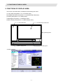
1. OUTLINE
1.1 System Outline
1. OUTLINE
1.1 System Outline
This manual is an instruction manual for NAVI MILL for 700/70 (hereafter NAVI MILL).
The part program for the vertical machining center (three axes of X, Y and Z) is created with the NAVI MILL.
(1) The following machining processes can be edited.
• Hole drilling (Drilling, pecking, step, boring, tapping, helical boring)
• Face cutting (Circle, square)
• Contour cutting (Circle, square, free)
• Pocket machining (Circle, square, L pattern, U pattern, track)
• EIA
(2) The tool file and the cutting condition file are provided and the cutting conditions are determined
automatically.
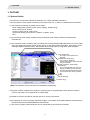
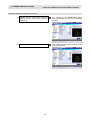
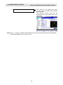
(3) The operation screen consists of the LIST VIEW area and the OPERATION VIEW area. In the LIST VIEW
area, the whole part program can be always viewed. In the OPERATION VIEW area, there are the guide
drawings related to the input items, and the data can be easily input by using these guide drawings.
[LIST VIEW area]
The object of the NAVI MILL is
selected.
[OPERATION VIEW area]
The screen is displayed
corresponding to the object selected
in the LIST VIEW.
[Cutting conditions automatically
determined]
Upon tool registration No. entry, the
cutting conditions for each process
are automatically determined based
on the tool file and cutting condition
file.
[Help]
[Guide drawing]
[Menu keys]
(Note) The operation screen size is fixed to 800(width) x 600(length).
(4) Program Checker enables the tool paths of a part program to be graphically traced. With this function,
errors in input data can be detected at an earlier stage.
(5) Guidance function provides an operator with error recovery information.
(6) Part program is a macro-program-based NC program. Commands can be added between processes from
the edit screen of the standard MELDAS 700/70 Series.
(7) The macro program mentioned above can be customized by the machine tool builder.
-1-
1. OUTLINE
1.2 Input Procedures
1.2 Input Procedures
The input procedure for the NAVI MILL is shown below.
The part
is operated on
the NAVI MILL’s screen.
Start
File edition
Tool file
Cutting condition file
Parameter setting
Parameter file
(The parameter setting is valid
even if the parameter is set after
editing the NC program)
NC program selection
Newly create
Read out
Supplements
Tool file
Cut condition file
(Tool registration No. 1 to 99)
(Work registration No.1 to 8)
99
Tool leng. offset
1 No.
Tool leng. offset
Tool leng.
offset
No.
Tool diam.
offset
No. No.
Tool diam.
offset
Spindle
rotation
No.
direction
Spindle rotation
direction
:
8
Material
1
Tool applicable
Material
: rotation rate
Tool applicable
:
rotation rate
:
Parameter setting
• M0 output • M6 output • M19 output •Next tool preparation, etc.
• Common parameters for hole drilling process (Z clearance, tap
selection)
• Common parameters for face cutting process (XYZ clearance, Z
approach G code)
• Common parameters for contour cutting / pocket machining
process
Process editing
Process editing:
Initial conditions
Process mode selection
Process data input
Hole drilling / Face cutting /
Contour cutting / Pocket
machining / EIA, etc.
Program check
Program Checker is used.
Program check
(Note) Set the tool
compensation amount and
workpiece coordinate system
offset to perform Program
Check. This function is realized
by using the 700/70 Series
graphic check function.
The NC program, tool file, cutting condition file and
parameter file transferred to the CNC can be edited on
Magicpro-NAVI MILL for 60S.
NC program operation
END
-2-
1. OUTLINE
1.3 Screen Configuration
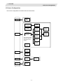
1.3 Screen Configuration
The screen configuration for the MILL NAVI is shown below.
Program
Process
Program
edit
screen
Process list
screen
Multiple
parts
screen
Initial
condition
setting screen
Hole
drilling
screen
Face
cutting
screen
Process
mode select
screen
Contour
cutting
screen
(For a new process,
select the process
form the process
mode.)
Pocket
screen
EIA
screen
Program
checker
Tool file
screen
File
Cutting
condition
file screen
Parameter
Parameter
screen
Version
Version
screen
Preference
screen
-3-
Machining
pattem
screen
Cutting
condition
screen
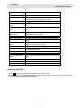
1. OUTLINE
1.3 Screen Configuration
Screen name
Title screen
Program edit screen
Process list screen
Multiple parts screen
Process mode select
screen
Initial conditions setting
screen
Hole drilling screen
Hole drilling machining
pattern screen
Cutting condition screen
Face cutting screen
Contour cutting screen
Contour cutting pattern
screen
Pocket screen
Pocket pattern screen
EIA screen
Tool file screen
Cutting condition file
screen
Parameter screen
Preference screen
Version screen
Program checker
Details
This screen is displayed when the power is turned ON.
The process program is read out and saved, etc.
Tool information and cutting conditions for each
process of a machining program are listed.
A NC program for the multiple parts machining is
generated.
The process mode (hole drilling, etc.) is selected.
The initial conditions for the process program are set.
The parameters for the hole drilling process are input.
The parameters related to the machining pattern of the
hole drilling process are input.
The cutting conditions by the process are input.
The parameters for the face cutting process are input.
The parameters for the contour cutting process are
input.
The parameters related to the machining pattern of the
contour cutting process are input.
The parameters of the pocket process are input.
The parameters related to the machining pattern of the
pocket process are input.
The EIA process is input.
The tool data by each tool is registered.
The cutting conditions (speed rate) by each process are
input.
The tool code and miscellaneous parameter are set.
The system is set up.
The version data of the NAVI MILL is displayed.
The tool paths of a NC program is graphically traced.
1.4 Starting NAVI MILL
Select
function, then [NAVI] menu to display NAVI MILL screen.
Program edit screen is displayed once when the power is turned ON. Then, whatever the screen previously
selected with NAVI MILL is displayed thereafter.
EDIT
-4-
1. OUTLINE
1.5 Setting up NAVI MILL
1.5 Setting up NAVI MILL
Part program output from NAVI MILL is a macro-program-based NC program. Thus, macro programs have to
be registered in the NC system in advance. Also, the destinations where NC programs or NAVI MILL's
reference files are saved, as well as the unit for data input, have to be specified prior to NAVI MILL
operations.
NAVI MILL setup items
Item
PATH
PROGRAM
Details
Standard value
Path to the folder in which NC program is saved.
PATH
Path to the folder in which tool file, cutting condition file
PARAMETER and parameter file are saved.
MACRO
Macro program mode
1: User macro mode
2: MTB macro mode
UNIT
Unit for data input
1: inch
2: mm
MEM:/
In 700 Series:
D:/NCFILE/NAVI
In 70 Series:
MEM:/
1 (User Macro)
2 (mm)
NAVI MILL setup procedures
(1)
Open PARAMETER screen.
(2)
Set "999 MAINTE" to 1.
[PREFERENCE] menu is displayed.
(3)
Press [PREFERENCE] menu.
PREFERENCE screen is displayed.
(4)
Select the macro type.
(1:Uer macro 2:MTB macro)
-5-
1. OUTLINE
1.5 Setting up NAVI MILL
(5)
Press [MACRO ENTRY] menu.
"OK?(Y/N)" message is displayed.
(6)
Press [Y] key.
Macro program is registered in NC system.
(7)
Enter the program path.
(8)
Enter the parameter path.
(9)
Select the unit.
(1:inch, 2:mm)
When the unit is changed, turn the power OFF
and ON again.
(Addendum)
• Always carry out a macro program registration when setting up NAVI MILL or switching "MACRO" types.
• Change "PROGRAM PATH" and "PARAMETER PATH" when necessary.
• When "UNIT" is changed, turn the power OFF and ON again.
• If the tool file, cutting condition file and parameter file do not exist in "PARAMETER PATH" folder when the
power is turned ON, those files are created by the system.
-6-
2. FUNCTIONS OF DISPLAY AREA
2. FUNCTIONS OF DISPLAY AREA
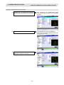
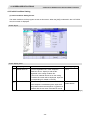
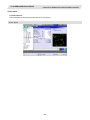
The screen of the NAVI MILL is divided into the following five areas.
(1) LIST VIEW area (Refer to "2.1 LIST VIEW Area")
(2) OPERATION VIEW area (Refer to "2.2 OPERATION VIEW Area")
(3) Setting area (Refer to "2.3 Setting Area")
(4) Message area (Refer to "2.4 Message Area")
(5) Menu display area (Refer to "2.5 Menu Display Area")
(1) LIST VIEW area
(2) OPERATION VIEW area
(4) Message area
(3) Setting area
(5) Menu display area
<Screen example>
-7-
2. FUNCTIONS OF DISPLAY AREA
2.1 LIST VIEW Area
2.1 LIST VIEW Area
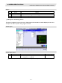
The object of the NAVI MILL is selected in this area.
(1) Area bar
(2) Object
(3) Cursor
(1) Area bar
When the LIST VIEW area is active, the area bar is highlighted.
(2) Objects
The list of objects that can be selected are displayed. The object is composed of the main object and the
sub object that the main object is detailed. The details of each object are as follows.
Main object
PROGRAM
PROCESS
FILE
Sub object
0 INIT
1 DR-LINE
:
TOOL
CUT CONDTN
PARAMETER
-
VERSION
-
Details
Newly creates, reads out, and deletes, etc. the NC program.
Displays the currently edited process list.
The settings of the selected process can be displayed and
changed.
Displays and changes the tool file.
Displays and changes the cutting conditions for each process
per workpiece material.
Displays the tool option and the miscellaneous parameter to
be used in each process. Those can be changed.
Displays the version data of the NAVI MILL.
(Note) If too many processes are registered and all the objects cannot be displayed, a scroll bar will be
displayed. In this case, change display of the list by pressing cursor key or page key down, or by
clicking on the scroll bar.
-8-
2. FUNCTIONS OF DISPLAY AREA
2.1 LIST VIEW Area
(3) Cursors
When the LIST VIEW area is active and the object is selected with the cursor, the display in the
OPERATION VIEW area and the menu display area will be changed.
<Cursor Movement>
The cursor is moved using the cursor keys or a pointing device.
Key type
[↑] Cursor key
[→] Cursor key
Operation of cursor
Moves the cursor one field up regardless of the main object or sub object.
Note that if the ↑ cursor is pressed when the cursor is at the top, the cursor
does not move.
Moves the cursor one field down regardless of the main object or sub object.
Note that if the ↓ cursor is pressed when the cursor is at the bottom, the cursor
does not move.
When the cursor is at the sub object, moves the cursor to the previous main
object.
When the cursor is at the sub object, moves the cursor to the next main object.
[Page Up] key
Moves the displayed data toward the top.
[Page Down]
key
Pointing device
Moves the displayed data toward the bottom.
[↓] Cursor key
[←] Cursor key
Cursor jumps to the spot where clicked with a pointing device. If an object not
selectable is clicked, cursor does not jump.
-9-
2. FUNCTIONS OF DISPLAY AREA
2.2 OPERATION VIEW Area
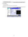
2.2 OPERATION VIEW Area
The various data are displayed in this area. Selecting the object in the LIST VIEW area changes the contents
displayed in the OPERATION VIEW area.
(1) Area bar
(2) Help
(3) Guide drawing
(4) Sub cursor
(1) Area bar
When the OPERATION VIEW area is active, the area bar is highlighted.
The name of the currently edited program is displayed.
(2) Help
Quick reference on the setting items is displayed.
(3) Guide drawing
When the process is edited, a guide drawing according to the currently edited machining mode is
displayed.
(4) Sub cursor
Key type
[↑] Cursor key
[↓] Cursor key
[Page Up] key
[Page Down]
key
Operation of cursor
Moves the cursor one field up.
Note that if the ↑ cursor is pressed when the cursor is at the top, the cursor
does not move.
Moves the cursor one field down.
Note that if the ↓ cursor is pressed when the cursor is at the bottom, the cursor
does not move.
Moves the displayed data toward the top.
Moves the displayed data toward the bottom.
- 10 -
2. FUNCTIONS OF DISPLAY AREA
2.3 Setting Area
2.3 Setting Area
The value to be set to data is input.
2.4 Message Area
An error message or operation message, etc. during operation is displayed.
2.5 Menu Display Area
The screen operation is selected, and the screen is changed.
The different menus are displayed in each screen. (Refer to the chapter 4.)
- 11 -
3. BASIC OPERATIONS
3.1 Changing Active View
3. BASIC OPERATIONS
3.1 Changing Active View
To operate NAVI MILL, activate either LIST VIEW area or OPERATION VIEW area. When the VIEW is active,
the area bar is highlighted and data can be input. Use menu keys [←] and [→] or a pointing device to change
one of the VIEWs to be activated.
3.2 Changing Screen
When the object is selected in the LIST VIEW area, the screen (contents in the OPERATION VIEW area)
changes. (Refer to the section 2.1 LIST VIEW Area.)
Note that the screen cannot be changed while the OPERATION VIEW area is active.
In such a case, press the [←] menu key or click "LIST VIEW" with a pointing device to turn the LIST VIEW
area active.
Operation example
(1) Open the program edit screen.
The OPERATION VIEW area is active.
(2) Press the [←] menu key.
The LIST VIEW area will turn active.
- 12 -
3. BASIC OPERATIONS
3.2 Changing Screen
(3) Select the object with the cursor key.
The OPERATION VIEW area will change
into the screen corresponding to the
selected object.
(4) Press the [MODIFY] menu key.
The OPERATION VIEW area will turn
active.
- 13 -
3. BASIC OPERATIONS
3.3 Setting Data
3.3 Setting Data
After moving the sub cursor, input the data into the setting area and then press the [INPUT] key, and the data
will be set. (The sub cursor is displayed only when the OPERATION VIEW area is active.)
Sub-cursor
Setting area
- 14 -
3. BASIC OPERATIONS
3.3 Setting Data
Operation method
An example for setting the data on the hole drilling screen is shown below.
(1) Screen selection
Select the object to be changed from the
LIST VIEW and press [MODIFY] menu
key.
(2) Setting item selection
Move the sub cursor with cursor keys.
(3) Data key input
Set data with the numeral keys or
alphabet keys, etc.
The OPERATION VIEW area will turn
active.
(Refer to the section 3.2 "Changing
screen".)
This is an example of the sub cursor
movement on the hole drilling screen.
The data is set in the data setting area.
18.000
[1] [2] [3] [.] [4] [5] [6]
(4) [Input] key input
Press the [input] key.
Data for the selected setting item is set.
The sub cursor moves to the next position.
(Note 1) The contents in the data setting area are only displayed when [INPUT] key is not pressed and will
be invalidated if the screen is changed at this time. Data for the currently selected setting item
will be set when [INPUT] key is pressed.
(Note 2) If illegal data is set, an error occurs when [Input] is pressed. Set the correct data again.
- 15 -
3. BASIC OPERATIONS
3.3 Setting Data
Operations in the data setting area
The key is input at the position where the cursor is displayed. If a cursor is not displayed, the key input is
invalid.
When a key is input, the data appears at the cursor position, and the cursor moves one character space to
the right.
[→] / [←] keys: Moves the cursor one character to the left or right.
(1) The cursor is at the position shown on
the right.
123777|456
(2) Press the [→] key.
The cursor moves one character space to
the right.
1237774|56
[DETETE] key: Deletes the character in front of the cursor.
The cursor moves in the data setting area.
(1) Move the cursor to the position where
the data is to be deleted.
1234|56
(2) Press the [DETETE] key.
The character in front of the cursor is
deleted.
123|56
- 16 -
3. BASIC OPERATIONS
3.4 Switching Windows
3.4 Switching Windows
When a shortcut button on the keyboard is pressed, its corresponding window is displayed.
Button
Application
Displays the tool guidance window.
LIST
?
Displays the message guidance window.
Displays the checker window.
3.5 Switching Selection Tags
Menu tag
When a tag button on the keyboard is pressed, the main window and checker window can be switched over.
Button
Application
Selects the tag on the left.
Selects the tag on the right.
(Note 1) Depending on the keyboard specifications, tag button may not be available.
- 17 -
3. BASIC OPERATIONS
3.6 Inputting Operations
3.6 Inputting Operations
In addition to the method of directly inputting numeric data for specific data settings, a method to input the
operation results using four rules operators and function symbols can be used.
Input method
Numeric values, function symbols, operators and parentheses ( ) are combined and set in the data
setting area.
The operation results appear when the [INPUT] key is pressed. Data for the currently selected setting item
will be set when [INPUT] key is pressed again.
The contents in the data setting area are erased.
Examples of operator settings,
and results
Setting
example
Operation
Function symbols, setting examples
and results
Operation
results
Function
Absolute
value
Addition
=100+50
150.000
Subtraction
=100−50
50.000
Square root
Multiplication =12.3∗4
49.200
Sine
Division
=100/3
33.333
Function
=1.2∗
(2.5+SQRT(4))
5.4
Function
symbol
Setting
example
ABS
=ABS (50−60)
10
=SQRT (3)
1.732
SIN
=SIN
0.5
Cosine
COS
=COS (15)
0.966
Tangent
TAN
=TAN
1
Arc tangent
Circle ratio
Inch
SQRT
Operation
results
ATAN
PAI
INCH
(30)
(45)
=ATAN (1.3)
52.431
=PAI*10
31.415
=INCH/10
2.54
Operation examples
(1) Set as shown below, and press the
[Input] key.
=12∗20
[Input]
(2) Press the [Input] key again.
The operation results appear in the data
setting area.
240 |
Data for the selected setting item is set.
The cursor moves to the next position.
Notes for using operators and functions
Division
Square root
Triangle function
Arc tangent
:
:
:
:
Zero division causes an error.
If the value in the parentheses is negative, an error occurs.
The unit of angle θ is degree (°).
−90 < operation results < 90.
Restrictions
• Always use "=" for the first character.
• Do not use the following characters as the second character or last character.
Invalid as second character: ∗, /, )
Invalid as last character: ∗, /, (, +, • Make sure that the left parentheses and right parentheses are balanced.
• The 360° limit does not apply on the angle. SIN (500) is interpreted as SIN (140).
- 18 -
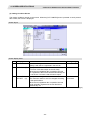
4. SCREEN SPECIFICATIONS
4.1 Starting NAVI MILL
4. SCREEN SPECIFICATIONS
4.1 Starting NAVI MILL
When NAVI MILL is started, the program edit screen will be displayed.
Screen layout
At the initial start up of NAVI MILL, the cursor is displayed at the position of [PROGRAM] in the LIST VIEW
area, and the program edit screen is displayed in the OPERATION VIEW area.
The LIST VIEW area is active.
The process program is not selected.
- 19 -
4. SCREEN SPECIFICATIONS
4.2 Screen Related to the Program
4.2 Screen Related to the Program
4.2.1 Program Edit Screen
The NC program is newly created and read out, etc. on this screen. When [PROGRAM] is selected in the
LIST VIEW area, this screen is displayed.
Screen layout
The process list of the currently selected program is displayed in the LIST VIEW area.
- 20 -
4. SCREEN SPECIFICATIONS
4.2 Screen Related to the Program
< Process displays >
Drilling
Display
character
DR-****
Pecking
PECK-****
Step
STEP-****
Boring
BORE-****
Tapping
(TAP-****)
Helical boring
HLX-BORE ?
Square
Circle
Square
Circle
Free
Square
Circle
L pattern
U pattern
Track
FACE-SQR ?
FACE-CIR ?
CNT-SQR ?
CNT-CIR ?
CNT-FREE ?
PKT-SQR ?
PKT-CIR ?
PKT-LPT ?
PKT-UPT ?
PKT-TRK ?
EIA (EIA)
Process name
Hole drilling
Face cutting
Contour
cutting
Pocket
EIA
Remarks
The symbol (abbrev.) which indicates the
machining pattern is applied to the "****" part.
● Random : RNDM
● Linear
: LINE
● Arc
: ARC
● Circle
: CIR
● Square : SQR
● Grid
: GRID
The symbol which indicates the machining
type (rough / finishing) is applied to the "?"
part.
● Rough : R
● Finishing : F
The symbol which indicates the machining
type (rough / finishing) is applied to the "?"
part.
● Rough : R
● Finishing : F
Screen display item
No.
Display item
1
PROGRAM LIST
Details
Displays the program number and comment of the
NC program that can be currently read out.
- 21 -
Setting range
-
4. SCREEN SPECIFICATIONS
4.2 Screen Related to the Program
Menus
No.
Menu
1
←
2
NEW
3
OPEN
Details
Turns the LIST VIEW area active.
Newly creates the NC program. (Note 1)
< Display in the setting area when pressing the menu >
O(
) COMMENT(
)
Reads out the existing NC program. (Note 1) (Note 2)
< Display in the setting area when pressing the menu >
O(
)
When this menu is pressed, the cursor appears at the program list's
name section. When the setting area is empty, select a program with
the cursor and press the [INPUT] key to read the program.
Cursor
4
COPY
5
COMMENT
6
RENAME
7
DELETE
8
LIST UPDATE
Copies the existing NC program to another program. (Note 1)
< Display in the setting area when pressing the menu >
O(
) → O(
)
Edits the comment in the NC program. (Note 1)
< Display in the setting area when pressing the menu >
O(
) COMMENT(
)
Renames the existing NC program. (Note 1)
< Display in the setting area when pressing the menu >
O(
) → O(
)
Deletes the NC program.
< Display in the setting area when pressing the menu >
O(
) to O(
)
Updates the list display.
(Note 1) 1 to 7999 or 10000 to 99999999 can be set for the O No, and up to 18 alphanumeric characters
can be set for the comment.
(Note 2) NC program mode includes user macro mode and MTB mode. (This is specified in the
preferences screen.) When user macro mode is active and an NC program created with MTB
mode is opened, the NC program is converted into user macro mode. When MTB mode is active
and an NC program created with user macro mode is opened, the NC program is converted into
MTB mode.
- 22 -
4. SCREEN SPECIFICATIONS
4.2 Screen Related to the Program
Operation example (Opening the existing NC program)
(1) Select the [PROGRAM] in the LIST
VIEW area.
The program edit screen will be displayed.
The list of the NC program that can be read
out will be displayed.
(2) Press the [OPEN] menu key, and input
the NC program No. to be read out.
The [OPEN] menu will be highlighted, and
the setting area will be displayed.
(3) Press the [INPUT] key.
The highlight of the [OPEN] menu will turn
OFF, and the setting area will disappear.
The process of the NC program read out
will be displayed in the LIST VIEW area.
The NC program No. read out will be
displayed on the area bar of the
OPERATION VIEW area.
- 23 -
4. SCREEN SPECIFICATIONS
4.3 Screens Related to the Process Edit Functions
4.3 Screens Related to the Process Edit Functions
4.3.1 Process List Screen
The tool information and cutting conditions for each process are displayed on this screen. When [PROCESS]
is selected in the LIST VIEW area, this screen is displayed.
When the NC program is not selected, this screen is not displayed.
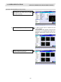
Screen layout
- 24 -
4. SCREEN SPECIFICATIONS
4.3 Screens Related to the Process Edit Functions
Screen display items
No.
Display item
1
PCS
2
3
4
T NAME
T
NT
5
H
6
D
7
8
S
F
Details
The process name is displayed.
(Note) This name is same as the name displayed
in the LIST VIEW area.
The name of tool to be used is displayed.
Specify the No. of tool to be used.
Specify the No. of tool to be used in the next
process. According to the specified tool No., the
tool is determined after the tool change.
(Note) When "1" is set in the parameter "103
NEXT TOOL PREP", this data is valid.
Specify the tool length offset No.
The maximum value for the H is changed
according to the specifications.
Specify tool diameter offset No.
The maximum value for the D is changed
according to the specifications.
Input the spindle rotation speed.
Input the feedrate.
When the hole cycle type is "TAP", input the pitch
(mm/rev).
Setting range
-
0 to 9999
0 to 9999
1 to number of tool
sets
1 to number of tool
sets
1 to 99999 rev/min
0.001 to
60000.000 mm/min
0.001 to
999.999 mm/rev
Menus
No.
Menu
1
←
2
NEXT T PRESET
3
MULTI PT
4
SAVE
Details
Turns the LIST VIEW area active.
Sets the next tool No. automatically. For the next tool No., the tool No.
of the next process is set.
Multiple Parts screen is displayed.
When using the Multiple Parts function, press “MULTI PT”.
Saves changes in the process list.
- 25 -
4. SCREEN SPECIFICATIONS
4.3 Screens Related to the Process Edit Functions
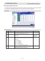
4.3.2 Multiple Parts Screen
Multiple Parts function enables you to generate a NC program that allows one designated machining process
to be completed at once for multiple workpieces. This NC program can be generated based on the NC
programs generated for a single part machining with the appropriate arrangement of the multiple workpieces.
When working on multiple workpieces, there are two options available to specify their positions:
• by identifying the values of the work-coordinate system per each workpiece.
• by determining each offset amount from one specific work coordinate.
As for machining pattern, there are two options available:
• to have one machining process completed for all workpieces on the table before moving on to the next
machining process (the number of times to execute tool-changes can be reduced by choosing this option).
• to have entire machining processes completed per each workpiece.
(Note 1) The NC program generated with the Multiple Parts function is differed from its original NC program.
(Note 2) The NC program generated with the Multiple Parts function cannot be edited with NAVI MILL. If
editing is attempted, the operation message “No init process, Create OK? (Y/N)” appears.
<Drawing>
<NAVI MILL base function>
200
90
70
90
160
35
35
50
70
50
50
9-M8 P=1.25 Depth8
Prepared hole Φ6.8 Depth12
Program for single part
90 130
35
8R1
0
30
35
50
50
4-Φ6.8 Penetration
6-Φ6.8 Hole Depth17
5
10
15
20
<Layout of workpieces>
Program for multiple parts
Program generater
for multiple parts
- 26 -
4. SCREEN SPECIFICATIONS
4.3 Screens Related to the Process Edit Functions
To view the “Multiple Parts Screen”, go to the “Process List Screen” and press [MULTI PT] menu.
Screen Layout
- 27 -
4. SCREEN SPECIFICATIONS
4.3 Screens Related to the Process Edit Functions
Screen Details
No.
1
Display item
PROGRAM O
Details
Setting range
Program No. and comments are input.
-
Avoid using the same program No. for the Multiple
Parts NC program and the currently editing program. If
a duplicated program No. is used for both programs, an
error message occurs.
2
NUM OF PARTS
Number of parts is input.
2 to 8
3
MACHINING
Machining pattern is selected.
1 to 2
1: A pattern that has one machining process
completed for all workpieces before moving on
to the next machining process
2: A pattern that has entire machining processes
completed per one workpiece before moving
on to the next workpiece
- 28 -
4. SCREEN SPECIFICATIONS
4.3 Screens Related to the Process Edit Functions
No.
4
Display item
COORDINATE
Details
The method to specify the position of multiple
workpieces is selected.
Setting range
1 to 2
1: A method that identifies the values of the
work-coordinate system per each workpiece
2: A method that determines each offset amount
from
one specific work coordinate
5
X
Y
The value of each workpiece position is input
depending on the offset amount from one specific work
coordinate.
This is valid when selecting "2" in the COORDINATE
screen.
WC
The value of the work-coordinate system per each
workpiece is input.
This is valid when selecting "1" in the COORDINATE
screen.
(Note) Program No. can be selected from 1 to 7999 or 10000 to 99999999.
Comment section allows up to 18 characters/numbers.
-99999.999 to
99999.999mm
54 to 59
P1 to P48
Menu
No.
Menu
Details
1
GEN PRGM
Generate a NC program for the Multiple Parts machining.
2
RETURN
Return to the Process List Screen.
- 29 -
4. SCREEN SPECIFICATIONS
4.3 Screens Related to the Process Edit Functions
4.3.3 Operating Process
When the cursor is moved to the sub-object of PROCESS in the LIST VIEW area, a menu for editing the
process is displayed, and the process can be operated.
Screen layout
Menus
No.
Menu
1
MODIFY
2
NEW
3
4
MOVE
DELETE
5
COPY
Details
The OPERATION VIEW area turns active, and the process parameters
can be changed.
Adds a new process.
The process will be inserted into the cursor position.
Changes the process position.
Deletes the process at the cursor position.
When performing the deletion, the process under the deleted process
will be moved up.
Copies the process at the cursor position.
The copied process will be inserted under the cursor position.
- 30 -
4. SCREEN SPECIFICATIONS
4.3 Screens Related to the Process Edit Functions
Operation example (Selecting the process)
(1) Validate the LIST VIEW area and select
the process with the cursor key.
The contents of the OPERATION VIEW
area will change to those of the selected
process.
(2) Press the [MODIFY] menu key.
The OPERATION VIEW area will turn
active.
- 31 -
4. SCREEN SPECIFICATIONS
4.3 Screens Related to the Process Edit Functions
Operation example (Deleting the process)
(1) Validate the LIST VIEW area, select the
process to be deleted with the cursor
key.
The contents of the OPERATION VIEW
area will change to those of the selected
process.
(2) Press the [DELETE] menu key.
The [DELETE] menu will be highlighted,
and a massage confirming the deletion will
appear.
(3) Press the [Y] key.
The highlight of the [DELETE] menu will
turn OFF, and the process at the cursor
position will be deleted.
The process under the deleted process will
be moved up one.
The contents in the OPERATION VIEW
area will change to those of the process at
the cursor position.
When not deleting the process, press the
[N] key
- 32 -
4. SCREEN SPECIFICATIONS
4.3 Screens Related to the Process Edit Functions
Operation example (Copying the process)
(1) Validate the LIST VIEW area, select the
process of the copy source with the
cursor key.
The contents of the OPERATION VIEW
area will change to those of the selected
process.
(2) Press the [COPY] menu key.
The copied process will be inserted under
the cursor position.
- 33 -
4. SCREEN SPECIFICATIONS
4.3 Screens Related to the Process Edit Functions
Operation example (Moving the process)
(1) Validate the LIST VIEW area, select the
process to be moved with the cursor key.
The contents of the OPERATION VIEW
area will change to those of the selected
process.
(2) Press the [MOVE] menu key.
The [MOVE] menu will be highlighted.
The mark "M" will be displayed beside the
process to be moved.
(3) Select the position of the movement
destination with the cursor key.
- 34 -
4. SCREEN SPECIFICATIONS
4.3 Screens Related to the Process Edit Functions
(4) Press the [INPUT] key.
The message to confirm a movement is
displayed.
If the [MOVE] menu key is pressed again
during the movement operation, the
movement operation will be canceled.
(5) Press the [Y] key.
When not moving the process, press the
[N] key.
(Note) For the [NEW] menu, refer to the next section.
- 35 -
The process of the movement source will
be moved to the cursor position.
The highlight of the [MOVE] menu will turn
OFF.
4. SCREEN SPECIFICATIONS
4.3 Screens Related to the Process Edit Functions
4.3.4 Process Mode Selection Screen
When a new process is added, the process mode is selected on this screen.
Screen layout
Screen display item
No.
1
Display item
Process mode
Details
Displays the process mode that can be selected.
Select the process mode by moving the sub-cursor
or inputting numerical values.
Menu
No.
1
←
Menu
Details
Cancels adding a new process.
The LIST VIEW area will turn active after cancel.
- 36 -
Setting range
1 to 5
4. SCREEN SPECIFICATIONS
4.3 Screens Related to the Process Edit Functions
Operation example(Adding a new process)
(1) Validate the LIST VIEW area, and select
the position where the process is added
with the cursor key.
(2) Press the [NEW] menu key.
A blank process will be inserted into the
cursor position.
The process mode selection screen will be
displayed in the OPERATION VIEW area,
and the OPERATION VIEW area will turn
active.
(3) Select the process mode with the cursor
or the numerical value input.
- 37 -
4. SCREEN SPECIFICATIONS
4.3 Screens Related to the Process Edit Functions
(4) Press the [INPUT] key.
The contents in the OPERATION VIEW
area will change into those of the selected
process mode.
The selected process mode will be
displayed at the cursor position in the LIST
VIEW area.
(Note) If the [←] menu key is pressed during adding the process, the screen will return to the state before
pressing the [NEW] menu key (state of the 1).
- 38 -
4. SCREEN SPECIFICATIONS
4.3 Screens Related to the Process Edit Functions
4.3.5 Initial Condition Setting
(1) Initial Condition Setting Screen
The initial conditions for the program are set on this screen. When the [INIT] is selected in the LIST VIEW
area, this screen is displayed.
Screen layout
Screen display items
No.
1
Display item
WORK REG No.
Details
Input the registration No. of the workpiece
material to be cut. Specify it with the No.
registered in the cutting condition file.
(The list of material names set on the cutting
condition file screen will be displayed. Input the
corresponding No. based on the list.)
Setting range
1 to 8
2
INITIAL POS Z
Input the initial position Z.
In the workpiece coordinate system, input the Z
axis position where the workpiece or jig does not
interfere with the tool even if the table is moved.
-99999.999 to
99999.999mm
(Continued to the next page)
- 39 -
4. SCREEN SPECIFICATIONS
4.3 Screens Related to the Process Edit Functions
(Continued from the previous page)
No.
Display item
Details
WORK
Specify the workpiece coordinate system to be
3
COORDINATE
used.
Setting range
54 to 59
P1 to P48
54 : G54
:
59 : G59
P1 : G54.1 P1
:
4
ATC PATTERN X
ATC PATTERN Y
5
ATC POSITION X
ATC POSITION Y
6
END TOOL No.
7
END PATTERN X
END PATTERN Y
8
END POSITION X
END POSITION Y
9
END M CODE
P48 : G54.1 P48
Select the table position at the tool change (ATC)
with the following No.’s.
1 : No specification (The table is not moved.)
2 : 1st zero point
3 : 2nd zero point
4 : Specified position (The table is moved to the
specified ATC position.)
In the machine coordinate system, input the table
position at the tool change.
This is valid when "4" is set in the "ACT
PATTERN".
At the program end, input the tool No. that you
want to call.
If 0 is input, the tool used at the machining end
will be stopped with that attached to the spindle.
If the tool No. is input, the tool will be changed at
the machining end and then stopped.
Select the table position at the program end with
the following No.'s.
1 : No specification (The table is not moved.)
2 : 1st zero point
3 : 2nd zero point
4 : Specified position
(The table is moved to the specified end
position.)
In the machine coordinate system, input the table
position at the program end.
This is valid when "4" is set in the "END
PATTERN".
At the program end, select the M command to be
output.
1 : M30
2 : M02
3 : M99
- 40 -
1 to 4
-99999.999 to
99999.999mm
0 to 9999
1 to 4
-99999.999 to
99999.999mm
1 to 3
4. SCREEN SPECIFICATIONS
4.3 Screens Related to the Process Edit Functions
Menus
No.
Menu
Details
1
←
Turns the LIST VIEW area active.
2
WORK SHAPE
Workpiece Size Setting screen is displayed.
3
SAVE
Saves the changes in the initial conditions.
(2) Workpiece Size Setting Screen
The size of workpiece is set on this screen. Parameters on this screen are used to display the size of the
workpiece and the tool paths during Program Checker.
Screen layout
Screen display items
No.
1
Display item
WORK SHAPE
Details
Setting range
Input the shape of workpiece.
1, 2
1 : SQUARE 2 : CIRCLE
(Note) Display items No.2 and later differ according to each shape of workpiece.
- 41 -
4. SCREEN SPECIFICATIONS
4.3 Screens Related to the Process Edit Functions
• Parameters for SQUARE
No.
2
Display item
+X
Details
Input +X position based on the work coordinate
zero point.
Input –X position based on the work coordinate
zero point.
Input +Y position based on the work coordinate
zero point.
Input –Y position based on the work coordinate
zero point.
Input +Z position based on the work coordinate
zero point.
Input –Z position based on the work coordinate
zero point.
Setting range
-99999.999 to
99999.999mm
-99999.999 to
99999.999mm
-99999.999 to
99999.999mm
-99999.999 to
99999.999mm
-99999.999 to
99999.999mm
-99999.999 to
99999.999mm
Display item
CENTER X
Details
Input the center of the circle. (X)
3
CENTER Y
Input the center of the circle. (Y)
4
RADIUS R
Input the radius of the circle.
5
+Z
6
-Z
Input –Y position based on the work coordinate
zero point.
Input +Z position based on the work coordinate
zero point.
Setting range
-99999.999 to
99999.999mm
-99999.999 to
99999.999mm
0.001 to
99999.999mm
-99999.999 to
99999.999mm
-99999.999 to
99999.999mm
3
-X
4
+Y
5
-Y
6
+Z
7
-Z
• Parameters for CIRCLE
No.
2
Menu
No.
1
Menu
RETURN
Details
Returns to the initial condition setting screen.
- 42 -
4. SCREEN SPECIFICATIONS
4.3 Screens Related to the Process Edit Functions
4.3.6 Hole Drilling
(1) Hole Drilling Screen
The parameters for the hole drilling process are input on this screen.
Screen layout
- 43 -
4. SCREEN SPECIFICATIONS
4.3 Screens Related to the Process Edit Functions
Screen display items
No.
Display item
1
TOOL REG No.
Details
Setting range
Input the tool registration No. to be used.
1 to 99
Specify it with the No. registered in the tool file.
1 to 5
2
HOLE CYCLE
Input the type of the hole machining cycle.
<1: DRILL> (G81, G82)
The machining is performed as far as the hole
bottom at a stretch, and the tool is lifted up after
the hole bottom dwell has been executed.
<2: PECK> (G83)
The machining is performed as far as the middle
of the hole, and the tool is returned to the higher
position than the hole top each time. The
machining is performed as far as the hole bottom
with such operation repeatedly executed.
<3: STEP> (G73)
The machining is performed as far as the middle
of the hole, and the tool is returned each time by
the G73 return amount. The machining is
performed as far as the hole bottom with such
operations repeatedly executed.
<4: BORE> (G85, G89)
The machining is performed as far as the hole
bottom at a stretch, and the tool is lifted up with
the cutting feedrate after the hole bottom dwell
has been executed.
<5: TAP> (G84,G74)
The tap machining is performed as far as the hole
bottom, and the tool is lifted up with the reversed
rotation after the hole bottom dwell has been
executed.
<6: HELIX>
The machining is performed with helical
interpolation as far as the hole bottom, and then
the tool is lifted up.
(Note) Display items No.3 and later differ according to each type of hole machining cycle.
- 44 -
4. SCREEN SPECIFICATIONS
4.3 Screens Related to the Process Edit Functions
• When HOLE CYCLE is set from the types between 1 to 5 (DRILL, PECK, STEP, BORE or TAP)
-99999.999 to
INITIAL Z (ZI)
Input the initial position.
3
99999.999mm
The tool is returned to the initial position after the
machining has been finished.
SURFACE Z (ZF) Input the workpiece top surface.
-99999.999 to
4
99999.999mm
DEPTH (H)
Input the hole depth from the workpiece top surface -99999.999 to
5
99999.999mm
with an addition input method.
When the hole depth is changed, tool nose depth
will be automatically updated.
If the calculated NOSE DEPTH is 0 or below, the
data range over will occur.
0.001 to
NOSE DEPTH (B) Input the tool nose depth from the workpiece top
6
99999.999mm
surface with an addition input method.
When the tool nose depth is changed, the hole
depth will be automatically updated.
0.001 to
SPOT DIAMETER Input the tool radius of the workpiece face.
7
(D)
When the tool radius of the workpiece face is input, Tool diameter
DEPTH and NOSE DEPTH will be automatically
updated.
0.000 to
CUT AMOUNT
When the hole cycle type C=2 (PECK) or C=3
8
(STEP) is selected, input the cutting amount for one 99999.999mm
time. If a value other than 0.000 is input when
selecting the hole cycle type C=5 (TAP), the
pecking tap process will be applied.
9
DWELL
When the hole cycle type C=1 (Drilling), C=3 (Step), 0.000 to
C=4 (Boring), C=5 (Tap) is selected, input the dwell. 99999.999sec
10 PATTERN
The machining pattern is displayed.
RANDOM
LINE
ARC
CIRCLE
SQUARE
GRID
Perform changing the machining pattern on the
machining pattern screen.
1 to
11 SP SPEED
The spindle rotation speed is displayed.
Perform changing the spindle rotation speed on the 99999rev/min
cutting condition screen.
0.001 to
12 FEED RATE
The feedrate is displayed.
60000.000
When the hole cycle type is "TAP", the pitch is
mm/min
displayed.
Perform changing the feedrate on the cutting
0.001 to
999.999 mm/rev
condition screen.
- 45 -
4. SCREEN SPECIFICATIONS
4.3 Screens Related to the Process Edit Functions
• When HOLE CYCLE is set to 6 (HELIX)
No.
3
Display item
PROCESS
Details
Input the machining type.
<1: ROUGH >
The rough machining is performed and the finishing
allowance remains.
<2: FIN>
The finishing machining is performed to the
machining surface.
Approach
Helical interpolation
Allowance
XY
Finishing
allowance XY
Depth
Side surface
finishing machining
Hole diameter
4
5
6
7
8
9
10
11
INITIAL Z
Setting range
1,2
Escape
Input the initial position.
After machining, the tool returns to the initial position.
Input the workpiece top surface position.
-99999.999mm to
99999.999mm
SURFACE Z
-99999.999mm to
99999.999mm
POS X
Input the hole position (X).
-99999.999mm to
99999.999mm
POS Y
Input the hole position (Y).
-99999.999mm to
99999.999mm
HOLE
Input the hole diameter.
0.001mm to
DIAMETER
99999.999mm
DEPTH
Input the hole depth from the workpiece top surface
0.001mm to
with an addition input method.
99999.999mm
ALLOWANCE
Input the allowance of the side surface.
0.001mm to
XY
This data is valid for the rough machining only.
99999.999mm
FIN ALLOW XY Input the finishing allowance of the side surface.
0.000mm to
The rough machining leaves the finishing allowance in 99999.999mm
respect to the side surface.
This data is valid for the rough machining only.
- 46 -
4. SCREEN SPECIFICATIONS
4.3 Screens Related to the Process Edit Functions
No.
12
Display item
CUT AMOUNT
Z
Details
Input the cutting amount in Z-direction.
The remainder, if left after "DEPTH + CLEARANCE Z
/ CUT AMOUNT" has been applied, will be the last
cutting amount.
Clearance Z
Setting range
0.001mm to
99999.999mm
Cutting amount Z
Start XY
Surface Z
Hole depth
Remainder
Cutting amount XY
13
CUT AMOUNT
XY
Finishing allowance XY
Input the cutting amount in XY-direction.
This data is valid for the rough machining only.
0.001mm to
99999.999mm
Cutting amount XY
Finishing allowance XY
Last machining
Allowance XY
First machining
Hole position X,Y
Remainder
Hole diameter
14
CUT TYPE
15
SP SPEED
16
FEED RATE F
1,2
Input the cutting type (up-cutting, down-cutting).
1: DOWN
2: UP
When the HOLE CYCLE is set to 6 (HELIX), the
cutting type is set to 1 (DOWN) as a default value.
1 to 99999 (r/min)
The spindle rotation speed is displayed.
The spindle rotation speed is changed on the setting
screen for cutting conditions.
The feedrate is displayed. The feedrate is changed on 0.001 to 60000.000 mm/min
0.01 to 999.99 mm/rev
the setting screen for cutting conditions.
Menus
No.
1
2
3
4
5
Menu
←
CUT CONDTN
PATTERN
CHECKER
SAVE
Details
Turns the LIST VIEW area active.
Displays the setting screen for the cutting conditions.
Displays the selection screen for the machining pattern.
This menu is not displayed when HOLE CYCLE is set to 6 (HELIX).
Displays the checker screen. Selects this to check the set data.
Saves the changes in the process.
If an illegal parameter exists when saving, an error message will appear. If
the input parameter is illegal, the cursor moves to the illegal parameter
position. If the input parameters for the pattern input screen or cutting
condition screen are illegal, the screen name and error message will be
displayed.
- 47 -
4. SCREEN SPECIFICATIONS
4.3 Screens Related to the Process Edit Functions
(2) Hole Drilling Machining Pattern Screen
The parameters for the hole drilling machining pattern are input on this screen. When the [PATTERN] menu is
pressed on the hole drilling screen, this screen is displayed. This screen is not available when HOLE CYCLE
is set to 6 (HELIX).
Screen layout
Screen display items
No.
1
Display item
PATTERN
Details
Input the type of the hole machining pattern.
<1: RANDOM>
The machining points are randomly arranged.
<2: LINE>
The machining points are equally spaced on a line.
<3: ARC>
The machining points are equally spaced on an
arc.
<4: CIRCLE>
The machining points are equally spaced on a
circle.
<5: SQUARE>
The machining points are squarely arranged.
<6: GRID>
The machining points are arranged in grid.
(Note) Display items No.2 and later differ according to each pattern.
- 48 -
Setting range
1 to 6
4. SCREEN SPECIFICATIONS
4.3 Screens Related to the Process Edit Functions
• Parameters for RANDOM
No.
2
3
4
Displayed item
RETURN POINT
No.
POS X
POS Y
Details
Specify the return point when the hole drilling is
completed.
1: Initial point level return (G98)
2: R point level return (G99)
Input the hole No.
Input the hole position.
Setting range
1,2
1 to 50
-99999.999mm to
99999.999mm
• Parameters for LINE
No.
2
Display item
ANGLE
(A)
3
PITCH
4
5
NUM OF HOLES
BASE POS X
Details
Input the angle formed with the machining direction
and the positive direction of the X-axis.
Input the space from the machining point to the next
machining point.
Input the number of holes.
Input the 1st hole position (X).
6
BASE POS Y
Input the 1st hole position (Y).
7
RETURN POINT
Specify the return point that is applied after the hole
machining.
1: Initial point level return (G98)
2: R point level return (G99)
(K)
- 49 -
Setting range
-359.999 to
360.000°
0.000 to
99999.999mm
2 to 999
-99999.999 to
99999.999mm
-99999.999 to
99999.999mm
1, 2
4. SCREEN SPECIFICATIONS
4.3 Screens Related to the Process Edit Functions
• Parameters for ARC
No.
2
Display item
RADIUS
(R)
Details
3
4
START ANGLE
(A)
PITCH
(K)
5
6
NUM OF HOLES
BASE POS X
Input the angle formed with the first machining point
and the X-axis direction.
Input the angle from the previous machining point to
the next machining point.
Input the number of holes.
Input the arc center position (X).
7
BASE POS Y
Input the arc center position (Y).
8
RETURN POINT
Specify the return point that is applied after the hole
machining.
1: Initial point level return (G98)
2: R point level return (G99)
Input the arc radius.
Setting range
0.001 to
99999.999mm
-359.999 to
360.000°
-359.999 to
360.000°
2 to 999
-99999.999 to
99999.999mm
-99999.999 to
99999.999mm
1, 2
• Parameters for CIRCLE
No.
2
Display item
DIAMETER (D)
Details
Input the circular diameter.
3
4
5
START ANGLE
(A)
NUM OF HOLES
BASE POS X
Input the angle formed with the first machining point
and the positive direction of the X-axis.
Input the number of holes.
Input the circular center position (X).
6
BASE POS Y
Input the circular center position (Y).
7
RETURN POINT
Specify the return point that is applied after the hole
machining.
1: Initial point level return (G98)
2: R point level return (G99)
- 50 -
Setting range
0.001 to
99999.999mm
-359.999 to
360.000°
1 to 999
-99999.999 to
99999.999mm
-99999.999 to
99999.999mm
1, 2
4. SCREEN SPECIFICATIONS
4.3 Screens Related to the Process Edit Functions
• Parameters for SQUARE
No.
2
6
Y NUM OF
HOLES
BASE POS X
Details
Input the width of the machining point in the X-axis
direction.
Input the number of machining points in the X-axis
direction.
Input the width of the machining point in the Y-axis
direction.
Input the number of machining points in the
Y-direction.
Input the position (X) of the machining start point.
7
BASE POS Y
Input the position (Y) of the machining start point.
8
RETURN POINT
9
ANGLE
(A)
10
ANGLE
(B)
11
OMIT 1 to 4
Specify the return point that is applied after the hole
machining.
1: Initial point level return (G98)
2: R point level return (G99)
Input the workpiece’s inclination angle between the
machining start direction and the X axis.
Input the interior angle.
Default value is 90°.
Specify the hole No. to be omitted (deleted).
Maximum hole No. that can be specified is 127.
3
4
5
Display item
X WIDTH
(I)
X NUM OF
HOLES
Y WIDTH
(J)
- 51 -
Setting range
-99999.999 to
99999.999mm
2 to 999
-99999.999 to
99999.999mm
2 to 999
-99999.999 to
99999.999mm
-99999.999 to
99999.999mm
1, 2
-359.999° to
360.000°
0.001° to
179.999°
1 to number of
holes
4. SCREEN SPECIFICATIONS
4.3 Screens Related to the Process Edit Functions
• Parameters for GRID
No.
2
6
Y NUM OF
HOLES
BASE POS X
Details
Input the width of the machining point in the X-axis
direction.
Input the number of machining points in the X-axis
direction.
Input the width of the machining point in the Y-axis
direction.
Input the number of machining points in the
Y-direction.
Input the position (X) of the machining start point.
7
BASE POS Y
Input the position (Y) of the machining start point.
8
RETURN POINT
9
ANGLE
(A)
10
ANGLE
(B)
11
OMIT 1 to 4
Specify the return point that is applied after the hole
machining.
1: Initial point level return (G98)
2: R point level return (G99)
Input the workpiece’s inclination angle between the
machining start direction and the X axis.
Input the interior angle.
Default value is 90°.
Specify the hole No. to be omitted (deleted).
Maximum hole No. that can be specified is 127.
3
4
5
Display item
X WIDTH
(I)
X NUM OF
HOLES
Y WIDTH
(J)
Setting range
-99999.999 to
99999.999mm
2 to 999
-99999.999 to
99999.999mm
2 to 999
-99999.999 to
99999.999mm
-99999.999 to
99999.999mm
1, 2
-359.999° to
360.000°
0.001° to
179.999°
1 to number of
holes
Menus
No.
1
2
Menu
RETURN
LINE INSERT
3
LINE DELETE
4
COPY
5
+INPUT
6
SORT X
7
SORT Y
Details
Returns to the hole drilling screen.
Inserts the hole position in front of the cursor position.
This is available for the RANDOM pattern only.
Deletes the hole position at the cursor position.
This is available for the RANDOM pattern only.
Copies the previous line data above cursor to the setting area.
This is available for the RANDOM pattern only.
Adds the previous line data above cursor to the setting data, and enters
the value to the setting area. This is available for the RANDOM pattern
only.
Sorts POS X and Y in ascending order based on POS X.
This is available for the RANDOM pattern only.
Sorts POS X and Y in ascending order based on POS Y.
This is available for the RANDOM pattern only.
- 52 -
4. SCREEN SPECIFICATIONS
4.3 Screens Related to the Process Edit Functions
(3) Cutting Condition Screen
The cutting conditions are set on this screen. When the [CUT CONDTN] menu is pressed on each process
edit screen, this screen is displayed.
Screen layout
Screen display items
No.
Display item
1
TOOL REG No.
2
TOOL T No. (T)
3
TOOL LENG
OFFSET (H)
Details
Setting range
Input the tool registration No. to be used.
1 to 99
Specify it with the No. registered in the tool file.
0 to 9999
Specify the tool No. to be used.
(T function code data output as the NC data)
When the tool registration No. is specified, the tool
No. registered in the tool file will be automatically set.
If 0 is set, the T function code will not be output.
1 to the number
Specify the tool length offset No.
of tool sets
The maximum value for the H is changed according
to the specifications.
When the tool registration No. is specified, the tool
length offset No. registered in the tool file will be
automatically set.
(Continued to the next page)
- 53 -
4. SCREEN SPECIFICATIONS
4.3 Screens Related to the Process Edit Functions
No.
Display item
4
TOOL DIAM
OFFSET
(D)
5
TOOL
DIAMETER
6
SP SPEED
7
FEED RATE
(Z)
(XY)
8
SP DIRECTION
(S)
(Continued from the previous page)
Details
Setting range
1 to the number
Specify tool diameter offset No.
of tool sets
The maximum value for the D is changed according
to the specifications.
When the tool registration No. is specified, the tool
diameter offset No. registered in the tool file will be
automatically set.
That can be also rewritten manually.
0.001 to
Input the tool diameter.
99999.999 mm
When the tool registration No. is specified, the tool
diameter registered in the tool file will be
automatically set.
1 to 99999
Input the spindle rotation speed.
The spindle rotation speed is automatically set based rev/min
on the standard rotation speed registered in the tool
file and the rate registered in the cutting condition file.
Spindle rotation speed
= Standard rotation speed × rate
0.001 to
Input the feedrate.
60000.000
Specify the pitch with mm/rev when tapping is
mm/min
selected in the hole drilling machining mode.
0.001 to
Specify the feedrate with mm/min in the other
999.999
machining mode.
mm/rev
The feedrate is automatically set based on the
standard feedrate registered in the tool file and the
rate registered in the cutting condition file.
Feedrate = Standard feedrate × rate
(Note) The setting items are changed according to
the process type.
<Hole drilling process, face cutting process>
FEED RATE
F
<Contour cutting process, pocket process>
FEED RATE
Z
FEED RATE
XY
1, 2
Input the spindle rotation direction.
When the tool registration No. is specified, the tool
rotation direction registered in the tool file will be
automatically set.
1: CW
2: CCW
Menu
No.
Menu
1
RETURN
Details
Returns the screen to the input screen for the hole process parameter.
- 54 -
4. SCREEN SPECIFICATIONS
4.3 Screens Related to the Process Edit Functions
4.3.7 Face Cutting
(1) Face Cutting Screen
The parameters for the face cutting process are set on this screen.
Screen layout
Screen display items
No.
1
Display item
TOOL REG No.
2
FACE CYCLE
3
PROCESS
Details
Setting range
Input the tool registration No. to be used. Specify it 1 to 99
with the No. registered in the tool file.
1, 2
Input the type of the face cutting cycle.
<1: SQUARE>
The face cutting machining in the square area is
performed.
<2: CIRCLE>
The face cutting machining in circular area is
performed.
1, 2
Input the type of the machining.
<1: ROUGH>
The rough machining is performed with cuttings of
the number of rough machinings, remaining the
finishing allowance.
<2: FIN>
The finishing machining is performed to the
finishing surface (Height of machining top surface
- allowance) at a stretch.
(Continued to the next page)
- 55 -
4. SCREEN SPECIFICATIONS
4.3 Screens Related to the Process Edit Functions
No.
4
Display item
BASE POS X
5
BASE POS Y
6
SURFACE Z (ZF)
7
ALLOWANCE (H)
8
FINISH ALLOW
(Q)
9
NUM OF CUTS
(T)
10
START POINT
11
CUT DIRECTION
12
PATH
13
SP SPEED
14
FEED RATE
(Continued from the previous page)
Setting range
-99999.999 to
99999.999mm
Input the position (Y) of the base point.
-99999.999 to
99999.999mm
Input the workpiece top surface position.
-99999.999 to
99999.999mm
Input the size of the allowance from the height of
0.001 to
the machining top surface.
99999.999mm
0.000 to
Input the size of the finishing allowance form the
99999.999mm
finishing surface.
The rough machining is performed to the machining
surface, remaining the finishing allowance.
(Note) This data is valid only when the rough
machining is specified.
1 to 99999
Input how many times the allowance is cut in the
Z-axis direction when performing the rough cutting. times
The cutting amount for one time is as follows.
Allowance – finishing allowance / Number of rough
machinings
(Note) This can be input only when the rough
machining is specified.
Input form which corner ((1) to (4)) in the four
1 to 4
screen guide drawings the machining is started.
1, 2
Input the direction (X-direction or Y-direction) in
which the machining is performed.
1: X
2: Y
Input the machining path (reciprocation machining, 1 to 3
single-direction machining, shape machining)
1: RECIP
2: SINGLE
3: SHAPE
1 to
The spindle rotation speed is displayed.
Perform changing the spindle rotation speed on the 99999rev/min
cutting condition screen.
0.001 to
The feedrate is displayed.
60000.000
Perform changing the feedrate on the cutting
mm/min
condition screen.
Details
Input the position (X) of the base point.
- 56 -
4. SCREEN SPECIFICATIONS
4.3 Screens Related to the Process Edit Functions
(Note) Display items No.15 and later differ according to each type of the face cutting cycle.
• Parameter used when the face cutting cycle is SQUARE
No.
15
16
17
18
19
Display item
WIDTH X
(I)
Details
Input the machining width of the machining surface
in the X-direction (horizontal direction).
This is valid when the face cutting cycle is
SQUARE.
WIDTH Y
(J) Input the machining width of the machining surface
in the Y-direction (vertical direction).
This is valid when the face cutting cycle is
SQUARE.
ANGLE
(A) Input the inclination angle of the machining surface.
This is valid when the face cutting cycle is
SQUARE.
CUT WIDTH X
Input the width of machining part in the X-direction
(WX) during the square machining.
This is valid when the face cutting cycle is
SQUARE.
CUT WIDTH Y
Input the width of machining part in the Y-direction
(WY) during the square machining.
This is valid when the face cutting cycle is
SQUARE.
- 57 -
Setting range
0.001 to
99999.999mm
0.001 to
99999.999mm
-359.999 to
360.000°
0.000 to
99999.999mm
0.000 to
99999.999mm
4. SCREEN SPECIFICATIONS
4.3 Screens Related to the Process Edit Functions
• Parameter used when the face cutting cycle is CIRCLE
No.
15
16
Display item
WORK RADIUS
(R)
CUT WIDTH (W)
Details
Input the radius of the workpiece surface.
This is valid when the face cutting cycle is CIRCLE.
Input the width of machining part during the circular
machining.
This is valid when the face cutting cycle is
SQUARE.
Setting range
0.001mm to
99999.999mm
0.000 to
99999.999mm
Menus
No.
Menu
1
←
2
CUT CONDTN
3
SAVE
Details
Turns the LIST VIEW area active.
Displays the setting screen for the cutting conditions.
Saves the changes in the process.
If an illegal parameter exists when saving, an error message will appear.
If the input parameter is illegal, the cursor moves to the illegal parameter
position. If the input parameters for the cutting condition screen are
illegal, the screen name and error message will be displayed.
(2) Cutting Condition Screen
The cutting conditions are set on this screen. When the [CUT CONDTN] menu is pressed on each process
edit screen, this screen is displayed. Refer to "(3) Cutting Condition Screen" in the section "4.3.6 Hole Drilling"
for details.
- 58 -
4. SCREEN SPECIFICATIONS
4.3 Screens Related to the Process Edit Functions
4.3.8 Contour Cutting
(1) Contour Cutting Screen
The parameters for the contour cutting process are set on this screen.
Screen layout
- 59 -
4. SCREEN SPECIFICATIONS
4.3 Screens Related to the Process Edit Functions
Screen display items
No.
1
2
Display item
TOOL REG
No.
PROCESS
Details
Input the tool registration No. to be used. Specify it with the
No. registered in the tool file.
Input the machining type.
<1: ROUGH>
Z-direction : The machining is performed with cuttings of
the number of cuttings, remaining the
finishing allowance Z.
XY-direction: The machining is performed with shifting,
remaining the finishing allowance XY.
<2: FIN>
First, the finishing machining of the bottom surface is
performed and then that of the side surface.
Finishing
Finishing machining
allowance XY
of the side surface
Finishing
allowance Z
Setting
range
1 to 99
1, 2
Finishing machining
of the bottom surface
[Finishing machining of the bottom surface]
Z-direction : The machining of the finishing allowance Z is
performed at a stretch.
XY-direction: The machining is performed with the shift of
the allowance, remaining the finishing
allowance XY.
When the finishing allowance Z is 0, the finishing
machining of the bottom surface is not performed.
[Finishing machining of the side surface]
Z-direction : The machining is performed with cuttings of
the number of cuttings.
XY-direction: The machining of the finishing allowance XY
is performed at a stretch.
When the finishing allowance XY is 0, the finishing
machining of the side surface is not performed.
3
SURFACE Z
(ZF)
Input the workpiece top surface position.
-99999.999 to
99999.999mm
(Continue to the next page)
- 60 -
4. SCREEN SPECIFICATIONS
4.3 Screens Related to the Process Edit Functions
(Continued from the previous page)
No. Display item
4
5
6
7
8
9
10
11
12
Details
ALLOWANC
EZ
(H)
ALLOWANC
E XY
(E)
Input the machining depth from the workpiece top surface
with the addition input method.
Input the allowance of the side surface.
(Note) This data is valid when the pattern type is CIRCLE,
SQUARE or FREE and RIGHT/LEFT is specified for
the tool path.
FIN ALLOW
Input the finishing allowance of the bottom surface.
Z
(FH) The rough machining is performed to the bottom surface,
remaining the finishing allowance.
FIN ALLOW
Input the finishing allowance of the side surface.
XY
(FE)
The rough machining is performed to the side surface,
remaining the finishing allowance.
(Note) This data is valid when the pattern type is CIRCLE,
SQUARE or FREE and RIGHT/LEFT is specified for
the tool path.
NUM OF
Input how many times the workpiece is cut in the Z-axis
CUTS Z (ZT) direction when performing the machining.
The cutting amount for one time is as follows.
Rough machining:
(Allowance – Finishing allowance) / Number of cuttings
Finishing machining of side surface:
Allowance/Number of cuttings
CUT TYPE
Input the cutting type (up-cutting, down-cutting).
1: DOWN
2: UP
(Note) This data is valid only when the pattern type is
CIRCLE or SQUARE.
PATTERN
The machining pattern is displayed.
CIRCLE SQUARE FREE
SP SPEED
The spindle rotation speed is displayed.
The spindle rotation speed is changed on the setting
screen for cutting conditions.
FEED RATE The feedrate in the XY-direction is displayed.
(XY) The feedrate is changed on the setting screen for cutting
conditions.
- 61 -
Setting
range
0.001 to
99999.999mm
0.001 to
99999.999mm
0.000 to
99999.999mm
0.000 to
99999.999mm
1 to 99999
times
1, 2
1 to 99999
rev/min
0.001 to
60000.000
mm/min
4. SCREEN SPECIFICATIONS
4.3 Screens Related to the Process Edit Functions
(Note) Depending on the machining pattern, the actual cutting amount of the side surfaces is differed as
shown below.
CIRCLE/ SQUARE
FREE (right-side/left-side)
FREE (center)
ALLOWANCE XY
ALLOWANCE XY
Tool diameter
CLEARANCE XY
Tool diameter
Menus
No.
1
2
3
4
Menu
←
CUT CONDTN
PATTERN
SAVE
Details
Turns the LIST VIEW area active.
Displays the setting screen for the cutting conditions.
Displays the selection screen for the machining pattern.
Saves the changes in the process.
If an illegal parameter exists when saving, an error message will
appear.
If the input parameter is illegal, the cursor moves to the illegal
parameter position. If the input parameters for the pattern input screen
or cutting condition screen are illegal, the screen name and error
message will be displayed.
- 62 -
4. SCREEN SPECIFICATIONS
4.3 Screens Related to the Process Edit Functions
(2) Contour Cutting Pattern Screen
The parameters for the contour cutting pattern are set on this screen. When the [PATTERN] menu is pressed
on the contour cutting screen, this screen is displayed.
Screen layout
Screen display items
No.
1
Display item
PATTERN
Details
Input the type of the contour cutting pattern.
<1: SQUARE >
The machining pattern of square shape
<2: CIRCLE >
The machining pattern of circular shape
<3: FREE>
The machining pattern of arbitrary shape that
consists of the straight line and arc
(Note) Display items No.2 and later differ according to each pattern.
- 63 -
Setting range
1 to 3
4. SCREEN SPECIFICATIONS
4.3 Screens Related to the Process Edit Functions
• Parameters for SQUARE
No.
2
Display item
MACHINING
SIDE
3
BASE POS X (X)
4
BASE POS Y (Y)
5
WIDTH
(I)
6
WIDTH
(J)
7
CORNER SIZE
(R)
Details
Input the machining position.
<1: INSIDE>
The machining is performed to the inside of the
shape.
<2: OUTSIDE>
The machining is performed to the outside of the
shape.
Input the base position X of the square.
-99999.999 to
99999.999mm
Input the base position Y of the square.
-99999.999 to
99999.999mm
Input the width of the square in the X-direction.
0.001 to
99999.999mm
Input the width of the square in the Y-direction.
0.001 to
99999.999mm
Input the corner size.
-99999.999 to
Positive value : Corner R, Negative value: Corner C 99999.999mm
R
8
ANGLE
(A)
9
START POINT
Setting range
1, 2
C
Input the workpiece’s inclination angle between the
square and X-axis.
Input the machining start position (1 to 4).
(Note) This data is valid when the machining
position is "OUTSIDE".
- 64 -
-359.999 to
360.000°
1 to 4
4. SCREEN SPECIFICATIONS
4.3 Screens Related to the Process Edit Functions
• Parameters for CIRCLE
No.
2
Display item
MACHINING
SIDE
3
BASE POS X (X)
Details
Input the machining position.
<1: INSIDE>
The machining is performed to the inside of the
shape.
<2: OUTSIDE>
The machining is performed to the outside of the
shape.
Input the center position X of the circle.
4
BASE POS Y (Y)
Input the center position Y of the circle.
5
RADIUS
Input the radius of the circle.
6
START POINT
(R)
Input the machining start position (1 to 4).
(Note) This data is valid when the machining
position is "OUTSIDE".
Setting range
1, 2
-99999.999 to
99999.999mm
-99999.999 to
99999.999mm
0.001 to
99999.999mm
1 to 4
• Parameters for FREE
No.
2
Display item
TOOL PATH
Details
Input the tool path.
<1: CENTER>
The machining is performed along the tool path
without the diameter offset.
<2: RIGHT>
The machining is performed along the tool path
with the offset to the right side (G42).
<3: LEFT>
The machining is performed to the tool path with
the offset in the right side (G41).
- 65 -
Setting range
1 to 3
4. SCREEN SPECIFICATIONS
4.3 Screens Related to the Process Edit Functions
No.
Display item
Shape
3
1 M
2
D
Details
Input the shape.
<1> The linear (G01) machining is performed.
<2> The CW arc (G02) machining is performed.
<3> The CCW arc (G03) machining is performed.
(Note) Omission is not possible.
Setting range
1 to 35
1 to 3
Input right turn or left turn in respect to the vector at 1,2
the end of the previous shape.
1: Left turn 2: Right turn
(Note 1) When nothing is input, it is regarded as
"contacting".
(Note 2) Omittable. However, when the end point
of the previous line, X and Z, is uncertain,
always input.
Left turn
Tangent
Right turn
3
X
Y
Input the position of the machining end point.
(Note 1) Always input if the line is the last one. If it
is not the last one, omission is possible.
(Note 2) Always input if the corner shape
dimensions are input in the previous line.
-99999.999mm to
99999.999mm
4
R/A
• When the shape is arc, the radius of arc is
Radius:
-999999.999mm
to -0.001mm,
0.001mm to
999999.999mm
Angle:
-359.999 to
360.000
entered.
Positive value: Arc command (less than 180˚)
Negative value: Arc command (more than 180˚)
• When the shape is line, angle is entered.
(Note 1) When the shape is arc, always input.
(Note 2) When the shape is line, and the position
X, Y or vector I, J are input, the data is
invalid.
- 66 -
4. SCREEN SPECIFICATIONS
4.3 Screens Related to the Process Edit Functions
No.
Shape
Display item
5
I
J
Details
Setting range
1 to 35
• When the shape is line, the gradient (vector) is
entered.
-99999.999mm to
99999.999mm
Y
End point of line "n"
30
End point of line
"n"-1
10
Programmed
zero point
60
20
X
• When the shape is arc, the position of the arc
center is entered.
Y
Line "n"
18
Programmed
zero point
Center
25
X
(Note 1) When the shape is arc, and only I or J is
entered, the other is regarded as 0.
(Note 2) When the shape is line, and the position
X, Y or angle is input, this data will be
invalid.
6
C
Input corner size.
Positive value: Corner R, Negative value: Corner C
R
-99999.999mm to
99999.999mm
C
(Note 1) When corner dimensions are specified,
the end points (X,Y) are entered for the
following line in principle.
(Note) The first point is a machining start point, so only the position X and Y can be input.
- 67 -
4. SCREEN SPECIFICATIONS
4.3 Screens Related to the Process Edit Functions
Menus
• For CIRCLE or SQUARE
No.
1
Menu
RETURN
Details
Returns the screen to the contour cutting screen.
• For FREE
No.
1
Menu
LINE INSERT
2
LINE DELETE
3
COPY
4
+INPUT
5
6
CLEAR
RETURN
Details
Inserts the shape data before the cursor position.
(Note) This menu is not available when the cursor is at No.1 (machining
start point).
Deletes the shape data at the cursor position.
(Note) This menu is not available when the cursor is at No.1 (machining
start point).
Copies the same data as that of previous line for the data at the cursor
position.
Input data at the cursor position with the data in the previous line added.
(Note) This is valid only when inputting the position X and Y.
Clears the data at the cursor position.
Returns the screen to the contour cutting screen.
(3) Cutting Condition Screen
The cutting conditions are set on this screen. When the [CUT CONDTN] menu is pressed on each process
edit screen, this screen is displayed. Refer to "(3) Cutting Condition Screen" in the section "4.3.6 Hole Drilling"
for details.
- 68 -
4. SCREEN SPECIFICATIONS
4.3 Screens Related to the Process Edit Functions
4.3.9 Pocket
(1) Pocket Screen
The parameters for the pocket process are set on this screen.
Screen layout
- 69 -
4. SCREEN SPECIFICATIONS
4.3 Screens Related to the Process Edit Functions
Screen display items
No.
Display item
Details
1
TOOL REG No.
2
PROCESS
Input the tool registration No. to be used. Specify it with
the No. registered in the tool file.
Input the machining type.
<1: ROUGH>
Z-direction : The machining is performed with cuttings
of the number of cuttings, remaining the
finishing allowance Z.
XY-direction: The machining is performed with shifting,
remaining the finishing allowance XY.
<2: FIN>
First, the finishing machining of the bottom surface is
performed and then that of the side surface.
Setting
range
1 to 99
1, 2
Finishing allowance XY
Finishing
machining of the
side surface
Finishing machining of
the bottom surface
Finishing
allowance Z
[Finishing machining of the bottom surface]
Z-direction : The machining of the finishing allowance
Z is performed at a stretch.
XY-direction: The machining is performed with the shift
of the allowance, remaining the finishing
allowance XY.
When the finishing allowance Z is 0, the finishing
machining of the bottom surface is not performed.
3
4
5
SURFACE Z
(ZF)
ALLOWANCE Z
(H)
FIN ALLOW Z
(FH)
[Finishing machining of the side surface]
Z-direction : The machining is performed with cuttings
of the number of cuttings.
XY-direction: The machining of the finishing allowance
XY is performed at a stretch.
When the finishing allowance XY is 0, the finishing
machining of the side surface is not performed.
Input the workpiece top surface position.
Input the machining depth from the workpiece top
surface with the addition input method.
Input the finishing allowance of the bottom surface.
The rough machining is performed to the bottom
surface, remaining the finishing allowance.
-99999.999 to
99999.999mm
0.001 to
99999.999mm
0.000 to
99999.999mm
(Continued to the next page)
- 70 -
4. SCREEN SPECIFICATIONS
4.3 Screens Related to the Process Edit Functions
(Continued from the previous page)
No.
Display item
6
FIN ALLOW XY
(FE)
7
NUM OF CUTS
Z
(ZT)
8
CUT TYPE
9
PATTERN
10
SP SPEED
11
FEED RATE
(XY)
Details
Setting
range
Input the finishing allowance of the side surface.
The rough machining is performed to the side surface,
remaining the finishing allowance.
Input how many times the workpiece is cut in the Z-axis
direction when performing the machining.
The cutting amount for one time is as follows.
Rough machining:
(Allowance – Finishing allowance) / Number of
cuttings
Finishing machining of side surface:
Allowance/Number of cuttings
Input the cutting type (down-cutting, up-cutting).
1: DOWN
2: UP
The machining pattern is displayed.
SQUARE CIRCLE
L PATTERN U PATTERN TRACK
The machining pattern is changed on the machining
pattern screen.
The spindle rotation speed is displayed.
The spindle rotation speed is changed on the setting
screen for cutting conditions.
The feedrate in the XY-direction is displayed.
The feedrate is changed on the setting screen for cutting
conditions.
0.000 to
99999.999mm
1 to 99999
times
1, 2
-
1 to 99999
rev/min
0.001 to
60000.000
mm/min
Menus
No.
1
2
3
4
Menu
←
CUT CONDTN
PATTERN
SAVE
Details
Turns the LIST VIEW area active.
Displays the setting screen for the cutting conditions.
Displays the selection screen for the machining pattern.
Saves the changes in the process.
If an illegal parameter exists when saving, an error message will
appear.
If the input parameter is illegal, the cursor moves to the illegal
parameter position. If the input parameters for the pattern input screen
or cutting condition screen are illegal, the screen name and error
message will be displayed.
- 71 -
4. SCREEN SPECIFICATIONS
4.3 Screens Related to the Process Edit Functions
(2) Pocket Pattern Screen
The parameters for the pocket pattern are set on this screen. When the [PATTERN] menu is pressed on the
pocket screen, this screen is displayed.
Screen layout
Screen display items
No.
1
Display item
PATTERN
Details
Input the type of the pocket pattern.
<1: SQUARE >
The cutting pattern of square shape
<2: CIRCLE >
The cutting pattern of circular shape
<3: L PATTERN>
The cutting pattern of L-shape
<4: U PATTERN>
The cutting pattern of U-shape
<5. TRACK>
The cutting pattern of track shape
(Note) Display items No.2 and later differ according to each pattern.
- 72 -
Setting range
1 to 5
4. SCREEN SPECIFICATIONS
4.3 Screens Related to the Process Edit Functions
• Parameters for SQUARE
No.
2
Display item
BASE POS X (X)
Details
Input the base position X of the square.
3
BASE POS Y (Y)
Input the base position Y of the square.
4
WIDTH
(I)
5
WIDTH
(J)
6
CORNER SIZE
(R)
Input the width of the X-direction in the square
shape machining.
Input the width of the Y-direction in the square
shape machining.
Input the corner size.
Positive value: Corner R, Negative value: Corner C
R
7
ANGLE
(A)
8
Z APPR
9
PITCH (HELIX)
Setting range
-99999.999 to
99999.999mm
-99999.999 to
99999.999mm
0.001 to
99999.999mm
0.001 to
99999.999mm
-99999.999 to
99999.999mm
C
Input the workpiece’s inclination angle between the
square and X-axis.
Select the G code that is commanded in the Z
approach.
1: Linear interpolation (G01)
2: Helical (G02/G03)
3: Positioning (G00)
The helical operations of the times specified in the
pitch are operated.
"Tool diameter/2" is applied to the helical radius at
this time.
(Note) This data is valid only when "HELIX" is
selected with the Z approach method.
- 73 -
-359.999 to
360.000°
1 to 3
1 to 99
4. SCREEN SPECIFICATIONS
4.3 Screens Related to the Process Edit Functions
• Parameters for CIRCLE
No.
2
Display item
BASE POS X (X)
Details
Input the center position X of the circle.
3
BASE POS Y (Y)
Input the center position Y of the circle.
4
RADIUS
Input the radius of the circle.
5
Z APPR
6
PITCH (HELIX)
(R)
Select the G code that is commanded in the Z
approach.
1: Linear interpolation (G01)
2: Helical (G02/G03)
3: Positioning (G00)
The helical operations of times specified in the pitch
are operated.
"Tool diameter/2" is applied to the helical radius at
this time.
(Note) This data is valid only when "HELIX" is
specified with the Z approach method.
- 74 -
Setting range
-99999.999 to
99999.999mm
-99999.999 to
99999.999mm
0.001 to
99999.999mm
1 to 3
1 to 99
4. SCREEN SPECIFICATIONS
4.3 Screens Related to the Process Edit Functions
• Parameters for L PATTERN
No.
2
Display item
BASE POS X (X)
Details
Input the base position X.
3
BASE POS Y (Y)
Input the base position Y.
4
WIDTH
(I)
Input the width of the X-direction in the L-shape.
5
WIDTH
(J)
Input the width of the Y-direction in the L-shape.
6
CORNER SIZE
(R)
Input the corner size.
Positive value: Corner R, Negative value: Corner C
R
7
ANGLE
(A)
Setting range
-99999.999 to
99999.999mm
-99999.999 to
99999.999mm
0.001 to
99999.999mm
0.001 to
99999.999mm
-99999.999 to
99999.999mm
C
Input the workpiece’s inclination angle of the
L-shape as seen from the X-axis.
- 75 -
-359.999 to
360.000°
4. SCREEN SPECIFICATIONS
4.3 Screens Related to the Process Edit Functions
• Parameters for U PATTERN
No.
2
Display item
BASE POS X (X)
Details
Input the base position X.
3
BASE POS Y (Y)
Input the base position Y.
4
WIDTH
(I)
Input the width of the opening part in the U-shape.
5
WIDTH
(J)
6
WIDTH
7
CORNER SIZE
(R)
(K)
Input the depth in the U-shape.
Input the length of the opposite side of the opening
side in the U-shape.
Input the corner size.
Positive value: Corner R, Negative value: Corner C
Setting range
-99999.999 to
99999.999mm
-99999.999 to
99999.999mm
0.001 to
99999.999mm
0.001 to
99999.999mm
0.001 to
99999.999mm
-99999.999 to
99999.999mm
C
R
8
ANGLE
(A)
Input the workpiece’s inclination angle of the
U-shape as seen from the X-axis.
- 76 -
-359.999 to
360.000°
4. SCREEN SPECIFICATIONS
4.3 Screens Related to the Process Edit Functions
• Parameters for TRACK
No.
2
Display item
BASE POS X (X)
Details
Input the center position X of the track shape.
3
BASE POS Y (Y)
Input the center position Y of the track shape.
4
WIDTH
(I)
5
WIDTH
(J)
6
ANGLE
(A)
7
Z APPR
8
PITCH (HELIX)
Input the width of the track machining operation in
the X axis direction.
Input the width of the track machining operation in
the Y axis direction.
Input the inclination angle between the track shape
and X-axis.
Select the G code that is commanded in the Z
approach.
1: Linear interpolation (G01)
2: Helical (G02/G03)
3: Positioning (G00)
The helical operations of the times specified in the
pitch are operated.
“Tool diameter/2” is applied to the helical radius at
this time.
(Note) This data is valid only when “HELIX” is
selected with the Z approach method.
Setting range
-99999.999mm to
99999.999mm
-99999.999mm to
99999.999mm
0.001mm to
99999.999mm
0.001mm to
99999.999mm
-359.999° to
360.000°
1 to 3
1 to 99
Menus
No.
1
Menu
RETURN
Details
Returns the screen to the pocket screen.
(3) Cutting Condition Screen
The cutting conditions are set on this screen. When the [CUT CONDTN] menu is pressed on each process
edit screen, this screen is displayed. Refer to "(3) Cutting Condition Screen" in the section "4.3.6 Hole Drilling"
for details.
- 77 -
4. SCREEN SPECIFICATIONS
4.3 Screens Related to the Process Edit Functions
4.3.10 EIA Screen
The EIA process is input on this screen.
Screen layout
Screen display item
No.
1
Display item
EIA BLOCK
Details
Setting range
The current contents of the EIA block are displayed. EIA code
Register the EIA by inputting the EIA from the setting Max. 10 blocks
area. Note that there is the following restriction.
<Restriction>
• Characters that can be input into the EIA block are
up to 50 characters.
Menus
No.
1
2
3
4
Menu
←
INSERT
DELETE
SAVE
Details
Turns the LIST VIEW area active.
Inserts a blank block before the block where the cursor exists.
Deletes the data of the block where the cursor exists.
Saves the changes in the process.
- 78 -
4. SCREEN SPECIFICATIONS
4.4 Screens Related to File Editing
4.4 Screens Related to File Editing
4.4.1 Tool File Screen
The tool data is registered on this screen. When [TOOL] is selected in the LIST VIEW area, this screen is
displayed.
Screen layout
Screen display items
No.
Display item
1
No.
2
T NAME
3
T No.
4
LEN OFS
5
DIA OFS
6
DIA
7
ANGLE
8
SP SPEED
Details
This is the tool registration No. set with the
machining condition. (1 to 99)
Specify the tool name.
Specify the tool No. to be used.
(T function code data output as the NC data)
Specify the tool length offset No.
The maximum value for the H is changed according
to the specifications.
Specify the tool diameter offset No.
The maximum value for the D is changed according
to the specifications.
Input the tool diameter.
Setting range
Max. 6
alphanumeric
characters
0 to 9999
1 to number of
tool sets
1 to number of
tool sets
0.001 to
9999.999 mm
Input the tool nose angle.
0.001 to
180.000°
Input the standard rotation speed of the spindle.
1 to 99999
rev/min
(Continued to the next page)
- 79 -
4. SCREEN SPECIFICATIONS
4.4 Screens Related to File Editing
No.
Display item
9
FEED RATE
Details
Input the standard feedrate.
When tapping, input the pitch (mm/rev).
10
Input the spindle rotation direction.
SP DIR
(Continued from the previous page)
Setting range
0.001 to
60000.000 mm/min
0.001 to
999.999 mm/rev
1: CW
2: CCW
Menus
No.
Menu
1
←
2
SAVE
Details
Turns the LIST VIEW area active.
Saves the changes in the tool file.
CAUTION
When either "TOOL REG No." or "HOLE CYCLE" is input in the hole drilling screen, the feedrate and
spindle speed are automatically determined using the data in the tool file screen and the cutting condition
file screen. In the same way, when "TOOL REG No." is input in the face cutting screen, the contour cutting
screen and the pocket screen, the feedrate and spindle speed are automatically determined. Note that the
feedrate and spindle speed of each process determined once will not be changed by changing the data in
the tool file screen and the cutting condition file screen.
- 80 -
4. SCREEN SPECIFICATIONS
4.4 Screens Related to File Editing
4.4.2 Cutting Condition File Screen
The cutting conditions (speed rate) of each process are registered, corresponding to each workpiece material
type. When [CUT CONDTN] is selected in the LIST VIEW area, this screen is displayed.
Screen layout
Screen display items
No.
Display item
1
No.
2
MATL
3
S%
4
F%
Details
This is the workpiece registration No. input in the
initial condition setting screen. (1 to 8)
Input the name that indicates the material of the
workpiece.
Setting range
Max. 5
alphanumeric
characters
0 to 200 %
Input the rate (%) of the applicable rotation speed to
the standard rotation speed of the tool file by the tool
type.
<Tool type>
DR: For drilling
TP: For tapping
BR: For boring
ML: For face cutting
ED: For contour cutting and pocket
0 to 200 %
Input the rate (%) of the applicable feedrate to the
standard feedrate of the tool file by the tool type.
(The tool type is the same as the S%.)
- 81 -
4. SCREEN SPECIFICATIONS
4.4 Screens Related to File Editing
Menus
No.
Menu
1
←
2
SAVE
Details
Turns the LIST VIEW area active.
Saves the changes in the cutting condition file.
CAUTION
When either "TOOL REG No." or "HOLE CYCLE" is input in the hole drilling screen, the feedrate and
spindle speed are automatically determined using the data in the tool file screen and the cutting condition
file screen. In the same way, when "TOOL REG No." is input in the face cutting screen, the contour cutting
screen and the pocket screen, the feedrate and spindle speed are automatically determined. Note that the
feedrate and spindle speed of each process determined once will not be changed by changing the data in
the tool file screen and the cutting condition file screen.
- 82 -
4. SCREEN SPECIFICATIONS
4.5 Screen Related to the Parameters
4.5 Screen Related to the Parameters
4.5.1 Parameter Screen
The parameters for the machining program are input on this screen. When [PARAMETER] is selected in the
LIST VIEW area, this screen is displayed.
Screen layout
Screen display items
No.
Display item
1
M0 OUTPUT
(101)
2
M6 OUTPUT
(102)
3
NEXT TOOL PREP
(103)
4
M19 OUTPUT
(104)
Details
Setting range
Specify whether to output the M0 code at the 0, 1
beginning of each process (right before the
execution of the tool function).
0: INVALID
1: VALID
Specify whether to output the M6 code when 0, 1
“NEXT TOOL PREP” is invalid.
0: INVALID
1: VALID
0, 1, 2
Specify whether to prepare the tool for the
next process program beforehand or not.
0: INVALID
1: VALID
(M6T is commanded in one block.)
2: VALID
(M6T is commanded in two blocks.)
0, 1
Specify whether to validate the orientation
function after the spindle is stopped.
0: INVALID
1: VALID
(Continued to the next page)
- 83 -
4. SCREEN SPECIFICATIONS
4.5 Screen Related to the Parameters
(Continued from the previous page)
No.
Display item
5
ATC POS Z
(105)
6
SEQUENCE No.
(106) OUTPUT
7
HOLE Z
(201) CLEARANCE
8
SYNC TAP
(202)
9
FACE CUT WIDTH
(301) PCT (%)
10
FACE Z
(302) CLEARANCE
11
FACE XY
(303) CLEARANCE
12
FACE Z APPROACH
(304)
Details
Setting range
Select a number to determine the position of 1, 2
table when ATC is performed.
0: 1st zero point
1: 2nd zero point
Specify whether to output sequence No. in
0, 1
each process of the machining program.
0: Do not output
1: Output
0.001 to
The distance from the R-point, where the
cutting feed begins, to the hole top position is 99999.999mm
set.
0, 1
Select "Asynchronous tap: 0" or
"Synchronous tap: 1" in the "Tap cycle (C=5)"
machining.
0: INVALID (ASYNC)
1: VALID (SYNC)
1 to 100%
In the face cutting machining, when the
machining is performed to the second step
after the machining for the first step, the
machining is performed with the tool
overlapping the machining width of the first
step. Set such overlap of the tool ("Overlap
percentage") with "%".
For example, if the overlap percentage is
70% when the machining is performed with
the tool of φ100, the machining is performed
to the second line in the width of maximum
70mm.
When this data is not input, 70% will be
applied.
After the first machining is completed, set the 0.001 to
99999.999mm
return point of the Z-axis with the distance
from the machining surface height.
At the second time or later, the Z-axis will be
returned in this clearance amount from the
machining surface.
0.001 to
Set the cutting start position in the face
99999.999mm
machining, and set the clearance amount
from the workpiece with the distance from the
workpiece face.
When the positioning is performed in the face 1, 2
machining, the Z-axis is moved to the
position set in the FACE Z CLEARANCE with
the rapid traverse.
Set which the rapid traverse or the cutting
feed is performed from that set position to the
cutting start position.
1: RAPID (G00)
2: CUT (G01)
(Continued to the next page)
- 84 -
4. SCREEN SPECIFICATIONS
4.5 Screen Related to the Parameters
(Continued from the previous page)
No.
Display item
13
E-ML CUT WIDTH
(401) PCT(%)
14
E-ML Z
(402) CLEARANCE
15
E-ML XY
(403) CLEARANCE
16
E-ML SHIFT
(404) FEED RATE PCT(%)
17
E-ML EMPTY D OFS
(405) NUM
18
E-ML Z APPROACH
(406)
19
MAINTE
(999)
Details
In the contour/pocket machining, when the
machining is performed to the second step
after the machining for the first step, the
machining is performed with the tool
overlapping the machining width of the first
step. Set such overlap of the tool ("Overlap
percentage") with "%".
For example, if the overlap percentage is
70% when the machining is performed with
the tool of φ100, the machining is performed
to the second line in the width of maximum
70mm.
When this data is not input, 50% will be
applied.
After the first machining is completed, set the
return point of the Z-axis with the distance
from the machining surface height.
At the second time or later, the Z-axis will be
returned in this clearance amount from the
machining surface.
Set the cutting start position in the
contour/pocket machining, and set the
clearance amount from the workpiece with
the distance from the workpiece face.
Set the speed coefficient for the feed of the
shift process (first cutting of the side surface)
in the contour/pocket machining.
Set the temporary offset No. to set the offset
of the tool diameter in the contour/pocket
machining.
In "Contour cutting" CIRCLE or SQUARE,
select "cutting feed" or "rapid traverse" as
speed rate for which a movement from the
positioning point to the cutting start position is
carried out.
1: Cutting feed (G01)
2: Rapid traverse (G00)
Specify whether to validate the maintenance
operations.
0: INVALID
1: VALID
Menus
No.
Menu
1
←
2
SAVE
Details
Turns the LIST VIEW area active.
Saves the changes in the parameters.
- 85 -
Setting range
1 to 100%
0.001 to
99999.999mm
0.001 to
99999.999mm
1 to 100%
1 to tool sets
1,2
0,1
4. SCREEN SPECIFICATIONS
4.5 Screen Related to the Parameters
4.5.2 PREFERENCE Screen
Prior to the NAVI MILL operation, system setups are done on this screen.
The followings are the items to be setup.
• Path to the folder in which NC program is saved
• Path to the folder in which tool file, cutting condition file and parameter file are saved
• Macro program mode (1: User Macro, 2: MTB Macro)
• Unit for data input (1:inch, 2:mm)
This screen is displayed when [PREFERENCE] menu, which appears when 1 is input in the parameter "999
MAINTE", is pressed.
Screen layout
<When NAVI MILL for 700 is used>
Screen display items
No.
1
Display item
PATH PROGRAM
2
PATH
PARAMETER
3
MACRO
4
UNIT
Details
Set the path to the folder in which NC
program is saved.
Set the path to the folder in which tool file,
cutting condition file and parameter file are
saved.
Set the macro program mode.
1: User Macro
2: MTB Macro
Set the unit for data input.
1: inch
2: mm
- 86 -
Setting range
(Drive name) : (Folder name)
(Example)
• D:/NCFILE
• MEM:/
1,2
1,2
4. SCREEN SPECIFICATIONS
4.5 Screen Related to the Parameters
(Note) The drive names available in the path are different between 700 Series and 70 Series.
Refer to the table below.
[Devices and drives available in the program path and parameter path]
Type
Device
Drive name
Input example
Remarks
700 Series
NC memory
MEM
MEM:/
Always input “MEM:/” for NC
memory.
HD
D
D:/NCFILE
This is an example to input the
folder name “NCFILE”. Drive
name of HD is fixed to “D”.
Data server
DS
DS:/NAVI/PARA This is an example to input the
folder name “NAVI/PARA”.
IC card
IC
IC:/
This is an example to input the
folder name as root folder.
70 Series
NC memory
MEM
MEM:/
Always input “MEM:/” for NC
memory.
Memory card MC
MC:/
This is an example to input the
folder name as root folder.
Menu
No.
1
2
3
Menu
MACRO ENTRY
RETURN
SAVE
Details
User macro program or MTB macro program is registered in the NC system.
Return to the parameter screen.
Saves the changes of the PREFERENCE data. (Note)
(Note) The PREFERENCE data is saved to the PREFERENCE file (navi.ini) in the following folder.
Type
Folder to save the data
700 Series
C:\ncsys\navi_mill\
70 Series
/PRG/MMACRO
- 87 -
4. SCREEN SPECIFICATIONS
4.6 Screen Related to the Version
4.6 Screen Related to the Version
4.6.1 Version Screen
The version data for the NAVI MILL is displayed on this screen. When [VERSION] is selected in the LIST
VIEW area, this screen is displayed.
Screen layout
<When NAVI MILL for 700 is used>
Version
- 88 -
4. SCREEN SPECIFICATIONS
4.7 Program Checker Screen
4.7 Program Checker Screen
Tool paths of a NC program are graphically displayed on this screen.
Program Checker screen will be appeared by pressing
or a
when MAIN screen is displayed.
Program Checker screen will also be appeared by clicking the checker icon
.
Screen layout
GRAPHIC AREA
PROCESS
VIEW
ROTATION
MESSAGE AREA
SCALE
Screen display items
No.
1
Display item
GRAPHIC AREA
2
PROCESS
3
4
VIEW
ROTATION
5
6
SCALE
MESSAGE AREA
Details
The workpiece shape and the tool paths are graphically displayed
within this area.
Items and their display colors appeared on the screen are as follows:
• Tool paths --- Blue (Rapid traverse), Green (Cutting feed)
• Program paths (Note 1) --- White
• Workpiece --- Light blue
• Tool mark (Cutting start point) (Note 2) --- Yellow
(Note 1) Program paths instead of tool path will be displayed in the
Cutter Radius Compensation mode.
(Note 2) When performing hole drilling, the spot diameter will be
marked on the SURFACE Z.
The name of the process of which tool paths are currently displayed is
indicated here.
Currently selected VIEW is displayed.
Viewpoint angle is displayed.
This drawing is appeared when selecting XYZ for VIEW.
Scale value of the graphic display area is indicated.
Messages on graphic display of the tool paths are appeared here.
- 89 -
4. SCREEN SPECIFICATIONS
4.7 Program Checker Screen
Main menus
No.
1
2
Menu
EXIT
VIEW
3
SCALE
4
ROTATION
5
5
6
7
8
ERASE
CURRENT
ALL CONT
ALL STEP
RESET
Details
Terminates the Program Checker, and then closes the screen.
This menu is used when changing planes of the workpiece.
Select a view from XY, YZ, XZ or XYZ.
The menu will be changed to VIEW change menu by pressing this
menu.
This menu is used when changing scale.
Standard scale setting, scaling up/down, and graphic area shifting can
be performed.
The menu will be changed to SCALE change menu by pressing this
menu.
This menu is used when changing the viewpoint angle of the XYZ (3D)
drawing.
The viewpoint can be moved upward, downward, or toward the
left/right.
The menu will be changed to ROTATION change menu by pressing
this menu.
Deletes the drawing data.
Tool paths of the currently selected process are displayed.
Tool paths of the entire processes are displayed.
Tool paths of each process are displayed one at a time.
Reset the graphic display of the tool paths.
VIEW change menu
This is the sub menu of the [VIEW] menu.
No.
1
2
Display Item
CANCEL
XY
3
YZ
4
XZ
5
XYZ
Details
Returns to the main menu.
Convert VIEW into the X-Y plane display format, and returns to the
main menu.
Convert VIEW into the Y-Z plane display format, and returns to the
main menu.
Convert VIEW into the Z-X plane display format, and returns to the
main menu.
Convert VIEW into the 3 dimensional display format, and returns to the
main menu.
(Note 1) [VIEW] menu is not available while graphic display is performed; press [RESET] menu and
cancel the graphic display in advance.
(Note 2) The displayed tool paths will be deleted upon change of plane.
- 90 -
4. SCREEN SPECIFICATIONS
4.7 Program Checker Screen
SCALE change menu
This is the sub menu of the [SCALE] menu.
No.
1
2
Display item
CANCEL
STANDARD
3
ENLARGE
4
REDUCE
5
↑
6
↓
7
←
7
→
8
SET
Details
Cancels the SCALE change and returns to the main menu.
Changes the scale to the standard setting and returns to the main
menu.
Scale value is automatically calculated based on the workpiece sizes.
Workpiece is displayed in the center of the screen.
Enlarges scale.
The same function can be achieved by pressing – key.
Reduces scale.
The same function can be achieved by pressing + key.
(Note) The solid scale frame will be drawn in dotted lines when its
size exceeding 100%.
Moves up the scale frame. The same function can also be achieved by
pressing↑key.
Moves down the scale frame. The same function can also be achieved
by pressing↓key.
Moves the scale frame toward the left. The same function can also be
achieved by pressing←key.
Moves the scale frame toward the right. The same function can also be
achieved by pressing→key.
Determines the scale and returns to the main menu. The same result
can also be achieved by pressing [Input] key.
(Note 1) Display area is shown with a white frame.
(Note 2) The changed position data will be stored while the power is ON. Therefore, it is possible to
perform another graphic display at the same position.
(Note 3) The displayed tool paths will be deleted upon change of display scale or position.
ROTATION change menu
This is the sub menu of the [ROTATION] menu.
No.
1
2
3
4
5
6
Display item
CANCEL
↑
↓
←
→
SET
Details
Cancels the ROTATION change and returns to the main menu.
Rotates the viewpoint angle in a vertical-forward direction.
Rotates the viewpoint angle in a vertical-backward direction.
Rotates the viewpoint angle in a horizontal-clockwise direction.
Rotates the viewpoint angle in a horizontal-counter-clockwise
direction.
Determines the viewpoint angle and returns to the main menu. The
same result can also be achieved by pressing [Input].
(Note 1) The displayed tool paths will be deleted upon change of display angle.
- 91 -
4. SCREEN SPECIFICATIONS
4.7 Program Checker Screen
Restrictions on the graphic display function
•
•
•
•
•
•
Graphic display is not available for the EIA process.
Graphic displays for Corner C and Corner R show images for reference. The actual movement of tool is
different from the display.
NAVI MILL on PC is not compatible with Cutter Radius Compensation. Therefore, on this Program Checker
screen, program path instead of tool path will be displayed in the Cutter Radius Compensation mode.
A circled mark indicating the amount of tool diameter offset is shown at the program path starting point.
Contour Free machining, Pocket L-pattern machining and Pocket U-pattern machining are performed while
changing the amount of tool diameter offset. Therefore, multiple circled marks indicating the amount of tool
diameter offset are shown at the program path starting point.
When there is an error in the specified shape data for the counter free machining, the shape data is
displayed up to the error point.
Cutter Radius Compensation is used for the side surface finishing of the Contour/Pocket machining.
Program path will be displayed in the Cutter Radius Compensation mode.
[Contour/Pocket square]
[Contour/Pocket circle]
[Pocket L pattern]
[Pocket U pattern]
- 92 -
4. SCREEN SPECIFICATIONS
4.7 Program Checker Screen
[Contour free]
[Pocket L pattern]
[Pocket U pattern]
- 93 -
4. SCREEN SPECIFICATIONS
4.8 Guidance Function
4.8 Guidance Function
Guidance Function helps an operator perform data inputting.
Guidance Function includes Message Guidance and Tool Guidance. Message Guidance screen will be
appeared by pressing
pressing
LIST
Guidance
Type
Message
Guidance
Tool
Guidance
key or by clicking the icon
key or by clicking the icon
, and Tool Guidance screen will be appeared by
. Guidance window will be closed by clicking [OK].
Starting method
KeyIcon
board
?
Details
Details or countermeasures related to the current error and
message are displayed.
A segment of tool data registered in the tool file is displayed.
LIST
Note that no editing is possible.
- 94 -
4. SCREEN SPECIFICATIONS
4.8 Guidance Function
4.8.1 Tool Guidance Screen
Primary data of the tool data registered in the tool file is displayed on this screen.
Screen layout
Screen display items
No.
1
2
3
4
Display item
No.
T NAME
DIA
ANGLE
Details
This is the tool registration No. set with the machining condition.
(1 to 99)
Displays the tool name.
Displays the tool diameter.
Displays the tool nose angle.
Button
No.
1
Button
Select
2
Close
Application
The tool registration No. at the cursor position is set to "TOOL REG
No." in each process screen.
This button is valid only when the tool guidance screen is opened
while the cursor is at the "tool registration No." in each process
screen.
This closes the tool guidance screen.
- 95 -
5. PROGRAM SPECIFICATIONS
5. PROGRAM SPECIFICATIONS
The configuration of the program related to the NAVI MILL is as shown below.
(1) NC program
(2) File program
(3) Miscellaneous parameter program
(4) Macro program
(Note) Macro program is registered in NC memory of MELDAS 700/70 series in which NAVI MILL is installed.
NC program
NC program
O100 ( )
O100 ( )
: :
: :
G65
P○○○
G65 P○○○
G65 P×××
G65
P×××
G65 P△△△
G65
P△△△
: :
: :
Macro program
For hole drilling
Macro
call
O○○○ ( )
G0 X#1 Y#2;
:
:
For face cutting
O××× ( )
G0 X#1 Y#2;
:
:
NAVI MILL
Program
input/output
For contour cutting
O△△△ ( )
G0 X#1 Y#2;
:
:
File program
:
Tool file
Cutting
condition file
Parameter program
#○○=1;
:
- 96-
For tool change
Macro
call
O****( )
T#1;
:
:
5. PROGRAM SPECIFICATIONS
5.1 NC Program
5.1 NC Program
NAVI MILL outputs the NC programs. The NC program No. ranges from 1 to 7999 or from 10000 to
99999999.
5.1.1 Output Method for NC Program
In the NAVI MILL, the NC program is output in the process unit.
The output method for the NC program is as follows.
Process
Machining program
Face cutting (Square)
Hole drilling (Deep hole Line)
Hole drilling (Drill Line)
Hole drilling (Drill Line)
Pocket (Square)
(NAVI-FACE-SQR);
•••
(/NAVI);
(NAVI-HOLE-PECK-LINE);
•••
(/NAVI);
(NAVI-HOLE-DRILL-LINE);
•••
(/NAVI);
(NAVI-HOLE-TAP-LINE);
•••
(/NAVI);
(NAVI-POCKET-SQR);
•••
(/NAVI);
•••
Machining start comment
Process data
Process end comment
Process start comment
Process
Initial setting
Hole drilling Drilling
Pecking
Step
Boring
Tapping
Helical
boring
Face cutting Square
Circle
Contour
Square
cutting
Circle
Free
Pocket
Square
Circle
L pattern
U pattern
Track
EIA
End process
Comment
(NAVI-INIT);
(NAVI-HOLE-DRILL-****);
(NAVI-HOLE-PECK-****);
(NAVI-HOLE-STEP-****);
(NAVI-HOLE-BORE-****);
(NAVI-HOLE-TAP-****);
(NAVI-HOLE-HELIX);
(NAVI-FACE-SQR);
(NAVI-FACE-CIR);
(NAVI-CONTOUR-SQR);
(NAVI-CONTOUR-CIR);
(NAVI-CONTOUR-FREE);
(NAVI-POCKET-SQR);
(NAVI-POCKET-CIR);
(NAVI-POCKET-UPT);
(NAVI-POCKET-LPT);
(NAVI-POCKET-TRK);
(NAVI-EIA);
(NAVI-FIN);
- 97-
Remarks
The symbol which indicates the
machining pattern of the hole drilling is
set in the"****"part.
<Pattern symbol>
Random (RNDM), Linear (LINE),
Arc (ARC), Circle (CIR), Square (SQR),
Grid (GRID)
5. PROGRAM SPECIFICATIONS
5.1 NC Program
Process data
Process
Initial setting
Hole drilling
Random
Face cutting
Contour
cutting
Line
Arc
Circle
Square
Grid
Helical
boring
Square
Circle
Square
Circle
Free
Program block
G65 P9110 A B C D E F • • • Z;
G65 P9120 A B C D E F • • • Z;
X10. Y10.;
X20. Y20.;
Hole position data
••• ;
G80;
G00 Z#159;
G49;
M5 M9;
G65 P9120 A B C D E F • • • Z;
G65 P9123 A B C D
E F• • • Z;
G65 P9130 A B C D
E F • • • Z;
G65 P9140 A B C D
E F • • • Z;
(ROUGH-CENTER)
#5=3;
#1=0;
WHILE[#5 GT 0.] DO1;
G65 P9140 A B C D E F • • • Z;
G00 X10. Y10.;
Start position data
G01 Z#180 F160.0000;
F320.0000;
G1 X20. Y20.;
G1 X30. Y30.;
Shape data
•••;
G91 G0 Z#176;
G90;
#1=1;
#5=#5-1;
END1;
G00 Z#159;
G49;
M5 M9;
- 98-
Remarks
Common in drilling,
pecking, step, boring
and tapping.
The macro program
No. depends on the
machining pattern.
Ex.)
Machining type:
ROUGH
Tool path: CENTER
Block depends on the
machining type
(ROUGH, FIN.) and
tool path.
5. PROGRAM SPECIFICATIONS
5.1 NC Program
Pocket
Process
Square
Circle
L pattern
U pattern
Track
EIA
End process
Program block
G65 P9150 A B C D E F • • • Z;
Remarks
The macro program
No. depends on the
machining pattern.
•••;
G65 P9190;
M#158;
(Note) Macro program No. (P***) in the table is used when user macro is selected. For the macro program
No. used when MTB macro is selected, refer to the section 5.4.
Process end comment
Process
All processes are common.
Program block
(/NAVI);
- 99-
Remarks
5. PROGRAM SPECIFICATIONS
5.1 NC Program
5.1.2 Restrictions
The NC program output from the NAVI MILL can be edited with various commercially available editor tools.
Note that there are the following restrictions.
(1) Deleting block
If either block of process start comment, process data or process end comment is deleted, NAVI MILL
may not be able to edit the program. Do not delete any block of process start comment, process data or
process end comment.
Deleting a block in the NC program process unit (process start comment to end comment) has no
problem.
(2) Inserting block
If a block is inserted into the process of the NC program (between the process start comment and process
end comment), the inserted block will not be recognized in most cases while NAVI MILL is editing the
process. Note that if NAVI MILL edits the process which a block is inserted into, the block may be lost.
Inserting a block between the processes of the NC program (between the process end comment and next
process start comment) has no problem.
In response to operating process (moving process, deleting process, copying process) with the NAVI MILL,
an inserted block is operated as follows.
Process operation
Moving process
Deleting process
Copying process
Inserted block in the process
Moved with the process.
Deleted with the process.
Copied with the process.
Inserted block between the
processes
The inserted block is not moved.
The inserted block is not deleted.
The inserted block is not copied.
(Example1) Moving process (A inserted block exists in the process.)
Before movement
After movement
(NAVI-FACE-SQR);
G65 P9130 ・・・・;
Process A
M50;
Inserted block
(/NAVI);
(NAVI-HOLE-DRILL-LINE);
G65 P9120 ・・・・;
Process B
(/NAVI);
Process A is
moved to next
door process B.
(NAVI-HOLE-DRILL-LINE);
G65 P9120 ・・・・;
Process B
(/NAVI);
(NAVI-FACE-SQR);
G65 P9130 ・・・・;
Process A
M50;
Inserted block
(/NAVI);
(Example2) Moving process (A inserted block exists between the processes.)
Before movement
After movement
Process A is
(NAVI-FACE-SQR);
M50;
Inserted block
moved to next
G65 P9130 ・・・・;
Process A door process B. (NAVI-HOLE-DRILL-LINE);
(/NAVI);
G65 P9120 ・・・・;
Process B
M50;
Inserted block
(/NAVI);
(NAVI-HOLE-DRILL-LINE);
(NAVI-FACE-SQR);
G65 P9120 ・・・・;
Process B
G65 P9130 ・・・・;
Process A
(/NAVI);
(/NAVI);
(3) Changing process data
If the contents of the macro program call block in the process data is changed, editing the program with
the NAVI MILL may be disabled. Therefore, do not change the contents of the macro program call block in
the process data.
- 100-
5. PROGRAM SPECIFICATIONS
5.2 File Program
5.2 File Program
This program is used to store the contents of the NAVI MILL’s each file.
<Program No., Comment>
No.
Name
User
MTB
Program comment
macro No.
macro No.
1
Tool file
9111
100019111
TOOL FILE
2
Cutting condition file
9112
100019112
CUT CONDITION FILE
(Note) Tool files and cutting condition files are saved via "parameter path" specified in the PREFERENCE
screen.
5.3 Parameter Program
This program is used to store the contents of the NAVI MILL’s parameters.
<Program No., Comment>
No.
Name
User
MTB
Program comment
macro No.
macro No.
1
Parameter
9113
100019113
PARAMETER
(Note) Parameters are saved via "parameter path" specified in the PREFERENCE screen.
5.4 Macro Program
This program is called from the NC program.
(Macro program will be registered in the NC memory of MELDAS 700/70 Series in which NAVI MILL is
installed.)
<Program No., Comment>
No.
1
2
3
Name
Macro program for INIT
process
Macro program for hole
drilling process
Program comment
User
macro No.
9110
MTB
macro No.
100019110
9120 to 9123
100019120 to
100019123
100019130
HOLE MACRO
HOLE-HELIX-MACRO
INIT MACRO
Macro program for face
cutting process
Macro program for
contour cutting process
9130
9140 to 9147
100019140 to
100019147
5
Macro program for
pocket process
9150 to 9155
100019150 to
100019155
6
Macro program for tool
change
Macro program for end
process
Macro program for
parameter setting
Macro program for
variable control
9102
100019102
CNT-SQR-MACRO
CNT-CIR-MACRO
CNT-FREE-MACRO
PKT-SQR-MACRO
PKT-CIR-MACRO
PKT-LTYPE-MACRO
PKT-UTYPE-MACRO
PKT-TRACK-MACRO
TOOL-CHANGE
9190
100019190
END-MACRO
-
100019103
PARAM-SET-MACRO
-
100019105
VARIABLE-CTRL-MACRO
4
7
8
9
- 101-
FACE MACRO
6. TOOL FUNCTIONS
6.1 Tool Change Command (M6) and T-Command
6. TOOL FUNCTIONS
The tool change methods that are applicable to NAVI MILL are as shown below.
Tool Change
Method*
Initial Sec.
Process Sec.
0
1
2
(Without Next Tool
Stand-by Function)
(With Next Tool
Stand-by Function)
(With Next Tool
Stand-by Function)
M6T1;
T1;
M6T2;
Machining Program
Process with T1
M6T2;
Process with T1
M6T3;
Process with T2
M6T3;
Process with T2
M6;
Process with T3
End Sec.**
Process with T3
T1;
M6;
T2;
Process with T1
M6;
T3;
Process with T2
M6;
Process with T3
M6T ;
T ;
T ;
M6;
M6;
* Tool change method is set on the parameter screen (103 NEXT TOOL PREP).
** Tool change command of the end sec. is output when "END TOOL No." on the initial conditions setting
screen is filled with specific number other than zero.
6.1 Tool Change Command (M6) and T-Command
In this system, tool number is assigned per processing.
If there is next tool stand-by function, have the machining program ready so that the T-command for the next
process will be output one process ahead. When using the same tool for the multiple consecutive processes,
program so that the tool change command and T-command will not be output.
In such cases mentioned above, this system allows tool number and next tool number to be edited on the
process list screen. If there is no next tool stand-by function, next tool number is remained invalid.
- 102-
6. TOOL FUNCTIONS
6.2 Editing Tool Number and Next Tool Number
6.2 Editing Tool Number and Next Tool Number
The chart below shows an example of tool number / next tool number input on the process list screen.
According to the chart, the tool used for the first process (FACE-SQR-R) is FACE50 with tool number 1. The
tool for the second process is FACE50 with tool number 1, which is the same as the one used for the first
process. The tools for the third through sixth processes are the ones with tool number 5, 4, 3, and 2. Refer to
the chart below for tool numbers, next tool numbers and correspondences of the output commands.
PROCESS LIST
PROGRAM:100
1/1
S
Output
Command
F
Spindle
Stand-by
No
PCS
T NAME
T
NT
H
D
0
<INIT>
<------>
---
1
--
--
----
-------
T1
1
<FACE-SQR-R>
<FACE50>
1
0
1
1
800
400.000
M6
1
2
<FACE-SQR-F>
<FACE50>
0
5
1
1
800
400.000
T5
1
3
<DR-GRID>
<CD30
>
5
4
5
5
1500
100.000
M6T4
5
1→4
4
<PECK-GRID>
<DR68
>
4
3
4
4
935
102.000
M6T3
4
5→3
5
<DR-GRID>
<DC20
>
3
2
3
3
160
80.000
M6T2
3
4→2
6
<TAP-GRID>
<TAP80 >
2
0
2
2
317
1.250
M6
2
3
→1
→5
【Example of tool number / next tool number input】
【Tool numbers, next tool numbers and correspondences of the output commands】
T
NT
Output Command
Remarks
No output command
=0
=0
T
=0
≠0
M6
≠0
=0
M6T
When "2" is set to the parameter "103
≠0
≠0
NEXT TOOL PREP", the output
command is commanded in two blocks.
When the tool for the first process is attached to the spindle in advance, the tool number and the next tool
number are to be edited as shown below.
No
0
PCS
<INIT>
T NAME
T
NT
H
D
S
F
<------>
---
0
--
--
----
-------
1
<FACE-SQR-R>
<FACE50>
0
0
1
1
800
400.000
2
<FACE-SQR-F>
<FACE50>
0
5
1
1
800
400.000
3
<DR-GRID>
<CD30 >
5
4
5
5
1500
100.000
- 103-
7. RESTRICTIONS FOR CNC FUNCTION SPECIFICATIONS
7. RESTRICTIONS FOR CNC FUNCTION SPECIFICATIONS
NAVI MILL operations and the creations of machining programs with NAVI MILL require the following
specifications for 700/70 Series CNC functions.
Required specifications
Division
Additional specifications
Specifications
Helical interpolation
Synchronous tapping cycle
Expansion workpiece coordinate
system selection (48 sets)
User macro
MTB macro
Remarks
This is necessary when
specifying G54.1Pn (n=1 to 48)
in the workpiece coordinate
system.
This is necessary when the
macro program mode is MTB
macro.
Selection specification
Variable command 200 sets or
more
Special fixed cycle (G34 to G37)
Program coordinate rotation
(G68/G69)
Conner chamfering / Corner R
S code output 8 digits BIN
Control parameter
Japanese/English/Chinese
(traditional)
#8102 interference avoidance
#8112 DECIMAL PNT-P
As for the machining program
created with the NAVI MILL,
the S code is maximum 5
digits.
Validate when the machining
program created with the NAVI
MILL is executed.
Recommended specifications
Division
Additional specifications
Specifications
Graphic trace
Tool path check
- 104-
Remarks
8. ALARM MESSAGE
8.1 Error Message
8. ALARM MESSAGE
8.1 Error Message
Division
Common
Program
editing
Message
E001 No Data setting
E002 Data range over
E003 Setting data error
E004 System error
E005 No data setting on pattern
screen
E005 No data setting on pattern
screen 1st PosX,Y
E006 No data setting on cut
condition screen
E007 Data range over on pattern
screen
E008 Data range over on cut
condition screen
E101 Designated file does not exist
E102 Designated file already exists
E103 Program running
E104 Program entry over
E105 Memory over
E106 Data protect
E107 TOOL file read error
E108 TOOL file write error
E109 CUT CONDITION file read
error
E110 CUT CONDITION file write
error
E111 PARAMETER file read error
E112 PARAMETER file write error
E113 PREFERENCE data read
error
E114 PREFERENCE data write
error
E115 PROGRAM file read error
E116 PROGRAM file write error
E198 Program format error
E199 File system error
Details
The data with no setting exists.
The data exceeded a set range was input.
The setting data is illegal.
An unexpected error exists.
Incomplete data exists on the pattern screen.
The position X and Y of the first hole has not been
set.
Incomplete data exists on the cutting condition
screen.
The data exceeded a set range was input on the
pattern screen.
The data exceeded a set range was input on the
cutting condition screen.
The designated program does not exist.
The designated program already exists.
The program is running.
The number of program registrations was exceeded.
The number of program memory characters was
exceeded.
Saving of the parameters is prohibited because the
data protect key is validated.
Reconsider the data protect key setting and save
the parameters on Parameter Screen.
Reading of the tool file was failed.
Check the path(drive/folder) of the file.
Writing to the tool file was failed.
Check the path(drive/folder) of the file.
Reading of the cutting condition file was failed.
Check the path(drive/folder) of the file.
Writing to the cutting condition file was failed.
Check the path(drive/folder) of the file.
Reading of the parameter file was failed.
Check the path(drive/folder) of the file.
Writing to the parameter file was failed.
Check the path(drive/folder) of the file.
Reading of the PREFERENCE data was failed.
Writing to the PREFERENCE data was failed.
Reading of the NC program file was failed.
Check the path(drive/folder) of the file.
Writing to the NC program file was failed.
Check the path(drive/folder) of the file.
Program format is illegal.
An error occurred during file input or output.
(Continued to the next page)
- 105-
8. ALARM MESSAGE
8.1 Error Message
(Continued from the previous page)
Division
Message
Process
E211 Process number over
editing
Hole
E221 ZI < ZF
machining
E222 B < H
E223 D > Tool diameter
E244 CUT AMOUNT illegal
E225 Omit number illegal
E226 Maximum hole number over
E227 FE > E
(Note 2)
E228 E > D / 2
(Note 2)
E229 Tool diameter > D
(Note 2)
E230 Tool diameter > D - FE ∗ 2
Face cutting
machining
Contour/
Pocket
(Note 2)
E231 Q > H
E232 CUT WIDTH > WIDTH/2
E233 CUT WIDTH > R
E241 FH > H
E242 FE > E
E243 FE > R
E244 Tool diameter > R ∗ 2
E245 Tool diameter > WIDTH
E247 Tool diameter ∗ 2 > WIDTH
E248 |Corner Size| > WIDTH /2
E249 WIDTH K > WIDTH I
E250 Geometry record number
error
E251 Geometry maximum record
number over
Details
The number of processes exceeded 100.
"Initial Z < Workpiece top position" is applied.
“Tool nose depth < Hole depth " is applied.
"Spot diameter > Tool diameter" is applied.
Cut amount is illegal.
Omit No. is illegal.
The maximum number (50 points) of holes is
exceeded.
When HELIX is specified:
”Finishing allowance XY > Allowance XY” is
applied.
When HELIX is specified:
“Allowance XY > Hole diameter/2” is applied.
When HELIX is specified:
“Tool diameter > Hole diameter” is applied.
When HELIX is specified:
“Tool diameter > Hole diameter reduced by
Finishing allowance XY∗2” is applied.
“Finishing allowance > Allowance” is applied.
“Cutting width > Width/2” is applied.
“Cutting width > Radius” is applied.
"Finishing allowance Z > Allowance Z" is applied.
"Finishing allowance XY > Allowance XY" is
applied.
"Finishing allowance XY > Radius" is applied.
When CIRCLE and INSIDE are specified:
“Tool diameter > Radius∗2” is applied.
When SQUARE and INSIDE are specified:
“Tool diameter > Width” is applied.
(When HELIX is specified:)
“Tool diameter∗2 > Width” is applied.
“Corner size > Width/2” is applied.
"Width K > Width I" is applied.
For Contour - Free:
Illegal record No. is applied.
For Contour - Free:
The maximum number (35 points) of records is
exceeded.
For Contour - Free:
Illegal record No. is applied.
Data error in Contour - Free
Linear I,J and angle are contradictory.
Data error in Contour - Free
There is no end point on the circumference.
E252 Geometry record number
error
E253 I,J agreement with angle L**
(Note 1)
E254 No end point on
circumference L**
(Note 1)
E255 No continuity with previous
Data error in Contour - Free
line L**
Patterns are not connected.
(Note 1)
(Continued to the next page)
- 106-
8. ALARM MESSAGE
8.1 Error Message
(Continued from the previous page)
Division
Message
E256
No
circle
L**
Contour/
Pocket
Details
(Note 1)
Data error in Contour - Free
Circle cannot be determined from set data.
(Note 1)
Data error in Contour - Free
Corner C cannot be determined.
(Note 1)
Data error in Contour - Free
Corner R cannot be determined.
E257 Corner C error L**
E258 Corner R error L**
E259 Free shape input error L**
Data error in Contour - Free
(Note 1) An error is found when inputting a free shape.
E260 Last line has corner R/C L**
Data error in Contour - Free
(Note 1)
Corner R/C was set in the last line.
E261 Start point error L**
Data error in Contour - Free
(Note 1) An error is found in the start point.
E262 Corner no move L**
E263 Corner short L**
Data error in Contour - Free
The block following corner C/R is not a movement
(Note 1) command.
Data error in Contour - Free
When corner C/R is commanded, the movement
(Note 1) amount is smaller than the corner C/R amount.
E264 Corner short L**
(Note 1)
E266 WIDTH I < WIDTH J
EIA
INIT
Others
(Note 2)
E267 Tool diameter > WIDTH J
(Note 2)
E268 FE > WIDTH J / 2
(Note 2)
E271 Block number over
E272 No EOB
E281 -X >= +X
E282 -Y >= +Y
E283 -Z >= +Z
E291 Program No. duplicated
E292 Memory over
E293 Program entry over
E294 Macro transporting error
Data error in Contour – Free
When corner C/R is commanded, the movement
amount of the next block is smaller than the corner
C/R amount.
When PKT-TRK is specified:
“Width I < Width J” is applied.
When PKT-TRK is specified:
“Tool diameter > Width J” is applied.
When PKT-TRK is specified:
”Finishing allowance XY > Width J /2” is applied.
The number of EIA blocks was exceeded.
The EOB does not exist in the EIA block.
-X position is greater than +X position.
-Y position is greater than +Y position.
-Z position is greater than +Z position.
Program No.’s for the Multiple Parts NC program
and the currently editing program are duplicated.
The number of program memory characters was
exceeded during macro transfer.
The number of program registrations was
exceeded during macro transfer.
An error occurred during macro transfer.
E295 Program running
The program is running.
(Note 1) When data error in Contour – Free occurs, line No. of the shape data is displayed following "L".
- 107-
8. ALARM MESSAGE
8.1 Error Message
(Note 2) The following tables show the conditions for the display of messages (details of the consistency
check).
(1) Hole drilling - Helical
Conditions for the display of messages
Message
In rough machining
In finishing machining
E227 FE > E
FE >= E
E228 E > D / 2
E >= D/2
E229 Tool diameter > D
Tool diameter >= D
E230 Tool diameter > D Tool diameter >= D reduced by FE ∗ 2
FE∗2
(2) Pocket machining - Track
Message
E266 WIDTH I < WIDTH J
E267 Tool diameter >
WIDTH J
E268 FE > WIDTH J / 2
Conditions for the display of messages
In rough machining
In finishing machining
Width I <= Width J
Tool diameter >= Width J
Tool diameter >= Width J
reduced by FE∗2
FE >= Width J /2
8.2 Warning Message
Division
Common
Message
W001 Illegal data exists
Details
An illegal data exists in the program.
- 108-
8. ALARM MESSAGE
8.3 Operation Message
8.3 Operation Message
Division
Common
Message
OK? (Y/N)
Save data?(Y/N)
Clear the pattern data? (Y/N)
Delete OK? (Y/N)
Select the position, please
Loading program
No init process. Create OK?(Y/N)
Details
Message to confirm the operation.
Y: Execute the operation.
N: Do not execute the operation.
Message to confirm saving data
Y: Save data.
N: Do not save data.
Message to confirm clearing the pattern data.
Y: Clear the pattern data.
N: Do not change the pattern.
Message to confirm deleting the program or
process data
Y: Delete the program or process data.
N: Do not delete the program or process data.
During process movement mode.
The program is being loaded.
INIT process creation confirmation
Edited the program that was not created with NAVI
MILL.
Edited the program that was generated with
Multiple Parts function.
The data was changed. Save the
changes?(Y/N)
The page cannot be changed
during edit.
Designated file already exists,
overwrite OK?(Y/N)
Generating program
Program generation completed
Data protect
Y: Create the INIT process.
N: Cancel opening the program.
Save confirmation for unsaved data
Y: Save data.
N: Not save data.
Editing…
Message to confirm overwriting the program on
Multiple Parts Screen
Y: Overwrite the program.
N: Cancel the program generation
Generating a program on Multiple Parts Screen
The program generation has been completed on
Multiple Parts Screen
Saving of the program, file, parameters is
prohibited because the data protect key is
validated.
Reconsider the data protect key setting.
- 109-
APPENDIX 1. VARIABLES USED IN NAVI MILL
APPENDIX 1. VARIABLES USED IN NAVI MILL
NAVI MILL uses the following variables in order to operate the NC program.
(1) Operation variables during program operation
Variable No.
User
macro
mode
MTB
macro
mode
Code
#150
#450
I/D
Data name
Setting range
ATC PATTERN X
(Integral part)
1 to 4
ATC PATTERN Y
(Decimal part)
1 to 4
Remarks
Variable for operation
#151
#451
ATC POSITION X
-99999.999 to 99999.999mm
Variable for operation
#152
#452
ATC POSITION Y
-99999.999 to 99999.999mm
Variable for operation
#153
#453
I/D
END TOOL No.
0 to 9999
Variable for operation
#154
#454
I/D
END PATTERN X
(Integral part)
1 to 4
Variable for operation
END PATTERN Y
(Decimal part)
1 to 4
#155
#455
END POSITION X
-99999.999 to 99999.999mm
Variable for operation
#156
#456
END POSITION Y
-99999.999 to 99999.999mm
Variable for operation
#157
#457
WORK COORDINATE
54 to 59, 101 to 148
Variable for operation
#158
#458
END M CODE
1 to 3
Variable for operation
#159
#459
INITIAL POS Z
-99999.999 to 99999.999mm
Variable for operation
- 110 -
APPENDIX 1. VARIABLES USED IN NAVI MILL
(2) Parameter variables during program operation
Variable No.
User
macro
mode
MTB
macro
mode
Para
No.
Parameter name
Standard
value
Setting range
Remarks
#160
#460
101 M0 OUTPUT
0: INVALID, 1: VALID 0
#161
#461
102 M6 OUTPUT
0: INVALID, 1: VALID 0
Common
Common
#162
#462
103 NEXT TOOL PREP
0: INVALID, 1: VALID 0
Common
#163
#463
104 M19 OUTPUT
0: INVALID, 1: VALID 0
Common
#164
#464
105 ATC POS Z
1: G28,
1
Common
#165
#465
201 HOLE Z CLEARANCE
0.001 to
99999.999mm
10.000(mm),
0.3937(inch)
HOLE
#166
#466
HOLE
#167
#467
HOLE
#168
#468
202 SYNC TAP
#169
#469
205
#170
#470
301 FACE WIDTH PCT (%)
1 to 100%
70(%)
FACE
#171
#471
302 FACE Z CLEARANCE
0.001 to
99999.999mm
10.000(mm),
0.3937(inch)
FACE
#172
#472
303 FACE XY CLEARANCE
0.001 to
99999.999mm
10.000(mm),
0.3937(inch)
FACE
#173
#473
304 FACE Z APPROACH
1:RAPID, 2:CUT
1
FACE
#174
#474
406 E-ML Z APPROACH
1:CUT, 2:RAPID
1
CONTOUR
#175
#475
401 E-ML CUT WIDTH
PCT(%)
1 to 100%
50(%)
CONTOUR,
POCKET
#176
#476
402 E-ML Z CLEARANCE
0.001 to
99999.999mm
10.000(mm),
0.3937(inch)
CONTOUR,
POCKET
#177
#477
403 E-ML XY CLEARANCE
0.001 to
99999.999mm
10.000(mm),
0.3937(inch)
CONTOUR,
POCKET
#178
#478
404 E-ML SHIFT FEED
PCT(%)
1 to 100%
50(%)
CONTOUR,
POCKET
#179
#479
405 E-ML EMPTY D OFS
NUM
0 to 999
0
CONTOUR,
POCKET
2: G30
0, 1
1
HOLE
HOLE
CAUTION
NAVI MILL uses the following variables in order to operate the NC program.
NC program mode
Variables used by NAVI MILL
User macro mode
#150 to #179
MTB macro mode
#450 to #479
When NC program mode is user macro mode, do not use common variables. If those variables are
written over, malfunction will be resulted. If mistakenly written them over, turn the NC power OFF after
securing your safety. When the power is turned ON again, the system recovers the data.
NC program mode is specified on the Preferences screen.
- 111 -
APPENDIX 2. PROGRAMMING EXAMPLE
Appendix 2.1 Machining Drawing
APPENDIX 2. PROGRAMMING EXAMPLE
Appendix 2.1 Machining Drawing
200
90
90
160
140
50
20
50
45
55
65
25
30
150
25
R10
9-M8 P=1.25 Depth8
Prepared hole Φ6.8 Depth12
45
55
6-Φ6.8 Hole Depth15
R10
6-Φ6.8 Through hole
5
10
15
20
- 112 -
65
APPENDIX 2. PROGRAMMING EXAMPLE
Appendix 2.2 Process Table
Appendix 2.2 Process Table
Processes are shown below.
Process
Machining
Face rough machining
1
Face finishing machining
Contour rough machining
2
Contour finishing machining
Pocket rough machining
3
Pocket finishing machining
Drilling
4
Drilling
6-φ6.8
Drilling
Drilling
5
Drilling
9-M8
Drilling
Tapping
Drilling
6
Drilling
6-φ6.8
Drilling
Tool
φ50 Face Mill
φ50 Face Mill
φ20 End Mill
φ20 End Mill
φ20 End Mill
φ20 End Mill
φ3 Center Drill
φ6.8 Drill
φ20 Countersink
φ3 Center Drill
φ6.8 Drill
φ20 Countersink
M8 P=1.25 Tap
φ3 Center Drill
φ6.8 Drill
φ20 Countersink
Appendix 2.3 Condition Setting
Set the tool and cutting conditions before programming.
(1) Tool file screen
Register the tool data. Input the following values on the tool file screen.
Item
Face Mill
Tap
Countersink
Drill
Center Drill
No.
1
2
3
4
5
T No.
1
2
3
4
5
LEN OFS
1
2
3
4
5
DIA OFS
1
2
3
4
5
DIA
50
8
20
6.8
3
ANGLE
180
180
90
118
120
SP SPEED
800
317
160
935
1500
FEED RATE 400
1.25
80
102
100
SP DIR
1
1
1
1
1
End Mill
6
6
6
6
20
180
800
80
1
(2) Cutting condition file screen
Register the cutting conditions in each workpiece. Input the following values on the cutting condition
screen.
Item
1
MATL
S45C
DR S%
70
F%
70
TP S%
60
BR S%
80
F%
80
ML S%
90
F%
90
ED S%
80
F(XY)%
80
F(Z)%
40
- 113 -
APPENDIX 2. PROGRAMMING EXAMPLE
Appendix 2.4 Creating Program
Appendix 2.4 Creating Program
(1) Open the program edit screen.
(2) Press the [NEW] menu and create a new NC program.
(3) Move the cursor to "0 INIT" and press the [MODIFY] menu.
LIST VIEW
PROGRAM
PROCESS
0 INIT
FILE
(4) Input the following values.
Item
Setting value
Details
WORK REG No.
1
S45C
INITIAL POS Z
50
WORK COORDINATE
54
G54
ATC PATTERN X
2
1st zero point
POSITION X
PATTERN Y
2
1st zero point
POSITION Y
END TOOL No.
99
PATTERN X
2
1st zero point
POSITION X
PATTERN Y
2
1st zero point
POSITION Y
M CODE
1
M30
1) Press the [WORK SHAPE] menu and input the following values.
Item
WORK SHAPE
+X
-X
+Y
-Y
+Z
-Z
Setting value
1
200.
0
150.
0
0
-40
Details
SQUARE
2) Press the [RETURN] menu.
3) Save the initial conditions by pressing the [SAVE] menu.
4) Turn the LIST VIEW area active by pressing the [←] key.
- 114 -
LIST VIEW
PROGRAM
PROCESS
0 INIT
FILE
APPENDIX 2. PROGRAMMING EXAMPLE
Appendix 2.4 Creating Program
(5) Process 1 Face rough machining (φ50 Face Mill)
1) Open the process mode selection screen by pressing the [NEW] menu.
2) Open the face cutting screen and set the following items.
Item
TOOL REG No.
FACE CYCLE
PROCESS
BASE POS
X
Y
WIDTH X
I
Y
J
SURFACE Z
ZF
ALLOWANCE
H
FINISH ALLOW
Q
NUM OF CUTS
T
START POINT (1 - 4)
ANGLE
A
Setting value
1
1
1
20
20
160
110
0
5
0.2
3
3
0
SQUARE
ROUGH
3) Press the next page key [→] and set the following items.
Item
CUT DIRECTION
PATH
CUT WIDTH X
Y
SP SPEED
FEED RATE
Setting value
1
1
WX WY <720>
<360>
X
RECIP
LIST VIEW
PROGRAM
PROCESS
0 INIT
1 FACE-SQR
4) Save the data of the face rough machining by pressing the [SAVE]
menu.
FILE
5) Turn the LIST VIEW area active by pressing the [←] key.
(6) Process 1 Face finishing machining (φ50 Face Mill)
1) Press the [COPY] menu and move down the cursor in the LIST VIEW
area.
LIST VIEW
2) Press the [MODIFY] menu and set the following item.
PROGRAM
Item
PROCESS
Setting value
2
PROCESS
FIN.
3) Save the data of the face finishing machining by pressing the [SAVE]
menu.
4) Turn the LIST VIEW area active by pressing the [←] key.
- 115 -
0 INIT
1 FACE-SQR
2 FACE-SQR
FILE
APPENDIX 2. PROGRAMMING EXAMPLE
Appendix 2.4 Creating Program
(7) Process 2 Contour rough machining (φ20 End Mill)
1) Open the process mode selection screen by pressing the [NEW] menu.
2) Open the contour cutting screen and set the following items.
Item
TOOL REG No.
PROCESS
SURFACE Z
ALLOWANCE Z
ALLOWANCE XY
FIN ALLOW Z
FIN ALLOW XY
NUM OF CUTS
CUT TYPE
SP SPEED
FEED RATE
ZF
H
E
FH
FE
ZT
Setting value
6
1
-5
20
20
3
3
3
1
<640>
<64>
ROUGH
3) Press the [PATTERN] menu and set the following items.
Item
PATTERN
MACHINIG SIDE
BASE POS X
BASE POS Y
WIDTH X
WIDTH Y
CORNER SIDE
ANGLE
START POINT
Setting value
1
2
X 20
Y 20
I 160
J 110
R 10
A 0
3
LIST VIEW
PROGRAM
PROCESS
0 INIT
1 FACE-SQR
2 FACE-SQR
3 CNT-SQR
FILE
4) Save the data of the contour rough machining <SQUARE> by
pressing the [SAVE] menu.
5) Turn the LIST VIEW area active by pressing the [←] key.
(8) Process 2 Contour finishing machining (φ20 End Mill)
1) Press the [COPY] menu and move down the cursor in the LIST VIEW
area.
2) Press the [MODIFY] menu and set the following item.
Item
PROCESS
Setting value
2
FIN.
3) Save the data of the contour finishing machining <SQUARE> by
pressing the [SAVE] menu.
4) Turn the LIST VIEW area active by pressing the [←] key.
- 116 -
LIST VIEW
PROGRAM
PROCESS
0 INIT
1 FACE-SQR
2 FACE-SQR
3 CNT-SQR
4 CNT-SQR
FILE
APPENDIX 2. PROGRAMMING EXAMPLE
Appendix 2.4 Creating Program
(9) Process 3 Pocket rough machining (φ20 End Mill)
1) Open the process mode selection screen by pressing the [NEW] menu.
2) Open the pocket screen and set the following items.
Item
TOOL REG No.
PROCESS
SURFACE Z
ALLOWANCE Z
FIN ALLOW Z
FIN ALLOW XY
NUM OF CUTS Z
CUT TYPE
SP SPEED
FEED RATE
ZF
H
FH
FE
ZT
Setting value
6
1
-5
10
1.5
1.5
2
1
<640>
<64>
ROUGH
3) Press the [PATTERN] menu and set the following items.
Item
PATTERN
BASE POS X
BASE POS Y
WIDTH
WIDTH
CORNER SIDE
ANGLE
Z APPR
PITCH
Setting value
1
X 40
Y 50
I 50
J 50
R 10
A 0
2
3
4) Save the data of the pocket rough machining <SQUARE> by
pressing the [SAVE] menu.
LIST VIEW
PROGRAM
PROCESS
0 INIT
1 FACE-SQR
2 FACE-SQR
3 CNT-SQR
4 CNT-SQR
5 PKT-SQR
FILE
5) Turn the LIST VIEW area active by pressing the [←] key.
(10) Process 3 Pocket finishing machining (φ20 End Mill)
1) Press the [COPY] menu and move down the cursor in the LIST VIEW
area.
2) Press the [MODIFY] menu and set the following item.
Item
PROCESS
Setting value
2
FIN.
3) Save the data of the pocket finishing machining <SQUARE> by
pressing the [SAVE] menu.
4) Turn the LIST VIEW area active by pressing the [←] key.
- 117 -
LIST VIEW
PROGRAM
PROCESS
0 INIT
1 FACE-SQR
2 FACE-SQR
3 CNT-SQR
4 CNT-SQR
5 PKT-SQR
6 PKT-SQR
FILE
APPENDIX 2. PROGRAMMING EXAMPLE
Appendix 2.4 Creating Program
(11) Process 3 Pocket rough machining (φ20 End Mill)
1) Move the cursor to the [5 PKT-SQR] and press the [COPY] menu.
5 PKT-SQR
6 PKT-SQR
5
6
7
2) Move the cursor to the [6 PKT-SQR] and press the [MOVE] menu.
PKT-SQR
PKT-SQR
PKT-SQR
5 PKT-SQR
M 6 PKT-SQR
7 PKT-SQR
7 PKT-SQR
FILE
3) Move the cursor to the [7 PKT-SQR] and press the [INPUT] - [Y].
4) Press the [MODIFY] - [PATTERN] menu and set the following item.
Item
BASE POS X
X
Setting value
110
5) Save the data of the pocket rough machining <SQUARE> by pressing
the [SAVE] menu.
6) Turn the LIST VIEW area active by pressing the [←] key.
6 PKT-SQR
7 PKT-SQR
FILE
LIST VIEW
PROGRAM
PROCESS
0 INIT
1 FACE-SQR
・
・
・
6 PKT-SQR
7 PKT-SQR
FILE
(12) Process 3 Pocket finishing machining (φ20 End Mill)
1) Move the cursor to the [6 PKT-SQR] and press the [COPY] menu.
2) Move the cursor to the [7 PKT-SQR] and press the [MOVE] menu.
3) Move the cursor to the [8 PKT-SQR] and press the [INPUT]- [Y] menu.
4) Press the [MODIFY] - [PATTERN] menu and set the following item.
Item
BASE POS X
X
Setting value
110
5) Save the data of the pocket finishing machining <SQUARE> by pressing
the [SAVE] menu.
6) Turn the LIST VIEW area active by pressing the [←] key.
- 118 -
LIST VIEW
PROGRAM
PROCESS
0 INIT
1 FACE-SQR
・
・
・
7 PKT-SQR
8 PKT-SQR
FILE
APPENDIX 2. PROGRAMMING EXAMPLE
Appendix 2.4 Creating Program
(13) Process 4 Drilling (φ3 Center Drill)
1) Open the process mode selection screen by pressing the [NEW] menu.
2) Open the hole drilling screen and set the following items.
< Hole drilling screen>
Item
TOOL REG No.
HOLE CYCLE
INITIAL Z
SURFACE Z
DEPTH
NOSE DEPTH
SPOT DIAMETER
CUT AMOUNT
DWELL
PATTERN
SP SPEED
FEED RATE
ZI
ZF
H
B
D
Setting value
5
1
50
-20
3
3.866
3
0
<SQUARE>
<1050>
<70>
DRILL
3) Press the [PATTERN] menu and set the following items.
<Hole drilling machining pattern screen (SQUARE)>
Item
X WIDTH
X NUM OF HOLES
Y WIDTH
Y NUM OF HOLES
BASE POS X
BASE POS Y
RETURN POINT
ANGLE A
ANGLE B
OMIT 1
OMIT 2
OMIT 3
OMIT 4
Setting value
180
3
130
2
10
10
1
0
90
0
0
0
0
G98
4) After returning the screen to the hole drilling screen by pressing the
[RETURN] menu, save the data of the hole drilling <SQUARE> by
pressing the [SAVE] menu.
5) Turn the LIST VIEW area active by pressing the [←] key.
- 119 -
LIST VIEW
PROGRAM
PROCESS
0 INIT
1 FACE-SQR
・
・
・
8 PKT-SQR
9 DR-SQR
FILE
APPENDIX 2. PROGRAMMING EXAMPLE
Appendix 2.4 Creating Program
(14) Process 4 Drilling (φ6.8 Drill)
1) Press the [COPY] menu and move down the cursor in the LIST VIEW
area.
2) Press the [MODIFY] menu and set the following items.
Item
TOOL REG No.
HOLE CYCLE
DEPTH
CUT AMOUNT
H
Setting value
4
2
21
2
PECK
3) Save the data of the hole drilling <SQUARE> by pressing the [SAVE]
menu.
4) Turn the LIST VIEW area active by pressing the [←] key.
LIST VIEW
PROGRAM
PROCESS
0 INIT
1 FACE-SQR
・
・
・
9 DR-SQR
10 PECK-SQR
FILE
(15) Process 4 Drilling (φ20 Countersink)
1) Press the [COPY] menu and move down the cursor in the LIST VIEW
area.
2) Press the [MODIFY] menu and set the following items.
Item
TOOL REG No.
HOLE CYCLE
SPOT DIAMETER
DWELL
D
Setting value
3
1
7.8
0
DRILL
3) Save the data of the hole drilling <SQUARE> by pressing the [SAVE]
menu.
4) Turn the LIST VIEW area active by pressing the [←] key.
- 120 -
LIST VIEW
PROGRAM
PROCESS
0 INIT
1 FACE-SQR
・
・
・
10 PECK-SQR
11 DR-SQR
FILE
APPENDIX 2. PROGRAMMING EXAMPLE
Appendix 2.4 Creating Program
(16) Process 5 Drilling (φ3 Center Drill)
1) Open the process mode selection screen by pressing the [NEW] menu.
2) Open the hole drilling screen and set the following items.
< Hole drilling screen>
Item
TOOL REG No.
HOLE CYCLE
INITIAL Z
SURFACE Z
DEPTH
NOSE DEPTH
SPOT DIAMETER
CUT AMOUNT
DWELL
PATTERN
SP SPEED
FEED RATE
ZI
ZF
H
B
D
Setting value
5
1
50
-5
3
3.866
3
0
<GRID>
<1050>
<70>
3) Press the [PATTERN] menu and set the following items.
<Hole drilling machining pattern screen (GRID)>
Item
X WIDTH
X NUM OF HOLES
Y WIDTH
Y NUM OF HOLES
BASE POS X
BASE POS Y
RETURN POINT
ANGLE A
ANGLE B
OMIT 1
OMIT 2
OMIT 3
OMIT 4
Setting value
140
3
90
3
30
30
2
0
90
0
0
0
0
G99
4) After returning the screen to the hole drilling screen by pressing the
[RETURN] menu, save the data of the hole drilling <GRID> by pressing
the [SAVE] menu.
5) Turn the LIST VIEW area active by pressing the [←] key.
- 121 -
LIST VIEW
PROGRAM
PROCESS
0 INIT
1 FACE-SQR
・
・
・
11 DR-SQR
12 DR-GRID
FILE
APPENDIX 2. PROGRAMMING EXAMPLE
Appendix 2.4 Creating Program
(17) Process 5 Drilling (φ6.8 Drill)
1) Press the [COPY] menu and move down the cursor in the LIST VIEW
area.
2) Press the [MODIFY] menu and set the following item.
Item
TOOL REG No.
HOLE CYCLE
DEPTH
CUT AMOUNT
H
Setting value
4
2
12
2
PECK
3) Save the data of the hole drilling <GRID> by pressing the [SAVE] menu.
4) Turn the LIST VIEW area active by pressing the [←] key.
(18) Process 5 Drilling (φ20 Countersink)
1) Press the [COPY] menu and move down the cursor in the LIST VIEW
area.
2) Press the [MODIFY] menu and set the following items.
Item
TOOL REG No.
HOLE CYCLE
SPOT DIAMETER
DWELL
D
Setting value
3
1
9
0
DRILL
3) Save the data the hole drilling <GRID> by pressing the [SAVE] menu.
4) Turn the LIST VIEW area active by pressing the [←] key.
LIST VIEW
PROGRAM
PROCESS
0 INIT
1 FACE-SQR
・
・
・
12 DR-GRID
13 PECK-GRID
FILE
LIST VIEW
PROGRAM
PROCESS
0 INIT
1 FACE-SQR
・
・
・
13 PECK-GRID
14 DR-GRID
FILE
(19) Process 5 Tapping (M=8 P=1.25 Tap)
1) Press the [COPY] menu and move down the cursor in the LIST VIEW
area.
2) Press the [MODIFY] menu and set the following items.
Item
TOOL REG No.
HOLE CYCLE
DEPTH
NOSE DEPTH
CUT AMOUNT
H
B
Setting value
2
5
8
8
2
TAP
3) Save the data the hole drilling <GRID> by pressing the [SAVE] menu.
4) Turn the LIST VIEW area active by pressing the [←] key.
- 122 -
LIST VIEW
PROGRAM
PROCESS
0 INIT
1 FACE-SQR
・
・
・
14 DR-GRID
15 TAP-GRID
FILE
APPENDIX 2. PROGRAMMING EXAMPLE
Appendix 2.4 Creating Program
(20) Process 6 Drilling (φ3 Center Drill)
1) Open the process mode selection screen by pressing the [NEW] menu.
2) Open the hole drilling screen and set the following items.
< Hole drilling screen>
Item
TOOL REG No.
HOLE CYCLE
INITIAL Z
SURFACE Z
DEPTH
NOSE DEPTH
SPOT DIAMETER
CUT AMOUNT
DWELL
PATTERN
SP SPEED
FEED RATE
ZI
ZF
H
B
D
Setting value
5
1
50
-5
3
3.866
3
0
<CIRCLE>
<1050>
<70>
3) Press the [PATTERN] menu and set the following items.
<Hole drilling machining pattern screen (CIRCLE)>
Item
DIAMETER
START ANGLE
NUM OF HOLES
POS X
POS Y
RETURN POINT
Setting value
30
90
3
65
75
2
4) After returning the screen to the hole drilling screen by pressing the
[RETURN] menu, save the data of the hole drilling <CIRCLE> by
pressing the [SAVE] menu.
5) Turn the LIST VIEW area active by pressing the [←] key.
(21) Process 6 Drilling (φ6.8 Drill)
1) Press the [COPY] menu and move down the cursor in the LIST VIEW
area.
2) Press the [MODIFY] menu and set the following items.
Item
TOOL REG No.
HOLE CYCLE
DEPTH
CUT AMOUNT
H
Setting value
4
2
15
2
PECK
3) Save the data of the hole drilling <CIRCLE> by pressing the [SAVE]
menu.
4) Turn the LIST VIEW area active by pressing the [←] key.
- 123 -
LIST VIEW
PROGRAM
PROCESS
0 INIT
1 FACE-SQR
・
・
・
15 TAP-GRID
16 DR-CIR
FILE
LIST VIEW
PROGRAM
PROCESS
0 INIT
1 FACE-SQR
・
・
・
16 DR-CIR
17 PECK-CIR
FILE
APPENDIX 2. PROGRAMMING EXAMPLE
Appendix 2.4 Creating Program
(22) Process 6 Drilling (φ20 Countersink)
1) Press the [COPY] menu and move down the cursor in the LIST VIEW
area.
2) Press the [MODIFY] menu and set the following items.
Item
TOOL REG No.
HOLE CYCLE
SPOT DIAMETER
DWELL
D
Setting value
3
1
7.8
0
DRILL
3) Save the data of the hole drilling <CIRCLE> by pressing the [SAVE]
menu.
LIST VIEW
PROGRAM
PROCESS
0 INIT
1 FACE-SQR
・
・
・
17 PECK-CIR
18 DR-CIR
FILE
4) Turn the LIST VIEW area active by pressing the [←] key.
(23) Process 6 Drilling (φ3 Center Drill)
1) Move the cursor to the [16 DR-CIR] and press the [COPY] menu.
16 DR-CIR
17 PECK-CIR
16
17
18
DR-CIR
DR-CIR
PECK-CIR
2) Move the cursor to the [17 DR-CIR] and press the [MOVE] menu.
16 DR-CIR
M 17 DR-CIR
18 PECK-CIR
3) Move the cursor to the [19 DR-CIR] and press the [INPUT] - [Y].
4) Press the [MODIFY] - [PATTERN] menu and set the following item.
Item
POS X
19 DR-CIR
FILE
18 DR-CIR
19 DR-CIR
FILE
Setting value
135
5) Save the data of the hole drilling <CIRCLE> by pressing the [SAVE]
menu.
6) Turn the LIST VIEW area active by pressing the [←] key.
- 124 -
LIST VIEW
PROGRAM
PROCESS
0 INIT
1 FACE-SQR
・
・
・
18 DR-CIR
19 DR-CIR
FILE
APPENDIX 2. PROGRAMMING EXAMPLE
Appendix 2.4 Creating Program
(24) Process 6 Drilling (φ6.8 Drill)
1) Move the cursor to the [17 PECK-CIR] and press the [COPY] menu.
2) Move the cursor to the [18 PECK-CIR] and press the [MOVE] menu.
3) Move the cursor to the [20PECK-CIR] and press the [INPUT] - [Y].
4) Press the [MODIFY] - [PATTERN] menu and set the following item.
Item
POS X
Setting value
135
5) Save the data of the hole drilling <CIRCLE> by pressing the [SAVE]
menu.
6) Turn the LIST VIEW area active by pressing the [←] key.
LIST VIEW
PROGRAM
PROCESS
0 INIT
1 FACE-SQR
・
・
・
19 DR-CIR
20 PECK-CIR
FILE
(25) Process 6 Drilling (φ20 Countersink)
1) Move the cursor to the [18 DR-CIR] and press the [COPY] menu.
2) Move the cursor to the [19 DR-CIR] and press the [MOVE] menu.
3) Move the cursor to the [21 DR-CIR] and press the [INPUT] - [Y].
4) Press the [MODIFY] - [PATTERN] menu and set the following item.
Item
POS X
Setting value
135
5) Save the data of the hole drilling <CIRCLE> by pressing the [SAVE]
menu.
6) Turn the LIST VIEW area active by pressing the [←] key.
- 125 -
LIST VIEW
PROGRAM
PROCESS
0 INIT
1 FACE-SQR
・
・
・
20 PECK-CIR
21 DR-CIR
FILE
Revision History
Date of revision
Manual No.
Revision details
Jun. 2005
IB(NA)1500144-A
First edition created.
Dec. 2005
IB(NA)1500144-B
• "4.8.1 Tool Guidance Screen" was added.
• Mistakes were corrected.
Nov. 2006
IB(NA)1500144-C
Mistakes were corrected.
Mar. 2007
IB(NA)1500144-D
• "Helical boring" was added to the hole drilling process.
• "Track" was added to the pocket machining.
• Explanations for 70 Series were added.
• Mistakes were corrected.
Apr. 2010
IB(NA)1500144-E
• Reviewed "Precautions for Safety".
• Corrected the mistakes.
Global Service Network
AMERICA
MITSUBISHI ELECTRIC AUTOMATION INC. ( AMERICA FA CENTER)
Central Region Service Center
500 CORPORATE WOODS PARKWAY, VERNON HILLS, IL., 60061, U.S.A.
TEL: +1-847-478-2500 / FAX: +1-847-478-2650
Western Michigan Service Satellite
ALLEGAN, MICHIGAN., 49010, U.S.A.
TEL: +1-847-478-2500 / FAX: +1-269-673-4092
Ohio Service Satellite
LIMA, OHIO, 45801, U.S.A.
TEL: +1-847-478-2500 / FAX: +1-847-478-2650
Minnesota Service Satellite
RICHFIELD, MINNESOTA, 55423, U.S.A.
TEL: +1-847-478-2500 / FAX: +1-847-478-2650
EUROPE
MITSUBISHI ELECTRIC EUROPE B.V. (EUROPE FA CENTER)
GOTHAER STRASSE 10, 40880 RATINGEN, GERMANY
TEL: +49-2102-486-0 / FAX: +49-2102-486-5910
Germany Service Center
KURZE STRASSE. 40, 70794 FILDERSTADT-BONLANDEN, GERMANY
TEL: + 49-711-3270-010 / FAX: +49-711-3270-0141
France Service Center
25, BOULEVARD DES BOUVETS, 92741 NANTERRE CEDEX FRANCE
TEL: +33-1-41-02-83-13 / FAX: +33-1-49-01-07-25
France (Lyon) Service Satellite
120, ALLEE JACQUES MONOD 69800 SAINT PRIEST
TEL: +33-1-41-02-83-13 / FAX: +33-1-49-01-07-25
Western Region Service Center
5665 PLAZA DRIVE, CYPRESS, CALIFORNIA, 90630, U.S.A.
TEL: +1-714-220-4796 / FAX: +1-714-229-3818
Italy Service Center
VIALE COLLEONI 7-PALAZZO SIRIO CENTRO DIREZIONALE COLLEONI,
20041 AGRATE BRIANZA MILANO ITALY
TEL: +39-039-60531-342 / FAX: +39-039-6053-206
Eastern Region Service Center
200 COTTONTAIL LANE SOMERSET, NEW JERSEY, 08873, U.S.A.
TEL: +1-732-560-4500 / FAX: +1-732-560-4531
Italy (Padova) Service Sattelite
VIA SAVELLI 24 - 35129 PADOVA ITALY
TEL: +39-039-60531-342 / FAX: +39-039-6053-206
Western Pennsylvania Service Satellite
ERIE, PENNSYLVANIA, 16510, U.S.A.
TEL: +1-814-897-7820 / FAX: +1-814-987-7820
U.K. Service Center
TRAVELLERS LANE, HATFIELD, HERTFORDSHIRE, AL10 8XB, U.K.
TEL: +44-1707-27-6100 / FAX: +44-1707-27-8992
Southern Region Service Center
2810 PREMIERE PARKWAY SUITE 400, DULUTH, GEORGIA, 30097, U.S.A.
TEL: +1-678-258-4500 / FAX: +1-678-258-4519
Spain Service Center
CTRA. DE RUBI, 76-80-APDO. 420
08190 SAINT CUGAT DEL VALLES, BARCELONA SPAIN
TEL: +34-935-65-2236 / FAX: +34-935-89-1579
Northern Texas Service Satellite
1000, NOLEN DRIVE SUITE 200, GRAPEVINE, TEXAS, 76051, U.S.A.
TEL: +1-817-251-7468 / FAX: +1-817-416-5000
Southern Texas Service Satellite
FRIENDSWOOD, TEXAS, 77546, U.S.A
TEL: +1-832-573-0787 / FAX: +1-678-573-8290
Central Florida Service Satellite
SATELLITE BEACH, FLORIDA, 32937, U.S.A.
TEL : +1-321-610-4436 / FAX : +1-321-610-4437
Canadian Region Service Center
4299 14TH AVENUE MARKHAM, ONTARIO, L3R OJ2, CANADA
TEL: +1-905-475-7728 / FAX: +1-905-475-7935
Mexico City Service Center
MARIANO ESCOBEDO 69 TLALNEPANTLA, 54030 EDO. DE MEXICO
TEL: +52-55-9171-7662 / FAX: +52-55-9171-7649
Monterrey Service Satellite
ARGENTINA 3900, FRACC. LAS TORRES, MONTERREY, N.L., 64720, MEXICO
TEL: +52-81-8365-4171 / FAX: +52-81-8365-4171
Brazilian Service Center
ACESSO JOSE SARTORELLI, KM 2.1 CEP 18550-000, BOITUVA-SP, BRAZIL
TEL: +55-15-3363-9900 / FAX: +55-15-3363-9911
Brazilian's Sites Service Center
CITIES OF PORTO ALEGRE AND CAXIAS DO SUL BRAZIL
CITIES OF SANTA CATARINA AND PARANA STATES
TEL: +55-15-3363-9927
Poland Service Center
UL.KRAKOWSKA 50, 32-083 BALICE, POLAND
TEL: +48-12-630-4700 / FAX: +48-12-630-4727
Poland (Wroclaw) Service Center
UL KOBIERZYCKA 23,52-315 WROCLAW,POLAND
TEL: +48-71-333-77-53 / FAX: +48-71-333-77-53
Turkey Service Center
BAYRAKTAR BULVARI, NUTUK SOKAK NO:5, YUKARI DUDULLU
ISTANBUL, TURKEY
TEL: +90-216-526-3990 / FAX: +90-216-526-3995
Czech Republic Service Center
TECHNOLOGICKA 374/6,708 00 OSTRAVA-PUSTKOVEC, CZECH REPUBLIC
TEL: +420-59-5691-185 / FAX: +420-59-5691-199
Russia Service Center
213, B.NOVODMITROVSKAYA STR., 14/2, 127015 MOSCOW, RUSSIA
TEL: +7-495-748-0191 / FAX: +7-495-748-0192
Sweden Service Center
STRANDKULLEN, 718 91 FROVI, SWEDEN
TEL: +46-581-700-20 / FAX: +46-581-700-75
Bulgaria Service Center
4 A. LYAPCHEV BOUL., 1756 - SOFIA, BULGARIA
TEL: +359-2-8176000 / FAX: +359-2-9744061
Ukraine (Kharkov) Service Center
APTEKARSKIY PEREULOK 9-A, OFFICE 3, 61001 KHARKOV, UKRAINE
TEL: +38-57-732-7744 / FAX: +38-57-731-8721
Ukraine (Kiev) Service Center
4-B, M. RASKOVOYI STR., 02660 KIEV, UKRAINE
TEL: +38-044-494-3355 / FAX: +38-044-494-3366
Belarus Service Center
703, OKTYABRSKAYA STR., 16/5, 220030 MINSK, BELARUS
TEL: +375-17-210-4626 / FAX: +375-17-227-5830
South Africa Service Center
P.O. BOX 9234, EDLEEN, KEMPTON PARK GAUTENG, 1625 SOUTH AFRICA
TEL: + +27-11-394-8512 / FAX: +27-11-394-8513
ASEAN
CHINA
MITSUBISHI ELECTRIC ASIA PTE. LTD. (ASEAN FA CENTER)
MITSUBISHI ELECTRIC AUTOMATION (SHANGHAI) LTD. (CHINA FA CENTER)
Singapore Service Center
307 ALEXANDRA ROAD #05-01/02 MITSUBISHI ELECTRIC BUILDING SINGAPORE 159943
TEL: +65-6473-2308 / FAX: +65-6476-7439
China (Shanghai) Service Center
4/F ZHI FU PLAZA, NO. 80 XIN CHANG ROAD,
SHANGHAI 200003,CHINA
TEL: +86-21-2322-3030 / FAX: +86-21-2322-2800
China (Ningbo) Service Dealer
China (Wuxi) Service Dealer
China (Jinan) Service Dealer
Indonesia Service Center
WISMA NUSANTARA 14TH FLOOR JL. M.H. THAMRIN 59, JAKARTA 10350 INDONESIA
TEL: +62-21-3917-144 / FAX: +62-21-3917-164
Malaysia (KL) Service Center
60, JALAN USJ 10 /1B 47620 UEP SUBANG JAYA SELANGOR DARUL EHSAN, MALAYSIA
TEL: +60-3-5631-7605 / FAX: +60-3-5631-7636
Malaysia (Johor Baru) Service Center
No. 16, JALAN SHAH BANDAR 1, TAMAN UNGKU TUN AMINAH, 81300 SKUDAI, JOHOR MALAYSIA
TEL: +60-7-557-8218 / FAX: +60-7-557-3404
China (Beijing) Service Center
9/F, OFFICE TOWER 1, HENDERSON CENTRE, 18 JIANGUOMENNEI AVENUE
DONGCHENG DISTRICT, BEIJING, CHINA 100005
TEL: +86-10-6518-8830 / FAX: +86-10-6518-8030
China (Beijing) Service Dealer
Vietnam Service Center-1
47-49 HOANG SA ST. DAKAO WARD, DIST. 1, HO CHI MINH CITY, VIETNAM
TEL: +84-8-910-4763 / FAX: +84-8-910-2593
China (Tianjin) Service Center
B-2-801-802, YOUYI BUILDING. 50 YOUYI ROAD, HEXI DISTRICT
TIANJIN, CHINA 300061
TEL: +86-22-2813-1015 / FAX: +86-22-2813-1017
China (Shenyang) Service Satellite
Vietnam Service Center-2
THUAN KIEN PLAZA 190 HONG BANG ROAD.TOWER C. SUITE 3002. DIST.5,
HO CHI MINH CITY,VIETNAM
TEL: +84-8-240-3587 / FAX: +84-8-726-7968
China (Chengdu) Service Center
BLOCK B-1, 23F, CHUAN XIN MANSION, 18 SECTION 2
RENMIN ROAD (SOUTH), CHENGDU, SICHUAN, CHINA 610016
TEL: +86-28-8619-9730 / FAX: +86-28-8619-9805
Vietnam (Hanoi) Service Center
5TH FL., 93B KIM LIEN ST., PHUONG LIEN WARD, DONG DA DIST.
HN, VIETNAM
TEL: +84-8-573-7646 / FAX: +84-4-573-7650
China (Changchun) Service Satellite
BING 3RD ROAD., INDUSTRIAL&ECONOMICAL DEVELOPMENT ZONE, CHAOYANG DISTRICT
TEL : +86-0431-5021-546 / FAX : +86-0431-5021-690
Philippines Service Center
UNIT No.411, ALABAMG CORPORATE CENTER KM 25. WEST SERVICE ROAD
SOUTH SUPERHIGHWAY, ALABAMG MUNTINLUPA METRO MANILA, PHILIPPINES 1771
TEL: +63-2-807-2416 / FAX: +63-2-807-2417
MITSUBISHI ELECTRIC AUTOMATION (THAILAND) CO., LTD. (THAILAND FA CENTER)
BANG-CHAN INDUSTRIAL ESTATE No.111 SOI SERITHAI 54
T.KANNAYAO, A.KANNAYAO, BANGKOK 10230, THAILAND
TEL: +66-2906-8255 / FAX: +66-2906-3239
Thailand Service Center
898/19,20,21,22 S.V. CITY BUILDING OFFICE TOWER 1 FLOOR 7
RAMA III RD BANGPONGPANG,YANNAWA,BANGKOK 10120. THAILAND
TEL: +66-2-682-6522 / FAX: +66-2-682-9750
China (Shenzhen) Service Center
ROOM 2512-2516, GREAT CHINA INTERNATIONAL EXCHANGE SQUARE, JINTIAN RD.S.,
FUTIAN DISTRICT, SHENZHEN, CHINA 518034
TEL: +86-755-2399-8272 / FAX: +86-755-8218-4776
KOREA
MITSUBISHI ELECTRIC AUTOMATION KOREA CO., LTD. (KOREA FA CENTER)
Korea Service Center
1480-6, GAYANG-DONG, GANGSEO-GU SEOUL 157-200 ,KOREA
TEL: +82-2-3660-9602 / FAX: +82-2-3664-8668
Korea Taegu Service Satellite
603 CRYSTAL BUILDING 1666, SANBYEOK-DONG, BUK-KU, DAEGU, 702-010, KOREA
TEL: +82-53-604-6047 / FAX: +82-53-604-6049
INDIA
TAIWAN
MITSUBISHI ELECTRIC ASIA PVT LTD
FIRST & SECOND FLOOR, AVR BASE, MUNICIPAL No.BC-308,
HENNURE BANASWADI ROAD, HRBR RING ROAD, BANGALORE-560 043,INDIA
TEL: +91-80-4020-1600 / FAX: +91-80-4020-1699
India (Pune) Service Center
EL-3, J BLOCK, M.I.D.C., BHOSARI PUNE 411026, INDIA
TEL: +91-20-2710-2000 / FAX: +91-20-2710-2185
India (Bangalore) Service Center
S 615, 6TH FLOOR, MANIPAL CENTER, BANGALORE 560001, INDIA
TEL: +91-80-509-2119 / FAX: +91-80-532-0480
India (Delhi) Service Center
1197, SECTOR 15 PART-2, OFF DELHI-JAIPUR HIGHWAY BEHIND 32nd MILESTONE
GURGAON 122001, INDIA
TEL: +91-98-1024-8895
OCEANIA
MITSUBISHI ELECTRIC AUSTRALIA LTD.
Oceania Service Center
348 VICTORIA ROAD, RYDALMERE, N.S.W. 2116 AUSTRALIA
MITSUBISHI ELECTRIC TAIWAN CO., LTD(TAIWAN FA CENTER)
Taiwan (Taichung) Service Center
No.8-1, GONG YEH 16TH RD., TAICHUNG INDUSTRIAL PARK TAICHUNG CITY, TAIWAN R.O.C
TEL: +886-4-2359-0688 / FAX: +886-4-2359-0689
Taiwan (Taipei) Service Center
3TH. FLOOR, No.122 WUKUNG 2ND RD., WU-KU HSIANG, TAIPEI HSIEN, TAIWAN R.O.C
TEL: +886-2-2299-2205 / FAX: +886-2-2298-1909
Taiwan (Tainan) Service Center
2F(C),1-1, CHUNGHWA-RD, YONGKANG CITY, TAINAN HSIEN, TAIWAN R.O.C
TEL: +886-6-313-9600 / FAX: +886-6-313-7713
Notice
Every effort has been made to keep up with software and hardware revisions in the
contents described in this manual. However, please understand that in some
unavoidable cases simultaneous revision is not possible.
Please contact your Mitsubishi Electric dealer with any questions or comments
regarding the use of this product.
Duplication Prohibited
This manual may not be reproduced in any form, in part or in whole, without written
permission from Mitsubishi Electric Corporation.
© 2005-2010 MITSUBISHI ELECTRIC CORPORATION
ALL RIGHTS RESERVED.