1
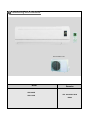
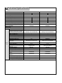
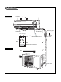
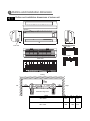
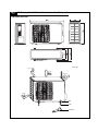
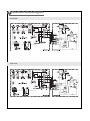
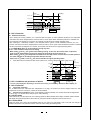
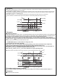
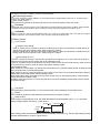
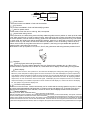
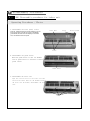
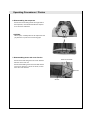
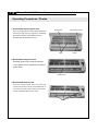
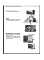
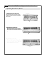
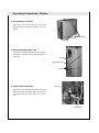
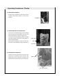
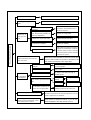
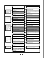
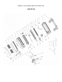
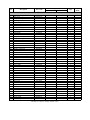
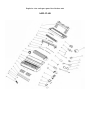
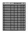
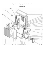
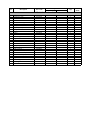
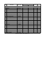
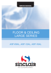
SERVICE MANUAL
KING
SERIES
ASH-09AK, ASH-13AK
1 Summary and features
09/13 Outdoor unit:
Model
ASH-09AK
ASH-13AK
Remarks
1Ph 220~240V 50Hz
R410a
2 Technical specifications
Model
ASH-09AK
COOLING
Function
Rated Voltage
ASH-13AK
COOLING
HEATING
220-240V
220-240V
50Hz
50Hz
Rated Frequency
Total Capacity (W/Btu/h)
HEATING
2650 /9050
2850/ 9730
3516/12000
4015/13700
Power Input (W)
820
785
1080
1104
Rated Input (W)
1110
1150
1500
1500
Rated Current (A)
5.69
5.9
7.6
7.6
Air Flow Volume (m3/h) (H/M/L)**
Dehumidifying Volume (l/h)
EER / C.O.P (W/W)
Energy Class
Model of Indoor Unit
Fan Motor Speed (r/min) (H/M/L)
Output of Fan Motor (w)
Input of Heater (w)
Fan Motor Capacitor (uF)
Fan Motor RLA(A)
Fan Type-Piece
Diameter-Length (mm)
Evaporator
500
580
1
1
3.21/3.61
3.26/3.64
A
ASH-09AK
A
ASH-13AK
Cool:ing 1160/1065/959/861
Heating: 1160/1067/960/860
Cool:ing 1120/1010/890/760
Heating: 1120/1010/900/780
/
1
0.263
Cross flow fan – 1
97
9
/
1
0.254
Cross flow fan – 1
φ99*644
Aluminum fin-copper tube
Aluminum fin-copper tube
7
2-1.6
7
2-1.5
576X142X145
656 x 25.4 x 304.8
MP28EC
2
3.15
MP24AA
1.5
PCB 3.15A
40/38/36/34
41/39/36/32
Pipe Diameter (mm)
Indoor
Row-Fin Gap(mm)
unit
Coil length (l) x height (H) x coil
width (L)
Swing Motor Model
Output of Swing Motor (W)
Fuse (A)
Sound Pressure Level dB (A)
(H/M/L)
Sound Power Level dB (A)
(H/M/L)***
Dimension (W/H/D) ( mm)
50/48/46/44
51/49/46/42
740 x 250 x 180
805 x 280 x 215
Dimension of Package(W/H/D)(mm)
790 x 320 x 264
860 x 355 x 280
Net Weight /Gross Weight (kg)
8/10
9/12
Model of Outdoor Unit
Compressor Manufacturer/trademark
Compressor Model
Compressor Type
L.R.A. (A)
Compressor RLA(A)
Compressor Power Input(W)
Overload Protector
Throttling Method
Starting Method
Working Temp Range (℃)
Condenser
Pipe Diameter (mm)
Rows-Fin Gap(mm)
Coil length(l) x height(H) x coil width(L)
Fan Motor Speed (rpm) (H/M/L)
Output of Fan Motor (W)
Outdoor Fan Motor RLA(A)
Fan Motor Capacitor (uF)
unit
Air Flow Volume of Outdoor Unit
Fan Type-Piece
Fan Diameter (mm)
Defrosting Method
Climate Type
Isolation
Moisture Protection
Permissible Excessive Operating
Pressure for the Discharge Side(MPa)
Permissible Excessive Operating
Pressure for the Suction Side(MPa)
Sound Pressure Level dB (A) (H/M/L)
Sound Power Level dB (A) (H/M/L)
Dimension (W/H/D) (mm)
Dimension of Package (L/W/H)(mm)
Net Weight /Gross Weight (kg)
Refrigerant Charge (kg)
Length (m)
Gas additional charge(g/m)
Connecti Outer
Liquid Pipe (mm)
on Pipe Diameter
Gas Pipe (mm)
Max
Height (m)
Distance
Length (m)
ASH-09AK
HIGHLY
ASG102CV-B7AT
Rotary
18A
4.05
875
KA-172-LYGN914
ASH-13AK
Gree
QXA-133uB030
Rotory
32
5.1
1160
B250-150-141E
Capillary
Capacitor
-5~43
-15~46
Aluminum fin-copper tube
7
1-1.6
608X495X205
830
30W
0.345
2
1400
Axial fan -1
400
Auto defrost
T1
I
IP24
7
2-1.4
731X495X25.4
850
30
0.35
2
1700
Axial fan –1
400
Auto defrost
T1
I
IP24
3
3.8
1
1.2
52
62
848X540X320
878X590X360
35/40
R410A/0.75
5
25
Φ6(1/4")
Φ9.52(3/8")
10
15
52
62
848X540X320
878X590X360
40/44
R410A/1.10
5
25
Φ6(1/4")
Φ12(1/2")
10
15
The above data is subject to change without notice. Please refer to the nameplate of the unit.
3 Part name
Indoor unit
Front Panel
Filter
Guide louver
Air in
Manual switch
Air out
Heat Cooling
LED displayer
Wall Pipe
Wrapping Tape
LED displayer
Wireless remote control
Set Temp
DRY
Run
Remote control window
Outdoor unit
Connection pipe
Air in
Drainage hose
Air out
4 Outline and installation dimension
Outline and installation dimensions of indoor unit
H
Air inlet
D
W
Tube exit
Wall-Mounting Plate:
ASH-09AK
ASH-13AK
Rear View
Ceiling
Left
Right
Wall-Mounting Plate
Model
W(㎜)
H(㎜)
D(㎜)
ASH-09AK
740
250
180
ASH-13AK
805
280
215
Outline and installation dimensions of outdoor unit
ASH-09AK, ASH-13AK
Unit:mm
over
over
over
over
Bolt
Nut
Wrench
5 Electrical circuit diagram
ASH-09AK
ASH-13AK
6
Manual of functions of remote controller and operation method
Manual 1 of functions of remote controller
6.1.1 Temperature parameter
The room setting temperature(Tpreset)
The room ambient temperature (Tamb)
6.1.2Basic Functions
Once energized, the compressor should in no way be restarted unless after 3-minute time interval at least. For the first
energization, the compressor will be started without 3-minute lag. The compressor, once started,will not be stopped
within 6 minutes with the change of room temperature.
Cooling Mode
Cooling Conditions and Process
When T amb.≥Tpreset +1℃, the unit will run under cooling mode, in which case the compressor and outdoor fan will start
and the indoor fan will run at setting speed.
When T amb.≤Tpreset -1℃, the compressor and the outdoor fan will stop, the indoor fan will run at setting speed.
When Tpreset -1℃<T amb.< Tpreset +1℃, the unit will maintain its original operating status.
Under this mode, the switchover valve will not be powered on, and the setting temperature range is16 ~30 .
Tpreset +1℃
Start cooling
Tamb
Original operating status
Tpreset -1℃
≥6 min.
≥3 min.
≥6 min.
Stop cooling
Compressor
Outdoor fan
Indoor fan
Preset speed
6.1.2.1.3 Protection
Run
Stop
Antifreeze Protection
If it is detected that the system is under antifreeze protection, the compressor and outdoor fan will be stopped,
and the indoor fan will run at setting speed. When antifreeze protection is released and the compressor has stopped
for 3 minutes, the unit will resume its original operating status.
During antifreeze protection
3 min.
Compressor
Outdoor fan
Preset speed
Indoor fan
6.1.2.2 DRY Modes
Run
Stop
6.1.2.2 .1 The conditions and process of DRY
When T amb. > T preset+2℃, the unit will run under DRY cooling mode, in which case the compressor and outdoor fan
will be started and the indoor fan will run at low speed.
When Tpreset -2℃≤T amb.≤Tpreset +2℃, the unit will run under DRY mode, in which case the indoor fan will keep run
at low speed, the compressor and the outdoor fan will be stopped after 6 minutes . After 4 minutes,the compressor
and the outdoor fan will be restarted. The dehumidifying process is so repeated in cycle.
When Tamb.< Tpreset-2℃, the compressor and outdoor fan will be stopped, the indoor fan will run at low speed.
Under this mode, the switchover valve will not be powered on, and the setting temperature range is16 ~30 .
.
Tpreset +2℃
Cooling
Tamb
Dry
Tpreset -2℃
6 min.
Stop
6 min.
4 min.
4 min.
Compressor
Outdoor fan
Indoor fan
low speed
Stop
Run
6.1.2.2.3 Protection
Antifreeze Protection
Upon meeting the cooling condition, if it is detected that the system is under antifreeze protection, the compressor
and outdoor fan will be stopped,and the indoor fan will run at low speed. When antifreeze protection is released and
the compressor has stopped for 3 minutes, the complete unit will resume its original operating status.
Upon meeting the dehumidify condition, if it is detected that the system is under antifreeze protection, the com
-pressor and outdoor fan will be stopped,and the indoor fan will run at low speed. When antifreeze protection is released
and the compressor has stopped for 4 minutes, the complete unit will resume its original operating status.
6.1.2.3 HEAT Mode (there is no this mode for cooling only unit)
6.1.2.3 .1The conditions and process of heating
When Tamb Tset +2 ,the system enters heating running, in this case, the reversal valve, compressor,
outer fan enter simultaneously running.The indoor fan will delay at most for 2min to run.
When Tamb Tset +4 ,the compressor and outdoor fan will stop, but the reversal valve is still with power on,
the indoor unit will run at setting fan speed for 60s then will stop .
When Tset +2 <Tamb < Tset +4 ,the unit will maintain its original operating status.
Under this mode, the switchover valve will be powered on, and the setting temperature range is16 ~30 .
Stop heating
Tset
Original running state
Tset
Start heating
Tamb.
6Min.
3Min.
6Min.
Compressor
Outer fan
Inner fan
2Min.
Setting
fan speed
2Min.
Setting
fan speed
Reversal valve
Running
6.1.2.3.3 Conditions and processes of defrost
Stop
This unit adopt intelligent defrosting,it can defrost according to the frosting conditions,dual 8 display H1
6.1.2.3.4 Protection
High Temp. Protection
If it is detected that the evaporator tube temperature is too high, the outdoor fan will be stopped. When the tube
temperature resumes to normal, the outdoor fan will be restarted.
Noise Silencing Protection: If the unit is stopped by pressing ON/OFF, the reversal valve will be stopped after
2-minute lag; or 2 minutes will be delayed upon mode switching.
6.1.2.4 Fan mode
Under FAN mode, only the indoor fan runs at setting speed.The RUN indicator will be bright. Double 8 module indicator
will display the setting temperature. When stand by, the power indicator is bright but the unit does not run.
6.1.2.5 Auto Mode
Under this mode, the system will automatically select its run mode (cool, dehumidify, heat or fan) with the change of
ambient temperature. For protection function, same as under cooling and heating mode.
3.Other controls
1. Memory function
Memory contents: Mode, up and down swing, Light, Setting temp., Setting fan speed, Ordinary setting
Fahrenheit/Centigrade, after powered off, and powered on, it will run at the memory contents.
If no timer setting function in last remote control order, the system will memorize the last remote control
order, the system will memorize the last remote control order and work with last remote control setting.
In the last remote control order, there is ordinary timer function, if power off happen beffore the timer
arrived, the system will memorize the last remote control timer function, and will recalculate.
If there is timer function in last remote control order, but timer has arrive, system will run at timer on or timer
off and power off, after repowered on, the system will run at the mode before power off.
Timer function
1.Ordinary Timer setting:
Timer on: Under unit off, the timer on function could be set up, if timer on has arrived, controller will run at
setting mode, the timer interval is 0.5hr, setting range is 0.5-24hrs.
Timer off: Under unit off, the timer off function could be set up, if timer off has arrived, controller will run at
setting mode, the timer interval is 0.5hr, setting range is 0.5-24hrs.
Timer setting for hour:
Timer on: if system is running, to set timer on, the system will continue to run, if unit is off to set up timer on,
when timer on has arrived, the system will run at pressetting mode.
Timer off: If system is off to set up the timer off, when to set up timer off, the unit will stand by, when unit is on,
to set up timer off, when the timer off arrived, the system will stop to work.
Timer setting change:
When system is in Timer status, can set up timer on and timer off by wireless remote control, to reset up Timer
also, the system will run at last setting status.
When system is running, at the same time to set up Timer on and Timer off, the system will keep the present
setting status, when time arrived, system will stop to work.
When system stop, at the same time to set up Timer on and Timer off, the system will stop, untile the timer
arrived, the system will start to work.
Hereafter, when timer of timer on in every day arrived, it will run the presetting modes, after timer off arrived,
the system will stop.
(3) Auto button
After powered on, press this button, it will run at Auto mode, when repressed, the unit will turns off.
(4) Buzzer
The controller is powered on and detect the signal received, the buzzer will beep.
(5) Sleep function
Under cooling or dehumidifying mode, the preset temperature will automatically rise by 1 , ine hour after
setting of sleep program and rise by 1 after 2hours.
Under heating mode, the preset temperature will automatically decrease by 1
program and decrease by another 1 after 2hours.
one hour after setting of sleep
(6) Turbo function
The turbo function is available in Cool and Heat modes.
(7) Dry function
Dry function is available in Cool and Dehumidifying modes.
(8) Auto fan speed control
In this mode, indoor fan can run with Hig, Mid, Low speeds.
(9) Up and down swing control
After powered on, the lower swing motor will firstly rotate the guide louver to position 0, close up the air outlet
vent; After unit turned on, if to set up swing function, when indoor fan stop running, the guide louver will stop
at current position, inner fan motor is running, guide louver will resume to swing.From Cool, Dry, Fan modes
to Heat mode, the guide louver will be opened at D position, when turn on swing will run at (A-D); from Heat
mode to Cool, Dry, Fan mode, the fan louver will turn to B position, if turn on the swing, it will run at (A-C).
(10) Displayer
Running figure and mode figure display
After powered on, the figure will be displayed, then only Power/running indicator turn on. When using
remote conroller to open the unit, it will turn on, at the same time to display current setting running modes.
Dual 8 display
When the unit is turned on, after powered on, the nixie tube will display the setting temp.(setting range is 1630 ). Under Auto mode, cooling and fan will display 25 , heating will display 20 , cooling only control
display 25 .
LCD Display
When cooling and dehumidifying, the Cool and indicator will turn on, when heating, the Heat and Run indicaor
will turn on, when in fan mode, the indicator will turn on.
(11) PG motor lock protection
When turn on the fan motor, if motor continuously run for a while and the running speed is very slow, in order
to prevent motor automatically self-protection, it will stop running and display lock; If currently turns unit on,
that dual 8 will display lock error code H6; If current is unit off, will not display the block error information.
Manual 2 of functions of remote controller
This manual is applicable to 18K, 24K models, the centigrade is used for the following function manual, if there will be the Fahrenheit
degree, that will be TF= TCX1.8+32.
1. Temperature parameter
The room setting temperature(Tpreset)
The room ambient temperature (Tamb)
Basic Functions
Once energized, the compressor should in no way be restarted unless after 3-minute time interval at least for the first energization, the
compressor will be started without 3-minute lag. The compressor, once started, will not be stopped within 6 minutes with the charge of
room temperature.
Cooling Mode
Cooling Conditions and Process
When Tamb. Tpreset 1 , the unit will run under cooling mode, in which case the compressor and outdoor fan will start and
the indoor fan will run at setting speed.
When Tamb. Tpreset 1 , the compressor and the outdoor fan will stop, the indoor fan will run at setting speed.
When Tpreset 1
Tamb. Tpreset 1 , the unit will maintain its original operating status.
Under this mode, the four-way valve will not be powered on and the setting temperature range is 16-30
The displayer displays running signal, cooling signal and setting temperature.
amb.
.
Start cooling
Preset
Original operating status
Preset
Stop cooling
min.
min.
min.
Compressor
Outdoor fan
Indoor fan
Preset speed
Run
Stop
Protection
Antifreeze Protection
If it is detected that the system is under antifreeze protection, the compressor and outdoor fan will be stopped,
and the indoor fan will run at setting speed. When antifreeze protection is released and the compressor has
stopped for 3 minutes, the unit will resume its original operating status.
During antifreeze protection
Compressor
3 min.
Outdoor fan
Indoor fan
Preset speed
Run
Over current protection
Stop
If it is detected that the system amperage exceeds the specified value(about 22 A), the main unit will enter into the status
that only the fan is running. After 3 minutes and overcurrent protection is released, the main unit will resume its original
operating status .If it is 6 times continuously detected overcurrent protection (if the compressor has run over 6 mins continuously,
the times of protection will be cleared),the main unit will be stopped on standby,the nixietube will display error code "E5",
power indicator will blink and it is need to restart the unit by the wireless remote control.
DRY Modes
DRY Modes
When Tamb. Tpreset 2 , the unit will run under DRY cooling mode, in which case the compressor and outdoor fan will
be started and the indoor fan will run at low speed.
When Tpreset 2
Tamb. Tpreset 2 , the unit will run under Dry mode, in which case the indoor fan will keep run at low speed,
the compressor and outdoor fan will be stopped after 6mins. After 4 minutes, the compressor and outdoor fan will be restarted. The
dehumidifying process is so repeated in cycle.
When Tamb. Tpreset 2 , the compressor and outdoor fan will be stopped, the indoor fan will run at low speed.
Under this mode, the switchover valve will not be powered on and the setting temperature range is 16-30 .
Tamb.
Start cooling
Tpreset
Dehumidifying
Tpreset
min.
min.
min.
Stop running
min.
Compressor
Outdoor fan
Indoor fan
Preset speed
Stop
Run
Protection
Antifreeze Protection
Under dehumidifying and cooling mode, i f it is detected that the system is under antifreeze protection, the compressor and
and outdoor fan will be stopped, and the indoor fan will run at low speed. When antifreeze protection is released and the
the compressor has stopped for 3 minutes, the complete unit will resume its original operating status.
Upon meeting "run 6 mins and stop 4 mins" dehumidify condition, i f it is detected that the system is under antifreeze
protection,the compressor and outdoor fan will be stopped, and the indoor fan will run at low speed. When antifreeze protection is released and the compressor has stopped for 4 minutes, the complete unit will resume its original operating
status.
The other protections are the same with that under Cool mode.
Other protection
HEAT Mode (there is no this mode for cooling only unit)
The conditions and process of heating
When Tamb Tset 2 ,the system enters heating running, in this case, the reversal valve, compressor,
outer fan enter simultaneously running.The indoor fan will delay at most for 2min to run.
When Tamb Tset 4 ,the compressor and outdoor fan will stop, but the reversal valve is still with power on,
the indoor unit will run at setting fan speed for 60s then will stop .
When Tset 2
Tamb Tset 4 ,the unit will maintain its original operating status.
Under this mode, the switchover valve will be powered on and the setting temperature range is 16-30
.
Stop heating
Tpreset
Original running state
Tpreset
Tamb.
6Min.
Start heating
3Min.
6Min.
Compressor
Outer fan
Inner fan
Setting
fan speed
2Min.
Setting
fan speed
2Min.
Inner fan
Running
Conditions and processes of defrost
Stop
This unit adopt intelligent defrosting,it can defrost according to the frosting conditions,dual 8 display H1
Protection
Anti-high temperature protection
If it is detected that the evaporator tube temperature is too high, the outdoor fan will be stopped. When the tube
temperature resumes to normal,the outdoor fan will be restarted.
Noise Silencing Protection
If the unit is stopped by pressing ON/OFF, the reversal valve will be stopped after 2-minute l ag; or 2 minutes wi l l be
delayed upon mode switching.
Over current product
The overcurrent protection is the same with the the over current protection under cool mode.
Fan mode
Under FA N mode, only the indoor fan runs at setting speed.The RUN indicator will be bright. Double 8 module indicator
will display the setting temperature. When stand by, the power indicator is bright but the unit does not run.
Auto Mode
Under this mode, the system will automatically select its run mode (cool, dehumidify, heat or fan) with the change of
ambient temperature. For protection function, same as under cooling and heating mode.
Other controls
Timer function
Ordinary Timer setting:
timer on: Under unit off, the timer on function could be set up, if timer on has arrived, controller will run at
setting mode, the timer interval is 0.5hr, setting range is 0.5-24hrs.
Timer off: Under unit off, the timer off function could be set up, if timer off has arrived, controller will run at
setting mode, the timer interval is 0.5hr, setting range is 0.5-24hrs.
Timer setting for hour:
Timer on: if system is running, to set timer on, the system will continue to run, if unit is off to set up timer on,
When timer on has arrived, the system will run at pressetting mode.
Timer off: If system is off to set up the timer off, when to set up timer off, the unit will stand by, when unit is on,
to set up timer off, when the timer off arrived, the system will stop to work.
Timer setting change:
When system is in Timer status, can set up timer on and timer off by wireless remote control, to reset up Timer
also, the system will run at last setting status.
When system is running, at the same time to set up Timer on and Timer off, the system will keep the present
setting status, when time arrived, system will stop to work.
When system stop, at the same time to set up Timer on and Timer off, the system will stop, untile the timer
arrived, the system will start to work.
Hereafter, when timer of timer on in every day arrived, it will run the presetting modes, after timer off arrived,
the system will stop.
Auto button
After powered on, press this button, it will run at Auto mode, when repressed, the unit will turns off.
Buzzer
The controller is powered on and detect the signal received, the buzzer will beep.
Sleep function
Under cooling or dehumidifying mode, the preset temperature will automatically rise by 1 , ine hour after
setting of sleep program and rise by 1 after 2hours.
Tpreset
Preset temp. Tpreset
Tpreset
Tpreset
1hour
2hours
2hours above
Under heating mode, the preset temperature will automatically decrease by 1
program and decrease by another 1 after 2hours.
one hour after setting of sleep
1hr.
2hrs.
2hrs. above
Tpreset
Tpreset
Tpreset temp.
Tpreset
Turbo function
The turbo function is available in Cool and Heat modes.
Dry function
Dry function is available in Cool and Dehumidifying modes.
Auto fan speed control
In this mode, indoor fan can run with Hig, Mid, Low speeds.
Up and down swing control
After powered on, the lower swing motor will firstly rotate the guide louver to position 0, close up the air outlet
vent; After unit turned on, if to set up swing function, when indoor fan stop running, the guide louver will stop
at current position, inner fan motor is running, guide louver will resume to swing.From Cool, Dry, Fan modes
to Heat mode, the guide louver will be opened at D position, when turn on swing will run at (A-D); from Heat
mode to Cool, Dry, Fan mode, the fan louver will turn to B position, if turn on the swing, it will run at (A-C).
When unit is turned off, the guide louver will turn to position 0, the swing is only available after preset the
swing function, and indoor unit is running.
Note: When to set up at position L to B, A to C, B to D, the guide louver will swing between position W to D.
Displayer
Running figure and mode figure display
After powered on, the figure will be displayed, then only Power/running indicator turn on. When using
remote conroller to open the unit, it will turn on, at the same time to display current setting running modes.
Dual 8 display
When the unit is turned on, after powered on, the nixie tube will display the setting temp.(setting range is 16-30 ).
When the preset temperature display signal has been received, the nixie tube will display the preset temperature;
If the display ambient temperature signal has been received, the nixie tube will display the current indoor ambient
temperature, if to set up others by remote controller that the display will maintain its status. At displaying ambient
temperature, the unit received the remote control signal, it will display 5s preset temperature then turn to ambient
temperature display. The ambient temperature sensor malfunction will display F1; Indoor tube sensor will display
F2, wire jumper cap protection displays C5.
PG motor lock protection
When turn on the fan motor, if motor continuously run for a while and the running speed is very slow, in order
to prevent motor automatically self-protection, it will stop running and display lock; If currently turns unit on,
that dual 8 will display lock error code H6; If current is unit off, will not display the block error information.
Power-off Memory
Memory contents: Mode, UP/DOWN Swing, light, Set temp, Set fan speed.
After de-energized, and re-energized, the unit will start to run with the memory function automatically. The system, if the last
remote control signal do not set timer function, will memorize the last remote control signal and run according to it. If the last
remote control signal has set timer function, the system is de-energized before the set time,when re-energized, the system
will memorize the timer function, the set time will recalculate. If the last remote control signal has set timer function and the
system is de-energized after the set time, when re-energized, the system will memorize the running status before de-energized.
7 Dissassembly Procedures
(09) Disassembly procedures for indoor unit
Operating Procedures / Photos
1. Disassemble the front panel, filter
Push the rotating shaft of front panel outsidely to put out
it from the groove, screw off one screw on the display
guard board, then take down the displayer connection
wire, can take down the front panel.
Front Pane
Screw
Filter
2. Disassemble the guide louver
Bend the guide louver so that the movable
lock of guide louver is released to remove the
guide louver.
Guide louver
3. Disassemble the front case
Open the 2 screw covers at the front case and
screw off 4 screws. Pull out the movable latch at
the front case with hand, disassemble the front
case.
Screw
Protect board
Operating Procedures / Photos
4. Disassemble the electric cover
Screw off the screw, then press the clasps in by
Screw
till they loose, then lift up wards the electric cover.
Electric cover
5. Disassemble the electric box
Clasp
Grounding wire
Screw off the grounding wire of the evaporator,
remove the temperature sensor for the pipe, put
Tube Sensor
out the connection lines for the step motor and
the indoor motor. Screw off the screw fixing the
electric box. Remove the electric box.
Screw
5. Disassemble water tray
Connector
Loosen the clasps at both sides of water tray sub-assy then lift them up,
can take out of the water tray sub-assy.
Note:Because the water tray is connected with the water drainage pipe,
so when take it out should pay more attention, avoid to hurt the fin of
evaporator.
Clasp
Water tray
Clasp
Operating Procedures / Photos
6. Disassembling the evaporator
Screw off one screw which fix the connection pipe clamp.
Take off the connection pipe clamp.
Screw
CAUTION:
When repair, Carefully take out the evaporator and
pay attention to protect the connecting pipe.
Screws
7. Disassembling motor and cross flow fan
Screw off 4 screws fixing the motor cover and then
take the motor cover out.
Motor Press Plate
Screw off the holding screw at the left shaft sleeve
of the cross flow fan, pull out the motor, and remove the cross flow fan.
Screws
Screws
(12) Disassembly procedures for indoor unit
Operating Procedures / Photos
1. Disassemble the front panel, filter
Open the front panel ,Push the filter upwards to
unloose the clasp, and then pull out the two filters.
Front Pane
Screw off one screw on the displayer
box, take down the guard board then
disconnect the displayer connection
wire, can take down the front panel.
Display Cover
Screw
Filter
2. Disassemble the guide louver
Bend the guide louver so that the movable
lock of guide louver is released to remove the
guide louver.
Guide louver
3. Disassemble the front case
Open the 2 screw covers at the front case and
screw off 4 screws. Pull out the movable latch at
the front case with hand and then pull it backwards to disassemble the front case.
Screw
Operating Procedures / Photos
4. Disassemble the electric cover
Press the clasps in by till they loose, then lift up
wards the electric cover.
Electric cover
5. Disassemble the electric box
Screw off the grounding wire of the evaporator,
remove the tube sensor and temp sensor support,
Temp Sensor Support
Grounding wire
Tube Sensor
put out the connection lines for the step motor
and the indoor motor. Screw off the screws fixing
the electric box. Remove the electric box.
Connector
5. Disassemble water tray
Loosen up the clasp at the front of and the rear of
water tray sub-assy and lift them up, can take out
the water tray sub-assy.
Note: Due to the water tray is connected with the
water drainage pipe, please pay more attention do
not to damage the fin on evaporator.
Claslp
Water tray
Clasps
Operating Procedures / Photos
6. Disassembling the evaporator
Screw off 4 screws fixing the left and right side of
the evaporator, then elevate left side the evaporator to remove it backward.
CAUTION:
When repair, Carefully take out the evaporator and
pay attention to protect the connecting pipe.
Screws
7. Disassembling motor and cross flow fan
Motor Press Plate
Screw off 4 screws fixing the motor cover and then
take the motor cover out.
Screw off the holding screw at the left shaft sleeve
of the cross flow fan, pull out the motor, and remove the cross flow fan.
Screws
Screws
(Conventional 09) Disassembly procedures for indoor unit
Operating Procedures / Photos
1. Disassemble the front panel, filter
Push the rotating shaft of front panel outwards to
unloose the clasp, and then pull out the front panel.
Front Panel
Electric Box Cover
Screw off the screws of the electric box cover,
and take down the electric box cover.
Filter
2. Disassemble the guide louver
Bend the guide louver so that the movable
lock of guide louver is released to remove the
guide louver.
Guide louver
3. Disassemble the front case
Open the 2 screw covers at the front case and
screw off 4 screws. Pull out the movable latch at
the front case with hand and then pull it backwards to disassemble the front case.
Screws
Screw
Operating Procedures / Photos
4. Disassemble the electric box cover
Screw off the screw, then press the clasps in by
till they loose, then lift up wards the electric cover
and the light board.
Light Board
Screw
Electric box cover
5. Disassemble water tray
Loosen up the clasp at the front of and the rear of
water tray sub-assy and lift them up, can take out
the water tray sub-assy.
Connector
Note: Due to the water tray is connected with the
water drainage pipe, please pay more attention do
not to damage the fin on evaporator.
Water tray
Claslp
6. Disassemble the electric box
Loosen the grounding wire of the evaporator, remove the temperature sensor for the pipe, put
Grounding wire
Tube Sensor
out the connection lines for the indoor motor.
Screw off the screws fixing the electric box. Remove the electric box.
Screw
Connector
Operating Procedures / Photos
7. Disassembling the evaporator
Screw
Screw off 1 pc screw fixing the connecting pipe
clamp, take down the connecting pipe clamp.
CAUTION:
When repair, Carefully take out the evaporator and
pay attention to protect the connecting pipe.
Screws
8. Disassembling motor and cross flow fan
Screw off 4 screws fixing the motor cover and then
take the motor cover out.
Motor Press Plate
Screw off the holding screw at the left shaft sleeve
of the cross flow fan, pull out the motor, and remove the cross flow fan.
Screws
Screw
(Conventional 12) Disassembly procedures for indoor unit
Operating Procedures / Photos
1. Disassemble the front panel, filter
Push the rotating shaft of front panel outwardly,
Front Panel
to make it out of the groove, then can take down
the front panel.
Filter
2. Disassemble the guide louver
Bend the guide louver so that the movable
lock of guide louver is released to remove the
guide louver.
Guide louver
3. Disassemble the front case
Open the 2 screw covers at the front case and
screw off 1 screws. Pull out the movable latch at
the front case with hand and then pull it backwards to disassemble the front case.
Screws
Operating Procedures / Photos
4. Disassemble the Light Board and electric cover
Screw off 1pc screw of light board, then
can take down the light board.
Light Board
Electric cover
5. Disassemble the electric box
Lossen the grounding wire of the evaporator, remove the tube sensor and temp sensor support,
Grounding wire
put out the connection lines for the step motor
and the indoor motor. Screw off the screws fixing
Temp Sensor Support
Tube Sensor
the electric box. Remove the electric box.
6. Disassemble water tray
Unloosen the clasps of front and rear sides of water tray,
then lift them up, then can take down the water-tray
sub-assy, and pay more attention do not hurt the fin
on evaporator.
Connector
Clasp
Water tray
Clasps
Operating Procedures / Photos
7. Disassembling the evaporator
Screw off 4 screws fixing the left and right side of
the evaporator, then elevate left side the evaporator to remove it backward.
CAUTION:
When repair, Carefully take out the evaporator and
pay attention to protect the connecting pipe.
Screws
8. Disassembling motor and cross flow fan
Motor Press Plate
Screw off 4 screws fixing the motor cover and then
take the motor cover out.
Screw off the holding screw at the left shaft sleeve
of the cross flow fan, pull out the motor, and remove the cross flow fan.
Screws
Screw
(09/12) Disassembly Procedures for Outdoor Unit
Operating Procedures / Photos
1. Disassemble Big Handle
Unscrew the screw fixing the big handle,and then
remove it downwards to take it out.
Screw
2. Disassemble Top Cover
Unscrew the 2 screws fixing left side of top cover
and the 1 screw fixing the right side to remove the
top cover.
Screws
3. Disassemble Rear Grill
Unscrew the 4 screws fixing the rear grill to remove it.
Rear Grill
Screws
Big Handle
Operating Procedures / Photos
4. Disassemble Front Panel
Unscrew the 5 screws fixing the panel and
dextrorotate the front panel to pull it out from
groove.
Screws
5. Disassemble Right Side Plate
Unscrew the 2 screws fixing electric box ,and then
unscrew the 5 screws fixing the right side plate to
remove it.
Screws
Right Side Plate
Screws
6. Disassemble Electric Box
Screw
Unscrew the screws fixing the electric box, and
then pull out the inset block of lead-out wire of
compressor and fan motor to take out the electric
box.
Electric Box
Operating Procedures / Photos
7. Disassemble Axial Flow Fan
Loosen the fastening nut fixing the axial flow fan
with a spanner, and then take out the nut, spring
Axial Flow Fan
gasket and flap gasket in turn.
Nut
8. Disassemble Motor and Motor Support
Unscrew the 4 screws fixing the motor to take out
the motor,and then unscrew the 2 screws fixing the
motor support to take it out.
Screws
Motor
Screws
9. Disassemble Four-way Valve
Unscrew the fastening nut of the four-way valve
coil and remove the coil. Wrap the four-way valve
with wet cotton and unsolder the 4 weld spots
Four-way valve
connecting the four-way valve to take it out. (Note:
Refrigerant should be discharged firstly.)
Four-way valve coil
Welding process should be as quick as possible
and keep wrapping cotton wet all the time. Be
sure not to burn out the lead-out wire of
compressor.
Weld spots
Operating Procedures / Photos
10. Disassemble Capillary
Respectively unsolder the weld spots of main
capillary and auxiliary capillary to take off the
capillary.
Capillary
11. Disassemble Gas and Liquid Valves
Unscrew the two bolts fixing gas valve and liquid
valve.Unsolder weld spots between gas valve and
and air-return pipe to remove the gas valve.
Unscrew the two bolts fixing liquid valve. Unsolder
weld spots between liquid valve and capillary to
remove the liquid valve.
(Note:During unsoldering ,wrap the valves with
Liquid Valve
Bolts
wet cloth to avoid damage for high temperature.)
Gas Valve
12. Disassemble Compressor
Unscrew the three foot-nuts at the foot of the
compressor. Unsolder the suction and the discharge pipes of the compressor,and then carefully remove the pipes to take out the compressor.
Weld spots
Nuts with washers
9 Failure and analysis
Note: When replacing the controller, make sure insert the wire jumper into the new controller, otherwise, the running indicator off 3s,
blink 15 times, (the dual eight will display C5) but cannot turn on the unit.
The breaker trips at once when it
Measure insulation resistance to ground to see
if there is any leakage.
is set to "ON".
Trip of breaker or blow
of fuse
The circuit or the part of the air conditioner has
malfunction. They heat and break the insulation
The breaker trips in few minutes
when it is set to "ON"
and lead to short circuit or creepage. Measure
the insulation resistance or eliminate the malfunction one by one. If the breaker itself has
Air conditioner can not start up
malfunction, then replace the breaker.
The air conditioner
No power
Check power supply circuit.
Power plug is not well plugged in and poor connection
Check if the plug is properly plugged in and
make the loose contact firm.
does not react after
it is powered ( after
Fuse of controller burnt out
Change controller fuse
the plug is inserted,
the buzzer does
The transformer connection is loose or has bad
not sound and the
contact or the transformer has malfunction
remote startup has
Fasten the wiring; measure the output
voltage of the transformer, if it is
incorrect, change the transformer
no response)
The remote controller
Controller is broken
Check remote controller
Remote controller is short of power
Change batteries
Remote controller malfunction
First, press the manual switch button AUTO,
does not receive
signals (after it is
powered, the buzzer
above methods. If it runs normally after
will sound, unless it
has
if there is no response,check based on the
Receiver loose or poor connection
malfunction)
pressing the button,check again whether the
installation position and the connection wire
of the reception head is correct. If it is
Receiver is broken
Power voltage is too low
correct,then replace the receiver or the remote controller.
heck the voltage. If it is lower than 10£¥ of the rated voltage, check the
cause, improve the power supply condition and add the stabilized voltage
power supply.
Controller malfunction (IC2003 broken,
creepage of
parallel capacitor of relay loop,
relay is broken etc.)
In cool, heat mode,the
outdoor
unit and compressor
will not run.
Change controller
Wire loose or wrong connection
Correctly wire according to the drawing
Improper setting of temperature
Adjust setting temp.
Improper set of temperature
Adjust set temperature
If cooling (heating) load is
proper
Check the forecasted load of cooling (heating)
The refrigerant has leakage or is
insufficient
Malfunction of
refrigerant
flow
Leakage between the high pressure and the low pressure inside the compressor
Malfunction of four-way valve
Poor COOL(HEAT) operation
Local block of capillary
Blockage of cooling system
Heat insulation for the connection
pipes of the indoor unit and the outdoor unit is bad.
heck and fill the leakage, then
vacuumize it and supplement the refrigerant as required
Replace the compressor
Replace the four-way valve
Replace the capillary
Judge whether the system is blocked by
observing the condensation of evaporator and the pressure value of the high
pressure manometer and take measures
to deal with the system.
Make sure that heat insulation for the thick and thin pipes
is good. Heat insulation must also be provided for the
joint andthe exposed part of the copper pipe .
Block of outdoor heat exchanger
Clean the dust accumulated on the surface of
the heat exchanger.
Air filter were blocked
Clean the filter
Fan speed was set too slow
Air circulation
is insufficient
Fan rotation speed becomes
low
The installation position of the
outdoor unit is not appropriate.
The outdoor temperature is too high.
The air tightness is not enough. People
come in and out too frequently. There
are heating devices indoors.
To set the fan speed to high or
middle speed
Capacitor
damage
Replace the capacitor
Motor damage
Replace the motor
Good ventilation must be provided for the
installation position of the outdoor unit.
Properly install the rainproof plate or the sunproof plate. If the
maximum cool air still can not meet the requirement, it is suggested to replace the air conditioner.
Keep certain air tightness indoors, try not to use
electricalappliance with large quantity of heat
The indoor fan motor is burned or breaks
or has the heat protector malfunction.
The fan does not
run when it is set
to supply air.
In the cooling and
heating mode, the
compressor runs,
but the outdoor fan
does not run.
The compressor is too hot
and leads to
the action of the
protector.
The built-in heat protector of the motor
breaks frequently because the motor
is abnormal.
Replace the fan motor
Wrong connection
Make the correction connection based on the
circuit drawing.
The fan capacitor has open circuit or is
damaged.
Replace the fan capacitor of the same type
and same specification.
The outdoor fan motor is damaged.
Replace the fan motor
Wrong connection
Make the correct connection based on the
circuit drawing
The outdoor fan capacitor is damaged.
Replace the fan capacitor
Malfunction of compressor
Replace the compressor
Breakage of running capacitor of
compressor
Replace the capacitor
The voltage is too low or too high.
Manostat is recommended.
Wrong wire connection
Connect the circuit diagram correctly
The protector itself has malfunction.
The refrigerant is not enough or is too
much.
The compressor is too hot
and leads to the
action of the
protector.
Replace the fan motor or the defective part.
The capillary is blocked and the temperature rises.
The compressor does not run
smoothly or is stuck. The air discharge valve is damaged
The protector itself has malfunction.
Use the multimeter to check whether the contact of the compressor is on when it is not
overheated. If it is not on, then replace the protector
Adjust the volume of the refrigerant
Replace the capillary
Replace the compressor
Replace the protector
The torque of the swing motor is not
enough
The swing fan
does not run.
Wrong connection
The controller is damaged(IC2003 is
damaged, the swing relay can not
close, etc)
First, check whether the connection is
wrong. If no, replace the parts
Drainage pipe blocked or broken
Change drainage pipe
Water leakage
Wrap of refrigerant pipe joint is not close
enough.
Re-wrap and make it tight.
Fan of indoor unit contacts other parts.
Adjust fan location.
Foreign object in indoor unit
Take out the foreign object.
Compressor shakes too much.
Abnormal sound
and shake
Adjust support washer of compressor, and
tighten loosen screws.
Touch of pipeline of outdoor unit
Separate the touching pipeline.
Touch of inner plates
1. Tighten connect screw.
2. Stick absorbing clay between plates.
Louver of outdoor unit touched outer
case.
Adjust location of louver.
Abnormal sound inside compressor
Change compressor
Abnormal solenoid sound from 4-way
valve when heating
Circuit-short inside solenoid of the valve
and change the solenoid valve.
There are no heating malfunctions in the above for the cooling only unit.
PG motor locked protection H6:
Probable reasons:
1. Air vents were blocked which may cause the fan speed is too slow;
2. Fan blade locked;
3. Motor locked;
4. Fan motor capacitor damaged;
5. Motor damaged (ordors, winding, open circuit or shortcircuit are not normal, when testing the winding, pls distinguish
whether the motor body cause temperature is too high so that bring on the thermal protector starts up)
6. IC board damaged (during normally running, there are voltage at both capacity input and output)
7. Mainboard damaged.
8. Motor thermal protection.
Disposal methods:
1. Remove the obstruction;
2. Reassembling;
3. Replace motor;
4. Replace capacitor;
5. Replace motor;
6. Replace circuit board;
7. Replace mainboard;
8.Under the normal circumstances, the motor will not act, but in other circumstances, such as evaporator is very dirty, to much dust
attached on the fan blade that will cause the motor overload running, so that during the operation, frequent thermal protection will
happen, so it is need to be cleaned or replaced.
PARTS GUIDE
KING SERIES
ASH-09AK, ASH-13AK
Contents
04..………………………………….......................................................ASH-09AK Indoor unit
06..…………………………………………………………………...…ASH-13AK Indoor unit
08..…………………………………………………………………....ASH-09AK Outdoor unit
10..………………………………………………………………........ASH-13AK Outdoor unit
Explosive view and spare parts list of indoor unit
ASH-09AK
No.
Description
Part Code
Updated
Date
Part code
Qty
ASH-09AK Indoor Unit
1
2
3
4
5
6
7
8
9
10
11
12
13
14
15
16
17
18
19
20
21
22
23
24
25
26
27
28
29
30
31
32
33
34
35
36
37
38
39
40
41
42
43
44
45
46
47
48
Wall-Mounting Frame
Rear Case
Evaporator Pipe Cover
Drainage Pipe
Pipe Clamp
Cross Flow Fan
Fan Bearing
Ring of Bearing
Water Tray
Swing Louver
Swing link
Manual Lever
Evaporator Assy
Evaporator Support
Cable clamp
Front Case
Screw Cover
Decorating board
Front Panel
Border of front lid
Filter
Guide Louver
Guide Louver Bearing
Remote Controller
Magic mirror
Decorating ring
Display board
Protect board
Cover plate
Main PCB
Fuse 3.15A 250VAC
Room Sensor
Tube Sensor
Sensor insert
Stepping Motor MP28EA
Motor FN20E-PG
Motor Clamp
Wire Clip
Wire Clamp
Receiver Board (5bit)
Electric Box Cover
Cover of shielding case
Electric Box
Shielding case
Transformer 41X26.5E
Connecting Cable
Power Cord
Connecting Cable
01252220
222020572
06122001
05230014
24242004
10352001
/
76512203
2018205201
10512079
10582052
10582027
010021276
24212058
71010002
2000298601S
242520042
20192041
200025781
20192042
11122002
105120782
10542011
30510041
68014004
20192028
30540016
26112102
22242056
30135070
46010014
390001912
390000591
42020063
15212002
150120761
26112080
26112082
26112121
42010262
20112015
01592054
20112017
01592008
43110231
40020536
400220111
40020540
The data are subject to change without notice.
1
1
1
1
1
1
1
1
1
12
1
2
1
1
1
1
2
1
1
1
2
1
3
1
1
1
1
1
1
1
1
1
1
1
1
1
1
1
1
1
1
1
1
1
1
1
1
1
Price
Rank
Explosive view and spare parts list of indoor unit
ASH-13AK
No.
Description
Part Code
Updated
Date
Part code
Qty
ASH-13AK Indoor Unit
1
2
3
4
5
6
7
8
9
10
11
12
13
14
15
16
17
18
19
20
21
22
23
24
25
26
27
28
29
30
31
32
33
34
35
36
37
38
39
40
41
42
43
44
45
46
47
Wall-Mounting Frame
Rear Case
Drainage Pipe
Cross Flow Fan
Fan Bearing
Ring of Bearing
Decoration Plate
Water Tray
Swing Louver
Left Linkage Lever
Right Linkage Lever
Left Louver Support
Right Louver Support
Evaporator Assy
Left Evaporator Support
Front Panel
Border of front lid
Front Case
Screw Cover
Filter Assy
Guide Louver
Lower Guide Louver
Mid Bearing
Left Bearing
Motor MP24AA
Remote Controller YB1FA
Magic mirror
Decoration Frame
Display Cover
Display
Electric Box
Electric Box Cover
Shielding Box Sub-assy
Covering Plate
Wire Clamp
Rear Pipe Cover
Room Sensor
Tube Sensor
Sensor Insert
Motor FN9D-PG
Right Support of Evaporator
Main PCB
Transformer
Terminal board (5bit)
Power Cord
Connecting Cable
Signal Cable
0125221701
22202451
05230014
10352012
76512210
76512206
20192023
201824263
10512110
10582045
10582017
/
/
010022152
24212023
20002580
20192044
20012022
242520053
11120019
261120393
261120403
10542001
10542002
15212108
30510041
68012046
20192031
22244060
30540010
20102378
2010237901S
01592053
22242073
71010002
26112035
390000451
390000591
42020063
15012072
24212024
30135054
43110236
42010262
400220112
400205401
40020536
The data are subject to change without notice.
1
1
1
1
1
1
1
1
14
1
1
1
1
1
1
1
1
1
2
2
1
1
2
1
1
1
1
1
1
1
1
1
1
1
1
1
1
1
1
1
1
1
1
1
1
1
1
Price
Rank
Explosive view and spare parts list of outdoor unit
ASH-09AK
No.
Description
Part Code
Updated
Date
Part code
Qty
ASH-09AK - Outdoor Unit
1
2
3
4
5
6
7
8
9
10
11
12
13
14
15
16
17
18
19
20
21
22
23
24
25
26
27
28
Front Grill
22413431
Axial Flow Fan
10333004
Front Plate
01533012
Metal Base
01203622P
4-way rever -sing valve compone 03023792
4-way valve
43000402
4-way valve coil
43000400
Capillary Assy
030036883
Compressor ASG102CV-B7AT
00100423
Handle
26233433
Valve
07100005
Valve
07100003
Valve Support
01713041
Right Side Plate
01302004
Wire Clamp
71010103
Terminal Board (four bit)
42010265
Electric Plate
01403861
Comp Capacitor
33010743
Capacitor Clamp
02143401
Fan Capacitor
33010025
Terminal Board (1bit)
42011147
Isolation Sheet Assy
01233417
Condenser Assy
0110395701
Rear Grill
11123205
Top Cover
01253443
Motor Support
01703053
Drainage Connecter
06123401
Motor FW30K
150130671
The data are subject to change without notice.
1
1
1
1
1
1
1
1
1
1
1
1
1
1
1
1
1
1
1
1
1
1
1
1
1
1
1
1
Price
Rank
Explosive view and spare parts list of outdoor unit
ASH-13AK
No.
Description
Part Code
Updated
Date
Part code
Qty
ASH-13AK - Outdoor Unit
1
2
3
4
5
6
7
8
9
10
11
12
13
14
15
16
17
18
19
20
21
22
23
24
25
26
27
Front Grill
Nut M6
Axial Flow Fan
Front Plate
Metal Base
4-way Valve
4-way Valve Coil
Compressor QXA-133uB030
Overload Protector
Compressor Gasket
Nut with Washer M8
Valve Support
Right Side Plate
Valve 1/4"
Valve 1/2"
Handle
Tube Sensor
Terminal Board
Electric Plate Assy
Capacitor
Capacitor
Terminal Board (1)
AC Contactor
Isolation Sheet
Rear Grill
Top cover plate
Condenser Assy
Motor Support
Motor FW25K
22413431
70310131
10333004
01533012
012032292
430004032
43000400
00120223
built in
自
70310011
01713041
0130304801
07100003
07100006
26233433
None
42010265
01403117
33000018
33010025
42011147
None
01233417
11123205
01253443
0110348412
01703020
15013067
The data are subject to change without notice.
1
1
1
1
1
1
1
1
1
3
3
1
1
1
1
1
/
1
1
1
1
1
/
1
1
1
1
1
1
Price
Rank