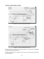
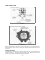
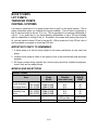
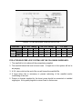
1
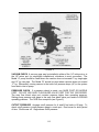
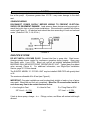
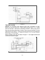
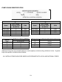
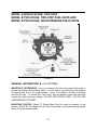
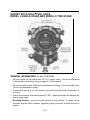
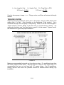
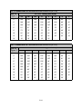
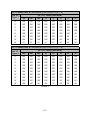
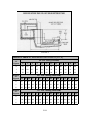
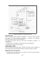
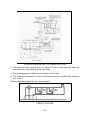
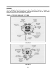
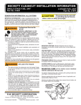
FOR A-7000 SINGLE-STAGE AND B-8000 TWO-STAGE FUEL UNITS MODELS A1 & B1 FOR 1725 RPM, BLACK LABEL MODELS A2 & B2 FOR 3450 RPM, WHITE LABEL FIGURE 1 GENERAL INFORMATION ALL SYSTEMS IMPORTANT INFORMATION Long or oversized inlet lines may require the pump to operate dry during initial bleeding period. In such cases, the priming may be assisted by injecting fuel oil into the pump gearset. Under lift conditions, oil lines and fittings must be air tight. To assure this, “pipe dope” may be applied to both the used and unused inlet and both return fittings. DO NOT USE TEFLON TAPE!! DO NOT USE COMPRESSION FITTINGS!! MOUNTING POSITION Model “A” Single-Stage Fuel Unit may be mounted in any position. Model “B” Two-Stage Fuel Unit may be mounted in any position except upside down (1/8” ports pointed down). II-1 FIGURE 2 VACUUM CHECK A vacuum gage may be installed in either of the 1/4” inlet ports or in the 1/8” return port (on single-pipe installations), whichever is most convenient. The Model “A” pump should be used where the vacuum does not exceed 6” hg. single-pipe and 12” hg. two-pipe. The Model “B” should be used where vacuum does not exceed 17” hg. Remember, running vacuum is the total of all pressure drops (∆P) in the system from tank to inlet of pump. PRESSURE CHECK If a pressure check is made, use GAGE PORT OR NOZZLE PORT. DO NOT USE EASY FLOW BLEED VALVE PORT FOR THE 7000 SERIES. The easy flow bleed valve port contains pressure higher than operating pressure. Setting pump pressure with gage in the easy flow bleed valve port results in WRONG operating pressure. The 7400 is an exception (see Figure 2). CUTOFF PRESSURE Average cutoff pressure for A and B fuel units is 80 psig. To check cutoff pressure, install pressure gage in nozzle port. Run burner for short period of time. Shut burner off. Gage shows cutoff pressure. II-2 CAUTION Pressurized or gravity feed installations must not exceed 10 P.S.I. on inlet line or return line at the pump. A pressure greater than 10 P.S.I. may cause damage to the shaft seal. SOLENOID WIRING DISCONNECT POWER SUPPLY BEFORE WIRING TO PREVENT ELECTICAL SHOCK OR EQUIPMENT DAMAGE. Lead wires on these devices are long enough to reach the juction box on most burner installations. Wire solenoid in parallel with burner motor (see Figure 3). All electical work should be done according to local and national codes. (Solenoid 115V, 0.1A, 60 Hz.) FIGURE 3 ONE-PIPE SYSTEM DO NOT INSTALL BY-PASS PLUG! Connect inlet line to pump inlet. Start burner. Arrange primary burner control for continuous operation during purging. Open easy flow bleed valve 1 turn CCW. Bleed unit until all air bubbles disappear-HURRIED BLEEDING WILL IMPAIR EFFICIENT OPERATION OF UNIT. Tighten easy flow bleed valve securely (Figure 4). For additional information, see Single-Pipe Installation Section, page III-1 of this manual. The SUNTEC MODEL “A”-70 FUEL UNIT may be installed ONE-PIPE with gravity feed or lift. The maximum allowable lift is 8 feet (see Figure 4). IMPORTANT: One-pipe installations must be absolutely airtight or leaks or loss of prime may result. Bleed line and fuel unit completely. Bleed for 15 seconds after last air is seen from easy flow to be certain lines are air free. L = Line Length in Feet H = Head in Feet Q = Firing Rate in GPH 1/2” Line L = 6-.75H .00218Q 3/8” Line L = 6-.75H .0086Q If tank is above pump, change - to +. Fittings, valves, and filters will reduce total length allowed. II-3 FIGURE 4 TWO-PIPE SYSTEM REMOVE 1/16” BY-PASS PLUG FROM PLASTIC BAG ATTACHED TO UNIT. Remove 1/4” plug from return port. Insert by-pass plug (see Figure 1 or 2). Attach return and inlet lines. Start burner-air bleeding is automatic. Opening easy flow air bleed valve will allow a faster bleed, if desired. Return line must terminate 3-4” above supply line inlet (see Figure 5). Failure to do this may introduce air into the system and could result in loss of prime. For additional information, see Two pipe Installation Section, page III-3 of this manual. Always terminate return line as shown in Figure 5. Line lengths include both vertical and horizontal lengths. FIGURE 5 II-4 A. SINGLE-STAGE • TWO-PIPE MAXIMUM LINE LENGTH (H + R) 1725 RPM Lift “H” 3/8” OD 1/2” OD Figure 5 Tubing Tubing 3 GPH 3 GPH 0’ 86’ 100’ 1’ 80’ 100’ 2’ 75’ 100’ 3’ 70’ 100’ 4’ 64’ 100’ 5’ 59’ 100’ 6’ 54’ 100’ 7’ 49’ 100’ 8’ 43’ 100’ 9’ 37’ 100’ 10’ 32’ 100’ 11’ 26’ 100’ 12’ 21’ 85’ 13’ 63’ 14’ 42’ B. TWO-STAGE TWO-PIPE MAXIMUM LINE LENGTH (H + R) 1725 RPM Lift “H” Figure 5 3/8” OD Tubing 1/2” OD Tubing 0’ 2’ 4’ 6’ 8’ 10’ 12’ 14’ 16’ 18’ 3 GPH 100’ 100’ 89’ 80’ 70’ 61’ 51’ 41’ 32’ 22’ 7 GPH 91’ 83’ 75’ 67’ 59’ 51’ 43’ 35’ 27’ - 3 GPH 100’ 100’ 100’ 100’ 100’ 100’ 100’ 100’ 100’ 88’ 7 GPH 100’ 100’ 100’ 100’ 100’ 100’ 100’ 100’ 100’ 74’ II-5 3450 RPM 3/8” OD Tubing 3 GPH 7 GPH 84’ 71’ 78’ 66’ 73’ 62’ 68’ 57’ 63’ 53’ 57’ 48’ 52’ 44’ 47’ 39’ 42’ 35’ 36’ 31’ 31’ 27’ 26’ 22’ 21’ 18’ - 1/2” OD Tubing 3 GPH 7 GPH 100’ 100’ 100’ 100’ 100’ 100’ 100’ 100’ 100’ 100’ 100’ 100’ 100’ 100’ 100’ 100’ 100’ 100’ 100’ 100’ 100’ 100’ 100’ 87’ 83’ 70’ 62’ 52’ 41’ 35’ 3450 RPM 3/8” OD Tubing 3 GPH 7 GPH 93’ 80’ 85’ 73’ 77’ 66’ 69’ 59’ 60’ 52’ 52’ 45’ 44’ 38’ 36’ 31’ 27’ 24’ - 1/2” OD Tubing 3 GPH 7 GPH 100’ 100’ 100’ 100’ 100’ 100’ 100’ 100’ 100’ 100’ 100’ 100’ 100’ 100’ 100’ 100’ 100’ 93’ 76’ 65’ PUMP USAGE IDENTIFICATION A B Model Max. Nozzle Capacity (GPH) At 100 PSI RPM A1V-7100 A2V-7100 A2V-7400 A1Y-7900 A2Y-7900 3 3 3 7 7 1725 3450 3450 1725 3450 Strainer Type V Y T G UL Strainer Rating (GPH)* # 2 Fuel Oil 3 7 16 23 Model Max. Nozzle Capacity (GPH) At 100 PSI RPM B1V-8200 B2V-8200 B1Y-8900 B2Y-8900 3 3 7 7 1725 3450 1725 3450 Designator A B C D Rotation/Nozzle Location RH/RH RH/LH LH/LH LH/RH *Maximum firing rate not to exceed maximum nozzle capacity or strainer rating, whichever is less. A greater firing rate requires a suitable external strainer. ALL INSTALLATIONS SHOULD BE MADE IN ACCORDANCE WITH LOCAL AND NATIONAL CODES. II-6 MODEL A SINGLE-STAGE, TWO-STEP MODEL B TWO-STAGE, TWO-STEP FUEL UNITS AND MODEL B TWO-STAGE, HIGH-PRESSURE FUELS UNITS FIGURE 1 GENERAL INFORMATION ALL SYSTEMS IMPORTANT INFORMATION Long or oversized inlet lines may require the pump to operate dry during initial bleeding period. In such cases, the priming may be assisted by injecting fuel oil into the pump gearset. Under lift conditions, oil lines and fittings must be air tight. To assure this, “pipe dope” may be applied to both the used and unused inlet and both return fittings. DO NOT USE TEFLON TAPE!! DO NOT USE COMPRESSION FITTINGS!! MOUNTING POSITION Model “A” Single-Stage Fuel Unit may be mounted in any position. Model “B” Two-Stage Fuel Unit may be mounted in any position except upside down (1/8” ports pointed down). II-7 FIGURE 2 VACUUM CHECK A vacuum gage may be installed in either of the 1/4” inlet ports or in the 1/8” return port (on single-pipe installations), whichever is most convenient. The Model “A” pump should be used where the vacuum does not exceed 6” hg. single-pipe and 12” hg. two-pipe. The Model “B” should be used where vacuum does not exceed 17” hg. Running vacuum is the total of all pressure drops (∆P) from the tank to the inlet of the pump. CAUTION Pressurized or gravity feed installations must not exceed 10 P.S.I. on inlet line or return line at the pump. A pressure greater than 10 P.S.I. may cause damage to the shaft seal. TWO-STEP-PUMPS FIGURE 2 MODEL SHOWN IS RIGHT-HAND ROTATION; ALL PORTS ARE REVERSED FOR LEFT-HAND ROTATION. SOLENOID WIRING Refer to burner manufacturer’s manual for instructions. II-8 REGULATOR SETTING Install pressure gage in gage port (remove after adjustment); proper nozzle in nozzle line. Low Fire -- With solenoid de-energized, adjust low-fire regulator to desired pressure. (Range 100 to 200 PSI) High Fire -- With solenoid energized, adjust high-fire regulator to desired pressure. (Range 200 to 300 PSI) NOTE: EXTERNAL CUTOFF VALVE IS REQUIRED. ONE-PIPE SYSTEM FIGURE 3 DO NOT INSTALL BY-PASS PLUG! Connect inlet line to pump inlet. Start burner. Arrange primary burner control for continuous operation during purging. Open easy flow bleed valve 1 turn CCW. Bleed unit until all air bubbles disappear -- HURRIED BLEEDING WILL IMPAIR EFFICIENT OPERATION OF UNIT. Tighten easy flow bleed valve securely. For additional information, see Single-Pipe installation Section, page III-1 of this manual. ONE-PIPE SYSTEM MODEL A FIGURE 3 The SUNTEC MODEL “A”-70 FUEL UNIT may be installed ONE-PIPE with gravity feed or lift. The maximum allowable lift is 8 ft. -- see Figure 3. IMPORTANT: One-pipe installations must be absolutely airtight or leaks or loss of prime may result. Bleed line and fuel unit completely. Bleed for 15 seconds after last air is seen from easy-flow to be certain lines are air free. II-9 L = Line Length in Feet H = Head in Feet Q = Firing Rate in GPH 1/2” Line L = 6-.75H .00218 Q 3/8” Line L = 6-.75H .0086 Q If tank is above pump, change - to +. Fittings, valves, and filters will reduce total length allowed. TWO-PIPE SYSTEM FIGURE 4 REMOVE 1/16” BY-PASS PLUG FROM PLASTIC BAG ATTACHED TO UNIT. Remove 1/4” plug from return port. Insert by-pass plug (see Figure 1 or 2), tighten plug. Attach return and inlet lines. Start burner - air bleeding is automatic. Opening easy flow air bleed valve will allow a faster bleed if desired. Return line must terminate 3-4” above supply line inlet (see Figure 4). Failure to do this may introduce air into the system and could result in loss of prime. For additional information, see Two-Pipe Installation Section, page III-3 of this manual. TWO-PIPE SYSTEM MODEL A AND B FIGURE 4 Always terminate return line as shown in Figure 4. Line lengths include both vertical and horizontal lengths. ALL INSTALLATIONS SHOULD BE MADE IN ACCORDANCE WITH LOCAL AND NATIONAL CODES. II-10 MODEL A SINGLE-STAGE TWO-STEP LINE LENGTH (H + R) Lift “H” Figure 4 0’ 1’ 2’ 3’ 4’ 5’ 6’ 7’ 8’ 9’ 10’ 3/8” OD Tubing 10 GPH 16 GPH 33’ 29’ 31’ 27’ 28’ 25’ 25’ 23’ 23’ 20’ 21’ 18’ 18’ 16’ 16’ 14’ 13’ 12’ 11’ 9’ - TWO-PIPE MAXIMUM 3450 RPM 1/2” OD Tubing 10 GPH 16 GPH 100’ 100’ 100’ 100’ 100’ 98’ 100’ 89’ 92’ 80’ 82’ 72’ 72’ 63’ 62’ 55’ 52’ 46’ 43’ 37’ 33’ 29’ 23 GPH 72’ 66’ 59’ 53’ 46’ 40’ 34’ 27’ 20’ 14’ 8’ 5/8” OD Tubing 23 GPH 100’ 100’ 100’ 100’ 100’ 100’ 100’ 88’ 72’ 56’ 39’ MODEL B TWO-STAGE TWO-STEP AND TWO-STAGE TWO-PIPE MAXIMUM LINE LENGTH (H + R) HIGH-PRESSURE 3450 RPM Lift “H” 3/8” OD 1/2” OD 5/8” OD Figure 4 Tubing Tubing Tubing 10 GPH 16 GPH 10 GPH 16 GPH 23 GPH 23 GPH 0’ 70’ 60’ 100’ 100’ 100’ 100’ 2’ 64’ 55’ 100’ 100’ 100’ 100’ 4’ 58’ 50’ 100’ 100’ 100’ 100’ 6’ 52’ 44’ 100’ 100’ 100’ 100’ 8’ 45’ 39’ 100’ 100’ 100’ 100’ 10’ 39’ 34’ 100’ 100’ 100’ 100’ 12’ 33’ 28’ 100’ 100’ 94’ 100’ 14’ 27’ 23’ 100’ 91’ 76’ 100’ 16’ 21’ 18’ 81’ 70’ 59’ 100’ 18’ 57’ 49’ 41’ 100’ * Maximum firing rate not to exceed maximum nozzle capacity or strainer rating, whichever is less. A greater firing rate requires a suitable external strainer. II-11 SUNTEC ROTA-ROLL FUEL UNITS MODEL J SINGLE-STAGE AND MODEL H TWO-STAGE GENERAL INFORMATION ALL SYSTEMS 1. Oil lines should not be smaller than 1/2” O.D. copper tubing. See line sizing charts in this section or check line sizing on page III-7 of this manual. 2. Oil lines must be airtight. Check all connections and fittings. Do not use teflon tape. Do not use compression fittings. 3. During initial start-up or on a dry system, prime the pump with clean lubricating oil or motor oil. 4. Return line pressure must never exceed 10 PSI. Higher pressures can damage the seal or cause leaks. 5. Mounting Position - J pumps can be mounted in any position. H pumps can be mounted with the piston chamber (regulating valve) horizontal at either the top or bottom. II-12 ONE-PIPE SYSTEM Do not install by-pass plug! Connect inlet line to pump inlet. Start burner. Open easy flow bleed valve one turn CCW. Bleed unit until all air bubbles disappear. Tighten easy flow bleed valve. Figures 1 and 2 show typical one-pipe installations. J and H pumps are not recommended for lifts (H) above two feet or 2 inches mercury inlet vacuum with the exception of the J2XXF pump. For additional information, see Single-Pipe Installation Section, page III-1 of this manual. Figures 1 and 2 are typical one-pipe systems. FIGURE 1 FIGURE 2 II-13 L = Line Length in Feet H = Head in Feet Q = Firing Rate in GPH 1/2” Line L = 2-.75H .00218 Q 3/8” Line L = 2-.75H .0086 Q If tank is above pump, change - to +. Fittings, valves, and filters will reduce total length allowed. TWO-PIPE SYSTEM Install by-pass plug inside the return port of the pump, using an allen wrench and making sure it is tight. (See illustration at the beginning of this section.) On a connected two-pipe, the fuel pump is self-priming. Model J can be used two-pipe to 12-inch mercury vacuum; Model H can be used to 17-inch mercury vaccum. For additional information, see Two-Pipe Section, page III-3 of this manual. Figures 3 and 4 are illustrations of typical two-pipe installations. FIGURE 3 Maximum recommended horizontal run for suction or return. For conditions longer than the charts, please contact factory. Although there is a chart for 3/8” copper lines, it is recommended that you not use less less 1/2” copper tubing. On all installations, running vacuum and return line pressure should be checked before leaving any installation. II-14 LIFT CONDITION MAXIMUM LINE LENGTH (H + R) 3/8” O.D. Tubing (1725 RPM) Lift “H” Figure 3 J2 J3 J4 J5 J6 H2 H3 H4 H5 H6 0’ 78’ 78’ 63’ 48’ 37’ 100’ 90’ 75’ 65’ 55’ 2’ 68’ 68’ 55’ 42’ 32’ 100’ 83’ 70’ 60’ 51’ 4’ 58’ 58’ 47’ 36’ 28’ 92’ 76’ 64’ 55’ 47’ 6’ 49’ 49’ 39’ 30’ 23’ 84’ 70’ 58’ 50’ 42’ 8’ 39’ 39’ 32’ 24’ 18’ 76’ 63’ 53’ 45’ 38’ 10’ 29’ 29’ 24’ 18’ 14’ 68’ 56’ 47’ 40’ 34’ 12’ 19’ 19’ 16’ - - 60’ 49’ 41’ 36’ 30’ 14’ - - - - - 52’ 43’ 36’ 31’ 26’ 16’ - - - - - 43’ 36’ 30’ 26’ 22’ 18’ - - - - - 35’ 29’ 24’ 21’ - LIFT CONDITION MAXIMUM LINE LENGTH (H + R) Lift “H” Figure 3 0’ 100’ 100’ 100’ 100’ 100’ 100’ 100’ 100’ 100’ 100’ 100’ 94’ 2’ 100’ 100’ 100’ 100’ 100’ 100’ 100’ 100’ 100’ 100’ 100’ 87’ 4’ 100’ 100’ 100’ 100’ 100’ 100’ 100’ 100’ 100’ 100’ 100’ 80’ 6’ 100’ 100’ 100’ 100’ 91’ 100’ 100’ 100’ 100’ 100’ 100’ 73’ 8’ 100’ 100’ 100’ 95’ 73’ 100’ 100’ 100’ 100’ 100’ 93’ 66’ 10’ 100’ 100’ 94’ 71’ 55’ 100’ 100’ 100’ 100’ 100’ 83’ 59’ 12’ 77’ 77’ 62’ 48’ 36’ 100’ 100’ 100’ 100’ 100’ 73’ 52’ 14’ 39’ 39’ 31’ 24’ 18’ 100’ 100’ 100’ 100’ 100’ 63’ 45’ 16’ - - - - - 100’ 100’ 100’ 100’ 87’ 53’ 38’ 18’ - - - - 70’ 43’ 31’ 1/2” O.D. Tubing (1725 RPM) J2 J3 J4 J5 J6 H2 H3 100’ 100’ FIGURE 3 II-15 H4 97’ H5 83’ H6 H7 H8 (Figure 3 continued on next page) LIFT CONDITION MAXIMUM LINE LENGTH (H + R) 1/2” O.D. Tubing (3450 RPM) Lift “H” Figure 3 JJ2 JA2 JB2 J2 J3 J4 J5 J6 0’ 100’ 100’ 100’ 100’ 100’ 100’ 92’ 71’ 2’ 100’ 100’ 100’ 100’ 100’ 100’ 80’ 62’ 4’ 100’ 100’ 100’ 100’ 100’ 89’ 69’ 53’ 6’ 91’ 91’ 91’ 91’ 91’ 75’ 57’ 44’ 8’ 73’ 73’ 73’ 73’ 73’ 60’ 46’ 35’ 10’ 55’ 55’ 55’ 55’ 55’ 45’ 34’ 27’ 12’ 36’ 36’ 36’ 36’ 36’ 30’ 23’ 18’ 14’ 18’ 18’ 18’ 18’ 18’ - - - LIFT CONDITION MAXIMUM LINE LENGTH (H + R) 1/2” O.D. Tubing (3450 RPM) Lift “H” Figure 3 HH2 HA2 HB2 H2 H3 H4 H5 H6 0’ 100’ 100’ 100’ 100’ 100’ 100’ 98’ 84’ 2’ 100’ 100’ 100’ 100’ 100’ 100’ 90’ 77’ 4’ 100’ 100’ 100’ 100’ 100’ 93’ 81’ 69’ 6’ 100’ 100’ 100’ 100’ 94’ 83’ 72’ 62’ 8’ 100’ 100’ 100’ 96’ 83’ 73’ 64’ 54’ 10’ 100’ 97’ 90’ 83’ 72’ 63’ 55’ 47’ 12’ 89’ 82’ 76’ 70’ 60’ 53’ 46’ 40’ 14’ 72’ 67’ 62’ 57’ 49’ 43’ 38’ 32’ 16’ 56’ 51’ 48’ 44’ 38’ 33’ 29’ 25’ 18’ 39’ 36’ 33’ 26’ 23’ 20’ - 30’ FIGURE 3 II-16 (Figure 3 continued on next page) LIFT CONDITION MAXIMUM LINE LENGTH (H + R) 5/8” O.D. Tubing (3450 RPM) Lift “H” Figure 3 JJ2 JA2 JB2 J2 J3 J4 J5 J6 0’ 100’ 100’ 100’ 100’ 100’ 100’ 100’ 100’ 2’ 100’ 100’ 100’ 100’ 100’ 100’ 100’ 100’ 4’ 100’ 100’ 100’ 100’ 100’ 100’ 100’ 100’ 6’ 100’ 100’ 100’ 100’ 100’ 100’ 100’ 100’ 8’ 100’ 100’ 100’ 100’ 100’ 100’ 100’ 98’ 10’ 100’ 100’ 100’ 100’ 100’ 100’ 96’ 74’ 12’ 100’ 100’ 100’ 100’ 100’ 83’ 64’ 49’ 14’ 51’ 51’ 51’ 51’ 51’ 41’ 32’ 25’ LIFT CONDITION MAXIMUM LINE LENGTH (H + R) 5/8” O.D. Tubing (3450 RPM) Lift “H” Figure 3 HH2 HA2 HB2 H2 H3 H4 H5 H6 0’ 100’ 100’ 100’ 100’ 100’ 100’ 100’ 100’ 2’ 100’ 100’ 100’ 100’ 100’ 100’ 100’ 100’ 4’ 100’ 100’ 100’ 100’ 100’ 100’ 100’ 100’ 6’ 100’ 100’ 100’ 100’ 100’ 100’ 100’ 100’ 8’ 100’ 100’ 100’ 100’ 100’ 100’ 100’ 100’ 10’ 100’ 100’ 100’ 100’ 100’ 100’ 100’ 100’ 12’ 100’ 100’ 100’ 100’ 100’ 100’ 100’ 100’ 14’ 100’ 100’ 100’ 100’ 100’ 100’ 100’ 89’ 16’ 100’ 100’ 100’ 100’ 100’ 92’ 80’ 69’ 18’ 100’ 100’ 92’ 73’ 64’ 56’ 48’ 85’ FIGURE 3 II-17 FIGURE 4 GRAVITY FEED MAXIMUM LINE LENGTH (H + R) Distance “H” Figure 4 J2 J3 J4 J5 J6 H2 H3 H4 H5 H6 H7 H8 0’ 64’ 64’ 53’ 41’ 31’ 75’ 75’ 70’ 60’ 51’ 30’ 20’ 1’ 69’ 69’ 57’ 45’ 34’ 78’ 78’ 72’ 62’ 52’ 31’ 21’ 2’ 74’ 74’ 61’ 48’ 36’ 80’ 80’ 75’ 64’ 54’ 32’ 22’ Distance “H” Figure 4 3/8” O.D. Tubing (1725 RPM) 3/8” O.D. Tubing (3450 RPM) JJ2 JA2 JB2 J2 J3 J4 J5 J6 HH2 HA2 HB2 H2 H3 H4 H5 H6 0’ 31’ 31’ 31’ 31’ 31’ 25’ 19’ 15’ 25’ 25’ 25’ 25’ 25’ 23’ 20’ 17’ 1’ 33’ 33’ 33’ 33’ 33’ 27’ 21’ 16’ 26’ 26’ 26’ 26’ 26’ 25’ 22’ 18’ 2’ 35’ 35’ 35’ 35’ 35’ 29’ 23’ 17’ 27’ 28’ 28’ 28’ 29’ 26’ 23’ 19’ H3 Distance “H” Figure 4 1/2” O.D. Tubing (3450 RPM) JJ2 JA2 JB2 J2 J3 J4 J5 J6 H4 H5 H6 0’ 100’ 100’ 100’ 100’ 100’ 99’ 77’ 59’ 100’ 100’ 100’ 100’ 100’ 94’ 81’ 69’ 1’ 100’ 100’ 100’ 100’ 100’ 100’ 83’ 63’ 100’ 100’ 100’ 100’ 100’ 99’ 85’ 72’ 2’ 100’ 100’ 100’ 100’ 100’ 100’ 89’ 68’ 100’ 100’ 100’ 100’ 100’ 100’ 89’ 76’ II-18 HH2 HA2 HB2 H2 PUMP USAGE IDENTIFICATION • EXAMPLE J3 B A B 100 MOUNTING PRESS. RATING (NO LETTER -- 100 PSI) ROTATION STRAINER TYPE MODEL Strainer Type B P UL Strainer Rating (GPH)* #2 Fuel Oil 7 Unlimited J PUMP Model JA2B JB2B JJ2B J2B J2BF J3B J3B-B J3P-B J4P J5B J5P J6B-B J6B J6B-C J6K H PUMP Max. Nozzle Capacity (GPH) at Rated Pressure 1725 3450 RPM RPM 0 0 0 3 3 7 0 0 10 16 16 15 20 7 20 7 10 3 16 16 20 14 14 30 40 40 50 55 40 55 Rated Pressure (PSI) 100 100 100 100 100 100 200 200 100 100 100 200 100 300 100 Model HA2B HA2P HH2B H2B H2P H3B-B H3B H3B-C H3P H3P-B H3P N-C H4P-C H4P H4P N-C H5P H6B-C H6P H6P-C H6P N-C H7P-B H7P H8P H8P N-C Max. Nozzle Capactiy (GPH) at Rated Pressure 1725 3450 RPM RPM 0 0 0 3 3 0 7 0 7 0 0 0 10 15 16 7 20 7 10 30 40 80 55 7 7 3 16 16 14 20 7 20 14 14 16 30 20 40 40 55 40 45 80 N/A N/A N/A Rated Pressure (PSI) 100 100 100 100 100 200 100 300 100 200 300 300 100 300 100 300 100 300 300 200 100 100 300 * Maximum firing rate not to exceed maximum nozzle capacity or strainer rating, whichever is less. A greater firing rate requires a suitable external strainer. II-19 WASTE OIL PUMPS Waste oil pumps are designed to supply oil up to 1500 centistokes to remote tanks or heaters. Line sizing listed below is calculated for multi-weight oils such as 10W-30W maintained at 32°F minimum, and straight-weight oils such as 40W, 50W, 90W and heavier gear lubes maintained at 50 °F minimum. Pump Model No. J3NBN-A132B A2RA-7736 A2RA-7737 A1RA-7738 RPM Delivery Pressure Flow GPH Maximum Operating Vacuum 1725 1725 3450 1725 3450 1725 20-40 psi 30 psi** 0-100 psi 10-20 psi 10-20 psi 100-150 psi 18 Max. 2.5 GPH 2.5 GPH 2.5 GPH 2.5 GPH 2.5 GPH 20 In. Hg. * * * * * Horsepower < 1000 CST > 1000 CST 1/6 HP 1/8 HP 1/7 HP 1/8 HP 1/7 HP 1/8 HP 1/4 HP 1/8 HP 1/7 HP 1/8 HP 1/7 HP 1/8 HP * 20 In. Hg. for fuels more viscous than #2 fuel oil; 10 In. Hg. for #2 fuel oil and lighter ** Use alternate nozzle port INLET OR SUPPLY LINES Pump Model Number J3NBN-A132B J3NBN-A132B A2RA-7736 (7737, 7738) A2RA-7736 (7737, 7738) Inlet Line Size I.D. 3/4 in. 1 in. 1/2 in. 3/4 in. Inlet Line (L) Maximum 20 ft. 60 ft. 20 ft. 90 ft. Waste oil pumps are designed for one-pipe or single-line installation. Do not install the by-pass plug. Do not use teflon tape. Use J.I.C. flare or pipr fittings only. Do not exceed 10 psi (manufacturer) or 3 psi (NFPA) when supplying to inlet of pumps. It can cause seal damage. FILTERS Waste oil pumps have an internal secondary 30 x 30 mesh strainer. An external primary 50 x 50 mesh strainer is required. This is supplied by the burner/furnace manufacturer. For transfer systems, this must be supplied by installer/user. II-20 TYPICAL TANK INSTALLATIONS FIGURE 1 TYPICAL TANK INSTALLATION FIGURE 2 TYPICAL TANK INSTALLATION Floating pickups are manditory for all waste oil systems. They must be a comparable line size with the rest of the inlet line. In ambient temperatures to oil supply lines are lower than recommended, strip heaters should be installed. II-21 PUMP CONNECTIONS FIGURE 3 FIGURE 4 Install a vacuum gage in the inlet line close to the pump or in an unused inlet port. During operation, vacuum must not exceed the operating vacuum previously listed in this section. PRIMING PROCEDURE It is advisable on initial start-up to prefill the pump with clean, room temperature oil through the inlet port. Start pump and open bleed valve. Bleed pump for several minutes or until air-free oil is observed flowing from bleed port. II-22 BOOST PUMPS LIFT PUMPS TRANSFER PUMPS CENTRAL SYSTEMS It is easier to push fuel oil to a given location than to pull it to the same location. This is easily understood when you consider the forces available. Fuel oil starts to separate or boil at vacuum levels as low as 10 in. hg. This is equivalent to a pressure differential of 4.9 psi. If you push the oil, you have pressure differentials of up to 300 psi available with no separation or boiling of the oil. Simplified, this means that having the pump lift oil, you are limited to about 15 feet of vertical lift. With a pressure of only 100 psi, the oil can be pushed or pumped up more than 200 feet. IMPORTANT POINTS TO REMEMBER: 1. A boost pump is a fuel oil pump subject to the same restrictions as any other fuel pump. 2. Install a boost pump as close to the supply of fuel oil as economically and physically possible. 3. All burner pumps being supplied by a boost pump should be installed single-pipe, even if they are two-stage pumps. MODELS AND SELECTIONS BOOST PUMP Item Complete Boost Pump Assembly: (Including Motor) Boost Pump Assembly Less Motor Pressure Switch BB-1020M BH-1030M BH-1070M BB-1020R BH-1030R BH-1070R Adapter for 48N Motor Includes Pump Model B2VA-8241-5 H3BA-E100B H6BA-E100B B2VA-8241-5 H3BA-E100B H6BA-E100B P/N 128117 P/N 134462 II-23 Pump Rotation (from shaft end) R.H. R.H. R.H. R.H. R.H. R.H. 40 VA & 200 psi Max. Delivery GPH @ RPM 20 30 70 20 30 70 50 psi close Boost pump assemblies are supplied with or without drive motors. The pump has an internal valve regulator (standard 10-20 psi range). The valve regulates pressure and provides a check against loss of head during shut downs. This eliminates the need for an external check valve. Standard assemblies are capable of pushing oil to 35 feet vertical height. For higher applications, a simple spring change can meet your specific requirements. To select the correct boost pump, find the total firing rate of all the burners being supplied and select a GPH rating higher. Example 1: We have four burners with the following nozzle capacities or firing rates: 1 = .8 GPH 2 = .75 GPH 3 = 1.35 GPH 4 = 2.25 GPH Total = 5.15 GPH required Select a BB1020M which will supply 20 GPH. Remember: The firing rates are determined by the nozzle size and pressure of the burner pump. Example 2: We have five burners with the following firing rates: 1 = 1.5 GPH Nozzle @ 150 psi = 1.8 GPH 2 = 3.0 GPH Nozzle @ 300 psi = 5.2 GPH 3 = 12.0 GPH Nozzle @ 100 psi = 12.0 GPH 4 = 5.0 GPH Nozzle @ 125 psi = 5.6 GPH 5 = 1.25 GPH Nozzle @ 100 psi = 1.25 GPH Total = 25.85 GPH Select a BH1030 which will supply 30 GPH. Remember: 1. The boost pump is installed two-pipe with a by-pass plug installed and a return line. 2. The burner pumps are installed single-pipe, no by-pass plug installed and no return line. If a pump is installed two-pipe, its return line will demand its gearset capacity. If you had the smallest pump made, this would be 20 GPH. Installed single-pipe, the pump only demands its firing rate which is determined by the size of the nozzle in the burner. II-24 Example: INSTALLATION INSTRUCTIONS: Note: Install in accordance with the National Board of Fire Underwriters’ requirements, local codes, and ordinances where applicable. INLET OR SUCTION SIDE OF BOOST PUMP: Figure 1 illustrates the installation of the inlet or suction side of the boost pump and its return line. Boost pumps should be installed two-pipe for air removal and self-priming. (Two-pipe requires installation of the by-pass plug for proper operation.) In Figure 1, “H” is the vertical lift from the bottom of the tank to the center line of the boost pump. “R” is the horizontal run or distance in feet from the tank to the boost pump. Table 1 gives limits not to exceed in the installation of the inlet line to the boost pump. PRESSURE OR SUPPLY SIDE: There are two common systems used: the loop system and the pressurized system. Use of an auxiliary tank is a form of the loop system. There are other piping configurations which are not recommended, but are in use, and will be discussed. LOOP SYSTEM: Figure 2 illustrates a single-loop system. It offers the advantage of only needing to keep the mainfold full of oil supplied at a rate greater than the total firing rate of all the burners being supplied by the system. Table 2 lists the maximum horizontal runs not to be exceeded. These are calculated for standard boost pumps with the 10-20 psi spring. For higher boosts or longer runs, call the factory and get prompt help to install your system. II-25 FIGURE 1 LOW PRESSURE SIDE INSTALLATION Line Size Lift B Pump H3 Model H6 1/2” O.D. Tubing 5/8” O.D. Tubing 1/2” Pipe 0-7’ 10’ 15’ 0-7’ 10’ 15’ 0-7’ 10’ 15’ 100’ 100’ 100’ 64’ 49’ 24’ 100’ 100’ 65’ 100’ 100’ 100’ 44’ 34’ 17’ 100’ 95’ 48’ 100’ 90’ 65’ TABLE 1 MAXIMUM INLET LINE LENGTH FOR A TROUBLE-FREE LOOP SYSTEM, USE THE FOLLOWING GUIDELINES: 1. The manifold is to be above all the pumps being supplied. 2. The manifold should be level at worst case. A slight rise in the system will aid in air-purging. 3. A 2-ft. riser or kick at the end of the run will insure the manifold fills. 4. A large return line is necessary to prevent siphoning of the manifold and/or overflowing of the vent. 5. Pumps on burners supplied by the boost pump should be connected or installed single-pipe. No by-pass plug and no return lines on the burners. II-26 FIGURE 2 LOOP SYSTEM INSTALLATION Boost Pump 1/2” Tube 1/2” Pipe 3/4” Pipe B 300’ 500’ 2500’ H3 175’ 300’ 1800’ H6 50’ 100’ 600’ TABLE 2 MAXIMUM HORIZONTAL LINE LENGTH* (10-20 PSI SPRING, FACTORY PRESET AT 10 PSI) * For longer runs, contact the factory 6. Maximum pressure at the inlet port to any of the burner pumps is 10 psi by design. However, N.F.P.A. states that maximum allowed is 3 psi. Use the lowest number per applicable codes. If the pressure is going to be higher than permissible, a pressure reducing and/or a vacuum valve must be installed to reduce inlet pressure to the pump. II-27 FIGURE 3 AUXILIARY TANK INSTALLATION AUXILIARY TANK Figure 3 illustrates a typical auxiliary tank installation. It is a form of the loop system, and subject to the same installation requirements. In addition, local ordinances governing auxiliary tanks should be complied with. The auxiliary tank doesn’t need to be more than a few gallons in capacity. advantages are: It’s 1. Allows loop to be completed in close proximity to the main supply tank. 2. Eliminates line surges and race conditions. PRESSURIZED SYSTEM Figure 4 illustrates a pressurized system. Although it is the least common installation, it can be used where space and distance limitations preclude using the loop system. WHEN INSTALLING THIS SYSTEM: 1. The pressure in the manifold must not exceed 10 psi when the boost pump is running and no burners are firing. II-28 FIGURE 4 PRESSURIZED SYSTEM INSTALLATION 2. The pressure in the manifold must not exceed 10 psi nor less than zero when the boost pump is running and all burners are firing. 3. The burner pumps must have vacuum valves on their inlets. 4. The maximum horizontal run of the manifold line must be matched with selections from Table 2. Other configurations which are not recommended: PSEUDO TWO-PIPE II-29 The intent is to gain the advantages of a two-pipe operation, while not causing the boost pump to supply burner pump gearset demand. Actually, the pump already does this internally without the external plumbing. This system includes unnecessary piping and fittings which are possible sources of problems. PRESSURIZED LOOP The intent is to have a full loop without vent and large manifold return. Problems are: 1. Requires boost pump pressure to be set higher than recommended to prevent oscillations between pump valve and manifold valve. 2. Possible plugging of manifold valve, putting too high pressure in manifold. WIRING INSTRUCTIONS Wiring the system depends upon the operation desired: constant or intermittent. A. CONSTANT OPERATION A voltage switch between the power source and the boost pump motor is used for simple ON/OFF operation. Figure 5 illustrates this circuit. B. INTERMITTENT OPERATION A pressure switch (Suntec part number 128117) is connected in the gage port of each heater’s fuel unit. Figure 6 shows the switch’s installation in the circuit. Operation is simple. Pressure developed by the oil burner fuel unit closes the low-voltage switch connected to the fuel unit. This causes the switch relay to energize the boost pump, which starts and stops automatically with the oil burner. For initial start-up, the switch relay may be held in manually, or a manual ON/OFF switch may be connected across the low-voltage wire leading from the switch relay to the pressure switch. With the manual switch in the ON position, the boost pump runs continuously. START UP 1. Start boost pump manually. 2. Set boost pump pressure in manifold to 10 psi or less at closest burner to the boost pump. II-30 FIGURE 5 WIRING FOR CONSTANT OPERATION FIGURE 6 WIRING FOR INTERMITTENT OPERATION 3. Pressurized system - bleed manifold of all air. 4. All systems - bleed pumps starting with one closest to boost pump and proceeding to the furthest away. 5. System should be ready for normal service. SERVICE 1. Check periodically for water accumulation. 2. Change filter (external) as needed. 3. Check pump strainer. 4. Periodically check for manifold pressure. II-31 PROBLEM SOLUTION Boost pump doesn’t run Boost pump runs, but doesn’t supply oil Check electrical connections and supply; check for discharge and return line blockages. Measure inlet vacuum. If too high, check inlet line, filter and valves. Check to see that by-pass plug is properly installed. Check to see that inlet line has no air leaks. Check capacity of boost pump to see that it exceeds total burner requirements. Check to see that pressure rating of boost pump isn’t exceeded by head requirements. In loop system, check to see if oil is passing through the stand pipe or riser. Check inlet line pressure to burner pumps. Boost pump supplies oil but burners do not fire Burner pump seals leaking II-32