1
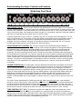
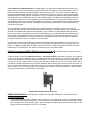
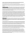
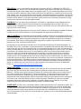
Webb Steel Guitar Amplifier Operating Guide – Owner’s Manual You will learn something new from this Guide, even if you are a long-time user of guitar amplifiers. Beyond the “Quick Start” section, the information presented here is quite detailed, so don’t plan to read everything in one sitting. Take your time and understand each point before proceeding to the next section. All amp owners seek the best sound from their instruments, so thoroughly understand the options available on a Webb for getting it. …Tom Bradshaw QUICK START: Before even turning your Webb amp on or connecting your instrument to it, position the control knobs as listed below. This will enable you to begin using the amplifier immediately and quickly appreciate its outstanding tone. After that, do return here and read the entire manual to fully understand each control and “fine tune” the amp to your desired sound. 1. Rotate the Pickup Sensitivity Control to 10. 1. Turn the Volume control to 2 and the Treble, Midrange and Bass controls to 5. 3. Set the Reverb control to 3. 4. Set the Tone Selector Switch to 2 (middle position). 5. Flip the Equalizer switch to the OUT position. 6. Plug your instrument into the HI input jack. 7. Now turn the Power Switch on; this switch is located on the amp’s back control panel. Note that the Power Switch has three positions, “OFF” (center) and the two “ON” positions. 8. Without any sound created by your instrument, try both “ON” positions of the Power Switch and select the one that provides the least amount of hum, hiss, or noise from the speaker. Fluorescent lighting or the proximity of other electronic appliances typically is the cause of the majority of this noise. NOTE: If you attempt to play immediately after turning the Power Switch on, you may hear a fuzzy sound for the first three seconds of operation. This is normal as the power supply charges to its full capacity. 9. Following completion of the above settings and plugging your guitar into the amp, gradually turn up the Volume to the desired level. NOTE: Do read the caution note in the next section. 10. Adjust the Tone and Reverb controls to your personal preference. You may wish to review the list of settings used by other Webb owners printed at the end of this Guide. You might benefit from the sound preferred by those players before embarking on your own choice of settings. Understanding the Amp’s Controls and Features: Webb Amp Front Panel A&B C D E F G H I J K L M N O INPUT JACKS (A & B): The HI input jack will deliver the greatest amount of volume (gain) for your instrument from the amplifier/speaker(s). That also means the availability of the greatest amount of reserve volume, what musicians call “headroom”. That reserve allows for more sustain by the use of a foot volume pedal. Also when using a foot volume pedal, such headroom provides the option for “punctuating” notes and chords with swells of high volume to create drama and resolution from one chord to another. If a guitar’s signal level is high (i.e. above 1 Volt RMS), using the “HI” input jack could cause distortion. This can occur from guitars with very "hot" pickups or when using effects units that have their own amplification system. If distortion occurs, use the “LO” input jack or try adjusting the Pickup Sensitivity Control explained in the next paragraph. If there is no distortion, using the “HI” input jack at all times is recommended. The “LO” input jack provides approximately half of the volume that the “HI” input jack delivers. PICKUP SENSITIVITY CONTROL (C): This is an innovative control offered by the amp’s designer. It regulates how hard the amplifier is driven by the pickup of the instrument plugged into it. Most guitars allow it to be positioned full ON. Depending on the output voltage from your guitar’s pickup, this is usually appropriate. However, if you experience distortion at particularly high levels of volume, it could mean that your pickup is excessively “hot” and is overdriving the input circuit. Turning this control down and limiting that excessive gain is recommended before choosing the “LO” input jack. Although this control is frequency-compensated (meaning that the low-frequency response is not changed at low volume levels), the amplifier’s volume is decreased when this control is turned down. It is important to note that the Lows and Highs are changed about half as much as in the midrange. This hybrid circuit was designed to compensate for small room acoustics, such as in recording studios, motel rooms, etc. This compensation only happens at reduced volume, not at high volume where it would be unnecessary. VOLUME CONTROL (D): For a steel guitar, volume is affected by the harshness of pick attack, the use of the foot volume pedal, and the Pickup Sensitivity and Volume Controls on the amp. As volume is increased with any amp, the output limits that an amp and its speaker were designed to provide can be challenged. The result of challenging those limits is amp/speaker distortion. And at high volume, even momentary signal peaks from harsh picking or volume pedal swells can drive any amp into audible distortion. Assuming that the speaker used with a Webb amp is manufactured to accommodate the power of a Webb amp, distortion is a rare occurrence. The wattage output is as follows: 180 watts RMS of power with an 8-ohm speaker, 225 watts RMS with a 4-ohm speaker, or 260 watts RMS with a 2-ohm speaker. If distortion does occur, there are built-in options to correct this problem. The volume control (potentiometer) in Webb amps built after 2006 is the audio-taper type. It was selected to provide an “honest” output volume, in that it provides a progressive increase in volume. On previous Webb amps and many other amp brands built today and in the past, linear-taper type potentiometers are used. Such “pots” provide about 90% of full volume at the “3” position on their control knobs. This gives the user the impression that the volume will continue to increase at the same rate if the control knob were turned “on” more. Not true! TONE CONTROLS (E, F & G): The three tone controls on the Webb are of the active design-type; “active” means that an independent amplification circuit powers them. Notice that when you reduce or increase their settings, there is minimal change to the output volume. Other amps, particularly tube amps, will have a noticeable increase or drop in overall volume when these controls are turned up or down. Webb engineering has provided controls to prevent this volume change, a remarkable accomplishment. 3 True Instrument Tone Determination: As a starting point, you might want to determine the true tone of your rd guitar. To do so, turn all 3 tone controls to 5, while making sure the 3-position Tone Selector switch is in the 3 position and the EQ section is turned OFF before playing your instrument. The tone you will hear is what your instrument provides without amplifier coloration. If this proves to be the tone you prefer, the maker of the guitar achieved his goal: providing the tone you like best. Thus, your quest for the “perfect sound” has been realized. The initial tone may be adequate but you may want something better. The Webb amp is designed to make any and all guitars sound good, but more preferably, provide a much better sound. If your pickup “doesn’t have it”, your Webb amp will help your guitar with its limitations. Therefore, it is recommended that you spend some time experimenting with the amp’s controlsparticularly with the 3-position tone switchto find the best sound you can get from your guitar. As you experiment, write down the settings that you initially selected as providing a “good” sound. You will discover that different sized rooms will likely require different settings. Tone preferences are very subjective and personal. The limitations to a good sound are typically 1) your instrument, 2) the negative impact your effects have on your sound, 3) the playing environment, 4) the positioning of your amplifier, and 5) the influence of the opinions and recommendations of other musicians who accompany you. Most musicians will tell you that your tone needs to be adjusted to suit “their” ears. Obviously, your Webb amp does not have control over all of the influences mentioned, but all are important for you to consider! It is likely that your tone controls will end up with blended settings, rather than just being turned up or down. For example, even if you set your highs (treble) correctly, you may discover that the "body" of your guitar’s tone is a bit thin. Try adding some Midrange, then Bass, rather than turning the Treble control down. Experiment to reach the blending of your preference. The options are nearly infinite on your Webb amplifier. REVERB and optional REMOTE REVERB control accessory (H): The Reverb knob controls the amount of signal from the spring reverb unit that is added to the mix. A Remote Reverb Control (an optional accessory - See Figure 2 Below) duplicates the function of the Reverb control. It plugs into the rear panel, and is typically clipped to the right rear leg of your steel guitar where it is conveniently available for making occasional adjustments. If you use a distortion effect with your steel guitar, you may wish to use the reverb remote control for quick and easy changes in the level of the reverb effect. This is occasionally needed to emphasize the fuzz effect needed for also mimicking the sound of the violin and cello. For fuzz or overdrive/rock effects, you might need to set it to a wide range of positions, depending on what effect you want to create. Thus, the closer proximity of a Remote Reverb Control to the player, allows for quickly adapt to any playing mode that the musical selection might dictate. Optional Remote Reverb Unit Accessory REMOTE REVERB JACK: This output jack is located on the amplifier’s back panel. It has three functions. Functions and Benefits: 1. First, and as explained above, it allows for the connection of a remote reverb control (an optional accessory utilizing a 50K audio taper potentiometer). This remote control can regulate the amount of reverb that is mixed with a musical instrument’s primary signal. When utilizing this remote control, the user should first turn the reverb control on the amplifier to it’s full “on” (10) setting. 4 2. Second, it allows for the connection of a remote on/off switch, typically in the form of a “foot switch”. In certain applications, the user might wish to eliminate the reverb effect entirely. Such a remote on/off-type switching unit will accomplish this. 3. Third, it allows for the remote amplification and projection of the reverb signal of the primary amp. To explain: If a cable with _” audio plug is plugged into this jack, then connected to the input of another amplifier, the user can transmit just the reverb response signal of the Webb amp to that separate amplifier. If not at an extreme distance, the resulting sound can be adjusted (on the second amp) to mimic a stereo effect, with a “roomfilling sound”. Musicians are encouraged to experiment with this application and hear how this effect expands the pleasantness of his instrument’s overall sound. An additional benefit of this output jack is when recording (either using a mixing board for home recording, or in a recording studio. The recording engineer can have complete control over the reverb effect. Here’s how: The instrument’s primary signal can be routed to one input of a mixing board, while the reverb effect can be routed to a second input of the mixing board. The recording engineer is then able (at the outset or after the primary recording effort), to mix the primary sound (from the instrument) with the reverb effect generated from the Remote Reverb Output jack. Note: All connections should utilize a low noise (shielded) cable. TONE SELECTOR SWITCH (I): There is a mystical quality that goes beyond simple "tone". It is the sound you hear in your mind and spend excessive time adjusting your amp in an effort to capture. Think of the 3 positions of the Tone Selector Switch as providing you with 3 different amplifiers. The Tone Selector Switch actually provides the benefits of 3 different amplifier voicings, but through a single amp. The original intent behind a voicing switch was to duplicate the sounds of the vintage tube amp, the hybrid amp (part tube/part solid-state) and solid-state amp. The outcome doesn't truly provide this, unless you just happened to own one of each of these amps and conclude the output sound of each position on the Webb matches those amps that you now own or once owned. That isn’t likely, but some owners have professed this opinion. For example, many amp users point to the middle switch position of a Webb amp as matching the tone of the 1964 Fender Twin Reverb, a popular tube amp. Comparisons aside, these "voicing" presets provide three dramatically different foundations for sculpting your tone. Position 1: This position gives plenty of upper mids and highs, but has a strong dip in the low-mids. For lead and steel guitarists, this is the least-used setting. The unique low-mid cut of this particular voicing is most useful for instruments such as fiddle, mandolin, acoustic guitar, or other acoustic instruments that sometimes suffer from low-midrange feedback issues or cloudiness. The low-mid cut can help avoid feedback and also add clarity to certain instruments. On steel guitar or electric guitar, this setting can have a harsh quality, so one should experiment. Adjusting the tone controls and utilizing the EQ component diminishes this harshness, but users rarely do this, leaving this position as the least-used, but being the preferred voice-setting for the other instruments mentioned. Position 2: This setting immediately prompts a user to recognize Webb's celebrated sound, with its clean highs, its "beautifully extended", if not massive, low end, with its full-bodied response. It is the most popular setting used by steel and lead guitarists. It provides tone reminiscent of some of the classic tube amps, with its big, extended bass capacity, strong midrange dip, and clear treble. This voicing tends to match best with current steel guitar pickups. Its big, robust, clear tone will sound great at any volume. But, it can still be adjusted to your personal taste with any of the other options still available in the Webb. Position 3: This position is the only "flat" setting available on the Webb amp. Since there is no voicing or midrange dipping here, the mids sound relatively strong and forward. A few famous steel guitarists, who sought a “gutsy” and “up front” midrange-heavy tone, have preferred this setting. It mimics some classic '50s amplifiers that also had no midrange dip. And guitarists, who utilize a number of effects in their circuit path, find this position appealing. EQUALIZER (EQ) (J, K, L, M, & N): The EQ is likely the most misunderstood “enhancement section” on all guitar amplifiers. It is intimidating to many players, but try to understand it since it allows you to vastly improve the 5 tonal qualities of your guitar’s amplified sound, permitting you to sculpt your tone and likely lead you to that elusive “perfect” sound previously referenced and discussed. The equalizer section electronically splits the tone spectrum into five separate bands. With all the EQ controls in their zero (0) position, there is no equalization. If turned toward the plus (+) side, that frequency band is boosted; turning the knobs toward the minus (-) side diminishes that frequency band. All sections of the EQ circuitry are active, which means that each frequency control has its own amplification system. Thus, each frequency band can be increased or cut, relative to its pre-EQ level. There is a “stacking” relationship between the preamp and EQ sections. From there, you can direct it to the EQ section where it can be further modified into your ultimate sound. Any shaping you do in the preamp section (where the treble, midrange and bass controls are), changes the frequencies that the EQ section controls. The Webb has the capability to, in effect, “EQ” its own “EQ”. This feature is unique to the Webb amp and is helpful in your effort to get outstanding tone. So, you might want to experiment as follows: First, flip the EQ switch to “Out” and position all its control knobs on zero. Turn the amp’s three tone controls (bass, mid and treble) to their mid-positions (five on their scales). Then flip the EQ switch to “In”. Proceed to experiment with each of the five control knobs present in the EQ section. Either boost (+) or limit (-) the sound spectrum controlled by each band until you obtain the sound most pleasing to you from your instrument. The human ear can hear frequencies between 20Hz (Hz = Hertz) and 20,000Hz; 20Hz is the extreme low end and 20,000Hz is the extreme high end of the audio spectrum. In modern guitar amplifiers, the typical and desirable frequencies are usually between 50Hz to 5,000Hz. A 15” speaker was selected to make the important and desirable frequencies sound the way they are preferred to be heard, as Webb believed it would project your instrument's sound the best. We all know that “good” sound is subjective and what may sound good to you, may not be so appreciated by anyone else. But then, you are the one Webb is trying to satisfy first, and this amp has been designed to give you the control options to achieve that satisfaction. The EQ controls are positioned from left to right and affect the sound spectrum as indicated: 1st Control: 50Hz – 150Hz (Bass) 2nd Control: 150Hz – 350Hz (Upper Bass, Lower Midrange) 3rd Control: 350Hz – 650Hz (Mid Range) 4th Control: 650Hz – 1350Hz (Upper Midrange, Lower Treble) 5th Control: 1350Hz – 2500Hz (Treble) How to operate these controls: 1. First, place all the equalizer controls in the “0” (zero) position. Flip the EQUALIZER switch (See amp’s faceplate Figure above) to the "IN" position. 2. Strum your guitar's strings and then decide which string(s) you would prefer to modify. For instance, if the bass strings are too muddy, turn down (-) the first Control (50Hz — 150Hz). But if the bass seems too thin, you may want to turn up (+) that control. Then experiment with the next control. 3. Repeat this procedure for all the strings, using the numbered controls that correspond to each string's frequency range. There will obviously be some overlapping, but you get the idea. As you strum across the strings and adjust the equalizer’s control knobs, you will discover that the control that changes the bass has very little affect on the treble strings, and vice versa. The small amount of overlapping of each EQ control, prevents dead spots. You may also use these controls to "tune your amp” to the room in which you are playing, as different rooms will absorb or boost different frequencies. Furthermore, you can use these controls to help your instrument stand out in a mix. With lots of instruments on stage, your guitar can get lost in the mix as it competes with other instruments that produce similar frequencies. Dialing in your amp's tonal output will result in your guitar being heard, particularly if you choose to create a unique tone or "voice" that you sculpted with your EQ settings. Keep in mind that you don't just have an EQ section to manipulate your sound, you also have the 3-knob tone modification section (Bass, Midrange & Treble controls), and the 3-position Tone Selector Switch. A change to any one of these will have a major effect on the next, making the Webb Steel Guitar Amplifier one of the most tonally versatile amplifiers ever made. [Pardon the bragging here, but we can get excited when 6 recognizing the options available on the Webb!] If you do not need the EQUALIZER to modify/build your primary tone, you may choose to use it as a pre-set option for another desired tone. Switch it "IN" or "OUT" as needed for the option of a desired pre-set tone. For example, since you can make a major tone change with its EQ tone spectrum bands, you may wish to have it preset to obtain the fat-heavy chord-sound of the great Curly Chalker. Or, if you want a cutting, crisp sound similar to steel guitar legend Ralph Mooney, that too can be dialed in. Once it is pre-set, that sound becomes available when you choose to flip the "IN" switch! You just need to take a little time and learn how you want to use the EQUALIZER, a very useful and versatile tone-shaping tool. SPEAKER: All manufacturers select a speaker designed to match the wattage output of the amp they accompany. Those speaker’s voice coils must be capable of handling the high temperatures created by momentary output voltage surges. However, few speakers can take high volume for long periods of timea situation that would lead to premature speaker blow-out/burn-out, even when the volume control is set at half (or less) of its total range. Webb recommends an 8-ohm speaker be employed with its amps. A 4-ohm speaker (or speaker system) can also be used, but users should be aware that speakers with resistances of less than 8 ohms are more prone to destruct because of the high (225) wattage output power provided by Webb’s power design. A speaker or speaker system having less than 8 ohms of resistance does offer a bit more volume during general use. All Webb amplifiers produced after 2006 were equipped with an 8-ohm, 15", Kappalite speaker, manufactured by the Eminence Company. This speaker was found to mimic the response of the JBL speakers previously supplied with Webb amps. [JBL ceased manufacturing amplifier speakers in about 2004.] The Kappalite speaker weighs 8 pounds; a weight appreciated when compared to a usual alnico-magnet amp speaker weighing over 20 pounds. This speaker is front-loaded onto the amp’s ported metal baffle. These speakers use a neodymium magnet in place of an alnico or ceramic magnet. A magnet made of neodymium material is the strongest permanent magnet. [For information regarding these magnets, see http://www.britannica.com/Ebchecked/topic/408837neodymium.] SPEAKER CHAMBER: This innovative chamber, with its front and rear ports, isolates the speaker from the amp chassis. The chamber is riveted and also bonded to the amp’s metal speaker baffle, which is securely mounted to the cabinet’s sidewalls. The chamber has four, front-accessible ports bordering the speaker on the baffle, as well as a 4" X 13" rear-accessible port. Six screws release the speaker grill for access to the baffle. If one, some, or all of these ports are closed, the amp’s sound is altered incrementally. For example, covering the rear port of the chamber, while opening any or all of the front ports, will project the speaker’s back-sounds forward. This provides the ultimate in directional sound, gives additional volume and fullness to the output, and prevents the escape and echoing of the amp's sound out the back, which is typical of open-back speaker cabinets. The amp is delivered with the rear port and the two top front ports covered. The two front-bottom ports have port tubes in place and are otherwise open. This configuration significantly provides a greater bass presence to the sound. If the user chooses to open the top two front ports, the bass presence is somewhat reduced. When the back port is opened, the very common “room-filling” sound of open-back speaker cabinets is created. Port Covers: Four, full-fitting port covers are supplied with each Webb amp, allowing the user to customize the way the speaker projects its sound. Installing certain covers provides options for "personalizing" the tonal characteristics of the amp's sound delivery chamber. Users are encouraged to experiment with the front ports to determine the character of the sound delivered by the chamber. This could mean closing or keeping open one or both of the upper two and/or closing or opening one or both of the bottom two ports. If all 5 ports are closed, the result is the characteristic sound of an enclosed speaker cabinet. By opening the back port (whether any or all of the front ports are opened or closed), the characteristic “room-filling” sound of most "open-back" amplifiers is projected. The options of an adjustably ported and bottom "tubed" speaker chamber is Webb’s effort to support users’ desire to obtain tonal "supremacy", an advantage which discriminating musicians seek but rarely find in most amplification systems. Port Tubes: The amp comes with acoustically designed tubes installed in the lower front ports. Testing revealed little beneficial tonal change if the upper ports have similar tubes. The use of the tubes will emphasize the bass overtones from the amp's speaker, regardless of what speaker is used. All users are encouraged to experiment with these tubes as well as the port covers provided, either having both tubes inserted or just one (and with, 7 perhaps, one other lower port covered). Covering or opening each or all of the 5 available ports will result in different tonal responses. When experimenting, remember to always keep all port covers securely in place, because anything that can vibrate on any amp will, when sound is projected through it! When experimenting with the ports, it is beneficial to have assistance from another person. Their input is helpful in concluding what your “best” sound proves to be; this topic will be discussed again later in this Guide. When evaluating your sound, your assistant in these tests may wish to stand about 20 feet in front of the amp in a fairly large room. USING EFFECTS UNITS: If possible, all effects (commonly referred to as “stomp boxes”), whether fuzz tones, distortion pedals, phase shifters, echo chambers, etc., should be connected between your guitar and your foot volume pedal. These units always create some extraneous and undesirable noise/hiss. By placing them before the volume pedal, the additional noise they emit will be masked, because the signal from your guitar is much louder than the circuit noise these units create. When you back off your volume between voicings, that noise will be reduced along with the guitar signal. If those devices are plugged in after the volume pedal, the noise will stay at the same volume while the guitar volume decreases. Some effects units alter your guitar's tone, usually cutting its highs. This can occur when they are turned off. That is because their switches do not completely remove the effects circuitry from the audio signal port. If an effects unit accomplished this, it is called “true bypass” and usually emphasized in the descriptive information provided with such units. Without true bypass this impacts your sound negatively. Experiment with different brands of these effects units before purchasing, then select the ones that provide you with the sound you want, but has the least amount of circuitry noise or tone change from your guitar when they are turned off. If the effects unit you like does have an unwanted tone change when switched off, you will have to modify its on/off switch to remove all of its circuitry from the line. If that option is not available, you will have to plug it in and unplug it each time you use it. But do remember to avoid plugging and unplugging an effects device unless your volume pedal has been swung to the fully “OFF” position! And, avoid plugging in or unplugging your volume pedal unless the amp’s volume is off! The voltage "pop" that this creates may cause a power spike that can destroy the speaker on ANY amp, regardless of the brand. EFFECTS LOOP: The Webb amp has an integrated “post-EQ” effects loop like most other modern amplifiers. It is important to understand that all effects devices in this loop ARE subject to both the preamp and the EQ's toneshaping capabilities. To the degree that you modify the tone at the amp, you modify the signal to the Effects Loop, for better or worse. You’ll need to experiment to see whatever effect sounds better when fed directly from your guitar or from the Effects Loop. Your volume pedal can also be used in the effects loop. To do this, plug your guitar directly into the front panel of the Webb. Using a patch cord, connect the input jack on your volume pedal to the "Send" jack on the amp's rear panel. Using another patch cord, connect the output on your foot volume pedal's jack to the "Return" jack on the Webb's rear panel. This may reduce electronic noise in some circumstances by reducing the number and length of cords ahead of the amp input, which sometimes act as antenna for unwanted electronic signals. Users of lightbeam volume pedals often find that placing their pedal in the Effects Loop maintains their "highs". To use the effects loop for other devices, you may wish to plug your guitar into the Webb amp in the usual fashion. For your effects units (or a string of such units), use a patch cord and connect that unit into the “Send” jack on the back panel. Then plug that patch cable into the input jack on your effects unit. If you have more than one device, string them in the order of input to output, eventually ending with a patch cord from the last effects device in the string to the “Return” jack on the Webb’s back panel. Make all the pre-set adjustments to each of the effects devices, so that when you “stomp” them on, the desired effect will be achieved. Many players prefer to place Overdrive/Distortion/Fuzz effects between their guitar and foot volume pedal, because these effects generally don’t sound their best with enhanced harmonics. However, most players do prefer to use effects such as chorus, delay, echo or digital reverb primarily through their Effects Loop. A “richer” sound is often realized with this connection format. As always, experiment with the order or chain arrangement series. Remember: to maximize the signal-to-noise ratio, volume pedals should be last in the line/order. An exception is made when variable distortion (increasing with volume) is desired, in which case the distortion device will go after the pedal. So, there are no firm rules, allow your ear to be the judge. And, keep those patch cables as short as possible for fidelity and to minimize hum. 8 RECORDING: You can record directly from the amp by using the LINE OUT or PREAMP OUT (EFFECTS SEND). Both outputs are line level. The PREAMP OUT takes the signal ahead of the power amp. The LINE OUT is a power amp signal, a lower voltage version of the speaker signal. You can connect either output to the input of your recording device. Always try to plug into the "LINE IN" jack and start with your recorder volume control in the “OFF” position. Then, turn the volume control up very slowly until the desired input level is reached. This will avoid possible damage to the input stage of the recorder and help you achieve a desirable recording level with plenty of headroom and no distortion. If you hear an electrical humming sound on your recordings, the problem is usually solved if all the units have their electrical polarity aligned. PLAYBACK: You may want to play an MP3 player, a CD player or a tape player through a Webb amp when playing along with rhythm tracks or instructional materials. It can be plugged into the LO INPUT jack if your playback device is equipped with a volume control. Connect a cord from the "Line Out" of the recorder to the "LO" input jack on the front of the amp. Caution: Start with the playback unit’s volume in the “OFF” position or you may damage the amplifier or speaker! Increase the volume until the desired mix is achieved between the guitar and the MP3/CD player. AMP PLACEMENT: Do not disregard your amp’s position in relation to where you sit. Its positioning will have a major impact on the tone you hear, as well as what your audience hears. Typically, an amp sitting on the floor will have increased bass response, whereas an amp that is on a stand or tilted back will project any of a number of tone variations. Other factors, including stage height, stage volume, a player’s need to hear his sound, whether the amp is mic’d, etc., will affect the output sound. Knowing that your amp will likely sound best to you if it is elevated and tilted back, the preferred elevation is an amp stand. But, a chair, a small table, or other sturdy elevation is acceptable. Most musicians have one ear that is more efficient than the other one. Experiment! After you have determined which is your "best" ear, place the amp behind you and to that side. This is the way to hear your tone and to best determine if you are in tune. Let nothing come between your speaker and your ear. You know what this means if you have ever had someone stand in front of your amp. Your sound gets muffled and your tone changes. If you have to play with your amp directly behind you, make certain it is far enough away that your body doesn’t interfere with the sound you want your audience to hear. Also remember that what you hear is not always what your audience hears. It is best to rely on a friend with a good ear to tell you what sounds best in the audience. Don’t convince yourself that “my best sound is what I hear with MY ear”. Sometimes you have to choose between what is the best sound for your audience and the best sound that you hear. Remember that you are an entertainer and indirectly the audience pays your wages. So, shouldn’t they get your best sound? A good discussion of this subject is found on the Steel Guitar Forum at: http://bb.steelguitarforum.com/viewtopic.php?t=102563 USING TWO AMPS: Method 1 – independent amp settings: Connect a patch cable from the "LO" input jack on the front of the Webb amp to the input jack on the other amp. Changing the control settings on either amp will not affect the other. Method 2 – one amp controls volume and tone for both amps: Connect a patch cable from the “Preamp Out" of the "master" amplifier to the "Effects Return" of the second amplifier. The amps should sound the same; the preamp of the second amp is bypassed. Align the AC electrical polarity of both amps to prevent hum. Also remember that when using two speaker systems, the speakers should be in phase with each other, meaning their cones must move in the same direction for all the sounds they project. Otherwise, you’ll get very noticeable cancellation effects and reduced volume, especially in the lower frequency range. However, as you might suspect, there are some players who appreciate the resultant out-of-phase sound! SLAVE UNITS: A slave unit is a cabinet that contains a speaker powered with its own amplification system, and ideally, should have its own volume control. Using an amp and a slave unit gives you much more output power, and both units are still capable of driving their own extension speakers if you need them to do so. Because both outputs are identical, a slave unit can be driven by using the LINE OUT or PREAMP OUT jacks on the Webb amp. This setup gives you the power of two amps at lower cost, because you do not have two separate preamps in both amplifiers. 9 EXTENSION SPEAKERS: Using an extension speaker in conjunction with the speaker in your Webb amp permits you to play at louder volume settings before speaker-overdrive (distortion) would be experienced. That is because 2 speakers are sharing the volume output load. [Re-read the section on the Volume Control for clarification. Also heed the advice regarding phase alignment previously explained.] An extension speaker may be plugged into either speaker output jack. When using an extension speaker, always be sure to use a true speaker cable (the common type of electrical cord). SPEAKER JACKS: These jacks provide audio output power to your primary speaker and to an extension speaker system, if you employ extra speakers. Both jacks are always operational, so either can be used. Your Webb amp will accept a load impedance of from 2 to 32 ohms with satisfactory results. While the power amp includes a protection circuit that is capable of handling momentary shorting of the speaker leads (but may still blow an output fuse), it is a good practice to keep extension speaker leads separated and not touching each other. Warning: Do not attempt to record out of the speaker jacks, nor connect another amplifier or Slave unit to the speaker jacks. Extreme electrical damage can occur to those units if you attempt to operate from these jacks! Remember to review the section on fuses to understand how the Output Fuse works to protect your Webb amp. POWER CORD: This is a three-wire grounding cord. No attempt should be made to defeat the purpose of the ground lug (round terminal) on this cord; it is a safety feature designed to prevent shocking, which could keep you alive! POWER SWITCH: This 3-position, center-off switch was discussed earlier. It functions as a reverse polarity switch. Under certain conditions, flipping the switch to either "ON" position may decrease input line noise. To eliminate AC hum, it is sometimes necessary to have matching polarity in every device being used at your location. Unfortunately, that isn’t always possible, and you may have to settle for the least amount of hum you can get. AC ACCESSORY OUTLET: The ideal use for this outlet is for powering your effects and recording devices. It ensures proper electrical polarity and grounding for minimizing AC hum. Use the shortest cables and power cords to reduce hum, hiss and other line noises. It is not meant for a coffeepot, or other power-hungry appliances, including another amplifier! Drawing excessive power from this receptacle will lower the line voltage and diminish the power available to your Webb amp. FUSES: These little puppies can save you a lot of money if you respect their purpose. They are there to warn you that something is wrong with either the amp circuit or with the power coming from the wall receptacle. Sometimes a fuse will blow for no apparent reason, but mostly they blow for good reason. Replacing them promptly will often result in the amp operating with no further malfunction. For example, a short in the speaker cable can cause the Output Fuse to blow. If this happens, carefully check your speaker cables for a loose connection or a short (typically an abrasion to a section of the cable). Then correct the problem and install a new fuse. If fuses continue to blow and there is no short in the speaker cable, your amp will require servicing by a competent technician. The Main Fuse protects against a power surge or an electronic failure inside the amp. It is wise to use a surge protector strip to provide AC power to your amp. If you replace the fuse and it blows again, you likely have an electrical failure inside of the amp and it will need to be professionally serviced. The power amplifier section of your Webb amp has an inherent open-circuit protection design, plus current limiting. Should one of Webb amp’s “fast-blow” fuses blow, do not replace it with a fuse of higher CURRENT RATING, or a slow-blow fuse. And, don’t do something really stupid and dangerous such as wrapping the fuse in metal foil to disarm it! Using a fuse other than the exact type and CURRENT RATING listed on the fuse holder may cause extensive damage to the amp and will void your warranty! Once again, if a replacement fuse doesn’t cure the problem and you must complete a playing engagement, use another amp (or even use a P.A. system). Afterwards, contact a technician or the factory for service information. Always keep extra fuses on hand for these rare emergencies, such as power surges. The Webb designers used a common type of fuse so a Webb amp owner could easily find them at gas stations, supermarkets, hardware stores, automotive parts stores or even 24hour convenience stores. 10 OWNER REGISTRATION & TECHNICAL ASSISTANCE: All Webb amp owners are encouraged to register with the manufacturer so they can be notified of any news or important information relating to their amp. By simply emailing your name and address to us, you will get regular notification of any updates and upgrades to your amp. A technician’s service manual is currently available for purchase. It includes schematics, layout diagrams, upgraded component listings, a parts list and a source locator for those parts. If specific technical information is needed beyond the technician’s service manual, contact us at the address below. Amp specifications are subject to change, as Webb constantly strives for more improved and durable components. Electronics technology is a fast-changing industry, with innovations occurring constantly. Webb wishes to notify all interested persons of such changes. CARE AND CLEANING: DO NOT use cleaning solvents on the vinyl exterior. To clean the vinyl wrap, use a brush and warm soap and water, then wipe dry with a clean cloth. After cleaning, the vinyl covering can be “refreshed” by the use of ArmorAll or similar products. CAUTIONS! • There are no user-serviceable parts inside the amp chassis. • Touching certain component parts inside the chassis can lead to severe electrical shock and even death. So, always refer repairs to qualified service personnel. • Heed the warning provided in the section on fuses. • Do not expose the amp to rain or any other moisture. • A Webb amp can create enough volume to damage most eardrums, so avoid positioning yourself directly in front of the speaker. SOME FINAL THOUGHTS: Your Webb amplifier will provide you with many years of enjoyment, while its tonal characteristics and options were designed to provide you with musical inspiration as well as great tone. This Operating Guide is a valuable resource. Keep it handy, as the information will answer most of your questions. As you have surely recognized, it goes beyond simply explaining how the amplifier works. ACKNOWLEDGEMENTS: The preparation of this Operating Guide/Owner’s Manual was through the collaborative efforts of the following friends and technicians: John Campbell, Mark Dayton, George Moore, Brad Sarno, John Bresler, Anthony Marchelli, Obeid Khan, Gary Chiappetta and a little input from me, …Tom Bradshaw CONTACT: Webb Steel Guitar Amplifiers are available from: Pedal Steel Guitar Products P. O. Box 931 - Concord, CA 94522 [email protected] Web site: www.songwriter.com/bradshaw/ Notable Users and their Webb Amp Settings: Tommy White Pickup Sensitivity: 10 Volume: 5 Treble: 0 Mid-Range: 3 Bass: 8 Reverb: 4 1/2 Tone Selector Switch: Center EQ: On Bump the low EQ to +1 Place the center 3 EQ knobs at 0 Set the High EQ knob at –1 Herb Steiner “I own two Webbs currently: a model 614-GP and a 6-14E Steel Guitar Amp, both with JBL E-130 4-ohm speakers. I run the settings on both amps generally the same (given the acoustics of room and stage), and almost never use the EQ on the 614-E Steel Guitar Amp.” 11 Volume: Variable as needed Treble: 1.5 to 2.5 Midrange: 4 to 5 Bass: 8.5 to 9.5 Tone Selector Switch: Center Reverb as needed, usually 3.5, or, if using effects, 0 EQ: Off Bobbe Seymour “I use many different settings as the situation demands. Jazz and Country require different settings, as well as settings for the several different guitars I use. With a Webb, a player can probably get any variation in tone wanted. I’ve found that it gives me an unlimited amount of treble and bass choices. This is very important, as any pro-fissional player can tell you. In this respect, I feel the Webb amp is the very best, giving any user the full choices of tones, giving the player total control over what he/she prefers.” Bruce Bouton Pickup Sensitivity: 10 Volume: As needed Treble: 3 Mid-Range: 4 Bass: 8 Tone Selector Switch: Center EQ: “I rarely used the EQ.” Bass: 9 _ Reverb: 5 EQ Switch: In Low: + _ Next Knob: 0 Next Knob: +1 Next Knob: 2 _ High: 2 _ Jimmy Day Pickup Sensitivity: 2 _ Volume: 1 _ to 3 _ Treble: 2 to 3 _ Midrange: 2 _ 1 Webb Amplifier [WEBB 6-14E “Steel Guitar Amp”] Technician’s Guide and Test Procedures Manufacturing Variations First Amp Series: • • • • • • • • • • • • • • • • • • The first series of Steel Guitar amps was built from 1975 to 1981. The chassis was a twopiece unit with the faceplate mounted to the cabinet from the front. This model had no effects loop and only one fuse. The first 15 amps produced had no serial numbers. The first serial number used began with no. 621 (the reason is lost to history!). No tantalum capacitors were used. A BC-414 bipolar transistor was used in Preamp and EQ PC Boards On the EQ Board, C24 was non-existent (an inadvertent omission). On the EQ Board, C29 did not exist on amps made from 1980 to the end of the first series (actual serial numbers for those amps are not available). The EQ Board had a 470pF capacitor in parallel with R4. Power Amplifier Board Q4 and Q5 were 2N5320 and 2N5322 respectively. Power Amplifier Board C8 was a 220pF. Power Amplifier Board C12 was 47 ohms. R34 was 27 ohms. R35 was 51 ohms. Power Amplifier Board C6 was 47 uF 100V. Pre-Amp Board r20 was a .33uF. Pre-Amp Board C24 was a 100uF, 35V. Some models used a .33uF for C23 on Preamp Board. Pre-1980 amps used at least three Accutronic 2-spring reverb tanks: the 4FB3A1B and the 4FB2A1B. Later, the short, 3-spring, 4BB2A1B tank was used. Manufacturing of the first series was suspended in 1981. Second Amp Series: • • • • • Manufacturing began again in 1994 with the second series of Webb amps. This series has a two-piece chassis with the removable faceplate attached to the power supply section. Serial numbers on some models were stamped onto a plate that was nailed to the cabinet. Otherwise, the serial numbers were stamped on the backs of chassis. All reverb tanks were the shorter Accutronic tanks with 3 springs, the ABB2A1B. Production of the second series ended in 2004. Third Amp Series: • • • • The current series of amps began in 2006. A 50K audio pot replaced the previously used 50K linear pot for the volume control only. A ported (5 ports) speaker chamber was added, with 2 port tubes for lower front ports and optional port covers for all ports. The amp’s electronic components included several upgrades (see BOMs and schematics), but otherwise the amp’s chassis is identical to those built from 1994 to 2004. 2 Webb Factory Mechanical Inspection Procedure [Note: All tests are performed at 500Hz. Repair technicians should obtain copies of the schematics, bill of materials (BOM) and layout diagrams before proceeding with repairs. These items can be purchased from the factory.] Rear Panel • • • • • • • • Check jack, sockets, and power switch placements. Check fuse values, 6A (top) & 10A (lower), and fuse condition. Confirm that fuse holders and AC sockets are secure. Confirm the absence of capacitors “connected” to the chassis ground lug. Visually inspect all soldering of the jacks, fuses and AC socket. Visually inspect all power supply wiring and soldering. (Note: filtering caps will have one lead unused.) Visually inspect all PCBs for problems, i.e. deformed parts, loose wires, unattached parts, etc. Tighten all screws and jack nuts and tighten all jack nuts, screws and locking nuts (inside panel). Front Panel • • • • Check knobs for proper positioning, looseness and numerical alignment. (Note: pots will have slight amount of give if pulled.) Check that LEDs are secure. Confirm that fiber washers are included on input jacks. Tighten input jacks. Bottom Panel • • • • • Carefully turn over chassis to examine bottom panel. Check all screws for tightness (except for front bezel), including transformer attachments and power transistors. Check that all 4 plastic “ears” are in place. Check that there is silicone over diodes and that there is sufficient thermal paste for power transistors. Remove front bezel screws and lock-washers located on bottom panel. Preamp PCB • • • • • • • • Carefully turn over chassis. Remove both screws and lock-washers attaching front bezel. Carefully remove the front panel and turn it over onto towel to avoid scratching faceplate so the bottom of Preamp and EQ PCB can be examined. Disconnect Preamp/Power Amp PCB connector plug and cut wire ties as necessary to examine PCB. Check all solder joints for poor soldering, solder balls, cold solder joints, and unsoldered parts. Check for sufficient solder so potentiometers can securely hold to PCB. Replace front bezel and attach using different black screws for the bottom of bezel. Make sure Preamp and EQ PCBs are not touching bottom of chassis. If so, gently bend their soldered attachments to the potentiometers sufficiently for slight distance from chassis frame. Power Amp PCB • • • • • • • Remove Power Amp PCB screws and lock-washers and turn over to examine bottom side of PCB. Check all solder joints for proper soldering (absence of solder balls, cold solder joints, and unsoldered parts). Note: There are 7 unused donuts on the left side of PCB and a missing regulator IC and surrounding parts on the right side of the PCB. Check soldering of power transistors and diodes on heat sink, and make sure there is sufficient space between conductors. Bend and press down power transistor wires so they do not stick up and push against the bottom of the PCB. Replace PCB, making sure to dress wires around (i.e. not under) standoffs of PCBs. Use two screws to secure PCB; others will be added after testing. 3 • • Reconnect Preamp/Power Amp PCB connector plug. Visually inspect all wiring again for any problems. Factory Electronic Inspection Procedure Ground • • Check for ~0_ resistance between chassis ground, output jack ground, input jack ground, and AC plug Pin-3 ground. (Note: <0.5_ – OK) Check that there is infinite resistance between chassis and both AC plug prongs 1 & 2. Power Amp • • • • • • • • • • Connect AC cable and turn on unit power. (Note: Reverb cable is not attached for this testing.) Check DC voltage of Speaker Outputs. DC Offset should be <30mV with no dummy load. Connect oscilloscope to output with no load. Apply a 500Hz audio signal into rear panel Power Amp Input and increase level to view signal. Check for any intermittence by tapping the Power Amp PCB resistors and bumping chassis. Connect 4_ resistive dummy load to Speaker Outputs. Test Output Power. Output should be approx. 31.5VRMS= 235WRMS @ 4_. Check sine wave for clipping. There should be slight noticeable filtering. Check crossover distortion with 5KHz low input signal (for 2V output). Power Output Test: input sensitivity 680mv. @ 1KZ. Output Level into 4 ohms 31.5 vrms. @ 1KZ, 235 watts RMS. • Note: If the output test reading is different from the above, trouble-shooting is required. Use appropriate test equipment. Control Settings for Pre-amp & Power Amp • • • • • • • • • • • • • • • • • • • • Use High Input for testing. Sensitivity: 10 Volume: 0 All EQs: 0 Tone Selector: 1 EQ Switch: Off Input a 500Hz 360m V RMS audio signal into the front panel High Input and increase the Volume control to view signal. Check for intermittence by tapping on PCBs resistors, the board itself and the chassis. Check that Low Input is about 50% level of High Input. Check Selector Switch. Settings 1 and 2 should have very little change; gain will increase on setting 3. Settings 1 & 2 = 0.5Vp, Setting 3 = 2.5Vp Check for slight distortion on setting 3, noticeable at peak of waveform. Check that all Preamp controls work. Treble and Bass controls have little effect on signal @ 500 Hz; however Mid-Range should increase from 0.5Vp to 1.5Vp. On reverb connector plug, check reverb input red wire for signal. With reverb control set to maximum, touch metal object to reverb output green wire to view noise/AC hum. (Note: Reverb output goes directly to the Power Amp.) Turn on EQ and verify that all controls work. Verify that Preamp Output is functional. Re-attach all wires with ties. Tighten all PCB and front bezel screws. Indicate any scratches/blemishes with stickers. Note the problems corrected (if any) and tag amp. Audio Inspection • • • • • Connect Speaker. Turn on amp. Listen for turn-on/off transient noise, white noise, AC hum. Test all controls for full range and effect. Test all inputs, pre-amp output, and speaker outputs. 4 Final Factory Inspection • • • • • • • Place a repair decal inside the amp with the work tag number, tech’s initials and date. Reassemble chassis to cabinet. Plug in speaker and reverb. Do a final sound test with a guitar. Complete and sign work tag. Print the work tag and attach a copy to the amplifier. Refer to audio tech for instrument sound test and cabinet assembly. Test Procedure for AC Hum & “white noise” (All Webb Amp Models) Power Amp: 1. Use an 8-ohm speaker. 2. No input signal needed for the test! 3. Plug a shorted _” phone plug into the Effects Return jack (“Power Amp In”) on back of chassis. This disables the pre-amp. 4. Hook up DMM (Digital Multi-Meter), which must be of good quality. 5. Set DMM to low AC reading. 6. The Power amp output reading should be less than +/- 35 MV DC. 7. Power amp: B+ = +50; B8. B+ & B- Ripple Test: Quiet Amp = B+ 35 MV or lower; B- 18 VM or lower. Note: All B+ and Breadings must be taken directly across the filter caps. Pre Amp 9. Output should exhibit no AC hum or white noise. 10. Set volume control to zero; treble, midrange & bass set to 5; set reverb to off. Set 3-Position Tone Selector Switch to middle position. Note: for Galaxy & GP amp models, set boost switches to “off”. On GP amp only, set voicing to normal. 11. Remove shorting plug from power amp jack. 12. No AC hum or at most, a very small amount of white noise should be heard when the volume is turned up (with no inputs in either input jack). 13. When input cords are plugged into the amp, the amp should be fairly quiet. 14. With no inputs plugged in, set the volume and tone controls to maximum. Total noise voltage at output should be 5 MV or less. The average AC hum should be under 8 MV RMS. Any AC hum in excess of 16 MV RMS is unacceptable. Additional Clues in Noise Test: “What To Look For” 1. Check all ground connections & power cord ground. 2. Check presence of metal shield on underside of cabinet (directly above the input jack area of faceplate). This metal shield must be present! 3. Check power amp filter caps for proper functioning. 4. Measure pre-amp power supply: 26.5 VDC +/- should be the reading across the electrolytics. 220 MFD on pre-amp board. 5. With 8- to 4-ohm load on output, and no signal input, the heat sink should remain cool. However, a slight warmth build-up is acceptable. If heat sink is hot with no signal, power amp is out of bias. The power amp needs servicing. Therefore use its schematic and begin trouble-shooting. 5