1
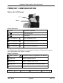
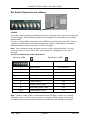
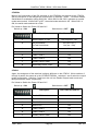
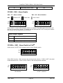
CASHFLOW® 952X / 952Xe / 9510 SELECTOR SYSTEMS USER GUIDE MEI., 2006 Rev: G4 PUBLISHED BY: MEI Internet: http://www.meigroup.com For further information on editions in other languages please contact the Technical Communications Manager at the above address. CashFlow® 952X / 952Xe / 9510 Selector Design Guide © , MEI UK International Ltd., 2006. All rights reserved Except as permitted under the relevant local legislation, no part of this publication may be copied, transmitted, transcribed, or distributed in any form or by any means, or stored in a database or retrieval system, or translated in any language (natural or computer), without the prior written permission of MEI. MEI®, CashFlow® and the MEI device are registered trademarks. MEI reserves the right to change the product or the product specifications at any time. While every effort has been made to ensure that the information in this publication is accurate, MEI disclaims any liability for any direct or indirect losses (howsoever caused) arising out of use or reliance on this information. This document does not necessarily imply product availability. ccTalk® - Money Controls This edition (January 2013) Printed in the USA. Note: Your product may differ slightly from some of the illustrations in this document. MEI., 2006 Page 2 Rev: G4 CashFlow 952X / 952Xe / 9510 User Guide MEI., 2006 Page 3 Rev: G4 CashFlow 952X / 952Xe / 9510 User Guide TABLE OF CONTENTS TABLE OF CONTENTS ............................................................................................................................... 4 SAFETY ......................................................................................................................................................... 6 WARNING ..................................................................................................................................................... 6 CAUTION ...................................................................................................................................................... 6 MAXIMUM OPERATING VOLTAGE .................................................................................................................. 6 DANGEROUS ENVIRONMENTS ........................................................................................................................ 6 DISPOSAL OF PRODUCT .................................................................................................................................. 6 CONFORMANCE TO INTERNATIONAL STANDARDS ........................................................................................... 6 SAFETY ...................................................................................................................................................... 7 PRODUCT IDENTIFICATION .................................................................................................................... 8 COMPATIBILITY ........................................................................................................................................ 9 PRODUCT FEATURES .............................................................................................................................. 10 DIAGNOSTIC LED (1) .................................................................................................................................. 11 ® IBUTTON MEMORY CONTACTS (2) ............................................................................................................. 11 SERVICE TOOL CONNECTOR (3) ................................................................................................................... 11 SERIAL INTERFACE CONNECTOR (HII OR CCTALK) (4) .................................................................................. 12 CF952X/CF952Xe ................................................................................................................................. 12 CF9510 ................................................................................................................................................. 12 DYNAMIC ROUTE INHIBIT CONNECTOR (5) ................................................................................................... 12 CONFIGURATION SWITCHES (6).................................................................................................................... 12 CF952Xe ............................................................................................................................................... 12 CF9510 ................................................................................................................................................. 12 MACHINE INTERFACE CONNECTOR (8) ......................................................................................................... 13 PRE-GATE STROBE AND DIRECTIONAL STROBES (9) ..................................................................................... 13 REJECT LEVER (10) ..................................................................................................................................... 13 SEPARATOR CONNECTOR (11) ..................................................................................................................... 13 CF952X/CF952Xe ................................................................................................................................. 13 CF9510 ................................................................................................................................................. 13 COIN ENTRY MOUNTING OPTIONS ..................................................................................................... 14 COIN ENTRY BEZELS ................................................................................................................................... 14 Y-CHUTE COMPONENTS .............................................................................................................................. 15 INSTALLATION ......................................................................................................................................... 16 SIDE ENTRY MOUNTING .............................................................................................................................. 16 TOP ENTRY MOUNTING ............................................................................................................................... 17 CASHFLOW 9528/9528E SYSTEM MOUNTING ............................................................................................... 18 REMOVAL OF MANIFOLD AND COLLAR PLATE .............................................................................................. 19 REMOVAL OF Y-CHUTE ................................................................................................................................ 19 MACHINE INTERFACE CONNECTOR .................................................................................................. 20 ACCEPTANCE TEST ................................................................................................................................. 22 AFTER INSTALLING THE VALIDATOR ............................................................................................................ 22 TESTING FOR ACCEPTANCE.......................................................................................................................... 22 COIN ROUTING CF952X/CF952Xe .......................................................................................................... 23 COIN ROUTING COMPATIBILITY ................................................................................................................... 24 ROUTE INHIBIT CONNECTOR........................................................................................................................ 25 DUMMY HEADING .........................................................................................................................................25 MEI., 2006 Page 4 Rev: G4 CashFlow 952X / 952Xe / 9510 User Guide PRODUCT CONFIGURATION ................................................................................................................. 26 WHAT IS THE LED DOING?.......................................................................................................................... 26 Normal Operations ................................................................................................................................ 26 DIL Switch Teach Operations ................................................................................................................ 26 iButton® Functions ................................................................................................................................ 26 DIL SWITCH OPTIONS FOR THE VALIDATOR .................................................................................................. 27 CF952X ................................................................................................................................................. 27 CF952Xe ............................................................................................................................................... 28 CF9510 ................................................................................................................................................. 28 CF952X - SW1 - ALARM ENABLE ................................................................................................................ 29 CF952XE - SW1 - ALARM ENABLE/CCTALK .............................................................................................. 29 CF9510 - SW1 - PARALLEL/BCO MODE SELECT .......................................................................................... 30 CF952X - SW2 - HII STANDALONE MODE (SERIAL MODE ONLY) ................................................................. 31 CF952XE - SW2 – SERIAL MODE ENABLE ................................................................................................... 31 CF9510 - SW2 - EXTENDED FEATURES (MULTIPULSE/EXTENDED BCO)........................................................ 31 SW3 - ENABLE COIN TEACH AND SW4 - INHIBIT COIN TEACH ...................................................................... 32 SW5 - TOKEN 1 TEACH AND SW6 TOKEN 2 TEACH ....................................................................................... 33 SW7 AND SW8 – ROUTE TEACH .................................................................................................................. 34 Route Teach Procedure ......................................................................................................................... 36 CF9510 - SW7 - PARALLEL OUTPUT TEACH ................................................................................................. 37 CF9510 - SW8 - MULTI-PULSE TEACH ........................................................................................................ 37 USING THE iBUTTON® ............................................................................................................................. 38 USER OPERATION ........................................................................................................................................ 39 CONCEPT .................................................................................................................................................... 39 CONFIGURING THE IBUTTON® ...................................................................................................................... 40 USING THE IBUTTON® TO PROGRAM ............................................................................................................. 40 MAINTENANCE ......................................................................................................................................... 41 PRODUCT SUPPORT ................................................................................................................................. 42 MEI., 2006 Page 5 Rev: G4 CashFlow 952X / 952Xe / 9510 User Guide SAFETY Warning Before cleaning, servicing, removing or replacing CashFlow® units ALWAYS SWITCH OFF or ISOLATE the ELECTRICITY SUPPLY to the host machine. Caution This guide is recommended for use by personnel trained to carry out electrical installation. Maximum Operating Voltage Do not apply more than the voltage specified on the unit, and within the following: Full Operating Voltage range: +10V to +15V DC (+12V nominal) and 22V to 27V DC (24V nominal) for CF9510 Supply Voltage Ripple: Within Vmin to Vmax up to 100Hz, <250mV pk - pk for Frequency>100Hz Current consumption: Quiescent current: 100mA Max Accept Gate: 800mA Max current: 2.3A Max CF9524/CF9524e 3.0A Max CF9528/CF9528e Dangerous Environments Do not operate the unit in the presence of flammable gasses or fumes, or after the entry of fluid into the machine. Disposal of Product Always dispose of defective units according to local regulations. Conformance to International Standards When installed and operated according to the instructions provided for the particular unit, CashFlow® products meet the applicable international and national safety standards for any country in which they are used. MEI., 2006 Page 6 Rev: G4 CashFlow 952X / 952Xe / 9510 User Guide SAFETY All electrical connections to the product must be rated according to the requirements for “Accessible SELV” circuits as defined in EN60335-1. The product is therefore suitable for use in a class 2 (non-earthed or non-grounded) appliance. Overcurrent protection is not included in the product and should be provided as part of the host machine. The recommended fuse value at the rated supply of 12V is: 3A Slow blow (to EN60127) Other protection methods may be used providing their overcurrent characteristics remain within the overall operating characteristics of the above fuse. Warning: This is a class A product. In a domestic environment this product may cause radio interference, in which case the user may be required to take adequate measures. MEI., 2006 Page 7 Rev: G4 CashFlow 952X / 952Xe / 9510 User Guide PRODUCT IDENTIFICATION MEI has manufactured coin mechanisms compatible with gaming and amusement machines for a number of years. Over this time the functionality of the range has been enhanced to match the market needs and whilst maintaining mechanical compatibility. ® The products detailed in this handbook relate to the CashFlow 95xx Series. To ensure you have the right product for your application please read this section. ® CashFlow 9520/9520e/9510 Supports 4 way Separator (optional, not available on the CF9510) Supports 8 way Separator (optional, not available on the CF9510) Available as Direct Entry, Side Entry or Top Entry CashFlow® 9524/9524e ® CashFlow 9520/9520e plus 4 way Separator, available as Side Entry, Top Entry or System Product MEI., 2006 Page 8 CashFlow® 9528/9528e CashFlow® 9520/9520e plus 8 way Separator, available as Top Entry or System Product Rev: G4 CashFlow 952X / 952Xe / 9510 User Guide COMPATIBILITY CashFlow® 111 & CashFlow® 9520 CashFlow® 115 CashFlow® 9520e CashFlow® 126 CashFlow® 9524 CashFlow® 9524e CashFlow® 129 CashFlow® 9528 CashFlow® 9528e CashFlow® 130 MEI., 2006 CashFlow® 9510 Page 9 Rev: G4 CashFlow 952X / 952Xe / 9510 User Guide PRODUCT FEATURES 10 i™Button Memory 1 2 9 3 8 4 7 5 11 Key: 1 Diagnostic Bi-colour LED 2 iButton® Memory Contacts 3 Support Tool Connector (i.e. CPM – Cashflow Programing Module) 4 a) Serial Interface Connector (HII) on CF952X 6 b) Serial Interface Connector (HII/ccTalk®) on CF952Xe c) STD212, 12V 10-way Open Collector Parallel Interface on CF9510 5 Route Inhibit Connector (not available in CF9510) 6 Configuration Switches (8 way DIL) 7 Post-gate and Directional Strobes 8 Machine Interface Connector (CF952X/CF952Xe only, Dual polarity and BCO) 9 Pre-gate Strobe 10 Reject Lever 11 a) Separator Connector for CF952X/CF952Xe Series b) STD 124, 24V 16-way Open Collector Parallel Interface for CF9510 MEI., 2006 Page 10 Rev: G4 CashFlow 952X / 952Xe / 9510 User Guide Diagnostic LED (1) The bi-colour LED fitted to the CashFlow® CF952X/CF952Xe/CF9510 series validator indicates it’s operational and configuration status by way of colour code flashes. For normal operation, refer to the table below. Normal Operation LED Codes OFF No power on product G Unit Working OK R Unit Faulty When a Coin is Inserted Example: LED Key = G G 1 x Flashes G Coin Accepted by Unit R 2 x Flashes G Coin Unrecognised by Unit R 3 x Flashes G Coin Inhibited by Unit R 4 x Flashes G Coin Inhibited by Machine 1 x Flashes OFF G G Green LED flashes once then LED turns to solid Green ON Green ON G Green Flashing R Red Flashing iButton® Memory Contacts (2) The iButton® memory (when placed onto the iButton® contacts) allows, routing and inhibit configuration data settings to be transferred from one CF952X/CF952Xe validator to another. This feature is currently not available in the CF9510. Service Tool Connector (3) This 6-way connector is primarily used with the MEI service tool i.e. CPM and provides a simple way of re-programming the validator whilst in the machine. Note: MEI Support Tools (CPM) will not work if the CF952Xe is in ccTalk mode MEI., 2006 Page 11 Rev: G4 CashFlow 952X / 952Xe / 9510 User Guide Serial Interface Connector (HII or ccTalk) (4) CF952X/CF952Xe This 10-pin connector provides a serial interface to an HII interface or ccTalk® for the CF952X and CF952Xe series. The serial mode is selected via the 8 way DIP switch. Refer to the CF952Xe Series Product Specification for details about the command set implementation in support of the ccTalk® interface. CF9510 This connector provides access to the STD212 12V, 10-pin dual inline interface. It provides the following input/output signals: Supply Voltage Input (12 volts) A to F Coin Outputs (output signal) All Inhibit signal (input signal) Escrow Return Signal (output signal) Dynamic Route Inhibit Connector (5) This is a 9-pin connector that provides input from the machine to the validator. Its function is to modify coin routing. When a specific exit is full, the host machine will signal to the validator to redirect subsequent coins to an overflow route. E.g. If a specific exit route becomes full, the machine will send a signal to the validator instructing it to route any further coins to an alternative exit route. This feature is not available in the CF9510 as the product does not support a Separator. Configuration Switches (6) The 8 way dual in line (DIL) switch provide a way to manually configure the validator. The following configurations can be achieved. Setting the alarm on or off Selecting dedicated serial HI2 operation Enable or Inhibit coins and tokens Teaching of tokens Teaching of primary, secondary and tertiary routes CF952Xe The 8 way dual in line switch behaves slightly differently in the CF952Xe. In these models, SW2 selects serial mode. Once in serial mode, SW1 is used to then select between HII or ccTalk. If SW2 is off, SW 1 reverts to Alarm Enable/Disable functionality. CF9510 In this variant, DIL switches 3 through 6 are identical to the CF952X/CF952Xe series. However, switches 1,2 and 7, 8 have different functions. Switches 1 and 2 select the active output mode, switch 7 selects parallel output teach, and switch 8 selects multi-pulse teach mode. MEI., 2006 Page 12 Rev: G4 CashFlow 952X / 952Xe / 9510 User Guide Machine Interface Connector (8) This 17-way connector provides power to the validator. This connector carries the coin inhibit and coin outputs signals to and from the machine. The connector provides the following input and outputs signals: Supply Voltage Input (12 volts) A to F Coin Outputs (output signal) A to F Coin Inhibits (input signal) Coin Output Common (input signal) Output Mode (input signal) This connector is not available on the CF9510. Pre-Gate Strobe and Directional Strobes (9) The pre-gate stobe detects obstructions around the accept gate. If an obstruction is detected then coin acceptance is inhibited until the obstruction is cleared. Directional strobes detect unauthorised entry of a coin for example, a coin or token entering through the bottom of the Unit. Reject Lever (10) The reject lever has two uses: To clear coins jammed in the validators coin path To confirm programming operation Separator Connector (11) CF952X/CF952Xe This connector is used to connect the validator to the separator on the CF952X and CF952Xe series. CF9510 On the CF9510, this connector is used as the STD124 Open-collector Parallel interface. It provides the following input/output signals : Supply Voltage Input (24Vnom) A to F Coin Outputs (output signal) A to F Coin Inhibits (input signal) Escrow Return Signal (output signal) All Inhibit signal (input signal) MEI., 2006 Page 13 Rev: G4 CashFlow 952X / 952Xe / 9510 User Guide COIN ENTRY MOUNTING OPTIONS There are a number of accessories available for the CashFlow® CF952X/CF952Xe/CF9510 series products. These accessories allow for easy mounting of the product to a wide range of machines. The Entry Bezel and the Y-Chute options can be used with either the CashFlow 9524/9524e and 9528/9528e top entry mechanisms. ® The CashFlow® 9524/9524e can be supplied for short channel mounting provided the machine has the appropriate mounting points for the bezel and Y-chute to be fitted. Coin Entry Bezels There are two entry bezel options available. The single coin option is used in coin only applications and the dual coin/token. Both versions incorporate a reject button that allows the return of jammed coin/tokens. Single coin bezel Coin/Token Bezel Coin Entry Bezels - Side View MEI., 2006 Page 14 Rev: G4 CashFlow 952X / 952Xe / 9510 User Guide Y-Chute Components Two Y-chute options are available that are used in conjunction with the coin entry bezels. One type includes electronics with back illumination of the dual coin/token entry bezel (DCE) and the other has no electronics particularly suitable for coin only applications. Fluid Duct Electronic Y-Chute Coin Only Y-Chute The overall design of both Y-chutes is the same, with the addition of electronics for back illumination being used with the dual coin/token option. Illumination Bulbs DCE Y-chute The two Y-chutes already referred to can both be used with the short channel version, but care must be taken to ensure that the required gap is maintained between the Y-chute reject arm link and the reject lever of the coin mechanism. Dual coin/token Y-chute with electronics Non-electric Y-chute To host machine To host machine Coin/token inhibit signals To validator To validator Coin Only Set-up Controller Set-up In a coin only application the interface loom from the machine goes directly to the validator. The use of the dual coin/token application requires a different loom, which connects as shown above. MEI., 2006 Page 15 Rev: G4 CashFlow 952X / 952Xe / 9510 User Guide INSTALLATION There are two types of machine mounting methods available, “Side Entry and Top Entry”. For side entry products the machine must have fitted a MEI front plate, for top entry mounting a metal channel is used. ® Installing or removing the CashFlow product from your machine can be done by following these simple instructions. Connect the separator loom to the connector at the base of the validator and locate the rectangular boss on the top of the separator into the base of the validator. Firmly screw the separator fixing lugs onto the rear of the validator. Having ensured that the front plate has a firm location onto the front of the machine, insert the side of the validator onto the two round bosses at the rear of the front plate and push firmly together until the two retaining clips are fully engaged. Side Entry Mounting ® When installing the CashFlow 9500 front entry product, it will be fitted to a MEI front plate and the following instructions will always apply. Having ensured that the front plate has a firm location onto the front of the machine, insert the side of the validator onto the two round bosses at the rear of the front plate and push firmly together until the two retaining clips are fully engaged. Retaining Clips Bosses Fixing Lugs Separator Loom Note: Your product may differ slightly from some of the illustrations in this document. MEI., 2006 Page 16 Rev: G4 CashFlow 952X / 952Xe / 9510 User Guide Top Entry Mounting The mounting channel for the CashFlow® 9524/9524e top entry product is supplied by the machine manufacturer, and therefore some variations may exist from machine to machine, however in principle these instructions still apply. When mounted into a channel the product must be fully assembled and ready for use, with only the machine interface loom to be connected. The mounting points indicated must be firmly seated into the channel and a gap of between 2-3 mm left between the reject lever and the reject arm from the machine. This small gap will ensure that the validator lid is able to fully close when the reject button on the machine has been pressed and released. 2 - 3 mm Gap Reject Lever Validator Lid Machine Interface Connector Mounting Holes Mounting Point Note: Your product may differ slightly from some of the illustrations in this document. MEI., 2006 Page 17 Rev: G4 CashFlow 952X / 952Xe / 9510 User Guide Cashflow 9528/9528e System Mounting The CashFlow® 9528/9528e system consists of a channel, Y-chute, validator, 8-way separator, manifold and tube collar plate. This is supplied as a complete system, but should you need to replace any part of it do so only in a set sequence, starting from near the top. Note: The Y-chute can, of course, be removed first, but it is not necessary to do so just to access the other modules. Note: Your product may differ slightly from some of the illustrations in this document. Ensure that power is turned off, not only to the validator, but also to the Y-chute if live. Disconnect machine interface loom, and the route inhibit connector. Disengage the release catch and lift the validator and separator upwards out of the mounting points. Pull the validator and separator forwards clear of channel. MEI., 2006 Page 18 Rev: G4 CashFlow 952X / 952Xe / 9510 User Guide Removal of Manifold and Collar Plate The manifold is supported in position by four lugs which slot into the side plates of the channel. It is retained there by two catches, as is the collar plate at the bottom. Manifold Release Catches Collar Plate Release Catches Removal of Y-chute Always disconnect the electrical connection first, if used, before removal of the Ychute. Pinch together the bottom ends of the Y-chute and lift upwards and to the right from the channel. Electrical Connection Pinch together and pull Upwards to the right MEI., 2006 Page 19 Rev: G4 CashFlow 952X / 952Xe / 9510 User Guide MACHINE INTERFACE CONNECTOR The interface to the validator from the machine is exactly the same as those that apply to the earlier MS/ME and CF1xx series validators, with the exception of pin 8 of the 17-way connector. Although the CF952X/CF952Xe series has a 17-way connector, it can accommodate a 15-way too. 17-way connector The table below shows a comparison between the 17-way and 15-way connector functions based on both MEI and BACTA definitions. 17- Way Connector 15 - Way Connector MEI Parallel Std Input or Output Pin No. BACTA BCO Std 1 - A coin o/p O/P 1 Ident signal 2 1 B coin o/p O/P 2 Accept o/p 5 3 2 Coin o/p Common I/P 3 Accept o/p Common 4 3 F coin o/p O/P 4 Accept o/p 1 5 4 Polarising Key 1 - 5 Polarising Key 6 5 E coin o/p O/P 6 Accept o/p 2 7 6 D coin o/p O/P 7 Accept o/p 3 8* 7 Output mode I/P 8 Select Line 9 8 C coin o/p O/P 9 Accept o/p 4 10 9 C coin inhibit I/P 10 Inhibit 4 11 10 +12V supply I/P 11 +12V supply 12 11 0V supply I/P 12 0V supply 13 12 D coin inhibit I/P 13 Inhibit 3 14 13 E coin inhibit I/P 14 Inhibit 2 15 14 F coin inhibit I/P 15 Inhibit 1 16 15 B coin inhibit I/P 16 Inhibit 5 17 - A coin inhibit I/P 17 Inhibit 6 Note: *The voltage applied to PIN 8 will result in either a parallel or BCO mode: For Parallel Mode – Apply a high voltage to PIN 8. (e.g. 5v up to a maximum 12 v) For BCO Mode – Apply a low voltage to PIN 8. (e.g. 0v) MEI., 2006 Page 20 Rev: G4 CashFlow 952X / 952Xe / 9510 User Guide This table shows the coin outputs and coin inhibits for particular coins. In this table, it shows the most common coin outputs and coin inhibits used for a UK currency validator. MEI., 2006 Coin Outputs Coin Inhibits and Currency and Currency A 5p A 5p B Token B Token C 10p C 10p D 20p D 20p E 50p E 50p & £2 F £1 F £1 Page 21 Rev: G4 CashFlow 952X / 952Xe / 9510 User Guide ACCEPTANCE TEST When the product is successfully mounted and connected to the machine, you will need to perform coin/token acceptance test. This test will confirm that the validator has been set up correctly. After Installing the Validator Press and release the reject button on the machine. Confirm that the lid on the front of the validator closes fully when the reject button is released. If it does not close fully, the validator cannot function properly (i.e. coin/token may be rejected). Test that power to the validator is on by checking that the green LED is fully lit. OFF No power on product G Unit working OK R Unit faulty Testing for Acceptance Insert into the machine a selection of coins/tokens to check that they are accepted by the validator. The green LED will flash off once to indicate a valid accepted coin/token. If the coin/token has been rejected refer to the table below. Example: LED Key: = MEI., 2006 G G 1 x Flashes G Coin Accepted by Unit R 2 x Flashes G Coin Unrecognised by Unit R 3 x Flashes G Coin Inhibited by Unit R 4 x Flashes G Coin Inhibited by Host Machine 1 x Flashes OFF G G Green LED flashes once then LED turns to solid Green ON Green ON G Green Flashing Page 22 R Red Flashing Rev: G4 CashFlow 952X / 952Xe / 9510 User Guide COIN ROUTING CF952X/CF952Xe This following diagrams show the coin exit paths for a routed coin. Coin Routing can be set using the configuration switches found on the front of the CF952X/CF952Xe. A primary, secondary, or tertiary route may be selected. Please refer to the configuration section relating to switches 7 and 8 combined. SW7 on = Primary, SW8 on = Secondary, SW7 and SW8 on = Tertiary. Illustrated here are the switch setting for selecting Tertiary. = Switch OFF KEY = Switch ON =Don’t Care ON OFF 1 2 3 4 5 6 7 8 Switches 7, 8 or both 7 & 8 are Used for Route Teach. Depending on the route inhibit status, the acceptor has 4 routing priorities. These are referred to as:- Default, Primary, Secondary and Tertiary. Only the Primary, Secondary and Tertiary can be taught using switches 7 and 8 or both 7 and 8. Notes: 1. If the primary route gets full, coins for that route will automatically go to the secondary route. 2. All CF952X/CF952Xe Validators leave the factory programmed with “all coins to the default route”. CF9524/CF9524e 4-WAY SEPARATOR Default Route = A CF9528/CF9528e 8-WAY SEPARATOR Default Route = 8 Cash Box Exits D 8 C 7 6 Coin Reject 1 A MEI., 2006 3 4 Coin Tube Exits B Default Route Default Route 2 5 Page 23 1 2 4 3 8 7 6 5 Rev: G4 CashFlow 952X / 952Xe / 9510 User Guide Coin Routing Compatibility In order that the CF952Xe fit into existing ccTalk installations, it is important that the coin routes mimic those of the Money Controls SR5. Therefore, routing is changed to be compatible to the SR5 when in ccTalk mode only, (SR5 mode) as shown below: Route Nos Exits 1 2 3 4 5 6 7 8 9524e d c a b C D B A 9528e 1 2 3 4 5 6 7 8 SR5 (4way) D C B A a b c d SR5 (8way) 1 2 4 3 8 7 6 5 For example, if the CF952Xe is in ccTalk mode and a coin is requested to exit from path B, the machine would have to send that coin to route 3. However, in HII mode, the route selected by the machine for exit B would be 4. MEI., 2006 Page 24 Rev: G4 CashFlow 952X / 952Xe / 9510 User Guide Route Inhibit Connector The route Inhibit connector, when used in parallel mode, gives a signal when specific exits, (external to the product) are in a “Full” condition. Signals from the machine ensure that, while the “Full” condition continues, further coins/tokens directed to that exit will be rerouted to an alternative exit. When in BCO or HI2 mode this will depend on the machine signal sent to the CF952X/CF952Xe. Notes: 1. In order to inhibit a particular route, 0V must be applied to its respective pin. 2. An alternative route must always be of a lower priority 9 Way Route Inhibit Connector Route inhibit connections are via a 9 way header from the standard PCB. This header is a single row of 9 pins on a 0.1 inch grid. The pin size is 0.025 inch square. Pin Description for (CF9528/CF9528e) Description for (CF9524/CF9524e ) 1 Full 1 (d) 2 Full 2 (c) 3 Full 3 (a) 4 Full 4 (b) 5 Full 5 C 6 Full 6 D 7 Full 7 B 8 Polarised Polarised 9 Ground Ground DUMMY HEADING MEI., 2006 Page 25 Rev: G4 CashFlow 952X / 952Xe / 9510 User Guide PRODUCT CONFIGURATION What is the LED Doing? LED ® iButton Normal Operations OFF No power on product G Unit working OK R Unit faulty G 1 x Flashes G Coin Accepted by Unit R 2 x Flashes G Coin Unrecognised by Unit R 3 x Flashes G Coin Inhibited by Unit R 4 x Flashes G Coin Inhibited by Machine DIL Switch Teach Operations The LED operation will depend on your configuration settings. Please see the relevant switch setting later in this section for details. ® iButton Functions CF952X/CF952Xe is programming the iButton® G Rapid x Flash G Rapid Flash iButton® programmed OK R Rapid Flash iButton® program error (re-try) G Rapid Flash iButton® programming a CF952X/CF952Xe G No error - program completed OK G LED Key: = MEI., 2006 OFF G Green ON G Green Flashing Page 26 R Red Flashing Rev: G4 CashFlow 952X / 952Xe / 9510 User Guide DIL Switch Options for the validator DIL Switches CF952X There are 8 teach switches located behind the cut out section of the reject cover (see item 6 on front page). These switches enable the key settings to be altered by way of unique teach modes. To enter a “Teach Mode”, the power of the CF952X may need to be turned OFF. Prior to using the relevant teach mode switches select the required “Teach Mode” (see table below) and then turn the power to the CF952X ON again. Note: Only one teach mode can be set at any one time. However switch 1 is used to set the alarm to either ON or OFF and is therefore independent of the other 7 switches. Do I Need to Switch the Power Off and On? Switch up = ON Switch down = OFF Description Turn Power Off and On 1 Alarm Enable 2 HII Standalone Mode Yes 3 Enable Coin Yes 4 Inhibit Coin Yes 5 Teach Token 1 Yes 6 Teach Token 2 Yes 7 Primary Route Teach Yes 8 Secondary Route Teach Yes Tertiary Route Teach Yes 7&8 Not Required Note: When in teach mode a 30-second timeout will apply. If there is no activity within this time or if an error has occurred, a red light will flash rapidly. In this case, no changes will have been made and you will need to start the teach process again. MEI., 2006 Page 27 Rev: G4 CashFlow 952X / 952Xe / 9510 User Guide CF952Xe Most of the functionality of the DIL switches on the CF952Xe are identical to the CF952X, with the exception of the assignment and behavior of switches 1 and 2. On these models, Serial Mode is enabled by setting SW2 ON. While SW2 is ON, SW1 operates as a serial mode select switch. When SW1 is OFF, the serial mode selected is HII. When SW1 is ON, the serial mode selected is ccTalk. Do I Need to Switch the Power Off and On? Switch up = ON Switch down = OFF Description Turn Power Off and On 1 Alarm Enable/ ccTalk 2 HII Serial Mode Yes (sw 1 OFF) CcTalk Serial Mode Yes (sw 1 ON) Not Required / Yes 3 Enable Coin Yes 4 Inhibit Coin Yes 5 Teach Token 1 Yes 6 Teach Token 2 Yes 7 Primary Route Teach Yes 8 Secondary Route Teach Yes CF9510 Again, the assigment of the switches is slightly different on the CF9510. While switches 3 through 6 remain the same as in the CF952X/CF952Xe, switches 1 and 2 select the output mode configuration. Switches 7 and 8 put the unit into Parallel Output teach mode and Multi-pulse teach mode, respectively. Do I Need to Switch the Power Off and On? Switch up = ON Switch down = OFF Description MEI., 2006 Turn Power Off and On 1 Parallel/BCO mode Yes 2 Extended Features Yes 3 Enable Coin Yes 4 Inhibit Coin Yes 5 Teach Token 1 Yes 6 Teach Token 2 Yes 7 Primary Route Teach Yes Page 28 Rev: G4 CashFlow 952X / 952Xe / 9510 User Guide Secondary Route Teach 8 Yes CF952X - SW1 - Alarm Enable SW1 - On - Alarm enabled SW1 - Off - Alarm disabled = Switch OFF KEY = Switch ON =Don’t Care ON ON OFF OFF 1 2 3 4 5 6 7 8 1 2 3 4 5 6 7 8 When switch 1 is set to ON the alarm feature is enabled. The Alarm will not be active until the first coin has been inserted. The Alarm can be switched ON or OFF at any time without the need to turn off the power to the CF952X. Alarm output signals Mode Output status Parallel All outputs on for >600ms BCO All outputs high except for output C CF952Xe - SW1 - Alarm Enable/ccTalk While switch 2 is OFF, SW1 behaves as the Alarm Enable switch. ON OFF 1 2 3 4 5 6 7 8 When SW2 is active, SW1 becomes the serial protocol selector. If SW1 is OFF, the serial mode selected is HII. If SW1 is ON, ccTalk is the serial protocol selected. ON ON OFF OFF 1 2 3 4 5 6 7 1 8 MEI., 2006 3 4 5 6 7 8 ccTalk selected HII selected 2 Page 29 Rev: G4 CashFlow 952X / 952Xe / 9510 User Guide CF9510 - SW1 - Parallel/BCO Mode select Together with SW2, SW1 is used to determine the active output mode as described in the following table: ON ON OFF OFF 1 2 3 4 5 6 7 ON ON OFF OFF 1 2 3 4 5 6 7 SW1 8 MEI., 2006 8 SW2 1 2 3 4 5 6 7 8 1 2 3 4 5 6 7 8 Active Mode OFF OFF Parallel ON OFF BCO ON ON Extended BCO OFF ON Mulitpulse Page 30 Rev: G4 CashFlow 952X / 952Xe / 9510 User Guide CF952X - SW2 - HII Standalone Mode (Serial Mode Only) ON OFF 1 2 3 4 5 6 7 8 This mode is intended for users that want to interface their machines using HI2 interface only. When switch 2 is set to ON, the CF952X will operate in serial mode only. This feature can be selected provided the validator power is cycled OFF and ON. In normal operation the parallel interface is master, however, with this switch set the serial HI2 is master. CF952Xe - SW2 – Serial Mode Enable As described in section CF952Xe - SW1 - Alarm Enable/ccTalk, SW2 enables Serial mode. Once enabled, SW1 then becomes the serial mode selector switch selecting between HII when switched OFF and ccTalk when switched ON. ON ON OFF OFF 1 2 3 4 5 6 7 1 8 2 3 4 5 6 7 8 ccTalk selected HII selected CF9510 - SW2 - Extended Features (Multipulse/Extended BCO) As described in the truth table in section CF9510 - SW1 - Parallel/BCO Mode select, SW2 together with SW1 determine the active output mode in accordance with the following table: SW1 MEI., 2006 SW2 Active Mode OFF OFF Parallel ON OFF BCO ON ON Extended BCO OFF ON Mulitpulse Page 31 Rev: G4 CashFlow 952X / 952Xe / 9510 User Guide SW3 - Enable Coin Teach and SW4 - Inhibit Coin Teach (Common to the CF952X, CF952Xe, and CF9510) Enable a Coin: Inhibit a Coin: ON ON OFF OFF 1 2 3 4 5 6 7 8 1 2 3 4 5 6 7 8 These switches change the state of the accepted coin(s) from Inhibited to Enabled and vice versa. Follow the instructions below to either Enable or Inhibit a coin(s): Step Light Operation and Action Required 1 Power Machine OFF To enable a coin set switch 3 to ON 2 To inhibit a coin set switch 4 to ON R 3 Slow Power Machine ON Insert coin(s) to be enabled or inhibited. 4 R G R R G G Inserted R coin recognised – OK Coin NOT recognised (re-insert coin) Set switch 3 to OFF - ends enable teach. 5 Set switch 4 to OFF - ends inhibit teach Coin G 6 R Rapid accepted Error - / Re-try inhibited teach - OK again. Note: The validator must accept any Coin inserted, so that it is firstly recognised before the action to enable or inhibit can be achieved. Enable / Inhibit Coin LED Light Codes R Slow Flash Insert coin sample in Unit R Rapid Flash Program error R G R Inserted coin recognised R G G G Inserted coin stored in memory 4 x Flashes LED Key = Inserted coin unrecognised R MEI., 2006 OFF G Green ON G Green Flashing Page 32 R Red Flashing Rev: G4 CashFlow 952X / 952Xe / 9510 User Guide SW5 - Token 1 Teach and SW6 Token 2 Teach (Common to the CF952X, CF952Xe, and CF9510) Token 1 Teach: SW5 On Token 2 Teach: SW6 On ON ON OFF OFF 1 2 3 4 5 6 7 8 1 2 3 4 5 6 7 8 The CF952X /CF952Xe/CF9510 allows you to teach up to two tokens, referred to as Token 1 and Token 2, into two separate channels. Follow the instructions below to teach a token. Step Light 1 Operation and Action Required Power Machine OFF To teach token 1 set switch 5 to ON 2 To teach token 2 set switch 6 to ON 3 R Slow Power Machine ON Insert sample tokens slowly (min. x 20). 4 5 G If the inserted token is recognised the green light will flash once. R When approx. 20 tokens have been inserted, Unit will flash the green light rapidly. Set switch 5 to OFF - ends token 1 teach. 6 Set switch 6 to OFF - ends token 2 teach Tokens G 7 LED Key: = MEI., 2006 R Rapid OFF G taught Error Green ON - G - Re-try teach Green Flashing R Page 33 OK again. Red Flashing Rev: G4 CashFlow 952X / 952Xe / 9510 User Guide SW7 and SW8 – Route Teach (Common to the CF952X and CF952Xe) ON ON OFF OFF 1 2 3 4 5 6 7 8 1 2 3 4 5 6 7 8 The acceptor has 4 or 8 coin routes depending on the route inhibit status, the first routes can be taught using switches 7 and 8. The order of priority is primary, secondary then tertiary. For example, if the primary route is full, the secondary route is then selected. On a CF9524/CF9524e 4-way separator, route 'a' is the default route and on CF9528/CF9528e 8-way separator route '8'. All CF952X/C952Xe acceptors leave the factory programmed with "all coins to the default route". To program a route, the reject lever needs to be pressed a specified number of times (see Table below). When in this mode the Green light will flash (cycle) the current route, followed by a single Red flash. Press the reject Lever the number of times for the coin route required and then Insert the Coin or Coins that requires routing. Examples: The acceptor starts at the normal default route for the separator fitted. Press Reject Lever to cycle down through the routes, i.e. one press per position. For example, by pressing Reject Lever once will select route ‘B’ on a CF9524 or route 7 on a CF9528. This will be visually indicated by the green LED flashing on and off seven times followed by the red LED flashing on and off once. Pressing Reject Lever twice will select route ‘D’ on a CF9524, or route 6 on a CF9528. This will be visually indicated by the green LED flashing on and off six times followed by the red LED flashing on and off once. Pressing Reject Lever three times will select route ‘C’ on a CF9524, or route 5 on a CF9528. This will be visually indicated by the green LED flashing on and off five times followed by the red LED flashing on and off once and so on. This pattern will be repeated until either the Reject Lever is pressed again, when the new route pattern will be displayed. If a coin is inserted then the green LED will flash if the coin is recognised, or the red LED will flash if the coin is not recognised. No of reject lever presses 0 1 2 3 4 5 6 7 No of green flash codes 8 7 6 5 4 3 2 1 Route selected (CF9524/CF9524e - 4 way) A B D C b a c d Route selected (CF9528/CF9528e - 8 way) 8 7 6 5 4 3 2 1 Route Inhibit Connector Pin No. 8 7 6 5 4 3 2 1 MEI., 2006 Page 34 Rev: G4 CashFlow 952X / 952Xe / 9510 User Guide Example: How to set a Primary route ‘C on a CF9524 (4-way separator) – see shaded areas 1. Power machine OFF 2. Set switch 7 to ON 3. Power machine ON 4. Press reject lever 3 times (light will cycle the following sequence) R G G G G Cycles 5. Insert required coins to be routed ON 6. Set switch 7 to OFF OFF 1 2 3 4 5 6 7 8 No of reject lever presses 0 1 2 3 4 5 6 7 No of green flash codes 8 7 6 5 4 3 2 1 4-way separator exit A B D C b a c d MEI., 2006 Page 35 Rev: G4 G CashFlow 952X / 952Xe / 9510 User Guide Route Teach Procedure Step Light Operation and Action Required 1 Power Machine OFF For primary route set switch 7 to ON For secondary route set switch 8 to ON 2 For tertiary route set switches 7 & 8 ON 3 R Slow Power Machine ON 4 R +? G Press reject lever the number of times for the requested route. Insert the coin for the required route. G G G G Inserted coin recognised - OK R R R R Coin NOT recognised (re-insert coin). 5 For primary route set switch 7 OFF. For secondary route set switch 8 OFF. 6 For tertiary route set switches 7 & 8 OFF. G 7 LED Key: - MEI., 2006 R Route taught - OK Rapid OFF Error - Re-try route teach again. G Green ON G Green Flashing Page 36 R Red Flashing Rev: G4 CashFlow 952X / 952Xe / 9510 User Guide CF9510 - SW7 - Parallel Output Teach On the CF9510, SW7 is entered by setting SW7 ON, and turning the unit ON. The principle for this is the same as the route teach operation on the CF952X series acceptor. The LED will blink green a number of times followed by one red blink. The number of green blinks equates to the output to be set and can be changed by pressing the reject lever as defined in the following table: Number of Reject Lever Presses 0 1 2 3 4 5 N° Of Green Flash Code 1 2 3 4 5 6 Output Selected A B C D E F Once the desired output is selected, then the coin whose output is to be taught should be dropped into the acceptor. Mulitple coins outputs can be taught in one teach session. CF9510 - SW8 - Multi-pulse Teach On the CF9510, SW8 is used to enter Multi-pulse Teach Mode. As with Parallel Output Teach Mode, the unit must be power-cycled for the switch setting to be acknowledged. Again, for this operation, the LED will blink green a number of times followed by one red blink. The number of green blinks equates to the number of pulses to be set and can be changed by pressing the reject lever. The maximum number of pulses that can be set via the MMI for each coin is 4. However 8 can be set using the support tool, if necessary. MEI., 2006 Number of Reject Lever Presses 0 1 2 3 N° Of Green Flash Code 1 2 3 4 Number of Pulses Selected 1 2 3 4 Page 37 Rev: G4 CashFlow 952X / 952Xe / 9510 User Guide USING THE iBUTTON® The iButton® is a memory device used to transfer coin routes and inhibit information from one CF952X/CF952Xe acceptor to another. There is no routing plug required, with all routing information held in the validator. This feature is not currently available on the CF9510 since this unit does not support a Separator. The iButton® stores data which when read by the acceptor will update it with respect to the coin routes and coin inhibits. All of these functions will take effect when the acceptor detects that an iButton® has been placed on the contacts on the lid. Note: The CF952X/CF952Xe does not use routing plugs. See iButton® Functions on page 26 for the LED functions. MEI., 2006 Page 38 Rev: G4 CashFlow 952X / 952Xe / 9510 User Guide User Operation The read/write process is started when the acceptor detects that an iButton® has been placed on the contact pads located on the front. The LED will indicate this by flashing the LED green. ® If the iButton type is not supported, then the software will indicate this by flashing the LED Red. Concept iButton® - (Before) ? Field Base CF952X/CF952Xe Data not known ® within this iButton memory ® iButton - (After) iButton® new data now: CF952X/CF952Xe Pays Out 10c, 20c, 50c,1€ & 2€ Routes Coins 10c to Exit A CF952X/CF952Xe Pays Out 20c to Exit B 10c, 20c, 50c,1€ & 2€ 50c to Exit C Routes Coins 1€ & 2€ to Exit D 10c to Exit A 20c to Exit B 50c to Exit C 1€ & 2€ to Exit D Now use the iButton® to program the Field Base CF952X/CF952Xe Validators with the same configuration. See Configuring the iButton® on page 40. MEI., 2006 Page 39 Rev: G4 CashFlow 952X / 952Xe / 9510 User Guide Configuring the iButton® The procedure below explains how to program the iButton® from a known CF952X/CF952Xe. Step Light 1 Operation and Action Required Press and hold down the reject lever. 2 G Rapid Place iTM Button on to iButton® contacts. 3 G Slow Light will flash, also Accept Gate will buzz. 4 Remove iButton® from contacts. 5 Release the reject lever. ® iButton programmed OK G 6 R Rapid Error iButton ® not programmed (re-try). Using the iButton® to Program How to program a CF952X/CF952Xe using the iButton Step Light 1 G 2 G 3 G Slow LED Key: = MEI., 2006 Operation and Action Required Place iButton® on to iButton® contacts. Light will flash and Accept Gate will click. Slow ® Remove iButton from contacts. Press the reject lever to confirm. Accept Gate will click then release the reject lever. 4 5 ® G CF952X/CF952Xe programmed OK R Error - CF952X/CF952Xe failed programming (re-try). OFF G Green ON G Green Flashing Page 40 R Red Flashing Rev: G4 CashFlow 952X / 952Xe / 9510 User Guide MAINTENANCE Note: The practical maintenance that can be carried out is limited to cleaning the areas of the validator that the coins travel through, and the replacement of the coin entry liner if it becomes worn. All other servicing should be carried out at your approved service centre. The cleaning should be carried out on a regular basis of at least once a month. The shaded areas shown below are those to be cared for. The coin entry liner is accessed by unscrewing the coin entry moulding at the top of the validator. The coin entry liner can then be eased off with the aid of a fine screwdriver, and a replacement slid into place. Cleaning and maintenance must only be carried out by suitably trained personnel. Cleaning must only be carried out after power has been removed from the product. Never use a cleaner containing solvents, scrapers or abrasive materials. Never apply water or cleansers directly onto the product. Always apply them to a clean cloth first, and not too liberally, so that the cloth used is only moist. Coin Entry Moulding Coin Entry Liner Clean Shaded Area MEI., 2006 Page 41 Rev: G4 PRODUCT SUPPORT In addition to the MEI offices around the world an international network of Distributors and Approved Service Centres can offer you technical support and other services as well. These services include repairs, re-programming of your CashFlow® products with new coinsets, replacing damaged modules, and the supply of a range of spare parts. Visit the MEI web site for your local support: WWW.MEIGROUP.COM MEI., 2006 Page 42 Rev: G4