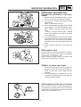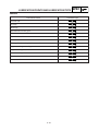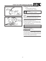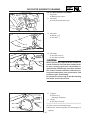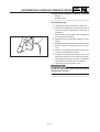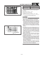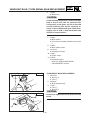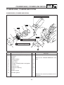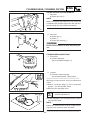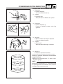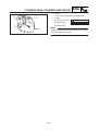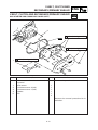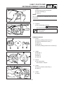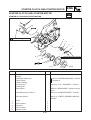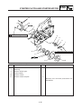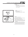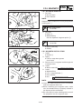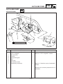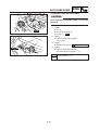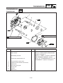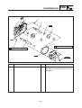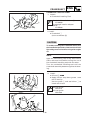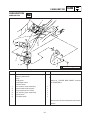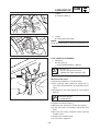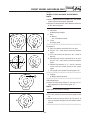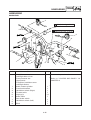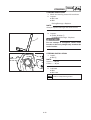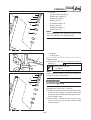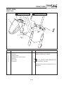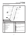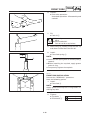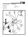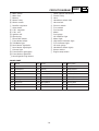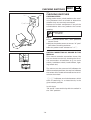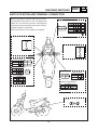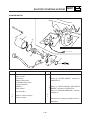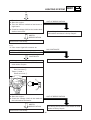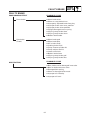
1
YW50AP
LIT-11616-15-39
5PJ-F8197-10
EB000000
YW50AP
SERVICE MANUAL
©2001 by Yamaha Motor Corporation U.S.A.
First edition, November 2001
All rights reserved.
Any reprinting or unauthorized use
without the written permission of
Yamaha Motor Corporation U.S.A.
is expressly prohibited.
P/N LIT-11616-15-39
EB001000
NOTICE
This manual was produced by the Yamaha Motor Company, Ltd. primarily for use by Yamaha dealers and their qualified mechanics. It is not possible to include all the knowledge of a mechanic in
one manual. Therefore, anyone who uses this book to perform maintenance and repairs on Yamaha
vehicles should have a basic understanding of mechanics and the techniques to repair these types
of vehicles. Repair and maintenance work attempted by anyone without this knowledge is likely to
render the vehicle unsafe and unfit for use.
Yamaha Motor Company, Ltd. is continually striving to improve all of its models. Modifications
and significant changes in specifications or procedures will be forwarded to all authorized Yamaha
deal-ers and will appear in future editions of this manual where applicable.
NOTE:
Designs and specifications are subject to change without notice.
IMPORTANT MANUAL INFORMATION
Particularly important information is distinguished in this manual by the following.
Q
The Safety Alert Symbol means ATTENTION! BECOME ALERT! YOUR
SAFETY IS INVOLVED!
w
Failure to follow WARNING instructions could result in severe injury or death
to the scooter operator, a bystander or a person checking or repairing the
scooter.
cC
A CAUTION indicates special precautions that must be taken to avoid damage to the scooter.
NOTE:
A NOTE provides key information to make procedures easier or clearer.
HOW TO USE THIS MANUAL
This manual is intended as a handy, easy-to-read reference book for the mechanic. Comprehensive
explanations of all installation, removal, disassembly, assembly, repair and check procedures are
laid out with the individual steps in sequential order.
1 The manual is divided into chapters. An abbreviation and symbol in the upper right corner of
each page indicate the current chapter. Refer to “SYMBOLS”.
2 Each chapter is divided into sections. The current section title is shown at the top of each
page, except in Chapter 3 (“PERIODIC CHECKS AND ADJUSTMENTS”), where the sub-section title(s) appears.
3 Sub-section titles appear in smaller print than the section title.
4 To help identify parts and clarify procedure steps, there are exploded diagrams at the start of
each removal and disassembly section.
5 Numbers are given in the order of the jobs in the exploded diagram. A circled number indicates a disassembly step.
6 Symbols indicate parts to be lubricated or replaced. Refer to “SYMBOLS”.
7 A job instruction chart accompanies the exploded diagram, providing the order of jobs, names
of parts, notes in jobs, etc.
8 Jobs requiring more information (such as special tools and technical data) are described sequentially.
2
1
4
3
6
5
7
8
1
2
EAS00009
SYMBOLS
GEN
INFO
SPEC
3
The following symbols are not relevant to every vehicle.
Symbols 1 to 8 are designed as thumb tabs
to indicate the chapter’s number and content.
1 General information
2 Specifications
3 Periodic inspection and adjustment
4 Engine
5 Carburetor(s)
6 Chassis
7 Electrical system
8 Troubleshooting
4
INSP
ADJ
ENG
5
6
CHAS
CARB
7
8
–
ELEC
TRBL
SHTG
+
9
0
q
w
e
r
Symbols 9 to y indicate the following.
9 Serviceable with engine mounted
0 Filling fluid
q Lubricant
w Special tool
e Tightening torque
r Wear limit, clearance
t Engine speed
y Electrical data
T.
R.
t
y
u
i
G
E
p
o
M
a
B
s
M
LS
d
f
LT
New
Symbols u to s in the exploded diagrams indicate the types of lubricants and lubrication
points.
u Engine oil
i Gear oil
o Molybdenum disulfide oil
p Wheel bearing grease
a Lithium soap base grease
s Molybdenum disulfide grease
Symbols d to f in the exploded diagrams
indicate the following.
d Apply locking agent (LOCTITE ®)
f Replace the part
INDEX
GENERAL INFORMATION
1
SPECIFICATIONS
2
PERIODIC INSPECTION AND
ADJUSTMENT
3
ENGINE OVERHAUL
4
CARBURETION
5
CHASSIS
6
–
+
ELECTRICAL
7
TROUBLESHOOTING
8
CHAPTER 1.
GENERAL INFORMATION
SCOOTER INDENTIFICATION ........................................................................................................... 1-1
VEHICLE IDENTIFICATION NUMBER ........................................................................................... 1-1
MODEL CODE ................................................................................................................................ 1-1
IMPORTANT INFORMATION ............................................................................................................ 1-2
PREPARATION FOR REMOVAL AND DISASSEMBLY ................................................................ 1-2
REPLACEMENT PARTS ................................................................................................................. 1-2
GASKETS, OIL SEALS AND O-RINGS.......................................................................................... 1-2
LOCK WASHERS/PLATES AND COTTER PINS ........................................................................... 1-2
BEARINGS AND OIL SEALS ......................................................................................................... 1-3
CIRCLIPS ........................................................................................................................................ 1-3
CHECKING OF CONNECTIONS ........................................................................................................ 1-4
HOW TO USE THE CONVERSION TABLE ....................................................................................... 1-5
CONVERSION TABLE .................................................................................................................... 1-5
SPECIAL TOOLS ................................................................................................................................ 1-6
CHAPTER 2.
SPECIFICATIONS
GENERAL SPECIFICATION ............................................................................................................... 2-1
MAINTENANCE SPECIFICATION ..................................................................................................... 2-4
ENGINE .......................................................................................................................................... 2-4
TIGHTENING TORQUES ............................................................................................................... 2-6
ENGINE .......................................................................................................................................... 2-6
MAINTENANCE SPECIFICATION ..................................................................................................... 2-7
CHASSIS ........................................................................................................................................ 2-7
TIGHTENING TORQUES ............................................................................................................... 2-8
CHASSIS ........................................................................................................................................ 2-8
MAINTENANCE SPECIFICATION ..................................................................................................... 2-9
ELECTRICAL ................................................................................................................................... 2-9
GENERAL TORQUE SPECIFICATIONS ........................................................................................... 2-11
LUBRICATION POINTS AND LUBRICATION TYPE ....................................................................... 2-12
ENGINE ........................................................................................................................................ 2-12
CHASSIS ...................................................................................................................................... 2-13
CABLE ROUTING ............................................................................................................................. 2-14
CHAPTER 3.
PERIODIC INSPECTION AND ADJUSTMENTS
INTRODUCTION ................................................................................................................................ 3-1
PERIODIC MAINTENANCE/LUBRICATION INTERVALS ................................................................ 3-1
COVER AND PANEL .......................................................................................................................... 3-3
SIDECOVER AND SEAT ................................................................................................................ 3-3
LOWER COWLING, UPPER COVER, LEG SHIELD 1, 2 AND FOOTREST BOARD ..................... 3-4
HANDLEBAR COVER(FRONT AND REAR) ................................................................................... 3-5
ENGINE .............................................................................................................................................. 3-6
IDLE SPEED ADJUSTMENT .......................................................................................................... 3-6
THROTTLE CABLE FREE ADJUSTMENT ..................................................................................... 3-7
AUTOLUBE PUMP AIR BLEEDING ............................................................................................... 3-8
SPARK PLUG INSPECTION ........................................................................................................... 3-9
ENGINE OIL LEVEL INSPECTION ............................................................................................... 3-10
TRANSMISSION OIL REPLACEMENT ........................................................................................ 3-11
AIR FILTER ELEMENT CLEANING .............................................................................................. 3-12
V-BELT INSPECTION ................................................................................................................... 3-14
CHASSIS .......................................................................................................................................... 3-15
FRONT BRAKE LEVER FREE PLAY CHECK ................................................................................ 3-15
REAR BRAKE LEVER FREE PLAY CHECK................................................................................... 3-15
BRAKE PAD INSPECTION ........................................................................................................... 3-15
BRAKE SHOE INSPECTION ........................................................................................................ 3-16
BRAKE FLUID LEVEL INSPECTION ............................................................................................ 3-16
AIR BLEEDING (HYDRAULIC BRAKE SYSTEM) ........................................................................ 3-17
STEERING ADJUSTMENT .......................................................................................................... 3-18
TIRE INSPECTION ........................................................................................................................ 3-19
WHEEL INSPECTION ................................................................................................................... 3-22
FRONT FORK INSPECTION ......................................................................................................... 3-22
REAR SHOCK ABSORBER INSPECTION .................................................................................... 3-22
SEAT LOCK CABLE ADJUSTMENT ........................................................................................... 3-22
CABLE CHECKING AND LUBRICATING ..................................................................................... 3-23
LEVERS LUBRICATING ............................................................................................................... 3-23
CENTERSTAND LUBRICATING .................................................................................................. 3-23
ELECTRICAL ..................................................................................................................................... 3-24
BATTERY INSPECTION ............................................................................................................... 3-24
FUSE INSPECTION ...................................................................................................................... 3-29
HEADLIGHT BEAM ADJUSTMENT ............................................................................................ 3-30
HEADLIGHT BULB REPLACEMENT ............................................................................................ 3-30
TURN SIGNAL AND TAILLIGHT BULB REPLACEMENT ........................................................... 3-31
TAILLIGHT BULB REPLACEMENT .............................................................................................. 3-32
LICENSE LIGHT BULB REPLACEMENT...................................................................................... 3-32
CHAPTER 4.
ENGINE
ENGINE OVERHAUL ......................................................................................................................... 4-1
WIREHARNESS AND CABLES ...................................................................................................... 4-1
CYLINDER HEAD, CYLINDER AND PISTON .................................................................................... 4-3
CYLINDER HEAD, CYLINDER AND PISTON ................................................................................ 4-3
PISTON PIN AND PISTON REMOVAL .......................................................................................... 4-4
CYLINDER HEAD INSPECTION ..................................................................................................... 4-4
CYLINDER AND PISTON INSPECTION ........................................................................................ 4-5
PISTON RINGS INSPECTION ........................................................................................................ 4-7
PISTON PIN AND PISTON PIN BEARING .................................................................................... 4-7
PISTON PIN AND PISTON INSTALLATION ................................................................................. 4-8
CYLINDER AND CYLINDER HEAD ................................................................................................ 4-9
V-BELT, CLUTCH AND SECONDARY/PRIMARY SHEAVE ........................................................... 4-11
KICK STARTER AND CRANKCASE COVER(LEFT)..................................................................... 4-11
KICK STARTER ............................................................................................................................. 4-12
KICK STARTER INSTALLATION ................................................................................................. 4-13
V-BELT, CLUTCH AND SECONDARY/PRIMARY SHEAVE ........................................................ 4-14
SECONDARY SHEAVE ................................................................................................................ 4-15
PRIMARY SHEAVE REMOVAL .................................................................................................... 4-16
SECONDARY SHEAVE REMOVAL.............................................................................................. 4-16
CLUTCH INSPECTION ................................................................................................................. 4-17
V-BELT INSPECTION ................................................................................................................... 4-18
PRIMARY SHEAVE INSPECTION ................................................................................................ 4-19
SECONDARY SHEAVE ................................................................................................................ 4-20
SECONDARY SHEAVE INSTALLATION ..................................................................................... 4-21
PRIMARY SHEAVE ...................................................................................................................... 4-22
STARTER CLUTCH AND STARTER MOTOR ................................................................................. 4-24
STARTER CLUTCH AND STARTER MOTOR.............................................................................. 4-24
STARTER CLUTCH AND GEARS INSPECTION ......................................................................... 4-26
C.D.I. MAGNET ................................................................................................................................ 4-27
C.D.I. MAGNETO ......................................................................................................................... 4-27
C.D.I. MAGNETO REMOVAL ....................................................................................................... 4-28
C.D.I. MAGNETO INSTALLATION .............................................................................................. 4-28
AUTOLUBE PUMP ........................................................................................................................... 4-29
AUTOLUBE PUMP ....................................................................................................................... 4-29
AUTOLUBE PUMP INSTALLATION ........................................................................................... 4-30
TRANSMISSION .............................................................................................................................. 4-31
TRANSMISSION .......................................................................................................................... 4-31
CRANKCASE AND REED VALVE .................................................................................................... 4-33
CRANKCASE AND REED VALVE ................................................................................................ 4-33
CRANKCASE(RIGHT) REMOVAL ................................................................................................ 4-35
CHECKING THE CRANKCASE .................................................................................................... 4-35
CHECKING THE BEARINGS AND OIL SEALS ............................................................................ 4-35
REED VALVE INSPECTION ......................................................................................................... 4-36
CRANKCASE (RIGHT) INSTALLATION ...................................................................................... 4-36
CRANKSHAFT .................................................................................................................................. 4-38
CRANKSHAFT .............................................................................................................................. 4-38
CRANKSHAFT REMOVAL ........................................................................................................... 4-39
CRANKSHAFT INSPECTION ....................................................................................................... 4-39
CRANKSHAFT INSTALLATION................................................................................................... 4-40
CHAPTER 5
CARBURETION
CARBURETION .................................................................................................................................. 5-1
CARBURETOR ................................................................................................................................ 5-1
CABURETOR DISASSEMBLY ....................................................................................................... 5-2
CABURETOR INSPECTION ........................................................................................................... 5-3
CARBURETOR ASSEMBLY ........................................................................................................... 5-5
FUEL LEVEL ADJUSTMENT ......................................................................................................... 5-6
AUTO CHOKE INSPECTION .......................................................................................................... 5-7
FUEL COCK INSPECTION ............................................................................................................. 5-8
CHAPTER 6
CHASSIS
FRONT WHEEL AND BRAKE DISC ................................................................................................... 6-1
FRONT WHEEL AND BRAKE DISC ............................................................................................... 6-1
FRONT WHEEL DISASSEMBLY .................................................................................................... 6-2
FRONT WHEEL DISASSEMBLY .................................................................................................... 6-3
FRONT WHEEL INSPECTION ........................................................................................................ 6-3
BRAKE DISC INSPECTION ............................................................................................................ 6-4
FRONT WHEEL ASSEMBLY .......................................................................................................... 6-4
FRONT WHEEL INSTALLATION ................................................................................................... 6-5
WHEEL STATIC BALANCE ADJUSTMENT .................................................................................. 6-6
FRONT BRAKE ................................................................................................................................... 6-8
BRAKE PAD .................................................................................................................................... 6-8
BRAKE PAD REPLACEMENT ........................................................................................................ 6-9
MASTER CYLINDER ........................................................................................................................ 6-12
MASTER CYLINDER DISASSEMBLY ............................................................................................. 6-13
MASTER CYLINDER INSPECTION.............................................................................................. 6-14
MASTER CYLINDER ASSEMBLY................................................................................................ 6-14
MASTER CYLINDER INSTALLATION ......................................................................................... 6-15
CALIPER ........................................................................................................................................... 6-17
CALIPER DISASSEMBLY ................................................................................................................. 6-18
BRAKE CALIPER DISASSEMBLY ................................................................................................ 6-19
CALIPER INSPECTION ................................................................................................................. 6-19
BRAKE CALIPER ASSEMBLY ...................................................................................................... 6-20
BRAKE CALIPER INSTALLATION ............................................................................................... 6-20
REAR WHEEL AND REAR BRAKE .................................................................................................. 6-21
REAR WHEEL ............................................................................................................................... 6-21
REAR BRAKE ................................................................................................................................ 6-22
REAR WHEEL INSPECTION ........................................................................................................ 6-23
REAR BRAKE INSPECTION ......................................................................................................... 6-23
REAR BRAKE INSTALLATION .................................................................................................... 6-24
HANDLEBAR .................................................................................................................................... 6-25
HANDLEBAR ................................................................................................................................ 6-25
HANDLEBAR INSTALLATION ..................................................................................................... 6-27
STEERING ........................................................................................................................................ 6-29
STEERING .................................................................................................................................... 6-29
STEERING REMOVAL ................................................................................................................. 6-30
STEERING INSPCTION ................................................................................................................ 6-31
STEERING INSTALLATION ......................................................................................................... 6-31
FRONT FORK ................................................................................................................................... 6-34
FRONT FORK ............................................................................................................................... 6-34
FRONT FORK DISASSEMBLY ..................................................................................................... 6-35
FRONT FORK REMOVAL ............................................................................................................. 6-36
FRONT FORK DISASSEMBLY ..................................................................................................... 6-36
FRONT FORK INSPECTION ......................................................................................................... 6-37
FRONT FORK ASSEMBLY ........................................................................................................... 6-37
FRONT FORK INSTALLATION .................................................................................................... 6-39
CHAPTER 7
ELECTRICAL
ELECTRICAL COMPONENTS ............................................................................................................ 7-1
ELECTRICAL COMPONENTS ........................................................................................................ 7-1
CIRCUIT DIAGRAM ........................................................................................................................ 7-2
CHECKING SWITCHES ...................................................................................................................... 7-4
CHECKING STEPS ......................................................................................................................... 7-4
SWITCH CONNECTION AS SHOWN IN THIS MANUAL............................................................. 7-4
SWITCH POSITION AND TERMINAL CONNECTION ...................................................................... 7-5
CHECKING THE BLUBS AND BULB SOCKETS ............................................................................... 7-5
CHECKING THE BULBS AND BULB SOCKETS ........................................................................... 7-6
TYPES OF BULBS .......................................................................................................................... 7-6
CHECKING THE CONDITION OF THE BULBS .............................................................................. 7-7
CHECKING THE CONDITION OF THE BULB SOCKETS .............................................................. 7-8
IGNITION SYSTEM ............................................................................................................................ 7-9
CIRCUIT DIAGRAM ........................................................................................................................ 7-9
TROUBLESHOOTING .................................................................................................................. 7-10
CHARGING SYSTEM ....................................................................................................................... 7-14
CIRCUIT DIAGRAM ...................................................................................................................... 7-14
TROUBLESHOOTING .................................................................................................................. 7-15
ELECTRIC STARTING SYSTEM ...................................................................................................... 7-18
CIRCUIT DIAGRAM ...................................................................................................................... 7-18
TROUBLESHOOTING .................................................................................................................. 7-19
STARTER MOTOR ....................................................................................................................... 7-22
STARTER MOTOR DISASSEMBLY............................................................................................. 7-23
INSPECTION AND REPAIR .......................................................................................................... 7-24
LIGHTING SYSTEM ......................................................................................................................... 7-26
CIRCUIT DIAGRAM ...................................................................................................................... 7-26
TROUBLESHOOTING .................................................................................................................. 7-27
LIGHTING SYSTEM CHECK ........................................................................................................ 7-29
SIGNAL SYSTEM ............................................................................................................................. 7-33
CIRCUIT DIAGRAM ...................................................................................................................... 7-33
TROUBLESHOOTING .................................................................................................................. 7-34
SIGNAL SYSTEM CHECK ............................................................................................................ 7-36
AUTO CHOKE SYSTEM .................................................................................................................. 7-42
CIRCUIT DIAGRAM ...................................................................................................................... 7-42
TROUBLESHOOTING .................................................................................................................. 7-43
CHAPTER 8
TROUBLESHOOTING
STARTING FAILURE/HARD STARTING ........................................................................................... 8-1
FUEL SYSTEM ............................................................................................................................... 8-1
IGNITION SYSTEM ........................................................................................................................ 8-2
COMPRESSION SYSTEM ............................................................................................................. 8-2
POOR IDLE SPEED PERFORMANCE ................................................................................................ 8-3
POOR IDLE SPEED PERFORMANCE ............................................................................................ 8-3
POOR MIDIUM AND HIGH SPEED PERFORMANCE ....................................................................... 8-3
POOR MIDIUM AND HIGH SPEED PERFORMANCE ................................................................... 8-3
FULTY AUTOMATIC(V-BELT TYPE) ................................................................................................. 8-4
SCOOTER DOES NOT MOVE WHILE ENGINE IS OPERATING .................................................. 8-4
CLUTCH OUT FAILURE ................................................................................................................. 8-4
POOR STANDING START(LOW CLIMBING ABILITY) ................................................................. 8-4
POOR ACCELERATION(POOR HIGH SPEED) .............................................................................. 8-4
OVER HEAT ........................................................................................................................................ 8-5
OVERHEAT ..................................................................................................................................... 8-5
POOR SPEED ..................................................................................................................................... 8-5
POOR SPEED ................................................................................................................................. 8-5
IMPROPER KICKING .......................................................................................................................... 8-6
SLIPPING ........................................................................................................................................ 8-6
HARD KICKING .............................................................................................................................. 8-6
KICK CRANK NOT RETURNING ................................................................................................... 8-6
FAULTY BRAKE ................................................................................................................................. 8-7
POOR BRAKING EFFECT ............................................................................................................... 8-7
MALFUNCTION ............................................................................................................................. 8-7
INSTABLE HANDLING ...................................................................................................................... 8-8
INSTABLE HANDLING .................................................................................................................. 8-8
FAULTY SIGNAL AND LIGHTING SYSTEM .................................................................................... 8-9
HEADLIGHT DARK ......................................................................................................................... 8-9
BULB BURNT OUT ........................................................................................................................ 8-9
FLASHER DOES NOT BLINK ......................................................................................................... 8-9
FLASHER KEEPS ON ..................................................................................................................... 8-9
FLASHER BLINKS SLOWER ........................................................................................................ 8-10
FLASHER BLINKS QUICKER ....................................................................................................... 8-10
HORN DOES NOT SOUND ......................................................................................................... 8-10
SCOOTER INDENTIFICATION
GEN
INFO
EAS00015
GENERAL INFORMATION
SCOOTER IDENTIFICATION
1
EAS00017
VEHICLE IDENTIFICATION NUMBER
The vehicle identification number 1 is stamped
into the frame.
EAS00018
MODEL CODE
The model code label 1 is affixed to the location shown in the figure. Record the information on this label in the space provided. This
information will be needed to order spare parts.
1
1-1
IMPORTANT INFORMATION
GEN
INFO
EAS00020
IMPORTANT INFORMATION
PREPARATION FOR REMOVAL AND DISASSEMBLY
1. Before removal and disassembly, remove
all dirt, mud, dust and foreign material.
2. Use only the proper tools and cleaning
equipment.
Refer to “SPECIAL TOOLS”.
3. When disassembling, always keep mated
parts together. This includes gears, cylinders, pistons and other parts that have
been
“mated” through normal wear. Mated
parts must always be reused or replaced
as an assembly.
4. During disassembly, clean all of the parts
and place them in trays in the order of disassembly. This will speed up assembly
and allow for the correct installation of all
parts.
5. Keep all parts away from any source of
fire.
300-008
EAS00021
REPLACEMENT PARTS
Use only genuine Yamaha parts for all replacements. Use oil and grease recom-mended by
Yamaha for all lubrication jobs.
Other brands may be similar in function and
appearance, but inferior in quality.
300-016
EAS00022
GASKETS, OIL SEALS AND O-RINGS
1. When overhauling the engine, replace all
gaskets, seals and O-rings. All gasket surfaces, oil seal lips and O-rings must be
cleaned.
2. During reassembly, properly oil all mating parts and bearings and lubricate the
oil seal lips with grease.
EAS00023
LOCK WASHERS/PLATES AND COTTER PINS
After removal, replace all lock washers/plates
1 and cotter pins. After the bolt or nut has been
tightened to specification, bend the lock tabs
along a flat of the bolt or nut.
OR
1-2
IMPORTANT INFORMATION
GEN
INFO
EAS00024
BEARINGS AND OIL SEALS
Install bearings and oil seals so that the manu
facturer’s marks or numbers are visible. When
installing oil seals, lubricate the oil seal lips with
a light coat of lithium soap base grease.
Oil bearings liberally when installing, if appro
priate.
1 Oil seal
cC
Do not spin the bearing with compressed air
because this will damage the bearing surfaces.
1 Bearing
EAS00025
CIRCLIPS
Before reassembly, check all circlips carefully
and replace damaged or distorted circlips.
Always replace piston pin clips after one use.
When installing a circlip 1, make sure the
sharp-edged corner 2 is positioned opposite
the thrust 3 that the circlip receives.
4 Shaft
1-3
IMPORTANT INFORMATION
GEN
INFO
EB801000
CHECKING OF CONNECTIONS
Dealing with stains, rust, moisture, etc. on the
connector.
1. Disconnect:
8 Connector
2. Dry each terminal with an air blower.
3. Connect and disconnect the connector two
or three.
4. Pull the read to check that it will not come
off.
5. If the terminal comes off, bend up the pin
1 and reinsert the terminal into the connector.
6. Connect:
8 Connector
NOTE:
The two connectors “click” together.
7. Check for continuity with a tester.
NOTE:
8
8
8
8
1-4
If there is no continuity, clean the terminals.
Be sure to perform the steps 1 to 7 listed
above when checking the wireharness.
For a field remedy, use a contact revitalizer
available on the market.
Use the tester on the connector as shown.
HOW TO USE THE CONVERSION TABLE
GEN
INFO
EB201000
HOW TO USE THE CONVERSION TABLE
All specification data in this manual are listed in SI and METRIC UNITS.
Use this table to convert METRIC unit data to IMPERIAL unit data.
Ex.
METRIC
MULTIPLIER
IMP
** mm ×
0.03937
=
** in
2 mm
×
0.03937
=
0.083 in
CONVERSION TABLE
METRIC TO IMP
Known
Multiplier
Result
m.kg
m.kg
cm.kg
cm.kg
7.233
86.794
0.0723
0.8679
ft.lb
in.lb
ft.lb
in.lb
kg
g
2.205
0.03527
lb
oz
km/h
km
m
m
cm
mm
0.6214
0.6214
3.281
1.094
0.3937
0.03937
mph
mi
ft
yd
in
in
Volume/
Capacity
cc(cm3)
cc(cm3)
lit(liter)
lit(liter)
0.03527
0.06102
0.8799
0.2199
oz (IMP liq.)
cu.in
qt(IMP liq.)
gal(IMP liq.)
Miscellaneous
kg/mm
kg/cm2
Centigrade
55.997
14.2234
9/5(°C)+32
lb/in
psi(lb/in2)
Fahrenheit (°F)
Torque
Weight
Distance
1-5
SPECIAL TOOLS
GEN
INFO
EE102000
SPECIAL TOOLS
The following special tools are necessary for complete and accurate tune-up and assembly. Use
only the appropriate special tools; this Will help prevent damage caused by the use of inappropriate tools or improvised techniques.
When placing an order, refer to the list provided below to avoid any mistakes.
Tool No.
YU-01235
Tool name / Function
Illustration
Rotor holding tool
This tool is used to hold the generator rotor when removing or installing the generator rotor bolt.
YS-28891
Clutch spring holder
This tool is used to disassembly and assembly the secondary pulley.
YU
-90050
-90062
Crankshaft Installation set 1
Adapter 2
These tools are used to install the crankshaft.
Flywheel puller
YU-01189
This tool is used for removing the rotor.
YU- 01135-A
Crankcase Separating tool
This tool is used to remove the crankshaft
or separate the crankcase.
YM-33299
Oil seal guide
This tool is used for protecting the oil seal
lip when installing the secondary sliding
sheave.
YU-33975
Steering nut wrench
This tool is used to loosen or tighten the
steering stem ring nut.
YU-01701
Sheave holder
This tool is used to hold the clutch housing when removing or installing the clutch
housing nut.
YU-8036-A
Inductive tachometer
This tool is used to check engine speed.
1-6
1
2
SPECIAL TOOLS
Tool No.
YU-03112
Tool name / Function
GEN
INFO
Illustration
Pocket tester
This tool is used to check the electrical system.
YM-1409
Oil seal guide
This tool is used to install the left side crankcase oil seal.
YM-1410
Oil seal driver
This tool is used to install the left side crankcase oil seal.
YM-34487
Dynamic spark tester
This instrument is necessary for checking
the ignition system components.
ACC-1100-15-01
Quick Gasket ®
This sealant is used to seal to mating surfaces (e.g., crankcase mating sur-faces).
90890-01348
Locknut wrench
This tool is used to loosen and tighten the
clutch carrier locknut of the secondary
sheave.
YU-33963 1
-1400 2
1
Front fork seal driver
Weight 1
Adapter 2
2
These tools are used when installing the fork
seal.
T-handle 1 / Damper rod holder 2
T-handle 1
YM-01326
Holder
YM-01300-1 2
These tools are needed to loosen and
tighten the damper rod holding bolt.
YM-01312-A
Fuel level gauge
This gauge is used to measure the fuel level
in the float chamber.
1-7
1
2
GENERAL SPECIFICATION
SPEC
SPECIFICATION
GENERAL SPECIFICATION
Model
YW50AP
Model code:
5PJ1
Dimensions:
Overall length
Overall width
Overall height
Seat height
Wheelbase
Minimum ground clearance
Minimum turning radius
1,890 mm(74.4 in)
705 mm(27.8 in)
1,110 mm(43.7 in)
765 mm(30.1 in)
1,275 mm(50.2 in)
120 mm(4.7 in)
2,000 mm(78.7 in)
Basic weight:
With oil and full fuel tank
94 kg(207 lb)
Engine:
Engine type
Cylinder arrangement
Displacement
Bore × stroke
Compression ratio
Starting system
Lubrication system:
Air cooled 2 strcke, gasoline torque induction
Forward- inclined single cylinder
49cm3 (2.99 cu.in)
40.0 × 39.2 mm(1.57 × 1.54 in)
7.2:1
Electric and kick starter
Separate lubrication
Oil Type or Grade:
Engine Oil
For YAMAHA brand:
Yamalube 2 or Air cooled 2-stroke engine oil (ISO
EG-C, EG-D grade)
Transmission Oil
Oil Capacity:
Oil Tank (Engine Oil)
Transmission Oil:
Periodic Oil Change
Total Amount
Yamalube 4 SAE 10W/30 SE or GL gear oil
Air Filter:
Wet type element
Fuel:
Type
Tank Capacity
Regular unleaded gasoline
5.7 L (1.25 lmp.gal, 1.5 US gal)
Carburetor:
Type / Manufacturer
Y14P/1/ TEIKEI
1.4 L (1.23 lmp•qt, 1.48 US qt)
0.11 L(0.096 lmp.qt, 0.12 US qt)
0.13 L(0.11 lmp.qt, 0.13 US qt)
2-1
GENERAL SPECIFICATION
Model
YW50A
Spark Plug:
Type/Manufacturer
Gap
BPR7HS/NGK
0.6 ~ 0.7 mm(0.02 ~ 0.03 in)
Clutch Type
Dry, Centrifugal automatic
Transmission:
Primary Reduction System
Primary Reduction Ratio
Secondary Reduction System
Secondary Reduction Ratio
Transmission Type
Operation
Helical gear
4.000
Supur gear
3.666
V-belt
Automatic
Chassis:
Frame type
Caster angle
Trail
Steel tube underbone
26.5˚
93mm(3.7 in)
Tire:
Type
Size
front
rear
front
rear
front
rear
Manufacturer
Type
Maximum load*
Cold tire Pressure:
Up to 90 kg
Front
Rear
90 kg load~Maximum load*
Front
Rear
Brake:
Front brake
type
operation
Rear brake
type
operation
Tubeless
120/90-10
130/90-10
CHENG SHIN
CHENG SHIN
56J
59J
143 kg(315 lb)
200kpa(2.0 kg/cm2, 29 psi)
200kpa(2.0 kg/cm2, 29 psi)
200kpa(2.0 kg/cm2, 29 psi)
200kpa(2.0 kg/cm2, 29 psi)
Single disc brake
Right hand operation
Drum brake
Left hand operation
Suspension:
Front suspension
Rear suspension
Telescopic fork
Unit swing
Shock absorber:
Front shock absorber
Rear shock absorber
Coil spring/oil damper
Coil spring/oil damper
Wheel travel:
Front wheel travel
Rear wheel travel
65 mm(2.56 in)
60 mm(2.36 in)
Electrical:
Ignition system
Generator system
Battery type
Battery capacity
C.D.I
Flywheel Magneto
YTX5L-BS
12V 4AH
2-2
SPEC
GENERAL SPECIFICATION
Model
YW50A
Headlight type:
Bulb
Bulb wattage x quantity:
Headlight
Tail/brake light
Flasher light
Licence plate light
Meter light
High beam indicator light
Oil indicator light
Turn indicator light
12V 35W/35W×2
12 V 5W/21W×1
10W×4
5W×1
3.4W×1/1.7W×1
1.7W×1
1.7W×1
1.7W×1
2-3
SPEC
MAINTENANCE SPECIFICATION
SPEC
MAINTENANCE SPECIFICATION
ENGINE
Item
Standard
Cylinder head:
Warp limit
Limit
...
0.03 mm
(0.0012 in)
Taper limit
40.000~40.014mm
(1.5748~1.5754 in)
...
Out of round limit
...
40.10 mm
(1.5787 in)
0.05 mm
(0.0020 in)
0.03 mm
(0.0012 in)
*Lines indicate straightedge measurement
Cylinder:
Bore size
Piston:
Piston to cylinder clearance
Piston size “D”
Measuring point “H”
Piston pin bore inside diameter
H
D
Piston pin outside diameter
Piston Ring:
Sectional Sketch (B × T)/Type
Top Ring
0.035~0.040 mm
(0.0014~0.0016 in)
39.958~39.972 mm
(1.5731~1.5737 in)
5 mm(0.2 in)
10.004~10.015 mm
(0.3939~0.3943 in)
9.996~10.000 mm
(0.3935~0.3937 in)
0.10 mm
(0.0039 in)
...
...
10.045 mm
(0.4 in)
9.975 mm
(0.39 in)
1.2 × 1.6 mm/ keystone
(0.05 × 0.06 in)
1.2 × 1.6 mm/ keystone
(0.05 × 0.06 in)
2nd Ring
End Gap (Installed):
Top Ring
2nd Ring
Side Clearance ( Installed):
Top Ring
2nd Ring
2-4
0.15~0.35 mm
(0.005~0.01 in)
0.15~0.35 mm
(0.005~0.01 in)
0.6 mm(0.02 in)
0.03~0.05 mm
(0.0012~0.0020 in)
0.03~0.05 mm
(0.0012~0.0020 in)
0.1 mm(0.0039 in)
0.6 mm(0.02 in)
0.1 mm(0.0039 in)
MAINTENANCE SPECIFICATION
Item
SPEC
Standard
Limit
Crankshaft:
Crank Width “A”
Run Out Limit “C”
Connecting Rod Big End Side
Clearance “D”
Small End Free Play “F”
Automatic centrifugal clutch:
Clutch shoe thickness
Clutch housing inside diameter
Clutch shoe spring free length
Clutch - in revolution
Clutch - stall revolution
V-belt:
V-belt width
Kick Starter:
Type
Kick Clip Tension
Carburetor:
I.D. Mark
Main Jet
Needle jet
Jet Needle-clip Position
Main Air Jet
Cutaway
Pilot Jet
Bypass
Valve Seat Size
Starter Jet
Float Height
Fuel level height
Engine Idling Speed
37.90~37.95 mm(1.49~1.49 in)
0.03 mm(0.0012 in)
...
...
0.2~0.5 mm
(0.0029~0.020 in)
0.4~0.8 mm
(0.016~0.031 in)
1.0 mm(0.04 in)
4.0 mm(0.16 in)
105 mm
(4.13 in)
94 mm(3.7 in)
3,300~3,700 r/min
5,500~6,500 r/min
2.5 mm(0.1 in)
105.5 mm
(4.15 in)
91 mm(3.58 in)
...
...
16.6 mm(0.65 in)
14.6 mm(0.57 in)
Ratchet type
1.5~2.5 N (0.15~0.25 kgf)
(0.34~0.56 lb)
5DA-01
#80
2.085
3N24-3/5
2.0
3.5
#44
0.8
1.8
#48
15 ~17 mm(0.59 ~ 0.67 in)
3.0~4.0 mm(0.12 ~0.16 in)
1,750~1,850 r/min
(M.J.)
(NJ)
(J.N.)
( M.A.J.)
(C.A.)
(P.J.)
(V.S.)
(G.S.)
Reed Valve:
Thickness
Valve Stopper Height
Valve bending limit
0.150~0.154 mm(0.059~0.0060 in)
6.0~6.4 mm(0.24~0.25 in)
0.2 mm (0.0078)
2-5
...
MAINTENANCE SPECIFICATION
SPEC
TIGHTENING TORQUES
ENGINE
—
Nut
Stud bolt
Screw
Screw
Screw
Screw
Bolt
Screw
Screw
Screw
Bolt
Bolt
Screw
Bolt
Bolt
Bolt
Screw
Bolt
Bolt
Plug
Screw
Bolt
Bolt
Nut
Nut
Screw
Nut
2-6
M 14
M7
M7
M6
6.0
M6
M5
M6
M6
M4
M6
M8
M6
M6
M6
M6
M6
M6
M6
M8
M 14
M6
M6
M6
M 10
M 10
M6
M 10
1
4
4
3
1
3
2
4
2
2
2
2
3
1
6
6
12
1
3
1
1
2
1
2
1
1
2
1
Remarks
Nm m•kg ft•lb
20
14
10
7
2
7
4
11
9
2
9
26
11
9
12
12
12
7
7
18
3
8
9
13
40
30
8
38
2.0
1.4
1.0
0.7
0.2
0.7
0.4
1.1
0.9
0.2
0.9
2.6
1.1
0.9
1.2
1.2
1.2
0.7
0.7
1.8
0.3
0.8
0.9
1.3
4.0
3.0
0.8
3.8
14
10
7
5.1
1.4
5.1
2.8
8.0
6.5
1.4
6.5
18.2
8.0
6.5
8.4
8.4
8.4
5.1
5.1
13
22
5.8
6.5
9.4
29
22
5.8
27
LT
Spark plug
Cylinder head and cylinder
Cylinder
Air shroud 1
Air shroud 1×2
Fan
Autolube pump
Reed valve
Air filter
Carburetor cap
Exhaust pipe
Muffler
Exhaust protector
Protector
Crankcase 1×2
Transmission case cover
Crankcase cover 1(left)
Bolt(case2)
Crankcase cover2(left)
Drain bolt
Oil plug
Idle gear plate
Kick crank
Starter motor
Clutch housing
Clutch weight
Magnet base
C.D.I. rotor
Tightening
torque
LT
Part to be tightened
Thread
Q’ty
Part name
size
MAINTENANCE SPECIFICATION
SPEC
CHASSIS
Item
Steering system:
Steering bearing type
No /size of steel balls:
Standard
Limit
Ball and race bearing
22 pcs
19 pcs
...
...
...
Front suspension:
Front fork travel
Fork spring free length
Fork length (Installed)
Spring rate (K1)
(K2)
Inner tube vend limit
70 mm(2.8 in)
236.6 mm(9.31 in)
212.1 mm(8.35 in)
15.68 Nm/mm(1.6 kg/mm,90lb/in)
23.5 Nm/mm(2.43 kg/mm,136lb/in)
...
...
233.6 mm
...
...
Rear suspension:
Shock absorber stroke
Shock absorber free length (Installed)
Spring free length (Installed)
Spring rate (K1)
55 mm(2.2 in)
281.8 mm(11.1 in)
159.8 mm(6.29 in)
71.15 N/mm(7.26 kg/mm,407lb/in)
...
...
...
...
radial
lateral
Cast wheel
MT3.50×10
Aluminum
...
...
...
...
...
...
1 mm(0.04 in)
1 mm(0.04 in)
radial
lateral
Cast wheel
MT3.50×10
Aluminum
...
...
...
...
...
1 mm(0.04 in)
1 mm(0.04 in)
Single
180×4.0mm
(7.1×0.16 in)
6 mm(0.24 in)
11 mm(0.4 in)
34.93 mm(1.38 in)
DOT #4(or DOT #3)
...
180×3.5 mm
(7.1×0.14in)
0.8 mm(0.03 in)
...
...
...
Rear drum brake:
Type
Drum inside diameter
Shoe thickness
Leading, trailing
130 mm(5.12 in)
4 mm(0.16 in)
...
131 mm(5.16 in)
2 mm(0.08 in)
Brake lever:
Brake lever free play (front at lever side)
Brake lever free play (rear)
Throttle cable free play
2~5 mm(0.08~0.20 in)
10~20 mm(0.39~0.79 in)
3~5 mm(0.12~0.20 in)
...
...
...
Front wheel:
Type
Rim size
Rim material
Rim runout limit
Rear wheel:
Type
Rim size
Rim material
Rim runout limit
Upper
Lower
Front disc brake:
Type
Disc outside diameter × thickness
Pad thickness
Master cylinder inside diameter
Caliper cylinder outside diameter
Brake fluid type
2-7
0.2 mm
(0.008 in)
MAINTENANCE SPECIFICATION
SPEC
TIGHTENING TORQUES
CHASSIS
Tightening
torque
Part to be tightened
Frame and engine bracket
Engine bracket, compression rod and engine
Rear carrier
Rear shock absorber and frame
Rear shock absorber and engine
Steering ring nut
Handle holder and steering shaft
Brake hose and master cylinder
Fuel tank
Fuel cock
Fuel sender
Box
Seat lock assembly
Plastic parts & cover
Footrest board
Front wheel axle and nut
Rear wheel axle and nut
Rear brake cam lever
Front brake caliper and front fork
Brake disc and hub
Brake hose and caliper
Brake caliper and bleed screw
M 12
M 10
M6
M 10
M8
M 25
M 10
M8
M6
M6
M5
M6
M6
M5
M6
M 10
M 14
M6
M8
M10
M8
M5
2-8
Remarks
Nm
m•kg
ft•lb
84
45
13
30
16
22
43
20
10
7
4
7
7
2
7
70
120
10
23
20
23
6
8.4
4.5
1.3
3.0
1.6
2.2
4.3
2.0
1.0
0.7
0.4
0.7
0.7
0.2
0.7
7.0
12.0
1.0
2.3
2.0
2.3
0.6
61
31
9.4
22
12
16
37
14
7
5.1
2.9
5.1
5.1
1.4
5.1
51
87
7.2
16.6
14.5
16.6
4.3
See
”page3-18”
LT
Thread
size
MAINTENANCE SPECIFICATION
SPEC
ELECTRICAL
Item
Ignition timing:
Ignition timing (B.T.D.C.)
Advanced type
Standard
limit
14˚ at 5,000 r/min
Fixed
...
...
248 ~ 372Ω at 20˚C (68˚F)
(W/R-W/L)
640 ~ 960 Ω at 20˚C (68˚F)
(B/ R-G/W)
5PJ/TIIC
...
...
...
...
...
Ignition coil:
Model/manufacturer
Minimum spark gap
Primary winding resistance
Secondary winding resistance
4WX/TIIC
6 mm (0.24 in)
0.32~0.48 Ω at 20˚C (68˚F)
5.68~8.52kΩ at 20˚C (68˚F)
...
...
...
...
Spark plug cap:
Type
Resistance
Resin
5 kΩ
...
...
Charging System/Type:
Flywheel magneto
...
5PJ/TIIC
12V 85W/5,000 rpm
0.6A at 3,000r/min
1.2A at 8,000r/min
13~14V at 4,000 rpm
0.48~0.72 Ω (White-Black)
0.4~0.6 Ω (Yellow/Red- Black)
12~15V (3,000~8,000 rpm)
...
C.D.I.:
Pickup coil resistance/color
Source coil resistance/color
C.D.I. unit model/manufacturer
C.D.I. Magneto:
Model/Manufacturer
Nominal output
Charging current
Charging voltage
Charging Coil Resistance (Color)
Lighting Coil Resistance (Color)
Lighting Voltage
Rectifier:
Model/Manufacturer
Capacity
Withstand voltage
Battery:
Specific gravity
Electric starter system:
Type
Starter motor:
Model/manufacturer/ID number
Output
Armature coil resistance
Brush overall length
Spring force
Commutator diameter
Mica undercut (depth)
Starter relay:
Model/manufacturer
Amperage rating
Coil resistance
3GF/Taichung
8A
18V
...
...
...
...
...
...
...
...
...
...
1.320
...
Constant mesh type
...
4WX/shulin
0.14 kw
0.0648 ~ 0.0792 Ω at 20˚C (68˚F)
6.5 mm (0.26 in)
5.49 ~ 8.24 N
(360~540 g) (12.69~19.04 oz)
16.1 mm (0.63 in)
1.05 mm (0.04 in)
...
...
...
3 mm (0.12 in)
400g
4WX/Shulin
20A
54~66 Ω
...
...
...
2-9
15.1 mm (0.59 in)
...
MAINTENANCE SPECIFICATION
Item
SPEC
Standard
limit
Horn:
Model/manufacturer
Maximum amperage
4KP/Asian
1.5A
...
...
Flasher relay:
Type
Flasher frequency
Capacitor
60~120 Cycle/min
...
...
4VP/San Chu
4~10 Ω
90~100 Ω
...
...
...
Oil level gauge:
Model/manufacturer
4VP/Lun Ping
...
Circuit breaker:
Type
MAIN
Fuse
7Ax1pc.
...
...
Fuel gage:
Model/manufacturer
Sender unit resistance
- full
- empty
2-10
GENERAL TORQUE SPECIFICATIONS
GENERAL TORQUE
SPECIFICATIONS
This chart specifies torque for standard fasteners with standard I.S.O. pitch threads. Torque
specifications for special components or assemblies are included in the applicable sections
of this book. To avoid warpage, tighten multifastener assemblies in a crisscross fashion, in
progressive stages, until full torque is reached.
Unless otherwise specified, torque specifications call for clean, dry threads. Components
should be at room temperature.
A
B
A: Distance across flats
B: Outside thread diameter
2-11
SPEC
General torque
specifications
Nm
m•kg
ft•lb
6
0.6
4.3
A
(Nut)
B
(Bolt)
10 mm
6 mm
12 mm
8 mm
15
1.5
11
14 mm
10 mm
30
3.0
22
17 mm
12 mm
55
5.5
40
19 mm
14 mm
85
8.5
61
22 mm
16 mm
130
13.0
94
LUBRICATION POINTS AND LUBRICATION TYPE
SPEC
LUBRICATION POINTS AND LUBRICATION TYPE
ENGINE
Lubrication Point
Lublicant Type
Oil seal lips
LS
O-rings
LS
Bearings
E
Piston surface
E
Piston pin
E
Cylinder
E
Transmission case (bearing)
G
Autolube pump
LS
Starter wheel gear
LS
Idle gear plate
M
Secondary drive gear
G
Kickstarter pinion gear
LS
Drive axle
M
Pump drive gear
LS
Main axle
G
Main axle (bearing)
G
2-12
LUBRICATION POINTS AND LUBRICATION TYPE
SPEC
CHASSIS
Lubrication Point
Lubricant Type
Oil seal lips
LS
O-rings
LS
Bearings
LS
Speedometer drive gear
LS
Front brake camshaft
LS
Front brake cable
LS
Throttle cable
LS
Tube guide (throttle grip) inner surface
LS
Upper steering stem ring nut
LS
Upper bearing outer race
LS
Lower bearing outer race
LS
Rear brake camshaft
LS
Centerstand
LS
2-13
SPEC
CABLE ROUTING
t Wire harness
A Pass the speedometer cable
through the right hole of front
fender, then through the
guide.
B Pass the wire harness through
the inside of ignition coil.
C Secure the ground lead and
the ignition coil base to the
ignition coil stay.
D Pass the wire harness through
the inside of oil tank.
E Pass the seat cable through
the inside of frame.
F Align the clip with the white
CABLE ROUTING
1
2
3
4
5
6
7
8
9
0
q
w
e
r
Horn
Rectifier regulator
Main switch
Headlight leads
Speedometer cable
Ignition coil
Throttle cable 1
Throttle cable 3
Battery negative(-)
Wire brake
Fuel sender lead
Seat lock cable
Oil tank hose
C.D.I. unit
brand.
G Clamp the wire harness.
H Insert the seat cable through
the frame tube.
I Clamp wireharness, rear
brake cable throttle cable 1,3.
J Position the cylinder between
the supporter and main
switch.
0
8
7
t
w
1
e
r
3
2
4
q
8
2-14
7 9 6
CABLE ROUTING
1
2
3
4
5
6
7
8
9
0
q
A Pass the brake hose through the holder.
B Insert the fuel overflowhose bottom.
C Pass the fuel overflowhose through the rear
fender hole.
D Pass the fuel overflowhose through the
holder.
E Hold the fuel overflowhose with a clamp.
F Pass the brake cable through the holder.
Brake cable
Speedometer cable
Fuel tank overflow hose
Brake cable holder
Brake hose
Brake hose holder
License bracket
Flasher relay
Fuel tank breather hose
Fuel hose
Breather hose
3
1
5
9
2
8
SPEC
q
6
0
7
4
2-15
CABLE ROUTING
1
2
3
4
5
6
7
8
9
0
SPEC
A Pass the brake hose through the holder.
Brake hose
Front fender
Front fork assembly
Nut
Plate washer
Brake hose holder
Flange bolt
Bolt
Brake hose holder
Flange bolt
1
7
5
3
2
1
1
5
4
1
9
A
3
0
8
4
2-16
3
7
5
6
5
6
CABLE ROUTING
1
2
3
4
5
6
7
8
9
0
q
w
e
Ignition coil
Spark plug lead
Starter relay leads
Auto choke leads
Starter relay
Bind
C.D.I. unit
Autolube hose
Seat lock cable
Bracket
Fuel tank breather hose
Bind 2
Battery(–)lead
1
r Battery(+)lead
A Pass battery leads through
the slot of footrestboard.
B Cover them after securing
starter relay leads.
C Pass the seat lock cable
through the hole of bracket.
D Pass the fuel tank breath
hose over seat lock cable.
E Clamp carburetor vacuum
hose, fuel hose and fuel
cock vacuum hose.
F Clamp autochoke leads
A
2B
3
45
6
7
SPEC
and autolube hose on to carburetor throttle cable.
G Pass the battery leads over frame
member.
H Put fuse box on to footrest board
holder.
I Pass throttle cable1,3 wireharness,
autolube pump cable, brake cable
through the outside of battery box.
8
9
0
C
D
q
I
H r
e
wE
2-17
CABLE ROUTING
1
2
3
4
5
6
7
8
9
0
SPEC
A Pass brake cable through the slot of bracket.
B Avoid clamping front flasher leads when installing handlebar covers.
C Pass throttle cable1,3 through between
handlebar and wireharness.
D Hang the wireharness bind on to the bracket.
Handlebar switch(right)
Speedometer
Wire brake
Handlebar switch(left)
Wire harness
Brake hose
Speedometer cable
Throttle cable1
Throttle cable 3
Front flasher leads
5
6
7
3 9 8
2
3A
1
8
9
D
B
6
5
7
C
2-18
0
4
INTRODUCTION/
PERIODICMAINTENANCE/LUBLICATION INTERVALS
INSP
ADJ
EB300000
PERIODIC INSPECTIONS AND ADJUSTMENTS
INTRODUCTION
This chapter includes all information necessary to perform recommended inspections and adjustments. These preventive maintenance procedures, if followed, will ensure more reliable vehicle
operation and a longer service life. The need for costly overhaul work will be greatly reduced. This
information applies to vehicles already in service as well as to new vehicles that are being prepared for sale. All service technicians should be familiar with this entire chapter.
YP301000
PERIODIC MAINTENANCE/LUBRICATION INTERVALS
BREAK-IN
NO.
ITEM
ROUTINE
TYPE
1 * Fuel line
• Check fuel hoses and vacuum hose
for cracks or damage.
• Replace if necessary.
–
2
Spark plug
• Check condition.
• Clean, regap or replace if necessary.
3
Air filter element
• Clean or replace if necessary.
4 * Front brake
• Check operation, fluide level and
vehicle for fluid leakage.
Refer to SPARK
PLUG INSPECTION
Brake fluid DOT 4
(or DOT 3)
7 * Tires
8 * Wheel bearings
?
?
?
?
?
?
?
?
?
Whenever worn to the limit.
• Check operation.
• Adjust brake lever free play.
–
• Replace brake shoes.
6 * Wheels
?
Same as engine oil
• Replace brake pads.
5 * Rear brake
INITIAL
1,000 km
(600 mi)
EVERY
6,000 km
3,000 km
(4,000 mi)
(2,000 mi)
or
or
12months
6 months
(whichever (whichever
comes first) comes first)
?
?
?
Whenever worn to the limit.
• Check balance, runout and for
damage.
• Replace if necessary.
• Check tread depth and for damage.
• Replace if necesssary.
• Check air pressure.
• Correct if necessary.
• Check Bearing for looseness or
damage.
• Replace if necessary.
–
–
–
?
Steering bear- • Check bearing play and steering for
9 * ings
roughness.
• Lubricate with lithium soap base
greese.
–
10 * Chassis fasteners • Make sure that all nuts, bolts and
screws are properly tightened.
–
3-1
?
?
?
?
?
?
?
?
?
Every 12,000 km(8,000 mi)or 24
months(whichever occurs first).
?
?
PERIODICINSPECTION AND ADJUSTMENTS
INSP
ADJ
BREAK-IN
NO.
11
ITEM
Centerstand
12 * Front fork
INITIAL
1,000 km
(600 mi)
EVERY
6,000 km
3,000 km
(4,000 mi)
(2,000 mi)
or
or
12months
6 months
(whichever (whichever
comes first) comes first)
ROUTINE
TYPE
• Check operation.
• Lubricate with lithium soap base
greese (all purpose grease).
Same as engine oil
?
?
• Check operation and for oil leakage.
–
?
?
–
?
?
• Check operation and shock ab13 * Rear shock ab- sorber for oil leakage.
sorber assembly • Replace shock absorber assembly
if necessary.
–
?
?
?
–
?
?
?
16 * Final transmis- • Check oil level and vehicle for oil
leakage.
sion oil
–
?
?
?
• Replace.
Yamalube 4 SAE
10W 30 SE or GL
gear oil
?
• Replace.
–
14 * Carburetor
15 * Autolube pump
17 * V-belt
• Check engine idling speed.
• Adjust if necessary.
• Check operation.
• Correct if necessary.
• Bleed if necessary.
Every 12,000 km(8,000
mi)or 24 months(whichever
occurs first).
Every 9,000 km(6,000 mi)
Items marked with an asterisk (*) require special tools, data and technical skills for servicing. Take
the scooter to a Yamaha dealer.
NOTE:
•The air filter needs more frequent service if you are riding in unusually wet or dusty areas.
•Brake fluid replacement:
1. Replace the brake fluid after disassembling the master cylinder or caliper cylinder. Check the
brake fluid level and add fluid as required.
2. Replace the master cylinder and caliper cylinder oil seals every two years.
3. Replace the brake hoses every four years, or if cracked or damaged.
NOTE:
From 6,000 mi (9,000 km)-or 18 months, repeat the maintenance intervals starting 2,000 mi (3,000
mi) or 6 months.
3-2
INSP
ADJ
COVER AND PANEL
COVER AND PANEL
SIDECOVER AND SEAT
4
2
5
7
3
T.
R.
13Nm(1.3 m.kg, 9.4ft.lb)
8
1
6
Order
1.
Job name/Part name
Sidecover and seat removal
Battery box cover
Q’ty
1
Remarks
Remove the parts in order.
NOTE:
Insert the (-) screwdriver into the slot of
battery cover and pickup then remove.
2.
3.
4.
5.
6.
7.
8.
Seat
Seat hange
Rear carrier
Rear cover
Left side cover
Right side cover
Center cover
1
1
1
1
1
1
1
3-3
Reverse the removal procedure for installation.
COVER AND PANEL
INSP
ADJ
LOWER COWLING, UPPER COVER, LEG SHIELD 1, 2 AND FOOTREST BOARD
4
5
T.
R.
7Nm(0.7m.kg, 5.1ft.lb)
6
3
2
1
Order
Job name/ part name
1.
2.
3.
4.
5.
6.
Lower cowling, upper cover, leg
shield 1,2 and footrest board removal
Lower cowling
Upper cover
Leg shield 1
Main switch cover/ leg shield 2
Battery
Footrest board
Q’ty
Remarks
Remove the parts in order.
1
1
1
1/1
1
1
Reverse the removal procedure for installation.
3-4
INSP
ADJ
COVER AND PANEL
HANDLEBAR COVER(FRONT AND REAR)
3
1
1
4
4
2
Order
Job name / Part name
1.
2.
3.
4.
Handlebar cover(Front and Rear) removal.
Mirrors
Front handlebar cover
Rear handlebar cover
Flasher light(Left/Right)
Q’ty
Remarks
Remove the part in order.
2
1
1
1/1
Reverse the removal procedure for installation.
3-5
ENGINE IDLE SPEED ADJUSTMENT
INSP
ADJ
ENGINE
1
IDLE SPEED ADJUSTMENT
1. Remove
8 Battery box cover 1
2. Start the engine and let it warm up.
w
1
Before starting the engine, be sure to use the
centerstand for safety.
3. Attach:
8 Inductive tachometer 1
To the spark plug lead
Inductive tachometer:
YU-8036-A
4. Check:
8 Engine idle speed
Out of specification→Adjust.
Engine idle speed:
1,750~1,850 r/min
5. Adjust:
8 Engine idle speed
***************************************
Adjustment steps.
8 Turn the throttle stop screw 1 in or out until
specified idle speed is obtained.
1
Turn in
Turn out
Idle speed becomes higher.
Idle speed becomes lower.
***************************************
3-6
THROTTLE CABLE FREE ADJUSTMENT
INSP
ADJ
THROTTLE CABLE FREE ADJUSTMENT
1. Check:
8 Throttle cable free play a
Out of specification→Adjust.
Free play:
3 ~ 5 mm(0.12 ~ 0.20 in)
◗
M
***************************************
Throttle cable free play adjustment steps;
NOTE:
a
Before adjusting the throttle cable free play, the
engine idle speed should be adjusted.
8 Remove the adjuster cover 1
8 Loosen the locknut 2 on the throttle cable.
8 Turn the adjuster 3 in or out until the specified free play is obtained.
1
2
1 3
Turning in→Free play is increased.
Turning out→Free play is decreased.
8 Tighten the locknuts.
8 Install the adjuster cover
w
After adjusting the throttle cable free play, start
the engine and turn the handlebar to the right
and to the left to ensure that this does not cause
the engine idling speed to change.
3-7
AUTOLUBE PUMP AIR BLEEDING
INSP
ADJ
AUTOLUBE PUMP AIR BLEEDING
1. Remove
8 Lower cowling
8 Air shroud 1 1
2. Air bleeding:
8 Pump case and / or oil hose.
***********************************
Air bleeding steps:
8 Place a rag under the autolube pump to catch
the oil.
8 Remove the bleed screw 1.
8 Keep the oil running out until air bubbles disappear.
8 When air bubbles are expelled completely,
tighten the bleed screw.
NOTE:
1
Check the bleed screw gasket. If damaged, replace with a new one.
Place a oil pan under the autolube pump to
catch oil.
*************************************
3. Air bleeding:
8 Pump distributor and/or delivery hose
*************************************
Air bleeding steps:
8 Start the engine.
8 Run the engine for 2-3 minutes at 2000 r/ min.
This will completely remove autolube pump
system of air.
*************************************
3-8
SPARK PLUG INSPECTION
INSP
ADJ
SPARK PLUG INSPECTION
1. Remove:
8 Battery box cover
2. Inspect:
8 Spark plug type
Incorrect→Replace.
Standard spark plug:
BPR7HS/NGK
a
1
3. Inspect:
8 Electrode 1
Wear/Damage→Replace.
8 Insulator 2
Abnormal color→Replace.
Normal color is a medium-to-light tan
color.
4. Clean the spark plug with a spark plug
cleaner or wire brush.
5. Measure:
8 Plug gap a
Use a wire gauge or feeler gauge.
Out of specification→Regap.
2
Spark plug gap:
0.6 ~ 0.7 mm (0.02 ~ 0.03 in)
T.
6. Tighten:
20 Nm (2.0 m.kg,14 ft.lb)
8 Spark plug
7. Install:
8 Battery box cover.
R.
3-9
ENGINE OIL LEVEL INSPECTION
ENGINE OIL LEVEL INSPECTION
1. Inspect:
8 Engine oil level Oil level low→Add sufficient oil by the following inspection
steps.
1
20
•
10 •20
•10
•
40
30
INSP
ADJ
30
•
50
km/h
60•
40
0 •0
1 “OIL” indicator light
MPH
0000001
Engine oil level visual inspection steps:
Turn main switch to ”*”
position.
“OIL” indicator light does
not comes on.
“OIL” indicator light
comes on.
Turn main switch to
“ON” position.
Inspect faulty electrical
circuit, light bulbs etc.
“OIL” indicator light does
not come on.
“OIL” indicator light
comes on.
Engine oil level and electrical circuit are OK.
Supply engine oil.
“OIL” indicator light comes on.
Recommended oil:
For Yamaha:
Yamalube 2 or 2-stroke engine oil
(ISO EG-C, EG-D grade)
Total:
1.4L(1.23 lmp.qt, 1.48 US.qt)
NOTE:
1
Install the oil tank filler cap 1 and push it fully
into the filler.
3-10
INSP
ADJ
TRANSMISSION OIL REPLACEMENT
TRANSMISSION OIL REPLACEMENT
1. Warm up the engine for several minutes,
then stop the engine.
2. Place a container under the drain hole.
3. Remove:
8 Oil filler plug 1
8 Drain bolt (with gasket) 2
NOTE:
3
1
Drain the transmission oil completely.
While draining, slightly tilt the scooter to
the right and to the left.
4
New
4. Inspect:
8 Gasket (drain bolt) 4
New
8 O-ring (oil filler plug) 3
Damage→Replace.
2
T.
5. Install:
18 Nm (1.8 m.kg, 13 ft.lb)
8 Drain bolt
6. Fill:
8 Transmission case
R.
Recommended oil:
Yamalube 4 SAE 10W 30SE or GL
gear oil
Oil capacity:
Total amount
0.13 L (0.11 lmp.qt, 0.13 US.qt)
Periodic oil change
0.11 L(0.096 lmp.qt, 0.12 US qt)
cC
8
8
Always use the same type of oil; mixing
oils may result in a harmful chemical reaction and lead to poor performance.
Do not allow foreign material to enters
the transmission case.
7. Install:
8 Oil filler plug (with O-ring)
8. Inspect:
8 Oil leaks
8 Oil level
NOTE:
Wipe off any oil spilt on the transmission, tire
or wheel.
3-11
AIR FILTER ELEMENT CLEANING
INSP
ADJ
AIR FILTER ELEMENT CLEANING
1. Remove:
8 Battery box cover
2. Remove:
8 Caburetor jont clamp 1
1
3. Remove:
8 Screw 12
8 Air filter 3
3
1
2
4. Remove:
8 Air filter case 1
8 Air filter element
cC
Never operate the engine with the air filter element removed. This will allow unfiltered air
to enter, causing rapid wear and possible engine damage. Additionally, operation without
the cleaner element will affect carburetor jetting with subsequent poor performance and
possible engine overheating.
Be careful not to have rags or the like blocking
the intake area of the air filter.
1
5. Inspect:
8 Element 1
Damage→Replace.
6. Clean:
8 Air filter element
***************************************
Air filter element cleaning steps:
8 Wash the element gently, but thoroughly in
solvent.
1
3-12
AIR FILTER ELEMENT CLEANING
INSP
ADJ
w
Never use low flash point solvents such as
gasoline to clean the element. Such solvent
may lead to a fire or explosion.
8 Squeeze the excess solvent out of the element and let dry.
cC
Do not twist the element when squeezing the
element.
***************************************
8 Apply the foam -air filter oil or engine oil .
8 Squeeze out the excess oil.
NOTE:
The element should be wet but not dripping.
***************************************
7. Install:
8 Air filter
8 Battery box cover
3-13
INSP
ADJ
V-BELT INSPECTION
V-BELT INSPECTION
1. Remove:
8 Kick crank 1
8 Screws 2
8 Crankcase cover 2(left) 3
8 Screws(Air cleaner and left crankcase
cover 4
8 Crankcase cover 1(left) 5
1 2
3
4
5
2. Inspect
8 V-belt 1
Cracks/Wear/Damage→Replace.
Oil or grease adhere to the
V-belt→Check the primary and secondary sheaves.
Refer to “ENGINE OVERHAUL - INSPECTION AND REPAIR” section in the CHAPTER 4.
1
3. Measure:
8 V-belt width a
Out of specification→Replace.
Refer to “ENGINE OVERHAUL” section
in the CHAPTER 4.
a
V-belt width:
16.6 mm (0.65 in)
<Limit> 14.6 mm (0.57 in)
NOTE:
Measure the V-belt width on several points.
4. Install:
8 Crankcase cover 1 (left)
T.
R.
12Nm(1.2m.kg, 8.4 ft.lb)
T.
8 Air cleaner
9Nm(0.9m.kg, 6.5 ft.lb)
8 Crankcase cover 2 (left)
R.
T.
7Nm(0.7m.kg, 5.1 ft.lb
R.
R.
8 Kick crank
T.
3-14
9Nm(0.9m.kg, 6.5 ft.lb)
FRONT BRAKE LEVER FREE PLAY CHECK/REAR BRAKE
LEVER FREE PLAY CHECK/BRAKE PAD INSPECTION
INSP
ADJ
CHASSIS
FRONT BRAKE LEVER FREE PLAY CHECK
1. Check:
8 Front brake lever free play
2~5 mm(0.08~0.20 in)
w
A soft or spongy feeling in the brake lever can
indicate the presence of air in the brake system. This air must be removed by bleeding the
brake system before the motorcycle is operated. Air in the system will cause greatly diminished braking capability and can result in
loss of control and an accident. Inspect and
bleed the system if necessary.
REAR BRAKE LEVER FREE PLAY CHECK
1. Check:
8 Rear brake lever free play a
Out of specification→Adjust.
a
10 ~ 20 mm(0.39~0.79 in)
***************************************
Rear brake lever free play adjustment steps:
8 Turn the adjuster 1 in or out until the correct free play is obtained.
***************************************
1
1
1
3
2
3-15
BRAKE PAD INSPECTION
1. Activate the brake lever.
2. Inspect:
8 Brake pad
Wear indicator 1 nearly contacting
brake disc→Replace brake pads as a set.
Refer to the “BRAKE PAD REPLACEMENT” section in the CHAPTER 6.
2 Brake disc
3 Brake pads
BRAKE SHOE INSPECTION/
BRAKE FLUID LEVEL INSPECTION
INSP
ADJ
BRAKE SHOE INSPECTION
1. Activate the brake lever.
2. Inspect:
8 Wear indicator 1
Indicator at wear limit line 2→Replace
brake shoes.
1
2
BRAKE FLUID LEVEL INSPECTION
NOTE:
Position the scooter straight up when inspecting the fluid level.
1. Inspect:
8 Fluid level is under “LOWER” level line
1→Fill to proper level.
1
Recommended fluid:
DOT#4(or DOT#3)
cC
The fluid may corrode painted surfaces or plastic parts. Always clean up spilled fluid immediately.
w
8Use only the designated quality fluid. Otherwise ,the rubberseals may deteriorate causing leakage and poor brake performance.
8Refill with the same type of fluid. Mixing fluids may result in a harmful chemical reaction
leading to poor brake performance.
8Be careful that water does not enter the master cylinder when refilling. Water will significantly lower the boiling point of the fluid and
may result in vapor lock.
3-16
AIR BLEEDING (HYDRAULIC BRAKE SYSTEM)
INSP
ADJ
AIR BLEEDING (HYDRAULIC BRAKE SYSTEM)
1. Bleed:
8 Brake fluid
***************************************
Air bleeding steps:
a. Add proper brake fluid to the reservoir.
b. Install the diaphragm. Be careful not to
spill any fluid or allow the reservoir to
overflow.
c. Connect the clear plastic tube 1 tightly to
the caliper bleed screw.
d. Place the other end of the tube into a container.
e. Slowly apply the brake lever several times.
f. Pull the lever in. Hold the lever in position.
g. Loosen the bleed screw and allow the lever to travel towards its limit.
h. Tighten the bleed screw when the limit
has been reached, then release the lever.
i. Repeat steps (e) to (h) until the air bubbles
have been removed from the system.
j. Add brake fluid to proper level.
1
w
Check the operation of the brake after bleeding the brake system.
*************************************
3-17
INSP
ADJ
STEERING ADJUSTMENT
5
3
2
STEERING ADJUSTMENT
1. Check:
8 Steering assembly bearings
Gap the bottom of the forks and gently
rock the fork assembly back and forth.
Loosen→Adjust.
***************************************
Adjustment steps:
8 Remove upper cover, lower cowling, leg
shield 1,2. refer to “COVER AND PANEL” section.
8 Remove all ringnuts using ringnut wrench.
4
1
Ring nut wrench:
YU-33975
8 Tighten the ring nut 3 1 using nut wrench.
T.
R.
22 Nm(2.2 m.kg, 16 ft.lb)
NOTE:
Set the torque wrench to the ring nut wrench
so that they form a right angle.
8 Loosen the ring nut 3 1 1/4 turn.
8 Install rubber ring 2 and ring nut 2 3, then
tighten the ring nut 2 until it contacts with
rubber ring.
cC
Aligning the slot of ring nut 2 with the slot of
ring nut 3. If not, slightly tighten ring nut 2 until the slots alignment.
8 Install special washer 4
NOTE:
Insert the projections of special washer into the
slots of ring nut 3, 2
T.
8 Install ring nut 1 5
66Nm(6.6 m.kg, 47.8 ft.lb)
8 Move the handlebar up and down, and/or
back and forth. If handlebar play is excess,
remove the front fork assembly and check
the balls/ball races. Refer to chapter 6.
***************************************
R.
3-18
TIRE INSPECTION
TIRE INSPECTION
FRONT
Manufacturec
CHENG SHIN
Size
120/90-10
w
Type
8 The tire pressure should only be checked and
regulated when the tire temperature equals
the ambient air temperature.
8 The tire pressure must be adjusted according to the total weight (including cargo, rider
passenger and accessories) and the anticipated riding speed.
8 Operation of an overloaded scooter could
cause tire damage, an accident or an injury.
NEVER OVERLOAD THE SCOOTER.
56J
REAR
Manufacturec
CHENG SHIN
INSP
ADJ
Size
130/90-10
Type
59J
Basic weight
(with oil and a 94 kg (207 lb)
full uel tank)
Maximum load* 143 kg (315 lb)
Rear
Front
200 kpa
Cold tire pres- 200 kpa
sure
(2.0 kgf/cm2, (2.0 kgf/cm2,
29 psi)
29 psi)
* Total of cargo, rider, passenger and accessories.
w
It is dangerous to ride with a worn-out tire.
When the tire tread reaches the wear limit, replace the tire immediately.
2. Inspect:
8 Tire surfaces
Wear/Damage→Replace.
Minimum tire tread depth 1
(front and rear):
1.6 mm (0.06 in)
1 Tread depth
2 Side wall
3 Wear indicator
3-19
CHECKING THE TIRES
INSP
ADJ
w
A
8 Do not use a tubeless tire on a wheel designed only for tube tires to avoid tire failure and personal injury from sudden deflation.
8 When using tube tires, be sure to install the
correct tube.
8 Always replace a new tube tire and a new
tube as a set.
8 To avoid pinching the tube, make sure the
wheel rim band and tube are centered in the
wheel groove.
8 Patching a punctured tube is not recommended. If it is absolutely necessary to do
so, use great care and replace the tube as
soon as possible with a good quality replacement.
A Tire
B Wheel
B
Tube wheel
Tube tire only
Tubeless wheel
Tube or tubeless tire
8 After extensive tests, the tires listed below
have been approved by Yamaha Motor Co.,
Ltd. for this model. The front and rear tires
should always be by the same manufacturer
and of the same design. No guarantee concerning han-dling characteristics can be
given if a tire combination other than one
approved by Yamaha is used on this scooter.
3-20
CHECKING THE TIRES/CHECKING THE WHEELS
INSP
ADJ
w
New tires have a relatively low grip on the road
surface until they have been slightly worn.
Therefore, approximately 100 km should be
traveled at normal speed before any highspeed riding is done.
NOTE:
For tires with a direction of rotation mark 1:
8 Install the tire with the mark pointing in the
direction of wheel rotation.
8 Align the mark 2 with the valve installation
point.
3-21
WHEEL INSPECTION/FRONT FORK INSPECTION
REAR SHOCK ABSORBER INSPECTION/SEAT LOCK CABLEADJUSTMENT
INSP
ADJ
WHEEL INSPECTION
1. Inspect:
8 wheels
Damage/Bends→Replace.
w
Never attempt to make any repairs to the wheel.
1
NOTE:
After a tire or wheel has been changed or replaced, always balance the wheel.
FRONT FORK INSPECTION
1. Inspect:
8 Front fork1
Bends/Damage→Replace inner tube
comp, fork ass’y.
Grease leakage→Replace inner tube
comp. fork ass’y.
Unsmooth operation→Replace fork
ass’y.
REAR SHOCK ABSORBER INSPECTION
1. Inspection:
8 Rear shock absorber1
Oil leaks/Damage→Replace.
2. Check
8 Tightening torque
1
Upper(nut)
30Nm (3.0 m.kg, 22ft.lb)
T.
R.
Lower (bolt) 16 Nm(1.6 m.kg, 12ft.lb)
SEAT LOCK CABLE ADJUSTMENT
1. Remove:
8 Upper cover
Refer to “COVER AND PANEL” section.
2. Adjust:
8 Seat cable
***************************************
Seat cable adjustment steps:
8 Loosen lock nut 1
8 Turn adjuster 2 in or out to adjust the seat
lock cable.
8 Tighten the lock nut.
***************************************
3. Install:
8 Upper cover
1
2
3-22
CABLE CHECKING AND LUBRICATING / LEVERS LUBRICATING /
CENTERSTAND LUBRICATING
INSP
ADJ
EAS00170
CABLE CHECKING AND LUBRICATING
The following procedure applies to all of the
cable sheaths and cables.
w
Damaged cable sheaths may cause the cable
to corrode and interfere with its movement.
Replace damaged cable sheaths and cables as
soon as possible.
1. Check:
8 cable sheath
Damage → Replace.
2. Check:
8 cable operation
Rough movement → Lubricate.
Recommended lubricant
Engine oil or a suitable cable lubricant
NOTE:
Hold the cable end upright and pour a few
drops of lubricant into the cable sheath or use
a suitable lubricating device.
EAS00171
LEVERS LUBRICATING
Lubricate the pivoting point and metal-to-metal
moving parts of the levers.
Recommended lubricant
Lithium soap base grease
EAS00173
CENTERSTAND LUBRICATING
Lubricate the pivoting point and metal-to-metal
moving parts of the centerstand.
Recommended lubricant
Lithium soap base grease
3-23
BATTERY INSPECTION
INSP
ADJ
ELECTRICAL
BATTERY INSPECTION
NOTE:
Since the MF battery is of a sealed-type construction, it is impossible to measure the specific gravity of the electrolyte in order to check
the state of charge in the battery. Therefore, to
check the state of charge in the battery, voltage must be measured at the battery terminals.
cC
CHARGING METHOD
8 This battery is sealed type. Never remove
sealing caps even when charging. With the
sealing cap removed, this balancing will not
be maintained, and battery performance will
lower gradually.
8 Never add water. If distilled water is added,
chemical reaction in the battery will not proceed in the normal way, thus making it impossible for the battery to operate regularly.
8 The charging time, charging current and
charging voltage for the MF battery is different than general type batteries.
The MF battery should be charged as instructed in the “Charging method”. Should
the battery be overcharged, the electrolyte
level will lower extremely. Therefore, use
special care when charging the battery.
8 Avoid using any electrolyte other than specified. The specific gravity of the MF battery
electrolyte is 1.32 at 20°C (68°F). (The specific gravity of the general type battery electrolyte is 1.28. ) If the electrolyte whose specific gravity is less than 1.32, the sulfuric acid
will decrease and thus low battery performance will result.
Should any electrolyte, whose specific gravity is 1.32 or more, be used, the battery plates
will corrode and battery life will shorten.
1. Remove:
8 Battery box cover
Refer to “COVER AND PANEL” section.
2. Remove:
8 Battery
NOTE:
3-24
Remove the (–) lead first.
BATTERY INSPECTION
INSP
ADJ
w
Batteries generate explosive hydrogen gas and
contain electrolyte which is made of poisonous and highly caustic sulfuric acid.
Therefore, always follow these preventive
measures:
8 Wear protective eye gear when handling or
working near batteries.
8 Charge batteries in a well-ventilated area.
8 Keep batteries away from fire, sparks or open
flames (e.g., welding equipment, lighted
cigarettes).
8 DO NOT SMOKE when charging or han-dling
batteries.
8 KEEP BATTERIES AND ELECTROLYTE OUT
OF REACH OF CHILDREN.
8 Avoid bodily contact with electrolyte as it
can cause severe burns or permanent eye
injury.
FIRST AID IN CASE OF BODILY CONTACT:
EXTERNAL
8 Skin — Wash with water.
8 Eyes — Flush with water for 15 minutes and
get immediate medical attention.
INTERNAL
8 Drink large quantities of water or milk fol
lowed with milk of magnesia, beaten egg or
vegetable oil. Get immediate medical attention.
3. Check:
8 Battery condition
***************************************
Battery condition checking steps:
8 Connect a digital volt meter to the battery terminals.
Volt meter
12.8V
Tester (+) lead Battery (+) terminal.
Tester (-) lead Battery (–) terminal.
Open-circuit voltage
(v)
13.0
Relationship between open-circuit
voltage and charging time 20°C(68°C)
NOTE:
The state of a discharged MF battery can be
checked by measuring open circuit voltage (the
voltage measured with the positive terminals
being disconnected).
12.5
12.0
11.5
5 6.5
10
Charging time(hours)
•This varies depending on the temperature, the state of
charge in battery plates and the electrolyte level.
3-25
BATTERY INSPECTION
Open circuit voltage Charging time
Ambient
temperature
20°C
13
12.8 v or more
No charging is necessary.
12
8 Check the battery condition using figures.
EXAMPLE:
Open circuit voltage = 12.0v
Charging time = 6.5 hours
Condition of charge in battery = 20 ~ 30%
***************************************
2. Charging method of MF battery
11
10
100
75
50
30 25 20
0
Condition of charge in battery(%)
cC
8 If it is impossible to set the standard charging current, be careful not to overcharge.
8 When charging the battery, be sure to remove it from the motorcycle. (If charging has
to be done with the battery mounted on the
motorcycle for some reason, be sure to disconnect the wire at the negative terminal.)
8 Never remove the sealing plug from the MF
battery.
8 Use special care so that charging clips are in
a full contact with the terminal and that they
are not shorted. (A corroded clip of the
charger may cause the battery to generate
heat at the contact area. A weak clip spring
may cause sparks.)
8 Before removing the clips from the battery
terminals, be sure to turn off the power
switch of the charger.
8 Change in the open-circuit voltage of the MF
battery after being charged is shown below.
As shown in the figure, the open circuit voltage is stabilized 30 minutes after charging
has been completed.
Therefore, to check the condition of the battery, measure the open-circuit voltage 30
minutes after has been completed.
Ambient temperature
20°C
Charging
Open-circuit voltage(v)
Open-circuit voltage(v)
14
INSP
ADJ
18
17
16
15
14
13
12
11
10
0
10
20
30
40
Time(Minutes)
Check the open-circuit
voltage
3-26
BATTERY INSPECTION
INSP
ADJ
Charging method using a variable-current (voltage) type charger
Charger
AMP
meter
Measure the open-circuit voltage prier to charging.
Connect a charger and AMP
meter to the battery and start
charging.
YES
NOTE:
Voltage should be measured
30 minutes after the machine
is stopped.
NOTE:
Set the changing voltage at
16-17 V. (If the setting is lower,
charging Will be insufficient.
If too high, the battery Will be
over-charged.)
Make sure the current is higher
than the standard charging
current written on the battery.
NO
By turning the charging voltage
adjust dial, set the charging voltage at 20 - 25 V.
Adjust the voltage so that current
is at standard charging level.
YES
Monitor the amperage for 3-5
minutes to check if the standard
charging current is reached.
NO
Set the timer according to the
charging time suitable for the
open-circuit voltage. Refer to
“Battery condition checking
steps”.
If current does
not exceed standard charging
current after 5
minutes, replace
the battery.
In case that charging requires more than 5 hours, it is advisable to
check the charging current after a lapse of 5 hours. If there is any
change in the amperage, readjust the voltage to obtain the standard
charging current.
Measure the battery open-circuit voltage after having left the battery unused for more than 30 minutes.
12.8 V or more --- Charging is complete.
12.7 V or less --- Recharging is required.
Under12.0 V --- Replace the battery.
3-27
BATTERY INSPECTION
INSP
ADJ
Charging method using a constant-voltage type charger
Charger
Measure the open-circuit voltage prier to charging.
NOTE:
Voltage should be measured 30 minutes after the machine is stopped.
AMP meter
Volt meter
Connect a charger and AMP
meter to the battery, and start
charging.
YES
Make sure the current is higher
than the standard charging
current written on the battery.
Charge the battery until the
battery’s charging voltage is 15
volts.
NO
This type of battery charger Can
not charge the MF battery. A
variable voltage charger is recommended.
NOTE:
Set the charging time at 20 hours
(maximum).
Check the open-circuit voltage after having left the battery for 30 minutes
after charging.
12.8 V or more --- Charging is complete.
12.7 V or less --- Recharging is necessary.
Under 12 V --- Replace the battery.
Charging method using a constant current type charger
This type if battery charger Can not charge the MF battery.
3-28
FUSE INSPECTION
INSP
ADJ
4. Inspect:
8 Battery terminal
Dirty terminal→Clean with wire brush.
Poor connection→Correct.
NOTE:
After cleaning terminals, apply lightly to the
terminals.
5. Install
8 Battery
8 Battery box cover
FUSE INSPECTION
1. Remove:
8 Battery box cover
Refer to “COVER AND PANEL” section.
2. Remove:
8 Fuse 1
3. Inspect:
8 Fuse 1
defective→Replace
***************************************
Blown fuse procedure steps:
8 Turn off ignition and the circuit.
8 Install a new fuse of proper amperage.
8 Turn on switches to verify operation of electrical device.
8 If fuse blows immediately again, check circuit in question.
***************************************
1
w
Never use a fuse with an amperage rating other
than that specified. Improvising or using a fuse
with the wrong amperage rat-ing may cause
extensive damage to the electrical system,
cause the lighting and ignition systems to malfunction and could possibly cause a fire.
Description
Main
Amperage
7A
4. Install:
8 Fuse
8 Battery box cover
3-29
Quantity
1
HEADLIGHT BEAM ADJUSTMENT
/HEADLIGHT BULB REPLACEMENT
INSP
ADJ
HEAD LIGHT BEAM ADJUSTMENT
1. Adjust:
8 Head light (vertically)
Turn the adjusting screw1 in or out to
adjust headlight beam.
8 Head light (Horizontal)
Turn the adjusting screw2 in or out to
adjust headlight beam.
2
1
HEADLIGHT BULB REPLACEMENT
1. Remove:
8 Upper cover
Refer to “COVER AND PANEL” section.
1
2. Disconnect:
8 Headlight coupler 1
3. Remove:
8 Bulb holder cover 2
2
4. Remove:
8 Headlight bulb holder 1
Turn the bulb holder counterclockwise
to remove it.
2
1
5. Remove:
8 Bulb(defective) 2
w
Since the headlight bulb gets extremely hot,
keep flammable products and your hands
away from the bulb until it has cooled down.
3-30
HEADLIGHT BULB / TURN SIGNAL BULB REPLACEMENT
6.
INSP
ADJ
Install:
8 Bulb(new)
cC
Avoid touching the glass part of the head-light
bulb to keep it free from oil, otherwise the
transparency of the glass, the life of the bulb
and the luminous flux will be adversely affected. If the headlight bulb gets soiled, thoroughly clean it with a cloth moistened with
alcohol or lacquer thinner.
7. Install:
8 Bulb holder
8 Turn the bulb holder clockwise to install
it.
8. Install:
8 Bulb holder cover
9. Connect:
8 Headlight coupler
10. Install:
8 Upper cover
11. Adjust:
8 Headlight beam
Refer to “HEADLIGHT BEAM
ADJUSTMENT”section
TURN SIGNAL BULB REPLACEMENT
1. Remove:
8 Screw 1
8 Lens 2
2. Replace:
8 Bulb (defective)3
3. Install:
8 Lens 2
8 Screw 1
FRONT
1
3
2
cC
REAR
Do not over-tighten the screws as the lens may
break.
2
1
3
3-31
TAILLIGHT BULB / LICENCE LIGHT BULB REPLACEMENT
INSP
ADJ
cC
Avoid touching the glass part of the head-light
bulb to keep it free from oil, otherwise the
transparency of the glass, the life of the bulb
and the luminous flux will be adversely affected. If the headlight bulb gets soiled, thoroughly clean it with a cloth moistened with
alcohol or lacquer thinner.
3
TAILLIGHT BULB REPLACEMENT
1. Remove:
8 Screws 1
8 Lens 2
2. Replace:
8 Bulb (defective) 3
3. Install:
8 Lens 2
8 Screws 1
2
1
LICENSE LIGHT BULB REPLACEMENT
1. Remove:
8 Screws 1
8 Lens 2
2. Replace:
8 Bulb (defective) 3
3. Install:
8 Lens 2
8 Screws 1
3
2
1
3-32
ENG
ENGINE REMOVAL
EB400000
ENGINE OVERHAUL
ENGINE REMOVAL
WIREHARNESS AND CABLES
T.
R.
T.
R.
12
120Nm(12.0 m.kg, 87 ft.lb)
7
45Nm(4.5 m.kg, 31ft.lb)
1
11
9
10
8
6
4
2
3
5
13
Order
Job name/Part name
Q’ty
Remove the parts in order.
Wireharness and cables removal
Rear carrier
Tail cover
Left side panel
Right side panel
Battery box cover
Center cowling
Air filter case
Carburetor
1
2
Remarks
Refer to “COVER AND PANEL” section
in CHAPTER 3.
Refer to “CARBURETOR” section in
CHAPTER 6.
1
1
Air shroud 1
Autolube delivery hose
4-1
ENG
ENGINE REMOVAL
T.
R.
120Nm(12.0 m.kg, 87 ft.lb)
7
T.
R.
12
45Nm(4.5 m.kg, 31ft.lb)
1
11
9
10
8
6
4
2
3
5
13
Order
Job name/Part name
Q’ty
3
4
5
6
7
Spark plug cap
Battery (-) lead
C.D.I magneto leads coupler
Starter motor leads coupler
Rear wheel nut
1
1
1
1
1
8
9
10
11
12
13
Rear brake adjuster
Rear brake cable
Pin
Bolt
Engine mount bolt
Engine
1
1
1
1
1
1
Remarks
NOTE:
Loosen the rear wheel nut.
Reverse the removal procesure for installation.
4-2
CYLINDER HEAD, CYLINDER AND PISTON
ENG
CYLINDER HEAD, CYLINDER AND PISTON
CYLINDER HEAD, CYLINDER AND PISTON
T.
R.
26Nm(2.6 m.kg, 18.2 ft.lb)
10 New 1
5
New
4
3
6 New
T.
R.
9Nm(0.9 m.kg,6.5 ft.lb)
T.
R.
14Nm(1.4 m.kg, 10 ft.lb)
8
2
7
9
E
Order
1
2
3
4
5
6
7
8
9
10
Job name/Part name
Q’ty
Cylinder head, Cylinder and piston
removal
Engine
Muffler/Gasket
Air shroud 2
Spark plug
Cylinder head/Cylinder head gasket
Cylinder
Piston pin clip
Piston pin/ Bearing
Piston
Piston ring set
Cylinder gasket
Remarks
Remove the parts in the order.
1/1
1
1
1/1
1
2
1/1
1
1
1
Refer to the “ENGINE REMOVAL” section
Reverse the removal procedure for installation.
4-3
CYLINDER HEAD, CYLINDER, PISTON
ENG
PISTON PIN AND PISTON REMOVAL
1. Remove:
8 Piston pin clip 1
NOTE:
Before removing the piston pin clip, cover the
crankcase with a clean rag so you will not accidentally drop the clip into the crankcase.
2. Remove:
8 Piston pin 1
8 Piston 2
8 Piston pin bearing 3
cC
Do not use a hammer to drive the piston pin
out.
CYLINDER HEAD INSPECTION
1. Eliminate:
8 Carbon deposits
Use a rounded scrapper 1.
1
2
2. Inspect:
8 Cylinder head warpage
Out of specification→Re-surface.
*************************************
Warpage measurement and re-surfacement
steps:
8 Attach a straight edge 1 and a thickness
gauge 2 on the cylinder head.
8 Measure the warpage limit.
Warpage limit:
0.03 mm(0.0012 in)
8 If the warpage is out of specification, reface
the cylinder head.
NOTE:
Rotate the head severai tires to avoid removing too much material from one side.
4-4 *************************************
CYLINDER AND PISTON INSPECTION
ENG
CYLINDER AND PISTON INSPECTION
1. Eliminate:
8 Carbon deposits
Use a rounded scraper 1.
2. Inspect:
8 Cylinder wall
Wear/Scratches→Rebore or replace.
1
3. Eliminate:
8 Carbon deposits 1
From the piston crown and ring
grooves.
1
1
4. Remove:
8 Score markes and lacquer deposits
From the sides of piston.
5. Inspect:
8 Piston wall
Wear/Scratches/Damage→Replace.
D1
D2
D3
D4
D5
D6
6. Measure:
8 Piston-to cylinder clearance
*************************************
Piston to cylinder clearance measurement
steps: First step:
8 Measure the cylinder bore “C” with a cylinder bore gauge.
NOTE:
Measure the cylinder bore “C” in parallel to and
at right angles to the crankshaft. Then, find the
average of the measurements.
4-5
CYLINDER HEAD, CYLINDER AND PISTON
Standard
Cylinder bore
“C”
Taper “T”
Out of round
“R”
ENG
Wear limit
40.000~40.014mm 40.10 mm
(1.5748~1.5754 in) (1.5787 in)
–
0.05 mm
(0.0020 in)
–
0.03 mm
(0.0012 in)
C = Maximum D
T=( Maximum D1 or D2 ) - ( Maximum D5 or
D6 )
R=( Maximum D1 D3 or D5 ) - ( Maximum D2
D4 or D6 )
8 If out of specification, rebore or replace cylinder, and replace piston and piston rings
as a set.
2nd step:
8 Measure the piston skirt diameter “p” with
a micrometer.
a 10 mm from the piston bottom edge.
Piston size P
39.958~39.972 mm(1.5731~1.5737 in)
a
8 If out of specification, replace piston and piston rings as a set.
3rd step:
8 Calculate the piston-to cylinder clearance
with following formula:
Piston-to cylinder clearance = Cylinder bore
“ C ”- Piston skirt diameter “p”
8 If out of specification, rebore or replace cylinder, and replace piston and piston rings as
a set.
Piston-to cylinder clearance:
0.035 ~ 0.040mm (0.014 ~ 0.0016 in)
Limit : 0.10 mm (0.0039 in)
4-6
CYLINDER HEAD, CYLINDER AND PISTON
ENG
PISTON RINGS INSPECTION
1. Measure:
8 Side clearance
Out of specification→Replace piston
and/or rings.
Use a feeler gauge 1
Standard
Top ring 0.03 ~ 0.05 mm
(0.0012 ~ 0.002 in)
2nd ring 0.03 ~ 0.05 mm
(0.0012 ~ 0.002 in)
Limit
0.1 mm
(0.0039 in)
0.1 mm
(0.0039 in)
2. Install:
8 Piston ring
Into the cylinder
Push the ring with the piston crown.
3. Measure:
8 End gap
Out of specification→Replace rings as
a set.
Use a feeler gauge 1.
a
Standard
Top ring 0.15 ~ 0.35 mm
(0.005 ~ 0.01 in)
2nd ring 0.15 ~ 0.35 mm
(0.005 ~ 0.01 in)
Limit
0.6 mm
(0.02 in)
0.6 mm
(0.02 in)
a Measuring Point 20 mm(0.79 in)
PISTON PIN AND PISTON PIN BEARING
1. Inspect:
8 Piston pin
Blue discoloration/Groove→Replace,
then inspect lubrication system.
4-7
CYLINDER HEAD, CYLINDER AND PISTON
ENG
2. Measure:
8 Outside diameter a (piston pin)
Out of specification→Replace.
Out side diameter (piston pin):
9.996~10.000 mm(0.3935~0.3937in)
3. Measure:
8 Piston pin-to-piston clearance
Out of specification→Replace piston.
→a←
Piston pin-to-piston clearance =
Bore size (piston pin)
Outside diameter (piston pin)
Piston pin-to-piston clearance:
0.004~0.019 mm(0.0016~0.00075 in)
<Limit: 0.07 mm>(0.003 in)
4. Inspect:
8 Bearing(piston pin)
Pitting/Damage→Replace.
PISTON PIN AND PISTON INSTALLATION
1. Apply:
8 Engine oil
(to the crankshaft bearing, connecting
rod big end bearing, small end bearing,
piston pin, piston ring grooves and piston skirt areas.)
A
1
R.
4-8
T.
2. Install:
8 Reed valve gasket
8 Reed valve
8 Carburetor joint 1
11Nm(1.1 m.kg, 8ft.lb)
CYLINDER HEAD, CYLINDER AND PISTON
ENG
3. Install:
8 Small end bearing
8 Piston 1
8 Piston pin 2
8 Piston pin clip 3 New
NOTE:
a
New
8 The arrow a on the piston to the exhaust
side.
8 Before installing the piston pin clip, cover the
crankcase with a clean towel or rag so you
will not accidentally drop the pin clip material into the crankcase.
8 Always use a new piston pin clip.
CYLINDER AND CYLINDER HEAD
1. Install:
8 Cylinder gasket (new gasket)
2. Check:
8 Piston rings
1 1st ring
2 2nd ring
NOTE:
Make sure the ring ends 1 are properly fitted
around the ring locating pins 3 in the piston
grooves.
3. Install:
8 Cylinder 1
NOTE:
1
Install the cylinder with one hand while compressing the piston rings with the other hand.
New
New
4-9
ENG
CYLINDER HEAD, CYLINDER AND PISTON
4. Install:
8 Cylinder head gasket (new gasket)
5. Install:
14Nm(1.4m.kg,10ft.lb)
8 Cylinder head 1
8 Spark plug 2
20Nm(2.0m.kg,14ft.lb)
8 Air shroud
NOTE:
1
T.
R.
T.
R.
2
Tighten the cylinder head holding nuts in stage,
using a crisscross pattern.
4-10
V-BELT, CLUTCH AND
SECONDARY/PRIMARY SHEAVE
ENG
V-BELT, CLUTCH AND SECONDARY/PRIMARY SHEAVE
KICK STARTER AND CRANKCASE COVER (LEFT)
5
T.
R.
12Nm(1.2m.kg, 8.4 ft.lb)
4 New
3
T.
R.
7Nm(0.7m.kg, 5.1 ft.lb)
2
T.
R.
1
90Nm(0.9m.kg, 6.5 ft.lb)
Order
Job name/Part name
1
2
3
4
5
Kick starter and crankcase cover (left)
removal
Kick starter
Crankcase cover 2 (left)
Crankcase cover 1 (left)
Gasket
Pin
Q’ty
Remarks
Remove the parts in order.
1
1
1
1
1
2
Reverse the removal procedure for installation.
4-11
V-BELT, CLUTCH AND
SECONDARY/PRIMARY SHEAVE
ENG
V-BELT, CLUTCH AND SECONDARY/PRIMARY SHEAVE
KICK STARTER
5
4
2
1
LS
6
3
New
Order
1
2
3
4
5
6
Job name/Part name
Q’ty
Kick starter removal
Crankcase cover 1 (left) removal
Kickstarter pinion gear
Kickstarter pinion gear clip
Circlip/Plain washer
Kickstarter segment gear
Return spring
Collar
Remarks
Remove the parts in order.
1
1
1/1
1
1
1
Reverse the removal procedure for installation.
4-12
V-BELT, CLUTCH AND
SECONDARY/PRIMARY SHEAVE
ENG
KICK STARTER INSTALLATION
1. Install:
8 Return spring 1
8 Kickstarter segment gear 2
8 Collar 3
8 Plain washer 4
8 Circlip 5
2
1
5
3
4
***************************************
Installation steps:
a. Install return spring 6 and segment gear
7 as shown.
b. Install clip 5.
c. Hook the spring onto the crankcase projection 8.
d. Install the kick starter pinion gear 9 and
the kick starter.
***************************************
6
7
6
2
5
8
9
4-13
V-BELT, CLUTCH AND
SECONDARY/PRIMARY SHEAVE
ENG
V-BELT, CLUTCH AND SECONDARY/PRIMARY SHEAVE
3
2
7
6
1
5
4
T.
R.
9
1
2
3
4
5
6
7
8
9
10
R.
Order
8
T.
10
Job name/Part name
Q’ty
40Nm(4.0m.kg,29ft.lb)
45Nm(4.5m.kg,33ft.lb)
Remarks
V-belt, clutch and secondary/primary
sheave removal
Lower cowling
Air shroud 3
Remove the parts in order.
Crankcase cover (left)
Clutch housing
Secondary sheave assembly
V-belt
Conical washer/One-way clutch
Crow washer
Primary fixed sheave
Collar/Washer
Primary sliding sheave
Cam/ Slider
Weight
Refer to “ENGINE REMOVAL” section.
Refer to “SECONDARY SHEAVE AND VBELT REMOVAL ” section.
Refer to “COVER AND PANEL” section
in chapter 3.
1
1
1
1/1
1
1
1/1
1
1/3
6
Refer to “PRIMARY SHEAVE REMOVAL
ASSEMBLY” section.
Reverse the removal procedure for installation
4-14
V-BELT, CLUTCH AND
SECONDARY/PRIMARY SHEAVE
ENG
SECONDARY SHEAVE
9
3 New
6
5
4
1
9
7
2
T.
R.
50Nm(5.0m.kg, 36ft.lb)
8
0
LS
LS
Order
1
2
3
4
5
6
7
8
9
0
Job name/Part name
Q’ty
Remarks
Disassemble the parts in order.
Secondary sheave disassembly
Nut
Clutch carrier
Clutch shoe spring
Compression spring
Spring seat
Guide pin
Secondary sliding sheave
O-ring
Oil seal
Secondary fixed sheave
1
1
2
1
1
2
1
2
2
1
Refer to “SECONDARY SHEAVE DISASSEMBLY” section.
Refer to “SECONDARY SHEAVE INSTALLATION” section.
Refer to “SECONDARY SHEAVE INSTALLATION” section.
Reverse the disassembly procedure for
assembly.
4-15
V-BELT, CLUTCH AND
SECONDARY/PRIMARY SHEAVE
ENG
PRIMARY SHEAVE REMOVAL
1. Remove:
8 Fan
2. Remove:
8 Nut 1 (primary sheave)
NOTE:
1
When loosening the nut (primary sheave), hold
the C.D.I. magneto using flywheel holding tool
2.
2
Rotor holding tool:
YU-01235
3. Remove:
8 Conical spring washer 1
8 One-way clutch 2
8 Washer 3
8 Primary fixed sheave 4
8 Shim 5
8 V-Belt
4. Remove:
8 Collar 1
8 Primary sheave assembly 2
1
2
SECONDARY SHEAVE REMOVAL
1. Remove:
8 Nut 1 (secondary sheave)
NOTE:
1
2
Hold the secondary sheave using sheave holder
2.
Sheave holder:
YU-01701
2. Remove:
8 Clutch housing
8 Secondary sheave assembly
8 Dowel pins
4-16
V-BELT, CLUTCH AND
SECONDARY/PRIMARY SHEAVE
ENG
3. Loosen:
8 Nut(Clutch carrier)1
NOTE:
Install the secondary sheave to primary drive
shaft as shown, and hold the secondary sheave
by Universal Roter Holder 2 to loosen the nut
1.
Roter holding tool:
YU-01235
cC
Do not remove the clutch securing nut yet.
If the nut is removed without compressiong
the secondary sheave. It jumps and causes injury.
4. Attach:
8 Clutch spring holder 1
Clutch spring holder:
YS-28891
5. Remove:
8 Clutch securing nut 2
6. Remove:
8 Clutch assembly 1
8 Clutch spring 2
8 Spring seat 3
8 Guide pins
8 Secondary sliding sheave
CLUTCH INSPECTION
1. Inspect:
8 Clutch shoes
Glazed parts→Sand with coarse sandpaper.
NOTE:
After using the sand paper, clean of the polished particles with cloth.
4-17
V-BELT, CLUTCH AND
SECONDARY/PRIMARY SHEAVE
ENG
2. Measure:
8 Clutch shoe thickness a
Out of specification→Replace.
Clutch shoe thickness:
4 mm (0.16 in)
< Wear limit>:
2.5 mm (0.1 in)
V-BELT INSPECTION
1. Inspect:
8 V-belt1
Crack→Replace.
NOTE:
a
Replace the V-belt smeared with a lot of oil or
grease.
2. Measure:
8 V-belt width a
Out of specification→Replace.
V-belt width:
16.6 mm(0.65 in)
<Wear limit>:
14.6 mm(0.57 in)
4-18
V-BELT, CLUTCH AND
SECONDARY/PRIMARY SHEAVE
ENG
PRIMARY SHEAVE INSPECTION
1. Inspect:
8 Primary sliding sheave 1
8 Primary fixed sheave 2
Wear/Cracks/Scratch/Damage
→Replace.
2. Check:
8 Free movement
Insert the collar 1into the primary sliding sheave2, and check for free movement.
Stick or excessive play→Replace the
sheave or collar.
3. Measure:
8 Out side diameter 1 (weight)
Out of specification→Replace.
Out side diameter (weight)
15.0 mm(0.59 in)
<Limit 14.5 mm>(0.57 in)
1
4-19
V-BELT, CLUTCH AND
SECONDARY/PRIMARY SHEAVE
ENG
SECONDARY SHEAVE
1. Inspect:
8 Secondary fixed sheave 1
8 Secondary sliding sheave 2
Scratch/Crack/Damage→Replace as a
set.
8 Oil seal 3
Damage→Replace
2. Inspect:
8 Torque cam grove 1
8 Guide pin 2
Wear/Damage→Replace as a set.
8 O-rings 3
Damage→Replace.
3. Measure:
8 Clutch spring free length
Out of specification→Replace.
Clutch spring free length:
94 mm(3.7 in)
<Limit>:
91 mm(3.58 in)
4. Inspect:
8 Clutch housing inner surface
Oil/Scratches→Remove.
Oil
a
Scratches
Use a rag soaked in lacquer
thinner or solvent.
Use an emery cloth (lightly
and evenly polishing).
5. Measure:
8 Clutch housing inside diameter a
Out of specification→Replace.
Clutch housing inside diameter:
105 mm(4.13 in)
<Wear limit>:
105.5 mm(4.15 in)
a
4-20
V-BELT, CLUTCH AND
SECONDARY/PRIMARY SHEAVE
ENG
SECONDARY SHEAVE INSTALLATION
When assembling the secondary sheave, reverse the disassembly procedure. Note the following points.
LS
1. Apply:
8 Lithium soap base grease
(to the inside of the sliding/fixed sheave)
LS
2. Install:
8 Sliding sheave 1
NOTE:
Be careful so that the oil seal 2 lips are not
turned over when installing the sheave.
3. Apply:
8 Lithium soap base grease
(to the torque cam grooves and O-rings)
4. Install:
8 Guide pin 1
5. Check:
8 Sliding sheave
Unsmooth operation→Repair.
6. Install:
8 Clutch securing nut 1
Use clutch spring holder 2
Clutch spring holder:
YS-28891
7. Tighten:
8 Clutch securing nut 1
T.
R.
50 Nm(5.0 m.kg, 36 ft.lb)
Use Flywheel holding tool 2
Rotor holding tool
YU-01235
4-21
V-BELT, CLUTCH AND
SECONDARY/PRIMARY SHEAVE
ENG
8. Install:
8 Secondary sheave assembly
8 Clutch housing 1
8 V-belt 2
NOTE:
1
2
The V-belt must be installed with the arrow
frontward.
9. Tighten:
8 Nut 1 (secondary sheave)
1
T.
2
R.
40 Nm(4.0 m.kg, 29 ft.lb)
Use sheaveholder 2
Sheave holder:
YU-01701
PRIMARY SHEAVE
1. Clean:
8 Primary sliding sheave face 1
8 Primary fixed sheave face 2
8 Collar 3
8 Weight 4
8 Primary sliding sheave cam surface 5
2. Install:
8 Weight 1
8 Cam 2
8 Slider 3
8 Collar 4
3. Check:
8 Cam operation
Not smooth→Repair.
4. Install:
8 Primary sheave assembly 1
8 Collar 2
2
5. Install:
8 V-belt
1
4-22
V-BELT, CLUTCH AND
SECONDARY/PRIMARY SHEAVE
ENG
6. Install:
8 Shim 1
8 Primary fixed sheave 2
8 Washer 3
8 One-way clutch 4
8 Conical spring washer 5
8 Nut 6
T.
7. Tighten:
8 Nut 1 (primary sheave)
45 Nm(4.5 m.kg, 31ft.lb)
R.
NOTE:
When tightening the nut (primary sheave), hold
the C.D.I. magneto using Flywheel Holding Tool
2.
2
1
Rotor holding tool:
YU-01235
8. Adjust:
8 V-belt 1
Tense the V-belt by turning the primary
sheave several times.
1
R.
4-23
T.
9. Install:
8 Fan
7 Nm (0.7 m.kg, 5.1 ft.lb)
ENG
STARTER CLUTCH AND STARTER MOTOR
STARTER CLUTCH AND STARTER MOTOR
STARTER CLUTCH AND STARTER MOTOR
11
10
New
T.
R.
13Nm(1.3m.kg, 9.4 ft.lb)
4
3
2
1
9
T.
R.
8Nm(0.8m.kg, 5.8 ft.lb)
6
LS
7
8
Order
Job name/Part name
Q’ty
Remarks
Remove the parts in order.
Starter clutch and starter motor removal
Left/Right side cover
Center cover
Lower cowling
Air shroud 3
Cooling fan
Rear wheel
Refer to “COVERS AND PANEL” section
in chapter 3.
Refer to “C.D.I. MAGNETO ” section
Refer to “REAR WHEEL” section in chapter 6.
Refer to “KICKER STARTER ” section.
Crankcase cover (left)1,2
Refer to “V-BELT, PRIMARY SHEAVE ”
section.
Primary sheave
1
2
3
4
5
5
Plate
Plain washer
Idle gear
Plain washer
Starter clutch
1
1
1
2
1
4-24
ENG
STARTER CLUTCH AND STARTER MOTOR
11
10
New
T.
R.
13Nm(1.3m.kg, 9.4 ft.lb)
4
3
2
1
9
T.
R.
8Nm(0.8m.kg, 5.8 ft.lb)
6
LS
7
8
Order
6
7
8
9
10
11
Job name/Part name
Q’ty
5
Remarks
1
1
1
1
1
2
Gear boss
Bearing
Starter wheel gear
Plate washer
Starter motor
Starter motor coupler
Reverse the removal procedure for
instalation
4-25
STARTER CLUTCH AND STARTER MOTOR
ENG
STARTER CLUTCH AND GEARS INSPECTION
1. Inspect:
8 Starter clutch
Push the dowel pin to arrow direction.
Unsmooth operation→Replace starter
clutch assembly.
2
2. Inspect:
8 Starter wheel gear teeth 1
8 Idle gear teeth 2
Burrs/Chips/Roughness/Wear→Replace.
1
3. Inspect:
8 Starter clutch operation
***************************************
Clutch operation checking steps:
8 Install the starter wheel gear to the starter
clutch, and hold the starter clutch.
8 When turning the wheel gear clockwise A
the starter clutch and the wheel gear should
be engaged.
If not the starter clutch is faulty. Replace it.
8 When turning the wheel gear counter clockwise B, the wheel gear should turn freely. If
not, the starter clutch is faulty. Replace it.
***************************************
4-26
C.D.I. MAGNETO
ENG
C.D.I. MAGNETO
C.D.I. MAGNETO
5
4
7
8 New
T.
8Nm(0.8m.kg, 5.8ft.lb)
R.
6
3
T.
R.
38Nm(3.8 m.kg, 27 ft.lb)
2
T.
R.
T.
R.
7Nm(0.7m.kg, 5.1ft.lb)
7Nm(0.7 m.kg, 5.1 ft.lb)
1
Order
1
2
3
4
5
6
7
8
Job name/Part name
Q’ty
C.D.I. magneto removal
Rear carrier
Tail cover
Left side cover
Right side cover
Center cover
Lower cowling
Air shroud 1
Fan /O-ring
Magneto rotor
Bind
Couplers (magneto leads)
Stator coil
Woodruff key
Gasket (Magneto cover)
Remarks
Remove the parts in order.
Refer to “COVER AND PANEL” section
in chapter 3.
1
1/1
1
1
1
1
1
1
Reverse the removal procedure for installation.
4-27
ENG
C.D.I. MAGNETO
C.D.I. MAGNETO REMOVAL
1. Remove:
8 Nut 1(rotor)
8 Plain washer
NOTE:
1
Hold the rotor to loosen the nut by the flywheel
holding tool 2.
2
Rotor holding tool:
YU-01235
2. Remove:
8 Rotor 1
8 Woodruff key
Use the flywheel magneto puller 2.
1
Flywheel puller:
YU-01189
2
8 Stator assembly
8 Gasket
C.D.I. MAGNETO INSTALLATION
1. Install:
8 Gasket 1
2. Apply:
8 Lithium soap base grease
(to oil seal)
3. Pass the C.D.I. magneto lead through the
crankcase hole.
4. Install:
8 Nm(0.8 m.kg, 5.8 ft.lb)
8 Stator assembly
5. Install:
8 Woodruff key
8 C.D.I. magneto Rotor 2
8 Plain washer
38Nm(3.8 m.kg, 31.1ft.lb)
8 Nut
LS
1
T.
R.
2
T.
R.
NOTE:
8 Clean the tapered portion of the crankshaft
and the magneto rotor hub.
8 When installing the magneto rotor, make
sure the woodruff key is properly seated in
the keyway of the crankshaft.
8 Do not allow the rotor holding tool to touch
the projection on the magneto rotor.
4-28
AUTOLUBE PUMP
ENG
AUTOLUBE PUMP
AUTOLUBE PUMP
5
1
6
4
2
3
T.
R.
4Nm(0.4m.kg, 2.8ft.lb)
7
Order
1
2
3
4
5
6
7
Job name/Part name
Q’ty
Remarks
Remove the parts in order.
Refer to “C.D.I. magneto” section.
Autolube pump removal
C.D.I. magneto
Air shroud 2.
Circlip
Pump drive gear
Pin
Oil hose
Oil delivery hose
Autolube pump ass’y
1
1
1
1
1
1
1
Refer to “Autolube pump installation”
section
Reverse the removal procedure for installation.
4-29
AUTOLUBE PUMP
ENG
AUTOLUBE PUMP INSTALLATION
2
cC
After installing autolube pump, it must be
bleeded.
3
1. Install
8 Pin 1
8 Pump drive gear 2
1
New
8 Circlip 3 New
2. Apply:
8 Lithium soap base grease
(to O-ring)
3. Install:
4 Nm(0.4m.kg, 2.8ft.lb)
8 Autolube pump 1
4. Apply:
8 Lithium soap base grease
(to autolube pump gear 2,3)
3
2
T.
R.
LS
1
15 cc (0.92 cu • in)
4-30
TRANSMISSION
ENG
TRANSMISSION
TRANSMISSION
3
8
6 New
5
7
New
2
T.
R.
T.
R.
4
18Nm(1.8 m.kg, 13ft.lb)
12Nm(1.2 m.kg, 8.4ft.lb)
1
New
LS
Order
Job name/Part name
Q’ty
Remove the parts in order.
Refer to “REAR WHEEL/REAR BRAKE ”
section in chapter 7.
Refer to “V-BELT, CLUTCH, SECONDARY/ PRIMARY SHEAVE” section
Refer to “TRANSMISSION OIL REPLACEMENT ” section in chapter 3.
Transmission removal
Rear wheel
Secondary sheave
Drain the transmission oil.
1
2
3
4
5
6
7
Remarks
Transmission case cover
Gasket (transmission case cover)
Dowel pin
Primary drive gear
Drive gear
Circlip
Main axle
1
1
2
1
1
1
1
4-31
TRANSMISSION
ENG
3
8
6 New
5
7
New
2
T.
R.
T.
R.
4
18Nm(1.8 m.kg, 13ft.lb)
12Nm(1.2 m.kg, 8.4ft.lb)
1
New
LS
Order
8
Job name/Part name
Q’ty
Drive axle
Remarks
1
Reverse the removal procedure for installation.
4-32
CRANKCASE AND REED VALVE
ENG
CRANKCASE AND REED VALVE
CRANKCASE AND REED VALVE
T.
T.
R.
R.
9Nm(0.9m.kg,6.5ft.lb)
12Nm(1.2m.kg, 8.4ft.lb)
7
4
8 New
5
6
1
LS
9
10
T.
R.
11Nm(1.1m.kg,8ft.lb)
New
2
3 New
Order
Job name/Part name
Q’ty
Remarks
Crankcase and Reed valve removal
Remove the parts in order.
Engine removal
Cylinder head, cylinder, piston
Refer to “ENGINE REMOVAL” section.
Refer to “CYLINDER HEAD CYLINDER
AND PISTON” section.
Refer to “KICK STARTER AND CRANKCASE COVER (LEFT) ” section.
Refer to “V-BELT, CLUTCH AND SECONDARY/PRIMARY SHEAVE ” section.
Refer to “C.D.I. MAGNETO” section.
Refer to “STARTOR CLUTCH AND
STARTOR MOTOR” section.
Refer to “AUTOLUBE PUMP” section.
Refer to “REAR WHEEL AND REAR
BRAKE” section in chapter 6.
Refer to “TRANSMISSION” section.
Crankcase cover (left)
V-belt, clutch, secondary/primary
sheave
C.D.I . magneto
Starter clutch, starter motor
Autolube pump
Rear wheel
Transmission
4-33
CRANKCASE AND REED VALVE
T.
T.
R.
R.
9Nm(0.9m.kg,6.5ft.lb)
ENG
12Nm(1.2m.kg, 8.4ft.lb)
7
4
8 New
5
6
1
LS
9
10
T.
R.
11Nm(1.1m.kg,8ft.lb)
New
2
3 New
Order
1
2
3
4
5
6
7
8
9
10
Job name/Part name
Q’ty
Intake manifold
Reed valve
Valve seat gasket
Stopper
Crankcase 2
Dowel pin
Engine mount spacer
Circlip
Bearing
Oil seal
Remarks
1
1
1
1
1
2
1
1
1
1
Reverse the removal procedure for installation.
4-34
CRANKCASE AND REED VALVE
ENG
T.
CRANKCASE(RIGHT) REMOVAL
1. Remove:
8 Oil seal stopper 1
8 Screws (crankcase) 9Nm(0.9 m.kg,6.5ft.lb)
NOTE:
R.
Loosen each screw 1/4 turn, and remove them
after all are loosened.
2. Attach:
8 Crankcase separating tool 1
Crankcase separating tool:
YU-01135
NOTE:
Fully tighten the tool holding bolts, but make
sure the tool body is parallel with the case. If
necessary, one screw may be backed out
slightly to level tool body.
3. Remove
8 Crankcase (right)
As pressure is applied, alternately tap
on the engine mounting bosses.
4-35
CHECKING THE CRANKCASE
1. Thoroughly wash the crankcase halves in
a mild solvent.
2. Thoroughly clean all the gasket surfaces
and crankcase mating surfaces.
3. Check:
8 crankcase
Cracks/damage → Replace.
8 oil delivery passages
Obstruction → Blow out with compressed air.
CHECKING THE BEARINGS AND OIL SEALS
1. Check:
8 bearings
Clean and lubricate the bearings, then
rotate the inner race with your finger.
Rough movement → Replace.
2. Check:
8 oil seals
Damage/wear → Replace.
CRANKCASE AND REED VALVE
ENG
REED VALVE INSPECTION
1. Measure:
8 Valve stopper height 1
Out of specification→Adjust stopper/Replace valve stopper.
Valve stopper height 1
6.0~6.4 mm(0.24~0.25 in)
2. Measure:
8 Reed valve clearance 2
Out of specification→Replace reed
valve.
Reed valve clearance 2
Less than 0.2 mm(0.0079 in)
CRANKCASE (RIGHT) INSTALLATION
1. Install:
8 Dowel pins 1
8 Engine mount spacer 2
2. Apply:
8 Sealant 3
To the mating surfaces of both case
helves.
3
2
1
Quick gasket®:
ACC-1100-15-01
2
1
NOTE:
Do not allow any sealant to come into contact
with the oil galley.
3. Attach:
8 Crankshaft installing tool 1,2
Crankshaft installation set 1
YU-90050
Crankshaft installer adapter
(M10)2
YU-90062
4-36
ENG
CRANKCASE AND REED VALVE
4. Tighten:
8 Crankcase holding screws
T.
R.
12 Nm(1.2 m.kg, 8.4 ft.lb)
NOTE:
Tighten the crankcase holding screws in stage,
using a crisscross pattern.
5. Check:
8 Crankshaft operation
Unsmnoth operation Repair.
6. Install:
New
8 Oil seal (right crank case) 1 New
Apply grease on to oil seal lip.
LS
7. Install:
8 Oil seal stopper plate 1
T.
R.
R.
4-37
T.
8. Install:
8 Gasket
8 Reed valve
8 Intake manifold 1
1
9 Nm(0.9 m.kg, 6.5 ft.lb)
11 Nm(1.1 m.kg, 8 ft.lb)
CRANKSHAFT
ENG
CRANKSHAFT
CRANKSHAFT
LS
2
3
4
1
2
3
E
E
LS
Order
Job name/Part name
Q’ty
Crankshaft removal
Right crankcase removal
1
2
3
4
Remarks
Remove the parts in order.
Refer to “CRANK CASE AND REED
VALVE” section.
Crankshaft
Bearing
Oil seal
Crankcase cover (left)
1
2
2
1
Reverse the removal procedure for installation.
4-38
CRANKSHAFT
CRANKSHAFT REMOVAL
1. Attach:
8 Crankcase separating tool 1
1
2
ENG
Crankcase separating tool:
YU-01135-A
2. Remove:
8 Crankshaft 2
NOTE:
Make sure the crankcase separating tool is centered over the crankshaft assembly.
CRANKSHAFT INSPECTION
1. Measure:
8 Runout limit “ C”
8 Connecting rod big end side clearance
“D”
8 Small end free play limit “F”
Out of specification→Replace.
Use V-blocks, dial gauge and thickness
gauge.
F
C
C
D
Runout limit “C”:
0.03 mm(0.0012 in)
Connecting rod big end side clearance “D”:
0.2 ~ 0.5 mm(0.0079 ~ 0.020 in)
Small end free play “ F”:
0.4 ~ 0.8 mm(0.016 ~ 0.031 in)
2. Inspect:
8 Bearings (crankshaft)
Spin the bearing inner race.
Excessive play/Roughness→Replace.
Pitting/Damage→Replace.
4-39
CRANKSHAFT
ENG
CRANKSHAFT INSTALLATION
1. Attach:
8 Crankshaft Installing Tool
4
3
Crankshaft installation set 1
YU-90050
Crankshaft installer adapter
(M10) 2
YU-90062
1
2
2. Install:
8 Crankshaft 3
(to the crankcase 4)
cC
To avoid scratching the crankshaft and to ease
the installation procedure, lubricate the oil seal
lips with grease and each bear-ing with engine
oil.
NOTE:
Hold the connecting rod at top dead center
(TDC) with one hand while turning the nut of
the crankshaft installing tool with the other.
Turn the crankshaft installing tool until the
crankshaft assembly bottoms against the bearing.
3. Install:
8 Oil seal 1 New
8 Apply lithium soap base grease onto
the oil seal lip.
Use the guide 2 and seal driver 3 to
install the oil seal
Oil seal driver
YM-1410
Oil seal guide
YM-1409
2
1
3
4-40
CARBURETOR
CARB
CARBURETION
CARBURETOR
4
6
3
2
5
1
2
3
4
5
6
Job name/Part name
Q’ty
Carburetor removal
Battery box cover
Grip
End cover
Left/Right cover
Center cover
Air cleaner case assembly
Auto choke lead coupler
Fuel hose/vacuum hose
Oil delivery pipe assembly
Carburetor
Throttle cable
R.
Order
T.
1
9Nm(0.9 m.kg, 6.5 ft.lb)
Remarks
Remove the parts in order.
Refer to “COVER AND PANEL” section
in CHAPTER 3.
1
1
1
1
1
1
Reverse the removal procedure for installation.
5-1
CARBURETOR
CARB
CABURETOR DISASSEMBLY
6
4
1
5
3
2
e
q
w
9
0
8
7
Order
1
2
3
4
5
6
7
8
9
0
q
w
e
Job name/Part name
Q’ty
Carburetor disassembly
Throttle cable
Throttle valve
Needle set
Carburetor top cover/o-ring
Throttle stop screw
Auto choke unit assembly
Float chamber/Seal ring
Float pin
Float/Needle valve
Main jet
Pilot jet
Main nozzle
Carburetor body
Remarks
Disassemble the parts in order.
1
1
1
1
1
1
1/1
1
1
1
1
1
1
Reverse the removal procedure for installation.
5-2
CARBURETOR
CARB
CABURETOR INSPECTION
1. Check:
8 Carburetor body
8 Float chamber
8 Jet housing
Cracks/damage → Replace.
2. Check:
8 Fuel passages
Obstruction → Clean.
***************************************
a. Wash the carburetor in a petroleum-based
solvent. Do not use any caustic carburetor cleaning solution.
b. Blow out all of the passages and jets with
compressed air.
***************************************
3. Check:
8 Float chamber body
Dirt → Clean.
4. Check:
8 Float chamber rubber gasket
Cracks/damage/wear → Replace.
5. Check:
8 Float
Damage → Replace.
6. Check:
8 Needle valve 1
Damage/obstruction/wear → Replace
the needle valve.
1
7. Check:
8 Throttle valve 1
Damage/scratches/wear→ Replace.
1
5-3
CARBURETOR
1
2
3
CARB
8. Check:
8 Jet needle kit 1
8 Main nozzle 2
8 Main jet 3
8 Pilot jet 4
Bends/damage/wear → Replace.
Obstruction → Clean.
Blow out the jets with compressed air.
4
9. Check:
8 Throttle valve movement
Insert the throttle valve into the carburetor
Body and move it up and down.
Tightness → Replace the piston valve.
10. Check:
8 Vacuum hose
8 Fuel hose
Cracks/damage/wear → Replace.
Obstruction → Clean.
Blow out the hoses with compressed air.
11. Measure:
8 Float height a
Out of specification→Inspect needle
valve, float and valve seat.
Float height:
15 ~ 17 mm (0.59 ~ 0.67 in)
***************************************
Float height measurement steps:
8 Install the needle valve, float and float pin to
the carburetor body.
8 Hold the carburetor in an upside down position.
8 Measure the distance between the mating
surface of the float chamber (gasket removed) and top of the float using a gauge.
5-4
CARBURETOR
CARB
NOTE:
The float arm should be resting on the needle
valve, but not compressing the needle valve.
8 If the float height is not within specification,
inspect the needle valve, float and valve seat.
8 If it is worn, replace it.
*************************************
NOTE:
The float height is properly adjusted at the Yamaha
factory. Never attempt to adjust it.
CARBURETOR ASSEMBLY
To assemble the carburetor, reverse the disassembly procedures.
Note the following points.
cC
8 Before reassembling, wash all parts in clean
gasoline.
8 Always use a new gasket.
5-5
CARBURETOR
CARB
1. Install:
8 Throttle cable 1
1
2. Install:
8 Carburetor assembly
NOTE:
a
Align the projection a with the projections b.
b
FUEL LEVEL ADJUSTMENT
1. Measure:
8 Fuel level a
Out of specifications→Adjust.
a
Fuel level a:
3.0~4.0 mm(0.12~0.16 in)
(Below the float chamber line)
↓
↑
1
***************************************
Measurement steps:
8 Place the scooter on a level surface.
8 Use a garage jack under the engine to ensure that the carburetor is positioned vertically.
8 Connect the fuel level gauge 1 to the drain
pipe 2.
3
2
Fuel level gauge:
YM-01312-A
8 Loosen the drain screw 3.
8 Measure the fuel level a with the gauge.
8 If the fuel level is incorrect, adjust the fuel
level:
8 Remove the float chamber float and the
needle valve.
8 Inspect the needle valve.
8 If it is worn, replace it.
5-6
CARBURETOR
CARB
8 Install the carburetor.
8 Recheck the fuel level.
***************************************
AUTO CHOKE INSPECTION
(Ambient temperature lower than 45°C)
1. Remove:
8 Carburetor
2. Inspect:
8 Autochoke unit
Connect a suitable hose 2 to the starter
1, and blow it with the mouth etc.
Possible→Good condition.
Impossible→Replace auto choke unit.
3. Inspect:
8 Auto choke unit (with battery)
***************************************
Inspection and adjustment steps:
8 Connect auto choke unit leads to the 12 V
battery for 5 minutes.
Black terminal→12 V battery (+) 1
Black terminal→12 V battery (–) 2
8 Connect a suitable hose 4 to the starter 3,
and blow it with the mouth etc.
Possible→Replace auto choke unit.
Impossible→Good condition.
***************************************
B B
5-7
CARBURETOR
1
CARB
FUEL COCK INSPECTION
1. Stop the engine.
2. Remove:
8 Rear carrier
8 Tail cover
8 Left side cover
8 Battery box cover
Refer to “COVER AND PANEL” section
in chapter 3.
3. Inspect:
8 Fuel cock
***************************************
Fuel cock inspection steps:
8 Disconnect the fuel hose 1.
8 Place the receptacle under the fuel hose end.
8 If fuel stops flowing out in a few seconds,
the fuel cock is in good condition. If not, clean
or replace the fuel cock.
8 Disconnect the vacuum hose 2 and breathe
in the vacuum hose with the mouth etc. for
vacuum .
8 If fuel flows out of the fuel hose under
vacuum and stops under non-vacuum, the
fuel cock is in good condition.
If not, clean or replace the vacuum hose, fuel
hose and fuel cock.
*************************************
4. Install:
8 Battery box cover
8 Left side cover
8 Tail cover
8 Rear carrier
2
5-8
CHAS
FRONT WHEEL AND BRAKE DISC
CHASSIS
FRONT WHEEL AND BRAKE DISC
2
1
4
T.
R.
7Nm(0.7 m.kg, 5.1ft.lb)
3
T.
R.
23Nm(2.3 m.kg, 16.6ft.lb)
T.
R.
70Nm(7 m.kg, 51ft.lb)
LT
6
LS
8
7
5
T.
R.
Order
20Nm(2.0 m.kg, 14.5ft.lb)
Job name/Part name
Q’ty
Remarks
Remove the parts in order.
Front wheel and brake disc removal
w
Securely support the scooter so there
is no danger of it falling over.
1
2
3
4
5
6
7
8
Speedometer cable
Front brake hose holder
Brake caliper
Wheel axle
Front wheel assembly
Gear unit assembly
Collar
Brake disc
1
1
1
1
1
1
1
1
6-1
Refer to “FRONT WHEEL INSTALLATION” section.
Refer to “FRONT WHEEL ASSEMBLY”
section.
Reverse the removal procedure for installation.
FRONT WHEEL AND BRAKE DISC
CHAS
FRONT WHEEL DISASSEMBLY
5
4
LS
3
2
New
1
LS
Order
1
2
3
4
5
Job name/Part name
Q’ty
Front wheel disassembly
Oil seal
Bearing
Collar
Spacer
Bearing
1
1
1
1
1
Remarks
Remove the parts in order.
Refer to “FRONT WHEEL DISASSEMBLY/ASSEMBLY” section.
Reverse the removal procedure for installation.
6-2
FRONT WHEEL AND BRAKE DISC
CHAS
YP ......
FRONT WHEEL DISASSEMBLY
1. Remove:
8 Bearing 1
8 Spacer
Remove the bearing using a general
bearing puller 2.
cC
Handle the wheel with care not to damage the
brake disc. If the brake disc is damaged, replace.
YP700020
FRONT WHEEL INSPECTION
1. Inspect:
8 Front wheel axle
(by rolling it on a flat surface)
Bends→Replace.
w
Do not attempt to straighten a bent wheel axle.
Wheel axle bending limit:
0.25 mm (0.0098 in)
2. Inspect:
8 Front tire
Wear/damage→Replace.
Refer to “TIRE INSPECTION” in CHAPTER 3.
8 Front wheel
Refer to “WHEEL INSPECTION” in
CHAPTER 3.
3. Measure:
8 Front wheel runout
Over the specified limits→Replace.
Front wheel runout limits:
Radial 1: 1.0 mm (0.04 in)
Lateral 2 : 1.0 mm (0.04 in)
4. Inspect:
8 Front wheel bearings
Bearings allow free play in the wheel
hub or the wheel does not turn
smoothly→ Replace.
8 Oil seals
Wear / damage→Replace.
6-3
FRONT WHEEL AND BRAKE DISC
CHAS
4. Inspect:
8 Collar
Grooved wear→Replace the collar and
the oil seal as a set.
YP.....
BRAKE DISC INSPECTION
1. Measure:
8 Brake disc deflection1
Maximum deflection:
0.15 mm (0.0059 in)
Out of specification→Replace.
2. Measure:
8 Brake disc thicknessa
Brake disc thickness:
4.0 mm (0.16 in)
Minimum thickness:
3.5 mm(0.14 in)
Out of specification→Replace.
YP.....
FRONT WHEEL ASSEMBLY
1. Install:
8 Bearing 1
8 Collar 2
8 Spacer 3
8 Bearing 4
8 Oil seal 5
NOTE:
8 Apply the lithium soap base grease on the
bearing and oil seal lip when installing.
8 Use a socket that matches the outside diameter of the race of the bearing.
8 Always use a new oil seal.
8 Install the oil seal with its manufacturer’s
marks or numbers facing outward.
4
3
2
1
5
New
cC
LS
6-4
Do not strike the inner race of balls of the bearing. Contact should be made only with the
outer race.
FRONT WHEEL AND BRAKE DISC
R.
1
T.
2. Install:
8 Brake disc 1
CHAS
20 Nm(2.0 m.kg, 14 ft.lb)
NOTE:
Tighten the bolts (brake disc) in stage using a
crisscross pattern.
EB700030
FRONT WHEEL INSTALLATION
Reverse the “REMOVAL” procedure.
Note the following points.
1. Lubricate:
8 Front wheel axle
8 Bearings
8 Oil seal (lips)
8 Drive/driven gear (speedometer)
Recommended lubricant:
Lithium soap base grease
1
2. Install:
8 Speedometer gear unit 1
NOTE:
Make sure that the wheel hub and the speedometer gear unit are installed with the three
projections meshed into the two slots.
3. Install:
8 Front wheel
NOTE:
Make sure that the slot in the speedometer gear
unit fits over the stopper on the front fork outer
tube.
4. Tighten:
8 Front wheel axle 1
8 Axle nut (front wheel axle)
1
T.
R.
70 Nm(7.0 m.kg, 51 ft.lb)
cC
Before tightening the axle nut, stroke the front
fork several times to check for proper fork operation.
w
Make sure that the brake hose is routed properly.
6-5
FRONT WHEEL AND BRAKE DISC
CHAS
YP700040
WHEEL STATIC BALANCE ADJUSTMENT
NOTE:
8 After replacing the tire and/or rim, the wheel
static balance should be adjusted.
8 Adjust the front wheel static balance with the
brake disc installed.
1. Remove:
8 Balancing weight
2. Set:
8 Wheel
(on a suitable stand)
3. Find:
8 Heavy spot
***************************************
Procedure:
a. Spin the wheel and wait for it to rest.
b. Put an “X1” mark on the wheel’s bottom
spot.
c. Turn the wheel so that the “X1” mark is
90° up.
d. Release the wheel and wait for it to rest.
Put an “X2” mark on the wheel’s bottom
spot.
e. Repeat the above b., c., and d. several
times until all marks come to the same
spot.
f. This spot is the wheel’s heavy spot “X”.
***************************************
4. Adjust:
8 Wheel static balance
***************************************
Adjusting steps:
8 Instail a balancing weight 1 on the rim exactly opposite to the heavy spot “X”.
NOTE:
X1
X1
X
X
Start with the smallest weight.
8 Turn the wheel so that the heavy spot is 90°
up.
8 Check that the heavy spot is at rest there. If
not, try another weight until the wheel is balanced.
***************************************
X
6-6
FRONT WHEEL AND BRAKE DISC
5. Check:
8 Wheel static balance
***************************************
Checking steps:
8 Turn the wheel so that it comes to each point
as shown.
8 Check that the wheel is at rest at each point.
If not, readjust the front wheel static balance.
***************************************
X
X
X
CHAS
X
6-7
FRONT BRAKE
CHAS
FRONT BRAKE
BRAKE PAD
LS
4
2
LS
3
1
T.
R.
23Nm(2.3 m.kg, 16.6 ft.lb)
T.
R.
Order
1
2
3
4
Job name/Part name
Q’ty
Brake pad removal
Caliper support bolt
Caliper
Brake pad
Pad spring
1
1
2
2
23Nm(2.3 m.kg, 16.6 ft.lb)
Remarks
Remove the parts in order.
Refer to “ BRAKE PAD REPLACEMENT
“ section .
Reverse the removal procedure for installation.
6-8
FRONT BRAKE
CHAS
cC
Disc brake components rarely require disassembly. DO NOT:
8 Disassembly components unless absolutely
necessary.
8 Use solvents in internal brake component.
8 Use contaminated brake fluid for cleaning.
8 Use only clean fluid.
8 Allow brake fluid to come in contact with
the eyes otherwise eye injury may occur.
8 Allow brake fluid to contact painted surfaces
or plastic parts otherwise damage may occur.
8 Disconnect any hydraulic connection otherwise the entire system must be disassembled, drained, cleaned, and then properly filled and bled after reassembly.
BRAKE PAD REPLACEMENT
NOTE:
It is not necessary to disassemble the brake
caliper and brake hose to replace the brake
pads.
2
3
1. Loosen:
8 Retaining bolt 1
2. Remove:
8 Brake caliper 2
8 Holder (brake hose) 3
3. Remove:
8 Retaining bolt
8 Pads 1
8 Pad spring 2
NOTE:
1
2
1
8 Replace the pad spring if the pad replacement
is required.
8 Replace the pads as a set if either is found to
be worn to the wear limit.
Wear limit a:
0.8 mm (0.03 in)
a
6-9
CHAS
FRONT BRAKE
2
4. Install:
8 Pad springs
8 Brake pads (new)
***************************************
Installation steps:
8 Connect a suitable hose 1 tightly to the caliper bleed screw 2. Then, place the other end
of this hose into an open container.
8 Loosen the caliper bleed screw and push the
piston 3 into the caliper by your finger.
8 Tighten the capliper bleed screw.
1
T.
R.
3
6 Nm (0.6 m.kg, 4.3 ft.lb)
8 Install the pad spring (new) and brake pad
(new) 4
8 Tighten retaining bolt 5
T.
R.
23 Nm (2.3 m.kg, 16.6 ft.lb)
8 Install brake hose holder 6
T.
R.
T.
23 Nm (2.3 m.kg, 16.6 ft.lb)
R.
8 Install caliper 7
7 Nm (0.7 m.kg, 5.15 ft.lb)
***************************************
4
7
6
5
5. Inspect:
8 Brake fluid level
Refer to the “BRAKE FLUID INSPECTION” section in the CHAPTER 3.
1 “LOWER” level line
1
6-10
FRONT BRAKE
CHAS
6. Check:
8 Brake lever operation
A softy or spongy feeling Bleed→brake
system.
Refer to “ AIR BLEEDING ” section in
the CHAPTER 3.
6-11
FRONT BRAKE
CHAS
MASTER CYLINDER
T.
R.
9Nm(0.9 m.kg, 6.5 ft.lb)
LS
6
7
New 4
1
3
T.
R.
20Nm(2.0 m.kg, 14 ft.lb)
5
2
Order
Job name/Part name
Q’ty
Master cylinder removal
Drain the brake fluid
1
2
3
4
5
6
7
Remarks
Remove the parts in order.
Refer to “BRAKE FLUID REPLACEMENT” section in CHAPTER 3.
Brake lever/compression spring
Brake switch
Union bolt
Copper washer
Brake hose
Master cylinder bracket
Master cylinder
1/1
1
1
2
1
1
1
Refer to “MASTER CYLINDER INSTALLATION” section.
Reverse the removal procedure for installation.
6-12
FRONT BRAKE
CHAS
MASTER CYLINDER DISASSEMBLY
1
2 New
4
3
Order
1
2
3
4
Job name/Part name
Q’ty
Remarks
Remove the parts in order.
Master cylinder disassembly
Master cylinder boot
Circlip
Master cylinder kit
Spring
1
1
1
1
Refer to “MASTER CYLINDER ASSEMBLY” section.
Reverse the disassembly procedure for
assembly.
6-13
FRONT BRAKE
CHAS
YP702040
MASTER CYLINDER INSPECTION
1. Inspect:
8 Master cylinder kit 1
Wear/scratches→Replace the master
cylinder assembly.
8 Master cylinder boot
Cracks/damage→Replace.
2. Inspect:
8 Master cylinder 1
8 Scratches/wear/damage→Replace the
master cylinder assembly.
1
3. Inspect:
8 Diaphragm 1
Wear/damage→Replace.
1
YP.....
MASTER CYLINDER ASSEMBLY
w
8 All internal brake components should be
cleaned and lubricated with new brake fluid
only before installation.
Recommended brake fluid:
DOT #4(or DOT #3)
8 Replace the piston seals and dust seals
whenever a master cylinder is disassembled.
1. Install:
8 Cylinder cup 1
8 Master cylinder piston 2
Install cylinder cup 1 by using cylinder
cup installer 3.
Cylinder cup installer set:
90890-01996
6-14
CHAS
FRONT BRAKE
2. Install:
8 Spring 1
Install the spring with its smaller diameter to the master cylinder piston.
8 Master cylinder kit 2
1
2
3. Install:
8 Circlip 1 New
Install the circlip securely into the master cylinder groove.
8 Master cylinder boot 2
New
YP.....
1
MASTER CYLINDER INSTALLATION
1. Install:
8 Master cylinder 1
8 Master cylinder bracket 2
OP
ENGINE ST
2
START
T.
9 Nm (0.9 m.kg, 6.5 ft.lb)
R.
cC
a
8 Install the master cylinder bracket 2 with
the “UP” mark a facing upward.
8 Align the end of the holder with the punch
mark b on the handle bar.
b
6-15
FRONT BRAKE
CHAS
2. Air bleed:
8 Brake system
Refer to “AIR BLEEDING” section in
CHAPTER 3.
w
8 Use only designated quality brake fluid:
Otherwise, the rubber seals may deteriorate,
causing leakage and poor brake
perforrmance.
8 Refill with the same type of brake fluid:
Mixing fluids may result in a harmful chemical reaction and lead to poor perforrmance.
8 Be careful that water does not enter the significantly lower the boiling point of the fluid
may result in vapor lock.
3. Inspect:
8 Brake operation
6-16
FRONT BRAKE
CHAS
CALIPER
T.
R.
23Nm(2.3 m.kg, 16.6 ft.lb)
3
5
1
2 New
4
T.
R.
T.
R.
Order
Job name/Part name
Q’ty
Caliper removal
Drain the brake fluid
1
2
3
4
5
23Nm(2.3 m.kg, 16.6 ft.lb)
23Nm(2.3 m.kg, 16.6 ft.lb)
Remarks
Remove the parts in order.
Refer to “BRAKE FLUID REPLACEMENT” section in CHAPTER 3.
Union bolt
Copper washer
Brake hose
Caliper support bolt
Caliper assembly
1
2
1
1
1
Refer to “CALIPER INSTALLATION” section.
Reverse the removal procedure for installation.
6-17
FRONT BRAKE
CHAS
CALIPER DISASSEMBLY
1
LS
T.
6Nm(0.6 m.kg, 4.3 ft.lb)
R.
7
3
New
2
5
6
4
Order
1
2
3
4
5
6
7
Job name/Part name
Q’ty
Caliper disassembly
Caliper bracket
Brake pad
Pad spring
Caliper piston
Dust seal
Piston seal
Bleed screw
Remarks
Remove the parts in order.
1
2
2
1
1
1
1
Refer to “BRAKE CALIPER DISASSEMBLY/ASSEMBLY” section.
Reverse the disassembly procedure for
assembly.
6-18
FRONT BRAKE
CHAS
YP702020
BRAKE CALIPER DISASSEMBLY
NOTE:
Before disassembling either brake caliper, drain
the brake fluid from the brake hose, master
cylinder, brake caliper and reservoir tank.
1. Remove:
8 Brake caliper piston
***************************************
Removal steps:
8 Blow compressed air into the hose joint
opening to force out the caliper piston from
the brake caliper body.
w
8 Never try to pry out the caliper piston.
8 Cover the caliper piston with a rag. Be careful not to get injured when the piston is expelled from the master cylinder.
cC
Carefully remove the caliper piston to prevent
damage.
***************************************
2. Remove:
8 Dust seal 1
8 Piston seal 2
When removing, push the seals by your
finger.
cC
8 Do not use a sharp instrument. Remove seals
by your finger.
8 Do not re-use removed parts.
YP...
CALIPER INSPECTION
1. Inspect:
8 Caliper cylinder 1
8 Caliper piston 2
Scratches, wear→Replace caliper assembly.
6-19
CHAS
FRONT BRAKE
EB702050
BRAKE CALIPER ASSEMBLY
w
8 All internal brake components should be
cleaned and lubricated with new brake fluid
only before installation.
Recommended brake fluid:
DOT #4(or DOT #3)
8 Replace the caliper piston seals whenever a
brake caliper is disassembled.
New
1. Install:
8 Piston seal 1 New
8 Dust seal 2 New
2. Install:
8 Caliper piston 1
Apply brake fluid to the outer surface
and install.
cC
8 Do not force.
8 Use care to prevent damage on caliper piston.
YP.....
2
3
BRAKE CALIPER INSTALLATION
1. Install:
8 Caliper 1
8 Caliper support bolt
1
T.
R.
4
a
23Nm(2.3m.kg, 16.6ft.lb)
T.
8 Brake hose 2
8 Copper washer 3 New
8 Union bolt 4
25Nm(2.5 m.kg,18ft.lb)
R.
cC
When installing the brake hose to the caliper,
lightly touch the brake hose with the stopper
a on the caliper.
6-20
REAR WHEEL AND REAR BRAKE
CHAS
REAR WHEEL AND REAR BRAKE
REAR WHEEL
3
4
New
1
120Nm(12 m.kg, 87 ft.lb)
T.
R.
2
T.
R.
26Nm(2.6 m.kg, 18.2 ft.lb)
T.
R.
Order
Job name/Part name
9Nm(0.9 m.kg, 6.5 ft.lb)
Q’ty
Remarks
Remove the parts in order.
NOTE:
Rear wheel and rear brake removal
Place the scooter on a suitable atand so
that the rear wheel is elevated.
1
2
3
4
Muffler assembly/Gasket
Nut/Plain washer
Rear wheel assembly
Plain washer
1/1
1
1
1
Reverse the disassembly procedure for
installation.
6-21
REAR WHEEL AND REAR BRAKE
CHAS
REAR BRAKE
T.
R.
10Nm(1.0 m.kg, 7.2 ft.lb)
6
7
1
4
3
8
2
5
LS
LS
New
Order
1
2
3
4
5
6
7
8
Job name/Part name
Q’ty
Adjuster
Brake cable
Pin
Return spring
Brake shoe
Camshaft lever
Wear indicator
Brake camshaft
Remarks
1
1
1
1
1
1
1
1
Reverse the removal procedure for installation.
6-22
REAR WHEEL AND REAR BRAKE
CHAS
EB701020
REAR WHEEL INSPECTION
1 Inspect:
8 Rear wheel axle
8 Rear wheel
8 Rear wheel bearings
8 Oil seals
Refer to “FRONT WHEEL”.
2. Measure:
8 Rear wheel runout
Refer to “FRONT WHEEL”.
EB701021
REAR BRAKE INSPECTION
1. Inspect:
8 Brake lining surface
Glazed areas→Polish.
Use coarse sand paper.
NOTE:
After polishing, wipe the polished particles with
a cloth.
2. Measure:
8 Brake lining thickness a
Brake lining thickness a :
Standard:
4 mm (0.16 in)
Limit:
2 mm (0.08 in)
Out of specification→Replace.
Measuring points “ M”
NOTE:
Replace the brake shoes as a set, if either is
worn to the wear limit.
3. Measure:
8 Brake drum inside diameter a
Out of specification→Replace the wheel.
Brake drum inside diameter:
Standard:
130 mm (5.12 in)
Limit:
131 mm (5.16 in)
6-23
REAR WHEEL AND REAR BRAKE
CHAS
4. Inspect:
8 Brake drum inner surface
8 Oil/scratches→Repair.
8 Oil
Use a rag soaked in lacquer thinner or
solvent.
8 Scratches
Use an emery cloth (lightly and evenly
polishing)
5. Inspect:
8 Cam shaft face.
Wear→Replace.
w
When inspecting the brake lining, do not spill
oil or grease on the brake lining.
YP.....
b
REAR BRAKE INSTALLATION
1. Install:
8 Camshaft 1
8 Indicator plate 2
***************************************
Installation steps:
8 Set the camshaft with its punched mark a
facing the direction as shown.
8 Align the projection b on the indicator plate
with the camshaft notch and install.
8 Check the proper position of the brake shoe.
***************************************
1
a
2
T.
10Nm(1.0 m.kg, 7.2ft.lb)
R.
2. Install:
8 Camshaft lever 1
NOTE:
Set the camshaft with its punched mark a facing the direction on the cam shaft lever b.
a
b
1
6-24
HANDLEBAR
CHAS
HANDLEBAR
HANDLEBAR
3
T.
R.
9Nm(0.9 m.kg, 6.5 ft.lb)
5
T.
R.
43Nm(4.3 m.kg, 37 ft.lb)
8
LS
12
10
7
LS
4
13
2
1
11
LS
9
6
Order
1
2
3
4
5
6
7
8
9
Job name/Part name
Q’ty
Handlebar removal
Left/Right bake mirror
Front protector bar
Upper cover
Front/Rear handlebar cover
Left/Right flasher
Brake master cylinder
Front brake switch
Handlebar switch (Right)
Throttle cable
Right grip
Brake cable
Rear brake switch
Handlebar switch (Left)
Bind
Remarks
Remove the parts in order.
Refer to “COVERS AND PANEL” IN
CHAPTER 3.
1
1
1
1
1/1
1
1
1
1
6-25
HANDLEBAR
CHAS
3
T.
R.
9Nm(0.9 m.kg, 6.5 ft.lb)
5
T.
R.
43Nm(4.3 m.kg, 37 ft.lb)
8
LS
12
10
7
LS
4
13
2
1
11
LS
9
6
Order
10
11
12
13
Job name/Part name
Q’ty
Wire harness strap
Brake hose
Handlebar comp.
Left grip
Remarks
1
1
1
1/1
Reverse the removal procedure for installation.
6-26
CHAS
HANDLEBAR
HANDLEBAR INSTALLATION
1. Clean:
8 Steering shaft a
w
Proper cables and leads routing is essential to
issue safe scooter operation.
a
1
R.
◗b
M
T.
2. Install:
8 Handlebar 1
8 Bolt 2
8 Nut
NOTE:
2
43Nm(4.3 m.kg, 37ft.lb)
Match the bolt 2 on to the steering column
dent a.
a
cC
There must be a space b after tighting bolt 2.
3. Install:
8 Band
NOTE:
Clamp the wire harness.
4. Apply:
8 Lithium soap base grease (to throttle
cable end and handlebar right end).
5. Install:
8 Handlebar switch (right) 1
NOTE:
1
a
Insert the projection a into the hole b on the
handlebar comp.
b
6-27
HANDLEBAR
CHAS
6. Install:
8 Handlebar switch (left) 1
NOTE:
1
a
Insert the projection a into the hole b on the
handlebar comp.
b
7. Install:
8 Master cylinder
NOTE:
Match the slot with the punched mark b on
the handlebar comp.
b
6-28
STEERING
CHAS
STEERING
STEERING
T.
66Nm(6.6 m.kg, 47.8 ft.lb)
22Nm(2.2 m.kg, 16 ft.lb)
R.
T.
R.
1
2
3
6
7
4
LS
8
T.
R.
38Nm(3.8 m.kg, 27ft.lb)
9
9
LS
9
8
5
T.
R.
Order
40Nm(4.0 m.kg, 29 ft.lb)
Job name/Part name
Q’ty
Remove the parts in order
Refer to “HANDLEBAR” section.
Refer to “FRONT WHEEL AND BRAKE
DISC” section
Steering removal
Handlebar
Front wheel
1
2
3
4
5
6
7
8
9
Ring nut 1/ Special washer
Ring nut 2/ Rubber washer
Ring nut 3
Under bracket
Front fork (Left/Right)
Bearing cover
Ball race
Ball (Upper/Lower)
Ball race
Remarks
1/1
1/1 Refer to “STEERING REMOVAL/INSTAL1
LATION” section.
1
1/1
1
1
22/19
3
Reverse the removal procedure for installation.
6-29
STEERING
CHAS
STEERING REMOVAL
w
8 Securely support the scooter so that there
is no danger of it falling over.
8 Stand the scooter on a level surface.
1
1. Removal:
8 Ring nut 1 1
8 Special washer 2
8 Ring nut 2 3
8 Rubber washer 4
8 Ring nut 3 5
8 Bearing cover 6
8 Ball race 7
8 Ball 8
8 Front fork assembly 9
NOTE:
0
1
9
2
3
4
5
6
8 Remove the ring nuts by steering nut wrench.
Steering nut wrench 0
YU-33975
7
8 Hold the lower bracket by hand, then remove
by using the steering nut wrench 0.
8 Do not loss the balls (Upper: 22 pcs, Lower:
19 pcs).
8
2. Remove
8 Front fork assembly
Refer to “FRONT FORK” section.
3. Remove
8 Ball race
***************************************
Ball race replacement steps:
8 Remove the ball races on the head pipe using long rod 1 and the harmmer as shown.
8 Remove the ball races on the under bracket
using the floor chisel 2 and the harmmer as
shown.
***************************************
1
2
6-30
STEERING
CHAS
STEERING INSPECTION
1. Wash the bearing races with a solvent.
2. Inspect:
8 Ball race
8 Ball
Pitting/Damage→Replace.
NOTE:
Always replace bearings and races as set.
3. Inspect:
8 Under bracket 1
Crack/Bend/Damage→Replace.
1
w
Do not attempt to straighten a bent under
bracket as this may dangerously weaken the
under bracket.
STEERING INSTALLATION
1. Install:
8 Ball 1
NOTE:
Upper.......22 pcs
Lower...... 19 pcs
1
2. Lubricate
8 Ball
8 Ball race
Lithium soap base grease
6-31
CHAS
STEERING
3. Install:
8 Front fork assembly 1
8 Ball race (Upper) 2
8 Bearing cover 3
8 Ring nut 3 4
8 Rubber washer 5
8 Ring nut 2 6
8 Special washer 7
8 Ring nut 1 8
NOTE:
8
1
7
6
5
4
3
2
Securely support the steering shaft so that
there is no danger of it falling down.
4. Tighten:
8 Ring nuts
***************************************
Tighten steps:
8 Tighten the ring nut 3 2 using the ring nut
22 Nm (2.2 m.kg, 16 ft.lb)
wrench 1
1
3
T.
R.
2
Steering mut wrench:
YU-33975
NOTE:
Set the torque wrench 3 to ring nut wrench 1
so that they form right angle.
7
6
5
w
4
Do not over-tightening.
2
8 Loosen the ring nut 3 2 1/4 turn.
8 Check the front fork by turning it lock to lock.
If there is any binding, remove the front fork
assembly and inspect the steering ball bearings and ball races.
8 Install rubber washer 4 and ring nut 2 5,
then turn the ring nut 2 until it contacts with
rubber washer.
6-32
CHAS
STEERING
cC
Slots on the ring nut 2 and ring nut 3 should
be align. If not, turn the ring nut 2 towards
tighten direction until slots alignment.
8 Install special washer 6
NOTE:
Insert the projections of the special washer into
the slots.
8 Install ring nut 1 7 and tighten.
T.
66Nm(6.6 m.kg, 47.8 ft.lb)
R.
***************************************
6-33
FRONT FORK
CHAS
FRONT FORK
FRONT FORK
T.
R.
40Nm(4.0 m.kg, 29 ft.lb)
3
T.
R.
38Nm(3.8 m.kg,27 ft.lb)
1
4
2
5
Order
1
2
3
4
5
Job name/Part name
Q’ty
Remarks
Remove the parts in order.
Refer to “Steering” section.
Front fork removal
Steering
Under fender
Speedometer cable holder
Cap bolt
Pinch bolt
Front fork
1
1
2
2
2
Refer to “FRONT FORK REMOVAL/INSTALLATION” section.
Reverse the removal procedure for installation.
6-34
FRONT FORK
CHAS
FRONT FORK DISASSEMBLY
New
5
2
6
7
New 8
New 9
4
0
New
1
3
T.
R.
23Nm(2.3 m.kg, 16.6 ft.lb)
LT
Order
Job name/Part name
1
Front fork disassembly
Fork spring
2
3
4
5
6
7
8
9
0
Band/Front fork boot
Bolt/Copper washer
Inner tube
Damper rod
Rebound spring
Oil lock piece
Oil seal clip
Oil seal
Outer tube
Q’ty
Remarks
1
Remove the parts in order.
Refer to “FRONT FORK REMOVAL/INSTALLATION” section.
1
1/1
1
1/1
1
1/1
1
1
1
Refer to “ FRONT FORK DISASSEMBLY/
ASSEMBLY” section.
Reverse the disassembly procedure for
assembly.
6-35
FRONT FORK
CHAS
YP.....
1
FRONT FORK REMOVAL
w
8 Securely support the scooter so there is no
danger of it falling over.
8 Stand the scooter on a level surface.
8 Stand the scooter on its centerstand.
1. Remove:
8 Under fender 1
2. Remove:
8 Cap bolt 1
8 Pinch bolt 2
1
1
w
Fork spring will jump out after removing cap
bolt.
2
3
3. Remove:
8 Front fork (Left/Right) 3
YP703020
FRONT FORK DISASSEMBLY
1. Remove:
8 Bolt (damper rod) 1
Loosen the bolt (damper rod) 1 while
holding the damper rod with T-handle
3 and holder 2.
2
3
1
T-handle
YM-1326
Holder
YM-01300-1
6-36
FRONT FORK
1
CHAS
2. Remove:
8 Inner tube 1
8 Oil lock pice 2
8 Damper rod 3
8 Rebound spring 4
3
4
2
3. Remove:
8 Oil seal 1 New
cC
Never reuse the oil seal.
New
2 Rag
YP703030
FRONT FORK INSPECTION
1. Inspect:
8 Inner tube bending
Inner tube bending limit:
0.2 mm(0.008 in)
Scratches/bends/damage→Replace.
w
Do not attempt to straighten a bent inner tube
as this may dangerously weaken the tube.
YP.....
4
FRONT FORK ASSEMBLY
Reverse the “ DISASSEMBLY” procedure.
Note the following points.
1. Install:
8 Damper rod 1
8 Rebound spring 2
8 Oil lock piece 3
8 Inner tube 4
1
2
3
6-37
CHAS
FRONT FORK
2. Install:
8 Inner tube 1
Into outer tube 2.
3. Install:
8 Plain washer 1 New
8 Bolt (damper rod) 2
New
4. Tighten:
8 Bolt (damper rod) 1
T.
2
23Nm(2.3 m.kg, 16.6ft.lb)
R.
LT
NOTE:
Tighten the damper rod bolt 1 while holding the
damper rod with a T-handle 2 and holder 3.
T-handle
YM-01326-A
Holder
YM-01300-1
1
3
5. Install:
8 Oil seal 1 New
8 Retaining clip
Use the fork seal driver weight 2 and
the attachment 3.
NOTE:
8 Before installing the oil seal 1, apply lithium
soap base grease onto the oil seal lips.
8 Adjust the retaining clip so that it fits into the
outer tube groove.
New
cC
Make sure that the oil seal numbered side faces
upward.
Fork seal driver weight:
YM-33963
Attachment:
YM-01400
6-38
CHAS
FRONT FORK
6. Inspect:
8 Inner tube operation
Unsmooth operation→Disassembly and
recheck.
7. Fill:
8 Fork oil 1
Oil quantity:
88 cc
Recommended oil:
Fork oil 10 W or equivalent
8. After filling up, slowly pump the fork up
and down to distribute the fork oil.
9. Install:
8 Front fork spring 1
NOTE:
M
a
◗
1
8 Install the fork spring with its smaller pitcha
upward .
8 Before installing the cap bolt, apply grease
to the O-ring.
8 Temporarily tighten the cap bolt.
EB703050
2
2
FRONT FORK INSTALLATION
Reverse the “REMOVAL” procedure.
Note the following points.
1. Install:
8 Front fork 1
NOTE:
3
1
Apply grease onto cap bolt O-ring before installing cap bolt.
R.
T.
R.
6-39
T.
2. Tighten:
8 Cap bolts 2
8 Pinch bolts 3
38Nm(3.8 m.kg, 27 ft.lb)
40Nm(4.0 m.kg, 29 ft.lb)
ELECTRICAL COMPONENTS
ELEC
ELECTRICAL
ELECTRICAL COMPONENTS
1 Main switch
2 Flasher relay
3 Oil level gauge
4 C.D.I. UNIT
5 Fuel level gauge
6 Starter relay
7 Fuse
8
9
0
q
Battery
Ignition coil
Rectifier/Regulator
Horn
4
3
5
2
6
1
7
8
q
0
9
7-1
–
+
ELEC
CIRCUIT DIAGRAM
–
+
CIRCUIT DIAGRAM
1
LOCK
OPEN
OFF
CHECK
ON
B R
R B
Gy Br
Br Gy
B/W
B/W
B
R
Br
Gy
W
Y/R
W B
R Y/R
R
6
W
Y/R
Y/R
8
Or
B
G/W
B/R
B/R
W/L
W/L
W/R
W/R
B
9
B
q
GY R
R
L/W
GY
R
R
B
B
Y/R
B
B
B
B/R G/W
G/W B/R
W/R W/L
W/L W/R
B
R
B
R
B
12V 7A
4
R
5
L/W R
3
B
L/W
n
m
,
OFF
START
B/W B/W
B/W B/W
L/W B
B L/W
Br
Br
B
B/W
B/W
$
#
d
P
b
B
Br
Br
Br
I
L
Ch
G
Y
B
12V 1.7W TURN
Dg B
Br
L
Y
Y
G
G
w
G
B
B
Br
Br
Br
G/Y
G/Y
G/Y
G/Y
Ch
Dg
Br
k
G
e
Br
G/Y
G/Y
v
G/Y
12V 1.7W BEAM
12V 3.4W ILUMI
Ch L
Br/W P
B Dg
Y
r
t y
u
G/Y Br
B
-
Ch Dg
B
Y
Y
B
B
i
o
G
B
B
Ch
Dg
Dg
B
B
B
B
B
B
G
Ch
B
p
Dg
Ch
G
Y
a
B
B
Dg
Gy
B
Y
L Ch
P Br/W
Ch
Gy
B
L
12V 1.7W OIL Gy
Br
L
x c
z
;
G
G Ch
4
N
6
G
Br Dg
Ch G
j
&
%
Br
h
OFF
PUSH
Dg
Gy
f
B
Dg Br
Br//W
Gy
Br
P
Gy
g
l
s
Br/W
7-2
0
B
Or
7
R
2
Or
Or
R
Y/R
B
W
W
Y/R
G/W
Br G/Y
-
B
Dg Ch
CIRCUIT DIAGRAM
1
2
3
4
5
6
7
8
9
0
q
w
e
r
t
y
u
i
o
p
a
s
d
f
g
h
j
k
l
;
z
x
c
v
b
n
m
,
Main switch
Main fuse
Battery
Starter relay
Starter motor
Rectifier regulator
Auto choke
C.D.I. magneto
C.D.I. unit
Ignition coil
Spark plug
Rear brake switch
Front brake switch
Tail/Brake light
Rear flasher light(left)
Rear flasher light(right)
Licence light
Front flasher light(right)
Front flasher light(left)
Head light(for high beam)
ELEC
Head light(for low beam)
Flasher relay
Horn
Handlebar switch (left)
Horn switch
Dimmer switch
Turn switch
Fuel sender
Meter
Fuel gauge
Oil indicator light
Meter light
High beam indicator light
Turn indicator light
Oil level gauge
Handlebar switch (right)
Starter switch
Engine stop switch
COLOR CODE
Gray
L/R
Blue/ Red
Y
Yellow
R/B
Red/Black
W
White
R/Y
Red/Yellow
Black/Red
R/W Red/white
B
Black
Gy
Br
Brown
Ch
Chocolate
Dg
Dark Green
G
Green
Br/W Brown/White
L
Blue
G/R
Green/Red
W/G White/Green
Or
Orange
G/Y
Green/Yellow
G/W Green/White
Sb
Sky blue
L/B
Blue/Black
W/R White/Red
P
Pink
L/Y
Blue/Yellow
L/G
R
Red
L/W Blue/White
B/R
7-3
Y/R
Yellow/White
Blue/Green
–
+
CHECKING SWITCHES
ELEC
–
+
YP-N
CHECKING SWITCHES
“0”
“∞”
CHECKING STEPS
Using pocket tester, check switches for continuity between their terminals to determine
whether they are correctly connected.
Replace the switch component if any of the
combinations does not produce the correct
reading.
“Ω×1”
Pocket tester:
YU-03112
NOTE:
8 Turn the switch to the “ON”, “OFF” positions
several times.
8 Adjust the pocket tester to correct “0” position before checking switches.
8 Set the pocket tester selector to “×1”Ω.
SWITCH CONNECTION AS SHOWN IN THIS
MANUAL
This manual contains connection charts, like
the one shown on the left, showing the terminal connections of switches (e.g. the main
switch, handlebar switch, brake switch, lighting switch etc.)
Br R
OFF
ON
Br
R
The column on the extreme left indicates the
different switch positions, the top line indicates
the colors of the leads connected to the terminals on the switch.
“?—?” indicates terminals between which
there is continuity, i.e. a closed circuit, in the
given switch position.
In this chart:
“Br and R” have continuity with the switch in
the “ON” position.
7-4
CHECKING SWITCHES
ELEC
–
SWITCH POSITION AND TERMINAL CONNECTION
Before checking a switch refer to the checking switches as shown in the left page and
check for the correct terminal connections
(closed circuit) according to the color combinations shown in the chart.
Poor connection, fault→Repair or replace.
Main switch
Gy Br R B B/W
B
Gy
LOCK
OPEN
OFF
*
ON
R
Br
Rear brake switch
Front brake switch
Horn switch
P
B
Release
Push in
Ch
L
Br/W P
Dg
B
Dimmer switch
G
L
Y
&
%
Y
G
Start switch
Turn switch
B/W B/W
B L/W
Ch Br/W Dg
4
–
6
L/W L/G
Release
Push in
Engine stop switch
B/W B/W L/G B
OFF
RUN
Fuse
7-5
+
CHECKING THE BULBS AND BULB SOCKETS
ELEC
–
+
EAS00733
CHECKING THE BULBS AND BULB
SOCKETS
Check each bulb and bulb socket for damage
or wear, proper connections, and also for con
tinuity between the terminals.
Damage/wear → Repair or replace the bulb,
bulb socket or both.
Improperly connected → Properly connect.
No continuity → Repair or replace the bulb,
bulb socket or both.
TYPES OF BULBS
The bulbs used on this scooter are shown in
the illustration on the left.
8 Bulbs A and B are used for the headlights
and usually use a bulb holder that must be
detached before removing the bulb. The majority of these types of bulbs can be removed
from their respective socket by turning them
counterclockwise.
8 Bulbs C are used for turn signal and tail/
brake lights and can be removed from the
socket by pushing and turning the bulb counterclockwise.
8 Bulbs D and E are used for meter and indicator lights and can be removed from their
respective socket by carefully pulling them
out.
7-6
CHECKING THE BULBS AND BULB SOCKETS
ELEC
–
+
CHECKING THE CONDITION OF THE BULBS
The following procedure applies to all of the
bulbs.
1. Remove:
8 bulb
w
Since the headlight bulb gets extremely hot,
keep flammable products and your hands
away from the bulb until it has cooled down.
cC
8 Be sure to hold the socket firmly when removing the bulb. Never pull the lead, otherwise it may be pulled out of the ter-minal in
the coupler.
8 Avoid touching the glass part of the headlight bulb to keep it free from oil, other-wise
the transparency of the glass, the life of the
bulb, and the luminous flux will be adversely
affected. If the headlight bulb gets soiled,
thoroughly clean it with a cloth moistened
with alcohol or lacquer thinner.
2. Check:
8 bulb (for continuity)
(with the pocket tester)
No continuity → Replace.
Pocket tester
YU-03112
NOTE:
Before checking for continuity, set the pocket
tester to “0” and to the “Ω × 1” range.
***************************************
a. Connect the positive tester probe to terminal 1 and the negative tester probe to terminal 2, and check the continuity.
b. Connect the positive tester probe to terminal 1 and the negative tester probe to terminal 3, and check the continuity.
c. If either of the readings indicate no
continu-ity, replace the bulb.
***************************************
7-7
CHECKING THE BULBS AND BULB SOCKETS
ELEC
–
+
CHECKING THE CONDITION OF THE BULB
SOCKETS
The following procedure applies to all of the
bulb sockets.
1. Check:
8 bulb socket (for continuity)
(with the pocket tester)
No continuity → Replace.
Pocket tester
YU-03112
NOTE:
Check each bulb socket for continuity in the
same manner as described in the bulb section;
however, note the following.
***************************************
a. Install a good bulb into the bulb socket.
b. Connect the pocket tester probes to the
respective leads of the bulb socket.
c. Check the bulb socket for continuity. If any
of the readings indicate no continuity, replace the bulb socket.
***************************************
7-8
ELEC
–
+
IGNITION SYSTEM
CIRCUIT DIAGRAM
1
B R
R B
Gy Br
Br Gy
R
B
B/W
B/W
Br
Gy
LOCK
OPEN
OFF
CHECK
ON
W B
R Y/R
R
6
W
Y/R
Y/R
8
W
Or
Y/R
B
G/W
G/W
B/R
B/R
W/L
W/L
W/R
W/R
B
9
B
q
GY R
R
L/W
GY
R
R
B
B
Y/R
B
B
B
B/R G/W
G/W B/R
W/R W/L
W/L W/R
B
R
B
R
B
12V 7A
4
R
5
L/W R
3
B
L/W
n
m
,
OFF
START
B/W B/W
B/W B/W
L/W B
B L/W
Br
Br
B
B/W
B/W
$
#
d
P
b
B
Br
Br
Br
I
L
h
Ch L
Br/W P
B Dg
Dg B
Br
L
Ch
Y
Y
G
G
w
Dg
G
B
Y
Y
12V 1.7W TURN
v
G
B
B
Br
Br
Br
G/Y
G/Y
G/Y
G/Y
Ch
Br
B
G
k
G
e
Br
G/Y
Dg
12V 1.7W BEAM
L Ch
P Br/W
G/Y
B
4
N
6
G/Y
Gy
B
Y
Dg
Gy
j
&
%
Ch
L
x c
z
;
G
L
12V 3.4W ILUMI
G Ch
12V 1.7W OIL Gy
Br
Br Dg
Ch G
OFF
PUSH
Br
f
Gy
Dg Br
Br//W
Gy
Br
P
Gy
g
l
s
Br/W
r
t y
u
G/Y Br
B
-
Y
Y
B
B
i
o
G
B
B
Ch
Dg
Dg
B
B
B
B
1
8
9
0
q
m
B
B
B
G
Ch
B
p
Dg
Ch
G
Y
B
B
Ch Dg
a
Main switch
C.D.I. magneto
C.D.I. unit
Ignition coil
Spark plug
Engine stop switch
7-9
0
B
Or
7
R
2
Or
Or
R
Y/R
B
W
W
Y/R
Br G/Y
-
B
Dg Ch
IGNITION SYSTEM
ELEC
–
+
TROUBLESHOOTING
IF IGNITION SYSTEM SHOULD BECOME INOPERATIVE
(NO SPARK OR INTERMITTENT SPARK)
NOTE:
8 Remove the following parts before troubleshooting.
1) Battery box cover
4) Tail cover
2) Center cowling
5) Side cover (right)
3) Rear carrier
6) Handlebar cover (front)
8 Use the following special tools in this troubleshooting.
Dynamic spark tester:
YM-34487
1.
8
8
8
Pocket tester:
YU-03112
Spark plug
Check the spark plug condition.
Check the spark plug type.
Check the spark plug gap.
Refer to the “SPARK PLUG INSPECTION”
section in the CHAPTER 3.
Standard spark plug:
BPR7HS (NGK)
Spark plug gap:
0.6~0.7 mm(0.02~0.03 in)
INCORRECT
CORRECT
Spark plug is faulty, replace it or repair plug
gap.
2. Ignition spark gap
8 Disconnect the spark plug cap from spark
plug.
8 Connect the dynamic spark tester 1 as
shown.
2 Spark plug cap
8 Check the ignition spark gap a.
8 Start engine, and increase spark gap until
misfire occurs.
Minimum spark gap:
6.0 mm (0.24 in)
MEETS SPECIFICATION
OUT OF SPECIFICATION OR NO
SPARK
Ignition system is good.
*
7-10
IGNITION SYSTEM
ELEC
*
3. Spark plug cap resistance
8 Remove the spark plug cap.
8 Connect the pocket tester (Ω × 1k) to the
spark plug cap.
8 Check the spark plug cap for specificated
resistance.
Ω×1k
Spark plug cap resistance:
5kΩ at 20°C (68°F)
OUT OF SPECIFICATION
MEETS
SPECIFICATION
4. Ignition coil resistance
8 Disconnect the ignition coil leads from the
ignition coil.
8 Connect the pocket tester (Ω × 1) to the
ignition coil.
Replace spark plug cap.
Ignition coil:
Tester (+) lead→Terminal 1
Tester (–) lead→Coil base 2
8 Check the primary coil for specification
resistance.
Primary coil resistance:
0.32~0.48 Ω at 20°C (68°F)
8 Connect the pocket tester (Ω × 1 k) to the
ignition coil.
Tester (+) lead→Spark plug lead 1
Tester (-) lead→Coil base 2
8 Check the secondary coil for specificated
resistance.
Secondary coil resistance:
5.68 ~ 8.52 k Ω at 20°C (68°F)
(Spark plug lead - Coil base)
OUT OF SPECIFICATION
BOTH MEET
SPECIFICATIONS
Ignition coil is faulty, replace it.
*
7-11
–
+
IGNITION SYSTEM
ELEC
–
+
*
5. Pickup coil resistance
8 Disconnect the pickup coil coupler from
the wireharness.
8 Connect the pocket tester (Ω × 100) to the
pickup coil terminal.
Or
B
Tester (+) lead→White/Red lead 1
Tester (-) lead→White/Blue 2
CDI
Magneto
GW BR
WL WR
1
2
8 Check the pickup coil for specificated resistance.
OUT OF SPECIFICATION
Pickup coil resistance:
248~ 372 Ω at 20°C (68°F)
(White/Red-White/Blue)
Pickup coil is faulty, replace it.
MEET
SPECIFICATION
2
6. Source resistance
8 Disconnect the source coil coupler from
the wireharness.
8 Connect the pocket tester (Ω × 100) to the
source coil terminal.
Or
B
CDI
Magneto
Tester (+) lead→Black/Red lead 1
Tester (–) lead→Green/White 2
8 Check the source coil for specificated resistance.
OUT OF SPECIFICATION
Source coil resistance:
640 ~ 960 Ω at 20°C (68°F)
(Black/Red - Green/White )
Source coil is faulty, replace it.
MEET
SPECIFICATION
NO CONTINUITY
7. Main switch
Refer to “CHECKING SWITCHS” section.
CONTINUITY
Main switch is faulty, replace it.
*
7-12
1
GW BR
WL WR
IGNITION SYSTEM
ELEC
–
*
NO CONTINUITY
8. Engine stop switch
Refer to “CHECKING SWITCHS” section.
Engine stop switch is faulty, replace it.
CONTINUITY
POOR CONNECTION
9. Wiring connection
Check the entire ignition system for connections.
Refer to the “WIRING DIAGRAM” section.
Correct.
CORRECT
Replace CDI unit.
7-13
+
ELEC
CHARGING SYSTEM
–
+
CHARGING SYSTEM
CIRCUIT DIAGRAM
1
B R
R B
Gy Br
Br Gy
R
B
B/W
B/W
Br
Gy
LOCK
OPEN
OFF
CHECK
ON
W B
R Y/R
R
6
W
Y/R
Y/R
8
W
Or
Y/R
B
G/W
G/W
B/R
B/R
W/L
W/L
W/R
W/R
B
9
B
q
R
L/W
GY
R
R
B
B
Y/R
B
B
B
B/R G/W
G/W B/R
W/R W/L
W/L W/R
B
R
B
R
GY R
R
B
4
12V 7A
5
L/W R
3
B
L/W
n
m
,
OFF
START
B/W B/W
B/W B/W
L/W B
B L/W
Br
Br
B
B/W
B/W
$
#
d
P
b
B
Br
Br
Br
I
L
h
Dg B
Br
Ch L
Br/W P
B Dg
Ch
Y
Y
G
G
w
Dg
G
B
Y
Y
12V 1.7W TURN
v
G
B
B
Br
Br
Br
G/Y
G/Y
G/Y
G/Y
Ch
Br
B
G
k
G
e
Br
G/Y
Dg
12V 1.7W BEAM
L
L Ch
P Br/W
G/Y
B
4
N
6
G/Y
Gy
B
Y
Dg
Gy
j
&
%
Ch
L
x c
z
;
G
L
12V 3.4W ILUMI
G Ch
12V 1.7W OIL Gy
Br
Br Dg
Ch G
OFF
PUSH
Br
f
Gy
Dg Br
Br//W
Gy
Br
P
Gy
g
l
s
Br/W
r
t y
u
G/Y Br
B
-
Y
Y
B
B
i
o
G
B
B
Ch
Dg
Dg
B
B
B
B
2
3
6
8
B
B
B
G
Ch
B
p
Dg
Ch
G
Y
B
B
Ch Dg
a
Main fuse
Battery
Rectifier Regulator
CDI magnet
7-14
0
B
Or
7
R
2
Or
Or
R
Y/R
B
W
W
Y/R
Br G/Y
-
B
Dg Ch
CHARGING SYSTEM
ELEC
TROUBLESHOOTING
THE BATTERY IS NOT CHARGED.
NOTE:
8 Remove the following parts before troubleshooting.
1) Front protector bar
4) Tail cover
2) Upper cover
5) Right side cover
3) Rear carrier
8 Use the following special tool (s) in this trobleshooting.
Inductive tachometer:
YU-8036-A
Pocket tester:
YU-03112
1. Fuse (main)
8 Remove the fuse.
8 Connect the pocket tester (Ω × 1) to the
fuse.
8 Check the fuse for continuity.
NO CONTINUITY
Fuse is faulty, replace it.
CONTINUITY
2. Battery
8 Check the battery condition
Refer to the “BATTERY INSPECTION” section in the CHAPTER 3.
INCORRECT
Open circuit voltage:
12.8V or more at 20°C (68°F)
8 Clean battery terminals.
8 Recharge or replace battery.
CORRECT
*
7-15
–
+
CHARGING SYSTEM
–
ELEC
*
3. Charging voltage
8 Connect the inductive tachometer to the
spark plug lead.
8 Connect the pocket tester (DC20V) to the
battery.
Tester (+) lead→Battery (+) terminal
Tester (-) lead→Battery (–) terminal
8 Start the engine and accelerate to about
5,000 r/min.
8 Check charging voltage.
Charging voltage:
13 ~ 14 V at 4,000 r/min
NOTE:
MEETS SPECIFICATION
Use a full charged battery.
OUT OF
SPECIFICATION
Charging circuit is good.
4. Charging coil and lighting coil resistance
8 Disconnect the charging coil coupler from
the wireharness.
8 Connect the pocket tester “Ω × 1” to the
charging coils.
8 Measure the charging coil and lighting coil
resistance.
1
W
Y/R
CDI
Magneto
2
Charging coil resistance:
Tester (+) lead→White lead 1
Tester (–) lead→Earth
Lighting coil resistance:
Tester (+) lead→Yellow/Red 2
Tester (–) lead→Earth
OUT OF SPECIFICATION
Charging coil resistance:
0.48~0.72 Ω at 20°C (68°F)
Lighting coil resistance:
0.4~0.6 Ω at 20°C (68°F)
Charging coil is faulty, replace it.
MEET
SPECIFICATION
*
7-16
+
CHARGING SYSTEM
*
5. Wiring connection
Check the entire ignition system for connections.
Refer to the “WIRING DIAGRAM” section.
POOR CONNECTION
OK
Correct.
Replace rectifier regulator.
7-17
ELEC
–
+
ELEC
ELECTRIC STARTING SYSTEM
–
+
ELECTRIC STARTING SYSTEM
CIRCUIT DIAGRAM
1
B R
R B
Gy Br
Br Gy
R
B
B/W
B/W
Br
Gy
LOCK
OPEN
OFF
CHECK
ON
W B
R Y/R
R
6
W
Y/R
Y/R
8
W
Or
Y/R
B
G/W
G/W
B/R
B/R
W/L
W/L
W/R
W/R
B
9
B
q
R
L/W
GY
R
R
B
B
Y/R
B
B
B
B/R G/W
G/W B/R
W/R W/L
W/L W/R
B
R
B
R
GY R
R
B
4
12V 7A
5
L/W R
3
B
L/W
n
m
,
OFF
START
B/W B/W
B/W B/W
L/W B
B L/W
Br
Br
B
B/W
B/W
$
#
d
P
b
B
Br
Br
Br
I
L
h
Dg B
Br
Ch L
Br/W P
B Dg
Ch
Y
Y
G
G
w
Dg
G
Y
Y
B
12V 1.7W TURN
v
G
B
B
Br
Br
Br
G/Y
G/Y
G/Y
G/Y
Ch
Br
B
G
k
G
e
Br
G/Y
Dg
12V 1.7W BEAM
L
L Ch
P Br/W
G/Y
B
4
N
6
G/Y
Gy
B
Y
Dg
Gy
j
&
%
Ch
L
x c
z
;
G
L
12V 3.4W ILUMI
G Ch
12V 1.7W OIL Gy
Br
Br Dg
Ch G
OFF
PUSH
Br
f
Gy
Dg Br
Br//W
Gy
Br
P
Gy
g
l
s
Br/W
r
t y
u
G/Y Br
B
-
Y
Y
B
B
i
o
G
B
B
Ch
Dg
Dg
B
B
B
B
1
2
3
4
5
w
B
B
B
G
Ch
B
p
Dg
Ch
G
Y
B
B
Ch Dg
a
Main switch
e Front brake switch
Main fuse
m Engine stop switch
Battery
, Starter switch
Starter relay
Starter motor
Rear brake switch
7-18
0
B
Or
7
R
2
Or
Or
R
Y/R
B
W
W
Y/R
Br G/Y
-
B
Dg Ch
ELECTRIC STARTING SYSTEM
ELEC
–
+
TROUBLESHOOTING
STARTER MOTOR DOES NOT OPERATE.
NOTE:
8 Remove the following parts before troubleshooting.
1)Battery box cover
4)Side covers (left and right)
2)Rear carrier
5)Trunk
3)Tail cover
6)Handlebar cover (front)
8 Use the following special tool in this troubleshooting.
Pocket tester:
YU-03112
1. Fuse
8 Remove the fuse.
8 Connect the pocket tester (Ω × 1 ) to the
fuse.
8 Check the fuse for continuity.
NO CONTINUITY
Fuse is faulty, replace it.
CONTINUITY
2. Battery
8 Check the battery condition.
Refer to the “BATTERY INSPECTION” section in the CHAPTER 3.
INCORRECT
Open circuit voltage:
12.8 V or more at 20°C (68°F)
8 Clean battery terminals.
8 Recharge or replace battery.
CORRECT
3. Starter motor
8 Connect the battery1positive terminal
and starter motor cable 2 using a jumper
lead 3 * .
w
8 A wire for the jumper lead must have the
equivalent capacity as that of the battery
lead or more, otherwise it may cause the
jumper lead to be burned.
8 This check is likely to produce sparks, so be
sure that no flammable gas or fluid is in the
vicinity.
M
DOES NOT MOVE
8 Check the starter motor for operation.
MOVES
*
Starter motor is faulty, repair or replace it.
7-19
ELECTRIC STARTING SYSTEM
–
ELEC
+
*
4. Starter relay
8 Disconnect the relay unit coupler from the
wire harness.
8 Connect the pocket tester(Ω × 1)and
battery(12V) to the relay unit coupler terminals.
3
1
L/W
G/Y
Battery(+)lead→
Blue/White terminal 1
Battery(–)lead→
Green/Yellow terminal 2
4
R
R
2
8 Check the starter relay for continuity.
NO CONTINUITY
Tester (+) lead→ 3 terminal
Tester (-) lead→ 4 terminal
CONTINUITY
Replace the starter relay.
NO CONTINUITY
5. Main switch
Refer to “CHECKING SWITCHS” section.
CONTINUITY
Main switch is faulty, replace it.
NO CONTINUITY
6. “START” switch
Refer to “CHECKING SWITCHS” section.
CONTINUITY
“START” switch is faulty, replace handlebar
switch (right).
7. Engine stop switch
Refer to “CHECKING SWITCHS” section.
CONTINUITY
Engine stop switch is faulty, replace it.
*
7-20
ELECTRIC STARTING SYSTEM
*
CONTINUITY
8. Brake switches (front and rear)
8 Disconnect the brake switch leads from the
wire harness.
8 Connect the pocket tester (Ω × 1 )to the
brake switch leads.
G/Y
Br
2
1
8 Check the brake switch for continuity
Switch
Position
Good
condition
Brake is
applied
❍
Brake is
not applied
✕
❍:Continuity
Bad condition
✕
✕
❍
BAD CONDITION
❍
✕
❍
✕:No continuity
Replace brake switch(es).
GOOD
CONDITION
9. Wiring connection
8 Check the entire electrical starting system
for connections.
Refer to “WIRING DIAGRAM” section.
POOR CONNECTION
Correct.
7-21
ELEC
–
+
ELECTRIC STARTING SYSTEM
ELEC
–
+
STARTER MOTOR
2
4
T.
2
R.
13Nm(1.3 m.kg, 9.4 ft.lb)
5
1
3
1
LS
Order
Job name/Part name
Q’ty
Remove the parts in order.
Starter motor removal
Rear carrier
Tail cover
Battery box cover
Left/Right side cover
Center cowling
Muffler
Rear wheel
Air shroud 3
1
2
Remarks
Refer to “COVER PANEL” section in
CHAPTER 3.
Refer to “REAR WHEEL AND REAR
BRAKE” section in CHAPTER 6.
Refer to “ENGINE REMOVAL” section
chapter 4.
2
1
Starter motor coupler
Starter motor
Reverse the removal procedure for installation.
7-22
ELECTRIC STARTING SYSTEM
ELEC
–
+
STARTER MOTOR DISASSEMBLY
2
4
T.
2
R.
13Nm(1.3 m.kg, 9.4 ft.lb)
5
1
3
1
LS
Order
1
2
3
4
5
Job name/Part name
Q’ty
Starter motor disassembly
O-ring
Rear bracket
Armature ass’y
Ring
Brush holder set
Remarks
Disassembly the parts in order.
1
1
1
1
1
Refer to “Starter motor assembly”
Reverse the disassembly procedure for
assembly.
7-23
ELECTRIC STARTING SYSTEM
ELEC
–
+
YP803034
INSPECTION AND REPAIR
1. Inspect:
8 Commutator
Dirt→Clean it with #600 grit sandpaper.
2. Measure:
8 Commutator diameter a
a
Commutator wear limit:
15.1 mm (0.59 in)
Out of specification→Replace the starter
motor
3. Measure:
8 Mica undercut a
a
Mica undercut:
1.05 mm (0.04 in)
Out of specification→Scrape the mica to
the proper value (a hacksaw blade can
be ground to fit).
NOTE:
The mica insulation of the commutator must
be undercut to ensure proper operation of commutator.
4. Inspect:
8 Armature coil resistances (installation/
continuity)
Defects→Replace the starter motor.
If commutator is dirty, clean it with sandpaper.
A
B
B
Good
condition
A
Bad condition
A
?
?
B
×
?
O: Continuity
x: No continuity
Bad condition→Replace.
7-24
×
×
×
?
ELECTRIC STARTING SYSTEM
ELEC
–
+
5. Measure:
8 Brush length a
Out of specification→Replace.
Brush length wear limit
3.0 mm (0.012 in)
6. Measure:
8 Brush spring force
Fatigue/out of specification→Replace as
a set.
a
7-25
ELEC
LIGHTING SYSTEM
–
+
LIGHTING SYSTEM
CIRCUIT DIAGRAM
1
B R
R B
Gy Br
Br Gy
R
B
B/W
B/W
Br
Gy
LOCK
OPEN
OFF
CHECK
ON
W B
R Y/R
R
6
W
Y/R
Y/R
8
W
Or
Y/R
B
G/W
G/W
B/R
B/R
W/L
W/L
W/R
W/R
B
9
B
q
R
L/W
GY
R
R
B
B
Y/R
B
B
B
B/R G/W
G/W B/R
W/R W/L
W/L W/R
B
R
B
R
GY R
R
B
4
12V 7A
5
L/W R
3
B
L/W
n
m
,
OFF
START
B/W B/W
B/W B/W
L/W B
B L/W
Br
Br
B
B/W
B/W
$
#
d
P
b
B
Br
Br
Br
I
L
h
Dg B
Br
Ch L
Br/W P
B Dg
Ch
Y
Y
G
G
w
Dg
G
Y
Y
B
12V 1.7W TURN
v
G
B
B
Br
Br
Br
G/Y
G/Y
G/Y
G/Y
Ch
Br
B
G
k
G
e
Br
G/Y
Dg
12V 1.7W BEAM
L
L Ch
P Br/W
G/Y
B
4
N
6
G/Y
Gy
B
Y
Dg
Gy
j
&
%
Ch
L
x c
z
;
G
L
12V 3.4W ILUMI
G Ch
12V 1.7W OIL Gy
Br
Br Dg
Ch G
OFF
PUSH
Br
f
Gy
Dg Br
Br//W
Gy
Br
P
Gy
g
l
s
Br/W
r
t y
u
G/Y Br
B
-
Y
Y
B
B
i
o
G
B
B
Ch
Dg
Dg
B
B
B
B
1
2
3
8
r
u
Main switch
Fuse
Battery
C.D.I. magneto
Tail light
Licence light
B
B
B
G
Ch
B
p
Dg
Ch
G
Y
B
B
Ch Dg
a
p
a
j
x
c
Head light(for high beam)
Head light(for low beam)
Light dimmer switch
Meter light
High beam indicator light
7-26
0
B
Or
7
R
2
Or
Or
R
Y/R
B
W
W
Y/R
Br G/Y
-
B
Dg Ch
LIGHTING SYSTEM
ELEC
YP805010
TROUBLESHOOTING
IF THE HEADLIGHT, HIGH BEAM INDICATOR LIGHT, TAILLIGHT
AND/OR METER LIGHT FAIL TO COME ON.
Procedure
Check:
1. Lights switch
2. Dimmer switch
3. Wiring connection (entire lighting system)
NOTE:
8 Remove the following parts before troubleshooting.
1) Front handlebar cover
2) Rear carrier
3) Right side cover
8 Use the special tools specified in the troubleshooting section.
Pocket tester:
YU-03112
NO CONTINUITY
YP.....
1. Fuse
Refer to “CHECKING SWITCHES” section.
CONTINUITY
Replace the fuse.
YP.....
2. Battery
8 Check the battery condition.
Refer to “BATTERY INSPECTION” section
in CHAPTER 3.
IN CORRECT
CORRECT
8 Clean battery terminals.
8 Recharge or replace battery.
YP.....
3. Main switch
Refer to “CHECKING SWITCHES” section.
NO CONTINUITY
CONTINUITY
Replace the main switch.
*
7-27
–
+
ELEC
–
*
NO CONTINUITY
YP .....
4. Dimmer switch
Refer to “CHECKING SWITCHES” section.
CONTINUITY
Replace the left handlebar switch.
5. Lighting coil resistance
8 Disconnect the lighting coil coupler from
the wireharness.
8 Connect the pocket tester “ Ω x 1 “ to the
lighting coils.
8 Measure the lighting coil resistances.
W
Y/R
Tester (+) lead→Yellow/Red lead 1
Tester (–) lead→Earth
Lighting coil resistance:
0.4 ~ 0.6 Ω at 20°C (68°F)
OUT OF SPECIFICATION
MEET
SPECIFICATION
*
Lighting coil is faulty, replace it.
7-28
CDI
Magneto
+
LIGHTING SYSTEM
ELEC
–
+
*
YP.....
6. Wiring connection
8 Check the connections of the entire lighting system.
Refer to “WIRING DIAGRAM”.
POOR CONNECTIONS
OK
Correct.
Check the condition of each of the lighting
system’s circuits.
Refer to “LIGHTING SYSTEM CHECK”
YP805020
LIGHTING SYSTEM CHECK
1. If the headlight and the high beam indicator light fail to come on.
1. Bulb and bulb socket
Refer to “CHECKING SWITCHES” section.
NO CONTINUITY
CONTINUITY
2. Voltage
8 Connect the pocket tester (DC20V) to the
headlight and high beam indicator light
couplers.
Replace the bulb and/or bulb socket.
1
A When the dimmer switch is on low beam.
B When dimmer switch is on high beam.
Y
2
B
Headlight(low beam):
Tester (+) lead→Green 1 lead
Tester (–) lead→Black 2 lead
Headlight(high beam):
Tester (+) lead→Yellow 3 lead
Tester (–) lead→Black 4 lead
G
B
3
4
6
High beam indicator light:
Tester (+) lead→Yellow 5 lead
Tester (–) lead→Black 6 lead
Y
G/Y
B
5
*
7-29
LIGHTING SYSTEM
ELEC
–
+
*
8 Turn the main switch to on.
8 Start the engine.
8 Turn the dimmer switch to low beam or
high beam.
8 Check for voltage (12V) on the lead at bulb
socket connectors.
OUT OF SPECIFICATION
The wiring circuit from the main switch to
bulb socket connector is faulty. Repair.
MEETS
SPECIFICATION
This circuit is not faulty.
YP805021
2. If the meter light fails to come on.
NO CONTINUITY
1. Bulb and bulb socket
Refer to “CHECKING SWITCHES” section.
CONTINUITY
Replace the bulb and/or bulb socket.
2. Voltage
8 Connect the pocket tester (DC20V) to the
bulb socket coupler.
Tester (+) lead→
Blue terminal 1
Tester (-) lead→
Black terminal 2
1
L
Gy
B
2
8 Turn the main switch to on.
8 Start the engine.
8 Check the voltage (12V) of the leads on
the bulb socket connector.
OUT OF SPECIFICATION
MEETS
SPECIFICATION
The wiring circuit from main switch to bulb
socket is faulty. Repair.
This circuit is not faulty.
7-30
LIGHTING SYSTEM
ELEC
–
+
*
3. Licence light does not come on.
1. Bulb and bulb socket
8 Check the bulb and bulb socket for continuity
NO CONTINUITY
CONTINUITY
Bulb and/or bulb socket are faulty, replace.
2. Voltage
8 Connect the pocket tester (DC20V) to the
bulb socket connector.
Tester (+) lead → Brown 1 lead.
Tester (-) lead → Black 2 lead.
1
G/Y Br
B Ch Dg
2
OUT OF SPECIFICATION
8 Turn the main switch to on.
8 Check the voltage (12V) on the “Brown”
lead at the bulb socket connector.
MEETS
SPECIFICATION
(12V)
Wiring circuit from main switch to bulb
socket connector is faulty. Repair.
This circuit is not faulty.
7-31
LIGHTING SYSTEM
ELEC
–
+
YP805022
3. The taillight fails to come on.
NO CONTINUITY
1. Bulb and bulb socket
Refer to “CHECKING SWITCHES” section.
CONTINUITY
Replace the bulb and/or bulb socket.
2. Voltage
8 Connect the pocket tester (DC20V) to the
bulb socket connector.
Tester (+) lead→
Brown terminal 1
Tester (-) lead→
Black terminal 2
1
G/Y Br
B Ch Dg
2
OUT OF SPECIFICATION
8 Turn the main switch to on.
8 Check the voltage (12V) on the bulb socket
connector.
MEETS
SPECIFICATION
The wiring circuit from main switch to bulb
connector is faulty. Repair.
This circuit is not faulty.
7-32
ELEC
SIGNAL SYSTEM
–
+
SIGNAL SYSTEM
CIRCUIT DIAGRAM
1
B R
R B
Gy Br
Br Gy
R
B
B/W
B/W
Br
Gy
LOCK
OPEN
OFF
CHECK
ON
W B
R Y/R
R
6
W
Y/R
Y/R
8
W
Or
Y/R
B
G/W
G/W
B/R
B/R
W/L
W/L
W/R
W/R
Or
0
B
Or
Or
B
9
B
q
R
Y/R
B
W
W
Y/R
4
GY R
R
R
L/W
GY
R
R
B
B
Y/R
B
B
B
B/R G/W
G/W B/R
W/R W/L
W/L W/R
B
R
B
R
12V 7A
5
L/W R
B
7
R
2
3
B
L/W
n
m
,
OFF
START
B/W B/W
B/W B/W
L/W B
B L/W
Br
Br
B
B/W
B/W
$
#
d
P
b
B
Br
Br
Br
I
L
h
Dg B
Br
Ch L
Br/W P
B Dg
Ch
Y
Y
G
G
w
Dg
G
Y
Y
B
12V 1.7W TURN
v
G
B
B
Br
Br
Br
G/Y
G/Y
G/Y
G/Y
Ch
Br
B
G
k
G
e
Br
G/Y
Dg
12V 1.7W BEAM
L
L Ch
P Br/W
G/Y
B
4
N
6
G/Y
Gy
B
Y
Dg
Gy
j
&
%
Ch
L
x c
z
;
G
L
12V 3.4W ILUMI
G Ch
12V 1.7W OIL Gy
Br
Br Dg
Ch G
OFF
PUSH
Br
f
Gy
Dg Br
Br//W
Gy
Br
P
Gy
g
l
s
Br/W
r
t y
u
G/Y Br
B
-
Br G/Y
-
B
Dg Ch
p
Y
Y
B
B
i
o
G
B
B
Ch
Dg
Dg
B
B
B
B
1
2
3
w
e
r
t
Main switch
Main fuse
Battery
Rear brake switch
Front brake switch
Brake light
Rear flasher light(right)
B
B
B
G
Ch
B
a
Dg
Ch
G
Y
B
B
Ch Dg
y
i
o
s
d
f
g
Rear flasher light(left)
Front flasher light(right)
Front flasher light(left)
Flasher relay
Horn
Handlebar switch (Left)
Horn switch
7-33
j
k
;
z
v
b
Turn switch
Fuel sender
Fuel meter
Oil indicator light
Turn indicator light
Oil level gauge
SIGNAL SYSTEM
ELEC
–
YP806010
TROUBLESHOOTING
IF THE FLASHER LIGHT, BRAKE LIGHT AND/OR INDICATOR LIGHT
FAIL TO COME ON. IF THE HORN FAILS TO SOUND.
Procedure
Check:
1. Fuse (Main)
2. Battery
3.Main switch
4.Wiring connection (entire signal system)
NOTE:
8 Remove the following parts before troubleshooting.
1) Battery box cover
5) Tail cover
2) Front protector bar
6) Side covers(Left/Right)
3) Upper cover
7) Center cover
4) Rear carrier
8 Use the special tools in the troubleshooting section .
Pocket tester:
YU-03112
NO CONTINUITY
YP.....
1. Fuse
Refer to “CHECKING SWITCHES” section.
CONTINUITY
Replace the fuse.
YP.....
2. Battery
8 Check the battery condition.
Refer to “BATTERY INSPECTION” section
in CHAPTER 3.
IN CORRECT
CORRECT
8 Clean battery terminals.
8 Recharge or replace battery.
YP.....
3. Main switch
Refer to “CHECKING SWITCHES” section.
NO CONTINUITY
CONTINUITY
Replace the main switch.
*
7-34
+
SIGNAL SYSTEM
*
YP......
4. Wireharness
8 Check the connections of the entire signal system.
Refer to “CIRCUIT SYSTEM WIRING DIAGRAM” section.
POOR CONNECTION
Correct.
CONTINUITY
Check condition of each of the signal
system’s circuits.
Refer to “SIGNAL SYSTEM CHECK” section.
7-35
ELEC
–
+
SIGNAL SYSTEM
ELEC
–
+
YP806020
SIGNAL SYSTEM CHECK
1. If the horn fails to sound.
NO CONTINUITY
1. HORN switch
Refer to “CHECKING SWITCHES” section.
Replace the left handlebar switch.
CONTINUITY
Br
P
2. Voltage
8 Connect the pocket tester (DC20V) to the
horn lead.
Tester (+) lead→Brown terminal 1.
Tester (-) lead→Frame ground
8 Turn the main switch to on.
8 Check for voltage (12V) on the “Brown”
lead at the horn terminal.
OUT OF SPECIFICATION
The wiring circuit from the main switch to the
horn is faulty. Repair.
MEETS
SPECIFICATION
Br
P
3. Horn
8 Connect the pocket tester (DC20V) to the
horn at the “Pink” terminal.
Tester (+) lead→Pink 1 terminal.
Tester (-) lead→Frame ground
8 Turn the main switch to on.
8 Check for voltage on the “Pink” lead at
the horn terminal.
NO CONTINUITY
CONTINUITY
Adjust or replace horn.
Replace the horn.
7-36
SIGNAL SYSTEM
ELEC
–
+
YP806022
2. If the brake light fails to come on:
NO CONTINUITY
1. Bulb and bulb socket
Refer to “CHECKING SWITCHES” section.
CONTINUITY
Replace the bulb and/or bulb socket.
NO CONTINUITY
2. Brake switch (Front/Rear)
Refer to “CHECKING SWITCHES” section.
CONTINUITY
Replace brake switch.
3. Voltage
8 Connect the pocket tester (DC20V) to the
bulb socket connector.
Tester (+) leadGGreen/Yellow terminal 1
Tester (-) leadGBlack terminal 2
1
G/Y Br
B Ch Dg
2
8 Turn the main switch to on.
8 The brake lever is pulled in.
8 Check for voltage (12V) of the “Green/Yellow” lead on the bulb socket connector.
OUT OF SPECIFICATION
MEETS
SPECIFICATION
4. Wiring connection
8 Wiring circuit from the main switch to the
bulb socket connector is faulty. Repair.
Refer to “SIGNAL SYSTEM WIRING DIAGRAM “ .
This circuit is not faulty.
7-37
SIGNAL SYSTEM
ELEC
–
+
YP806023
3. If the flasher light and/or turn indicator
light fails to blink.
NO CONTINUITY
1. Bulb and bulb socket
Refer to “CHECKING SWITCHES” section.
CONTINUITY
Replace the bulb and/or bulb socket.
NO CONTINUITY
2. Turn switch
Refer to “CHECKING SWITCHES” section.
CONTINUITY
Replace the left handlebar switch.
2
3. Voltage
8 Connect the pocket tester (DC20V) to the
flasher relay coupler.
B
Br/W
Br
Tester (+) lead→Brown lead 1.
Tester (-) lead→Black lead2
1
8 Turn the main switch to on.
8 Check for voltage (12V) of the “Brown”
lead at the flasher relay terminal.
OUT OF SPECIFICATION
The wiring circuit from main switch to flasher
relay connector is faulty. Repair.
MEETS
SPECIFICATION
4. Voltage
8 Connect the pocket tester (DC20V) to the
flasher relay coupler.
B
Br/W
Br
Tester (+) lead→Brown/White lead 1.
Tester (-) lead→Black lead2
8 Turn the main switch to on.
8 Check for voltage (12V) on the “Brown/
White” lead at the flasher relay terminal.
OUT OF SPECIFICATION
MEETS
SPECIFICATION
The flasher relay is faulty. Replace.
*
7-38
ELEC
SIGNAL SYSTEM
–
+
*
5. Voltage
8 Connect the pocket tester (DC20V) to the
bulb socket connector.
Ch
At flasher light (left)
Tester (+) lead→Chocolate lead 1
Tester (-) lead→Black terminal 3
B
Dg
Ch B
Dg B
Ch B
At flasher light (right)
Tester (+) lead→Dark green lead 2
Tester (-) lead→Black terminal 3
B
Dg B
1
3
2
3
OUT OF SPECIFICATION
8 Turn the main switch to on.
8 Turn the turn switch to left or right.
8 Check for voltage (12V) on the “Chocolate” lead and “Dark green” at the flasher
light terminal.
6. Wiring connection
8 Wiring circuit from the turn switch to bulb
socket connector is fault. Repair.
Refer to “CIRCUIT DIAGRAM”.
MEETS
SPECIFICATION
This circuit is not faulty.
4. “OIL” indicator light does not come on.
NO CONTINUITY
1. Bulb and bulb socket
8 Check the bulb and bulb socket for continuity.
Replace bulb and/or bulb socket.
CONTINUITY
2. Oil level switch
8 Remove the oil level switch from the oil
tank.
8 Connect the Pocket Tester (Ω x 1) to the
oil level switch.
Br Gy
A
Tester (+) Lead→Brown 1
Tester (–) Lead→Gray 2
B
8 Check the oil level gauge for continuity.
Good
Bad condition
condition
?
?
A Upright position
B Upside down
?
?
position
Switch position
×
BAD CONDITION
×
× ×
×: No continuity
?: Continuity
Replace oil level switch.
GOOD CONDITION
*
7-39
SIGNAL SYSTEM
–
ELEC
+
3. Voltage
8 Connect the Pocket Tester (DC20V) to the
bulb socket connector.
Tester (+) Lead→Gray lead 1
Tester (-) Lead→Black lead 2
2
B Gy L
8 Turn the main switch to “*”
8 Check for voltage (12V) on the “Gray” lead
at bulb socket connector.
1
MEETS
SPECIFICATION
(12V)
OUT OF SPECIFICATION
This circuit is good.
4. Wiring connection
8 Check the entire signal system for connections.
Refer to the “WIRING DIAGRAM” section.
YP806027
5. If the fuel gauge fails to operate.
1. Fuel sender
8 Remove the fuel sender from the fuel tank.
8 Disconnect the fuel sender coupler from
the wireharness.
Connect the pocket tester (Ω ×10) to the
fuel sender coupler lead.
B
Tester (+) lead→Green terminal 1
Tester (–) lead→Black terminal 2
8 Check the fuel sender for specificated resistance.
Float position
UP 3
DOWN 4
Specificated
resistance
4~10Ω
90~100Ω
OUT OF SPECIFICATION
BOTH MEET
SPECIFICATION
Replace the fuel sender.
7-40
G
SIGNAL SYSTEM
ELEC
2. Voltage
8 Connect the pocket tester (DC20V) to the
fuel gauge coupler.
–
F
+
1
E
Tester (+) lead→Brown terminal 1
Tester (-) lead→Frame ground
L
8 Turn the main switch to “ON”.
8 Check for voltage (12V) of the “Brown”
lead on the fuel sender lead.
Gy B
Br
G
Dg
Ch
OUT OF SPECIFICATION
MEETS
SPECIFICATION
Check the connection of the entire signal system .
Refer to “CHECKING OF CONNECTIONS”.
Refer to “CIRCUIT DIAGRAM”.
3. Fuel gauge
8 Connect the fuel sender to wireharness.
8 Move the float to “UP” 1 or “DOWN” 2.
NOTE:
Before reading the meter, stay put the float
for more than three minutes respectively at
“UP” or “DOWN”.
8 Turn the main switch to “ON”.
8 Check the fuel gauge needle moves “F”
or “E”.
Float position
DOES NOT MOVE
Needle moves
Float “UP” 1
“F”
Float “DOWN”2
“E”
Replace the fuel gauge.
MOVES
This circuit is not faulty.
7-41
ELEC
AUTO CHOKE SYSTEM
–
+
AUTO CHOKE SYSTEM
CIRCUIT DIAGRAM
1
B R
R B
Gy Br
Br Gy
R
B
B/W
B/W
Br
Gy
LOCK
OPEN
OFF
CHECK
ON
W B
R Y/R
R
6
W
Y/R
Y/R
8
W
Or
Y/R
B
G/W
G/W
B/R
B/R
W/L
W/L
W/R
W/R
B
9
B
q
R
L/W
GY
R
R
B
B
Y/R
B
B
B
B/R G/W
G/W B/R
W/R W/L
W/L W/R
B
R
B
R
GY R
R
B
4
12V 7A
5
L/W R
3
B
L/W
n
m
,
OFF
START
B/W B/W
B/W B/W
L/W B
B L/W
Br
Br
B
B/W
B/W
$
#
d
P
b
B
Br
Br
Br
I
L
h
Dg B
Br
Ch L
Br/W P
B Dg
Ch
Y
Y
G
G
w
Dg
G
Y
Y
B
12V 1.7W TURN
v
G
B
B
Br
Br
Br
G/Y
G/Y
G/Y
G/Y
Ch
Br
B
G
k
G
e
Br
G/Y
Dg
12V 1.7W BEAM
L
L Ch
P Br/W
G/Y
B
4
N
6
G/Y
Gy
B
Y
Dg
Gy
j
&
%
Ch
L
x c
z
;
G
L
12V 3.4W ILUMI
G Ch
12V 1.7W OIL Gy
Br
Br Dg
Ch G
OFF
PUSH
Br
f
Gy
Dg Br
Br//W
Gy
Br
P
Gy
g
l
s
Br/W
r
t y
u
G/Y Br
B
-
Y
Y
B
B
i
o
G
B
B
Ch
Dg
Dg
B
B
B
B
B
B
B
G
Ch
B
p
Dg
Ch
G
Y
B
B
Ch Dg
a
7 Auto choke
8 C.D.I. magneto
7-42
0
B
Or
7
R
2
Or
Or
R
Y/R
B
W
W
Y/R
Br G/Y
-
B
Dg Ch
AUTO CHOKE SYSTEM
YP.....
TROUBLESHOOTING
IF THE AUTO CHOKE FAILS TO OPERATE.
Procedure
Check:
1. Lighting coil resistance
2. Auto choke unit resistance
3. Wiring connection (entire auto choke system)
NOTE:
8 Remove the following parts before troubleshooting.
1. Battery box cover
2. Rear carrier
3. Tail cover
4. Right side cover
8 Use the special tools specified in the troubleshooting section.
Pocket tester:
YU-03112
1. Lighting coil resistance
8 Disconnect the CDI magneto couple from
wire harness.
8 Connect the pocket tester (Ω x1) to the
lighting coil coupler
Tester (+) Lead→Yellow/Red 1 terminal
Tester (-) Lead→Frame earth
W
Y/R
CDI
Magneto
1
2 C.D.I. magneto
8 Check the lighting coil for specificated resistance
OUT OF SPECIFICATION
Lighting coil resistance
0.4~0.6 Ω 20°C (68°F)
Replace the lighting coil
MEETS
SPECIFICATION
*
7-43
ELEC
–
+
AUTO CHOKE SYSTEM
ELEC
*
YP...
2. Auto choke unit resistance
8 Disconnect the auto choke unit coupler
from the wireharness.
8 Connect the pocket tester (Ωx1) to the auto
choke unit coupler lead.
B B
Tester (+) lead→Black terminal 1
Tester (-) lead→Black terminal 2
OUT OF SPECIFICATION
Auto choke unit resistance:
8~12Ω at 20˚C (68˚F)
MEETS
SPECIFICATION
Replace the auto choke unit.
3. Wiring connection
8 Check the connection of the entire auto
choke system.
Refer to “CIRCUIT DIAGRAM” section.
POOR CONNECTION
Correct.
7-44
–
+
STARTING FAILURE/HARD STARTING
TRBL
SHTG
TROUBLESHOOTING
NOTE:
The following troubleshooting does not cover all the possible causes of trouble. It should be
helpful, however, as a guide to troubleshooting. Refer to the relative procedure in this manual for
inspection, adjustment and replacement of parts.
STARTING FAILURE/HARD STARTING
PROBABLE CAUSE
FUEL SYSTEM
Fuel tank
8 Empty
8 Clogged fuel filter
8 Deteriorated fuel or fuel containing water or
foreign material
8 Clogged fuel tank cap
Fuel cock
8 Clogged fuel hose
8 Clogged fuel cock
8 Faulty fuel cock operation
8 Broken or disconnected fuel cock
Carburetor
8 Deteriorated fuel, fuel containing water or
foreign material
8 Clogged pilot jet
8 Clogged pilot air passage
8 Sucked-in air
8 Deformed float
8 Groove-worn needle valve
8 Improperly sealed valve seat
8 Improperly adjusted fuel level
8 Improperly set pilot jet
8 Clogged starter jet
Auto choke
8 Starter plunger malfunction
8 Wax malfunction
8 Faulty thermister
Air cleaner
8 Clogged air filter
8-1
STARTING FAILURE/HARD STARTING
IGNITION SYSTEM
TRBL
SHTG
PROBABLE CAUSE
Spark plug
8 Improper plug gap
8 Worn electrodes
8 Wire between terminals broken
8 Improper heat range
8 Faulty spark plug cap
Ignition coil
8 Broken or shorted primary/secondary coil
8 Faulty spark plug lead
8 Broken body
CD I unit system
8 Faulty CD I unit
8 Faulty source coil
8 Faulty pick-up coil
Switches and wiring
8 Faulty main switch
8 Broken or shorted wiring
COMPRESSION SYSTEM
PROBABLE CAUSE
Cylinder and cylinder head
8 Loose spark plug
8 Loose cylinder head or cylinder
8 Broken cylinder head gasket
8 Broken cylinder gasket
8 Worn, damaged or seized cylinder
Piston and piston rings
8 Improperly installed piston ring
8 Worn, fatigued or broken piston ring
8 Seized piston ring
8 Seized or damaged piston
Crankcase and crankshaft
8 Improperly seated crankcase
8 Improperly sealed crankcase (Damaged oil
seal)
8 Seized crankshaft
Reed valve
8 Deformed reed valve stopper
8 Improperly seated read valve
8 Loose intake manifold
8 Broken gasket
8 Broken reed valve
8-2
POOR IDLE SPEED PERFORMANCE
POOR MIDIUM AND HIGH SPEED PERFORMANCE
TRBL
SHTG
POOR IDLE SPEED PERFORMANCE
POOR IDLE SPEED PERFORMANCE
PROBABLE CAUSE
Carburetor
8 Improperly returned starter plunger
8 Clogged or loose pilot jet
8 Clogged pilot air jet
8 Improperly adjusted idle speed
(Throttle stop screw)
8 Improper throttle cable play
8 Flooded carburetor
Auto choke
8 Starter plunger malfunction
8 Wax malfunction
8 Faulty thermister
Air cleaner
8 Clogged air cleaner
Ignition system
8 Faulty spark plug
8 Faulty spark plug read
8 Faulty C.D.I. unit
8 Faulty source coil
8 Faulty ignition coil
POOR MEDIUM AND HIGH SPEED
PERFORMANCE
POOR MEDIUM AND HIGH SPEED PERFORMANCE
PROBABLE CAUSE
8 Refer to starting failure/Hard starting item
(Fuel system, Ignition system, compression
system)
8 Clogged or loose main nozzle
8 Clogged or loose main jet
8 Improperly adjust fuel level
8 Sucked-in air
Carburetor
Air cleaner
8 Clogged air filter
Muffler
8 Clogged
8-3
POOR MIDIUM AND HIGH SPEED PERFORMANCE
TRBL
SHTG
FAULTY AUTOMATIC(V-BELT TYPE)
PROBABLE CAUSE
SCOOTER DOES NOT MOVE WHILE ENGINE
IS OPERATING
V-belt
8 Worn, damaged or slipped V-belt
Cam, slider
8 Worn, damaged
Compression spring
8 Damaged
Transmission
8 Damaged
CLUTCH OUT FAILURE
Clutch weight spring
8 Damaged
Clutch shoe
8 Pealed lining
Primary sheave
8 Seized primary sliding sheave and collar
POOR STANDING START(LOW CLIMBING
ABILITY)
PROBABLE CAUSE
V-belt
8 Worn or slipped V-belt
Primary sheave
8 Improper operation
8 Damaged
Compression spring
8 Damaged
Secondary sheave
8 Improper operation
8 Worn guide pin
Clutch shoe
8 Plealed lining
POOR ACCELERATION(POOR HIGH SPEED)
PROBABLE CAUSE
V-belt
8 Worn
8 Greasy
Weight
8 Worn
8 Improper operation
8 Worn
Primary/ Secondary seave
8-4
OVER HEAT / POOR SPEED
TRBL
SHTG
OVERHEAT
OVER HEAT
PROBABLE CAUSE
Ignition system
8 Improper plug gap
8 Improper spark plug heat range
8 Faulty C.D.I. unit
Fuel system
8 Improper carburetor setting
8 Clogged air filter
Compression system
8 Carbon accumulation of cylinder head
Muffler, Exhaust pipe
8 Clogged
Oil pimp
Brake
8 Faulty oil pump
8 Faulty oil quality
8 Drag
Cooling system
8 Fan damaged
POOR SPEED
POOR SPEED
PROBABLE CAUSE
Ignition system
8 Faulty spark plug
8 Improper spark plug heat range
8 Faulty C.D.I. unit
8 Faulty source coil
Fuel system
8 Clogged fuel tank cap
8 Clogged air filter
8 Clogged carburetor
Compression system
8 Worn cylinder
8 Worn, fatigued or broken piston ring
8 Broken cylinder head gasket
8 Broken cylinder gasket
8 Carbon accumulation of cylinder head
Muffler, Exhaust pipe
8 Clogged
Clutch
8 Refer to “FAULTY AUTOMATIC”
Brake
8 Drag
8-5
IMPROPER KICKING
TRBL
SHTG
IMPROPER KICKING
SLIPPING
PROBABLE CAUSE
Kick axle assembly
8 Low tension of kick clip
8 Worn kick axle
8 Worn or damaged kick gear
8 Damaged kick clip
8 Kick clip coming off
8 Damaged kick clip stopper
Transmission oil
8 Improper quality (Low viscosity)
8 Deterioration
HARD KICKING
PROBABLE CAUSE
Kick axle assembly
8 High tension of kick clip
8 Seized kick gear
Cylinder, piston and piston ring
8 Damaged or seized cylinder
8 Damaged or seized piston
8 Damaged or seized piston ring
Crankcase and crankshaft
8 Improperly seated crankcase
8 Improperly seated crankshaft
8 Damaged or seized crankshaft
8 Damaged or seized crankshaft bearing
KICK CRANK NOT RETURNING
PROBABLE CAUSE
Kick axle assembly
8 Damaged kick return spring
8 Kick return spring coming off
8 Kick clip coming off
8 Damaged kick return spring stopper
8-6
FAULTY BRAKE
TRBL
SHTG
FAULTY BRAKE
PROBABLE CAUSE
POOR BRAKING EFFECT
Drum brake
8 Worn brake shoe
8 Worn or rusty brake drum
8 Improperly adjusted brake free play
8 Improper brake cam lever position
8 Improper brake shoe position
8 Fatigue/Damaged return spring
8 Oily or greasy brake shoe
8 Oily or greasy brake drum
8 Broken brake cable
Disc brake
(Front)
8 Worn brake pad
8 Worn brake disc
8 Air in brake fluid
8 Leaking brake fluid
8 Faulty master cylinder kit
8 Faulty caliper seal kit
8 Loose union bolt
8 Broken brake hose
8 Oily or greasy brake pad
8 Oily or greasy brake disc
PROBABLE CAUSE
MALFUNCTION
8 Bent, deformed or damaged inner tube
8 Bent or deformed outer tube
8 Damaged fork spring
8 Worn or damaged slide metal
8 Improper oil viscosity
8 Improper oil level
8-7
INSTABLE HANDLING
TRBL
SHTG
UNSTABLE HANDLING
PROBABLE CAUSE
INSTABLE HANDLING
Handlebar
8 Improperly installed or bent
Steering
8 Improperly installed steering column
(Improperly tightened ringnut)
8 Bent steering column
8 Damaged ball bearing or bearing race
Front forks
8 Broken spring
8 Bonded front forks
Tires
8 Uneven tire pressures on both sides
8 Incorrect tire pressure
8 Unevenly worn tires
Wheels
8 Damaged bearing
8 Bent or loose wheel axle
8 Excessive wheel run-out
Frame
8 Twisted
8 Damaged head pipe
8 Improperly installed bearing race
Engine bracket
8 Bent or damaged
Rear shock absorber
8 Fatigued spring
8 Oil leakage
8-8
FAULTY SIGNAL AND LIGHTING SYSTEM
TRBL
SHTG
FAULTY SIGNAL AND LIGHTING
SYSTEM
PROBABLE CAUSE
HEADLIGHT DARK
8 Improper bulb
8 Too many electric accessories
8 Hard charging (Broken charging coil)
8 Incorrect connection
8 Improperly grounded
8 Poor contacts (main or light switch)
8 Bulb life expires
PROBABLE CAUSE
BULB BURNT OUT
8 Improper bulb
8 Improperly grounded
8 Faulty main and/or light switch
8 Bulb life expires
PROBABLE CAUSE
FLASHER DOES NOT BLINK
8 Improperly grounded
8 Discharged battery
8 Faulty flasher switch
8 Faulty flasher relay
8 Broken wireharness
8 Loosely connected coupler
8 Bulb burnt out
8 Faulty fuse
PROBABLE CAUSE
FLASHER KEEPS ON
8 Faulty flasher relay
8 Insufficient battery capacity (nearly discharged)
8 Bulb burnt out
8-9
FAULTY SIGNAL AND LIGHTING SYSTEM
FLASHER BLINKS SLOWER
TRBL
SHTG
PROBABLE CAUSE
8 Faulty flasher relay
8 Insufficient battery capacity
(nearly discharged)
8 Improper bulb
8 Faulty main and/or flasher switch
FLASHER BLINKS QUICKER
PROBABLE CAUSE
8 Improper bulb
8 Faulty flasher relay
HORN DOES NOT SOUND
PROBABLE CAUSE
8 Faulty battery
8 Faulty fuse
8 Faulty main and/or horn switch
8 Improperly adjusted horn
8 Faulty horn
8 Broken wireharness
8-10
WIRING DIAGRAM
1
B R
R B
Gy Br
Br Gy
R
B
B/W
B/W
Br
Gy
LOCK
OPEN
OFF
CHECK
ON
W B
R Y/R
W
W
Or
Or
Y/R
Y/R
B
B
G/W
G/W
R
6
W
W
Y/R
Y/R
8
B/R
B/R
W/L
W/L
W/R
W/R
Or
B
9
B
q
R
Y/R
B
GY R
R
R
L/W
GY
R
R
B
B
Y/R
B
B
B
B/R G/W
G/W B/R
W/R W/L
W/L W/R
B
R
B
R
12V 7A
5
L/W R
4
B
7
R
2
3
B
L/W
n
m
,
B/W B/W
B/W B/W
L/W B
B L/W
Br
Br
B
B/W
B/W
OFF
START
d
P
b
B
Br
Br
Br
Br
I
L
f
Gy
h
B Dg
Dg B
Y
G
w
G
B
Br
Br
Br
G/Y
G/Y
G/Y
G/Y
G/Y
Dg
Ch
G/Y
Br
k
B
e
Br
G/Y
v
G
Br
Br
Ch
Y
G
Dg
G
Y
Y
B
12V 1.7W TURN
12V 3.4W ILUMI
12V 1.7W BEAM
L
Ch L
Br/W P
Ch
r
t y
u
G/Y Br
B
-
Ch Dg
B
Y
Y
B
B
G
G
B
B
B
B
i
o
Ch
Ch
Dg
Dg
B
B
B
B
B
p
Dg
Ch
G
Y
a
B
B
B
L
Gy
B
x c
z
;
Y
Dg
L
Gy
12V 1.7W OIL Gy
Br
G Ch
G
Ch G
L Ch
P Br/W
G
Br Dg
j
OFF
PUSH
B
Dg Br
Br//W
Gy
P
Gy
g
l
s
Br/W
0
Or
Br G/Y
-
B
Dg Ch
1
2
3
4
5
6
7
8
9
0
q
w
e
r
t
y
u
i
o
p
a
s
d
f
g
h
j
k
l
;
z
x
c
v
Main switch
Main fuse
Battery
Starter relay
Starter motor
Rectifier regulator
Auto choke
C.D.I. magneto
C.D.I. unit
Ignition
Spark plug
Front brake switch
Rear brake switch
Tail/Brake light
Front flasher light(right)
Front flasher light(left)
Head light
Flasher relay
Horn
Handlebar switch (left)
Horn switch
Dimmer switch
Turn switch
Fuel sender
Meter
Fuel gauge
Oil indicator light
Meter light
High beam indicator light
Turn indicator light
Oil level gauge
Handlebar switch (right)
Starter switch
Engine stop switch
B
Br
Ch
Dg
G
L
Or
Sb
P
R
Gy
Y
W
B/R
Br/w
G/R
G/Y
L/B
L/Y
L/W
L/R
R/B
R/Y
R/W
Y/R
W/G
G/W
W/R
L/G
Black
Brown
Chocolate
Dark Green
Green
Blue
Orange
Sky blue
Pink
Red
Gray
Yellow
White
Black/Red
Brown/White
Green/Red
Green/Yellow
Blue/Black
Blue/Yellow
Blue/White
Blue/ Red
Red/Black
Red/Yellow
Red/white
Yellow/White
White/Green
Green/White
White/Red
Blue/Green
YAMAHA MOTOR TAIWAN CO., LTD