1
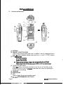
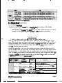
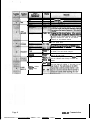
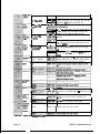
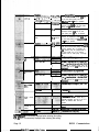
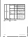
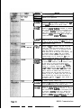
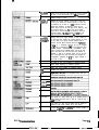
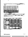
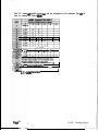
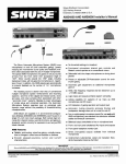
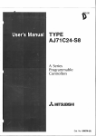
- -
.
.
-
TABLE OF CONTENTS
1 GENERAL lNFORMATlON ....................................................................................................
1 . 1 introduction ..........................................................................................................
1 . 2 Description...........................................................................................................
1.3 Accessories ..........................................................................................................
1.4 License Requirements .........................................................................................
1.5 Technical Assistance ...........................................................................................
1.6 Contmls and lndiirs ........................................................................................
1.7 LCD lcxrns ............................................................................................................
P
2 FIELD (KEYPAD) PiWGRAMMlNG . . . . . . . . . . . . . . . . . . . . . . . . . . . . . . . . . . . . . . . . . . . . . . . . . . . . . . . . . . . . . . . . . . . . . . . . . . . . . . . . . . . . . . .
2.j
Pmgtiming........................................................................................................
Programming Modes .................................................................................
2.1.1
2.1.2
Desk Modes - Quick Reference ..............................................................
2.1.3
Dealer Mode Pragramming ........................................................................
2.1.3.1
Global Settings ...................................................................................
2.1.3.2.
DTMF Settings ..................................................................................
2.1.3.3
Enhanced Global Settings ................................................................
Channel Settings ..............................................................................
2.1.3.4
2.1.4 Cloning ....................................................................................................
2.1.4.1
wired Cloning...................................................................................
Wireless Cloning ..............................................................................
2.1.4.2
2.1.5
Programming by Computer......................................................................
RELM Communications
1
:
1
1
:
3
5
x
6
7
7
::
97
23
fX
24
.
1 GENERAL INFORMATION
1 .I IntmductIon
This manual contains information about field programming through the keypad of the RELM
Wireless RP99APlus series handheld VHF and UHF radiis. This manual is intended for use by
experienced techn’tins familiar with similar types ofmmerdal grade communications
equipment. It contains service information and data for the equipment.
The following precautions are recommended for personal safety:
l
DO NOT transmit until all RF connectors are secure and properly terminated.
l
SHUT OFF and DO NOT operate this equipment near elect&al blasting caps or in an
explosive atmosphere.
l
Only qualified technicians should maintain this equipment.
1 . 2 Ww@tion
The RlWAPlus series radiis are self-contaii VHF or UHF FM Radiis covering the
frequency range of 148MHr to 174MHz for VHF and 45OMHz to 47OMHz for UHF. The radios
am multi-channel and digitally synthesized using a single aystal for frequency control. The
RPg9APlus series incorporate an EEPROM for the storaga of channel frequency, CTCSS
Tone, DCS Code, Two-Tone, and Dual Tone Multiple Frequency/Automatic Numeric Identifier
(DTMFIANI) encode information. The RPBAPlus sertes also include low-battery and busychannei indii.Soft key switches can be programmed to control channel scan,DTMF store
and send, mpeater talk-around, and hi transmit power, various display modes, adding and
deleting channels from the scan list, key lock, and more. Status and channel information is
displayed over an alphanumertc liquid crystal display (LCD). Connectors am provided on the
side of the unit for an external antenna, microphone, speaker, and other optional accessories.
A wida vartety of optional accessories are available for the RP hand held radii. Contact your
RELM Wireless dealer for complete information.
1.4 License Requirmfmts
This equipment must be licensed by the Federal Communications Commission (FCC) before it
may be used. Your RELM Wireless dealer can assist you in filing the appropriate application
for the FCC, and will program each radio with your authorized frequencies and signaling
codes.
1 .J
Teohnkal Assistance
If you need technical assistance, contact a RELM Communications sewice technician:
RELM Wides8 Corporation
AlTNtCustomer~ce
7100 Technology Drive
west Molboume, FL 32904
Phone: (800) 422-8281
FAX: (321) 862-7988
RELM Communications
Page1
Email: [email protected]
1.8
Controls and Indicators
-v
11
13
-
12
i
I
(1) ANTENNA
(2) CHANNEL SELECTOR KNOB
Used to select channel and squelch level. In addition, it can be programmed by the
dealer to delete undesired channels from scan list or to select a CTCSS frequency.
(3) LED INDtCATOR
. lsredwhentl-tmmi~g
. lsgltzellwften~
0
.
Fzasbcs~w~~t#lttcryvoltageislowandapproachingthe~~point
Flashesorangewhenthefadio rec&vespropcrDTMForTwoTonedecodegignais
(4) ON-OFF/VOLUME KNOB
Rotate the volume control knob clockwise to turn the unit ‘on” and fully counter
clockwise to turn the unit ‘off. lkrease or decrease the volume by adjusting the
volume control accordingly.
(5) SPEAKER
(8) MICROPHONE
(7) LCD
Used to display channel and operation status.
(8) (o,o,w,o) PROGRAMMABLE SOFT KEYS
Page 2
RELM Communications
Used to enable or disable auxiliary functions. Press each key to enable its
corresponding function.
Used to enter, store, or send DTMF codes.
(1O)PTT BUTTON
Used to switch between transmit and receive mode.
(1l)iAMP BUTTON,
Used to turn “on” or ‘off the LCD backliiht. Press the [LAM4 button, the backlight will
Wminete for about 5 seconds and then automatically turn off. During illuminating and
pressing any key, except the [LAMP] button, the timer will re-start. To turn “off the
backliiht, press the [LAMP] button again.
(12)MONI BUTTON
Used to monitor the selected channels.
(13)EXTERNAL SPEAKER-MICROPHONE JACK
Used to connect with external the speaker-microphone, programming cable, or cloning
cable.
(14)BELT CUP
(1J)BATTERY
(16)BAmRY LATCH
1.7 LCD kons
II
0 Displays the selected channel number, channel frequency, channel Iabe& squelch level or DTMF
#de. When selective call is enabled, messages received are also displayed here.
Nofir:The”softkeyo”canbsproorammed6otogglebetweendisptaymodes.
Channel Number- Displays channel number. Factory default
channel Frequency- Displays the channel frequency.
Channel Lab& Displays characters of the channel label. Up to 16 alphanumeric characters can
be programmed. Any label over 8 charactars will scroll across the display.
Q Appears when “low’ power is selected.
Q Appe8rs when the selected channel is busy.
RELM Communhtions
Page 3
@I Appears when the [MONI] button is pressed to disable CTCSS, COCSS, OTMF, or Z-Tone.
Q Appears when the [MONI] button is pressed to switch the speaker on.
@ Appears when the selected channel is in the scan list. The radio only scans channels in the
scan list.
@ Appears while in the numeric entry mode when entering the channel labels through the
keypad.
Q Appears in scan mode.
@ Appears when the keypad lock is “on”.
Page 4
RELM Communications
2 FIELD (KEYPAD) PROGRAMMING
21 Programming
You can program the RP99A Plus series in four different ways.
A. Using the unit’s keypad. See section 2.1.2.
B. Cloning from unit to unit using a CCRP ck)ning cable. See section 2.1.2.5.1.
C. Wireless cloning from unit to unit. See section 2.1.2.5.2.
D. With a computer, RESRPM programming software, and a PCRP programming
interface cable. Contact RELM Communications for the software and cable. See
SBcbion 2.15
21.1 P~ramming Modes
Using the unit’s keypad, soft keys, and control knobs, the unit can be placed into one of
several diierertt programming modes. It is important to not& that only RELM authorized
dealers with qualified technicians am allowed to operate the RPV99Plus series radios in the
pf0gramming
mode and to change any programming content. Fiium 2.1 shows the dierent programming
odes.
1
UserMode
1
~.~.~.~.~.~.~.~.~.~.““““-“‘-“‘-“’~.~.~.,
Global
Settinas
I I]
i
i
DTMF Settings
i
jt i
Enhanced Global
e i
1 3 ;
Channel Settings
-._.-.-.-._.---.-~-.-.-.-.-.-.-.-.-.-.-.-.-.-~ S!
I
wiredCloning
Wireless
Factory Mode
Cloning
All Reset
I
1
I
All Sesment DisDlav Test
Test Mode
Band Set
I
Frequency Scan
I
AlianmentSettinos
I
f--EizJ
Figure 2.1 - Programming Modes
RELM Commani43tions
Page 5
Table 2.1 shows the functions that can be sat for each of the “Dealer Modes”. The dealer sets
the operations functions, channel frequencies, signal modes in accordance to the customer’s
neads. The ‘Dealer Mode” must be enabled “ON” in the radio by theRESRPWWs editing
software before the dealer programming mode can be accessed.
1. Monitor 2. Scan 3. Dial 4. Talk Around 5. Low power 8.
Priority I.priority
Channel 8. Look Back A 0. Look Back B 10. Revert Channel 11 .TX Scan Delay
Time 12. Dropout Delay Time 13.Time Out Timer 14. Transmit Waning 15.
TOT Resume Time 18. TOT Reset Time 17. Squelch Level 18. Beep
IQSignalling 20. Battery Save 21. Selectable CTCSS 22. Delete/Add Enable 2 3 .
24. Digit Time 25. Inter Digit Time 26. Fir& 1
Time Wii CTCSS 20. PTT ID 30. Dial ID 31. Connect ID 32. Disconnect ID 33.
No. Gf DTMF Keys 34. DTMF Hold Time 35. Store 8 Send 38.D Key
Assignment 37, DTMF Signaling 38. Intermediate Code 30. Group Code 40. SQ.
~q&@“p?&M~;
UI,: .,,. , i , ,
~~~~~~~:~L~-~~~~~~~
~:“-~~;:~~;~:
45.
Tone
48.
Tone Duration 47. Channel Label Size 48. Soft Key 1
[a] &signm& Group 40. Sofl Group Key 2 [o]Assignment 50. Soff Key 3 [a] Assignment 51.
Y~~~t.$ ,‘ :l r, ,,::
I. Channel Selection 2. RX Frequency 3. RX Tone Signaling 4. TX Frequency 5.
TX Tone Signaling 8. DTMF&Tone Signaling 7. ANI ID Enable 8.Scan
DeleteIAdd 0. Busy Channel Lockout IO. Clock Frequency Shift 11 .TX Power 12.
&n&i&h 13. DTMF ID -de/RX Z-Tone 14. TX Z-Tone 15. Channel La&j1
%&wz~~~;~~~
M !pi;+
@Q;
#&&
~~~~~
&*.\ <, “ , Y l #I,‘_
;r~~~3&v.,~
:ii+&&,~**
1 In this mode. data is cooied from one radio to another throuoh a cable.
ln this mode, data is copied from one radio to another without cable by means
InAne
Table 2.1 - Dealer M=,-
2.1.2 Dealer Ydes - Quick Referwtce
Place the unit in the programming mode by pressing and holding the [LAMP] and [ 0 J buttons,
switch the power “on”. After 2 seconds the radio enters the dealer mode and “SEL” appears on
[ZE:]
the display.
While in dealer mode, press the respective soft function key for the mode to be programmed.
See Table 2.2.
Page 6
RELM Communications
-
--
- _-
-
.
Table 2.2 - Dealer Modes Quick Reference
2.1.3 Dealer Mods Programming
2.1.3.1 Global Settings
To place the unit
into the “Dealer Mode” for adiing tha global settings, do the following:
1. While pressing and hilding the [lAMPI and [ 0] buttons, switch the power ‘on“. After 2
seconds the radio enters the dealer moda and “SEC” appears on the display.
[ S E - : ]
--.
2. While in dealer mode, press [o] to enter the Global Settings mode.
Table 2.3 shows the function number and function options that can be selected while in this
.
mode. While in this mode, the Channel Selector knob is used to set functions “ON” or “OFF” or
to select the setting. After a function is sat, pressing the [PlTl button stores the setting and
increments the menu to the next function option. Also, when the [PlTj button is pushed, a
beep will sound to confirm the setting.
Pressing the [o] button at any time while reviewing the function options will pause the unit to
exit the selection mode and revert back to the dealer mode screen. The current function option
will not be stored if it was changed. After the complete option list has been cycled through,
“End” will appear on the display. To exit dealer mode, cycle the power “off’ and then back ‘ona.
To review or confinn the function settings while in the Global Settings
mode, press and hold
the [MONI]buttun and turn thechannelelect knob.
Disables the [MONI] button.
Monitor Momentary
MONITOR
WI”,
II,“,
L-n
RI”,.,
.,
REZM Communicutions
Signaling squelch (CTCSS, CDCSS, 2-Tone, or
DTMF) is temporarily disabled when the MONI
button is pressed.
Toggles between signal squelch and monitor
1when the [MONI] button is momentarily pressed.
Il;Uii: :.j, $ ‘:. ‘j Unsquelches the receiver while the [MONI] button
~. It=?: ,: ” 7’ ; ,I is wessed.
“:
:/,
,,
,,
1%
&
:
1SCAN OFF 1Dircables
SCAN
mode.
Page?
;
Disable
Disable
1-99
SCAN TO ‘Time Operated’ SCAN.
DIAL OFF Disables the fDlAL1 kev.
the same as the receive frequency and the receive
frequency becomes the same as the transmit
1 frequency of the selected channel.
LO OFF 1 Disables the [LO] button so the user cannot select
the low power mode.
LO.~:::Cjj$::’ Enables the [LO] button so the user can toggle
+Y.:T.
.,‘s: :la,~t(,&:
the 1~ and high transmit p-r mod=.
iY Q’& :.“~~&~;
d;‘r~ mn
,
PRlO.:-CFF
Disables the Priority feature.
The Priority channel is a fixed channel selected by
PRIO FIX
the dealer. The user cannot change it.
The priority channel can be selected by the user
PRIO SEL
while in the user mode.
~RICJ$&,!I~~V,
The fixed priority channel number. Note: “Fixed”
must be selected under Priority to enable this
PRlCH gg feature.
LBA
3oo Conditions: 1. The priority feature is enabled. 2.
,
The Scan feature is enabled. 3. The radio is in the
3flOms - 1500ms
:lOOms steps)
Page 8
RIZLM
Communications
t
LBB 500
LBB 5000
Last used
Selected * Talk Back
Priority
Priority + Talk Back
D.58 - 5.0s
(0.5s steps)
D.5s q 5.0s
[Oss steps)
RELM Communications
Conditions: 1. The priority feature is enabled. 2.
The Scan feature is enabled. 3. The radio is in the
scan mode. 4. The radio stops on an active
channel that is not the priority channel. 5. A signal
is detected on the priority channel, but the
signaling squelch (CTCSS, CDCSS, ~-TOM?, or
DTMF) is not the same as the priority channel.
Look Back B is the time intervals that the priority
is checked for activity while receiving on the nonpriority channel.
Starts scanning or resumes scanning from the
selected channel. When scanning and the PlT
button is pressed, it will transmit on the last
REV SEL
channel to be selected by the channel selector
even if a call is being received on another
channel.
Starts scanning or resumes scanning from the last
channel that received a call. When scanning and
the PTT button is pressed, it will transmit on the
last channel that received a call.
Starts scanning or resumes scanning from the last
channel that was transmitted on. When scanning
REV LSTU and the PlT button is pressed, it will transmit on
the last channel that was transmitted on even if a
call is being received on another channel.
Starts scanning or resumes scan from the
selected channel. When scanning and the PTT
button is pressed, it will transmit on the last
channel to be selected by the channel selector; or
SEL TALK if a call is received and the Pll’ button is pressed,
it will transmit on the received channel (the PlT
must be pressed before the Drop Out Delay Time
ends, othewise it will transmit on the last channel
selected).
Starts scanning or resumes scanning from the
priority channel. When scanning and the PlT
REV PRIO button is pressed, it will only transmit on the
priority channel. When in the manual mode, the
radio will transmit on the selected channel.
Starts scanning or resumes scanning from the
priority channel. When scanning and the PTT
button is pressed, it will transmit on the priority
channel; or if a call is received on a non-priority
PRI TALK
channel and the PTT button is pressed, it will
transmit on the received channel (the PTT must
be pressed before the Drop Out Delay Time ends,
otherwise it will transmit on the priority channel).
TSDT 0.5 The period of time that the radio stays on a
+f@m! i,,&W channel after a transmission has been made
TSDT 5.0 before it resumes scanning.
DODT 0.5 The period of time before the radio resumes
$JQppJfg ? scanning after a received channel becomes
DODT 5.0 inactive.
Page 9
TOT OFF
OFF 3Os-300s
(30s steps)
TOT 30
TOT. .60
3~ TOT,I 300
_,
The period of time that a user can transmit before
it stops transmitting. The unit beeps until the user
releases the PlT button to reset the TOT.
.
OFF is-60s
(1s steps)
;‘.;.
‘L’i:. ,..,
1TCTA
OFF IS-SOS
(1s steps)
OFF 1~45s
(WlSTRP)
7;:
1
j The oeriod of time that a user can transmit before
it starts beeping. The unit beeps until the user
releases the PTT button to reset the timer.
-I--
TOTA 60
,‘..:‘~~~,~~:;.,
, ~,~,.‘!~“:8,1;-:$+
;,
,’
,TQTKzF Disabled
‘.: , , . i;. , i, ;
After the TOT period, this is the period of time the
radio must be in the receive mode before the PTT
TOTK 60
button is active.
,I.
.‘. - , . , . , ..i: I ;’ Disabled -The PIT button can be pressed
1 T6’%-6FF:
1 immediately after released upon TX TOT timing
j.. ,“, vi_
TOT;(““’ l’
1
‘-“.,~~~~~~~~~‘~.~:~.
::‘:;, 1’ od
TOTS
1
TOTS 15
j After the TOT DeriOd. this is the period of time the
radio must be &r-keyed before the PlT button is
acttve.
o-o
Squelch level adjustment - Zero is minimum
squelch adjust and 0 is maximum squelch adjust.
(1 step increment)
No beeps will be heard when the keypad is
:~~~?~~~~~~~~~,~~~~~-~:~~~~o
; ,#&Z;,,l:
j :z&.!p>~
jl
,:, >.i. .A<, ., ,, _, >,
Enables the user to toggle through all CTCSS
tones when on a specific channel - affects RX and
.:*,.‘ ,.. : :.:$ :.’
Disabled. Prohibii the user to add or delete
channels to or from the list of channels to be
scanned.
Pennits the user to add or delete channels to or
from the list of channels to be scanned.
Disable
Disable
I
I
I
MODE OFF Prohibii Dealer and Test modes
moDal semngs
Page 10
RELM Communications
2.1.3.2. DTMF Settings
To place the unit into the ‘Dealer Mode’ for ediing the DTMF settings, do the following:
1. While pressing and holding the (LAMP] and [O] buttons, switch the power “on”. After 2
[x-j
seconds the radio enters the dealer mode and “SEL” appears on the display.
2 . While in dealer mode, press [O] to enter the DTMF Settings mode.
Table 2.4 shows the function number and function options that can be selected while in this
mode. while in this mode, the Channel Selector knob and keypad (O-9, *, #, A-D) are used to
set DTMF functions ‘ON” or MOFF or to select the setting. After a function is set, pressing the
[PTTJ’ button stores the setting and increments the menu to the next function option. Also,
whsn the [purl button is pushed, a beep will sound to confirm the setting.
Pressing the [O] button at any time while reviewing the function options will cause the unit to
exit the sektlon mode and revert back to the dealer mode screen. The current function option
will not be stored lf it was changed. After tha completa option list has been cycled through,
“W will appear on the display. To exit dealer mode, cycle the power =or and than back “on”.
-.
To review or confirm the function settings while in the DTMF Settings mode, press and hold the
[MONI] button and turn the channel select knob.
(1 Oms steps)
I
I
5Oms
- 200ms
1OOms-1OOOms
(!5Oms steps)
100ms4000ms
(50ms steps)
1 ICW ‘.i:. 50
RISE 100
‘RISE M“.
RISE 1000
RTQT 100
T$liQT$ :$fj&
RTQT 1000
_-
The period of time that each of the
programmed DTMF ANI digits are
transmitted.
The period of time between each of the
programmed DTMF ANI digits
The period of time that the first digit of
the programmed DTMF ANI is
transmitted.
~The period of time between un~modulated TX carrier and when the
~ programmed DTMF ANI is transmitted.
~The period of time between unmodulated TX carrier and when the
oroorammed
CTCSS is transmitted.
]. Except for functions 31 and 32 that am set with the keypad.
L When DTMF function is enabled together with the Battery Save mode, and when CTCSS is used, the
transmit delay time should be set * 300 ms.
REZM
Communications
Page 11
DIAL ID
~D&!!bMq
z +&;
When transmitting, the programmed
,‘. , ,.: , . .*y
.irl. . i. .‘:id. ’-. i”‘i:e
+!
: ,:‘.: ,. .,. : . , : t p,&&_4$F..I~
1,
’ ‘+’ Connect or Disconnect DTMF ANI will
;
i
.,.
.,-’
: ” ] ~.&~“~
be sent when [DIAL] and the
, ,:, .- ‘i not
;,,;ip’ :::;,* i k.... . ..,
pt;:p ,q ,:..;
. , . ,: ;1!‘#/ ,,, ‘i’! :I.‘ - $. , . q&-p
res ective .~
z,‘,., <, ,;. s;.-:wl .kb; ;, T” ” “: I’$@!
or ‘f key is pressed.
_:‘i
. ,-( : .’
P.IDBEGIN
When transmitting, the programmed
Connect
Connect DTMF ANI will be sent when
[DIAL] and ‘* key is pressed.
When transmitting, the programmed
P.ID END
Disconnect
Disconnect DTMF ANI will be sent
when [DIAL] and ‘#” key is pressed.
When transmitting, the programmed
Connect or Disconnect DTMF ANI will
Both
P.ID BOTH
be sent when [DIAL] and respective ‘*
or ‘f key is pressed.
-,Di#?fe I:!; i.;i,? . : : , ,+ z:..;Rt ~&1D:&lFF:~~~ Disabled
1 D.ID ON
When transmitting, a stored DTMF ANI
ON
code will be sent when [DIAL] and a
memory location key is pushed. An
ANI number must be programmed in
the user mode. Up to 10 memory
locations can be used (keys 0 through
CONNECT
ID3
I
and SC key is pressed. Note: Only the
last five digits of the ANI number will be
and ‘+ key is pressed. Note: Oniy thelast five digits of the ANI number will be
D)
Disable
DHT OFF
C, D, l and #.
No Hold Time
~, r 2 seconds after
the last number on the DTMF key is
manually selected, but only if the PTT
button is released after the last
number.
Does not allow Auto ID numbers to be
DTMF HOLD
TIME
STORE 8
SEND
3 ‘PJDBEGIN’ is momentarily displayed when entering this setting.
4 ‘P.ID END” is momentarily displayed when entering this setting.
RELM Communications
Page 12
--. -.- .-.-
___--
-
--
DKEYA 1
DKEYA 16
DTMF OFF
DTMF CSQ
DTMF
SIGNAL .ING
DTMF SEL
O-9
A-D
MC 0
MC 9
IMC A
IMC D
IMC E
fMB” F 7,. ,: :I
1A - D
@if? qp
GRPC A
GRPC D
GRPC E
When transmitting, the radio transmits
an w-modulated signal for the
programmed time when [DIAL] and the
D key is pressed.
Disabled
When the respective DTMF code is
received on a channel, the radio will
ring for approximately 10 seconds and
receiver audio will open. The ringing
can be terminated by the user
responding with a transmission or by
pressing the MONI button.
Conditions: 1. The receiving radio must
have a three digit DTMF ID Code
programmed. 2. The transmitting radio
must be programmed with a 3-digit
DTMF ID code, a ldigit Intermediate
Code, and a I-5 digit Message code.
(i.e. 123 # 4567). The whole
message string is sent when the [DIAL]
key is pressed.
The digit that separates the 3 digit
DTMF ANI code to be decode and the 1
to 5 digit message (Ex. 123 # 4567)
Disabled
Identifies that a DTMF Select call is for
a group, not for an individual.
GRPC F
OFF
Is - 15s
(1s steps)
40 OFF
SART 1
SART 10
SART 15
Disabled
After a DTMF signal is decoded, it is
the period of time before the squelch is
reset to the ready state of decoding
another DTMF signal.
5 When changing and storing a ‘DTMF SIGNALING” option, the ID CODE setting in channel mode will be
met to 7XW; and the 2-Tone settings will be reset to V”.
RELM Communications
Page 13
/
J
Disabled
Call Alert
CAT OFF ’ _
CAT RING
CAT BEEP
TRANSPOND
Alert).
CALL
ALERT/
TRANSPOND
(Call
TRANSPOND (ID
code)
CAT CALT
CAT IDCD
TRANSPOND
(Transpond Code)
CAT TRCD
Disabled
The radio flashes the LED indicator and
rings when it decodes a two-tone or
DTMF signal.
The radio flashes the LED indicator and
beeps when it decodes a two-tone or
DTMF signal.
The radio flashes the LED indicator and
rings when it decodes a two-tone or
DTMF signal; and it transmits the alert
back to the sending radio.
The radio llashes the LED indicator
when it decodes a two-tone or DTMF
signal. If DTMF is used, the receiving
radio also transmits the DTMF ID code
(listed in the Channel programming)
back to the sending radio.
The radio flashes the LED indicator
when It decodes a two-tone or DTMF
signal. If DTMF is used, the receiving
radio also transmits the DTMF ID code
(listed In the DTMF Auto ID that is
stored in location 0) back to the
sending radio. If no DTMF Auto ID is
stored in location 0, the receiving radio
will not transpond.
-able 2.4 - Dealer Modr ~TMF Settings
If any of the functions in Table 2.3 and Table 2.4 are set to “Off”, the related setting shown in
taMi 2.5 can be set, but tha setting will not be recognized.
Page 14
RELM Communications
-.
_
--
&&&$:,
‘;.>
‘2;.
)?
,’
TO
::
&&@&
d#@$
_,
37. DTMF sianalina is OFF
DTMF
2. [SCN]
;
I 7. Prioritv is fixed or selected.
Fiied, Selected
I
2. [SCN] is OFF
6. Priority is OFF or fixed.
6. Priority is OFF
6. Priority is OFF
19. Look Back B
1 10. Revert CH
Priority, Priority + Selected
6. Priority is OFF
Il. Dwell Time
12.lSCNl is OFF
I
12. Dropout Delay Time
12. fSCN1 is OFF
14. TOT Pm-Alert
I
I
I
I
I
15. TOT Rekey Time
16. TOT Reset Time 31. Connect ID
1 32. Disconnect ID
13. Time Out Time is OFF
13. Time Out Time is OFF
13. Time Out Time is OFF
29. PlT ID is OFF or disconnected and 30. Dial ID is
1OFF
129. PTT ID is OFF or connected and 30. Dial ID is
37. DTMF signaling is OFF or is code SQ.
37. DTMF signaling is OFF.
37. DTMF signaling is OFF.
Tabfe 2.6 - Disabled Function Conditions
2.1.3.3 Enhanced Global Wings
To place the unit into the “Deafer Mode” for editing the enhanced globa! settings, do the
following:
1. While pressing and holding the (LAMP] and [O] buttons, switch the power %n”. After 2
seconds the radio enters the dealer mode and “SEL” appears on the display.
2 . While in dealer mode, press [a] to enter the Enhanced Global Settings mode.
Table 2.6 shows the function options that can be selected while in this mode. While in this
mode, the Channel Selector knob is used to set functions “ON” or ‘OFF” or to select the
setting. After a function is set, pressing the [PTTI button stores the setting and increments the
menu to the next function option. Also, when the [PllJ button is pushed, a beep will sound to
confirm the setting.
Pressing the [o] button at any time while reviewing the function options will cause the unit to
exit the selection mode and revert back to the dealer mode screen. The current function option
will not be stored if it was changed. After the complete option list has been cycled through,
“End” will appear on the display. To exit dealer mode, cycle the power “off’ and then back ‘on”.
RELM Communications
Page 15
TO rev@w or confirm the fun&on settings while in the Enhanced Global Set mode, press and
hold the [MON1] button and turn the channel select knob.
Dliiplpy
-‘, _,. .l’...“‘: : :,fWitark ‘,;Js,;,ll .,cc’, i,. i .$‘ y,:; Tii i;; :, j< ~: ,;~;,c>;I;,;:;’ .,!, .,. : ,: r (_ _’ ‘,: 1 ;, .b, ; /
:.‘;, .<,;;y.+.: ;‘$i;:i “::*‘-,:” . ,:; .$ :+:.r ,. ,; .: ;, ,,,. : :
+’ C,‘:. -:GRPT OFF
GRPT A
GRPT B
0.5 - 10s
(0.1s steps)
GTDUR 0.5
Off,l-16
(1 step)
Group Tone set to “OFF
Group code set to the ‘A’ Tone.
Group code set to the ‘B” Tone.
Group Tone duration.
GTDUR 10.0
SIZE OFF
The channel label display mode is disabled.
SIZE 1
The number of channel label characters that
can be displayed.
SIZE 16
No Function
Scan
Dial
Talk Mound
Law PoweJr
Display Label
y Frequency
Kl OFF
Kl SCAN
Kl DIAL
Kl TARE
Kl
1 Kl
1 Kl
._ -_Lo
,
Variable C3-r.
SQL
No Function
Scan
Dial
Talk Around
Low Power
Display Label
Displa y Frequency
Display Mode
Scan Add/Del
Key Lock
Variahla i
1 -,.-w.- 41
SQL
No Function
._-.
-..- _._..
Scan
Dial
Talk Around
Low Power
Display Label
Display Frequency
Display Mode
Scan Add/Del
Kev Lock
Variable C3-r
.
SQL
No Function
Scan
Page 16
The function key is disabled.
The function selected will be assigned to this
soft key.
.I.
1 Kl
. . . VQT
Kl SQL
K2 OFF
K2 SCAN
KZDIAL .
K2 TARE
1 K2LO
IK2 DCHAR
IK2 DFREQ
KZDMODE
KZSADD
K’ KLOCK
VQT
iQL
.-K3CIFF
K3 SCAN
K3 DiAL
K3TARE
K3 LO
1K3 DCHAR
Ir( (3 DFREQ
I K3DMODE
1 K3SADD
,1K.?
a.” KLOCK
t KR
. ._ VQT
K3 SQL
K4 OFF
K4 SCAN
The function key is disabled.
The function selected will be assigned to this
soft key.
The function key is disabled.
The function seiected will be assigned to this
soft key.
The function key is disabled.
The function selected will be assigned to this
RELM Communications
l’abk 2.6 - Dealer Mods Enhanced Global Settings
2.1.3.4 Channel Settings
70 place the unit into the “Dealer McxW’ for editing the channel settings, do the following:
1. while pressing and holding the [LAMP] and [O] buttons, switch the power “on’. After 2
seconds the radio enters the dealer mode and %EL” appears on the display.
2. While in dealer mode, press [m] to enter the Channel Setting mode.
Table 2.7 shows the fUnction options that can be selected while in this mode. While in this
mode, the Channel Sekctor knob is used to set functions “ON“ or “OFF” or to select the
setting. After a function is set, pressing the [Pm button stores the setting and increments the
menu to the next function option. Also, when the [PTTJ button is pushed, a beep will sound to
confirm the setting.
Prassing the [a] button at any time while reviewing the function options will cause the unit to
exit the selection mode and revert back to the dealer mode screen. The current function option
will not be s&red if it was changed. After the complete option list has been cyded through,
‘End” will appear on tha display, To exit dealer mode, cyde the power ‘off” and then back *on”.
RELM Commnnicatiaas
Page 17
-
Channel to be programmed.
No receive or transmit frequency
160.06600.
100.00@~.
100.00~
16~.00000
OFF
QT 61.0
Q T 67.1”
DQTBN
DQTO23]
DQTWN’
Pressing the [o] button toggles no frequency to the start
of the reoeive frequency if the channel is blank
Rotating the channel selector will raise or lower the
frequency by 2.5kl-i~ or 6.25KHz increments. If a decimal
point is shown next to the last digit of the frequency, then
the increment is 6.25Kl-l~; if there isn’t a decimal point
shown next to the last digit of the frequency, then the
increment is 25KHz. Pressing the [o] key will toggle the
increment size between 2.5kHz and 6.25KHz.
Holding in the lamp key and rotating the channel selector
will raise or lower the frequency by IMHz increments.
Disables CTCSS or DCS
Selecting the [u] key switches it from OFF to the first
CTCSS tone. Rotate the channel selector to move the
tone frequency up or down in 1 Hz increments until the
desired tone frequency is reached. If there isn’t an
asterisk shown next to the last digit of the frequency, then
the increment change is 1Hz; if there is an asterisk
shown next to the last digit of the frequency, then the
increment change Is 0.1 Hz. Pressing the [o] key will
toggle the increment size between 1 Hz and 0.1 Hz.
Selecting the [III] key again switches lt from CTCSS to
the first DCS tone. Rotate the channel selector to move
the DCS code up or down until the desired code is
reached. The last alpha character will be an ‘N” (noninverting) or ‘I” (inverting). Pressing the [O] key toggles
the ‘N’ and ‘I”. Pressing the [o] key will toggle the DCS
selection between ‘standard’ and *non-standard’ DCS
codes. If there isn’t an asterisk shown next to the last
digit of the DCS code, then the DCS tone selection is
‘standard’; if there is an asterisk shown next to the last
digit of the DCS code, then the DCS tone selection is
‘non-standard”. Selecting the [II] key again switches it
from DCS to OFF.
No transmit frequency. Receive only.
l6o.ooooo.
Pressing the [o] button toggles no frequency to the start
of the transmit frequency if the channel is blank
Rotating the channel selector will raise or lower the
frequency by 2.5kl-l~ or 6.25KHz increments. If a decimal
point is shown next to the last digit of the frequency, then
the increment is 6.25Kl-l~; if there isn’t a decimal point
shown next to the last digit of the frequency, then the
increment is 2.5KHz. Pressing the [a] key will toggle the
increment size between 2.5kl-l~ and 6.25Kl-l~.
RELM Communications
--
-
10~.00000
Holding in the lamp key and rotating the channel selector
will raise or lower the frequency by 1 MHz increments.
OFF
Disables CTCSS or DCS
QT 61.0
QT 67.1*
DQT623N
DQTE!
DQTWN’
Selecting the [o] key switches it from OFF to the first
CTCSS tone. Rotate the channel selector to move the
tone frequency up or down in 1 Hz increments until the
desired tone frequency is reached. If there isn’t an
asterisk shown next to the last digit of the frequency, then
the increment change is 1 Hz; if there is an asterisk
shown next to the last digit of the frequency, then the
increment change is O.lHz. Pressing the [o] key will
toggle the increment size between 1 Hz and 0.1 Hz.
Selecting the [o] key again switches it from CTCSS to
the first DCS tone. Rotate the channel selector to move
the DCS code up or down until the desired code is
reached. The last alpha character will be an ‘N’ (noninverting) or ‘I” (inverting). Pressing the [o] key toggles
the ‘N’ and ‘I”. Pressing the [o] key will toggle the DCS
selection between ‘standard’ and “non-standard’ DCS
codes. If there isn’t an asterisk shown next to the last
diglt of the DCS code, then the DCS tone selection is
‘standard”; if there is an asterisk shown next to the last
dlgit of the DCS code, then the DCS tone selection is
‘non-standard”. Selecting the [o] key again switches it
from DCS to OFF.
SIG OFF
No DTMF or Two Tone signaling on selected channel.
SIG DTMF
Allows DTMF signaling on selected channel.
SIG TTS
Allows Two Tone signaling on selected channel.
ANI OFF
Disables this feature.
ANI O N
to be transmitted every time the
SCAN DEL
SCAN ADD
B.C.L.0 OFF
B.C.L.0 ON
SHIFT OFF
SHIFT On
RELM Communkations
TXPWR H
High power is 5 watts. When set to Hi, pressing the [Lo]
button toggles the power from 5 watts to 1 watt or from 1
watt to 5 watts.
TXPWR L
Low power is 1 watt. The [Lo] button will not toggle the
channel to high power. Always set to low power.
WIDE
Receiver bandwk#h
less than +/SKHz.
is +I-25KHz
and transmit deviation is
Page 19
eceiver bandwidth is +I-12.5KHz
is less than +I-2.5Kl-L
and transmit deviation
‘ID’ will flash one time if DTMF signaling has been
selected. The DTMF code must have a minimum of 3
digits, but no more than 10 digits. If more than 8 digits
are used, the display will scroll.
r
A tone from 280 Hz to 3500 Hz in 1 Hz increments can
be used for 2-Tone signaling. The tone sets in the TTS
table (I-16 tone sets) can be edited by using the PC
editor (RESRPQQPlus) and PC cable (PCRP). If no
change has been made to the TTS table, then only
defaults can be selected from Table 2.10.
TTs_R 18
lTS_T 1
I
A tone from 280 Hz to 3500 Hz in 1 Hz increments can
be used for 2-Tone signaling. The tone sets in the TTS
table (l-16 tone sets) can be edited by using the PC
editor (RESRPQQPIus) and PC cable (PCRP). If no
chenae
-..-..~- has
-~- been
~. made to the TTS table. then onlv
defaults can be selected from Table 2.16.
TTS-T 16
#
II uswn s
I\
I
I
‘CH LABEL” will flash once prior to label entry mode. See
Table 2.11 for all the possible characters and character
key assignment.
Table 2.7 - Dealer Mode Channel Settings
Any tone frequency between 67.0 Hz and 250.3 Hz can be programmed into the RP599APlus
Seriesradlos.Huwever, it is recommended to use the standard TIA/EtA403-A CTCSS Tone
Frequencies shown in table 2.8.
Table 2.8 - CTCSS Frequencies
’ DTMF ID Code will not show unless DTMF is selected in step 1 of this section. DTMF and ‘ITS cannot be enabled
simuttaneously. Also, the
’ Two Tone Signaling code will not show unless TTS is selected in step 1 of this section.
Page 20
RELM Communications
-.
Any CDCSS coda between 000 and 777 can be programmed into the RP599APlus Series
radios. However, it is recommended to use the standard TIA/ElA-603-A CDCSS Codes shown
in tab#e 2.9.
-047
051
054
, 065 1
116
125
131
$32
165
172
174
205
261
263
265
271
351
364
365
371
Table 2.9 - Standard TWElA493-A
445
464
465
466
606
612
624
627
712
723
731
732
CDCSS Codes
A tone fmm 260 Hz to 3500 Hz in 1 Hz inctemants can be used for P-Tone signaling. Only the
frequencies in the lTS table can be selected when programming through the front keypad.
The tone sets In the TTS table (l-16 tone sets) can be edited by using the PC editor
(RESRP99Plus) and PC cable (PCRP). If no changes are made to the TTS table, then only
defaults can be selected from Table 2.10.
4#)0
5
D
1141
01
1141
1301
1463
0
7
7
4
456
0.5
0.5
0.5
0.5
0.5
0.5
0.5
0.5
0.5
0.5
0.5
0.5
0.5
0.5
0.5
0.5
0.5
0.5
Inr
i:;
0.5
0.5
0.5
0.5
0.5
0.5
0.5
0.5
0.5
0.5
I
I nr
ii:;
0.5
0.5
0.5
-.
Page 21
Table 2.11 shows 8ll possible char8cters and key assignment to the characters that can be
used for entering the channel label.
1
1or0
i
.
i
1 i =
i 7 i
ts the cursor to the next character location, -+
.”
$f@{ To store and mm&te the m&v.
Used to move the cursor back and forth, +-+
2. Table 2.111 Lat ntl charact8f8
I
I
RELM Communications
Page 22
_-
I
I- -
Cloning allows the memory contents of one unit (source) to be transferred to another unit
(target). There are twu mathods that can be usad for cloning tha RPV5gg sarias radii.
.
l
Wired - Cloning using tha CCRP cloning cable.
Wlmless - Over the air cloning.
21.4.1 Wired Cloning
f. TurntMhthesourc0andtargatunksWV.
2. Connect each end of tha CCRP cable into the respective micmphone jacks of the radii.
3. Turn tha taqet unit ‘on”.
Do the following with the souma radii:
Target Display
source Display
4. While pressing and holding the [LAMP] and
[o] buttons, switch the power “on”. After 2
seconds tha radio enters the dealer mode
and “SEL” appears on the display.
5. Press the [LAMP] button to enter the done
mode. “-c-’ will appear in the display.
6. Press the WONI] button to transmit the
data to the target unit. While the data is
being transferred, the rad LED will light on
the target unit and the busy icon on the
display will flash. When the transfer is
complete. Both displays will show “END”.
7. To done another target unit turn off the target unit, remove the CCRP cable from the
target unit, connect the CCRP to another target unit, and switch the unit on.
8. Press the [LAMP] button on the sourca unit, “SEL” appears on the display.
9. Repeat steps 5 and 6 to done more units.
Target Display
!.1.4.2 Wimless Cloning
Due to the length of the transmission for the transfer, the wireless
doning process is performed with two separate data transfers
(first 0% - 50% and second 50% - 100%)
bo the following with the target radio:
[
CT,
ALL
[-iiiii]
1. Remove the antenna.
1
2. while prassing and holding the [LAMP] and [O] buttons,
switch the power “on”. After 2 seconds the radio enters
the dealer mode and “SEL” appears on the display.
1
RELM Com~uni~tions
1
J
Page 23
3. Pressthc WNI] button to enter the wireless clone mode
A freqw =y will appear in the display. Adjust the channel
b to ac&rst the freqwwy to the desii
i!zlgz to receive data on. Note: Pressing the [LAMP]
buttonwl le turning the channel selectorwillchange the
frequent in 1 MHz steps.
vith the source radii:
4. While pn 38 using and holding the [LAMP] and [o] buttons,
switchtil8 power UonD. After 2 seconds the radio enters
the desk !r mode and “SEL” appears on the display.
5. Press the 31 [MONI] button to enter the wireless clone mode.
A frequel ni=y will appear in the display. Adjust the channel
select kn 01 b to adjust the frequency to the desired
frequent to transmit data on. Note: Pressing the [LAMP]
button WI le turning the channel selector will change the
frequent in 1 MHz steps.
8. Press thr
50%) of 1
of both tl
icon will I
icon will I
indicator
target3 1
During cl
digit at a
PTT button to start cloning the first half (0% e data. ‘00 CLONE” will appear in the displays
t source and target units. Also, the “Lo” power
3 displayed on the source unit and the receiver
B displayed on the target unit. The source’s LED
rill be red (inditing transmitting) and the
ED indicator will be green (indicating receiving).
ning, the two-digit counter will increment one
me on each of the displays.
Source Display
r
1
I iB CL&E
When clonin is successful, “END” will be shown on the displays. If “ERROR” is shown on
the target3 c splay, start the cloning process over. Make sure the batteries are fully
charged and Irn hat the source and target units are in close proximity to each other.
7. Allow the ,transmitter to rest (cool down) for approximately 1 - 3 minutes before starting
the sect01nc 1 half (50% - 100%) of the data transfer.
8. Pressthr 31 [LAMP] button to continue cloning the second half (50% - 100%) of the data.
“50 CL@ JE ?’ will appear in the displays of both the source and target units. Also, the
*Loa pow r icon will be displayed on the souse unit and the receiver icon will be
displayec on the target unit The source’s LED indicator will be red (indicating
transmitti g) and the target’s LED indicator will be green (indicating receiving). During
cloning, 1 e two-digit counter will increment one diiit at a time on each of the displays.
When cloning is wcessful, “END” will be shown on the displays. If ‘ERROR” is shown on the
target’s display, tart the cloning process over. Make sure the batteries are fully charged and
thatthesource~ Id target units are in close proximity to each other.
2.1.5
Program
Programming a
Communicationr
Page 24
-
ning by Computer
ldio from a computer is not covered in this manual. Contact RELM
for the programming cable (PCRP) and software (RESRPW).
RJELM Communications