1
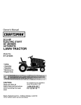
Owner's Manual
£RRFTSMnll°
6.0 HORSEPOWER
22" REAR DISCHARGE
POWER PROPELLED
ROTARY LAWN MOWER
Model No.
917.377830
•
°
°
e
Safety
Assembly
Operation
Maintenance
o
,
EspaSoi
Repair Parts
CAUTION:
Read and follow all
Safety Rules and Instructions
before operating this equipment
Sears, Roebuck and Co., Hoffman Estates, IL 60179
Visit our Craftsman webslte:www,sears,com/craftsman
Warranty
Safety Rules
Assembly
Operation
Maintenance Schedule
Maintenance
2
2
4
6
10
10
Product Specifications
Service and Adjustments
Storage
Troubleshooting
Repair Parts
Parts Orderin,
11
14
16
t7
37
Back Cover
LIMITED TWO YEAR WARRANTY ON CRAFTSMAN POWER MOWER
For two years from date of purchase, when this Craftsman Lawn Mower is maintained,
lubricated, and tuned up according to the operating and maintenance instructions in
the owner's manual, Sears will repair free of charge any defect in material or workmanship,
If this Craftsman Lawn Mower is used for commercial or rental purposes, this warranty
applies for only 90 days from the date of purchase.
This Warranty does not cover:
• Expendable items which become worn during normat use, such as rotary mower
blades, blade adapters, belts, air cleaners and spark plug.
, Repairs necessary because of operator abuse or negligence, including bent
crankshafts and the failure to maintain the equipment according to the instructions
contained in the owner's manual.
Warranty service is available by returning the Craftsman power mower to the nearest
Sears Service Center/Department in the United States. This warranty applies only
while thts product is in use in the United States.
This Warranty gives you specific legal rights, and you may also have other rights which
vary from state to state.
SEARS, ROEBUCKAND CO., D/817 WA, HOFFMAN ESTATES, ILLINOIS 60179
Safety standard's requ!re.operator
presence controls to rntm_mlze the risk of
injury. Your unit is equipped with such
controls. Do not attempt to defeat the
function of the operator presence controls
under any circumstances.
° Do not operate mower if it has been
dropped or damaged in any manner.
Always have damage repaired before
using your mower.
o Do not use accessory attachments that
are not recommended by the manufacturer° Use of such attachments may be
hazardous.
o The blade turns when the engine is
running.
TRAINING:
• Read this operator's manual carefully.
Become familiar with the controls and
know how to operate your mower
properly. Learn how to quickly stop
mower.
° Do not allow children to use your
mower. Never allow adults to use mower
without proper instructions.
° Keep the area of operation clear of all
persons, especially small children and
pete.
• Use mower only as the manufacturer
Intended and as described in this
manual.
PREPARATION:
° Always thoroughly check the area to be
mowed and clear it of all stones, sticks,
wires, bones, and other foreign objects.
These objects will be thrown by the
blade and can cause severe Injury,
° AIways wear safety glasses or eye
shfelds when starting and while using
your mower.
2
o Dress properly. Do not operate mower
when barefoot or wearing open sandals.
Wear only solid shoes with good traction
when mowlng.
- Check fuel tank before starting engine.
Do not fill gas tank indoors, when the
engine is running or when the engine is
hot. Allow the engine to cool for severaf
minutes before filling the gas tank.
Clean off any spilled gasoline before
starting the engine.
o Always make wheel height adjustments
before starting your mower. Never
attempt to do this while the engine is
running_
• Mow only in daylight or good artificial
light.
OPERATION=
• Keep your eyes and mind on your
mower and the area being cuL Do not
let other interests distract you°
- Do not mow wet or slippery grass, Never
run while operating your mower. Always
be sure of your footing - keep a firm hold
on the handles and walk.
o Do not put hands or feet near or under
rotating parts. Keep clear of the discharge opening at all times.
° Always stop the engine whenever you
leave or are not using your mower, or
before crossing driveways, walks, roads,
and any gravel-covered areas.
• Never direct discharge of material
toward bystanders nor allow anyone
near the mower while you are operating
lto
o Before cleaning, inspecting, or repairing
your mower, stop the engine and make
absolutely sure the blade and all
moving parts have stopped_ Then
disconnect the spark plug wire and keep
it away from the spark plug to prevent
accidental starting.
• Do not continue to run your mower if you
hit a foreign object. Follow the procedure outlined above, then repair any
damage before restarting and operating
your mower.
• Do not change the govemor settings or
overspeed the engine. Engine damage
or personal injury may result.
, Do not operate your mower if it vibrates
abnormally, Excessive vibration is an
indicalion of damage; stop the engine,
safely check for the cause of vibration
and repair as required.
o Do not run the engine indoors° Exhaust
fumes are dangerous.
• Never cut grass by pulling the mower
towards you_ Mow across the face of
slopes, never up and down or you might
lose your footing. Do not mow excessively steep slopes. Use caution when
operating the mower on uneven terrain
or when changing directions - maintain
good footing.
• Never operate your mower without
proper guards, plates, grass catcher or
other safety devices in place.
MAINTENANCE AND STORAGE:
° Check the blade and the engine
mounting bolts often to be sure they are
tightened properly.
o Check all bolts, nuts and screws at
frequent intervals for proper tightness to
be sure mower is in safe working
condition.
o Keep all safety devices in place and
working,
• To reduce fire hazard, keep the engine
free of grass, leaves or excessive
grease and oil.
. Check grass catcher often for deterioration and wear and replace worn bags.
Use only replacement bags that are
recommended by and comply with
specifications of the manufacturer of
your mower.
° Always keep a sharp blade on your
mower.
° Allow engine to cool before storing in
any enclosure.
,, Never store mower with fuel in the tank
inside a building where fumes may
reach an open flame or an ignition
source such as a hot water heater,
heater,
CAUTION.
Always
p_gpaCe
clothes disconnect
dryer, etc. spark
wire and place wire where it cannot
contact spark plug in order to prevent
accidental starting when setting up,
transporting, adjusting or making repairs.
WAR,NING
engine exhaust from this product
contains chemicals known to the State of
California to cause cancer, birth defects, or
other reproductive harm.
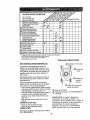
Theseaccessorieswereavailablewhenthislawnmowerwasproduced.They arenot
shippedwith your mower. They are also available at most Sears retail outlets and se_ce
centers. Most Sears stores can also order repair parts for you, when you provide the model
number of your lawn mower_ Some of these accessories may not apply to your lawn mower.
LAWN MOWER PERFORMANCE
,,.J_
CLIPPING DEFLECTOR
FOR
RE,AR
DI,SC,HARGE,,LAWN
MOWERS
MULCHER KITS
FOR
FOR
SIDE DISCHARGE
GRASS
LAWN CATCHERS
MOWERS
REAR DISCHARGE
_
STABILIZER
1,1
GRASSCATCHERS
LAWN MOWERS
GAS CANS
................
, ,,,,,,,,,,,,, ,,,,
LAWN MOWER MAINTENANCE
@
MUFFLERS,
BELT8
in
,
u i
SPARK PLUGS
AIR FILTERS
,
i
BLADES
BLAOE ADAPTERS
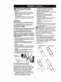
Read these instructions and this manual in
its entirety before you attempt to assemble
or operate your new lawn mower.
IMPORTANT: This lawn mower is shipped
WITHOUT OILOR GASOLINE tn the
engine°
Your new lawn mower has been assembled at the factory with the exception of
those parts left unassembled for shipping
purposes. To ensure safe and proper
operation of your lawn mower, all parts and
hardware you assemble must be tightened
securely. Use the correct tools as necessan/to ensure proper tightness. All parts
such as nuts, washers, bolts, etc., necessary to complete the assembly have been
placed in the parts bag°
WHEELS
ENGINE OIL
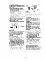
TO REMOVE LAWN MOWER FROM
CARTON
• Remove loose parts includedwith mower.
• Cut down two end comers of carton and
_ayend panel down flat.
• Remove all packing materials except
padding between upper and lower handle
and padding holding operator presence
control bar to upper handle.
° Rdl lawn mower out of carton and check
carton thoroughly for additional loose
parts,
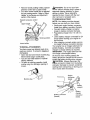
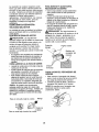
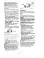
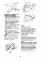
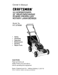
HOWTO SET UP YOUR LAWN MOWER
TO UNFOLD HANDLE
IMPORTANT: Unfold handles carefully so as
not to pinch or damage control cables
• Raise handles until lower handle section
locks into place in mowing position.
= Remove protecf_vepadding, raise upper
handle section Into place on lower handle
and tighten both handle knob&
4
• Remove handle padding holding operator
presence control bar to upper handle.
o Your lawn mower handle can be adjusted
for your mowing comfort. Refer to "Adjust
Handle" in the Sercice and Adjustment
section of this manual.
Operator
bar
d_IbCAUTION: Do not run your lawn
mower without mulcher plug in place or
approved clipping deflector or grass
catcher in place. Never attempt to
operate the lawn mower with the rear
door removed or propped open.
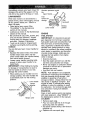
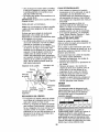
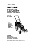
TO PREPARE BATTERY
NOTE: Your battery must be charged
before you can start your lawn mower.
° Disconnect engine battery connector
(male) from battery connector (female)
• Connect battery charger connector
(male) to battery connector (female).
• Plug battery charger into 110 volt A.C.
outlet.
° Leave battery charger connected for 24
hours before starting your engine for
the first time.
, After charging, connect engine connector (male) to battery connector (female),
Your engine has an integral alternator for
partial charging. Connect your battery
charger to charge battery as required.
IMPORTANT: The engine alternator will
not charge a discharged battery.
At the end of the mowing season the
battery should be charged for 48 hours to
protect the battery during winter storage.
_b.OAUTION: Always disconnect the
engine connector (male) from the battery
connector (female) to prevent accidental
starting when transporting or storing your
lawn mower after the season.
presence control
Upper handle
Jff up
Mowing position
/
Lower handle
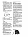
TO INSTALL ATTACHMENTS
Your lawn mower was shipped ready to be
used as a mulcher. To convert to bagging or
discharging:
• Open rear door and remove mulcher plug.
Store mulcher plug in a safe place.
° You can now install catcher or optional
clipping deflector,
, 1"o return to mulching operation, install
muicher plug into discharge opening of
mower.
Engine
connector
(male)
Mulcher plug
%
Battery
charger
Battery connector
(female)
5
Battery
charger
connector
(male)
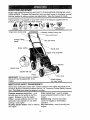
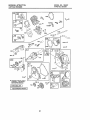
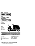
KNOW YOUR LAWN MOWER
READ THIS OWNER'S MANUALAND SAFETY RULrES BEFORE OPERATING YOUR
LAWN MOWER, Compare the illustrations with your lawn mower to familiarize yourself
with the location of various controls and adjustments. Save this manual for future
i
rl,
ii
,111
,
,,i,,_.111
_
_
These symbols may appear on your lawn mower or in literature supplied with the
product. Learn and understand their meaning,
CAUTION
OR WARNING
i1,1
F..NGINt_
ON
FAST
F.,NGtNE
OFF
8LOW
CHOKE
FUEL
OIL
, ,,,,,,
DANGER, KEEP HANDS
AND FEET AWAY
,,,
,,,, ,,,,,,,,,,,
,111
Engine zone
control cable
presence control bar
Drive control lever
Auxiliary starter
handle
Key" start switch
Grass catche_
Handle
knob
oil cap w/dipstick
Housing
Mulcher plug
Gasoline filler
Primer
Drive cover
IMPORTANT: This lawn mower is shipped
WITHOUT OIL OR GASOLINE in the
engine,
i
MEETS
U['l
1,1[11111
CPSC SAFETY
, Wheel adjuster
('on every wheel)
, u I i,iii1,11,11
REQUIREMENTS
Sears rotary walk-behind power lawn mowers conform to the safety standards of the
American National Standards Institute and the US. Consumer Product Safety CommissTon. The blade turns when the engine is running.
,11,11,
i
,,
i q!lll!
! :
_m-
Drive control lever - used to engage
power-prope!Ied forward motion of lawn
mower.
Mulcher plug - must be removed to
convert to bagging or discharging
operation.
Key start switch - used for starting the
engine.
Operator presence control bar - must
be held down to the handle to start the
engine. Release to stop the engine,
Primer - pumps additional fuel from the
carburetor to the cylinder for use when
starting a cold engine,
Auxiliary starter handle- used for starting
the engine,
6
-
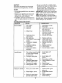
TO ATTACH
The operation of any lawn mower can
result in foreign objects thrown into the
eyes, which can result in severe eye
damage.
Always wear safety glasses or
eye shields while operating your lawn
mower or performing
any adjustments
or
repairs, We recommend
a wide vision
safety mask over spectacles or standard
safety glasses.
SPEED
CAUTION;
Do not
mower without clipping
approved grass catcher
attempt to operate the
the rear door removed
The engine speed was set at the factory
for optimum performance,
Speed is not
adjustable,
ENGINEZONE
CONTROL
_CAUTION=
Federal regulations
require an engine control to be installed
on this lawn mower in order to minimize
Hinge
bracket
the risk of blade contact injury_ Do not
under any circumstances
attempt to
defeat the function of the operator control,
The blade turns when the engine Is
running.
Your lawn mower ts equipped with an
operator presence control bar which
requires the operator to be positioned
behind the lawn mower handle to start
run your lawn
deflector or
in place. Never
lawn mower with
or propped open,
door
Grass
catcher frame
tabs
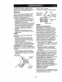
TO EMPTY GRASS CATCHER
° To remove grass catcher, release
operator presence control bar to stop
engine.
, Lift up rear door and remove the grass
catcher by the handle.
NOTE: Do not drag the bag when emptying; it will cause unnecessary wear.
and operate the lawn mower.
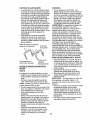
TO ADJUST CUTTING HEIGHT
• Raise wheels
CATCHER
• The grass catcher is secured to the
lawn mower housing when the rear
door is lowered onto the grass catcher
frame.
HOWTO USEYOUR LAWN MOWER
ENGINE
GRASS
• Close the lift top lid. Lift top lid must be
closed while operating lawn mower.
- Lift the rear door on the mower housing
and place the grass catcher frame onto
the formed tabs on the rear door hinge
bracket.
for low cut and lower
wheels for high cut.
° Adjust cutting height to suit your
requirements.
Medium position is best
for most lawns.
• To change cutting height, squeeze
adjuster lever toward wheel,
Move
wheel up or down to suit your require -=
mentso Be sure all wheels are in the
same setting_
NOTE: Adjuster
is properly positioned
when plate tab inserts into hole in lever.
Also, 9-position adjusters (if so equipped)
allow lever to be positioned
between the
plate tabs.
Lower Wheefs for High Cut
Plate Tab
Raise Wheels for Low Cut
7
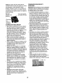
DRIVE CONTROL
• Self-propelling is controlled by holding the
operator presence control bar down to the
handle and pushing the drive control lever
forward until it clicks; then release the drive
control lever_
• Forward motion wi{I stop when the operator
presence control bar is released. To stop
forward motion without stopping engine,
release the operator presence control bar
slightly until the drive control disengages.
Holcl operator presence control bar down
to handle to continue mowing without selfpropelling.
o To keep ddve control engaged when
turning comers, push down on handle and
lift front wheels off ground while tuming
lawn mov_l_rato r presence
control bar '_,
\_ Drive
"" control
_._
_
Drive
control
Drive control
To engage
ddve control
BEFORE STARTING ENGINE "disengaged
OIL
Your lawn mower is shipped without oil in the
engine.
• Be sure mower is level and area around oi_
fill Is clean.
° Remove engine oil cap and fill to the full
line on the dipstick.
NOTE: Allow oil to settle down into
engine for accurate dtpstick reading.
° Engine holds 20 ozs. of oil For type and
grade of oil to use, see "ENGINE" in
Maintenance section of this manual.
° Pour oil stowly. Do not over fill.
• Check oil level before each use. Add oil if
needed. Fill to full line on dipstick.
° To read proper lever, tighten engine oi{ cap
each time.
° Reinstall engine olt cap and tighten.
• Change the oil after every 25 hours of
operation or each season. You may need
to change the oil more often under dusty,
dirty conditions.
GAS
• Fill fuel tank. Use fresh, clean, regular
unleaded gasoline with a minimum of 87
octane. Do not mix oil with gasoline.
Purchase fuel In quantities that can be
used within 30 days to assure fuel
freshness.
WARNING: Experience indicates that
hol blended fuels (called gasohot or
using ethanol or methanol) can attract
moisture which leads to separation and
formal]on of acids during storage. Ack_licgas
can damage the fuel system of an engine
while in storage. To avoid engine problems,
the fuel system should be emptied before
storage of 30 days or longer. Drain the gas
tank, start the engine and let it run until the
fuel lines and carburetor are empty. Use fresh
fuel next season, See Storage tnstructions for
additional information. Never use engine or
carburetor cleaner products in the fuel tank or
permanent damage may occur.
TO START ENGINE
• To start a ce{d engine, push prfmer three
(3) times before trying to start. Use a firm
push. This step is not usually necessary
when starting an engine which has
already run for a few minutes.
• Hold operator presence control bar down
to the handle.
• Turn e_ectricstart key clockwise to crank
engine.
IMPORTANT: Do not crank engine more
than five continours seconds between eahc
time you try to start. Wait 5 to 10 seconds
between each attempt.
. To start engine using the auxiliary starter
hand{e, foIIow the steps above. Exchange
the use of the start key for starter handle.
Pull starter handle quickly. Do not altow
starter rope to snap back.
o To stop engine, release operator presence
control bar.
NOTE: In cooler weather it may be neces.,
san] to repeat priming steps. In warmer
weather over pdming may cause llooding
and englne will not start. If you do flood
engine wait a few minutes before attempting
to start and do not repeat priming steps.
Gasoline t_ller cap
(Discard
debris
plug
inside)
Engine oil cap
MULCHING MOWING TIPS
MOWINGTIPS
• Under certain conditions, such as very
tall grass, it may be necessary to raise
the height of cut to reduce pushing
effort and to keep from overloading the
engine and leaving clumps of grass
clippings. It may also be necessary to
reduce ground speed and/or run the
lawn mower over the area a second
tlmeo
• For extremely heavy cutting, reduce the
width of cut by overlapping previously
cut path and mow siowlyo
• For better grass bagging and most
cutting conditions, the engine speed
should be set in the fast position.
• When using a rear discharge lawn
mower tn mofst, heavy grass, clumps of
cut grass may not enter the grass
catcher. Reduce ground speed
(pushing speed) and/or run the lawn
mower over the area a second time.
• If a trall of clippings is left on the right
side of a rear discharge mower, mow in
a clockwise direction with a small
overlap to collect the clippings on the
next pass.
° Pores in cloth grass catchers can
become filled with dirt and dust with
use and catchers will collect less grass.
To prevent this, regularly hose catcher
off with water and let dry before using.
= Keep top of engine around starter clear
and clean of grass clippings and chaff.
This will help engine air flow and
extend engine life.
IMPORTANT: For best performance, keep
mower housing free of built-up grass and
trash. See "Cleaning" in MAINTENANCE
section of this manual.
° The special mulching blade will recur the
grass clippings many times and reduce
them in size so that as they fall onto the
lawn they will disperse into the grass and
not be noticed, Also, the mulched grass will
biodegrade quickly to providenutrients for
the lawn. Always mulch with your highest
engine (blade) speed as this will provide
the best recurring action of the blades.
o Avoid cutting your lawn when It iswet. Wet
grass tends to form clumps and interferes
with the mulching action. The best time to
mow your fawn is the eady aftemoonoAt
this time the grass has dded and the newly
cut area will not be exposed to the direct
sun.
° For best results, adjust the lawn mower
cutting height so that the lawn mower cuts
off only the top one-third of the grass
blades, If the lawn is overgrown it will be
necessary to raise the height of cut to
reduce pushing effort and to keep from
overloading the engine and leaving
clumps of mulched grass. For extremely
heavy mulching, reduce your width of cut
by overlapping previously cut path and
mow slowly.
° Certain types of grass and grass conditions may require that an area be mulched
a second time to completely hide the
clippings° When doing a second cut, mow
across or perpendicular to the first cut path.
° Change your cutting pattern from week to
week. Mow north to south one week then
change to east to west the next week. This
will help prevent matting and graining of
the lawn.
Max. 1/3
9
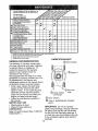
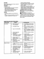
MAINTENANCE
SCHEDULE
FILL IN DATES
AS YOU COMPLETE
REGULAR SERVICE
M
O
SERVICE DATES
Chock for Loose Fasteners
Clean/inspect Grass Catcher
(If Equipped)
Clean Lawn Mower
v'
v'
v'_v'
E_
v"
N
v'
Groan
(Power-Propelled
I..Indor DriveMowers)
Cover
Chock drive belt/pulleys
v'
v'3
RE (Power-Propelled Mowers}
ChecktSharpen/Replace Blado
Lubrication Chart
Clean Battery/Recharge
(E ectdo Start Mowers)
...........
,
Check Engine Oil Level
v'
N !Change Engine oil
G €_eanAlr,Filte,r .....................
Inspect
Clean
or Muffler
Replace Spark Plug
i,,'4
v'
v"2
• J
E episgA,. .erP p rCa.t.d
.......,;!
t
V'
1_
:,
! - Change mo_e often when operating under a heavy toad or tn high ambient temperatures
2 - Servicemote of{onwhen operatingtndirtyor dusty eond111or,
s.
3 -Repiace blades more often when mowing Insandy soil,
4 - Charge 48 hours el and of season.
GENERAL
LUBRICATION
CHART
RECOMMENDATIONS
Wheel Adjuster
The warranty on this lawn mower does
not cover items that have been subjected
to operator abuse or negligence. To
receive full value from the warranty,
operator must maintain mower as
instructed in this manual.
Some adjustments will need to be made
periodically to properly maintain your unit.
All adjustments in the Service and
Adjustments section of this manual should
be checked at least once each season.
° Once a year, replace the spark plug,
replace air filter element and check
blade for wear. A new spark plug and
clean/new air filter element assures
proper air-fuel mixture and helps your
engine run better and last longer.
• Follow the maintenance schedule in
this manual
BEFORE EACH
gtne oil
(_) Rear door
hinge
(_) Handle bracket
mounting pin
(_) Spay lubricant
Refer to MAINTENANCE
section.
USE
• Check engine oil level.
• Check for loose fasteners.
LUBRICATION
"ENGINE"
IMPORTANT;
Do not oit or grease
plastic wheel bearings. Viscous lubricants
Keep unit well lubricated (See "LUBRICATION CHART").
will attract dust and dirt that will shorten
the life of the self lubricating bearings. If
you feel they must be lubricated, use only
a dry, powdered graphite type lubricant
sparingly.
10
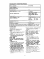
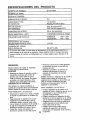
PRODUCT
SPECIFICATIONS
917.377830
MODEL NUMBER
SERIAL
NUMBER
DATE OF PURCHASE
6.0
HORSEPOWER:
GASOLINE
O1LTYPE
CAPACITY/TYP
1.6 QUARTS
UNLEADED
E:
SAE 30 (ABOVE 32°F)
SAE 5W-30 (BELOW 32°F)
(API-SF/SG/SH):
OIL CAPACITY:
20 OZS.
SPARK PLUG(GAP:
CHAMPION
.030")
,
SOLID STATE IGNITION
AIR GAP:
.005" - .007"
,007" - .009"
,I,,L
35-40 F]'. LBS.
The m0del and sedal numbers
wilt be found
both serial
on a decal attached
number
and date
io ihe rear Of the
of purchase
}n space
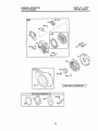
o Remove blade and attaching hardware
(bolt, lock washer and hardened
washer).
NOTE: Remove the blade adapter and
check the key inside hub of blade
adapter. The key must be in good
condition to work properly. Replace
adapter if damaged.
MOWER
Always observe
performing
any
TIRES
,
OR J19LM
.010 IN.
BLADE BOLTTORQUE:
lawn mower housing.Record
3rovided above,
RJ19LM
INTAKE:
EXHAUST:
VALVE CLEARANCE:
LAWN
REGULAR
safety rules when
maintenance.
o Keep tires free of gasoline, oil, or insect
control chemfcats which can harm
rubber.
• Avoid stumps, stones, deep ruts, sharp
objects and other hazards that may
cause tire damage.,
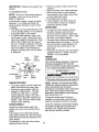
BLADE CARE
TO REPLACE BLADE
° Position the blade adapter on the
engine crankshaft. Be sure key in
adapter and crankshaft keyway are
aligned.
° Position blade on the blade adapter
aligning the two (2) holes in the blade
with the raised lugs on the adapter.
• Be sure the trailing edge of blade
(opposite sharp edge) is up toward the
engine.
° Install the blade bolt with the lock
washer and hardened washer into
blade adapter and crankshaft.
° Use block of wood between blade and
lawn mower housing and tighten the
blade bott, turning cfockwlse.
o The recommended tightening torque is
35-40 ft. lbs.
For best results, mower blade must be
kept sharp.
Replace bent or damaged
blades.
TO REMOVE BLADE
• Disconnect spark plug wire from spark
plug and place wire where it cannot
come in contact with spark plug.
• Turn lawn mower on tts side, Make
sure air filter and carburetor are up_
• Use a wood block between blade and
mower housing to prevent blade from
turning when removing blade bolt,
• Protect your hands with gloves and/or
wrap blade with heavy cloth.
° Remove blade bolt by turning counterclockwise.
11
• Remove hubcaps, hairpin cotters and
washers.
• Remove wheels from wheel adjusters.
• Remove any trash or grass cuttings
from inside the dust cover, pinion and/
or drive wheel gear teeth.
- Put wheels back in place.
° If after cleaning, the drive wheels do
not turn freely, contact your nearest
authorized service center.
GEAR CASE
IMPORTANT: Blade bolt is grade8 heat
treated.
TO SHARPENBLADE
NOTE: We do not recommend sharpening blade - but if you do, be sure the
blade is balanced.
Care should be taken to keep the blade
balanced. An unbalanced blade will
cause eventual damage to lawn mower
or engine.
o The blade can be sharpened with a file
or on a grinding wheel. Do not attempt
to sharpen while on the mower.
* To check blade balance, drive a nail
into a beam or wall. Leave about one
inch of the straight nail exposed. Piace
center hole of blade over the head of
the nail. If blade is balanced, it should
remain in a horizontal position. If either
end of the blade moves downward,
sharpen the heavy end until the blade
is balanced.
Crankshaft
keyway
Blade
ada )tar
Blade
Key
._._ :.,-_
bolt
'
Hardened
washer
T
g
edge
° To keep your drive system working
properly, the gear case and area
around the drive should be kept clean
and free of trash build-up. Clean under
the drive cover twice a season.
• The gear case is filled with lubricant to
the proper level at the factory. The only
tlme the lubricant needs attention is if
service has been performed on the
gear case.
- If lubricant is required, use only Texaco
Starplex Premium 1 Grease, Part No°
750369. Do not substitute.
ENGINE
LUBRICATION
-../
i&i'-:_',,_ Crack.
Use only high quality detergent oit rated with
API service ciassificalion SF,, SG or SH.
Setect the oil's SAE viscosity grade according
to your expected operating temperature.
Blade
adapter
TI_'MPERA_URE RANGE ANTICIPATED
GRASS CATCHER
, The grass catcher may be hosed with
water, but must be dry when used.
° Check your grass catcher often for
damage or deterioration. Through
normal use it will wear. If catcher
needs replacing, replace only with a
manufacturer approved replacement
catcher. Give the lawn mower model
number when ordering.
DRIVE WHEELS
Check front drive wheels each time
before you mow to be sure they move
freely.
The wheels not turning freely means
trash, grass cuttings, etc. are in the drive
wheel area and must be cleaned to free
drive wheels.
If necessary to clean the drive wheels,
check both front wheels.
BEFORE NEXT OIL CHANGE
NOTE: Although multi-viscosity oils (5W30,
10W30 etc,) improve sta_ng in cold weather,
these multi*viscosity oils will result in
increased oil consumption when used above
32°F. Check your engine oil level more
frequently to avoid possible engine damage
from running low on oil.
Change the oil after every 25 hours of
operation or at least once a year if the lawn
mower is not used for 25 hours in one year.
Check the crankcase oil level before starting
the engine and after each five (5) hours of
continuous use. Tighten oil plug securely
each time you check the oil level.
12
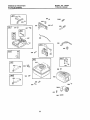
TOCHANGEENGINEOIL
Back
NOTE: Beforetippinglawnmowerto drain
oil,drainfueltankby runningengineuntilfuel
tankisempty.
• Disconnect
sparkplugwirefromspark
plugandplacewirewhereit cannotcome
Incontactwithsparkplug.
- Removeengineoilcap;layasideon a
cleansurface.
• l]p lawnmoweron itssideas shownand
drainoilintoa suitablecontainer.Rock
lawnmowerbackandforthto removeany
oil trappedinsideof engine,
- Wipeoffanyspilledoflonlawnmowerand
on sideof engine.
• Fill engine with oil Fill only to 'dqe"FULL"
line on the dipstick. DO NOT overfill.
_, Replace engine oll cap.
° Reconnect spark plug wire to spark plug.
Slots
Cover
tabs
Cartridge
Cover
MUFFLER
inspect and replace corroded muffler as it
could create a fire hazard and/or damage.
SPARKPLUG
Change your spark plug each year to
make your engine start easier and run
better. Set spark plug gap at .030 inch.
CLEANING
IMPORTANT: For best performance, keep
mower housing free of built-up grass and
trash. Clean the underside of your mower
after each use.
lj.Contatner
&CAUTION:
Disconnect spark plug
wire from spark plug and place wire
where it cannot come in contact with the
spark plug.
• "rumlawn mower on its side.. Make sure air
filter and carburetor are up. Clean the
underside of your lawn mower by scraping
to remove buildup of grass and trash.
o Clean engine often to keep trash from
accumulating. A dogged engine runs
hotter and shortens engine llfe.
• Keep finished surfaces and wheels free of
al! gasoline, oil, etc,
° We do not recommend using a garden
hose to clean lawn mower unless the
electrical system, muffler, air filter and
carburetor are covered to keep water out°
Water In engine can result in shortened
engine fife_
GLEAN UNDER DRIVE COVER
Clean under drive cover at least twice a
season_Scrape underside of cover with putty
knife or similar tool to remove any buildup of
trash or grass on underside of drive cover.
AIR FILTER
Your engine will not run properly and may
be damaged by using a dirty air filter.
Replace the atr filter every year, more
often if you mow in very dusty, dirty
conditions.
TO CLEAN AIR FILTER
= Loosen
screw and tilt cover to remove.
° Carefully remove cartridge.
• Clean by gently tapping on a flat
surface.
If very dirty, replace cartridge.
as_CAUTION:
Petroleum solvents, such
erosene, are not to be used to clean
cartridge.
They may cause deterioration
of the cartridge.
Do not oil cartridge.
Do
not use pressurized
air to clean or dry
cartridge.
• Install cartridge, then replace cover
making sure the tabs are aligned with
the slots In the back plate. Fasten
screw securely.
13
AUTION: BEFORE PERFORMING
SERVICE OR ADJUSTMENTS:
•
Release control bar and stop engine.
•
Make sure the blade and all moving
parts have completely stopped.
°
Disconnect spark plug wire from
spark plug and place where it can
not come in contact with plug.
LAWN MOWER
TO ADJUST CUTTING HEIGHT
See "TO ADJUST CUTTING HEIGHT" in
the Operation section of this manual.
REAR DEFLECTOR
The rear deflector, attached between the
rear wheels of your lawn mower, is
provided to minimize the possibility that
objects will be thrown out the rear of the
lawn mower into the operator's mowing
position. If the rear deflector becomes
damaged, it should be replaced.
TO REMOVE/REPLACE DRIVE BELT
• Remove drive cover. Remove belt by
pushing down on gear case pulley and
rolling beff off it.
• Turn lawn mower on its side with
carburetor and fuel cap up.
• Remove blade.
° Remove debrls shield._
° Remove belt from engine pulley on
crankshaft.
= Instatl new belt by reversing above
steps.
= Always use factory approved belt to
assure fit and long life.
Drive
cover
o To change from medium low to medium
hlgh position, the upper and lower handle
sections will have to be tumed over.
° Remove the cable dips.
• Remove the controls and operator
presence control bar from the upper
handle.
• Remove the starter rope guide from the
upper handle.
° Remove hairpin cotters.
° Disconnect the lower handle from the
handle brackets.
° Turn the handle over and reassemble the
hairpin cotters that have been removed.
• Reassemble the starter rope guide.
° Reassemble the controls and the operator
resence control bar to the upper handle.
CAUTION: The operator presence
control bar must pivot freely to permit
blade brake engagement when control
bar is released. Do not over tighten the
fasteners holding the controls to the
upper handle.
• To change from medium tow to high
position only the upper handle section
will have to be turned over.
o To change from medium low to low
position, only the lower handle section
wtli have to be turned over.
Shipping position
Medium low
Medium high
Belt
Push
down
TO ADJUST
Low
HANDLE
Your lawn mower
handie can be raised
or
lowered for your mowing comfort.
Four
(4) positions are available:
high, medium
high, medium low and low. Handles are
shipped mounted in the medium low
posltlon.
14
Lower" handle
Lower Frame
Squeeze to
remove
(Frames must
, be fully
Handle
bracket
--7'
_
9 t
,
-'
Hairpin cotter
•
TO ASSEMBLE
Frame
GRASS CATCHER
o Insert teg of tubular frame through front
opening of grass catcher and thread
frame into sewn hem of bag.
NOTE: Keep bag hem gathered on the
straight leg of the tubular frame.
, When frame comes out the other end of
sewn hem, immediately work the end of
frame down inside the bag as shown in
inset.
° Slide sewn hem evenly around the
tubular frame until both ends of frame
are exposed out of the front opening.
• Assemble lower frame to tubular frame
as shown. Be sure handle is outside of
bag and frames are fully seated as
shown in inset.
• Slip vinyl bindings over frame.
NOTE: If vinyl bindings are too stiff, hold
them in warm water for a few minutes. If
bag gets wet, let it dry before using.
° Close the flip !id. Flip lid must be closed
while operating lawn mower.
_OAUTION:
Do not run your lawn
mower without clipping deflector or
approved grass catcher in place. Never
attempt to operate the lawn mower with
the rear door removed or propped open.
Lower frame handle
"N
__bindings
ENGINE
"
""
SPEED
Your engine speed has been faclory set,
Do not attempt to increase engine speed
or it may result in personal injury. If you
believe that the engine is running too fast
or too stow, take your fawn mower to an
authorized
service center for repair and
adjustment.
CARBURETOR
Your carburetor is not adjustable. If your
engine does not operate properly due to
suspected carburetor problems, take your
lawn mower to an authorized service
center for repair and/or adjustment.
IMPORTANT: Never tamper with the
engine governor, whtch is factory set for
proper engine speed. Overspeeding the
engine above the factory high speed
setting can be dangerous. If you think the
engine-governed high speed needs
adjusting, contact your nearest
AUTHORIZED service center, which has
proper equipment and experience to
make any necessary adjustments.
Tubular frame
!
,
Sewn hem
J
ENGINE
Sewn hem
t
Tubular
Flip lid
t5
Immediatelyprepareyour tawn mowerfor
storageat the end of the seasonor if the
unitwill not be usedfor 30 days or more.
LAWN MOWER
Operator
When lawn mower is to be stored for a
period of time, clean it thoroughly, remove
all dirt, grease, leaves, etc Store in a
clean, dry area.
o Clean entire lawn mower (See
"CLEANING" in the Maintenance
section of this manual).
• Lubricate as shown in the Maintenance
section of this manual°
• Be sure that all nuts, bolts, screws, and
pins are securely fastened. Inspect
moving parts for damage, breakage
and wear, Replace if necessary.
° "Touch up all rusted or chipped paint
surfaces; sand lightly before painting.
HANDLE
You can fold your lawn mower handle for
storage.
• Squeeze the bottom ends of the lower
handle toward each other until the
lower handle clears the handle bracket,
then move handle forward.
• Loosen upper handle mounting bolts
enough to allow upper handle to be
folded back.
IMPORTANT:
When folding the handle
for storage or transportation, be sure to
fold the handle as shown or you may
damage the control cables.
o When setting up your handle from the
storage position, the lower handle will
automatically lock into the mowing
position.
forward for _'_?"
Lower handle
Handle
racket
Squeeze to fold
Hairpin cotter
presence control
Upper Handle ---_iJ
//,,_
_
sto,age
o_=.,_"
,_)
Fold
backward
Mowing
Lower handle
position
ENGINE
FUEL SYSTEM
IMPORTANT:
It Is important to prevent
gum deposits from forming in essential
fuel system parts such as carburetor, fuel
_ter, fuel hose, or tank during storage.
Also, experience indicates that alcohol
blended fuels (called gasohol or using
ethanol or methanol) can attract moisture
which leads to separation and formation
of acids during storage. Acidic gas can
damage the fuel system of an engine
while in storage.
• Drain the fuel tank.
,, Start the engine and let it run until the
fuel lines and carburetor are empty,
o Never use engine or carburetor cleaner
products in the fuel tank or permanent
damage may occur.
, Use fresh fuel next season.
NOTE; Fuel stabilizer is an acceptable
alternative in minimizing the formation of
fuel gum deposits during storage. Add
stabilizer to gasoline in fuel tank or
storage container. Always follow the mix
ratio found on stabilizer container. Run
engine at least t0 minutes after adding
stabilizer to allow the stabilizer to reach
the carburetor. Do not drain the gas tank
and carburetor if using fuel stabilizer.
ENGINE OIL
Drain oil (with engine warm) and replace
with clean engine oil. (See "ENGINE" in
the Maintenance section of this manual).
CYLINDER
° Remove spark plug,
o
Pour one ounce (29 ml) of oil through
spark plug hole Into cylinder,
o
Pull starter handte slowly a few times to
distribute oil,
16° Replace with new spark plug.
= Cover your unit with a suitable protective cover that does not retain moisture.
Do not use plastic., Plastic cannot
breathe which al!ows condensation to
form and will cause your unit to nJsL
IMPORTANT:
Never cover mower while
engine and exhaust areas are still warm.
_CAUTION:
Never store the lawn
mower with gasoline in the tank inside a
building where fumes may reach an open
flame or spark° Allow the engine to cool
before storing in any enclosure.
BATTERY
Disconnect the battery from the engine
connector and charge battery 48 hours.
OTHER
o Do not store gasoline
to another.
from one season
o Replace your gasoline can if your can
starts to rust° Rust and/or dirt in your
gasoline will cause problems°
= If possible, store your unit indoors and
cover it to give protection from dust and
dirt,
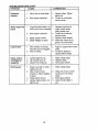
TROUBLESHOOTING
CHART
PROBLEM
Does not start
CAUSE
CORRECTION
1.
2.
3.
Dirty air filter_
Out of fuel
Stale fuel.
!.
2,
Clear_'replace
Fill fuel tank.
air filter,
3.
4_
Water in fuel.
4.
Drain tank and refill with
fresh clean fuel.
Drain fuel tank and
carburetor and refill tank
5.
Spark plug wire is
disconnected,
5.
with fresh gasoline,
Connect wire to plug.
6.
7.
Bad spark plug.
6,
Loose blade or broken blade 7.
Replace spark plug,
Tighten blade bolt or
8.
adapter.
Control bar in released
9.
position,
Control bar defective.
replace blade adapter:
Depress control bar to
handle.
10. Weak Battery
!1. Disconnected battery
connector.
,
Loss of power
1.
8.
9. Replace control bar.
10. Charge battery.
11, Connect battery to engine.
i
Rear of lawn mower housing
1.
or cutting blade dragging
Poorcut-uneven
2o
in heavy grass.
Cutting too much grass.
3,
Dirty air filter.
4.
Buildup of grass, leaves,
and trash under mower.
5.
Too much oil in engine.
6.
Walking speed too fast.
1.
Worn, bent or loose btade.
2.
Wheel heights
3.
Buildup of grass, leaves
and trash under mower.
uneven.
17
Set to "Higher Cut"
position.
2,
Set to "Higher Cut"
position.
3, Clean/replace air filter.
4o Clean underside of mower
housing,
& Check oil level,
6, Cut at slower walking
speed,
1.
Replace blade. Tighten
blade bolt,
!2.
Set all wheels at same
3.
height
Clean underside
mower housing,
of
TROUBLESHOOTING
PROBLEM
CHART
CORRECTION
CAUSE
i
Excessive
vibration
=
2_
,
,,,,,,i,,
,
,,,,
i,,i,,,,,i
, ,,
Wem, bent or goose blade.
1,
Bent engine crankshaft.
2.
,rn,l,
Starter rope hard
topull
ll,
Replace blade, "lighten
blade boll
Contact an authorized
service center_
f
1.
Engine flywheel brake is on
when control bar is released.
1,
2.
Bent engine crankshaft.
2.
3.
Blade adapter broken.
3,
4.
Blade dragging in grass.
4.
Depress control bar to
upper handle before
pulling starter rope.
Contact an authorized
ser_ce center.
Replace blade adapter.
Move lawn mower to cut
grass or to hard surface.
,
Loss of drive
1.
Drive wheels not turning
2,
with drive control engaged,
Belt not driving
1,
: 2.
Adjust or replace drive contro!
cable.
Put belt on pul{eys or
replace belts if broken,
Grass catcher
not filling (if so
equipped)
1.
2,
Cutting height too low.
Uft on blade worn off.
3,
Catcher not venting air.
,,i,
Hard to push
, i,,
,,i,,,
1.
2.
3.
Raise cutting heighL
Replace blade.
Clean grass catcher.
i
1.
Grass is too high or wheel
1.
Raise cutting height.
2.
height is too low.
Rear of lawn mower
2.
Raise rear of lawn mower
housing or blade dragging
housing one (1) setting
3,
in grass.
Grass catcher too full.
3,
higher,
Empty grass catcher,
4.
Handle height position not
4.
right for you.
18
, ,i,,i,
Adjust handle height to
suiL
,liJJJJ,,
Garantfa
Reglas de Seguridad
MontaJe
Operaci6n
Mantenlmlento
Programa de Mantenlmiento
19
19
21
23
27
27
Especfficacianes del Producto
Servlcio y Adjustes
Almacenamiento
ldentificaci6n de problemas
Partes de repuesto
Orden de Partes
GARANTIA LIMITADA DE DOS AI_IOS PARA LA SEGADORAA
28
31
33
34
Vea e{ manual
ingl6s del duefio
Contratapa
MOTOR CRAFTSMAN
Per dos (2) aSos, a partir de la fecha de compra, cuando esta Segadora Craftsman se mantenga,
lubfique y afine segt_n les tnstrucck_nespara la operacl6n y e! mantenlm_ento en e! manual det duefio,
Sears reparar_ gratis todo defecto en el material y la mane de obra,
Si 1aSegadora Craftsman se usa para fines comerciales o de arrlendo, esta garantla s61ose aplica per
novenla (90) d_as a parlir de la fecha de compr&
Esta Garantfa no cubre:
e Art[culas que se desgastan durante el use norma! tales come las cuchillas segadoras rotatorias, los
adaptedores de la cuchilla, tes co[Teas, {os fiitros de afre y las bujias.
. Reparaciones necesarias debido al abuse o a la negllgencia del operador, inclw6ndose a los
clg0e_TJesdoblados y a la fa_ de mantenlmtento del equipo seg0n las instrucciooes que se incluyen
en el manual del dueSo.
EL SERVIC10 DE GARANT(A ESTA DISPON1BLE al devoiver 1asegadpra a motor Craftsman al cenl_cY
depar_ento de servtcio Sears mas cercano en los Eslados Unidos.. Esta garant[a se aplica selamente
mlentras el producto este en Liso en ]os Estados Unidos..
Esta Garantla le otorga derechos legales especflicos, y puede que _rnbl_n tenga otros derechos que
var[an de estado a estado.
Sears, Roebuck and Co,, D/817WA, Hoffrnan Estates, IL 60179 USA
Los estandrares de seguridad exigen la presencla
del operator en los controles para reducir a un
mtntmo el desgo de lestonarse, Su unidad viene
equipada con dtchos contreles. Par nlngun mo_o
Irate del etlminar la funci6n de los controles que
exigen la presencta del opemdor_
ENTRENAMIENTO:
. Lea este manual det operador
cuidadoeamenteo Fam[ltar/cese con los
conlroles y aprenda a operar su segadom en
forma adecuad& Aprenda a parar su segadora
r,_pidamente,
• No permita que los niRos usen su segadora.
Nunca permita que los adultos operen la
segadora sin contar con las lnstrucdones
adecuadas.
• Mantanga et _rea de operact6n despejada
de genre, especlaJmente de nifies pequefios
y de animales dom6sl_cos.
• Use la segadora solamente para los fines
propuestos per ef fabficante y
segOn
tas expltcaciones descritas en este manual
° No apere la segadora sl se ha cafdo o dafiado
en cualqulera forrna Siempre repare los dafios
antes de usada
• No use aceesofios que no hayan side
recomendados per el fabflcante El use de
dichos accesorios puede ser pellgroso
, La cuchilla gira cuando el motor est_
funcionando.
PREPARACl6N:
. Siempre revise cutdadosamente el _rea que
se va a segar y desp6jela de todas las
piedras, palos, alambres, huesos y otros
abjetos extra_os_ Estos objetos serAn
lanzados con ta cuchilla y pueden productr
lesiones graves.
• Siempre use anteojos de seguridad o
protectores de ojos cuando arranque y
durante el tiempo que use la segadora.
19
° Vfstase en forma adecuadao No opere ta
segadora sin zapatos o con sandalias
abiertaso Use solamente zapatos s611dos
con buena traccl6n cuando s[egue.
• Revise el estanque de combustible antes de
hacer arrancar el motor. No Ilene el
estanque de gasoltna en recintos cerrados,
nl cuando el motor est& funclonando o
cuando est_ caltente. Permtta que el motor
se enfrfe per varies mlnutos antes de Itenar
et estanque de gasolina. Llmpte toda la
gasolina derramada antes de hacer
arrancar el motor.
- Siempre haga los ajustes de altura de las
ruedas antes de hacer arrancar su
segadora. Nunca trate de hacer 6sto
mientras que el motor esi& funcionando.
• Slegue siempre durante el dfa o con buena
luz artificial
OPERACI6N:
o No haga funcienar et motor en
recintoscerrados. Los gases do escape son
peligrosos..
. Nunca corte el c_sped tlrando la segadora
hacia usted. Slegue a tray,s de la cam de
las pendtentes, nunca hacla arrlba o hacla
abajo puss puede perder el equtlibrto. No
slegue pendlentes demaslado emptnadas.
Tenga cutdado cuando opere la segadora en
terreno dispareJo o cuando cambie de
direccI6n- mantenga un buen equilibrio.
• Nunca opere la segadora sin tas
protecctones adecuadas, las planchas, el
recogedor de c@spedy otros dtspositivos de
seguridad en su lugan
MANTENIMIENTO
Y ALMAOENAMIENTO:
•Revtse la cuchilla y los pemos de montaje
del motor a menudo, para asegurarse que
est_n apretados en la forma adecuada.
• Revise todos los pemos, tuercas y tomitlos a
tntewalos frecuentes, para vertficar si est_n
apretados en forma adecuada, y
asegurarseque la segadora se encuentra en
condiciones de funcionamlento seguro.
° Mantenga todos los dispositivos de
seguridad en su lugar y listos para funcionar.
. Para reducir el peligro de incendio,
mantenga el motor sin c_sped, hojas y grasa
o acelte en exceso..
. Revise et recogedor de c6sped a menudo
para verlficar st hay deterioro y desgaste y
cambie las bolsas desgastadas, Use
solamente las bolsas de repuesto
recomendadas per el fabficante de su
segadora o que cumplen con las
especlflcaclones de _ste.
° Siempre mantenga una cuchltla afilada en su
segadora.
° Stempre permita que et motor se enfrt'e
antes de guardada en cualquier rectnto
cerrado.
o Nunca guarde la segadora con combustible
en el estanque dentro de un edificio en
deride los gases pueden alcanzar una llama
expuesta o una fuente de ignici6n, tal come
e! calentador de agua, la estufa de
cafefacci6n, la secadora de ropa, etc.
• Mantenga sus ojos y su mente en la
segadora yen el ._rea que se est,. cortando,
No permita que otros intereses lo dtstralgan.
• No corte c_sped mojado o resbaloso. Nunca
corm mlentras est_ operando su segadora.
Siempre asegdrese de mantener el equillbrio
mantenga et mango agarrado firrnemente y
camtne.
• No ponga las manes 0 los pies cerca
odebajo de las partes rotatorias. Mant_ngase
aleJado de la abertura de descarga
en rode memento.
• Stempre pare et motor cuando se vaya
ocuando no est_ usando su segadora, o
antes de atravesar las entradas para autos,
los senderos, camlnos y _.reas cublertas de
ripio.
, Nunca didja la descarga del material hacta
los espectadores ni permtta a nadie cerca de
la segadora mientras la est@operando.
• Antes de ]imptar, inspeccionar o de reparar I
a segadora, pare el motor y est_
completamente seguro de que la cuchilla y
que todas las partes que se mueven se
hayan detenldo. Luego, desconecte el
alambre de la bujfa y mant_ngaJo alejado de
8sta para evltar el arranque per accidents.
• No continOe haclendo funcionar su segadora
sl le pega a un obJeto extra_o. Siga el
procedlmiento descrito anteriormente, luego
repare cualquler daSo antes de votver a
arrancar y de operar su segadora.
° No cambie los ajustes del regulador o
hagaque el motor ands a una velocidad
exceslva. Se pueden produclr da_os en el
motor y I esiones personales.
• No opere su segadora st vfbra fuera de Io
normal. La vtbracl6n exceslva es una
lndicaci6n de daSo; pare el motor, revise en
forrna segura la causa de la vibracl6n y haga
las reparaclones seg0n sea necesadoo
a_amPRECAUCI_)N:
el
bre de la buj(a ySlempre
p6ngalo desconecte
donde no pueda
entrar en contacto con la bujt_a, para evitar el
arranque per accidents, durante la preparaci6n, el transports, el ajuste o cuando se
hacen reparacioneso
per
_staPRECAUOI6N:
Es conocido
el
de de California que los gases de escape
del motor de este productor contienen
qufmtcos los cuates a ciertos nlveles, pueden
ocaslonar, c_ncer, defectos de nacimiento, y
otros daSos at slstema reproductive.
2O
Estos accesodos estaban disponibles cuando se produjo la segadora, No son faeilltados Junto al
cortacesped, Est_n disponibles en la mayoria de las tiendasde Sears yen los centros de servlcio. La
mayorfa de las t]endas Sears tambi_n pueden mandar a pedir partes de repuesto para usted, sl lee
proporclona el nOmerode] modelo de su segadora. Algunos de estos accesorios tal vez no se apliquen a
su segadora.
RENDIMIENTO
DE LA SEGADORA
DESVIADOR DE RECORTES
PARA SEGADORAS
CON DESCARGA
ill
ii ii
,,i,ii
TRASERA
JUEGOS
iiip.
PARA
LA ACOLCHADORA
PARA
SEGADORAS
CON
DESQARGA
RECOREOOR
TRASERA
__
MANTENIMIENTO
ESTAB|LIZADORES
PARA
SEGADORAS
CON
DESCARGA
RECOREOOR
LATERAL
ENVASI=S
DE GASOLINA
DE LA SEGADORA
i
i
SILENCIADQRES
CORREAS
CUCH]LLAS
ADAPTADORES
DE CUCHILLA
,lllll iilll
ii
FILTROS DE AIRE
, ,,LII.
illll
iii
iiill
lllL
BUJ{AS
ACEITE
_,UEDAS
...........
.... DEL MOTOR
PARA REMOVER LASEGADORA DE
LA CAJA DE CARTON
Lea eslas tnstrucciones y este manual
comptetarnente antes de tratar de monlar u operar
su eegadora nueva.
IMPORTANTE: Este cortac6sped viene SIN
ACEITE O GASOLINA en el motor.
• I%mueva las partes suettas que se lncluyen
con la segadora,.
• Corte las dos esqulnas de los exlremosde ta
caja de cart6n y tienda el panel del extremo
piano.
• Remueva todo el material de empaque, excepto
la curia entre el mango superior y _1Inferior, y ta
curia que sujefa la barra de los contro! que
exige la presencta de; eperador junto con el
mango superior.
= Haga rodar }a segadora hacia afuera de la caja
de cart6n y revise[a cuidadosamente para
vedficarsi todavla quedan partes suellas
adicionales.
Su segadora nueva ha sido montada an ta
f_brica con la excepci6n de aque[fas partes
que se dejaron sin montar pot razones de
envio. Todas las partes como las tuercas, las
arandelas, los pernos, etc. que son
necesarias para completar el montaje han sido
colocadas en la bolsa de partes. Para
asegurarse que su segadora functone en
forma segura y adeeuada, todas tas partes y
los articulos de ferreter{a que se monten
tienen que ser apretados seguramente, Use
las herramientas correctas, como sea
necesario, para asegurar que se apdeten
adecuadamente.
21
COMO PREPARAR SU SEGADORA
PARA PREPARAR LA BATER{A
PARA DESDOBLAR
AVISO: Su batert'a ttene que estar cargada
antes de que pueda hacer arrancar su
segadora.
o Desconecte el conector de{ motor (macho)
al conector de la baterfa (hembra)
= Conecte et conector del cargador de la
bateda (macho) al conector de fa bater[a
(hembra).
• Enchufe el cargador de la baterfa dentro del
enchufe de 110 volt C.A.
• Deje e{ cargador de ta baterfa conectado
par 24 horas antes de hacer arrancar su
motor par la prlmera vez_
• Despu6s de cargar, conecte el conector del
motor al conector de la baterfa.
EL MANGO
IMPORTANTE: Despliegue el mango con mucho
cutdado para no pellizcaJ o daSar los cables de
control,
° Levante los mangos hasta qua la secci6n del
mango Inferior se asegure an su lugar, en la
poslcldn para segar.
• Remueva ra curia protectcra, levante la secclSn
del mango superior basra su fugar en el mango
infedor, y apriete ambas manitlas del mango.,
Remueva la curia del mango que sujeta la barra
de los control que oxige la presencia del
operador jun_o con el mango superior.
° El mango do ta segadora puedo ajustarse
segOn Io acomode para segar Refi_rase a
"AJUSTE DEL MANGO" en la SecclSn do
Servicio y Ajustes de este manual
Su motor cuenla con un alternador Integrado
para carga parciaL Conecte su cargador de
baterfa para cargarla segSn sea necesario.
IMPORTANTE: El alemador del motor no
Barra de control qua
presencia del operador
cargara una bateria descargada.
AI final de la temporada de slega, la bateffa se
debe cargar par 48 horas para protegerla
durante el peffodo de almacenamiento an el
tnvierno.
Mango
Levantar
Stempre
co_nePRECAUCI6N:
desconecte
el
ctor def motor del conector
de la bater[a
Mango
PARA INSTALAR
para evitar el arranque par accldente at
transportar o guardar su segadora despu_s
de la temporada.
Posloi6n
para segar
Conector del
motor(macho)
LOS ACCESORIOS
$u segadora be enviada lista pare usarse coma
una acolchadora de capa vegetal. Para converlJrla
de modo qua pueda ensacar o descargar.
o Abra ta puerla trasera y remueva la tapon
acolchadora. Gu_rdela en un lugar seguro,
° Ahora puede instalarel recogedor o el
desvtador de recortes opclonal.
• Para volver a la operadSn de aco{chamlento
con capa vegetal,inslale la tapon acolchadora
en la aberk_rade descarga de la segadorao
Oargador
de la
bateria
Conector de la
bateda(hembra)
se_gaPRECAUCl6N:
haga functonar
su
dora sin la tapon No
acolchadora
aprobada
en su lugar, o sin el desvfador de recortes, o
sin el recogedor de c_sped, aprobados, en su
lugar. Nunca trate de operar la segadora
ouando se ha removtdo la puarta trasera o
cuando est& un poco ablerta.
22
Conector del
cargador de ta
bateria(macho)
FAMILIARICESE CON SU SEGADORA
LEA ESTE MANUAL DEL DUENO Y LAS REGLAS DE SEGURIDAD ANTES DE OPERAR SU
SEGADORA. Compare las ilustraciones con su segadora pare familiadzarse con la ubicaci6n de
los diversos controles y ajuste& Guarde este manual pare referencia en el futuro,
m
II
,i ...............
i
!'!'1
iii
i
i
ii
,,,
,111!1111111
II"'IIIH"
,,,,,
_r,,
.........
Estos s_'mbolospueden apareser sobre su segadora o en a iiteratura proporcionada con el producto.
Aprenda y comprenda sus sfgniflcados.
AT'rENCI_H
O
ADVERTF.,,NCIA
,i
,
MOTOR
ENCENOEOO
1,1!!
MOTOR
APAGADO
i!111
,
R/_PIOO
,i
,,,
LENTO
,
i
E£TRANGU
L&CION
COM.
ACEfTE PELfGRO, GUARDE LA£
:BUSTIBLE
MANO:9Y LOS P_E£LEJOS
iiiiiiii1[i,1[
I
lnterruptor de
arranquee de Ifave
I
i, lulnuull
'!IIIIIK ...........
Barra de control que exige la
presencia del operador
Cable de control de
zona del motor
Control de impulsi6n
Mango del
arrancador auxiliar
Mantila del
mango
Tape dei deposito de
del motor con varflla
de nivel
Recogedor del c_sped '--...
Caja
Tapon de la
acolchadera
Tape de1 depostto de I
gasolina
Cubferta de la
lmputsISn
IMPORTANTE: Este cortac_sped vlene SIN
ACEtTE O GASOLINA en et motor.
Ajustador de la rueda
(on cada rueda)
11111
CUMPLE .........................
CON LOS REQUISITOS DE SEGURIDAD
,
i
,1111
_:_
DE LA cPsc
Las segadoras a motor, que se conducen desde ta parte de arras, rotatodas, Sears, cumplen
con los estAndares de seguridad del American National Standards Institute y de la U.S, Corn
sumer Product Safety Commission, La cuchi,lla gtra cuando el motor est& functonando.
, iii,
iiiiiii
i,
i
,
iii
Barra de control que exlge la presencia del
operado - t[ene que sujetar.,se abajo, junto
con el mango, pare hacer arrancar el motor.
Su_ltela para parar el motor.
Cebador- bombea combus_Jble adiclonal
desde el carburador at cItindro pare uso
cuando se neceslta hacer arrancar un motor
frfo.
Mango del arrancador auxillarhacer arrancar el motor.
I
ii '1 iii
I!
Palanca de control de la impulsi6n - se
usa pare enganchar la segadora pare
movimiento hacla adelante impulsada a motor.
Tapon de ia acolchadera .- situada en la
abertura de la descarga y debe ser quitada
cuando se convierte la operaccl6n de
ensaoado a desearga.
tnterruptor de arranquee de Ilave- se usa
pare hacer arrancar el motor.
se usa pare
23
-
La operaci6n de cualquier segadora puede
hacer clue satten objetos extra5os dentro de
sus ojos, to que puede producir dafios graves
en _stos. Slempre use anteojos de seguridad
o protecci6n para los ojos mientras opere su
segadora o cuando haga ajustes o
reparaolones. Recomendamos una mascara
de seguddad de visiSn amplia, para uso
espejuelos o anteojos de seguridad
estandarte.
COMO USAR SU SEG_&3ORA
VELOOIDAD
DEL MOTOR
La veloctdad del motor se estableci6 en la f&brica
para un rendtmlento 6p_mo° La velocidad no se
puede ajustar.
CONTROL DE ZONA DEL MOTOR
PARA MONTAR Y ADJUNTAR
RECOGEDOR DE C_SPED
• Cierre la tapa so}_ble, La tapa soltabte debe
oscar cerrada cuando se esla operando la
segadora,
• Levante la puerla l_'aserade ta caja de la
segadora y ponga e! bastidor dsl recogedor de
c_sped en tas orejas formadas en ei puntal de
bisagra de ]a puerta traser&
° El recogedor de c_sped esta asegurado en Ia
caja de Ia segadora cuando se baja la puerta
trasera para descansar en el bas_dor det
recogedor de c6spsd
No
funclonar
se_gaPRECAUCI6N:
haga
su el
dora sin el desv}ador de recortes o sin
recogedor de c_sped, aprobados, en su
lugar. Nunca trate de operar la segadora
cuando se ha removldo la puerta trasera o
cuando est,_ un poco abierta°
t_ePRECAUCI6N"
Las regulactones
tales exlgen que se Instale un control para
el motor en esta segadora para reducir a un
m,rnlmo et desgo de {esionarse debido al
contacto con la cuchilla. Por ning_3nmotivo
trate de elimlnar [a funciSn del control dsl
Puntal de
bisagra
operadoro La cuchflla gira cuando eEmotor est#.
funclonando,
• Su segadora vtene equlpada con una baEa de
control que exige la presencla dot operador, Io
que requlersque el operador est_ detr_ del
mango de la.segadora para hacerla arrancar y
operarla.
PARA AJUSTAR LA ALTURA DE CORTE
OreJas
formadas
PARA VACIAR
C#.SPED
EL RECOGEDOR
DE
Para remover el recogedor del c_sped,
pare el motor el allvtar la barra de contro{
que exige la presencia del operador.
° Levante la puerta de atras y remora el
recogedor del c_sped por el mango.
AViSO: El ajustador esta corr_ente
colocado cuando las orejas de la placa estf_n
Insedadas en el agujero del mango, Tambl#n, los
ajustes de 9 posfciones (si equipado) pen'nltan
que el mango pueda ser movido enlJ-elas orejas
de la plac&
_-_
Pu__rta trasera
Bastidor de!
recogedor del
• Levante las ruedas para el corte bajo y baJelas
ruedas para et corte alto,
. Ajuste _aaltura de corte para que se acsmcde a
sus requlsttos. La posfcidn del medlo es la
mejor para la mayor{a de los c_spedes,
o Para cambiar la altura de code, empuje la
palanca del ajusiador hada la rued& Mueva la
rueda hacia ardba o hacia abajo de mode que
se acomode a sus requisitos, AsegQrese que
tcdas tas ruedas queden igualmsnte ajustadas.
Para un corte alto, baje las ruedas
EL
AVISO: No permita que el recogedor sea
arrastrado euando 1o vaci6; puede
ocasionarse daSos,
Mango
as de
la plata
Para un corte ba}o, levante Ias ruedas
24
CONTROL
DE LA IMPULSION
GASOUNA
,, La autoimpulsi6n se controla a] sujetar la barra
de control que exige la presencia del operador
hacia abajo en el mango y al empujar la palanca
de control de la tmpulsfSnhacia adelante hasta
que suene "clic," luego se sueita la palanca.
• El movlmlento hacia adelante parar_ cuando ta
barra de control que exige la presencia del
operador se suettaoPara parar el movimiento
haSa adetante sin parar el motor, sueite la barra
de control que exige la presencia del operador
un poco hasta que se desenganche el control
de ]a tmpulsi6n. Sujete la barra de control que
extge la presencia del operador abajo en contra
del mango para continuar segando sin
autoimpuLsi6n.
,, Para mantaner el control de la impulst6n
enganchado cuando se de vuelta en Ias
esquinas, empuje el mango hacta abajo y
levante las ruedas delanteras fuera del suelo al
gtrar la segadora.
Barra de control que exlge la
presencia de], operador
\, \ \
"
Para enganchar el
control de la tmpulsi6n
Control de
ta Impulsi6n
• Para hacer arrancar un motor fr[o, empuje el
cebador ctnco (5) veces antes de _atarlo. Use
un empuje firmemente. Este paso normalmente
no es necesario cuando se hace arrancar un
mobr que ya ha estado funclonando pot unos
cuantos minutos
• £ujete la barra de con#ol que exJgela
presencia del operador abajo en et mango.
• Gire la Ilave para et arranque el_ctrico en el
so.do de las manillae dei relojpara hacer
arrancar el motor.
IMPORTANTE: No haga arrancar el motor m&s
de 5 segundos continuados. Espere 5 a 10
segundos entre cada vez que trate de hacerlo
arrancar.
• Para hacer arrancar el motor usando Ia manila
del arrancador auxIIiar, siga los pasos
anterfores. Intercamble el uso de ra l[ave del
arranque electr_co pot el cord6n arrancador.
Tire la manilla arrancadora rApldamenteo No
permita que el cord6n arrancador se devuelva
abruptamente.
• Para parer el motor, suette fa barra de control
que exige la presencia del operador
"Control de la
impulsi6n
desenganchado
ANTES DE HACERARRANCAR
EL
MOTOR
ACEITE
Su segadora rue enviada sin aceite en el motor.
• Aseg6rese queta segadora est6 n_'elada y que
el ,='ireaalrededor del dep6slto de aceite est,,
limpia,
= Remueva la tapa del dep6elto de aceite de[
motor rellene hasta la Ifnea de Ileno en _ta.
AVISO: Permitir quel acelte se asiente bien en
el motor para leer blen su nivel.
, El motor puede contener 20 oz. de aceite. Para
el tipo y ta ca[idad vea "MOTOR" en la secci6n
de [as Mantenlmento en este manual
• Vacle el acelte lenlamente No to ltene
demastadoo
. Revise et nivet del aceite antes de cada uso,
Agregue aceite si es necesario. Liens hasta [a
l_neade lleno en la varilta indicadora de ntvel,
• Para leer el nivel adecuado, apriete Ia tapa det
dep_sito de aceite del motor carla vez,
• Vuelva a tnslalar la tapa del dep6sito del acelte y
apd_tela.
• Camble el acefte despu_s de 25 horas de
operaci6n o una vez pot temporada. Puede
necesitar cambiar et aceite m_s a menudo
cuando las condlclones son polvorosas o
sudas
° Uene el estanque de combustible,, Use
gasolina regular,sin plomo, nueva y timpia con
el mfnimo de 87 octanos,, (E! uso de gasolina
con plomo aumentar_ los dep6sitos de 6xido de
plomo y carbono y se redudra la duraci6n de la
v_vula), No mezde el aceite con la gasofina,
Para asegurar que la gasolina utilizada sea
fresca compre estanques los cuales puedan
ser utilizados durante los primeros 30 dfas.
ADVERTENClA: La experiencia ha indicada que
los combustTbles mezcladoe con alcohol
(conocidos como gasohol, o el uso de etanot o
metano]) pueden atraer ta humedad, la que
conduce a la separaci6n y formaci6n de _cidos
durante el almacenamientoo La gasolina acfdica
puede daRar el sLstemadel combustible de un
motor durante el almacenamlento. Para evitar los
problemas con el motor, se debe vaciar e_sistema
de combustible antes de guardarlo por un perfodo
de 30 dfas o mAs. Vac[e et estanque de
combustible, haga areancar el motor y h_gato
funclonar hasta quetas tfneas dei combustible y el
carburador queden vacfos. La pr6xlma temporada
use combustible nuevo. Vea las Instmcciones
para e! Almacenamiento para m&s tnforrnaci6n.
Nunca use producbs de fimpieza para el motor o
para et carburador en el estanque det combus_bte
pues se pueden producir daSos permanentes,
PARA HACER ARRANCAR
EL MOTOR
25
AVISO: En c!lmas m&s frfos puede que sea
necesario repetir los pesos det cebado,. En cltmas
m_s calurosos el cebar demaslado puede
producir el ahogo y el motor no va a arrancar. Si
se ahoga el motor espere unos cuantos minutes
antes de tratar de hacedo arrancar y no repila los
pa,_s del cebadoo
Tapa del
deposito de la
gasolina
Tapa det deposlto
de aceite del motor
los
reeidous
del tapon)
CONSEJOS PARA SEGAR
• Bajo oiertas condictones, tel come c_sped
muy alto, puede set necesario el elevar la
altura de1 corte para reducir el esfuerzo
necesarlo para empujar la segadora y para
evitar sobrecargar el motor, dejando
montones de recortes de c_spedo Puede
qua sea necesado reduclr la velocidad del
recorrldo y/o haga funclonar la segadora
sobre el _rea per segunda vez,
• Pare un corte muy pesado, reduzca el
ancho del corte pasando parcialmente per
enclma del lugar anterlormente cortado y
siegue lentamente.
• Pare un major ensacado det c_sped y pare
ta mayorfa de las condtclones de corte, la
velocidad del motor debe ajustarse ala
postci6n de r_pido.
° Cuando use una segadora con descarga
trasera en c_sped hi3inedo y pesado, los
montones del c6sped cortado puede qua no
entrenen el recogedor de c_sped. Reduzca
la velocldad del recorrido (velocidad de
empuje) yio haga funcionar la segadora
sobre el &rea per segunda vez.
o St queda una huella de cortes en el lade
derecho de una segadora con descarga
trasera, s]egue en la direccl0n en qua gtran
las manlllas del reioj, solapando un poco
para recaudar los recortes en la prOxima
pasada.
, Los pores en los recogedorea de c_sped
de tela pueden Ilenarse con mugre y polvo
con el use y los recogedores recaudar_n
menos c_spedo Para evitar _sto, rocfe el
recogedor con la manguera de agua
regularrnente y d_Jelo secarse antes de
usarlo.
• Mantenga la parte superior de! motor,
alrededor del arrancador, despejada y sin
recortes de c_sped y paJa. Esto ayudar_i el
flujo de! aire del motor y extender& su
duractOn.
CONSEJOS PARA SEGAR Y
ACOi_Q-IAR
IMPORTANTE: Para obtener el major rendimelnto
mantanga la caja de la segadora sin acumulacion
de cesped y basurao Yea "t.Jmpioza en la seccion
de "MantenJmento" de este manual
• La cuchilla acolchadora especial va a vofver a
corlar los recortes de c_sped muchas veces, y
los reduce en tamale, de mode que st se caen
en el c_sped se van a dtspesar entre _ste y no
se van a notar. Tambi_n, el c_sped acolchado
se va a deshacer r-,ipidamente entregando
substandas nutrilJvas pare el c_spedo Siempre
acolche con la ve[ocidad del motor (cuchtlla)
m_ alta, pues asi se obtendr_ la rnejor acci6n
de recorte de las cuchittas.
• Evite corlar el c_eped cuando es_ mojado, El
c6sped moJado gende a former montonee e
Interfiere con la acctOnde acolchado, La major
hera pare sager el c_sped es temprano en la
tarde. A esa hera _s_ se ha secede y el _ea
recl_n corlada no quedar_ expuesta at sol
dlrecto.
.Para obtener los mejores resuttados, ajuste la
affura del corte de la segadom de mode qua
_sta corte solamente el tercio superior de }as
hojas de c_spedo,En et case de qua el c_sped
haya crectdo demastado, puede ser necesario
et elevar la altura del corte para reducir el
esfuerzo necesario pare empujar la segadora y
pare evitar sobrecargar el motor, dejando
montones de recortes de c6sped. Para un
acolchamiento muy pesado, reduzca el ancho
del corte pasando per encima del lugar
anterion-nente cortado y elegue lenf_nente.
- Ciertos _lpos de c_sped y sue condiciones
pueden exigir que un &rea tenga queser
acolchada per segunda vez para esconder
completamente los recortes° Cuando sa haga
el segundo code, slegue atravesado o en
forma perpendicular a la l:_sada del pdmer
corte,
• Cambie su patron de corte de semana a
eemana. Slegue de notre a sur una semana y
luego cambie de este a oeste la pr6×ima
semana. Esto evitar_ que el c6sped se enrede
Max. I/3
MAINTENANCE SCHEDULE
FILLIN D,_TES
AsYooooMPL E
_,_
RE uaR
SEnVlOE
"
Checkfor Loose Fasteners
I Clean/InspectGrassCatcher
. I._
'
_
--
..........
v
o
tM1(Power-Prope_iedMowers)
_.., Checkdrivebelt/pulleys
r. (Power-Propeled Mowers)
R Chec_sharpe_ePiace Blade................
LubricationChart
Clean Battery/Recharge
(E}ectricStart Mowers)
If
......
.
i
E (3hockEngine0!I,Level
i
v'
v'
v'
v'4
iii
..................
If
N_Oil
V#1,2
G Clean Air Filter
] Inspect Mulfler
N i Cleanor ReplaceSparkPlug
v'2
t/
..............
v'2
E i ReptaceAir Filter PaperCartridge
1 - Ch_:,ngemore ellen when0petering undere hasw iced cr]n highambienttampera_ms_
2 - Servicemore oftenwhenopamllngIn dirtyordue_ conditions
3 - Replaceblades more oftenwhenmow_ngtn sandysell,
4 - Charge 48 hours at eed of season
RECOMENDAC!ONES
TABLA
DE LUBRICAClON
GENERALES
Ajustador de la rueda
La garantfa de esta segadora no cubre tos
art[culos que hart estado sujetos al abuso o a la
negligencia del operador. Pare recibir todoel vaJor
de la garantfa, el operador 'dene qua mantener la
segadora segt3n fas tnstrucciones descdlas en
este manual,
..f-(_)
)
Hay algunos aJust_s qua se lJenenqua hacer en
forma periSdica pare poder mantener su unidad
adecuadamente,
Todos los ajustes en la secciOn de Servicio y
Ajustes de este manual t_enenqua set revfsados
por to menos un vez por carla temporada.
• Una vez al a_o, carnbte la buJfa,itmple o cambie
el e[emento del filtro de aJrey revise si ta cuchi!ta
es_ desgastad& Una bujfa nueva y un
e{emento dei fi]tro de alre llmpIo/nuevoaseguran
la mezcla de afro.combustible adecuada y
ayudan a qua su motor funcione major y que
dure re&s,
, Siga el programa de mantenimiento en este
manual.
ANTES DE CADA USO
• Revise el nivel del aceite del motor.
• Revise si hay sujetadores sueltos°
LUBRlCAClON
Mantenga la unidad blen Iubdcada (vea la 'q'ABLA
DE LUBRICACIO ,_.
Aceite dei
motor
Bisagra de
ia puerta
trasera
(_Olavlja de montaje del
puntal dot mango
(D
Roeie e! lubricante
(_
Refierase la seccion de MANTENtMENTO
"MOTOR"
IMPORTANTE: No aceffe o engrase los
rodamlentos de la rueda de plastico. Los
lubdcantes vlxeosos atrafran polvo y mugre, 1o
que acortara la durac[on de los rodamientos
autoiubricantes. Si cree qua t_enen que
lubricarse, use solmente un !ubr]cante tipo
grafito, de polve seco, en forma moderada.
27
ESPECiFICACIONES
NOMERO
DE MODELO
NOMERO
DE SERIE
917.377830
ill
FECHA
DEL PRODUCTO
ii,
DE COMPRA
CABALLOS
6.0
DE FUERZA:
rl
, ,,,,, ,,,,,,,, ,,,,,,,,,,,,,
i
_ _
CAPACIDAD Y T IPO
3E GASOLINA:
1.6 Cuartos
REGULAR SIN PLOMO
FIPO DE ACEtTE:
SAE 30 (sobre 32°F)
SAE 5W-30 (deba]o 32°F)
API-SF/SH/SG)
3APACIDAD
DE ACEITE:
(ABERTURA:
"OLERANCtA
,030")
DE VALVULA:
,
i, i,ii
---
20 oz. de capacidad
i
BUJ[A
_
i
i L I I LIt IIIIIIIIIIIIIIIII
II
CHAMPION
RJ19LM
ADMISION:
DESCARGA:
ll,l,m
.005" - .007"
.007" - .009"
, u,,
SENCENDIDO
DE ESTADO
SOLtDO ABERTURA
DE AIRE:
.010 IN.
TORSI6N
DEL PERNO
DE LA CUCHILLA:
35,-40 FT. LBS.
O J19LM
i, L,
i,,,
El num_ro del nodelo y et de sede se encuentran en la calcomanfa adjunta a la
parte trasera de ta caja de la segadora.
come la fecha de compra y mantengalos
futuroo
SEGADORA
Siempre observe las reglas de segurldad
cuando hags el manten[mlentoo
LLANTAS
• Mantenga las Ilantas sin gasoline, acelte o
substancias qufm_cas pare control de
insectos que pueden dar3ar la goma.
. Evite los toeones, lae piedras, Fas gdetas
profundas, los obJetos afllados y otros
peligros que pueden darter alas llantaso
CUIDADO
DE LA CUCHILLA
Pare obtener los mejores resuttados, la
cuchitla de la segadora ttene que mantenerse
afilada, Cambie la cuchilla doblada o da5ada.
Debe registrar tanto el num_ro de serie
en un lugar seguro para refencia en et
• Remueva el pemo de la cuchitla gfr_,ndolo
en et sentldo contrario en que giran las
manillas del reloj.
° Remueva la cuchttla y _os art[cutos de
ferreterfa adjuntadores (el pemo, la
arandeia de segurldad y la arandela
endurectda).
AVISO: Remueva el adaptador de la cuchil{a y
revise el cuba inter[orde la ranura del
adaptador de la cuchilla_ La ranura tiene que
ester en buenas condiciones pare que
funclone en forma adecuada. Cambie el
adaptador st est_ daSadoo
PARA CAMBIAR
LA CUCHILLA
° Ponga el adaptador de la cuchllla en el
clgueSal del motor,, AsegL_rese que la ranura
PARA REMOVER
LA CtJCHtLLA
del adaptador y que el ehavetero dsl
° Desconecte el alambre de la buj{a y pSngalo
c]gueSal est6n alineados.
en dende no pueda entrar en contact(} con
.
Ponga la cuchtl]a en el adaptador de _sta
_stao
alineando los dos (2) agujeros en ]a cuchiga
• Hags descansar la segadora en su lado,
con las salientes e[evadas en et adaptador.
Asegt_rese que el filtro de airs y que el
• Asegurese de que el borde de salida de la
carburador queden mtrando hacia arriba.
cuchtlta (opuesto al horde affiado) est_
o Use un bloque de madera entre la cuchi{la y
hacia arriba hacta el motor.
la caja de la segadora para evitar que la
•instale
el perno de la cuchilla con la
cuch|tla gire cuando se le quite el pemo.
arandela de seguridad y Ia arandela
• Proteja sus manes con guantes y/o
endurecida en e{ adaptador de la cuchitla y
envtJelva la cuchilla con una tela gruesa.
28 el ciguef_aL
CAJA
• Use un bloque de madera entre la cuchtlla 3/
la caja de ta segadora y apt!ate el perno de
la cuchilta gir#,ndolo en et sentido en que
gtran las manitlas del reioj.
° La tors]dn pare apreter recomendada es de
35 - 40 pies fibres.
IMPORTANTE: El perno de la cuchilla es clase
8 tratado a calor.
PARA AFtLAR
° Pare mantener et slstema de lmpulsi6n
funclonando en forma adecuada, la caja de
engranajes y el #.tea alrededor de la
impulsi6n tienen que mantenerse limp!as y
sin acumutaci6n de basura, Utopia debajo
de la cubierte de la impulsi6n dos veces por
temporadao
° La caja de engranajes se liana con
lubdcante haste el nivel adecuado en ta
fAbdca_ La t3nica vez que el Iubricante
necestta atenci6n es cuando se le ha
prestado servtcio a fa caja de engranajes.
• Sl se neceslta lubricante, use soIamente
Grasa Texaco Starplex Premium !, Parte
No. 750369. No use substitutos.
RUEDAS DE IMPULSI(3N
LA CUCHILLA
AVISO: No recomendamos el afilar ta cuchitla
- perosi to hace, aseg0rese de que quede
balanceada..
Se tiene que tenor cuidado de mantenefla
balanceada. Una cuchitla qua no est_
batanceada va a producir eventualmente dafio
en la segadora o en el motor°
• La cuchtila puede afitarse con una lima o en
una rueda rectificadora. No trate de afiiarla
mientras se encuentro on la segadora,,
t Pare revisar el balance de ta cuchiila, clave
un clavo en una viga o en la pared.. Deie
alradedor de una pulgada de un clavo recto
expuesto_ Ponga el agujero central de ia
cuchilla sobre la cabeza del clavo, St la
cuchitla estA balanceada debe permanecer
en la posic]On horizontal S! ouaiquiera de los
extremos de la cuchilla se mueve hacta
abaJo, aflle el extremo pesado haste que
_sta quede balanceada.
Adaptador de la cuchilla
\
Revise los ruedas de lmpulsi6n delanteras
coda vez antes de segar, para asegurarse de
qua se mueven Itbrementeo
Si las ruedas no glran libremente quiere decir
qua hay basura, recortes de c6sped, etc. en el
#.rea de Ias ruedas de irnpulsi6n y tfenen que
Itmpiarse para liberarlas,.
Es necesario limp[ar [as ruedas de impulsi6n;
revise ambas ruedas delanteras.
. Remueva los tapacubos, Ias clavijas de
horquilla y los arandelas,
o Remueva los ruedas de los ajustadores de
los ruedas.
• Remueva la basura y los recortes de
c_sped de dentro de la cublerta contra el
polvo, pi56n y/o de los dientes de los
engranajes de las ruedas de tmpuis]6n.
° Ponga {as ruedas de vueita en su lugaro
° Si despu_s de limpiar las ruedas de
Impulsl6n no gtran libremente, pSngase en
contacto con su centro/departamento de
servicto autortzado m,__scercano_
Chavetero del
clguefial
Ra.u Z---"'--,/
Cuchilla
' _
DE ENGRANAJES
./_
MOTOR
I
1
\" "
Arandela
Arandela de
\
.\
,
LUBRIOAClON
-'-Adaptador
de ta
Use solamente acetto de detergente de alto
calldad clasificado con la clasificaclc3nSF, SG o
SH de se_clo APL Seleccione la calidad de
viscosidad SAE seg_insu temperature de
salida
seguridad
RECOGEDOR
DE C_SPED
• Et recogedor de c_sped puede ser roclado
con el ague de la manguera pero tiene que
ester seco cuando se vaya a usarr
o Revise su recogedor de c_sped a menudo
para verificar si est_ dafiado o deterioradoo
Se vaa desgaster con el uso normal. Si se
necesita cambiar el recogedor, c_mbielo
solamente pot uno qua sea aprobado por el
fabricante. D_ el n0rnero del modelo de la
segadora cuando Io ordene.
AVISO: A pesar de qua los aceiles de
multivlscostdad(5W30, 10W30, etc.) mejoran el
arranque en clima ffio, estos aceites de
mullMscosldad van ha aumenlar el consumo de
ace!to cuando se usan en temperatures sobre
320 F. Revise el nlvel del aceite del moborm&s a
menudo, pare evitar un posible dafio en el motor,
debido a qua no tiene suficiente acette,.
29
Cambie
elaceltedespu6s
de25horasde
operaci6n
o potIomenos
unavezelar3oslla
segadora
seutilizemenos25horasela5o.
Reviseelnive[delaceltedelcarter antes de
Ranuras
Labio
arrancar el motor y despu_s de cada cinco (5)
bores de uso contJnuado, Apriete el iap6n del
aceite en forma segura cada vez que revise el
nivel del aceite°
PARA CAMBIAR
ELACEITE
Oartucho
Oreias de
la eublertar
Cubierta
DEL MOTOR
StLENCIADOR
AVISO: Antes de incliner la segadora pare drenar
el aceite, drene el tanque de combustible haciendo
correr e! motor hasta que el tanque est6 vacio.
° Desconecte el alambre de la bujfa y pSngalo de
modo que no pueda entrar en contecto con
_sta,
• Remueva la tape del dep6sito del acette; d6Jela
a un lado en una supefficie limpia.>
• Incline fa segadora y h,_gala descansar en su
lado y drene el acelte en un envase adecuadoo
Mueva la segadora de atr'&spare adelante pare
remover todo el aceite que se haya quedado
etrapado dentn3 del motor,
• Umpie todo el acelte den'amado en la eegadora
yen el lado del motor,.
• Uene el motor con acelte. U_nelo solamente
haste la Ifnea de Iteno (FULL) en la varilla
indlcadora de nlvel. NO LO LLENE
DEMASIADO.
• Vuelva a poner la tapa en el dep6slto del acelte.
• Vuelva a conectar el aJambre de ta buj[a a 6sta.,
Inspeccione y carnbie el silenciador si est6
corrofdo pues producir un peligro de incendio y/o
da5oo
BUJIA
Cambie su bujia cada afio para hacer que su
motor arranque m_s f6cilmenle y funcione mejor.
Ajuste la abertura de fa bujfa en 0.030 pulgada.
UMPIEZA
IMPORTANTE: Para obtener et JeJorrendimiento,
mantenga la caja de la segadora sin acumutaclon
de cesped y basura. Umpie la parte de abajo de
su segadora despues de cada uso.
FILTRO DE AIRE
Su motor no funcionar_ en forma adecuada y
puede sufrtr daSes sise usa un fitl]'ode &Ire sucioo
Camble el fittro de alre cada afio, y m,_sa menudo,
si siege en condiciones rnuy polvorosas o sucias,
PAPA UMPIAR
Plancha
trasere
EL FtLTRO DE AIRE
• Suelte el tomitlo e tnctlne fa cubieda pare
removerto,
• CuIdadosamente, remueva el carlucho.
• Lfmptelo gelpe&ndelo suavernente en una
superficle plane. SI es_ muy suclo cambie el
cartucho,
_IbPRECAUCI6N:
Desconecte et atambre de la
buJfay p6ngalo en donde no pueda entrar en
contacto con _sta.
,, Haga descansar Ia segadora en su lade.
AsegQrese que el fillro de aire y que el
carburador queden mlrando hacia arriba.
Ltmpte la parte inferior de su segedora
rasp_,ndotapare remover la acumulaci6n de
c_sped y basura.
o Umpie el motor a menudo pare evitar que se
acumule
la basura,. Un motor tapado fundona m_s
calfente y se acorta su duraci6n.
° Mantenga.{as superficies putidas y las ruedas
sin gasoline, aceite, etc.
• No recomendamos el uso de una manguera de
jardfn pare Itmptar la segadora a menoe que el
ststems ef6clrico, et silencisdor, el filtro de aire y
el carburador est6n tapados pare evitar que lee
entre el ague, E! ague en el motor puede
acortar la duraci6n de _ste.
LIMPtE DEBAJO DE LA OUBII=RTA DE LA
IMPULSl6N
PRECAUCI6N:
Los no
solventes
de usar
petr61eo,
como el kerosene,
se deben
pare limplar el cartuchoo Pueden producir el
deterloro de 6ste. No aceite et cartucho. No
Umpie debajo de la cubierta de la tmpulst6n por io
menos dos veces cads temporada, Raspe debajo
de la cubierta con un cuchilto para masilla o con
una herramienta parectda, pare remover toda
acumulaci6n de c_sped o basura en la psr'aa
inferior de ta cubierta de la impulsi6n.
use atre a presl6n pare Itmplarlo o secarlo.
• In.staleel carlucho, luego vuelva a poner Ia
cubierla asegurAndose que las orejas est6n
alineadas con tas ranuras en la plancha trasera.
Apriete el tomitfo en forma segura.
3O
PRECAUCI6N: ANTES DE DAR
UIER SERVICIO O DE HACER
AJUSTES:
• Suelte la barra de control y pare el motor°
• AsegQrese que la cuchllla y que todas las
partes movibles se hayan detenido
cempletamente.
• Desconecte el alambre de la bujfa y p6ngalo
en donde no pueda entrar en contacto con
_sta.
° Remueva los controtes y la barra de
controles qua exigen la presencia del
operador del mango superior.
= Remueva la gui'a del cord6n arrancador del
mango superior,
. Remueva las ctavijas de horquilla.
* Desconecte elmango Inferior de los
puntales del mango,
° De vuelta el mango y vuelva a montar las
clavijas de horquf!la que se hab[an
removido.
, Vuelva a montar la gufa del cord-on
arrancador+
- Vuelva a montar los controles y la barra de
control que exige la presencla del operado
e_n el mango superior.
SEGADORA
PAPA AJUSTAR
LA ALTURA
DE CORTE
Vea "PARA AJUSTAR LA ALTURA DE CORTE"
en la seccf6n de Operacidn de este ma,quaJ.
DESVIADOR TRASERO
Se proporciona un desviador trasero, adJunto entre
las _Jedas traseras de su segadora, para reduclr
a un m(nimo la posibilidadqua objetos sean
tanzados hacia afuera de la parte trasara de la
segadora, en la poslct6n en deride se encuentra et
operador, SI se daSa el desviador debe carnbiarse.
PARA REMOVER/OAMBIAR
LA CORREA
DE IMPULSION
• Remueva la cubterta de la tmpulsi6n. Remueva
la cerrea empujandohacia abaJoen la polea de
ia caja de engranajes.
° Haga descansar la segadora en su lade con el
filtro de aire y el carburador mirando hacia
arriba.
° Remueve ]a cuchitla,
° Remueva la defense en centre del desperdtclo_
• Remueva la correa de la polea del motor en el
cigue_al,.
• In.stale la correa nueva slgu]endo los pasos
enterlores en el orden inversoo
• Siempre use la correa aprobada per la fa_brica
para asegurarse qua calce y dure.
Cubtertade
ta impulsion
PRECAUGION: La barra de controles que
gen la presencia del operador tlene qua
plvotear Itbremente pare permitir e! enganche
de ta cuchilla/freno cuando se suelta ia barra
de control. No apriete demaslado los
sujetadores qua sujetan a los controles al
mango superior.
o Pare cambfar de la posici6n de mediana
baja a alta solamente se tendrd qua dar
vuetta la seccl6n del mango superior°
° Pare cambiar de la posicl6n medfana baja a
baja, sofamente se tendrd que dar vuelta la
secci6n del mango inferior°
Postci6n de envio
Mediana bale
Mediana alta
/
Correa
abajo
PARAAJUSTAR
EL MANGO
Se puede levantar o bajar el mango de su
segadora segQn le quede c6modo, Hay cuatro
(4) poe[clones disponlbtes: all:a, medtana alta,
mediana baja, baja, Los mangos se envian
montados en la poslcl6n medlana baja,
• Para cambiar de la posici6n medtana baJa a
mediana alta, ta seccl6n supedor y la lnfedor
dot mango tendr&n que darse vuelta
° Remueva las abrazaderas del cable.
31
Alta
Bala
Marco tnfedor
Mango interior
(Ios
marcos
deben estar
Apriete para
remover
completamente
Puntatdel
mango
Abrazadra de
horquitla
PARA MONTAR
Y ADJUNTAR
Marco tubular
Marco dee bastldor
EL
RECOGEDOR DE ClaSPED
\
• Inserta Ia pterna del marco tubular en la
abertura del recegedor de c_sped y desltce
Io entre la costura de ta bolsa.
AVISO: Mantenga la costura de la bolsa
recoglda sobre la plerna recta del marco.
• Cuando el marco salga dot otro lade de ia
costura, lnserta inmediatamente e! extreme
de_ marco adentro de la bolsa come
mostrado en la intercalacl6n.
. Deslice la costura lgual at rededor del marco
tubular, al mismo tiempo trabaje el marco
adentro del recogedor de c_spedo
o Monte el marco Inferior al marco tubular
come demostrado.
.
Deslice los sugetadores de vlnilio sobre el
marco.
AVISO: Sf los sujetadores de vinilio est&n
muy duros, m6talos en agua callente,
• Clerre la tapa soltable, La tapa soltable debe
estar cerrada cuando se esta operando la
\
MOTOR
VELOCIDAD
DEL MOTOR
La vetocidad del motor ha side ajustada en la
f&bdc& No trate de aumentar la velocldad del
motor pues se pueden produclr lesiones
personaIes., St cree qua el motor estA
functonando demasiado r_pido o demastado
lento, Ileve su segadora a un centre!
departamento de servicfo autodzado para
reparada o ajustadao
se_ad
egad°ra_
o
PRECAUCl6N.
No haga funcionar su
era sin el desviador de recortes o sin el
recogedor de c_sped, aprobados, en su
lugar. Nunca trate de operar la segadora
cuando se ha removido la puerto trasera o
cuando est_ un poco abiertao
CARBURADOR
Su carburador no es ajustabte. SI su motor no
est='_funcfonando en forma adecuada debido a
problemas qua se sospeeha vienen del
carburador, Heve su segadora a un centre de
servicio autodzado para repararla y/o
ajustarla.
IMPORTANTE; Nunca manlpulee et regulador
del motor, el qua ha side ajustado en fa f_brica
para la vetocldad del motor adecuadao Pueda
ser pellgroso hacer funclonar el motor a una
velocldad per sobre elajuste de alto vetoctdad
de la f_braca. Sl cree qua la velocldad alto
regulada de! motor necesita ajuste, pongase
en confacto con su centro/departamento de
servicio autorazado mas cercano, el que
cuenta con el equipo adecuado y ta
expedencia para hacer los ajustes necesarios.
Costura
Marco tubular _
T_ )a
soltable
32
Inmediatamente prepare su segadora para el
almacenarnfan_ el final de coda temporada osi la
unidad no ee va a usar per 30 dias o re&s,
Barra de control que exige
la presenefa del operador Mango superior
SEGADORA
Doblar haeia
Cuando se va a guardar ta segadora per clerlo
pedodo de tiempo, timpiela cu]dadosamente,
remueva toda la mugre, la grasa, tas hojas, etc.
Gu&ri:tela en un _rea Ilmpta y seca,
o Ltmple toda la segadora (Vea I..IMPIEZA" en la
seccl6n de Mantentmento de este manual).
o Lubrfquefa seg0n se muestra en la secd6n de
Mantentmento de este manual.
• Aseg0rese de que todas las tuercas y clavijas y
redes los pemos y tomillos est_n apretados en
foma segura. Inspeccione/as partes que se
mueven para vedflcar si est_n datiadas,
quebradas e desgastadas_ Cfimbielas si es
necesario.
, Retoque todas los superficies que estSn
oxidadas o con la plntura picada; use una lija
antes de pintar.
MANGO
aeelame para
almacenar
.
_[:_',.__
"__
_
_
/
//_))
_
;
/)_I,Doblar
_ 6"?_ Hacia
_.L f/
_
Poeioi6n para
segar
=""
,'x.'
At,as
Mango inferior
MOTOR
SISTEMA DE COMBUSTIBLE
IMPORTANTE: Es Impertante evitar qua se
formen depesitos de combustible tales come el
carburador, el iiltro del conbustible, ta manguera
del combustible o en el estanque durante et
almacanamianto. La experienda tambeln Indlca
qua Ios combustibles mezosadow con alcohol
(conctde come gasohol o qua iienen etanol o
metanol) pueden alraer humedad, Io que conduce
a la separaci6n y a la formac[6n de ea cidos
durante el almacenan]Ientoo La gasoUna &cidos
puede da_ar el sistema de combustible de un
motor durante el periodo de almacenarniento,
° Drone el eslanque de combustJbte,
• Haga arrancar el motor y d_jelo funclonar basra
que los Ifneas del combustible y eI carburador
est_n vacios.
• Nunca use los productos para llmpteza del
carburador o del motor en et estanque de
combustible pues se puedan producirdafios
permanentes.
• Use combustible nuevo ta pr6xima temporada.
AVtSO: El estabilizador de combL_'-tiblees una
altemaliva aceptable para reducir a un mfnimo la
forrnacI6n de dep6sitos de goma en el combustible durante el perfodo de almacenamfento.
Agregue estabilizador a la gasottna en el estanque
de combustible o en el envase para el
almacenamtento. Stempre siga ta properd6n de
mezcla qua se encuentra en el envase del
establtIzador, Haga funcionar el motor per Io
menes 10 minutes despu_s de agregar el
estabi!izador, para permitir que este Ileguea!
carburador, No drone la gasolfna del estanque de
gasollna y el carburador si se est_ usande
estabillzador de combustible..
Puede doblar et mango de su segadora para
almacenafla.
, Apriete los extremes inferiores del mango
inferior entre sf hasta que el mango inferior
quede separado dot punta[ del mango, luego
mu6valo hacia adelante.
• Suelte los pemos de montaje del mango
superior lo su_dente come para permitir que el
mango superior se pueda doblar hada atr_s.
IMPOR'lrAN'rE: Cuando doble el mangopara
almacenamiento o e! transporte, asegurese que Io
doble segun se muestra o puede danar los cables
de control.
° Ouando preparesusmangos a parUrde la
poslcl6n de almacenarniento, el mango Inferior
autom_,ticamente se asegurar_ en la posici6n
para segar,
Mange inferior
_
Puntal del
mango
Clavlja de
horquilla
ACEtTE DEL MOTOR
Drene el aceite (con el motor caJiente)y c,-_nbielocon
aceite de motor limplo. (Vea"MOTOR" en la secci6n
de Mantenimento de este manual.)
33
BATERIA
gasoline producir,_,problemas.
= St es posible, guarde su unidad en un reclnto
cerrado y cQbrala pare protegerta contra el
polvo y la mugre.
. Cubra su unldad con un forro protector
adecuado que no retenga la humedad. No use
pl&slJco.El pl_tico no puede respirar, Io que
permite ta formaci6n de condensacl6n, Io que
producir_ la oxldact6n de su unidad,
IMPORTANTE: Nunca cubrala segadora
Mlentras motor y las areas de escape todavta
estan calienteL
Sepre la baterla del conector del motor y cadue la
baterfa durante 48 horas.
ClLINDRO
o Remueva la bujfa.
° Vacfe una onza (29 m{) de aceite a trav_.s del
agujero de la bujfa en el ciltndroo
° Tire la manilla de arranque lentamente unas
cuantas races para dlstribulr el aceite.
, Vuelva a montar la nueva buj_'a.
OTROS
se_gaPRECAUCI6N: Nunca almacenela
doraoongasolina
en elestanquedentrode
un edliicio
en donde losgases pueden alcanzar
una llamaexpueslao unachispao
Permita
que se
enfffe
elmotorantesde almacenaria
en algOn
recinto
cerrado.
• No guarde la gasoltna de una temporada ala
otra,
- Cambte eI envase de la gasoline si se empfeza
a oxJdar,La oxldacl6n y/o la mugre en su
IDENTIFICACION
PROBLEMA
No arranca
DE PROBLEMAS
CAUSA
CORRECCION
1.
2.
Ftltro de alre sucto.
Sin combustible.,
3.
Combustible
4.
Agua en el combustible,
4.
5.
Alambre de la bujfa
desconectado_
Bujla mate.
Cuchilla suetta o adaptador
de !a cuchilla quebradoo
5,
ranclo.
il.
i23.
Umpieicambie el filtro de aire,
Liana el estanque de eombus
tibleo
Drene el estanque y vuelva a
llenarlo con combustible ttmpio
y nuevo.
Drene el estanque de combus
tibia y el carburador y vuelva a
llenar el estanque con gasollna
nueva,
6.
7.
Barra de control en la
posicl6n suelta,
9, Barra de control defectuosa.
!0. Bateda baja
11. Conector de la bateria
desconectado
,
Falta de fuerza
t.
2.
3.
4.
5.
6,
6.
7,
Camble la bujfa.
Apriete el pemo de la cuchltla
ramble el adaptador de ta
cuchilla,
8, Preslone la barra de control
hacla el mango.
9. Cambie la barra de control°
I0_ Cargue bateda.
11o Conecto la bateria al motor.
Cuchilla desgastada, doblada t,
o suelta.
Altura de las ruedas dispare}a 2,
Veloeldad del motor lenta,
Acumulacf6n de c_sped,
hoJas o basura debajo
de la segadora,
Demasiado aceite en
el motor.
Velocldad de recorrtdo
demasiado r_pida.
34
Conecte el alambre ala bujfa.
3,
4.
5_
6.
Ajuste ala poslcl6n de "Code
mds alto."
Ajuste ala pos{ct6n de "CoRe
mds alto."
Ltmpie/cambie el filtro de aire.
Limpie ta parte inferior de la
caja de Ia segadora.
Revise el nivet del aceite.
Corte a una velocldad de
recorrldo m_,s lenta,
DENTIFICACION
DE PROBLEMAS
PROBLEMA
Mal cortedisparejo
.....(_ORRECCION
CAUSA
1.
2,
3
Cuchilla desgastada, doblada
o sueli&
Altura de las ruedas dispareja
Acumulaci6n de c6sped,
hojas o basura debajo
de la segadora
1,
Cambie la euchilla, Apdete et
pemo de la cuchiifa.
Ajuste todas las ruedas a ta
misma atturao
Umpie la parte inferior de la
eaja de la
segadora,
2_
3.
,,
Vlbraci6n
t.
Worn, bent or loose blade.
2,
Bent engine crankshaft
1,
El freno del volante del
motor est,1 aplicado
cuando so suelta la barra de
controt,
Cfguefial del motor doblado,
excesiva
nL_LLLL
'"'
=
i,,,,,,
,,r
1,
Replace b_ade,Tighten
blade bolt,,
2,, Contact an authorized
service center.
'"UL
Cord6n
arrancador
diffcil de tlrar
2.
3.
4.
Adaptador de ta cuchitla
quebrado,
La cuchilla se arrastra en
el c_sped
1,, Prestone la barra de control
hacia el mango
superior antes de ttrar el cord6n
arrancador.
2, PSngase en contacto con su
centre de servicio autor_zado
m&s cercano.
3. Camble el adaptador de la
cuchtlla.
4, Mueva Ia segadora a un lugar en
donde el cSsped ha side cortado
o a una superficle firme para
hater arrancar et motor.
,,,,,
P6rdtda de
impulsi6n
Recogedor de
c6sped no se
llena (sl viene
equtpado)
1.
Ruedas impulsoras no
gIran cuandoel control
de [mpulsi6n estA
enganchado.
2. La correa no estd
imputsando.
1,
AJuste o cambte el cable de
control defmputsi6n, st estA
rote,
24
Ponga las correas en Ias
poteas o cdmbietas
si estdn rotas,
1.
Altura de corte demasiado
baj&
Levantamiento de la cuchiUa
desgastado.
Recogedor sin ventilact6n
de aireo
1.
Eleve la altura de code,
2,
Cambie las cuchillas,,
3.
Umpie el recogedor de c_sped.
Et c#sped est#. demasiado
alto o la altura do la pJeda
demaslado baJa,
Parte trasera de la
caja!cuchilla de la segadora
arrastrdndose en e! c_sped,
Recogedor de cgsped
demasiado lleno,
Posici6n de ta altum del
mango no adecuada para
uste&
1o Eleve la attura de code.
2.
3.
Dlficil de empujar
1.
2,
3.
4.
35
2_
3_
4.
Eleve la parte trasera de la caja
de la segadora (1) un iugar m_s
alto,
Vacfe et recogedor de c_sped
Aiuste la altura del mango de
mode que le
acomode,
ROTARY LAWN MOWER - - MODEL NO. 9'17.377830
BATTERY
5
4
I
!
3
\
!
KEY
NO,
PART
NO,
1
2
3
157553
750909
17411312
4
5
86353
111549X
DESCRIPTION
Battery Bracket
Battery
Hex Washer Head Screw 13 x
.750
Connector Mountlng Clip
Battery Charger
36
ROTARY LAWN MOWER -- MODEL NO. 917.377830
GEAR CASE ASSEMBLY PART NUMBER 702511
oj"
f"
17
7
+
KEY
NO.
PART
NO.
17490416
2
3
4
6
137055X004
137053
57072
48373
7
8
9
77881
137051
137074
DESCRIPTION
KEY
NO.
"Tapping Screw t/4-20 x
1-114
Engagement Bracket
Shifter
Seal
Gear Case Halves Kit
(Includes Key Nos. 4, 5,
and 7)
Beadng
Worm Shaft
Drive Shaft
10
11
12
13
14
15
16
t7
18
19
PART
NO,
57079
131484
700343
86447
137050
750436X
750369
12000003
850848
81585)(004-
DESCRIPTION
Hardened Washer
Clutch Yoke
Bushing
Rug
Helical Gear
Clutch Jaw
Grease
E-Ring
Hi-Pro Key
Spring Bracket
NOTE: All component dimensions
in U.S, inches. 1 inch = 25.4 mm
37
given
ROTARY
LAWN MOWER
MODEL NUMBER
917.377830
27
72
31
|
76
58
4O
27
\
34
3O
29
28
/
ROTARY
KEY
NO,
1
2
3
6
7
9
10
11
12
13
t4
15
16
17
20
21
22
23
25
27
28
29
30
31
PART
NO.
34
165451X479
162208
63601
136376
STD541425
151023
128415
150050
S'TE_12505
144929
156374X479
700365X479
133190X479
140661X479
140540
150425
8,1596
87677
83.,o23
151158
142748
62335
145.9,25X004
701037
70033tX004
146630
37
39
40
41
150078
151512X479
1515117-,479
150406
LAWN MOWER
DESCRIPTION
UpperHar_e
Zone Control Asrn_(Inc_dlngCable)
Nylon LockNut
HandleKnob
Locknut 1/420
Rear DoorKit
Pop R_vet
Se{fTapping Screw #10-24
HexTapp_ng Screw 1/4-20 x 1/2
HexWasher Head Screw t/4-20x2-1/8
Back Plate
Side Baffle
DischargeBaffle
RearBame
RearSkirt
MulcherPfug
Engine Pul|ey
HFPro Key #505
Nut
Wheel & Tire Assembly
Shoulder Bolt 3/8-!6
Bel_e'_lleWasher
Axle Arm Assembly
Se]ecterKnob
Selector Spring
Spacer
Wheel Adjusting Bracket
-Ihread Cutting Screw 5/16-18 x 3/4
HandJe8racket Assembly (Left)
Handle Bracket Assembly (Right)
He× HeadThread Rolling Screw 3/8-16 x ! -1/8
MODEL NUMBER
KEY
NO.
PART
NO.
44
46
47
48
49
50
51
52
55
55
57
58
59
61
62
64
160677
851514
157101
851074
850263
851084
165548
85463
751592
88652
51793
15"/081X479
131959
132001
134612
......
72
74
75
76
--
66426
77400
169786
166639
917.377830
DESCRIPTION
Lawn Mower Hous{ng (Incl.Key #14,15, 17, 51 & 52)
BladeAdapter
Blade 22"
Ha_enedWasher
Helical Washer 3'8-24 x 1-3/8 Grd, 8
Hex Head Machine Screw3/8-24 x 1-3/8 Grd. 8
Front Baffle
DangerDecal
Locknut 3/8-16
HingeScrew
HairpinCotter
LowerHandle
HandIeBoit
RopeG_de
DebrisShield
Engine - (See Breakdown)Bdggs & Strat_n
Modet 12HB07-2632-E1
See Batten Repair Parts Page
Wire tie
HubCap
ZenaControlCab_e
Owner's Manual(Engiist¢Spanish}
Available accesser|as net inctudedwith _awnmower:.
7133623
Gas Can (2.5 gal.)
71335O0
Fuel St_b_zer
71 33000
SAE 30W O|l (20 oz.)
7133417
DustShield
71 33316
MowerCover
7133303
Chute Del_ector
ROTARY LAWN MOWER MODEL NUMBER 917.377830
11
54
16
!
\\
J_
0
!
15
J
ROTARY
KEY
NO.
2
4
5
6
8
9
11
12
13
14
15
16
17
18
27
PART
NO.
145755
158755
146527
15O495
77400
145212
151156
12000058
137054
88080
88118
67725
145793
701037
143603
LAWN MOWER
MODEL NUMBER
DESCRIPTION
DriveControt
Hex Washer Head Screw 1/4-20 x 2-t/8
V-Be|t
Sprtng Retainer
Hubcap
Hex Nut
Wheel & Tire Assembly
E-Ring
Pinion
Dust Cover
FeltWasher
Washer 1/2 x 1-1/2 x .134
Control Bar
Selector Knob
Hex Washer Head Screw #10-24 x 3/4
KEY
NO.
28
31
32
35
36
37
38
40
41
52
53
54
55
56
917.377830
PART
NO.
154990
132010
137052
151521
702511
137090
63601
75192
151520
144748
144747
168265
86012
751152
DESCRIPTION
Drive Cover
Hex Range Nut
Drive Pulley
Whee_ Adjuster.Assembly (Left)
Gear Case Assembly
Spr_ng
Nut
Spr_ng
Wheel Adjuster Assembly (Right)
CatcherTube
CatcherThroat
Grassbag
Dnveshaft Cover
Nut
BRIGGS & STRATTON
4-CYCLE ENGINE
MODEL NO. 12H807
TYPE NO. 2632-E1
552 0
718 _
"_ REQUIRES SPECIAL TOOLS
TO INSTALL. SEE REPAIR
INSTRUCTION
MANUAL
[ 1019 LABEL KIT ]
[
1058 OWNER'S MANUAL I
746
MODEL NO, 12H807
TYPE NO. 2632-E1
BRIGGS & STRATTON
4-CYCLE ENGINE
=_,,,_,,,,,-_
36_
692
a76@;_
i_
g77 CARBURETOR
137_
276(_
GASKET
S
708
SET
968
163_
Q
708A
121 CARBURETOR
276
@
467
@
KIT
967A
110 _-_
13
',::to
358 GASKET
445
SET
717
_
_
163A
43
_.
423A
_
MODEL NO. 12H807
TYPE NOo 2632-E1
BRIGGS & STRATTON
4-CYCLE ENGINE
267_
] s62
,o,_
505 @
265
281
663 .,_
s21
.__
427
347
957
,_-.,
677 '_
60'1
_z-Y
836
19o
832 ,_ --,,.
l_,_',_'_
]
526
373
%
e36 '_
BRIGGS & STRATTON
4-CYCLE ENGINE
]
MODEL NO, 12H807
TYPE
I
_ ................
=i
i
i'
i .................
iii1,,11 i
i,i
NO. 2632-E1
,llql,
i
s_7
456
_:"
689 _
/,
I
f
J
t
5
J
L/
373A
65A
23
1005
I 1036 LABEL KIT-EMISSIONS
1033 VALVE OVERHAUL
10
993
KIT
©_0_
5 I_,/F
_
]
MODEL NO. 12H807
TYPE NO, 2632-E1
BRIGGS & STRATTON
4-CYCLE ENGINE
KEY
NO,
1
2
3
5
7
11
12
13
15
16
15
20
21
22
23
24
25
PART
NO.
690045
399269
299819
693643
273489
693847
1<692549
95049
94916
693887
693204
692550
281658
692551
692987
222698
499627
27
28
29
30
92
33
34
35
40
45
46
51
692788
692789
692790
499631
692785
692786
692787
263190
499423
690124
225279
94699
499642
499641
263149
93312
262679
693404
692555
55
56
58
59
60
65A
95
97
98
98A
104
108
109
110
121
122
125
127
497442
498144
693389
805857
715257
94904
94098
693412
398185
483280
231371
223471
690023
......
690032
693749
690046
_--
130
133
134
137
223470
398187
398188
_
146
155
94388
225430
26
DESCRIPTION
CyltnderAssembly
Bushing/Seal Kit
"# Seal-Oil
Head-Cylinder
_t Gasket-CylinderHead
Tube-Breather
Gasket_Crankcase
Screw (Cylinder Head)
Plug-Oil Drain
Crankshaft
Cover.Crankcase
_r Seal.OH
Cap-Oil Fill
Screw (Crankcase Cover)
Flywheel
Key_Rywhee
Piston Assembly
(Standard)
Piston Assy. (.010" O/S)
Piston Assy. (,,020" O/S)
Piston Assy. (.030" O/S)
R_ngSet (Standard)
Ring Set (,010 O/S)
Ring Set (020" O]S)
Ring Set (°080" O/S)
Lock-Piston Pin
Ptn-Pts'_on
Red-Connecting
Dipper-Connecting Rod
Screw-ConnectingRod
Valve-Exhaust
Valve-Intake
Spring-Valve
Rata{nor-Valve
Tappet-Valve
Camshaft
"k+ O '_ Gasket._lntaka (2
Required)
Housing-Rewind Starter
Pulley-Starter
Rope-Starter
Insert-Grip
Gdp-StarterRope
Screw (Rewind Starter)
Screw (Throttte Valve)
ShaftoThrottle
Kit-Idle Speed
Kit-Idle Speed
• Pin-Float Hinge
Valve-Choke
Shaft-Choke
O • Washer (Sold in Kit Only)
Carburetor Ktt
O Spacer-Carburetor
Carburetor
o Plug-Welch (Sold in Kit
Only)
Valve-Throttle
Float-Carburetor
_1,Valve.Needle
• _1.Gasket-Float Bowl (Sold
in Kit Only)
Key-Timing
Pfata-CylinderHead
KEY
NO.
PART
NO,
163
163A
186
167
272948
693458
493496
298049
187A
189
190
190A
209
209A
219
220
222
227
231
232
23a
265
267
276
692601
263106
692127
94644
263255
261306
693575
221551
693405
499505
94644
693408
263431
221535
692577
.......
281
300A
304
805
306
307
332
333
334
693407
693.593
693621
692608
693610
94515
94877
692605
94731
337
356
358
363
365
373A
383
411
423
423A
427
445
455
456
459
467
478
504
505
552
562
597
601
608
613
6t6
619
621
635
491055
398808
690031
19069
692568
94908
19374
693463
94655
94929
692575
690510
225457
281503
281505
493_O3
693709
495659
231082
231078
94852
94943
95"t62
693394
94706
692547
94744
692310
805529
DESCRIPTION
-k+ O _, Gasket-AirCleaner
Gasket-Air Cleaner
Connector-Hose
Une-Fuel (Cut to
Required Length)
Une-Fuel(Molded)
Batt-RockerArm
Screw (Fuel Tank)
Screw (Fuel Tank)
Spring-Govemor
Spring-Governor
GeaPGovemor
Washer-Thrust
Bracket-Control
Lever-Governor
Screw (Control Bracket)
Spring/Link
Cap-Valve
Clamp-Caslng
Screw (Casing Clamp)
• ÷ Washer_Seal (Sold in Kit
Onty)
Panel.Control
Mu_fler-Exhaust
Housing-Blower
Screw (BtowerHousing)
Shield-Cyiinder
Screw (Cylinder Shield)
Nut (Flywheel)
Armature-Magneto
Screw(Magneto
Armature)
Plug-Spark
Wire-Step
Gasket Set
Flywheel Puller
Screw(Carburetor)
Nut (Rewind Starter}
Wrench.Spark Plug
Cap-Oil Ftl!
Screw (Air Cleaner Base)
Screw (Air Cleaner Base)
Nul (Control Bracket)
FtiterNC Cartridge
Cup-Flywheel
Retainer-Spring
Pawl-Rachet
Knob-Nr Cleaner
Panel
Washer Set
Nul (Governor Lever)
Bushing-Governor Crank
Boll (Governor Lever)
Screw (Spring Retainer)
Clamp-Hose
Stealer-Rewind
Screw (Muffler Mounllng)
Crank-Govemcr
Screw (Cyt. Head Plate)
Switch-Stop
Boot-Spark Plug
BRIGGS & STRATTON
4-CYCLE
KEY
NO.
6_7
MODEL NO. 12H807
TYPE NO, 2632-E1
ENGINE
PART
NO.
----
663
676
677
689
692
717
718
736
741
742
746
798
819
832
836
836A
668
875
883
9t4
692577
393757
94705
263073
262715
693462
230192
95230
692565
692564
692566
692559
692598
693583
94896
693624
498592
693459
272309
94786
914A
692557
KEY
NO.
DESCRIPTION
• • Washer (Sold In Kit Only)
Screw (Control Panel)
Deflector-Muffler
Screw (Muffler Del'lector)
Spdng+Fdctlon
$prfng-Datent (Choke)
Alr Cleaner Bracket
Pin-Locating
Cttp+Nut
Gear-T_ming
PJng+RetaJning
Gear-Idler
Screw (Rocker Arm)
Screw (Muffler Bracket)
Guard-Muflter
Screw (MufflerGuard)
Screw(Mounting)
-A-+Seal+Valve
Base-AtrCleaner
Gasket-Exhaust
Screw (RockerOoverT/
16" Long)
Screw (Rocker Cover 3/
8"Long)
PART
NO,
950
957
958
961
497620
493988
692586
693598
967A
968
972
975
977
993
1005
10!9
1022
1023
1026
1029
t033
1034
1036
1044
1050
1058
1It3
273356
693460
692587
493640
690033
273346
692592
690035
273241
499924
693517
225246
690034
281621
693203
692590
95137
273700
692577
121412
O
,_
t-
DESCRIPTION
Jet.Main
Cap-FuelTank
Valve-Shutoff
Screw (AIrCleener
Bracket)
Filter-Air (Pro-Filter)
Cover.Air Cleaner
Tank-Fuel
BowFHeat
Gasket Set-Carburetor
-#+ Gasket-Plate
Fan-F]ywheel
Label Kit
-#+ GaskeFRockerCover
Cover-Rocker
Rod-Push
Arm-Rocker
Kit-Valve Overhaul
Gulde+PuetlRod
Label Kit-Emissions
Screw (Flywheel)
Nut (RockerArrn)
Owner's Manual
Screw(Panel)
+0023-E1 Replacement Engine
Included tn Gasket Set, Re! Number 358+
Included in Carburetor Kit, Ref Number 121+
Included in Carburetor Gasket Set, Ref Number
9'77++
included in Value Overhaul Kit, Ref Number
1033,
NOTE: All component dimensions given in U+S,Inches
1 tnch= 254 mm
47
,:..=-_ ,,='=,= _l',,ll,,_l,
ill
i
i,,,i,,i,1,1
,
'1'1
For in-home major brand repair service:
Call 24 hours a day, 7 days a week
1-800-4-MY-Home sM(1-800-469-.4663)
Para pedir servicio de reparaci6n
1-800-676-5811
a domicilio
In Canada for atl your service and parts needs call
Au Canada pour tout le service ou les pi6ces
1-800-665-4455
For the repair or replacement parts you need:
Call 6 am-11prn CST, 7 days a week
PartsDi
1-800-366-PART
rect s"
(1-800-366-7278)
Para ordenar piezas con entrega a domicilio
1-800-659-7084
For the location of a Sears Parts and Repair Center
in your area:
Call 24 Hours a day, 7 days a week
1-800-488-1222
For information on purchasing a Sears Maintenance
Agreement or to inquire about an existing Agreement:
Call 9 am-5 pm, Monday _ Saturday
1-800-827-6655
_
L_u_,.
.....................
8EARS
HomeCentral
166639
Rev.2 06.14.99
'. .....
i!
IIII
IIIJ#
,31_Ij_IUjl
VB
tJ
Printed in U.S.A.