1
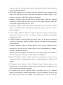
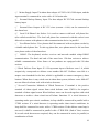
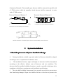
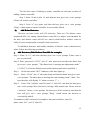
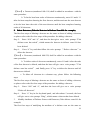
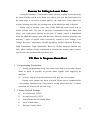
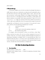
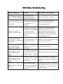
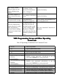
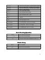
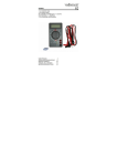
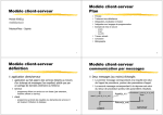
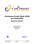
HB-G100 Series
User Manual for Intelligent
Burglar Alarm Host
Ningbo Saferhome Electronics Co., Ltd.
We are honoured that you have chosen our security products.
Thanks for your wise selection. To make full use of its performance
and ensure stable operation of the host, please carefully read this
User Manual before operating the host. For any questions, please
don
don’’t hesitate to consult our Customer Service Department or
agents.
Table of Contents
I.
Definition............................................................................2
II. Operating Precautions..........................................................4
III. Main Characteristics and Functions...................................4
IV. Name and Usage of Main Components..............................6
V.
System Installation.............................................................11
VI. Operating Instructions......................................................12
VII. How to Program Alarm Host.............................................18
VIII. Add/Delete Detectors and Remote Controllers................27
IX. Main Technical Specifications.........................................30
X.
XI.
Standard Configuration List..............................................31
Lists of Optional Parts....................................................31
XII. Failure Troubleshooting.....................................................32
XIII. Programming Set-up and Other Operating Commands....33
1
Introduction
HB-G100 Series Intelligent Burglar Alarm Host is an intelligent long-range
wireless transmission alarm system. This system adopts advanced microprocessor as
control core and has voice prompts, easy to install and operate. It can learn codes of
5 remote controllers and 120 HB-T001 Series solar-powered wireless active infrared
detectors, all of which constitute a complete long-range wireless alarm service
system. Defense zones 1-8 are mixed wired/wireless defense zones, and defense
zone 1 (numbered 000) is a tamper zone intended for the host. When a transmitting
detector is triggered in certain zone, it will transmit alarm information immediately
to the alarm host via wireless technology. After receiving alarm information, the host
will give out an alarm sound, and display defense zone number and dial pre-set
telephone numbers. Besides, this system can also perform remote control over the
host via phone to arm/disarm the host. This system requires no wires and covers a
large defense area, which is widely applied in workshops, enterprises and business
units, schools and other large and medium-scale places.
I. Definition
Arm
It refers to the state (also called alert state) in which the system can receive
any alarm signal.
Disarm It refers to the state (alert deactivation state) in which the system can not
receive any common alarm signal.
Defense Zone
It refers to the zone which is guarded by a detector which generates
an alarm input signal that can trigger the alarm system. This signal can be wired or
wireless.
Emergency Defense Zone
It refers to the zone in which the system can receive an
alarm input signal in any state. It is also called 24-hour defense zone.
Doorbell Defense Zone
It refers to the zone in which the host only gives out
doorbell “Ding- Dong” for 5 seconds and then stops giving out sounds, and the
indicator lamp works in the same way in arm/disarm state.
Shielded Defense Zone
It refers to the zone (not including emergency defense
2
zone) in which the host can receive shielded signals, and can not receive any alarm
signal temporarily.
Full Arm
It refers to the state in which all alarm detectors in full arming zone or
part arming zone enter into alert state.
Partial Arm
It refers to the state in which all alarm detectors in part arming zone
enter into alert state.
User Password It refers to the password through which user can arm/disarm
zones.
Set-up Password
It refers to the password used for user set-up.
Entry Time After receiving alarm information, user alarm host does not alarm
immediately, and after a period of time, it will alarm. This period of time is called
entry time or delayed alarm time.
Leaving Time After receiving arming command, user alarm host does not enter into
arming mode immediately, and after a period of time, it will enter into arming mode.
This period of time is called leaving time or delayed arming time.
Ringing Times
It refers to times of ringing the phone when users dial a fixed
phone number or SIM card number connected to the host for remote set-up.
Dialling Times
It refers to times of dialling preset user phone numbers when the
host gives out an alarm in fixed phone alarm mode or mobile phone alarm mode.
Siren Duration
After triggering on-the-spot alarm, the alarm host begins to
count immediately. Once the preset period of time expires, the alarm host will stop
alarming, and terminate transmitting alarm output signal. This preset period of time
is called siren duration.
Phone Alarm Mode
It refers to the mode in which user alarm host can
automatically dial pre-set informed telephone numbers when an alarm occurs, users
can arm/disarm the host through the alarm receiving phone, and the alarm host can
automatically check whether phone line is cut off.
On-site Alarm Mode
It refers to the mode in which user alarm host can neither
automatically dial alarm phones nor check if phone line is cut off, but can alarm on
the spot.
3
II. Operating Precautions
�
Please carefully read this User Manual and pay more attention to labels and
directions on the alarm host before operation. Check whether all wire
connections are correct and then turn the host on so as to avoid any damage to
the host.
�
The alarm host has no explosion-proof function, which cannot be directly
installed in Class I, II or III hazardous locations (i.e. locations where ignitable
concentration of flammable, explosive vapor/gas, dust or fiber exists),
otherwise, it may cause any hazard.
�
Please don’t disassemble the alarm host at will so as not to cause accidents or
damage the apparatus.
�
If failure occurs during operation, please hold the warranty card to approach
our client service centre or agents timely.
�
Please periodically perform test to identify and debug failures in time so as to
avoid system failure.
III. Main Characteristics and Functions
�
The wireless defense zone can automatically learn code with remote control.
And it is easy and fast to expand system capacity. There are 120 defense zones
in total, which are numbered 000-119 respectively. Each defense zone can
learn code with a detector. Defense zones 1-8(numbered 000-007)are mixed
wired/wireless defense zones, and defense zone 1(numbered 000)is a tamper
zone intended for the host.
�
Using password authentication for set-up ensures stable and reliable operation.
Voice prompt makes it real easy to use.
�
Each detector can be used to serve fully armed zone, partially armed zone,
emergency zone, doorbell zone and shielded zone according to user
requirements.
�
The system can preset 2 groups of telephone numbers for informing users of
4
security threats and 2 groups of telephone numbers of the alarm receiving
centre. The telephone numbers of the alarm receiving centre must be fixed
telephone numbers, which can be dialled preferably when an alarm is triggered
under telephone alarm mode.
�
�
Alarm or failure information can be displayed on the digital display.
The dialling times can be set.
�
External 12V backup battery input.
�
Call Pickup: Whether or not telephones connected with the alarm are busy, the
alarm host will take up the line and send alarm information to users in an
accurate and timely way.
�
Compatible with dual-tone multi-frequency signaling, it can dial 14-digit
telephone numbers.
�
It can get access to any pre-set telephone number and can set monitoring,
arming, disarming and on-the-spot-alarm by entering user password.
�
The alarm information of any detector can be memorized, and the alarm
information stored in the host can be erased once the relevant defense zone is
rearmed or the host is reset.
�
It can prerecord a 3-second voice message, so automatic voice responds to the
alarm when an alarm occurs.
�
Entry time, leaving time and alarm sound duration can be set.
�
There is sound prompt or LED indication when telephone line is cut-off, alarm
host or detector is under low power, the system is subject to strong light
interference.
�
DC 12V/0.5A alarm output is provided to connect the siren or control other
devices.
�
All settings can be stored in a memory unit, so they can not be lost when power
failure occurs.
5
IV. Name and Usage of Main Components
Keyboard Panel
1、Keyboard
1) “RUN” Indicator: “RUN” Indicator blinks when the keyboard is connected to the
host, which means the keyboard is well connected with the host.
2) “SET”Indicator: When “SET”Indicator lights up, that means the host is getting into
set-up mode. A correct password is required for entering into set-up mode. In this
mode, users can modify alarm mode and alarm time, and set alarm informed
telephone numbers etc.
3) “SIGNAL” Indicator: When “SIGNAL” Indicator lights up, that means the host is
getting into learning mode. In this mode, users can add/delete wireless detectors, or
modify attributes of defense zones, but can not receive alarm signals.
4) “FULL ARM” Indicator: When “FULL ARM” Indicator lights up, that means the
host gets ready for receiving alarm signals from all defense zones within the system
and giving out alarm.
5) “PA RT ARM” Indicator: When “PA RT ARM” Indicator lights up, that means the
6
host gets ready for receiving alarm signals from partially armed zones within the
system and giving out alarm.
6) “RECORD” Indicator: In set-up mode, users can prerecord a voice message to play
back at the time when a call is answered to respond to an alarm. When a voice
message is recorded, “RECORD” Indicator will light up.
7) “SHIELD ” Indicator: When the host receives shielded signals, “SHIELD ” Indicator
will light up, which means the host can not receive any alarm signal in a short time
except alarm signals from emergency zones.
8) “ALARM” Indicator: When any detector connected to the host sends an alarm
signal, “ALARM” Indicator will light up, and display defense zone No. where an
alarm is triggered.
9) “Low Voltage ” Indicator: When the voltage of the built-in battery of any detector
connected to the host is too low, “Low Voltage ” Indicator will light up and display
the defense zone No.
10) “Battery Damage” Indicator: When the built-in battery of any detector connected
to the host is damaged, “Battery Damage” Indicator will light up and display the
defense zone No.
11) “Invalid” Indicator: When any infrared detector (active wireless infrared detector)
connected to the host can not work properly due to non-calibration or damage,
“Invalid” Indicator will light up.
When any detector (magnetic door detector) can not work properly due to failure to
close for a long time or damage, “Invalid” Indicator will light up.
12)“Light Disturbance” Indicator: When any detector connected to the host can not
work properly due to strong light disturbance, “Light Disturbance” Indicator will
light up.
13) “Telephone Alarm” Indicator: When “Telephone Alarm” Indicator lights up, that
means the host is armed under telephone alarm mode. When an alarm occurs, the
host will dial alarm informed telephones.
14) “Telephone Line Cut-off” Indicator: When “Telephone Line Cut-off” Indicator
lights up, that means the external telephone line is not well connected or cut off, and
the system will give out voice prompt “The telephone line is cut off” once per
7
minute.
15) “Emergency Zone” Indicator: “Emergency Zone” Indicator will light up only when
set-up is performed for an emergency zone. Once emergency zone set-up is
completed, the indicator is not turned on even when an alarm occurs.
16) “Doorbell Zone” Indicator: “Doorbell Zone” Indicator will light up when set-up is
performed for a doorbell zone. Once doorbell zone set-up is completed, the indicator
is not turned on even when an alarm occurs.
17) 0~9 Number Key: 0~9 Number Key is used to enter parameters and password
when the alarm host is under set-up mode or signal learning mode.
18) #:“##”key acts as “ENTER” key or is used for confirmation.
19) *: Set attribute of defense zone
20) F1 Key: F1 key acts as“Partial Arm”key. Press F1 key to enter into“Partial Arm”
mode. Note: If the host is under“Full Arm”mode, disarm the host and then press F1
key to enter into“Partial Arm”mode.
21) F2 Key: F2 key acts as“Full Arm”key. Press F2 key to enter into“Full Arm”mode.
22) F3 Key: F3 key acts as “Disarm” key. Press F3 key, and then the host will give the
prompt “Please enter user password”. Enter correct user password and then enter“#”
key to enter into disarm mode.
23) F4 Key:: F4 key acts as “Emergency Alarm” key. Press F4 key to trigger an alarm.
24) A, B, C Key: The functions of A and C keys are not defined temporarily. B key is
used for set-up of linkage module manufactured by our support company.
Installation & Wiring Diagram of Engineering Host (See
2、Installation
the Diagram Below)
8
Installation & Wiring Diagram of Engineering Host
9
①
Mains Supply Input: The alarm host adopts AC 220V±10% 50Hz input, and the
input terminal is connected in series with a 0.5A fusion tube.
②
External Backup Battery Input: The host adopts DC12V7Ah external backup
battery input.
③
External Siren Output: A DC 12V siren (current: <0.6A) can be connected to
the alarm host.
④
Local Call Phone Line Socket: It is used to connect with local call phone line
(also called outside line). The local call phone line connected with this socket is not
allowed to connect with phone or other communication device in parallel.
⑤
User Phone Socket: User phones shall be connected with user phone socket by
a double-ended phone line. To take up phone line, user phones must be led out from
user phone socket of the alarm host.
⑥
RS485: The keyboard, wireless receiver and network module adopt RS485
communication. The head and end of line must have 120 ohm resistor to achieve
reliable communication. Note: Some of our products are equipped with 120 ohm
resistor.
⑦ Wired Defense Zone Input: Z1~Z8 represents input of defense zone 1-8, which
respectively corresponds to defense zone number 000~007. Defense zone 000 is a
tamper zone intended for the host, which is applicable to connect emergency alarm
buttons. When there is any wired zone in alarm host system, defense zones 000~007
are not allowed to learn code with wireless detectors.
⑧ Several Connection Methods of Wired Detectors: Z terminal is the positive
terminal of alarm signal return from wired defense zone. GND is the negative
terminal of alarm signal return. Wired defense zones can be used together with wired
detectors to achieve short circuit/cut-off alarm functions. If a wired detector is
operating under open circuit conditions, its loop shall be connected in parallel with a
2.7KΩ resistor. If a wired detector is operating under short circuit conditions, its
loop shall be connected in series with a 2.7KΩ resistor. If the defense zone loop is
not used, it shall be connected in parallel with a 2.7KΩ EOL (End of Line) resistor.
If several wired detectors are required, they can be connected in series, in parallel, or
combination of both.
10
Connection Principle: The normally open detector shall be connected in parallel with
a 2.7KΩ resistor, while the normally closed detector shall be connected in series
with a 2.7KΩ resistor.
Detector1 Detector2 Detector 3
Detector1 Detector2 Detector 3
B
B
C
C
2.7k
2.7k
Connection of several normally open detectors
Connection of several normally closed detectors
Mixed connection of normally open detectors and normally closed detectors
V. System Installation
1. Basic Requirements of System Installation Design
①
During installation, suitable types and models of detectors should be adopted
according to user ’s requirements for defense areas.
②
The installation location, angle and height of detectors shall be determined
according to the effective defense zone of detectors and site conditions. The
detectors shall be installed in hidden locations as much as possible which must be in
compliance with defense requirements and installation specifications.
③
The wire shall be hidden from normal view as much as possible to prevent trace
wire from being damaged. Open wire shall be fed into a wire duct to prevent wire
11
from damaged by mouse or other rodents.
④ The type and specification of detectors and cables in each defense zone should be
labeled on construction drawings (The usage of each wire within a cable shall be
marked).
⑤ All construction drawings should be archived for facilitating maintenance of the
host system.
2. System Installation and Debugging
Installation of Alarm Host
— —The alarm host shall be installed in a hidden position, and its external siren
shall not be covered with any materials to ensure an audible alarm sound.
— — The alarm host has no explosion-proof function, which cannot be directly
installed in Class I, II or III hazardous locations (i.e. locations where ignitable
concentration of flammable, explosive vapor/gas, dust or fiber exists), otherwise, it
may cause any hazard.
——The alarm host shall not be close to devices with high electromagnetic radiation
such as TV, air conditioner, computer and microwave oven to avoid influencing
receiving effect.
— — To ensure reliable operation of the alarm host, DC12V7Ah battery is
recommended as backup power if power failure often occurs or power failure takes a
long time in some areas.
——To get good receiving effect, please fully stretch out the receiving antenna.
VI. How to Add/Delete Remote Controllers and Detectors
This alarm host adopts code matching technology to add detectors and remote
control. The host can learn codes with 5 remote controllers and 120 detectors. There
are 120 defense zones in total, among which defense zone 000 is a tamper zone
12
intended for the host, and defense zones 000-007 are mixed wired/wireless defense
zones in which it is not recommended to install wireless detectors.
(I)
Add/Delete Remote Controllers
The host can learn codes with 5 remote controllers, which are numbered 10,
11,12,13,14 respectively.
To add/delete remote controllers, please follow the following procedures:
1. Add Remote Controller (Take Remote Controller 10 for example)
Step 1: Enter “# # #”, and then the alarm host gives out a voice prompt
that
“Please enter a pre-set password”.
Step 2: Enter password “112233” and “#” after password, and then the alarm host
gives out a voice prompt that
“The alarm host is entering into adjustment mode”
(“112233” is a factory default password for the host and can be modified. ).
Step 3:
Set the host when the “SET” indicator of the host lights up.
Step 4:
Enter “12*48 ” and “#” after password, and then the alarm host gives out a
voice prompt “The alarm host is entering into code learning mode” (Note: The
host interface will display “b” when you enter “*”. ).
Step 5:
Enter “10” (remote controller No.) and “#” after 10, and then the host gives
out a voice prompt “Press remote controller “ARM”key ”.
Step 6:
Press remote controller “Full Arm” key, and then the host gives a voice
prompt “Ding”, which means the host have successfully learnt code with the
remote controller.
“Full Arm” Key: Press “Full Arm” key to enter into “Full Arm” mode. The
function of “Full Arm” key is the same as that of F2 shortcut key on the keyboard
13
panel of the host.
“Disarm” Key: Press “Disarm” key to disarm the host (except for shielded zone,
doorbell zone and emergency zone). The function of “Disarm” key is the same as
that of F3 shortcut key on the keyboard panel of the host.
Emergency Key: Press Emergency Key to activate emergency alarm whether the
host is in Arm mode or Disarm mode. The function of Emergency Key is the same
as that of F4 shortcut key on the keyboard panel of the host.
“Partial Arm” Key: Press “Partial Arm” key to enter into “Partial Arm” mode.
The function of “Partial Arm” key is the same as that of F1 shortcut key on the
keyboard panel of the host.
【 Note 】 a. Remote controllers shall be added in accordance with the same
procedure.
b. To let the host learn codes of remote controllers continuously, enter 11
and # after 11 when the host completes learning the code of the first remote
controller, and then press “Arm” key to let the host learn the code of the next remote
controller until the host completes learning codes of all remote controllers.
2. Delete Remote Controllers (Take Remote Controller 10 for example
example))
The first five steps of deleting a remote controller are the same as those of adding a
remote controller.
Step 6:
Press “#” key again, and the host gives out a voice prompt “Ding”,
which means a remote controller is successfully deleted.
【Note】a. Remote controllers which have been added can be deleted in accordance
with the same procedure.
b. To let the host delete codes of remote controllers continuously, enter 11 and
# after 11 when the host deletes the code of the first remote controller, and then press
“#” key to let the host delete the code of the next remote controller until the host
deletes codes of all remote controllers.
c. To delete all remote controllers in a shortcut way, please follow the
following steps:
14
The first four steps of deleting a remote controller are the same as those of
adding a remote controller.
Step 5: Enter 19 and # after 19, and then the host gives out a voice prompt
“Delete all remote controllers”.
Step 6: Press “#” key again, and then the host gives out a voice prompt
“Ding”, which means a remote controller is successfully deleted.
(I)
Add/Delete Detectors
The host can learn codes with 120 detectors. There are 120 defense zones
(numbered 000-119), among which defense zone 000 is a tamper zone intended for
the host, and defense zones 000-007 are mixed wired/wireless defense zones in
which it is not recommended to install wireless detectors.
To add/delete detectors and modify attributes of defense zones with detectors,
please follow the following procedures:
1.
Add Detectors (Take Defense Zone 010 for example)
Step 1: Enter “# # #”, and then the host gives out a voice prompt “Please enter a
pre-set password”.
Step 2: Enter password “112233” and “#” after password, and then the alarm host
gives out a voice prompt“The alarm host is entering into adjustment mode”
(“112233” is a factory default password for the host and can be modified. ).
Step 3:
Set the host when “SET” indicator of the host lights up.
Step 4:
Enter “12*48 ” and “#” after password, and then the alarm host gives out a
voice prompt “The alarm host is entering into code learning mode” (Note: The
host interface will display “b” when you enter “*”. ).
Step 5:
Enter “010” (defense zone No.) and “#” after 010, and then the host gives
out a voice prompt “Now, the host is serving a fully armed zone. Please activate
a detector” (After a voice prompt, the detector will be activated, and then the
host will give out a voice prompt “Ding”, which means the detector is
successfully added).
To continue to add a detector, for example a detector for defense zone 011,
please enter “011” and “#” after 011.
15
【Note】 a. Detectors (numbered 000-119) shall be added in accordance with the
same procedure.
b. To let the host learn codes of detectors continuously, enter 011 and # 11
after the host completes learning the first detector, and then activate the next detector
to let the host learn the code of the next detector until the host completes learning
codes of all detectors.
2. Delete Detectors (Take the Detector in Defense Zone 010 for example)
The first four steps of deleting a detector are the same as those of adding a detector,
so please refer to the first four steps of the procedure for adding a detector.
Step 5:
Enter “010” and “#”, and then the host gives out a voice prompt “This
defense zone has exited”, which means the detector in defense zone 010 has
been deleted.
Press “#” key and then follow the voice prompt “Delete a detector”to
Step 6:
delete the detector.
【Note 】 a. Detectors (numbered 000-559) shall be added in accordance with the
same procedure.
b. To delete codes of detectors continuously, enter 011 and # after the code
of the first detector is deleted, and then the host will give out a voice prompt“This
defense zone has exited”, and finally press “#” key to delete the detector until all
detectors are deleted.
c. To delete all detectors in a shortcut way, please follow the following
steps:
The first four steps of deleting a detector are the same as those of adding a detector,
so please refer to the first four steps of the procedure for adding a detector.
Step 5:
Enter “909” and “#”, and then the host will give out a voice prompt
“Delete all detectors”.
Step 6:
Press “#” key in the keyboard panel, and after about 5 seconds, the host
will give out a voice prompt “Ding”, which means a detector has been deleted.
3.
Modify Attributes of Defense Zones with Detectors (Take defense zone 010 for
example)
The first four steps of modifying the attribute of a defense zone are the same as
16
those of adding a detector, so please refer to the first four steps of the procedure for
adding a detector.
Step 5:
Enter “010” and “*”, and then the host will give out a voice prompt “Now,
the host is serving a fully armed zone. Please enter the attribute of the defense
zone”(The attribute of all defense zones is set to“Fully Armed Zone”as default.
To modify the attribute of defense zone 010 from doorbell zone to fully armed
zone, enter “010” and “*”, and then the host will give out a voice prompt “The
host is serving a doorbell zone now. Please enter the attribute of the defense
zone”. ).
Step 6:
Enter“4” and “#”, and then the host will give out a voice prompt “Now,
the host is serving a doorbell zone” (1# fully armed zone, 2# partially armed
zone, 3# emergency zone, 4# doorbell zone, 5# shielded zone ).
【Note】a. The attributes of other defense zones shall be modified in accordance
with the same procedure.
b. To modify the attributes of defense zones continuously, enter 011* after
theattribute of the first defense zone is modified, and then the host will give out
avoice prompt “The host is serving a fully armed zone now. Pleaseenter the attribute
of the defense zone” (1# fully armed zone, 2# partially armed zone, 3# emergency
zone, 4# shielded zone, 5# doorbell zone).
Precautions
1.
Each wireless code (including remote control code and detector code) is not
learned twice by the same alarm host. For changing the first defense zone into the
second defense zone, delete the code for the first defense zone first.
2.
Once the remote control or detectors transmit alarm signals, the alarm host
will give out sound prompt, which signifies code learning is successfully
completed. After code learning is successfully completed, necessary recheck shall
be performed to check if code learning is successfully completed.
3.
If there is no correct operation for successive 30 minutes, the system will
automatically exit set-up mode.
17
Reasons for Failing to Learn Codes
Coding Redundancy: If the wireless code currently required to be learned by
the alarm host has exited in the alarm host, that is, this code has been learned by
the alarm host, it can not be learned again by the alarm host. If the alarm host
requires learning this code, the existing code in the alarm host shall be deleted.
Wrong type of wireless code: Any of the following cases would lead to
failure to learn code: The code of detectors is transmitted when the alarm host
learns code with remote control, or the code of remote control is transmitted
when the alarm host learns code with detectors. Besides, detectors generally can
transmit 7 types of special codes respectively related to Low Voltage, Low
Voltage Recovery, Anti-tamper, Invalid Operation, Invalid Operation Recovery,
Light Disturbance, Light Disturbance Recovery. Before detectors transmit any
code, please confirm if codes transmitted by detectors are normal codes, because
special codes are not learned by the alarm host.
VII. How to Program Alarm Host
1. Programming Precautions
①
During programming set-up, user alarm host shall be kept under disarm
mode as much as possible to prevent alarm signals from triggering an
interrupt.
②
At every step of set-up, the alarm host will give out voice prompt.
During voice prompt, any input is invalid. Please enter a command after
voice prompt. During set-up, if any input is wrong, please enter“0#” to cancel
operation and return to the previous step.
2. Factory Default Settings
1)
User Password: 123456
2)
Set-up Password: 112233
3)
Alarm Mode: On-site Alarm Mode
4)
Siren Volume: Max.
5)
Playing Content: Siren
18
6)
Dialling Times: 5
7)
Siren Duration: 30 minutes
8)
Leaving Time: 5 seconds
9)
Entry Time: 0 second
10)
Ringing Times Set via Remote Control: 9 times
11) Defense Zone Attribute: Full Arm
3. Detailed Programming Operation of Alarm Host
All programming operations below shall be performed in set-up mode.
The Procedure for Entering into Set-up Mode:
Step 1:
Enter “# # #” through the keyboard panel of the host
— — Users can hear a voice prompt “Please enter the preset password”, and the
“SET ”indicator lights up.
Step 2:
Enter A A A A A A # through the keyboard panel of the host
——The format of user password is AAAAAA, and the factory default password is
“112233”. If user password is correct, users can hear a voice prompt “The
alarm host is entering into adjustment mode”. And then users can continue with
the next step. If user password is wrong, the system will exit set-up mode, and
at the same time, the set-up indicator goes out.
Note: As mentioned above, the following programming operations shall be
performed after the host enters into set-up mode. If any error occurs during set-up,
enter 0# (the system gives out a voice prompt “Back”) to the previous step. Once
set-up is completed, enter 0 # 0 # to exit set-up mode (the system gives out voice
prompt “Back-Exit Set-up”).
1) Select Alarm Mode
①
Command Function: Telephone Alarm Mode
Command Grammar: 1 #
Function Description: This command enables the host to work under
telephone alarm mode and to cancel all alarm information displayed on the host.
Operating Steps: “###”(Please enter the preset password)+ “112233#”(The
host enters into adjusting mode)+“1#”(The host is fully armed,
and telephone alarm mode is activated).
19
②
Command Function: On-site Alarm Mode
Command Grammar: 3#
Function Description: This command enables the host to work under on-site
alarm mode in which the host can not dial any telephone and check outside line, as
well as to cancel all alarm information.
Operating Steps: “###”(Please enter the preset password)+ “112233#”(The
host enters into adjusting mode ) +“3#” ( The host is fully armed,
and on-site alarm mode is activated).
2) Local Disarm Mode
Command Function: Local Alarm
Command Grammar: 2#
Function Description: This command serves to disarm the host and exit SET
mode.
Operating Steps: “###”(Please enter the preset password)+ “112233#”(The host
enters into adjusting mode)+“2#”(Disarm the host).
3) Clear Failure Information
Command Function: Clear Failure Information
Command Grammar: 4#
Function Description: This command serves to clear failure information,
which is mainly applicable to manually clear troubleshooting information.
Operating Steps: “###”(Please enter the preset password)+ “112233#”(The
host enters into adjusting mode)+“4#” (Clear abnormal indication).
4) Command Function: Modify Preset Password
Command Grammar: 8 # A A A A A A # B B B B B B # B B B B B B #. “A A A
A A A” is a preset old 6-digit password, and “BBBBBB” is a new 6-digit password.
Once the preset old password is modified, the preset old password will be
automatically invalid. To enter into SET mode again, users must enter the new
password.
Operating Steps: “###”(Please enter the preset password)+“112233#”(The host
enters into adjusting mode)+“8#”(Please enter the preset password)+“112233#”
(Please enter a new password)+“BBBBBB#” (Please enter the new password
20
again)+“BBBBBB#”.
If you have forgotten the preset password indiscreetly, you shall contact our
customer service centre or your local distributor for help.
5) Command Function: Modify User Password
Command Grammar: 9 # A A A A A A # B B B B B B # B B B B B B #. “A A A
A A A” is an old 6-digit user password, and “B B B B B B” is a new 6-digit user
password. Once user password is modified, the old user password will be
automatically invalid. To enter into set-up mode again, users must enter the new
password.
Operating Steps: “###”(Please enter the preset password)+“112233#”(The
host enters into adjusting mode)+“8#”(Please enter user password)+“123456#”
( Please enter a new password ) +“BBBBBB#” ( Please enter the new password
again)+“BBBBBB#”.
If you have forgotten user password indiscreetly, you shall contact our
customer service centre or your local distributor for help.
4. How to Set Phone
① Command Function: Set Informed Phone Numbers
Operation Code: 2 groups of user phone numbers (fixed phone or cell phone)
represented by 10, 11 respectively can be set.
2 groups of phone numbers of the alarm receiving centre (fixed phone)
represented by 17, 18 respectively can be set (charge for access to 110
network).
Function Description: Set/delete informed phone numbers to ensure alarm information
can be transmitted by dialling the preset fixed phone numbers when the
host gives out an alarm.
【Note】If the informed phone numbers are local fixed phone numbers, a local area
code is not required for dialling informed phone numbers.
1.
Set Informed Phone Numbers
Fox example: Set the first group of informed user phone number
For the first two steps, please refer to the above mentioned procedure in SET mode.
21
Step 3:
Enter “10” (10 represents informed phone number) and “#”, and then the
host will give out a voice prompt “Please enter an informed phone
number”.
Step 4:
Enter a preset phone number and “#” to finish the set-up.
(If the input phone number is wrong, delete it and then enter a correct phone
number. For more details, please refer to “How to delete informed phone
numbers”. ).
【Note】a. To add the next group of phone number, please enter “11 #”, and then the
phone number and “#” until all informed phone numbers have been added (User
phone numbers are represented by 10 and 11 while the phone numbers of the alarm
receiving centre are represented by 17 and 18. ).
b. When an alarm occurs, the host will dial the phone numbers of the
alarm receiving centre preferably. The phones of the alarm receiving centre can only
be fixed phones.
2. Delete informed phone numbers
Fox example: Delete the first group of informed user phone number
For the first two steps, please refer to the above mentioned procedure in SET mode.
Step 3:
Enter “10” (10 represents informed phone number) and “#”, and then the
host will give out a voice prompt “Please enter an informed phone number”.
Step 4:
Press “#” key again, and then the host gives out a voice prompt“Ding”,
which means the informed phone number has been deleted.
【Note】a. All other informed phone numbers shall be deleted in accordance with the
above mentioned procedure (The informed user phone numbers are represented by
10 and 11 while the phone numbers of the alarm receiving centre are represented by
17 and 18.).
b. To delete informed phone numbers continuously, please enter 11 and # after
the first informed phone number is deleted, and then press “#” key when the host
gives out a voice prompt “Please enter the informed phone number” to delete the
informed phone number until all informed phone numbers are deleted.
c. To delete all informed phone numbers in a shortcut way, please follow the
following steps:
22
For the first two steps, please refer to the above mentioned procedure in SET mode.
Step 3: Enter 19 and #, and then the host will warn users through voice message to
delete all informed phone numbers”.
Step 4: Press “#” key again, and then the host will indicate a remote controller has
been successfully deleted.
② Command Function: Set Ringing Times by Remote Control
Function Description: “D D” is ringing times (05-15) set to determine when
the alarm host will enter into long distance set-up mode. “D D” must be a 2-digit
number. When ringing times reaches a pre-set value, the alarm host will enter into
long-distance set-up mode. Set-up shall be done according to long distance set-up
table.
Operating Steps: “###”( Please enter the preset password)+“112233#”(The
host enters into adjusting mode)+“37#”(Please enter ringing times)+“09#”(The
host gives out a voice prompt “Ding” to indicate ringing times has been successful
set up).
③ Command Function: Set Dialling Times
Function Description: “D D” is dialing cycle number (01-99) and must be a
2-digit number. Dialing cycle refers to a cycle during which the alarm host dials
phone numbers from first to last when an alarm occurs or the system reports the
alarm.
Operating Steps: “###”(Please enter the preset password)+“112233#”(The
host enters into adjusting mode)+“38#”(Please enter dialling times)+“05#”(The
host gives out a voice prompt “Ding” to indicate ringing times has been successful
set up).
5. Set Alarm Sound Volume
① Command Function: Select on-site alarm volume
Command Grammar: 2 4 # , 2 5 # , 2 6 # , 2 7 #
Function Description:
Press 2 4 # to select the small on-site alarm volume;
23
Press 2 5 # to select the medium on-site alarm volume;
Press 2 6 # to select the large on-site alarm volume
Press 2 7 # to select the maximum on-site alarm volume
Operating Steps: “###”(Please enter the preset password)+“112233#”(The host
enters into adjusting mode)+“27#”(for trial listening of alarm volume
of the host).
Note: Once this set-up is finished, the preset alarm volume will be automatically
modified.
② Command Function: Set on-site alarm volume to mute
Function Description: If on-site alarm volume is set to mute, in phone alarm
mode, the horn can not sound an alarm, and the alarm sound output
terminal can not output alarm sound, but informed user phone
numbers can be dialled to transmit alarm information, and a normal
prompt sound is given out when a remote controller is working, an
alarm occurs due to phone line cut-off, or the power supply voltage
is too low.
Note:
a. When alarm volume is set to any level in accordance with the last step, the
mute function will be automatically cancelled.
b. Mute alarm is only applicable to phone alarm mode, because there is no
mute function in on-site alarm mode.
6. Record
① Command Function: Record
Command Grammar: 3 0 # Record #
Function Description: Press 3 0 #, and then “ RECORD ” Indicator on the
keyboard panel lights up. Speak into the microphone built into the
alarm host cabinet to record your desired voice (Recording time is 2-3
seconds). The previously recorded voice message will be replaced by
newly recorded voice message, and the newly recorded content can be
stored permanently and is not lost when power supply is cut off.
24
② Command Function: Audition the Record
Command Grammar: 3 1 #
Function Description: Press 3 1 #, and then 2-3 seconds of record will be played
from the built-in speaker of the host.
7. Select Playing Content
① Command Function: Select playing the record
Command Grammar: 3 2 #
Function Description: After receiving an alarm call, you will hear the voice
message prerecorded in the host, and then you can follow the prompts to perform
other operations.
② Command Function: Select playing the siren
Command Grammar: 3 3 #
Function Description: After receiving an alarm call, you will hear the siren, and
then you can follow the prompts to perform other operations.
Note: When any function of ① and ② is selected, the other function will be
automatically invalid.
8. Set Various Time Parameters
① Command Function: Set siren duration
Command Grammar: 3 4 # D D #
Function Description: “D D” refers to siren duration (01-99 minutes) and must
be a 2-digit number. After the alarm host sounds an alarm, the system will
automatically turn off siren and disable siren output once siren duration reaches a
preset value, but the indicator in the defense zone where an alarm occurs is on
continuously until the defense zone is disarmed.
Operating Steps: “###”(Please enter the preset password)+“112233#”(The
host enters into adjusting mode)+“34#”(Please enter siren duration)+“10#”(The
host gives out a voice prompt “Ding” to indicate siren duration has been
successfully set up).
25
② Command Function: Set leaving time
Command Grammar: 3 5 # D D #
Function Description: “D D” refers to leaving time, also called delayed ARM
time and must be a 2-digit number (00-99 minutes). Within the leaving period of
time, the alarm host gives out a short “Beep” sound every 1 second, and you must
leave defense zones during the time period.
Operating Steps: “###”( Please enter the preset password)+“112233#”(The
host enters into adjusting mode)+“35#”(Please enter leaving time)+“05#”(The host
gives out a voice prompt “Ding” to indicate leaving time has been successfully set
up).
③ Command Function: Set Entry Time
Command Grammar: 3 6 # D D #
Function Description: “D D” refers to entry time, also called delayed alarm
time and must be a 2-digit number (00-99 seconds). If you break into an armed
defense zone, the alarm host does not sound an alarm when you disarm the defense
zone by remote control or phone for local calls within the entry period of time. If
you do not disarm the defense zone within the entry period of time, the alarm host
will automatically sound an alarm once the pre-set entry time expires. Within the
entry period of time, the alarm host gives out a “Beep” sound every 1 second.
Operating Steps: “###”(Please enter the preset password)+“112233#”(The
host enters into adjusting mode)+“36#”(Please enter entry time)+“00#”(The host
gives out a voice prompt “Ding” to indicate entry time has been successfully set up).
④ Command Function: Set ringing times
Command Grammar: 3 7 # D D #
Function Description: “D D” refers to ringing times (05-15) within which the
host can automatically pick up the call.
Operating Steps: “###”( Please enter the preset password)+“112233#”(The
host enters into adjusting mode)+“37#”(Please enter ringing times)+“09#”(The
host gives out a voice prompt “Ding” to indicate ringing times has been successfully
set up).
26
⑤ Command Function: Set dialling times
Command Grammar: 3 8 # D D #
Function Description: “D D” refers to dialing times (01-99), namely how
many times the host dials phone numbers according to a list of preset phone
numbers. Note: This set-up does not apply when the host dials phone numbers of the
alarm receiving centre.
Operating Steps: “###”( Please enter the preset password)+“112233#”(The
host enters into adjusting mode)+“38#”(Please enter dialling times)+“05#”(The
host gives out a voice prompt “Ding” to indicate dialling times has been successfully
set up).
9. Set Security ID
Command Grammar: 40 # D DDD #
Function Description: This alarm host will transmit alarm information to the
alarm receiving centre when an alarm is triggered under phone alarm mode. The
alarm host adopts Ademco Contact ID protocol to transmit information. XXXX is a
4-digit host ID set by users.
VIII. Operating Instructions
This host has two types of passwords, namely user password and set-up
password. User password is only used to arm/disarm the host, perform phone remote
control & monitoring, as well as play back siren and record. Set-up password
enables the host to enter into set-up/learning mode. Press ### + set-up password + #
to enter into set-up/learning mode.
1. Arm/Disarm
1. Arm/Disarm by external keyboard of the alarm host.
Press F1 key on the keyboard to enter into “Partial Arm” mode. Press F2 to
enter into enter into “Full Arm” mode. Note: You can switch from “Full Arm” mode
to “Partial Arm” mode by disarming the alarm host and then pressing F1 key. To
disarm the alarm host, please press F3 key and then enter the correct user password.
27
2. Modify Alarm Mode and Arm/Disarm in SET Mode
Enter # # # A A A A A A # to enter into set-up mode and modify alarm mode.
①
Arm the host in phone alarm mode
Enter 1 # to arm in phone alarm mode and exit set-up mode.
②
Arm in on-site alarm mode
Enter 3 # to arm in on-site alarm mode and exit set-up mode.
“A A A A A A ” refers to a 6-digit set-up password. The factory default set-up
password is “112233”. Once arm is completed, the host will automatically exit
set-up mode and is under leaving state. If leaving time is not set up, the host will
enter into arm mode immediately, and the indicator for the corresponding defense
zone and “ARM” indicator will light up.
③
Disarm
Enter 2 #, and then the host will automatically disarm.
This disarm operation does not cause detector alarm information and failure
information to be deleted.
Once the above mentioned arm/disarm operation is completed, the system will
automatically exit set-up mode.
3: Arm/Disarm by Remote Control
Press the “Full Arm” key on the remote control, and then your alarm host will
indicate through voice prompts that you are entering into full arm mode.
Press the “Partial Arm” key on the remote control, and then your alarm host
will indicate through voice prompts that you are entering into partial arm mode.
Press the “Disarm” key on the remote control, and then your alarm host will
indicate through voice prompts that the host is being disarmed.
4: Remote arm/disarm by fixed phone or mobile phone
Please refer to relevant operation procedures in “Alarm Receiving Operation”
and “Remote Set-up”.
2. Alarm Operation
Anti-theft Operation:
Before you leave your residence or work place, please follow any of
28
arm/disarm methods in "Arm/Disarm Operation" to arm the alarm host and to ensure
the system is on alert.
The alarm host will automatically alarm according to the pre-set alarm
procedure as soon as someone breaks into a defense area.
Emergency Alarm (or Help)
If any emergency circumstance such as robbery occurs in your residence or
workplace, the system will enter into alarm mode whether the alarm host is in arm
mode or in disarm mode when pressing the “Emergency Button” key on the remote
control panel or pressing corresponding alarm switch.
Trigger the Alarm System in the Shielded Defense Zone
When any defense zone is set to shielded defense zone, if an alarm is triggered
in this zone, all defense zones except for emergency defense zones will be shielded,
and the alarm host does not sound an alarm when any alarm is triggered in other
defense zones.
3. Alarm Receiving Operation
In phone alarm mode, upon receipt of alarm call, you can hear a 5-second siren
or record after picking up the phone. At this time, users can selectively enter the
following commands through the phone keyboard:
1#
Arm (Set to Full Arm)
2#
Disarm
3#
Activate on-site siren at the maximum volume level
0#0#
Exit Alarm Receiving Mode
For example: Once receipt of alarm phone, you can hear 5-second siren or
record after picking up the phone. Enter 1 # through the keyboard of the alarm
receiving phone to rearm the host. Enter 2 # to exit on-site alarm mode to enter into
disarm mode in which other informed phone numbers can not dialed. Enter 3 # to
activate on-site siren at the maximum volume level. Enter 0 # 0 # to exit alarm
receiving mode, and then the alarm host will cut off phone line. If you can not
perform any valid operation within 30-second wait time, the alarm host will
automatically cut off phone line and then continue to dial other groups of informed
29
phone numbers.
4. Remote Set-up
Call the phone numbers pre-set for the user alarm host through fixed phone or
mobile phone in other areas, and then the user alarm host will automatically pick up
the phone after receiving several rings (program default: 9 times ) and at the same
time you can hear a voice prompt “Welcome to Use Hengbo Security Product”. And
then you can enter # # # through the keyboard of fixed phone or mobile phone, and
then you can hear a voice prompt “Please enter user password”. Enter A A A A A A #.
“A A A A A A ” is a 6-digit user password (The factory default user password is
123456, which can be modified by users). If user password is wrong, the system will
automatically cut off phone line and exit set-up mode. If user password is correct,
please selectively enter the following commands after 30 seconds.
1#
Arm (Set to Full Arm)
2#
Disarm
3#
0#0#
Activate on-site siren at the maximum volume level
Exit Alarm Receiving Mode
For example: Once user password is correct, you will hear a short “Beep”
prompt, and then the system will wait for receiving commands in the next 30
seconds. At this time, you can enter operating commands through the keyboard of a
long-distance fixed phone or cell phone. Enter 1 # to arm the alarm host. Enter 2 # to
disarm the alarm host. Enter 3 # to activate on-site siren immediately. Enter 0 # 0 #
to exit set-up mode. If users can not perform any valid operation within 30-second
wait time, the alarm host will automatically cut off phone line.
IX. Main Technical Specifications
1.
User Alarm Host
Operating Voltage: AC220V±10%
50Hz
Operating Current: Standby Current: ≤100mA (for connecting a keyboard), Alarm
Current: ≤350mA
30
Operating Conditions: -10-55℃
Relative Humidity: 40-70%
Dial Mode: Double Audio Frequency High Frequency Group Level: -7±2dBm
Low Frequency Group Level: -9±2dBm
Pick-up Resistance: ≤300Ω
External Backup Battery: DC12V7Ah
Dimension: 265×260×80(mm)
2.
Wireless Remote Controller
Operating Voltage: 12V 27mA
Standby Current: ≤ 5uA
Alarm Current: ≤13.5mA
Transmitting Power: ≥10 mW
Dimension: 35×61×14(mm)
X. Standard Configuration List
Standard Configuration List of Alarm Host
User Manual
1
Warranty Card
User Alarm Host
1
2.7K End-of-Line Resistor
External Keyboard 1
Rod Antenna
1
8
1
XI. List of Optional Parts
1.
Solar-Powered Active Infrared Detector
2.
Wireless Passive Infrared Detector
3.
Wireless Remote Controller
4.
Lead Battery 12V7Ah
5. Network Commutation Module (HB-WT-1)
6. Linkage Module(HB-LD-120)
31
XII. Failure Troubleshooting
Failure Symptom
Reason
Power plug is not
“RUN” Indicator does not
properly connected, or
light up when powered on
socket has no power
Failure Recovery Method
Check power plug or socket
Enter correct user password or
User password is wrong,
The host fails to enter into
contact local distributor for
or is modified or
set-up mode
recovering password.
forgotten.
Telephone extension should be
Outside line is connected
connected in parallel with the
in parallel with telephone
The alarm host dials
telephone output terminal of the
extension or phone
wrongly when alarming.
alarm host, or enter correct code
without internet access is
back to phone arm mode through
adopted.
standard phone device.
The end of line resistors
The alarm host alarms
of the alarm host are not Install end of line resistors according
immediately when powered
installed or become
to operating instructions.
on or armed.
loose.
LED “Invalid” Indicator
The detector for this
lights up and displays
defense zone is not
Re-calibrate the detector.
defense zone number.
calibrated.
LED “Low Power”
The voltage of the battery
Indicator lights up and
of the detector for this
Replace the battery of the detector.
displays defense zone
defense zone is too low.
number.
LED “Light Interference”
The detector for this zone Check if the detector is properly
Indicator lights up and
is subject to strong light installed and adjust the installation
displays defense zone
interference.
location.
number
In phone alarm mode,
Check phone line for local calls to
“Phone Cut-off” indicator phone line for local calls
ensure the line is well connected, or
lights up.
is not well connected or
replace the line.
is cut off.
32
LED “Power Failure”
indicator lights up and
displays defense zone
number.
The remote distance of
remote control becomes
shorter.
User password is wrong.
When the ringing times
reaches the pre-set value
under long-distance
operation mode, dialling
sound can be heard from
the phone.
The battery of the
detector for this defense Replace the battery
zone is damaged.
The voltage of the battery
Replace the battery
is low.
User password is
modified or forgotten.
The phone picked up by
the alarm host has an
anti-theft switch, so the
system wrongly judges
the phone is illegally
used when the alarm host
simulates picking up the
phone.
Please contact local distributor for
recovering password.
Close the “Anti-theft” function of
the phone.
XIII. Programming Set-up and Other Operating
Commands
List of Operating Commands for Common Users
0#0#
1#
2#
3#
4#
8# A A A A A A # B B B
BBB#
BBBBBB#
9 #AAAAAA # B BB
BBB#
BBBBBB#
10#CCCCCC#
11#CCCCCC#
12#CCCCCC#
13#CCCCCC#
10##
Exit set-up mode
Arm in phone alarm mode
Disarm
Arm in on-site alarm mode
Clear all failure information
Modify set-up password (AAAAAA is an old
password; BBBBBB is a new password)
Modify user password (AAAAAA is an old
password; BBBBBB is a new password)
Add the first group of informed phone numbers
Add the second group of informed phone numbers
Add the third group of informed phone numbers
Add the fourth group of informed phone numbers
Delete the first group of informed phone numbers
33
11##
Delete the second group of informed phone numbers
Delete the third group of informed phone numbers
Delete the fourth group of informed phone numbers
Delete all phone numbers
Select small alarm volume
Select medium alarm volume
Select large alarm volume
Select maximum alarm volume
Select mute alarm
Record
Playback
Select playing the record
Select playing the siren
Set siren duration(DD=01-99 seconds)
Set leaving time(DD=01-99 seconds)
Set entry time(DD=01-99 seconds)
Set ringing times in other areas (DD=05-15 times)
Set dialling times (DD=03-99 times)
Set the host ID
12##
13##
19##
24#
25#
26#
27#
28#
30#
31#
32#
33#
34#DD#
35#DD#
36#DD#
37#DD#
38#DD#
40# D D #
Alarm Receiving Operation
0 # 0#
1#
2#
3#
Exit alarm receiving mode
Arm the host immediately
Disarm the host immediately
Activate on-site siren at maximum volume level
Remote Set-up
0#0#
1#
2#
3#
Exit set-up mode
Arm the host immediately
Disarm the host immediately
Activate on-site siren at maximum volume level
34
Warning: Limits of This Security System
As an advanced hi-tech anti-theft system, although this product can reduce and
prevent the occurrence of theft, robbery and fire and thus reduce loss, we can not
guarantee no above-mentioned accidents happen or no personal casualty and
property loss happens.
And we invite you to understand that any alarm system, whether it is used for
business or home use, may wrongly alarm or fail to alarm because of different
reasons. Therefore, we remind you to pay attention to the following possible
reasons:
1.
2.
The system is not arme d becaus e of carelessnes s.
Users or installation personnel’s misunderstanding of user manual or
improper operation may result in system failure .
3.
An intruder intrudes the place where is beyond the defense areas or has
technical capacity to pass by the alarm detector or make it malfunction. The passive
infrared detector can only detect an intruder breaking into any area mentioned in
Detector Installation Instructions, but can not detect a body in motion or intruder
behind walls, inside ceilings, floor, as well as behind closed doors, glass partition
walls, glass doors or glass windows. Users shall select a suitable detector according
to different security requirements.
4.
The detection sensitivity of passive infrared detectors can automatically vary
according to ambient temperature. When the ambient temperature of defense areas
exceeds 32 ℃, the detection performance of infrared detectors (detection distance)
will reduce as ambient temperature rises. It is recommended to carefully check its
operating status of this detector under ambient temperature to confirm if the detector
operates according to safety precautions. If necessary, reasonable adjustment shall
be done.
5.
There is no power supply, or the battery has aged or is damaged.
6.
The alarm siren is installed at the other side of the closed door, so it may not be
able to warn people or wake up the sleeper.
7.
There is something wrong with telephone line which transmits alarm signals to
35
the alarm center, or other lines are busy, so that alarm information can not be
transmitted in time.
8.
The alarm system does not alarm when someone intrudes or there is an
emergency alarm. The most common reason is that the alarm system does not get
properly maintained. Like other electrical equipments, this equipment may be
subject to electronic component damage. Therefore, users shall routinely check and
maintain the system.
9.
Other Unpredicted Reasons.
If you do not agree to the above-mentioned terms, you can return the product to us
within 3 days from purchase date provided no man-made damage occurs, and we
will refund you all money. Otherwise, you will be deemed to have agreed to the
above-mentioned terms.
User Warning: The alarm equipment can not substitute for insurance, so you
must be careful to insure your life and property.
This user manual is subject to our interpretation and all functions are subject
to change without notice.
36