1
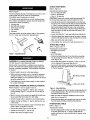
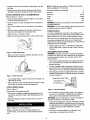
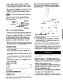
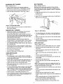
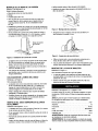
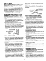
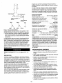
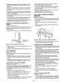
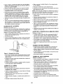
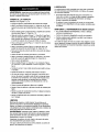
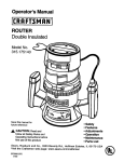
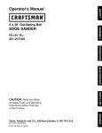
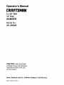
Operator's Manual
CRRFT$IRN o
6 x 48" Belt
12" Disc
SANDER
Model No.
351.226060
CAUTION: Read and follow
all Safety Rules and Operating
Instructions before First Use
of this Product.
Sears, Roebuck and Co., Hoffman Estates, IL 60179 U.S.A.
2643.01 Draft (01/12/01)
Warranty .......................................
Safety Rules ....................................
2
2
Unpacking
3
.....................................
Assembly .....................................
Installation ....................................
3-4
4-5
Operation ....................................
Maintenance ....................................
5-8
8
• Proper electrical receptacle should be available for toot.
Three prong plug should be plugged directly into properly
grounded, three-prong receptacle.
• Extension cords should have a grounding prong and the three
wires of the extension cord should be of the correct gauge.
• Keep visitors at a safe distance from work area.
• Keep children out of workplace. Make workshop childproof.
Use padlocks, master switches or remove switch keys to
prevent any unintentional use of power tools.
Troubleshooting .................................
Parts iflustration and List .......................
9
16-13
TOOL
SHOULD
BE MAINTAINED
Espafiol ....................................
14-23
• Consult manual for specific maintaining
procedures.
• Always unplug tool prior to inspection.
and adjusting
• Keep tool lubricated and clean for safest operation.
• Remove adjusting tools. Form habit of checking to see that
adjusting tools are removed before switching machine on.
FULL ONE YEAR WARRANTY ON CRAFTSMAN
BELT & DISC SANDER
• Keep all parts in working order. Check to determine that the
guard or other parts will operate properly and perform their
intended function.
If within one full year from the date of purchase, this
Craftsman sander fails due to a defect in material or workmanship, Sears will repair it free of charge. Warranty service
is available by contacting Sears in-home major brand repair
service.This warranty gives you specific legal rights and you
may also have other rights which vary from state to state.
• Check for damaged parts. Check for alignment of moving
parts, binding, breakage, mounting and any other condition
that may affect a tool's operation.
If this sander is used for commercial purposes, this warranty
applies for only 90 days from the date of purchase.
• A guard or ether part that is damaged should be properly
repaired or replaced. Do not perform makeshift repairs,
(Use parts list provided to order replacement parts.)
Sears, Roebuck and Co., Dept. 817WA, Hoffman Estates, IL
60179
KNOW
HOW TO USE TOOL
• Use right tool for job. Do not force tool or attachment to do
a job for which it was not designed.
• Disconnect tool when changing belt or abrasive disc.
WARNING:
For your own safety, read all of the instructions
and precautions before operating tool.
• Avoid accidental start-up. Make sure that the tool is in the
"OFF' position before plugging in.
CAUTION: Always follow proper operating procedures as
• Do not force tool. It will work most efficiently at the rate for
which it was designed.
defined in this manual even if you are familiar with use of this
or similar tools. Remember that being careless for even a
fraction of a second can result in severe personal injury.
• Keep hands away from moving parts and sanding surfaces.
• Never leave tool running unattended. Turn the power off
and do not leave tool until it comes to a complete stop.
BE PREPARED FOR JOB
• Wear proper apparel. Do not wear loose clothing, gloves,
neckties, rings, bracelets or other jewelry which may get
caught in moving parts of machine.
• Do not overreach. Keep proper footing and balance.
• Wear protective hair covering to contain long hair.
•
• Never stand on tool. Serious injury could occur if tool is
tipped or if belt or disc are unintentionally contacted.
• Wear safety shoes with non-slip soles.
Know your tool. Learn the tool's operation, application and
specific limitations.
• Use recommended accessories (refer to page 11). Use of
improper accessories may cause risk of injury to persons.
• Wear safety glasses complying with United States ANSI
Z87.1. Everyday glasses have only impact resistant lenses.
They are NOT safety glasses.
• Handle the workpiece correctly. Protect hands from possible injury.
• Wear face mask or dust mask if operation is dusty.
• Be alert and think clearly. Never operate power tools when
tired, intoxicated or when taking medications that cause
drowsiness.
• Turn machine off if it jams. Belt jams when it digs too
deeply into workpiece. (Motor force keeps it stuck in the
work.)
PREPARE WORK AREA FOR JOB
• Support workplace with miter gauge, belt platen or work
table.
• Keep work area clean. Cluttered work areas invite accidents.
•
• Do not use power tools in dangerous environments. Do not
use power tools in damp or wet locations. Do not expose
power tools to rain.
Maintain '/,," maximum clearance between table and sanding belt or disc.
CAUTION:
Think safety! Safety is a combination of operator
common sense and alertness at all times when tool is being
used.
• Work area should be properly lighted.
WARNING:
Do not attempt to operate tool until it is completely assembled according to the instructions.
2
ATTACH FOOT RESTS
Refer to Figure 12.
Refer to Figure 1.
Required parts and hardware:
• Four foot rests with bolts
Check for shipping damage. If damage has occurred, a claim
must be filled with carrier. Check for completeness.
Immediately report missing parts to dealer.
• Eight 5/_,,flat washers
• Four5/_,'-18 Hex nuts
CAUTION: Sander with cabinet weighs approximately 200
The sander comes assembled as one unit. Additional parts
which need to be fastened to sander, should be located and
accounted for before assembling.
A Abrasive disc
B Belt table with trunnion
Ibs. At least two people are requLred to attach foot rests.
• Carefully tip the sander to raise cabinet from the floor just
enough so that one foot rest with bolt and washer (Key Nos.
3, 4 and 5) can be positioned under the cabinet corner so
that the bolt slides through the hole on the cabinet base.
Slowly set the sander back to the floor. Repeat three more
times to position one foot rest with bolt under each of the
cabinet corner.
C Miter gauge assembly
D Two handles
E Workstop
Parts bag includes: 8mm flat washer, eight %_"fiat washers,
four '/_"-18 hex nuts and four foot rests with bolts.
• Loosen knob (Key No. 7) and open cabinet door (Key No. 8).
• Using the cabinet door opening, secure foot rests to cabinet
using four flat washers and four hex nuts (Key Nos. 2 and 3).
• Make sure all the hex nuts are tight.
A
• Close cabinet door and secure it with knob (Key No. 7),
ATTACH BELT TABLE
Refer to Figures 2 and 11.
Figure I - Unpacking
Required parts and hardware:
• Belt table with trunnion
• Handle
• 8mm Flat washer
Sander
• Position belt table (Key No. 63) on the belt housing (Key
No. 48) so that the trunnion (Key No. 18) travels on the
slide (Key No. 20).
CAUTION: Do not attempt assembly if parts are missing,
Use this manual to order replacement parts.
Before sander is assembled, a suitable location should be
chosen. The sander with cabinet weighs approximately 200
Ibs when completely assembled. They should be assembled
on location.
• Set the belt table position so that the 0° mark on the trunnion is aligned with the pointer (Key No. 54).
• Secure belt table position using the handle and flat washer
(Key Nos. 10 and 16), Tighten handle into the threaded hole
on the belt housing,
• Sander needs to be set on a flat, level surface.
• Make sure there is ample room for moving the workpiece
through the entire cut. There must be enough room that
neither the operator nor the bystanders will have to stand in
line while using the tool,
Belt Tension Handle
/
• Good lighting and correct power supply are also required
for a proper work area.
,_L.1..Table Lock Handle
ADJUST
BELT HOUSING
TO VERTICAL
POSITION
Refer to Figures 11 and 12, pages 10 and 12.
Figure 2 - Attach Belt Table
• Loosen one hex nut (Figure 11, Key No. 38) on the belt
housing casting (Figure 11, Key No, 48). Do not take out
hex nut.
• Sander is shipped with the belt tension handle (Key No. 52)
at the released position, Pull down the handle toward the
belt table to tension the belt.
• Move to the rear of the sander and gently lift the belt housing up supporting the housing from both sides,
• Make sure that the clearance between the belt and belt
table does not exceed '/16".
• Lift belt housing until it is adjusted to the vertical position.
• Wear protective glove and manually push the belt to verify
that belt travels smoothly and without interference.
• Tighten one hex nut (Figure 11, Key No. 38) from the rear
of the sander,
POSITION
DISC TABLE
• Move to the front of the sander; loosen and remove three
knobs (Figure 12, Key Noa. 7 and 27).
Refer to Figure 11.
•
Required part: Handle
Remove dust hood (Figure 12, Key No. 28).
• Sander is shipped with the disc table (Key No. 24) attached
to the disc guard (Key No. 11) using a handle with flat
washer one side and a hex head bolt with flat washer on the
other side,
• Tighten hex nut (Figure 11. Key No. 38).
• Replace dust hood and tighten knobs.
3
•
Loosen and remove hex head bolt and flat washer from the
disc table.
NOTE: Though the motor works at 115/230-volt AC, sander
must be operated at 115 volts only.
•
Replace hex head bolt with the handle provided. Secure
disc table to disc guard using the handle and fiat washer.
Horsepower (Maximum Developed) ...................
ATTACH
ABRASIVE
DISC TO ALUMINUM
DISC
Refer to Figures 3, 4 and 1t+
3
Amperes ......................................
15
Frequency ..................................
Phase .....................................
60 HZ
Single
• Sander is shipped with the abrasive (KeyNo. 5) not applied
to the aluminum disc (Key No. 1).
RPM .......................................
3450
Prewired ....................................
115V
• Clean the aluminum disc if necessary prior to applying the
abrasive.
WARNING:
All electrical connections must be performed by
a qualified electrician.
WARNING:
Do not connect sander to the power source until
all assembly steps have been completed.
• Remove the adhesive cover from the back of the abrasive
disc.
• Slide the abrasive between the disc table and aluminum
disc and center abrasive on the aluminum disc.
POWER
• Apply pressure on abrasive to paste.
The motor is designed for operation on the voltage and frequency specified. Normal loads will be handled safely on voltages not more than 10% above or below specified voltage.
• Make sure abrasive is pasted evenly on the aluminum disc.
SOURCE
Running the unit on voltages which are not within the range
may cause overheating and motor burn-out. Heavy loads
require that the voltage at motor terminals be no less than the
voltage specified on nameplate.
•
Power supply to the motor is controlled by a single pole
locking rocker switch. Remove the key to prevent unauthorized use.
GROUNDING
Figure 3 - Attach Abrasive Disc
INSTRUCTIONS
WARNING:
Improper connection of equipment grounding
conductor can result in the rLskof electrical shock, Equipment
should be grounded while in use to protect operator from
elect rioal shock,
• Make sure that the clearance between disc table and abrasive disc does not exceed 1/_,,
• Check with a qualified electrician if grounding instructions
are not understood or if in doubt as to whether the tool is
properly grounded.
• This tool is equipped with an approved 3-conductor cord
rated at 240V and a 3-prong grounding type plug rated at
125V (Figure 5) for your protection against shock hazards.
• Grounding plug should be plugged directly into a properly
installed and grounded 3-prong grounding-type receptacle,
as shown (Figure 5).
Figure 4 - Check Disc Table
•
Use a straight edge or square to check if the disc table is at
right angle to the disc.
ProP::Llyn
dGi
i ;u_ rdoendg
OutIet _._
• Wear a protective glove and manually turn the disc to verify
that the disc turns freely and without interference.
3 Prong Plug
ATTACH
MITER
GAUGE
Refer to Figure 11,
Figure 5 - 3-Prong Receptacle
Required part: Miter gauge assembly
•
• Do not remove or alter grounding prong in any manner. In
the event of a malfunction or breakdown, grounding provides a path of least resistance for electrical shock.
Miter gauge is shipped completely assembled (Key No. 9)
and can be used with the belt or disc tables (Key Nos. 63
and 24).
WARNING: Do not permit fingers to touch the terminals of
• Slide miter gauge bar (Key No. 76) into the slot on belt or
disc table.
plug when installing or removing from outlet.
• Plug must be plugged into matching outlet that is properly
installed and grounded in accordance with all local codes
and ordinances. Do not modify plug provided. If it will not fit
in outlet, have proper outlet installed by a qualified
electrician.
R_er to Figures 5, 6, and 7, pages 4-5.
Sander comes with the motor and wiring installed. The
115/230-volt AC universal motor has the following specifications.
•
4
Inspect tool cords periodically, and if damaged, have
repaired by an authorized service facility.
• Green (or green and yellow) conductor in cord is the
grounding wire. If repair or replacement of the electric cord
or plug is necessary, do not connect the green (or green
and yellow) wire to a live terminal.
• Where a 2-prong wall receptacle is encountered, it must be
replaced with a properly grounded 3-prong receptacle
installed in accordance with National Electric Code and
local codes and ordinances.
WARNING:
electrician.
Motor and wires are installed as shown in wiring diagram
(See Figure 7). Motor is assembled with approved, 3-conductor cord to be used at 115/230 volts. Motor is prewired at the
factory for 115 volts.
R
E
This work should be performed by a qualified
A temporary 3-prong to 2-prong grounding adapter (see
Figure 6) is available for connecting plugs to a two pole outlet
Switch Cord
if it is properly grounded.
Make Sure
• This Is
Connected
To A Known
Ground
Groundin
3-Prong Plug
Une
,_Cord
115VPower
2-Prong
Receptacle
Figure 6 - 2-Prong Receptacle
Black
Green
with Adapter
* Do not use a 3-prong to 2-prong grounding adapter unless
permitted by local and national codes and ordinances.
(A 3-prong to 2-prong grounding adapter is not permitted in
Canada.) Where permitted, the rigid green tab or terminal on
the side of the adapter must be securely connected to a
permanent electrical ground such as a properly grounded
water pipe, a properly grounded outlet box or a properly
grounded wire system.
• Many cover plate screws, water pipes and outlet boxes are
not properly grounded. To ensure proper ground, grounding
means must be tested by a qualified electrician.
EXTENSION
White
CORDS
• The use of any extension cord will cause some drop in voltage and loss of power.
Black
Red
White
Yellow
Figure 7 - Wiring Schematic
Sander has a locking rocker switch with removable key for
safe and easy operation
• Remove the key from the locking rocker to prevent unauthorized use of the tool.To replace the key, press key into
the slot on the locking rocker.
Sander also has a thermal overload protector to prevent damage to motor and other electrical components. The thermal
overload protector will get activated when high temperature
conditions are observed while operating the tool. This will turn
the tool off to prevent temperature buildup, if that occurs, give
adequate time for the sander to cool down and depress the
reset button once. The tool will be ready to operate.
• Wires of the extension cord must be of sufficient size to
carry the current and maintain adequate voltage.
• Use the table to determine the minimum wire size (A.W.G.)
extension cord.
•
Use only 3-wire extension cords having 3-prong grounding
type plugs and 3-pole receptacles which accept the tool
plug.
•
If the extension cord is worn, cut, or damaged in any way,
replace it immediately.
Extension Cord Length
Wire Size ..................................
Upto 50 ft .....................................
50-100 f_......................................
A.W.G.
14
12
NOTE: Using extension cords over 100 ft. long is not
recommended.
ELECTRICAL
CONNECTIONS
WARNING:
All electrical connections must be performed by
a qualified electrician.
WARNING:
Make sure tool is off and disconnected from
power source while motor is mounted, connected, reconnected or any time wiring is inspected.
Refer to Figures 8, 9, 10, 11 and 12, pages 6, 7, 10 and 12.
DESCRIPTION
Craftsman 6" Belt and 12" Disc Sander with cabinet is constructed of rugged cast iron and heavy gauge steel providing
stability and vibration-free operation. The 6 x 48" belt and 12"
diameter disc are used to sand, deburr, bevel and grind large
workpieces of wood, plastic and metal.
The 6 x 48" belt housing can be pivoted from vertical to horizontal for sanding large, straight workpieces. The belt assembly includes a tilting cast iron table that tilts out 45°, miter
gauge and 4" dust collection chute.
The 12" diameter disc can be used to sand or bevel surfaces
with the use of a cast iron table that tilts out 45 ° and in 20 °,
miter gauge slot and 4" dust collection chute.
The 3" diameter idler drum permits the sanding of contoured
shapes and finishes by positioning the adjustable platen from
a horizontal to vertical position.
I
The two dust collection chutes accept the standard 4" dust
collection hose for quick removal of dust. The adjustable miter
gauge can be used on both the belt and disc tables for guiding the workpiece at a desired angle while sanding.
• Replace abrasives when they become loaded (glazed)or
frayed.
SPECIFICATIONS
• Never attempt wet sanding.If the workpiece becomes too
hot to handle, cool it in water.
Belt size ............................
6 x 48", 100 grit
Belt platen area ..........................
Belt table dimensions .......................
The belt table (Key No. 53) can be tilted from 0° (at right
angle to the table) to 45 ° .To adjust belt table position:
4"
..............................
• Unlock the handle (Key No. 18) on the right side of table.
1570 FPM
Disc diameter ..........................
Disc table dimensions ........................
12", 100 grit
7 x 16"
Disc table tilts .......................
..................................
0 to 45 ° outward
0 to 20 ° inward
Disc dust chute diameter ..........................
Disc speed ..............................
Base dimensions ....................
Motor ................
..................................
Refer to Figures 8 and 11.
0 to 45 °
Belt dust chute diameter ..........................
Switch ...................
POSITION BELT TABLE
6% x 167/8
"
5'/8 x 9'/8"
Belt table tilts ..............................
Belt speed
• When grinding metal, move workpiece acrossabrasive to
prevent heat built up.
4"
2000 RPM
23Vz x 21 x 55'/2"
__
_.Table Lock Handle
120 Volts, SP, Locking rocker
Rgure 8 - Attach Belt Table
3HP (max. developed) 3450 RPM
115V, 15 AMPS
Weight ....................................
195 Ibs
•
Set the belt table to any angle between 0° and 45 ° using
the scale.
•
Lock the handle to secure belt table position.
WARNING: Operation of any power tool can result in foreign
objects being thrown into eyes which can result in severe eye
damage. Always wear safety goggles complying with United
States ANSI Z87.1 (shown on package) before commencing
power tool operation. Safety goggles are available at Sears
retail stores or catalog.
WORK
STOP
Refer to Figure 11.
CAUTION: Always observe the following safety precautions.
The work stop (Key No. 31) can be used instead of the belt
table.
SAFETY
•
Remove belt table from the belt housing (Key No. 48) by
loosening and removing handle (Key No. 16).
•
Mount workstop using bolt (Key No. 15) and washer (Key
No. 13) which are located on belt housing.
PRECAUTIONS
• Whenever adjusting or replacing any parts on the tool, turn
switch OFF and remove the plug from power source.
• Recheck table handles. They must be tightened securely.
• Make sure all guards are properly attached.All
should be securely fastened.
•
ADJUSTING
guards
Make sure all moving parts are free and clear of any
interference.
The belt housing (Figure 11, Key No. 48) can be positioned at
a full vertical position, a full horizontal position, or at any
angle in between which is convenient for the sanding operation.
• Make sure all fasteners are tight and have not vibrated
loose.
To adjust belt housing position:
• With power disconnected, test operation by hand to verify
clearance and adjust if necessary.
•
• Always wear eye protection or face shield.
Loosen and remove three knobs (Figure 12, Key Nos. 7
and 27).
• Remove dust hood (Figure 12, Key No. 28).
• Make sure abrasive belt tracks properly. Correct tracking
gives optimum performance.
• After turning switch on, always allow belt to come up to full
speed before sanding or grinding.
• Be sure motor runs clockwise on disc side. Abrasive belt
must travel down.
• Keep your hands clear of abrasive belt, disc and all moving
parts.
•
•
Loosen he)( nut (Figure 11, Key No. 38).
Move to the rear of the sander.
•
Loosen hex nut (Figure 11, Key No. 38) below the belt
cover (Figure 11, Key No. 49).
•
Gently push belt housing to move to the desired angle
using the soale.
• A positive stop bolt (Figure t2, Key No. 30) is provided to
stop the belt housing at the full horizontal position.
• For optimum performance, do not stall motor or reduce
speed. Do not force the work into the abrasive.
• Tighten both hex nuts (Figure 11, Key No. 38) to secure
belt housing position.
• Support workpiece with belt table when sanding with belt,
with disc table when sanding with disc.
• Never push a sharp corner of the workpiece
belt or disc. Abrasive backing may tear.
BELT HOUSING
Refer to Figures 9, 11 and 12.
•
rapidly against
6
Replace dust hood using the knobs.
HORIZONTAL BELT SANDING
BELT TRACKING
Refer to Figures 9 and lt.
Refer to Figures 10 and 11,
• Adjust the belt housing to full horizontal position as
described in the above section, "Adjusting Belt Housing".
Belt (Key No. 25) should ride centered on drive and idler
drums (Key Nos. 36 and 65). The sander is shipped with the
tracking mechanism properly adjusted. However, if adjustment
is necessary:
• Remove the belt table by removing handle(Key No. 16).
• Install work stop as described in "Work Stop", page 6,
•
Loosen two knobs (Key No. 45) on either side of belt housing (Key No. 48).
• Turn the unit on,
•
Insert a '/8" or 5/_,,he:<wrench into the hole on adjusting nut
(Key No. 55) on either side.
Figure g - Horizontal Belt Sending
•
Idler drum (Key No, 65) can be used as a contact drum to
sand curved surfaces.
ABRASIVE
BELT
FINISHING
Figure 10 - Belt Tracking
• Finishing flat surfaces: Hold workpiece firmly with both
hands; keep fingers away from abrasive belt.
• Turn the adjusting nut to the right to move belt toward you
or turn the adjusting nut to the left to move belt away from
you.
• Make sure belt rides on the center of drive and idler drums.
Use work stop. Work stop is used to position and secure
work being sanded. Keep end butted against work stop and
move work evenly across abrasive belt. Use extra caution
when finishing very thin pieces,
•
• Turn the unit off.
Finishing long pieces: remove work stop. Apply only
enough pressure to allow abrasive belt to remove material.
•
Finishing curved edges: Finish outside curves on flat portion of abrasive belt. Finish inside curves on idler drum portion of abrasive belt.
REPLACING
BELT
Refer to Figures 10 and 11.
• Finishing end grain: It is more convenient to finish ends of
long wor_ieces with the abrasive belt in a vertical position.
• Sanding belt must be replaced when worn, torn, or glazed.
• Push up the belt tension handle (Key No. 52) to release
belt tension.
• Move work evenly across the bait.
•
Replace and tighten knobs on either side of belt housing to
secure tracking adjustment.
For accuracy use miter gauge.
• Loosen and remove socket head bolt and washer (Key
Nos. 13 and 41).
• Adjust belt table angle for beveled work.
• Loosen and remove knob and flat washer (Key Nos. 17 and
42).
USING MITER GAUGE
Refer to Figure 11.
• Remove support bracket (Key No. 43).
• The miter gauge is used on either the disc or belt table.
Use the miter gauge for securing the work and holding the
proper angle while sanding.
• Loosen and remove four knobs (Key No. 51) from the rear
of the sander.
•
• Adjust angle by repositioning the miter gauge (Key No. 79),
Loosen the knob (Key No. 66) to reposition miter gauge.
Remove belt cover (Key No. 49).
• Slide old belt off the drive and idler drums (Key Nos. 36
and 65).
• Tighten the knob to secure miter gauge position.
NOTE: There may be an arrow on the inside of the belt. The
arrow should point down toward the belt table to ensure that
the splice in the belt will not come apart.
• Slide new belt over the drive and idler drums; center belt on
drums.
• Miter gauge assembly has a positive stop set-up for 90 °
and 45 ° on either side.
• To use the positive stop, loosen the knob, retract the indexing pin (Key No. 75) gently, turn the miter gauge slightly,
slide in indexing pin and turn the miter gauge until the edge
of the screw (Kay No. 77) is stopped by the indexing pin.
•
Push the belt tension handle toward the drive drum to tension belt.
•
Replace belt cover using knobs from step 6.
•
Replace support bracket using hex head bolt, washers and
knob.
• Check accuracy of miter gauge scale (Key No. 72).
• Use a combination square to adjust miter gauge square to
disc. Scale should be at zero. Loosen screw (Key No. 70)
and reposition scale if necessary.
• Wear a protective glove and manually rotate the belt by
hand to check tracking. If tracking needs to be
adjusted, follow steps described in "Belt Tracking".
• Make sure belt rides centered on drive and idler drums,
7
POSITION
• Loosen and remove knob (Figure 12, Key No. 7) from cabinet door assembly (Figure 12, Key No. 8).
DISC TABLE
Refer to Figure 11.
•
• Disc table (Key No. 24) is adjustable from 0° to 45 = outward and 0° to 20 ° inward.
Open cabinet door.
• Turn knob (Figure 12, Key No. 7) on bracket (Figure 12,
Key No. 17) to release tension on V-beif (Figure 11, Key
No. 6).
• To adjust the disc table position, loosen the two handles
(KeyNo. 16) from either side of the disc table.
• Use the scale on disc table trunnions to set table at the
•
Replace V-belt. Use parts list to order the appropriate Vbelt.
desired angle.
• Tighten knob on bracket to tension the V-belt.
• Do not over tension the V-belt. Excessive tension on V-belt
will reduce life of the belt and function of the tooL. A belt is
• Secure disc table position by tightening the two handles.
ABRASIVE
DISC
FINISHING
• Abrasive disc sanding is well suited for finishing small flat
surfaces and convex edges,
properly tensioned when light pressure applied to midpoint
of the belt produces about 1/2" deflection.
• Close the cabinet door and secure it with the knob.
• Move workpiece across down side (right) of abrasive disc.
• Abrasive disc moves fastest and removes more material at
•
outer edge.
• For accuracy, use miter gauge.
REPLACING
ABRASIVE
• Replace dust collection port and disc cover plate and
secure it with bolts.
DISC
• Replace disc table onto the disc guard and secure it using
the two handles.
Refer to Figures 11 and 12.
•
Loosen and remove four bolts (Figure 11, Key No. 4) from
disc cover plate (Figure 11, Key No. 3).
CLEANING
Keep machine and workshop clean. Do not allow sawdust to
accumulate on the tool. Keep the drums clean. Dirt on drums
will cause poor tracking and belt slippage. Operate tool with
dust collector to keep dust from accumulating.
• Loosen two top bolts (Figure 12, Key No. 22) from dust collection port (Figure 12, Key No. 21).
•
Remove disc cover plate.
•
Remove old abrasive by peeling it from the aluminum disc.
Removing aluminum disc is not necessary.
•
Clean aluminum disc if necessary. Select the proper abrasive disc and apply to aluminum disc.
WARNING: After sanding wood or nonmetallic material,
always clean dust collector and guards of sawdust before
grinding metal. Sparks could ignite debris and cause a fire.
Be certain motor is kept clean and is frequently vacuumed
free of dust.
• Additional abrasive discs are available (See Recommended
Accessories, page 11).
•
Replace aluminum disc and secure it by tightening the set
screw.
Use soap and water to clean painted parts, rubber parts and
plastic guards.
Replace disc cover plate
• Tighten bolts on dust collection port.
LUBRICATION
• Replace four bolts to secure disc cover plate.
The shielded ball bearings in this tool are permanently lubricated at the factory. They require no further lubrication.
• When operation seems stiff, a light coat of automobile-type
wax applied to the belt and disc tables will make it easier to
feed the work while finishing.
WARNING: Make certain that the unit is disconnected from
power soume before attempting to service or remove any
component,
• Do not apply wax to the belt platen. Belt could pick up wax
and deposit it on the drums causing belt to slip.
REPLACING V-BELT
KEEPTOOL IN REPAIR
• If powercord is worn, cut, or damagedin anyway,have it
replacedimmediately.
Refer to Figures 11 and 12.
• Turn sander off and disconnect it from power source.
• Loosen and remove two handles (Figure 11, Key No. 16)
from either side of the disc table (Figure 11, Key No. 24).
• Replace worn abrasives when needed.
• Replaceany damagedor missingparts.Use parts list to
orderparts.
Any attemptto repair motormay create a hazardunless
repairis done by a qualifiedservicetechnician.Repairservice
isavailable at your nearestSears store.
• Slide out disc table from the disc guard (Figure 11, Key No.
11).
• Loosen the set screw (Figure 11, Key No. 2) securing the
aluminum disc (Figure 11, Key No. 1). Use the hole on the
top of disc guard to locate and loosen set screw. Do not
remove set screw.
= Loosen and remove four bolts (Figure 11, Key No. 4) from
disc cover plate.
• Loosen and remove four bolts (Figure 12, Key No. 22) from
dust collection port (Figure 12, Key No. 21).
• Remove disc cover plate and dust collection port.
• Slide out and remove aluminum disc.
8
CAUSE(S)
SYMPTOM
POSSIBLE
Motor will not start
1, Low voltage
2, Open circuit in motor or loose
connections
1. Check power line for proper voltage
2, Inspect all lead connections on motor for loose or
open connection
3. Thermal overload protector activated
2. Push thermal overload button to reset
1. Short circuit in line cord or plug
1. Inspect line cord or plug for damaged insulation and
shorted wires
2. Short circuit in motor or loose
connections
2. Inspect all lead connections on motor for loose or
shorted terminals or worn insulation on wires
3, Incorrect fuses or circuit breakers in
power line
4. Thermal overload protector activated
3. Install correct fuses or circuit breakers
1. Power line overloaded with lights,
appliances and other motors
2. Undersize wires or circuits too long
1. Reduce the load on the power line
3. General overloading of power
company's facilities
4. V-belt tension not correct
3. Request a voltage check from the power company
Motor will not start;
fuses blown or circuit
breakers are tripped
Motor fails to develop full
power (power output of
motor decreases rapidly
with decrease in voltage
at motor terminals)
Motor overheats
Motor stalls
(resulting in blown
fusesor trippedcircuit
breakers)
Machine slows down
CORRECTIVE
ACTION
4, Push thermal overload button to reset
2. Increase wire sizes, or reduce length of wiring
4. Replace V-belt
1. Motor overloaded
1. Reduce load on motor
2. V-belt tension not correct
2. Replace V-belt
1. Short circuit in motor or loose
connections
1. inspect connections in motor for loose or shorted
terminals or worn insulation on lead wires.
2. Low voltage
3. Incorrect fuses or circuit breakers in
2. Correct the low line voltage conditions
3. Install correct fuses or circuit breakers
power line
4. Motor overload
4. Reduce load on motor
Applying too much pressure to workpiece
Ease up on pressure
while operating
See operation, "Replacing Abrasive Belt"
Abrasive belt runsoff top Not tracking properly
wheel
9
Model 351.226060
Figure
11 - Replacement
Parts Illustration
for Sander
42
4O
39
13 41 _...17
14
35
10
45
3_
°_,
27
29
49
65
16
28
4
\
_,
47
47
23
64
64
63
20
23
18
21
10
77
!
25
10
KEY
NO,
1
2
3
4
5
6
7
6
9
10
11
12
13
14
16
16
17
18
19
2O
21
22
23
24
25
26
27
26
29
3O
31
32
33
34
35
38
37
36
39
i4o
A
PART NO.
2225.00
STD503103
2226.01
3333.00
DESCRIPTION
Aluminum Disc
s/,6-18x %" Set Screw*
i Disc Cover Plate
#10-24 x %" Socket Head Bolt
2227.00
STD303320
2228.00
STD502503
12" Abrasive Disc
A32 V-Belt*
8257.00
7296.00
3040.01
Miter Gauge Assembly (66-79)
8 x 30 x 3mm Fiat washer
1201.00
STD551031
STD551131
i 4020.00
3041.00
0558.00
3042.00
3043.00
3044.00
3045.00
STD551110
3046.00
3047.00
928015
4867,00
3049.00
3074.00
3050.01
STD523110
3051.01
STD582066
3053,00
3054.00
STD315535
3056.00
0741.00
STD541031
4868,00
3057.00
Pulley
/4-20 x %" Set Screw*
Disc Guard
4 x 16ram Spring Pin
511e"Fiat Washer*
Y_" Lock Washer*
5/16-18x 1" Socket Head Bolt
Handle Assembly
s/_#,Flat Washer
Trunnion
Rivet
QTY.
KEY
NO.
PART NO.
DESCRIPTION
41
2729.00
5/t6-18x Vz" Socket Head Bolt
3314.00
3058.00
STD582043
Knob
1
1
1
42
i43
6
1
1
44
45
46
1
1
1
47
48
49
7
1
5O
51
3059.00
3060.00
STD315215
6
10
6
9
52
53
54
55
3
3
3
56
57
58
59
Slide
Pointer
#10 Lock Washer*
3
3
1
2
Angle Label
Disc Table
Abrasive Belt
2
1
1
_63
64
65
s/_6-18x 1_" Carriage Bolt*
Bolt Liner
Idler Drum Shaft
2
1
1
1
66
67
68
69
70
Pivot Bracket
s/_6-18x 1" Hex Head Bolt*
6O
61
62
Work Stop
3AM1-17 Retaining Ring*
4
1
1
Snap Ring
Ball Bearing
Ball Bearing 6003ZZ*
Drive Drum
1
1
1
1
73
74
75
76
5/_e-18x 3A" Set Screw
5/_e-18"Hex Nut*
2
3
1
77
78
79
1
&
5 x 5 x 65ram Key
Drive Shaft
71
72
Standard hardwareitem availablelocally
Notshown
3061.01
3062.00
3063.00
2303.00
3064.00
3065.00
3066,00
3067.00
3068.00
1395.00
STD541025
STD551125
4869.00
3070.00
3071.00
3072.00
3073.O0
8400.00
8252.00
STD551025
1370.00
8255.00
STD511002
STD551010
QTY.
1
1
1
9
Support Bracket
3AM1-12 Retaining Ring*
Knob
2
1
Plug
Ball Bearing 6201ZZ*
3
1
Belt Housing
Belt Cover
Cam
Knob
1
2
4
1
Belt Tension Handle
Knob
Pointer
1
1
2
2
2
2
Adjusting Nut
Spring
¼-20 x 1" Set Screw
¼"-20 Hex Nut*
¼" Lock Washer*
5-0,8 x 6mm Set Screw
2
1
1
Right Adjusting Bar
Left Adjusting Bar
Belt Table
1
1
2
Drum Cap
Idler Drum
Knob
¼" Flat Washer*
#10 Fiber Washer
Threaded Pin
8254.00
8253.00
5991.00
8256.00
3075.00
STD511007
STD541010
8251.00
2643.01
1
1
1
1
1
#10-24 x ¼" Pan Head Screw*
#10 Flat Washer*
Scale
1
1
1
Indicator
#10-24 x V2" Flat Head Screw
1
2
1
Indexing Pin
Miter Gauge Bar
#10-24 x 3A" Pan Head Screw*
#10-24 Hex Nut*
1
3
3
1
1
Miter Gauge
Operator's Manual
Recommended Accessories
11
A
_,brasiveBelts 6 x 48" (Fine) 120 Grit
_28014
A
_,brasiveBelts 6 x 48" (Coarse) 50 Grit
_28016
A
_,brasiveCleaner
_22744
Model 351.226060
Figure 12 - Replacement
Parts Illustration
for Cabinet
23
27
o
o
o
o
o
o
I
I
10
9
12
KEY
NO.
QTY.
PART NO,
DESCRIPTION
1
3076.01
Cabinet
1
2
STD541031
%6"-18 Hex Nut*
8
3
STD551031
%," Fiat Washer*
20
4
8879.00
Foot Rest
4
5
STD523110
%6-18 x 1" Hex Head Bolt*
8
6
1413.00
Strain Relief
3
7
3314.00
Knob
4
8
3077.01
Cabinet Door Assembly
1
9
STD541431
4
10
STD541010
%6"-18 Locking Nut*
#10-24 Hex Nut*
11
STD551210
#10 Serrated Washer*
1
12
3079.00
Motor Plate
1
13
3080.01
Motor with Cord
1
14
3081.00
1
15
STD502503
Motor Pulley
¼-20 x 3/B"Set Screw*
16
0975.00
5 x 5 x 25mm Key
1
17
3082.00
Hang Up Bracket
1
18
0558.00
%," Flat Washer
7
19
STD523107
%,-18 x _" Hex Head Bolt*
3
20
3083.01
Disc Cover Bracket
1
21
3084.01
Dust Collection Port
1
22
3333.00
#10-24 x 3/. Socket Head Bolt
9
23
2729.00
_[,-18 x 1/2"Socket Head Bolt
4
24
3085.00
Switch Box
1
25
8066.00
Switch
1
26
16611.00
18A Circuit Breaker
1
27
3087.00
Knob
1
28
3088.01
Dust Hood
1
29
1251.00
Terminal Connector
1
30
2612.00
Vz-12 x 51/2"Shoulder Bolt
1
31
0548.00
W'-12 Hex Nut
1
32
3091.01
Base
1
1
1
33
4866.00
_/,6-18x 3" Socket Head Bolt
4
34
3093.01
Dust Hood Base
1
35
6948.00
Line Cord
1
36
3094.00
Switch Cord
1
Standard hardware item available locally
13
LIJADORA
• Use zapatos de seguddad con suelas antideslizantes.
Correa de 15,2 x 121,9 cm
• Use gafas de segurLdadque cumptan con ANSI Z87.1 de
Estados Unidos. Los anteojos cordantes tienen solamante
lentes resistentes al impacto. NO son anteojos de seguddad.
Disco de 30,5 cm
• Use una mdsoara para la cara o una m&scara para el palvo,
si la operaal6n de lijado produce polvo.
•
Modelo No.
351,226060
Est_ alerta y pianse claramente. Nunca opere herramientas
mecdnicas cuando est_ cansado, intoxicado o cuando est_
tomando medieamentos que causan somnolencia.
PREPARACION DEL AREA PARA EJECUTAR EL
TRABAJO
PRECAUCION:
Lea este manual y siga las
Reglas de Seguridad y las Instrucciones de
Operacidn, antes de usar este producto por
primera vez,
• Mantenga el drea limpia. Las dreas de trabajo desordenadas
atraen accidentes.
• No use herramientas mecdnicas en ambientes peligrosos. No
use herrarnientas mecdnicas en lugares h=Jmedoso mojados.
No exponga las herrarniantas meednicas a la Iluvia.
• El _.reade trabajo debe ester iluminada adecuadamente.
Garsot fa ............................................
14
• TieRs que haber disponible un receptdculo electrico adecuado
para la herramienta, El enchufe de 3 puntas se tiene que
enchufar directamente en un receptaculo de 3 puntas conectado a tierra correctamente.
Reglas de Segundad
14
•
Los cordones de extensibndeben tener una punta de conexi6n a tierm y los 3 alambres del cordbn de extensi6n deben
car del calibre correcto,
•
Mantenga a los visitantes auna distancia prudenta del drea
de trabajo.
•
Mantenga a los nidos fuera del lugar de trabajo. Haga que
so taller sea a prueba de niu_os.Use candados, interruptores
principales o remueva las Havesdal interruptor para evitar el
uso no intencional de las herramiantas mecdnicas.
Lnglds .............................................
Ilustraci6n y Lista de Partas ...........................
Desempaque
2-9
10-13
..................................
........................................
15
Montaje ..........................................
15-16
Instalsoi6n ........................................
16-18
Operacidn
18-20
........................................
Mantenimiento
Identificaci6n
.......................................
de Problemas
.............................
21
22
ES IMPORTANTE MANTENER LAS HERRAMIENTAS
UN ANO COMPLETO DE GARANTIA PARA LA LIJADORA
DE CORREAY DISCO CRAFTSMAN
• Desenchufe siempre la herramienta antes de inspeccionada.
• Consults el manual para informarse sobre los procedimientos
de mantenimiento y ajuste especfficos.
Siesta lijadora Craftsman falla debido a un defecto en el material
o en la mano de obra dentro de un ado eompleto
a partir de la fecha de compra, devu_lvala al centre de servicio
de Sears rods carcano y Sears la reparard gratis. El servicio de
garantfa se encuantra disponible a travels del serviciode reparaclones en el hogar para las principales marcas de Seam. Esta
garant[a le da derechos legales especfficos y tambi_n puede
tener otros derechos que var[an de estado a estado.
Siesta lijadora se usa para prop6sitos comerciales, esta garantfa
serd vdlida por 90 dfas solarnente, a partir de la fecha de compra.
•
• Remueva las herramientas de ajuste. Fbrmese el hdbito de
revisar para vedficar al las herramientas de ajuste se han
removido antes de encender la mdquina.
• Mantenga todas las partes listas para funcionar. Revise para
determinar que el protector u otras partas operardn correctamente y hardn el trabajo especffico.
• Revise para vedficar si hay partes da_adas. Revise para
verificar el alineamiento de las partas movibles, si hay atascamianto, roturas y montaje o cualquier otra condici6n que
pudiera afectar la opersoidn de la herrarnienta.
Sears, Roebuck and Co,, Dept. 817WA, Hoffman Estates, IL 60179
• Si hay una protecci6n o cualquier otra parte dadada, tieRs
que repararse correctarnente o cambiarse. No haga reparaclones provisodas. (Use la lista de partes que viene incluida
para ordenar las partes de repuesto.)
ADVERTENCIA:
Para su propia seguridad, lea todas las
instruccionesy las preeauciones antes de operar la herramienta.
PRECAUClON:
Siempre siga los pmcedimientos de operacidn
correctos, tal como se defineRen este manual, aun cuando estd
familiarizado con el uso de _sta o de otras herramientassimilares.
Recuerde que, si no se tiene cuidado por aunque sea una fracci6n
de segundo, se pueden producirlesiones peraonalesgraves.
EL OPERADOR
HERRAMIENTA
DEBE SABER
COMO
USAR
LA
• Use la herramienta correcta para el trabajo. No fueme la
herramienta, o el accasorio, ni los use para un trabajo para
el cual no hen sido dise5ados.
ESTE PREPARADO PARA ELTRABAJO
• Use ropa apmpiada. No use ropa sualta, guantes, corbatas,
anillos, pulseras u otras joyas que puedan quedar atrapadas
en las partes m6viles de la mdquina.
• Desoonecte la herramienta cuando cambie la correa o el
disco abrasivo.
• Evite el arranque por accidentes. AsegOreseque el interruptor
de la herramienta est&en la posici6n OFF (apagado) antes de
enchufarla.
• Use una cubierta protectora para el cabello, para sujetar el
cabeilo
Mantenga la herramienta lubricada y limpia para obtener una
operaci6n m_,s segura.
largo.
14
•
No fueme la herramienta. Trebajard en la forma mds eficiente
a la velooidad para la eual se diseS5.
• Mantenga Lasmanos alejadas de las partes m6viles.
PRECAUCION:
No trate de montado si hay partes que faltan.
Use aste manual pare ordenar partes de repuesto.
• Nunsa deje que una herremienta funeione sola. Descondctela
y no se vaya hasta que se detenga comp]etamente,
• No trete de alsanzar demasiado lejos. Mant_ngase firme y
equilibrado.
Se debe escoger un lugar apropiado antes de armar la lijadora.
La lijadore y el gabinete pesan aproximadamente 90,72 kg cuando la unidad estd completamente armada. Estos se deben armar
en el lugar donde se van a utilizar.
• Nunsa se pare en la herramienta. Se pueden produoir lesionas
graves si la herramienta se inclina, o si se toca el disco o la
correa pot accidente.
• Conozca su herramient_. Aprenda la operaoi6n de Laherrem[anta, aplicaeibn y limitaciones aspecfficas.
•
•
• Asegerese de que haya suficiente aspasio en ambos lados de
las mesas de entrada y de salida del cepUlomecdnico para
que pueda mover la pieza de trabajo a Io largode todo el
corte. Deberb haber suficiente espasio para que el operador
o las personas a su alrededor no tengan que situarse en I(nea
con la madera cuando se usa la herramienta.
Use los ecoesorios que sa recomianda. (Consulte ta pdgina
11.) Si sa usan aooesorios incorrectos, se puede produoir
riesgo de tesiones personales.
• Deje las manes libres para operar la mdquina. Prot_jalas de
posibles lesiones.
• Desoonecte Lam&quina sise atasca. La cortadore se atasca
ouando penetra muy profundamente en la pieza de trabajo.
(La fuel-za del motor la mantiene pegada a la pieza de trabajo.)
• Soporte la pieza de trabajo con la gufa de ingletes, la platina
de la correa o la mesa de trabajo.
•
Se debe colocar la lijadora sobre una supefficie plana y nivelada.
• Tambi_n se necesitan una buena Uuminasi6n y el abastecimiento de energ(a el_ctdca eorrecto pare un drea de trabajo
adecuada.
AJUSTE DE LA CAJA DE LA CORREA A LA
POSICION VERTICAL
Refidrase alas Figures 11 y 12, pdginas 10 y 12,
Mantenga un espacio libre m&ximo de 1,6 mm entre la mesa
y la corrsa o el disco para lijar.
• Afloje una de 1astuercas hexagonales (Figura 11, Clave No.
38) en la pieza fundida de la caja de la correa (Figura 11,
Clave No. 48). No extraiga la tuema hexagonal.
PREOAUCION:
iPiense en ia seguddad! La seguridad as una
oombinacibn det sentido comt_n del operador y de estar alerta
en todo momento cuando se est& usando la herramienta.
• Sittlese detrds de la lijadoray levantecuidadosamante la saja
de la correa hacia ardba, sujetando la eaja por sus lados.
ADVERTENCIA:
No trate de operer la herramienta hasta que
estd completamente montada sag,',n las instrucciones.
• Levante la ceje hasta que ajuste en posici6n vertical.
• Apriete una de las tuersas hexagonales (Figura 11, Clave No,
38) en la parte posterior de Lalijadora,
• S[_ese en frente de ta lijadora, y afloje y extraiga 3 manillas
(Figure 12, Claves No. 7 y 27).
• Desmonte la cubierta de polvo (Figura 12, Clave No. 28).
Refidrase a la Figura 1.
Vedfique si han ocurridodar_osdurante el envfo. Si ha ocurrido
algt_n dado, se debe enteblar un reolamo con la compaSfe de
transportes. Verifique que la orden est_ completa. Informe inmediatamente al distribuidor si hay partes que faltan.
• Apriete la tuerca hexagonal (Figure 11, Clave No. 38).
• Monte la oubierta de polvo y apriete las manillas.
La lijadore viene montada como una unidad. Se deben eneontrar
]as partes adicionates que se van a fijar a la lijadora y asegurerse
que no falte einguna antes de efectuar el montaje.
A Disco abrasivo
B
C
D
E
MONTAJE DE LOS PIES DE SOPORTE
Refi_,rese a la Figura 12.
Partes y piezas necesarias:
• 4 pies de soporte con perno
• 8 arandelas planes de 5/,,,,
• 4tuersashexagonalesdeSI1_"-18
Mesa de la correa con soporte giratorio
Conjunto de la gufa de ingletes
2 mangos
Tope funeional
PRECAUCION:
La lijadora y el gabinete pesan aproximadamente 90,72 kg. Serdn necesarias al menos 2 personas pare
instalar Lospies de soporte,
La bolsa de partes incluye: arandela plana de 8 mm, 8 arandelas
planas de _/,_",4 tuereas hexagonales de 5/_6"-18y 4 pies de
soporte con perno.
• Incline cuidadosamente la lijadore para levantar el gabinete del
piso Io suficiante de manera que se pueda colcoar uno de los
descansos con perno y arendela debajo de la esquina del
gabinete y desiizer el mismo a trav_s del orificio en la base del
gabinete. Baje lentamente el gabinete sobre el piso. Repita el
paso 1 tres veees m#,spara instalar un dessanso con pemo
debajo de cada una de tas esquinas del gabinete.
• Afloje la manilla (Clave No. 7) y abra la puerta del gabinete
(Clave No. 8).
• A trav_s de la abertura de la puerta del gabinete, fije los descansos en el gabinete usando 4 arende]as planas y
4 tuercas hexagonaJes (Claves No. 2 y 3).
• Asegerese de que todas las tuercas hexagonales estdnapretadas.
Figura 1 - Desempaque de la lijadora
• Cierre la puerta del gabinete y fijela con la manilla (Clave
No. 7).
15
MONTAJE
DE LA MESA
• Aplique presi6n sobre el disco abrasive para pegarlo.
DE LA CORREA
• Aseg_rese de que el disco abrasivo est6 pegado parejo en eL
disco de aluminio.
Refi6rase alas Figuras 2 y 11.
Partes y piezas necesarias:
• Mesa de la correa con soporte giratorio
• Mango
• Arandela plana de 8 mm
• Sit_e la mesa de la correa (Clave No. 63) en la eaja de la
correa (Clave No. 48) de manera que se pueda mover el
soporte giratorio (Clave No. 18) en el desizador (Clave
No. 20).
• Establezca la posicibn de la mesa de la correa de manera que
la mama de 0° en el soporte giratorio est6 alineada con el indicador de posici6n (Clave No. 54).
Figura 3 - Montaje del disco abrasivo
• AsegOresade que el espacio entre la mesa del disco y el
disco abmsivo no exceda 1,6 ram.
• Fije la poeici6n de la mesa de la correa usando el mango y
una arandela plana (Claves No, 10 y 16). Atornlle y apriete
el mango en el orificio roscado en la caja de la correa.
Mango de tensiSn
de la correa
an o de f_acl6n
M g
"j "
de la mesa
Figura 4 - Inspeccione la mesa del disco
Figura 2 - Instalaci6n de la mesa de la correa
•
Utilice un borde recto o una escuadra para comprobar si la
mesa del disco estd a 900 con respecto al disco.
• La lijadora viene con el mango de tensi6n de la correa (Clave
No. 52) en la posici6n no tensada. Mueva el mango hacia
abajo y hacia la mesa de la correa para tensar la eorrea.
• Use un guante de pmtecci6n y gire el disco manualmente para
verificar que 6ste gire libremente y sin ninguna interferencia.
• Aseg=Jrese de que el espaeio entre la correa y la mesa de la
correa no exceda 1,6 ram.
MONTAJE DE LA GUIA DE INGLETES
• Use guantes de protecci6n y empuje la correa manualmente
para verificar que el movimiento de 6sta sea uniforme y sin
ninguna interferencia.
COLOCACION
Refi6rase a la Figura 11,
Parte necesaria: Conjunto de la gufa de ingletes
• La gufa de [ngletes viane totalmente armada (Clave No. 9) y
sa puede utilizarcon la mesa de la correa o la mesa del disco
(Claves No. 63 y 24).
DE LA MESA DEL DISCO
Refi6rase a la Figura 11.
• DesLicela barra de la gu[a de ingletes (Clave No, 76) en la
ranura de la mesa de la correa o dal disco,
Parte necesaria: Mango
• La lijadora viene con la mesa del disco (Clave No. 24) montada en la protecci6ndel disco (Clave No. 11) mediante un
mango con una arandela plana en un lado y un pemo de
cabeza hexagonal con arandela plana en el otto lado.
Refi6rasa alas Figuras 5, 6 y 7, pdginas 17-18.
La lijadora viene con el motor y el cablsado instalados. El motor
universal de 115/230 voltios CA tiene las siguientes especificaclones.
• Afloje y extraiga de la mesa del disco el perno de cabeza
hexagonal y la arandela plana.
• Sustituya el perno de sabeza hexagonal con el mango proporeionado. Fije la mesa dal disco en la protecoi6n del disco
usando el mango y la arandela plana.
MONTAJE
DEL DISCO
DE ALUMINIO
ABRASIVO
AMISO: A pesar de que el motor fanciona con 115/230 voltJos
CA, la lijadora se debe operar con 115 voltios _nicarnente.
EN EL DISCO
Potencia (al mdximo) .............................
Amperios ........................................
Frecueneia ....................................
Refi6raee a las Figuras 3, 4 y 11.
• La lijadora viene con el disco abrasivo (CLaveNo. 5) no montado en el disco de aluminio (Clave No. 1).
Fasa .....................................
R.RM. (del motor) ................................
Cableado para .................................
• Si es neeesario, Impie el disco de aluminio antes de montar el
disco abrasivo.
3 CF
15
60 Hz
Monofdsico
3450
115 V
ADVERTENCIA:
Todas las conexiones el6ctricas tienen que
ser hechas por un electricista calificado.
• Remueva la cubierta adhesiva en la parte posterior del disco
abrasivo.
ADVERTENCIA:
No conecte la lijadoraa la fuente de energ[a
el6ctrica hasta que haya completado todos los pasos de montaje.
• Deslice el disco abrasivo entre la mesa de1disco y el disco de
aluminio y centre el disco abrasivo an el disco de aluminio.
16
FUENTE DE ENERGIA
El motor ha sido dise_ado para operar con el voltaje y la frecuencia especificados. Las cargas normales se pueden manejar con
seguridad con voltajes no mayores de 10% por encima o por
debajo dal voltaje especificado.
Si se hace funcionar la ualdad con voLtajes que no est_n dentro
de la gama, se puede producir un calentamiento excesivo y quemarse el motor. Les carges pesadas exigen que el voltaje en los
terminales del motor no sean menos que el voltaje especificado.
ADVERTENClA:
Este trabajo debe ser ejecutado por un electricista caLiflcado.
Se puede obtener un adaptador de conexi6n a tierra provisorio
de 3 puntas a 2 puntas (vea la Figura 6) para conectar los
enchufes a un tomacorriente bipolar, siest& conectado a tierra
correctamente.
Tal6nde tierra
Aseg0reseque
\
p====_ est_ conectadoa
Adaptador_
_.. _
une conexi6na
Enchutede
• El suministro de energfa al motor se controla mediante un
interruptor oscilante de seguridad unipolar. Extraiga la Ilave
para impedir el uso no autorizado de la herramienta.
INSTRUCCIONES
I
_
PARA LA CONEXION A TIERRA
Receptdculo
de 2 puntas
Figura 6 - Receptdculo de 2 puntae con adaptador
• No use un adaptador de conexi6n a tierra de 3 puntas a
2 puntas a menos que sea permitido por los cbdigos y
reglamentos locales y nacionales,
(En Canadd no se permite usar un adaptader de conexibn a
tierra de 3 puntas a 2 puntas.) En donde estd permitido,la leng_3et_verde Hgidao el terminal en el 1ado del adaptador debe
estar conectado firmemente a una conexi6n a tierra el_ctricapermanente, tal como una tuberfe de agua conectada a tierra correctamente, una caja de tomacorriente conectada a tierra correctamente o un sisteme de cables conectado a tierra correctamente.
• Consulte con un alectricista capecitado si no entiende las
instruccionesde conexi6n a tierra o no estd seguro si la herramienta est&correctemente conectada e tierra.
• Este herramiente viene con un cord6n al_ctrico apmbado
de 240 valtios nominales y un enchufe de 3 puntas con
derivaci6n a tierra de 125 vo]tiosnominales (vea la Figura5)
para protegerlo contra el peligro de sacudidas el_ctdcas.
• Elencbufedeconexibnatierrasedebeenchufardirectamente
en un recept&culode conexi6n a tierra de 3 puntas, conectado
a tierra e insteledo correctamente, como se muestra en la
Figura 5.
Tomacorrienteconectado
a tierra correctamente
• Muchos de los tornillos de la plencha de cubierta, 1as tuberfas
de agua y las cejas de tomacorriente no estdn conectados e
tierra correctamente. Para asegurar una conexi6n a tierra correcta, un electdcista calificado debe prober los medios de
conexi6n a tierra.
CONDONES
DE EXTENSION
• El uso de cualquier cord6n de extensibnpmducir&cierta ca(da
de voltaje y pdrdidade energfa.
• Los cables del cord6n de extensi6n tienen que ser del tamal_o
suficientecomo para conducir corrientey mantener el vottaje
adecuado.
Puntade conexi6na tierra
Enchufe
3
puntas de
II tJerra onocJ
3psnta°
ADVERTENCIA:
Si se conecta incorrectamenteel conductor
de conexi6n a tierra del equipo, se puede producir un riesgo de
cboque el_ctrico. El equipo debe estar conectado a tierra mientras se esta usando, pare proteger al operador contra un choque
el_ctrico.
_
• Use la tabla para determinar el tamado mfnimo del corddn de
extensi6n (A.W.G.).
• Use cordones de extensi6n de 3 cables, con enchufes del tipo
de conexi6n a tierra de 3 puntas y receptdculos tdpolares que
acepten el enchufe de la unidad.
Figura 5 - Recept_culo de 3 puntas
• No remueve al altere la punta de conexi6n a tierra de ninguna
manera. En el caso de una falla o de una descarga disruptiva,
[a conexi6n a tierra proporciona el camino de menor resistencia al choque el_ctrico.
• Si el cord6n de extensi6n estd desgastado, cortado o da_edo
en alguna forma, cdmbialo inmediatamente.
ADMERTENCIA:
No permita que los dedos toquen los terminales o el enchufe cuando se estdn instalando o removiendo dal
tomacorriente.
•
t"
Longitud del cord6n de extensi6n
Tamario del cable ..............................
El enchufe se debe enchufar en el tomacorriente correspondiente, que debe estar instalado correctamente y conectado
a tierra segdn todos los c6digos y reglamentos locales. No
modifique el enchufe que se proporcione. Si no calza en el
tomacordente, haga que un alectdcista calificado instale uno
correcto,
A.W.G.
Hasta 15,24 m ....................................
14
Hastas 30,48 m ...................................
12
AVISO: No se recomienda el uso de cordones de extensi6n de
mds de 30,48 metros de largo.
CONEXlONES
• Inspeccione los cordones de la berramienta peri6dicamente y,
si estdn dadados, h&galosreparar por un servicio autorizado.
ELECTRICAS
ADVERTENCIA:
Todas las conexiones eldctdcas tienen que
ser bechas por un electdcistacalificado.
•
El conductor verde (o verde y amarillo) del cord6n es el cable
de conexi6n a tierra.Si es necesario reparar o cambiar el
cord6n eldctricoo el encbufe, no conecte el cable verde (o
verde y amarillo) a un terminal cargado.
• Cuando se encuentra un receptdculo de pared de 2 puntas, se
debe reemplazar por un receptdcu[ode 3 puntasconectado a
tierra correctamente e instalado de acuerdo con los c6digos
y reglamentos del C6digo El_ctrico Nacional y con los c6digos
locales.
ADVERTENCIA:
Aseg'irese de que la herramienta est,. apagada y desconectada de la fuente de energfa al_,ctrica cuando
monte, conecte, o vualva a conectar el motor y cada vez que
inspeccione el cableado.
El motor y los cables est&ninstaradostal como se muestra en el
esquema de cableado (vea la Figura7, pdgina 18). El motor se
monta con un cord6n aldctrico aprobado de 3 conductorespara
uso con 115/230 voltios.El motor viene de la fdbrica cableado
para 115 voltios.
17
R
El tambor Ioco de 7,62 cm permits lijar formas con contomo y
acabados cambiandola platina ajustable de la posici6n horizontal
a la vertical.
E
Los dos canales de colectores de polvo aceptan mangueras
recolectoras de polvo est_ndar de 10,2 cm para la r&pida
remoci6n de polvo. La guia de ingletes ajustable se puede
usar tanto en la mesa de la correa como en la del disco para
guiar la pieza de trabajo en el dngulo deseado cuando se lija,
Cable del motor
Cable del intermptor
ESPEClFICAClONES
TamaSo de la correa ............
;bo,tsum,o,stro
,2 -Negro
\
Blanco
Energla eldctrica
de 115V
Verde
\
Negro
Rojo Blanco
Figura 7 - Esquema del cableado
15,2 x 121,9 cm, grano 100
_.rea de la platina de la correa...............
Dimensiones de la mesa de la corrsa .........
Inclinaci6n de la mesa de la corraa .................
16,8 x 42,9 cm
14,9 x 25,1 cm
0 a 45 °
Didmetro del canal del polvode la correa............
Velocidad de la corraa .......................
±
Didmetro del disco ....................
Dimansiones de la mesa del disco............
Inslinacibnde la mesa del disco .........
.................................
Amarillo
30,5 cm, grano 100
17,8 x 40,6 cm
0 a 45 ° hania afuera
0 a 20 ° hacia adentro
Didmetm del canal del polvodel disco ..............
Velocidad del disco ..........................
La lijadoratiene un interruptor oscilante de seguddad con Ilave
amovible para facilitar la operacibnde la lijadora con seguridad.
Dimansiones de la base...............
Interruptor ........
Motor .........
• Remueva la Ilave del interruptoroscilante de seguridadpara
evitar el uso no autorizado de la herramienta. Para poner la
Ilave, presione la miema en la ranura del interruptoroscilante
de seguridad,
La lijadora tambi_n tiene una protesci6n de sobrecarga t_rmica
para impedir que el motor y otros oomponentes al_ctdcos sa
darien. La protecci6n de cobrecarga t_rmica es activada cuando
sa producen condiciones de alta temperatura durante la operaci6n de la herramienta. Esta protecci6n apaga la herramienta
para evitar que la temperatura aumente. Si se produce esto,
espere un tiempo adecuado para que la lijadora se enfrfe y luego
presione el bot6n de reposici6n una vez, La herramienta estar&
lista para funoionar.
10,2 cm
478,5 MPM
10,2 cm
2000 RPM
59,7 x 53,3 x 141 cm
120 voltios, unipolar,oscilante de seguridad
3 CF (al mdximo) 3450 RPM, 115 V, 15 AMPS
Peso ........................................
88,5 kg
ADVERTENClA:
La operaci6n de todas las herramientas
mes&nicas puede haser que los objetos sean lanzados a los ojos
y producirdaSos oculares graves. Siempre use galas de saguddad que cumplan con los requisitos de ANSI Z87.1 de Estados
Unidos (se muestran en el paquete) antes de comenzar con la
operaci6n de las herramientas mecdnicas. Las gafas de seguridad estdn disponiblesen las tiendas al pot manor o en el catdlogo de Sears.
PRECAUClON:
de seguridad:
PRECAUCIONES
Siempre observe las siguientes precauciones
DE SEGURIDAD
• Cuando se ajuste o cambie cualquier parte en la herramienta,
apague el interruptory remueva el enohufe de la fuante de
energfa.
• Vuelva a revisar los mangos y el perno de la mesa. Tienen que
estar apratados en forma segura.
Refi_rase a 1as Figuras 8, 9, 10, 11 y 12, pdginas 19, 20, 10 y
12,
DESCRIPCION
La lijadora con gabinete de Craftsman, de oorrea de 15,2 cm y
disco de 30,5 cm, ha sido fabricada de hierro fundidoresistente y
chapa gruesa de anero para ofrecer astabilidad y una operaci6n
sin vibraci6n. I.a corraa de 15,2 x 121,9 cm y el disco de 30,5 cm
de di&metro sa usan para lijar,quitar rebabas, biselar y esmedlar
piezas de trabajo grandee de madera, pldstico y metal
• AsegL_raseque todas las proteccionesest_n adjuntas corrsctamente y eujetas en forma segura.
• Aseg,',resequa todas las partes movibles est_n libras y sin
ninguna interferencia.
• AsegLlrese que todos los sujetadoree est_n apretados y qua
no se hayan soltado con la vibraci6n.
I_a caja de la correa de 15,2 x 121,9 cm puede pivotarsede la
posici6n vertical a la horizontalpara lijar piezas de trabajo
grandes y restae. El conjunto de la correa incluye una mesa de
hierro fundido qua se inclina hacia afuera 45°, gufa de ingletesy
canal colector de polvode 10,2 cm.
El disco de 30,5 cm de didmetrose puede usar para lijar o biselar las superficiesusando una mesa de hierro fundidoque se
inclina45 ° hacia afuera y 20 ° hacia adantro, una ranura para la
gufa de ingletesy un canal colector de polvo de 10,2 cm.
• Con la energfa desconectada, pruebe la operaci6n manualmente para verificar el espacio libre y aj_stelo si es necesario.
• Siempre use protecci6n para los ojos o la cara.
• Asagdresa que la correa abrasiva est_ alineada en forma
correcta. El alinsamiento correcto le entraga el rendimiento
6ptimo.
• Despuds de encender el interruptor, siempre deje qua la correa Ilegue a una velocidad completa antes de lijar o esmerilar.
• AsegL1reseque el motor funcione en el sentido de las manillas
del reloj, an el lado del disco. La correa abrasiva tiene qua
avanzar hacia abajo.
•
18
Mantenga las manos alejadas de la sorrea abrasiva, el disco y
las partes en movimiento.
• Para obtener el rendimiento 5ptimo no haga parar el motor ni
reduzca la velocidad. No fuerce el trabajo dentro de la parte
abrasiva.
•
Soporte la plaza de trabajo con la mesa de la correa cuando
se lije con la correa, y con la mesa del disco cuando se lije
con el disco.
• Nunca empuje una esquina afilada de Lapieza de trabajo r&pidamente en contra de la correa o del disco. La parta trasera
abrasiva puede desgarrarse.
• Cambie la parts abraeiva cuando se carga (se pone lustrosa)
o se deshilacha.
• Cuando esmerile el metal, mueva la pieza de trabajo a travds
de la parts abrasiva para avitar la acumulacidn de salor,
•
Nunsa trate de lijar mojado, Si la pieza de trabajo se calienta
demasiado como para manejarala; enfrfela en agua,
AJUSTE DE LA POSICION DE LA MESA DE LA
CORREA
• Empuje cuidadosamente la saja de la correa para moverla
hasta el dngulo deseado usando la escala.
• Se ha proporcionado un perno de retencidn (Figura 12, Clave
No. 30) para inmoviLizar la caja de la correa en la posicidn
totalmente horizontal,
• Apriete las 2 tuersas hexagonales (Figura 11, Clave No. 38)
para fijar la posicidn de la saja de la correa.
• Monte la cubierta de polvo usando las manillas.
LIJADO CON LA CORREA EN POSICION
HORIZONTAL
Refidrase a las Figuras 9 y 11,
• Ajusta la caja de la corrsa a la pos]ci(Sntotalmante horizontal,
tal como se describe en la seccidn anterior, =Ajuste de la caja
de la correa".
•
Remuava el mango (Clave No. 16) y luego la mesa de la
correa,
•Instale el tope func[onal seg=3nse describe anteriormente en
"Tope funcionar'.
Refidrase alas Figuras 8 y 11.
La mesa de la correa (Clave No. 63) se puede inclinardesde 0°
(&ngu[o recto a la mesa) hasta 45 °. Para ajustar la posicidn de la
mesa de la correa:
• Afloje el mango (Clave No. 16) en el lado derecho de la mesa.
__
Figura 9 - Lijado con la correa en posicidn horizontal
Mango de fijaciSn
de la mesa
• El tambor libre (Clave No. 65) se puede utilizar como un tambor de contacto para lijar superficies curvadas.
Figura 8 - Ajuste de la mesa de la correa
ACABADO
• Ponga la mesa de ta correa a cualquier &ngulo entre 0 ° y 45°
usando la escala.
• Acabado de las superficiesplanas: Sujete firmemente la plaza
de trabajo con ambas manos, mantenga los dedos alejados de
la correa abrasiva.
• Apdete el mango para fijar la posicidn de la mesa de la correa.
TOPE
ABRASIVA
Use el tope funcional, el qua se usa para colocar y estabLlizar
el trabajo. Mantenga el extremo apoyado contra el tope funcional y mueva el trabajo uniformemente a travds de la correa
abrasiva. Tenga mucho cuidado cuando est6 acabando piezas
muy dalgadas.
Acabado de las piezas Largas:remuava el tope funcional.
Aplique solamente la presidn suficiente para permitir que la
correa abrasiva remuava el matadal.
FUNCIONAL
Refidrase a la Figura 11.
El tope funcional (Clave No. 31) se puede utilizar en lugar de la
mesa de la correa,
• Remueva la mesa de la correa de ia caja de la correa (Clave
No. 48). Para hacer esto, afloje y remuava el mango (Clave
No. 16).
•
DE LA CORREA
• Acabado de bordes curvos:Asabe las curvas exteriores en ]a
parte plana de la correa abrasiva, Acabe las curvas interiores
en la parte del tambor Ioco de la correa abrasiva,
• Acabado del contrahilo:Es mds conveniente acabar los
extremos de las piezas de trabajo largas con la correa abrasiva en posicibnvertical,
Monte el tope funeional usando el pemo (Clave No. 15) y la
arandela (Clave No. 13) Iocalizados en la saja de la correa.
AJUSTE DE LA CAJA DE LA CORREA
Refidrase alas Figuras 9, 11 y 12.
La caja de ]a correa (Figura 11, Clave No. 48) se puede colocar
en una posicidntotalmente vertical, totalmente horizontalo a
cualquier &ngulo intermedio que sea conveniante para la operaciSn de lijado,
•
Muava la pieza de trabajo uniformementa a trav_s de la
correa.
•
Para una mayor precisidn, use la gu[a de ingletes.
Para ajustar la posicidn de la caja de la correa:
• Ajuste el dngulo de la mesa de la correa para trabajos de
biselado.
• Afloje y remueva 3 manillas (Figura 12, Claves No. 7 y 27).
• Remueva la cubierta de po[vo (Figura 12, Clave No. 28).
USO DE LA GUIA DE INGLETES
• Afloje la tuerca hexagonal (Figura 11, Clave No. 38).
Refi_.rase a la Figura 11.
• Sit_ese detrds de la lijadora.
• La gu[a de ingletes se usa an la mesa del disco y la mesa de
la correa. Utilice la gufa de ingletes para sujetar la plaza de
trabajo y mantaner el dngulo correcto cuando se est6 lijando.
• Afloje la tuerca hexagonal (Figura 11, Clave No, 38) debajo de
la cubierta de la correa (Figura 11, Clave No. 49).
19
• Ajuste el dngulo, cambiando la pos[ci6n de la gufa de ingletes
(Clave No. 79). Afloje la monilla (CLave No. 66) para cambiar la
posici6n de Io gufa de ingletes.
• Afloje y remueva 4 manillas (Clave No. 51) en la parte posterior de la lijadora.
• Remueva la cubierta de la correa (Clove No. 49).
• Apriete la manLIla para fijar la posicidn de la gufa de ingletee,
• El conjunto de la gufa de ingletes tiene puntos de retenci6n
configurados para 90 ° y 45" en ombos lados,
• Para hater uso de los puntos de retenci6n, afloje la maniila,
retraiga cuidadosamente el pasador de indizaci6n (Clove No.
75), gire ligeramente la gufa de ingletes, inserte el pasador de
indizaci6n y gire la gufa de ingLetashasta que el borde del
tornillo (Clave No. 77) tope contra el pasador de indLzaci6n.
• Desmonte Io correa vieja del tambor de impulsi6n y del tambor
libre (Cloves No. 36 y 65).
• Verifique la exactitud de la escala de la gula de ingletes (Clove
No. 72).
• Utilice una escuadra combinada para ajuetar la escuadra de la
gufa de ingletes con respecto al disco. La escala deber& astar
en la posicidn cero. Si es necesapo, afloje el torniLIo (Clave No.
70) y cambie la posici6n de la escala.
ALINEACION
AVISO: Puede que haya una flecha en el interior de la correa. La
flecha tiene que sefialar hacia abajo, hacia la mesa de la correa,
pare estar seguro que su uni6n no se vo a separar.
• Monte y centre la correa nueva sobre el tambor de impulsi6n y
el tambor libre.
• Empuje el mango de tensi6n de ]a correa hacia el tambor de
impulsi6n para tensar la correa.
• Monte to cubierta de la correa usando las manillos del paso 6.
•
Monte la pieza de soporte usando el perno de cabeza hexagonal, las arandelas y la manilla.
• Utilice un guante de protesci6n y gire monualmente la correa
para verificar el alineamiento. Si es nscasapo haser un ajuste
de alineaci6n, siga los pascs descritos en =Alineaci6n de la
correa".
DE LA CORREA
Refi_rase alas Figuras 10 y 11.
• Aseg_rese de que la correa vioje centrada sobre el tambor de
impulsidn y el tambor libre.
La correa (Clave No. 25) debe viajar centrada sobre el tambor de
impulsi6n y el tambor ]ibre (Claves No. 36 y 65). Lo lijodora viene
con el mecanismo de aJineoci6n ajustado correctamente. No
obstante, si es necesorio hacer un ajuste:
AJUSTE DE LA POSICION DE LA MESA DEL DISCO
Refidrase a la Figura 11.
• Afloja 2 maniilas (Clove No. 45) en cualquiera de los lados de
la caja de la correa (Clave No. 48).
• Enciendala unidad.
• La mesa del disco (Clave No. 24) se puede ajustar desde 0°
hasta 45 ° hasia afuera y desde O° hasta 20 ° hocia adentro.
• Pora ajustor la posici6nde la mesa del disco, afloje los 2 mangos (Clave No. 16) en cualquier lade de Io mesa del disco.
• Inserte una Ilave hexagonal de 3,18 mm o 3,97 mm en el orificio de la tuerco de ajuste (Clove No. 55) en cualquiera de los
• Use la escala en los soportes giratodos de la mesa del disco
para ajustar la mesa al dngulo deseado,
• Apriete los 2 mangos para fijar la posici6n de la mesa del
disco.
lades.
ACABADO DE DISCO ABRASIVO
• El lijado del disco abrasivo se adapta bien cuando hay que
ocabor superficies planas pequei_as y hordes convexos.
•
,, El disco abrasive se mueve mds rdpido y remueve m_.smatedal en el borda externo.
Figura 10 - Alineaci6n de la correa
• Gire la tuerca de ojuste hacia la darecho para mover la correa
hacia usted o gire la tuerca de ajuste hacia la izquierda para
alejar la correa.
• Para obtener precisi6n,use la gufa de ing]etes,
CAMBIO DEL DISCO ABRASIVO
Refidrase a las Figuras 11 y 12.
• Afloje y remuavo 4 pernos (Figuro 11, Clave No. 4) en la placa
de cubierto del disco (Figura 11, Clove No. 3).
• AsegOrase de que la correa viaje centrada sobre el tampor de
imputsi6n y el tarnbor Iibre.
• Apague la unidad.
• Afloje 2 pernos supedores (Figura 12, Clave No. 22) en la
puerta de recolecci6n de polvo (Figura 12, Clave No. 21).
• Coloque y apriete las manillas en cualquier lado de la caja de
la correa para fijar el ojuste de olineasi6n.
CAMBIO
Muevo la pieza de trabajo o travds del lado de abajo (derscho)
del disco abrasivo.
• Remueva la plata de cubierta dal disco.
DE LA CORREA
• Pele y remueva el disco abrasive viejo del disco de aluminio.
No as necesario remover el disco de aluminio.
Refl_rase a los F]guras 10 y 11.
• Se debe cambiar la correa lijodora cuando _sta se encuentre
desgastada, rota o vidriada.
• Si es necesapo, limpie al disco de aluminio. Salescione el
disco abrasive apropiado y m6nte]o en el disco de aluminio.
Empuje el mango de tensi6n de la correa (Clave No. 52) hacia
arriba para destensar la correa.
•
Hay discos abrasivos adicionaIes disponibles(vea Accesodos
recomendodos,en la p&gina 11).
• Afloje y remueva el pemo de cabeza husca y la arandela
(Craves No. 13 y 41).
• Afloje y remueva la manilla y la arandela plana (Clavas No. 17
y 42).
• Remueva la pieza de soporte (Clove No. 43).
•
Reinstala la plata de cubierta del disco.
•
• Apriete los parnos en la puerta de recolecci6nde polvo.
•
20
Reinstate los pemos del paso 1 para fijar la placa de cubierta
del disco.
LUBRICACION
Los rodamientos de bola protegidos que tiene esta herramienta
han side lubricados permanentemente en la fdbrica. No necesitan lubrieaci6nadicional.
ADVERTENClA:
Asegt_reseque la unidad est_ desconectada
de la fuente de energfa antes de intentar hacede el servicioo de
remover cualquier components.
• Si se aplica una ligera capa de cera para autom6viles ala
mesa de la correa y ala mesa del disco cuando la opersci6n
parece muy dura, se facilitate, la alimentaci6n del trabajo
durante la operaci6n de acabado.
CAMBIO DE LA CORREAV
Refi_rase alas Figures 11 y 12.
• No aplique la cera ala platina de la correa. La correa puede
recoger la cera y depositarta sobre las ruedas, haci_ndola que
se resbale.
• Apague la lijadora y descon_ctela de la fuente do energfa.
• Aflojey remueva 2 mangos (Figure 11, Clave No. 16) en cualquiera de los lados de la mesa dal disco (Figura 11, Clave No.
24).
MANTENGA
LA HERRAMIENTA
EN BUEN ESTADO
• Deslice hacia afuera la mesa del disco y sepdrala de la proteccibn del disco (Figure 11, Clave No. 11).
• Si el cord6nel_ctdco est&desgastado,cortadoo da_ado,
cdmbieloinmediatamente.
• Afloje el tomillo sin cabeza (Flgura 11, Clave No. 2) que fija el
disco de aluminio (Figure 11, Clave No. 1). Use el orificio on la
parte superior de la protecci6n dal disco pare ubicar y aflojar
el tornillo sin cabeza. No remueva el tomilio sin sabeza.
• Cambie los abrasives dssgastados cuando sea necesado.
• Cambie cualquier parte daSada o que falte. Use la lieta de
partes cuando las ordene.
Si setrata de reparar el motor se pueden craar peligros a menos
que la reparaci6n la haga un t_cnico de servicio calificado. El servieio de reparaci6n se eneuentra disponible a trav_s de su tienda
Sears
m_ts cemana.
• Afloje y remueva 4 pernos (Figure 11, Clave No. 4) en la place
de cubierta del disco.
• Afloje y remueva 4 pernos (Figure 12, Clave No. 22) en la
puerta de recolecci6n de polvo (Figure 12, Clave No. 21).
• Remueva la place de cubierta del disco y la puerta de recolecci6n de polvo,
• Deslice el disco de eluminio hacia afuera y remu6valo.
• Alloje y remueva la manilla (Figure 12, Clave No, 7) en el conjunto de la puerta del gabinete (Figure 12, Clave No. 8),
• Abra la puerta del gabinete.
• Gire la manilla (Figure 12, Clave No. 7) en el soporte (Figure
12, Clave No. 17) pare destensar la correa V (Figura 11, Clave
No. 6).
• Cambie la correa V. Use la lista de partes para pedir la correa
V correcta.
• Apriete la manilla en el soporte para tensar la correa V.
• NotenselacorreaVmdsdelonecesario.
Unatensi6nexcesiva en la eorrea V acortar& la vide L_tilde la corraa as( como
la funci6n de la herramienta. Una correa estd tensada correctamente cuando al aplicar una presi6n ligera en el punto
medio de la corrsa so produce una desviaci6n de 1,27 cm
aproximadamente.
• Cierra la puerta dal gabinete y fijlela con la mani]la,
•
Monte el disco de alumialo y apriete el tornillo sin cabeza pare
fijarlo.
• Monte la puerta de recolesci6n de polvo y la place de cubierta
del disco, y ffjalas con pernos,
•
Monte la mesa del disco en la protecci6n del disco y fijela con
los 2 mangos.
LIMPIEZA
Mantenga la mdquinay el taller limpios. No permita que el
aserrin se aoumule en la herramienta. Mantenga los tamboras
limpios. La mugre on los tambores pmdueir_ un real alineamiento
y el patinaje de la eorrea. Opere la herramienta son el colector de
polvo pare evitar que se asumule el polvo.
ADVI=RTI=NClA: Despu_s de lijar madera o material no metdlico, siempra limpie el aserr(n del selector y de las protsce[ones
antes de esmerilar el metal. [.as ¢hispas pueden encender los
desperdieios y producir un incendio.
AsegQresede mantener el motor limpio y de pasarle la aspiradora frecuentemente pare sasar el polvo,
Use agua y jab6n pare Iimpiarlas partes pintadas, las partes de
goma y las protecciones de pldstico.
21
SfNTOMA
CAUSA(S) POSIBLE(S)
MEDIDA CORRECTIVA
El motor noarranca
1. Voltaic bajo
2, Hay un circuitoabierto en el motor o hay
conexiones sueltas
1. Revise la energfa para ver si tiene el voltaje apmpiado
2. Inspeccione todas tas oonexiones de entrada en el motor
para verificar si hay alguna suelta o abierta
3. Protecci6n de sobrecarga t_rmica activada ,3. Presione el bot6n de sobrecarga t_rmica para reponer
El motor no arranca; los
fusibles est&n quemados
o los interruptoresde
circuito se han disparado
1. Hay un cortocireuitoen cordbn o el
enchufe
2. Hay un cortocircuito en el motor o hay
conexiones sueltas
3.
Hay fusibles o interruptoresautom_ticos
incorrectos en la Rnea elL=ctdca
1. Inspeccione el cordbn de la linea o el enchufe para ver s_
hay aislamientos dai'3adosy cables en cortocircuito
2. Inspeccione todas las conexiones de entrada en el motor
para verificar si hay terminales sueltos o con cortocircuito
o si los aisladores en los cables estbn desgastados
3. Instale los fusibles o interruptoresautombticos correctos
4. Protecci6n de sobrecarga t_rmica activada
4. Presione el botbn de sobrecarga t_rmica para reporter
El motor no Ilega a potencia completa (la salida de
_otencia det motor disminuye rbpidamente cuando
disminuye at voltaje en los
terminales det motor)
1, La Ifnea de energfa est& sobrecargada con
artefactos, luces y con otros motores
2 Los cables son de un tamaSo demasiado
pequeSo o los circuitos son muy largos
3. Sobrecarga de energfa general de los
servicios de la compaSfa
4 Tensi6n incorrecta de la correa V
1. Reduzca ta carga en ta linea el_ctrica
El motor se calienta
demasiado
1. El motor tiene una carga excesiva
2 Correa V sobretensada
1. Reduzca la carga del motor
2. Cambie la correa V
El motor se para (los
fusib4es se queman o se
disparan los interruptores
de circuito)
1. Cortocircuito en el motor o hay conexiones
sueltas
1. Inspeccionelas conexiones del motor para verificar si hay
terminales sueltos o con cortocircuito o si el aislamiento
de los cables de entrada est_ desgastado
2. Corrija las condiciones de voltaje bajo en la Ifnea
3. Instale los fusibles o los interruptoresde cimuito
correctos
Voltaje bajo
3 Hay fusibles o interruptores de circuito
incorrectos en la Ifnea de energia
4,
El motor tiene carga excesiva
2,
2. Aumsnte los tamaSos de los cables o reduzca la Iongitud
del cableado
3. Solicite a la compadfa de electdcidad que haga una
revisi6n del voltaje
4. Cambie la correa V
4. Reduzca la carga del motor
La m&quina empieza a
andar robs lento cuando
se opera
Se est&aplicando demasiada presi6n en la
pieza de trabajo
Alivie la pmsi6n
La correa abrasiva se sale
de la rueda superior
El alineamiento no est,. correcto
Vea la seccibn de instrucciones de operaoi6n "Cambio de la
Correa Abrasiva"
22
23
In U.S.A. or Canada
for in-home major brand repair service:
Call 24 hours a day, 7 clays a week
1-800-4-MY-HOME s°(1-800-469-4683)
Para pedir servicio de reparacibn a domicilio - 1-800-676-5811
Au Canada pour tout le service - 1-877-LE-FOYER _ (1-877-533-6937)
For the repair or replacement
parts you need:
Call 6 a.m. - 11 p.m. CST, 7 days a week
PartsDirect
1-800-366-PART
(1-800-366-7278)
www.sears,com/partsdirect
Para ordenar
piezas con entrega a domicilio
- 1-800-659-7084
For the location of a Sears Service Center in your area:
Call 24 hours a day, 7 days a week
1-800-488-1222
To purchase
or inquire about a Sears Maintenance
Agreement:
Call 7 a.m. - 5 p.m. CST, Monday - Saturday
1-800-827-6655
SF.AR$
HomeCentral"