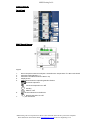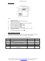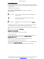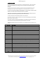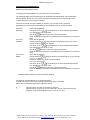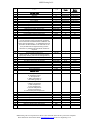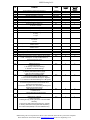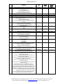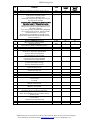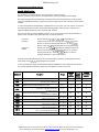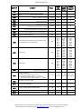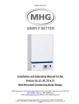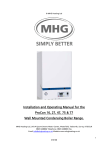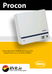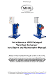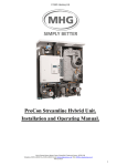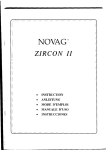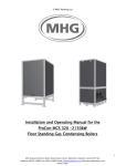
1
MHG Heating Ltd ©
ProCon HT Commissioning Data.
To ensure that the ProCon HT Cascade Manager operates satisfactorily the following sensors
or substitute resistors must installed.
A QAD/Z 21 Flow Sensor (Located on the system side of the low loss header. Remote sensor (QAD 21) required on cascade manger.)
A QAD/Z 21 Return Sensor (Located on the boiler side of the low loss header.)
A QAC32 Outside air sensor or Substitute Resistor simulating –10C (620.Ohms) (Part #RES620)
LPB Wiring Configuration and Type
The interconnecting cascade wiring from the ProCon HT Cascade Master to the ProCon HT
Cascade Slaves must be connected as follows:
In a parallel configuration using screened cable. (The screening must be earthed)
LPB Connections.
MB
DB
Communication Operation Indications
The RED LED on the OCI420 communication clip mounted on the front of each LMU64 module
controller flashes to indicate the detected operational status of the module dictated by the LPB
communication from the ProCon HT Masters RVA47 Cascade Manager.
LED FLASH STATUS
INTERPRETATION OPTIONS
LED ON Constantly
OCI420 not configured to operate with LMU64
LED OFF Constantly
OCI420 Configured. LPB Short Circuit / No Power.
LED ON 93% OFF 7%
OCI420 and LUM64 Not Compatible / LPB Address inadmissible.
LED ON 5% OFF 95%
Boiler being controlled via LPB and required to be not
operating.
LED ON 5% OFF 20% ON 5% OFF70%
Boiler being controlled via LPB and required to be operating.
MHG Heating Ltd Unit 4 Epsom Downs Metro Centre Waterfield Tadworth Surrey KT20 5LR Telephone
08456 448802 Fax 08456 448803 Email [email protected] Web www.mhgheating.co.uk
MHG Heating Ltd ©
Appliance Controls
Control Panel
RVA47 Cascade Manager
Legend
1.
2.
3.
4.
5.
Room Temperature Set Point Adjuster. Assumed Room Temperature if no Room Unit Fitted
Parameter Setting Buttons - / +
Parameter Line Selection Buttons Down / Up
Display Screen
Mode Selection Buttons. Operating Mode Indication
Automatic Operation
Continuous Operation On / Off
Standby
6.
HWS On / Off
Manual Override Button and Indicator
7.
Manual Operation On / Off
Computer Access Port
MHG Heating Ltd Unit 4 Epsom Downs Metro Centre Waterfield Tadworth Surrey KT20 5LR Telephone
08456 448802 Fax 08456 448803 Email [email protected] Web www.mhgheating.co.uk
MHG Heating Ltd ©
Module Controller
Legend
1.
2.
3.
4.
5.
Module Power Isolator
Infrared Output to Flue Gas Analyzer Optional Extra.
Module Numerical Indicator
Temporary Connection Port For QAA73 for LMU 64 Configuration.
Indication of System Pressure
(Not Used)
6.
Indication of Module Over Temperature
7.
8.
9.
10.
Indication of Module Lockout
Indication of Module Burner Activation
Module Lockout Reset Button (To be pressed for at least 3 Seconds)
Display Alteration Button
11.
Commissioning Mode Activation Button
Module Controller End User Settings.
The Module Controller provides access to the End User adjustable parameters P parameters
along with other operational information only settings A, B, C & D parameters.
End User Adjustable Parameters. (Default = Recommended Settings)
Parameter
P0
P1
P2
Function
Range
Default
Required Module Flow Temperature / Room
Temperature. (Outside air sensor attachment dependant. Without = Flow Temperature)
Required HWS Set Point.
20-900C / 10-300C
85 / 200C
10-800C
600C
NA
NA
-- / 40
-31 / +31
NA
NA
32
0
(Only Used if the Module is Directly Controlling HWS Generation)
P3
P4
P5
P6
Not used in This Configuration
Not used in This Configuration
Weather Compensation Curve Heating Circuit 1
Weather Compensation Curve Parallel
Displacement
MHG Heating Ltd Unit 4 Epsom Downs Metro Centre Waterfield Tadworth Surrey KT20 5LR Telephone
08456 448802 Fax 08456 448803 Email [email protected] Web www.mhgheating.co.uk
MHG Heating Ltd ©
Accessing Module Parameters
1. Press the display mode button (10) to choose display level «P» (keep button depressed).
2. Press the display mode button (10) to choose the required parameter (press button briefly).
3. Adjust the value:
Changing parameters: (only P0...P6)
Only parameters P0...P6 can be changed.
To do this, wait until the value of the parameter flashes on the display (3).
Proceed as follows:
P ❍ (+) or (Enter)
❍ (-)
P ❍ (+) or (Enter)
Increase value (+): Press display mode button (10) briefly several
times (< 1 second)
Decrease value (-): Press chimney sweep button (11) briefly
several times (< 3 seconds)
Save value (Enter): Press display mode button (10) for at least 3
seconds
If the displayed value does not require amending or the altered setting is not required do
not press any buttons on the controller for a period greater than 12 seconds.
As a confirmation, the display (3) shows P0...P6 in consecutive order and the newly adjusted
value.
The new value will only be adopted after storage.
Reviewing the Parameter Values
To query the different parameter values, proceed as follows:
Choosing the display mode
Choose the display mode by pressing button (10) for more than 3 seconds (display (3): A...).
Keep button (10) depressed to reach the different display levels b, C, d, P
and back to A.
Release the button when the required display level is reached (A, b, C, d, P).
Choosing and displaying individual values or parameters
To change between the different values or parameters (0… max. 7) of the different display
levels (A, b, C, d, P), press button (10) briefly.
The current value appears about 2 seconds after choosing the relevant parameter.
MHG Heating Ltd Unit 4 Epsom Downs Metro Centre Waterfield Tadworth Surrey KT20 5LR Telephone
08456 448802 Fax 08456 448803 Email [email protected] Web www.mhgheating.co.uk
MHG Heating Ltd ©
Module Operating Codes
MHG Heating Ltd Unit 4 Epsom Downs Metro Centre Waterfield Tadworth Surrey KT20 5LR Telephone
08456 448802 Fax 08456 448803 Email [email protected] Web www.mhgheating.co.uk
MHG Heating Ltd ©
Appliance Error Codes
If a fault is encountered within the appliance or Cascade LPB network, a fault code will be
generated and displayed by the failing module and all LPB networked RVA47 Cascade
Managers.
If a fault is encountered by a module the respective code will be displayed along with a
flashing LED. Three digit codes will be displayed in two consecutive sections. I.e. 1-53 = 153.
If a fault is encountered by a RVA47 Cascade Manager or communicated to a RVA47 Cascade
Manager via the LPB network ER will be generated on the display.
Opening the controllers flap and pressing the Down PROG button twice will gain access to
parameter line 50 where the generated fault code can be reviewed.
In either case the fault code should be noted for future reference.
If the fault is related to a specific module the unit can be rest by pressing the Lockout Reset
Button (9) for at least 3 seconds.
If the fault is related to a RVA47 Cascade Manager or the LPB communication network the
fault code will clear automatically following the rectification of the fault.
This is also applicable following the rectification of any module fault. This can take up to 10
minutes.
Fault Code
E-0
E-10
E-20
E-26
E-28
E-40
E-46
E-50
E-52
E-58
E-60
E-61
E-62
E-77
E-78
E-81
E-82
E-86
E-91
E-92
E-100
E-105
E-110
E-111
E-113
E-117
E-118
E-119
E-124
E-128
E-129
Description
No Error Detected
Outside Air Sensor Fault / Not Detected
Flow Water Sensor Fault / Not Detected
System Flow Sensor Faulty / Not Detected
Flue Gas Sensor Fault / Not Detected
Return Water Sensor Fault / Not Detected
System Return Water Sensor Fault / Not Detected
HWS Sensor Short Circuit 1
HWS Sensor Short Circuit 2 (Not Used)
HWS Volt Free Switch Fault / Not Detected
Faulty Room Sensor
Faulty Room Sensor
Incorrect Room Unit Connected
Air Pressure Sensor Not Detected (Not Used)
Water Pressure Sensor Defective (Not Used)
LPB Short Circuit (Boiler Cascade Wiring)
LPB Address Conflict (Boiler Cascade Settings)
Short Circuit on PPS Connection (Not Used in ProCon Configuration)
EEPROM
Hardware Malfunction
Conflict Between Time of Day Master Control (Boiler / QAA70 / RVA47)
Module Requires Annual Service (QAA73 Room Unit Required to Rest Timer)
Module Water Temperature Overheat
Module Temperature Too High (Auto Resetting)
Flue Gas Temperature overheat (Not Used)
High System Water Pressure Sensor (Not Used)
Low System Water Pressure Sensor (Not Used)
System Water Pressure Switch Activated (Below 0.8 bar)
Module Temperature Too High (Auto Resetting)
Flame Extinguished During Operation (LMU Version D)
Air Supply Error. Fan speed incorrect during operation. (LMU Version D)
MHG Heating Ltd Unit 4 Epsom Downs Metro Centre Waterfield Tadworth Surrey KT20 5LR Telephone
08456 448802 Fax 08456 448803 Email [email protected] Web www.mhgheating.co.uk
MHG Heating Ltd ©
E-130
E-131
E-132
E-133
E-134
E-135
E-140
E-142
E-145
E-146
E-147
E-148
E-150
E-151
E-152
E-153
E-154
E-160
E-161
E-162
E-164
E-166
E-180
E-181
E-183
Flue Temperature Too High (Auto Resetting)
Fault With Burner
External Safety Interlock Activated (Open Circuit)
No Flame Detected After Final Ignition Attempt
Flame Extinguished During Operation LMU Version C)
Air Supply Error. Fan speed incorrect during operation. (LMU Version C)
LPB Segment / Address Not Recognized (Boiler Cascade Settings)
LPB Missing Partner (Boiler Cascade Settings)
Wrong Device Connected to PPS Circuit (Not Used in ProCon Configuration)
Unrecognized Plant Configuration
Burner Modules Not Connected (PPS Circuit Not Used in ProCon Configuration )
LPB Interface Not Configured (Boiler Cascade Settings)
General Boiler Fault
Module LMU64 Controller Malfunction
Module LMU64 Controller Parameter Programming Error
Module Control Interlocked
Module Operating Outside of Predefined Parameters. (System Hydraulic Error.)
Fan Not Reaching Set Point
Module Combustion Fan Speed Too High
Air Pressure Switch Fault (Not Used)
Flow Switch / Pressure Switch Open (Not Used)
Air Pressure Switch Fault (Not Used)
Module Operating in Chimney Mode 100% Output
Module Operating in Commissioning Mode
Module Controller / QAA73 Room Unit in Parameter Setting Mode
MHG Heating Ltd Unit 4 Epsom Downs Metro Centre Waterfield Tadworth Surrey KT20 5LR Telephone
08456 448802 Fax 08456 448803 Email [email protected] Web www.mhgheating.co.uk
MHG Heating Ltd ©
Control Parameter Default Settings.
RVA47 Cascade Manager Settings.
The Single and Cascade Master units are preset for correct operation.
The following Pages detail the parameters of the RVA47 Cascade Manager and the Standard
Factory settings, please note, the installer/commissioning engineer may have changed some
of these settings to suit the system installed.
There are two levels of access available, as follows. If you cannot access a particular
parameter line, please consult with MHG’s Technical Department for further assistance.
Level One
(End User)
-
Level Two
(Installer)
-
Level Three
(OEM)
-
Open The Hinged Flap.
Program Buttons to access the desired parameter
Use either of the
line. (Parameter Line range 0-50)
Use the
Buttons to alter the required parameter.
Once all alterations have been completed press the AUTO button to exist this
level.
Open The Hinged Flap.
Program Buttons simultaneously for more than 3
Press & Hold the
seconds until Parameter # 51 appears.
Program Buttons to access the desired parameter
Use either of the
line. (Parameter Line range 51-173)
Use the
Buttons to alter the required parameter.
Once all alterations have been completed press the AUTO button to exist this
level.
Open The Hinged Flap.
Press & Hold the
Program Buttons simultaneously for up to 9 seconds
until - - - - - appears.
A password will be required to access this level.
(Down Down Plus Minus Plus)
Use either of the
Program Buttons to access the desired parameter
line. (Parameter Line range 2-92)
Buttons to alter the required parameter.
Use the
Once all alterations have been completed press the AUTO button to exist this
level.
Complete RVA47 Cascade Controller Parameter Settings.
The defaults indicated below are for standard systems.
If additional control features are required alteration will have to be made.
Please refer to the RVA47 manual for additional details.
#, -, ----
Indicates where an input can be made if required.
Indicates where an input can not be made and a sensed / attenuated figure is
displayed. ‘OFF’ will be displayed if the +/- buttons are used.
MHG Heating Ltd Unit 4 Epsom Downs Metro Centre Waterfield Tadworth Surrey KT20 5LR Telephone
08456 448802 Fax 08456 448803 Email [email protected] Web www.mhgheating.co.uk
MHG Heating Ltd ©
[#]
1
2
3
4
5
6
7
8
9
10
11
13
14
15
16
17
18
19
23
30
31
32
33
34
35
50
51
52
53
56
57
59
60
61
62
66
69
Description
End User Level
Time of Day
Weekday
Date
Year
Day of Week
Heating Time Switch 1st On Time
Heating Time Switch 1st Off Time
Heating Time Switch 2nd On Time
Heating Time Switch 2nd Off Time
Heating Time Switch 3rd On Time
Heating Time Switch 3rd Off Time
Required HWS Temperature
Heating Night Setback Temperature
Frost Protect Temperature
Summer/Winter Changeover Temperature
Weather Compensation Curve.
If a 0-10 volt signal is the required heat generation
control method for the RVA47 / boiler installation this
setting must be adjusted to -- on all RVA47s present in
the boiler cascade installation. This will result in the
Auto, On/Off and Frost lights becoming inactive.
Alteration to parameter #170 and #172 will also be
required.
Actual Room Temperature
Actual Outside Temperature
(Pressing the + & - buttons simultaneously until the
display stops flashing will reset the averaged value.)
Restore User Level Factory Presets
Hot Water Time Switch 1st On Time
Hot Water Time Switch 1st Off Time
Hot Water Time Switch 2nd On Time
Hot Water Time Switch 2nd Off Time
Hot Water Time Switch 3rd On Time
Hot Water Time Switch 3rd Off Time
Fault Code Display
Engineer Level
Output Test
0. Automatic control
1. All outputs off
2. HWS pump/valve on
3. Circulating pump on
Input Test
0. Return Temperature
1. HWS Temperature
2. Flow Temperature
3. Outside Temperature
4. Room Temperature
5. 0-10 Volt Required Temperature
Plant Type
Actual System Flow Temperature
Actual System Return Temperature
Actual System HWS Temperature
Attenuated Outside Air Temperature
Composite Outside Air Temperature
Outside Air Temperature Source
Maximum System Flow Temperature
Maximum HWS Temperature
Range
150 & 225
Single
150 & 225
Master
Cascade
00:00-24:00
1-7
00:00
1900-3000
00:00-24:00
00:00-24:00
00:00-24:00
00:00-24:00
00:00-24:00
00:00-24:00
40-60
10-30
4-15
8-30
0-40
As Required
As Required
As Required
As Required
As Required
06:00
22:00
55
16
10
30
32
As Required
As Required
As Required
As Required
As Required
06:00
22:00
55
16
10
30
32
0-50
-50-+50
---
---
0-1
00:00-24:00
00:00-24:00
00:00-24:00
00:00-24:00
00:00-24:00
00:00-24:00
0-255
0
06:00
22:00
--
0
06:00
22:00
--
0-3
0
0
0-5
0
0
0-100
0-140
0-140
0-140
-50-+50
-50-+50
00.01/14.16
8-85
8-85
----------
----------
1.7 1.5 6.7 1-7
MHG Heating Ltd Unit 4 Epsom Downs Metro Centre Waterfield Tadworth Surrey KT20 5LR Telephone
08456 448802 Fax 08456 448803 Email [email protected] Web www.mhgheating.co.uk
MHG Heating Ltd ©
[#]
Description
Range
150 & 225
Single
70
71
72
75
76
77
95
100
101
Nominal Room Temperature Set Point
Set Point Of Room Temperature
System Flow Temperature Set Point
Modules Available in Cascade
Lead Module in Cascade
Hour of Operation Until Sequence Change
Heating Pump Output (HKP) Output Functions
Displacement Of Weather Compensation Curve
Gain Factor/Room Influence
0. Active 1. Inactive
Room Temperature Switching Differential
Minimum System Flow Temperature
Maximum System Flow Temperature
Building Construction Type
0. Heavy
1. Light
0.0-35.0
0.0-35.0
0-140
00.1/16.3
00.1/16.3
0.990
1-5
-4.5 - +4.5
0-1
------1
0
1
150 & 225
Master
Cascade
------1
0
1
---/0.5-4
8-95
8-95
0-1
--8
82
1
--8
82
1
Adaptation of Heat Curve
0. Inactive
1. Active
Optimum Start Time Maximum Forward Shift.
00:00 Inactive
Optimum Stop Time Maximum Forward Shift
00:00 Inactive
Heating Zone Quick Setback Constant
Over Heat Protection Heating Zone Pump
Legionella Protection Function 0. Off. 1. On
Legionelle Protection Temperature
HWS Pump Operation Function. (Stored > Flow Temp)
0. Off 1. Always On 2. Only On When Boiler is
Interlocked Off Via 170=3
Reduced HWS Temperature Set Point
0-1
0
0
00:00-06:00
00:00
00:00
00:00-06:00
00:00
00:00
0-20
0-1
0-1
8-95
0-2
2
0
0
65
0
2
0
0
65
0
8-70
40
40
0-2
2
2
0-1
1
1
0-2
2
2
0-1
1
1
0-1
0
0
0-30
20
20
0-3
1
1
102
103
104
105
106
107
108
109
110
117
118
119
120
121
122
123
124
125
126
127
HWS Time Control
0. 24 Hours per Day
1. As Heating Time Switch Settings
2. As HWS Time Switch Settings
HWS Pump Control
0. Heating Time Switch Setting Apply
1. HWS Time Switch Settings Apply
HWS Control in Cascade System
0. Controlled Via Master RVA47 Manager
1. Controlled Via All RVA47 Managers in Segment
2. Controlled Via All RVA47 Managers In LPB System
HWS Charging Cycles Per 24 Hour Period
0. One Per Day with 2.5 Hour Forward Shift from
Heating Time Switch Setting
1. Several Per Day with 1 Hour Forwarding Shifting from
Heating Time Switch Setting
HWS Temperature Control
0. QAZ21 Sensor
1. Volt Free Enable via Thermostat
System Flow Temperature Boost When HWS Enabled
HWS Priority / Shifting
0. Absolute Priority
1. Shifting Priority. Heating Reduced to Increase HWS
Recovery
2. No Priority. HWS and Heating Operate in parallel
3. Shifting / Absolute Heating Switched OFF, Mixing
Circuit Decreased (RVA46) to Increase HWS Recovery.
MHG Heating Ltd Unit 4 Epsom Downs Metro Centre Waterfield Tadworth Surrey KT20 5LR Telephone
08456 448802 Fax 08456 448803 Email [email protected] Web www.mhgheating.co.uk
MHG Heating Ltd ©
[#]
Description
Range
150 & 225
Single
130
131
Hours Of Operation Prior to Sequence Rotation
Changeover Sequence Program
0. No Exemptions
1. The First Module is Exempt
2. The Last Module is Exempt
3. The First and Last Modules are Exempt
Module Designated as Fixed Lead Unit
Cascade Enable Delay Time
Anti Cycling Time (Seconds)
LPB Control Address
0. Single RVA47 Manager. (Not used in FS Configuration.)
1. Master RVA47 Manager
2….16. Slave RVA47s Operating From Master RVA47
Manager
LPB Control Segment
0. Heat Generating Units (RVA47s)
1…14. Heat Consuming Units (RVA46s)
LPB Power Supply
0. Off
1. On
Operation of LPB Power Supply
10-990
0-3
10
0
150 & 225
Master
Cascade
10
0
00.1-16.3
1-120
0-1800
0-16
--1
30
1
--1
30
1
0-14
0
0
0-1
1
1
On/Off
On
On
On/Off
0-1
On
1
On
1
0-1
0
0
0-1
0
0
0-3
2
2
Date/Month
25.03
25.03
Date/Month
25.10
25.10
0-4
0
0
132
133
134
140
141
142
143
144
145
146
147
148
149
150
170
Display of LPB Communication
Changeover Via LPB Connection
0. All Controllers in Same Segment
1. All Controllers in LPB System
Summer/Winter Changeover Via LPB
0. Local Control Only
1. Entire Control Via LPB
Central Standby Switching
0. Deactivated
1. Activated
Clock Mode
0. Autonomous All Clocks Can Have Different Times
1. System Time Without Adjustment
2. System Time With Adjustment
3. System Clock Master. There Can Only be One Master
Auto Time Adjustment Spring
Date and Month of Last Sunday in March
Auto Time Adjustment Autumn
Date and Month of Last Sunday in October
Operation of H1 Terminal
0. Changeover of Operation When Volt Free Switch is
Made. (HWS Stopped)
1. Changeover of Operation When Volt Free Switch is
Made. (HWS Unaffected)
2. Minimum Flow Temperature Maintained When Volt
Free Switch is Made. (Set at 171.)
3. Heat Generation Stopped When Volt Free Switch is
Made.(Frost Active)
4. 0-10 Volt Control to Vary System Flow Temperature.
(Curve set at 172)
(Terminal #1. 0-10 volt. Terminal #2. Ground.)
{If a 0-10 volt signal is the required heat generation
control method for the RVA47 / boiler installation this
setting must be adjusted to 4. Alterations must also be
made to parameter #17. The setting must be adjusted
from 32 to – on all RVA47s present in the boiler cascade
installation. This will result in the Auto, On/Off
and Frost lights becoming inactive. Possible alterations
to parameter #172 may also be required.}
MHG Heating Ltd Unit 4 Epsom Downs Metro Centre Waterfield Tadworth Surrey KT20 5LR Telephone
08456 448802 Fax 08456 448803 Email [email protected] Web www.mhgheating.co.uk
MHG Heating Ltd ©
[#]
Description
Range
150 & 225
Single
171
172
173
Minimum Temperature Set Point Via H1 (170 = 2)
Maximum Temperature Set Point Via H1 (170 = 4)
Operating Action of H1 control contacts.
0. The contact is Normally Closed.
1. The contact is Normally Open.
{The RVA47 will operate according to its internal
time switches and presets.
If a remote BMS is controlling the RVA47 via a Volt
Free switch across H1 ‘0’ should be inserted.
This will allow the boilers operate when the Volt
Free switch is made and stopped (Blocked.) when
the switch is opened.
If you are controlling the lead (master) RVA/Boiler
via a volt free switch across H1, all slave modules
should be left with ‘1’ as the input.
This will allow the AUTO light and the OFF light to
indicate their operational mode dictated by the lead
(master) RVA/Boiler.}
OEM Level
Maximum Module Temperature
When Operating In Manual Mode
Pump Run On Time
System Heating (HKP) and HWS (SLP) Pumps
Minimum System Return Temperature
Room Influence Gain Factor
Boost Room Temperature Set Point
Room Sensor Dependant (QAA10/50/70)
Increase. Heat Up Time Reduced
Decrease Heat Up Time Increased
Frost Protection
0. Frost Protection Program Disabled
1. Frost Protection Program Enabled
Heat Gains
Increase. If Heat Gains are High
Decrease. If Heat Gains are Low
Adaptation Sensitivity 1
Outside Air Range 4-12 C
Adaptation Sensitivity 2
Outside Air Range <4 C
Maximum HWS Set Point
HWS Switching Differential (QAZ21 Sensor Only)
Legionella Function 0. Off 1. On
Cascade Strategy
1-3 Automatic
4-6. Fixed
Minimum % Output reached Prior to Switching Off a
Module In the Cascade
Maximum % Output Reached Prior to Switching On o
Module In The Cascade
Time Spent By Module On Ignition Rate Prior to
Modulation (Delay Time Between Modules)
Minimum Temperature Difference Between Flow/
Return Sensor Readings Prior to The Return Sensor
Becoming Lead
Display Default
0. Time of Day
1. System Flow Temperature (CA)
Software Version
RVA47 Manager Operating Hours
8-95
5-130
0-1
80
82
1
150 & 225
Master
Cascade
80
82
1
8-120
82
82
0-20
3
3
8-95
0-20
0-20
8
4
5
8
4
5
0-1
1
1
-2-+4
0
0
1-15
15
15
1-15
15
15
8-80
0-20
0-1
1-6
60
5
0
3
60
5
0
3
5-100
20
20
5-100
85
85
0-1200
0
0
0-20
2
2
0
0
#
--
#
--
2
8
22
30
32
33
35
36
0
37
0
40
41
42
50
51
52
56
60
90
91
92
00.0-99.9
0-500,000
MHG Heating Ltd Unit 4 Epsom Downs Metro Centre Waterfield Tadworth Surrey KT20 5LR Telephone
08456 448802 Fax 08456 448803 Email [email protected] Web www.mhgheating.co.uk
MHG Heating Ltd ©
Control Parameter Default Settings.
Module LMU64 Setting.
The Standalone and Cascade Master units are preset for correct operation.
However the slave units may require modest parameter updating. (Usually limited to H605)
The following Pages detail the parameters of the modules and the Standard Factory settings, please
note, the installer/commissioning engineer may have changed some of these settings to suit the system
installed.
To access the parameters detailed below a QAA73 Room Unit is require. The unit must be connected to
the respective Module Controller Via the dedicated Plug, Behind cover plate (4) or directly to the
respective LMU64 module controller. Via the X10:01 Terminal.
There are two levels of access available, as follows. If you cannot access a particular parameter line,
please consult with MHG’s Technical Department for further assistance.
Level One
(Installer)
-
Press & Hold the
or
Program Buttons
simultaneously for at least 3 seconds. Use the
Program
Buttons to access the desired parameter line. Use the
Button to alter the displayed parameter to the required setting.
Level Two
(OEM)
-
Press & Hold the
Program Buttons simultaneously for at
least 3 seconds Use the
Program Buttons to access the
desired parameter line. Use the
Button to alter the
displayed parameter to the required setting.
An altered parameter will be saved to the controllers memory by leaving the displayed parameter
when either of the
Program Buttons are pressed.
To exit the parameter review and amendment levels the INFO Button of the QAA73 must be pressed.
Any unsaved parameter alterations will be lost if the QAA73 is version 1.3 or lower.
QAA73 #
Description
H90
Reduced Temperature for DHW
H91
DHW Production Control
H93
DHW Production Control 0=Non Eco 1=Eco
H94
H503
(0=Time control 1=Constant)
DHW Secondary Pump Control
(0= As H91. 1= As HWS Time Switch)
(K2, X2:03, H615:6)
Minimum boiler setpoint temperature
(20 °C<=TkSmin<=TkSmax)
H504
Maximum boiler setpoint temperature
H505
Boiler setpoint at design outside temperature
Minimum flow setpoint temperature
H506
(TkSmin<=TkSmax<=90 °C)
(20 °C<=TvSmin<=TvSmax)
H507
Maximum flow setpoint temperature
H516
Summer / winter changeover temperature
H532
Heating curve slope heating circuit 1
(TvSmin<=TvSmax<=90 °C)
(30 °C: S / W changeover deactivated)
Range
150 & 225
Single
Defaults
150 & 225
Cascade
Master
Defaults
150 & 225
Cascade Slave
Defaults
8….60
10
10
10
0…1
0
0
0
0…1
0
0
0
0…1
0
0
0
20 ... 90 °C
20
20
20
20 ... 90 °C
90
90
90
20 ... 90 °C
85
85
85
20 ... 90 °C
25
25
25
20 ... 90 °C
90
90
90
8 ... 30 °C
18
18
18
1 ... 40
32
32
32
MHG Heating Ltd Unit 4 Epsom Downs Metro Centre Waterfield Tadworth Surrey KT20 5LR Telephone
08456 448802 Fax 08456 448803 Email [email protected] Web www.mhgheating.co.uk
MHG Heating Ltd ©
QAA73 #
Description
H533
Heating curve slope heating circuit 2
H536
Maximum speed at maximum output in heating
mode
(maximum speed limitation)
Range
150 & 225
Single
Defaults
150 & 225
Cascade
Master
Defaults
150 & 225
Cascade Slave
Defaults
1 ... 40
32
32
32
0 ... 9950 rpm
7000
7000
7000
0 ... 100 %
100
100
100
0 ... 9999 kW
15
15
15
0 ... 9999 kW
75
75
75
0 ... 255 min
10
10
10
0 ... 3600 s
300
300
300
H541
Maximum degree of modulation in heating mode
H542
Minimum boiler output in kW
H543
Maximum boiler output in kW
H544
Overrun time of pumps, max. 210 min
H545
Minimum burner pause time
H551
Constant for quick setback without room influence
0 ... 20
2
2
2
H552
Hydraulic system adjustment
0 ... 255
80
80
80
b0=1
b1=0
b2=1
b3=1
b4=0
b5=1
b6=0
b7=0
b0=0
b1=0
b2=0
b3=0
b4=1
b5=0
b6=0
b7=0
b0=1
b1=0
b2=0
b3=0
b4=0
b5=0
b6=1
b7=0
b0=1
b1=0
b2=1
b3=1
b4=0
b5=1
b6=0
b7=0
b0=0
b1=0
b2=0
b3=0
b4=1
b5=0
b6=0
b7=0
b0=1
b1=0
b2=0
b3=0
b4=0
b5=0
b6=1
b7=0
b0=1
b1=0
b2=1
b3=1
b4=0
b5=1
b6=0
b7=0
b0=0
b1=0
b2=0
b3=0
b4=1
b5=0
b6=0
b7=0
b0=1
b1=0
b2=0
b3=0
b4=0
b5=0
b6=1
b7=0
150
150
150
(LmodTL <= PhzMax <= LmodVL)
(lower calorific value)
(lower calorific value)
(setting 255: continuous operation of Q1)
(heat demand-dependent switching hysteresis)
H554
Setting flags: status code open-circuit sensor for ANx
channel suppressed / not suppressed
0 ... 255
H555
Setting flags
0 ... 255
H558
Setting flags
0 ... 255
H596
Running time of actuator in heating circuit 2
(TimeOpening / TimeClosing)
30 ... 873 s
LPB device number of LMU
H605
* Module numbering
150 Stand Alone & Master Upper 2 Lower 3
Cascade Slave Upper 4, Lower 5………16 ETC
225 Stand Alone & Master Upper 2, Middle 3, Lower 4
Cascade Slave Upper 5, Middle 5, Lower 6………16 ETC
0 ... 16*
2,3, (150)* 2,3, (150)* 4,5-16 (150)*
2,3,4 (225)* 2,3,4 (225)* 5,6,7-16(225)*
H606
LPB segment number of LMU
0 ... 14
0
0
0
H614
Program input LMU basis
0 ... 255
3
3
3
H615
Function programmable output K2 LMU
0 ... 255
0
0
0
H618
Progr input on clip-in function module
0 ... 255
0
0
0
H619
Function output1 clip-in function module
0 ... 255
0
0
0
MHG Heating Ltd Unit 4 Epsom Downs Metro Centre Waterfield Tadworth Surrey KT20 5LR Telephone
08456 448802 Fax 08456 448803 Email [email protected] Web www.mhgheating.co.uk
MHG Heating Ltd ©
QAA73 #
Description
Range
150 & 225
Single
Defaults
150 & 225
Cascade
Master
Defaults
150 & 225
Cascade Slave
Defaults
H620
Function output2 clip-in function module
0 ... 255
0
0
0
H621
Function output3 clip-in function module
0 ... 255
0
0
0
H622
Maximum value of heat demand with external
predefined temperature setpoint
5 ... 130 °C
85
85
85
b0=1
b1=0
b2=0
b3=0
b4=0
b5=0
b6=0
b7=0
b0=1
b1=0
b2=0
b3=0
b4=0
b5=0
b6=0
b7=0
(5 °C< = TAnfoExtMax< = 130 °C)
H630
Setting flags of maintenance alarms
0 ... 255
b0=1
b1=0
b2=0
b3=0
b4=0
b5=0
b6=0
b7=0
H636
Months (interval) since last service visit
0 ... 255
months
0
0
0
H700
1st Historical Fault – Number of Occurrences.
H701
1st Historical Fault – Operating Phase.
H702
1st Historical Fault – Operating Error Code
H703
2nd Historical Fault – Number of Occurrences.
H704
2nd Historical Fault – Operating Phase.
H705
2nd Historical Fault – Operating Error Code
H706
3rd Historical Fault – Number of Occurrences.
H707
3rd Historical Fault – Operating Phase.
H708
3rd Historical Fault – Operating Error Code
H709
4th Historical Fault – Number of Occurrences.
H710
4th Historical Fault – Operating Phase.
H711
4th Historical Fault – Operating Error Code
H712
5th Historical Fault – Number of Occurrences.
H713
5th Historical Fault – Operating Phase.
H714
5th Historical Fault – Operating Error Code
H715
Current Historical Fault – Number of Occurrences
H716
Current Historical Fault – Operating Phase.
H717
Current Historical Fault – Operating Error Code
H718
Hours run burner
0
0
0
H719
Hours run heating mode
0
0
0
H720
Hours run DHW heating
0
0
0
H721
Hours run zone
0
0
0
0 ... 131070
hrs
0 ... 131070
hrs
0 ... 131070
hrs
0 ... 131070
hrs
MHG Heating Ltd Unit 4 Epsom Downs Metro Centre Waterfield Tadworth Surrey KT20 5LR Telephone
08456 448802 Fax 08456 448803 Email [email protected] Web www.mhgheating.co.uk
MHG Heating Ltd ©
QAA73 #
Description
H722
Start counter
H727
Current Fault Code – ALBATROS Error Code
H728
1st Historical Fault – ALBATROS Error Code
H729
2nd Historical Fault – ALBATROS Error Code
H730
3rd Historical Fault – ALBATROS Error Code
H731
4th Historical Fault – ALBATROS Error Code
H732
5th Historical Fault – ALBATROS Error Code
H732
Current Historical Fault – ALBATROS Error Code
H755
Measured value of ionization current
Range
150 & 225
Single
Defaults
150 & 225
Cascade
Master
Defaults
150 & 225
Cascade Slave
Defaults
0 ... 327675
0
0
0
0 ... 583
-
Weather Compensation Curve
Module Controller
Legend
1. Module Power Isolator
2. Infrared Output to Flue Gas Analyser Optional Extra.
3. Module Numerical Indicator
4. Temporary Connection Port For QAA73 Unit
5. Indication of System Pressure
(Not Used)
6. Indication of Module Over Temperature
7. Indication of Module Lockout
8. Indication of Module Burner Activation
9. Module Lockout Reset Button (To be pressed for at
least 3 Seconds)
10. Display Alteration Button
11. Commissioning Mode Activation Button
MHG Heating Ltd Unit 4 Epsom Downs Metro Centre Waterfield Tadworth Surrey KT20 5LR Telephone
08456 448802 Fax 08456 448803 Email [email protected] Web www.mhgheating.co.uk
MHG Heating Ltd ©
Commissioning The Appliance
Pre-Commissioning Checks
Prior to undertaking the commissioning of the unit please ensure that the system water has
been cleansed and treated with a suitable inhibitor as detailed in Filling the system and
system water quality.
Prior to applying power to the individual modules their dedicated circulation pumps should
be bleed and checked to ensure free rotation of the armature.
Combustion System Commissioning.
The commissioning function enables the boiler to be started up in heating mode by
pressing the
Chimney Sweep Button (11) on the module controller.
There are two levels of operation accessed via the
Chimney Sweep Button (11)
Operation at Maximum Output With No Adjustment.
Pressing the
Chimney Sweep Button (11) for more than 3 seconds but less than 6 seconds
places the respective module in High Fire mode.
To indicate that the module is operating under the control of the Chimney Sweep Button
the display (3) will indicate SF and the red Lockout LED (7) will flash with a single pulse.
This mode is maintained until the limit thermostat temperature is reached or the
Chimney Sweep Button is pressed from more than 1 second.
Operation at Maximum or Minimum Output For Flue Gas Analysis and Gas Valve Adjustment
Pressing the
Chimney Sweep Button (11) for more than 6 seconds. places the respective
module in High Fire mode.
To indicate that the module is operating under the control of the
Chimney Sweep Button
the display (3) will indicate 100 for High Fire and 0 for Low Fire and the red Lockout LED (7)
will flash with a double pulse.
To alternate the module between High Fire and Low Fire the
P Buttons must be pressed for less than 1 second.
High Fire
Button
P Button
Chimney Sweep and
Low Fire
This mode is maintained until the limit thermostat temperature is reached or the
Chimney Sweep Button is pressed from more than 1 second.
Whilst the module is operating under the control of the Chimney Sweep Button (with
adjustment) the gas valve can be adjusted to give correct flue gas analysis readings.
Each module is equipped with a modulating gas valve.
MHG Heating Ltd Unit 4 Epsom Downs Metro Centre Waterfield Tadworth Surrey KT20 5LR Telephone
08456 448802 Fax 08456 448803 Email [email protected] Web www.mhgheating.co.uk
MHG Heating Ltd ©
The modulating gas valve must be set at High Fire and Low Fire to ensure correct operation
throughout its modulating range.
It is advisable to check the combustion figures on High and Low Fire prior to carrying out
any adjustments.
Adjusting the High Fire has a marked effect on the Low Fire figures.
Where as adjusting the Low Fire has little effect on the High Fire figures.
The High fire adjustment is carried out via the 2.5mm Allen Key socket D
The High Fire adjustment is a Gate type restrictor.
Therefore turning the screw clockwise will close the gate and thus restrict the quantity of
gas passing through to the burner.
The Low fire adjustment is carried out via the 2.5mm Allen Key socket N
The Low Fire adjustment is a diaphragm governor.
Therefore turning the screw clockwise will increase the pressure on the diaphragm and thus
increase the quantity of gas passing through to the burner.
Legend
A.
Valve Inlet Gas Pressure Test Point
B.
Valve Outlet Gas Pressure Test Point
D.
High Fire Adjuster (Gate Type)
N.
Low Fire Adjuster (Governor Type)
Each module must be analysed and adjusted separately.
This is undertaken by inserting the analysers probe in to the
silicone sampling tube secured to the top of each module and sealed with a black plug. If
fluctuating figures are obtained the flue gas analyzer probe should be inserted into the
respective modules flue spigot following the temporary removal of the silicone tube.
(Taking care not to dislodge the grommet.)
Each module must be set to the following combustion figures.
Gas Type
Injector Size
High Fire
Natural Gas (G20)
15mm
8.5% C02
LPG (G31)
10mm
11.0% CO2
Low Fire
9.0% CO2
11.0% CO2
MHG Heating Ltd Unit 4 Epsom Downs Metro Centre Waterfield Tadworth Surrey KT20 5LR Telephone
08456 448802 Fax 08456 448803 Email [email protected] Web www.mhgheating.co.uk