1
Copyright Notice
This documentation and the software included with this product are
copyrighted 2001 by Advantech Co., Ltd. All rights are reserved.
Advantech Co., Ltd. reserves the right to make improvements to the
products described in this manual at any time without notice.
No part of this manual or software may be reproduced, copied,
translated or transmitted, in any form or by any means without the
prior written permission of Advantech Co., Ltd. Information provided
in this manual is intended to be accurate and reliable. However,
Advantech Co., Ltd. assumes no responsibility for its use, nor for any
infringements of rights of third parties which may result from its use.
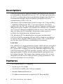
Acknowledgments
PC-LabCard is a trademark of Advantech Co., Ltd. IBM, PC and
PC/XT/AT are trademarks of International Business Machines
Corporation. MS-DOS, MASM, QuickBASIC, Microsoft C and MSPASCAL are trademarks of Microsoft Corporation. Intel is a trademark
of Intel Corporation. Turbo C and Turbo PASCAL are trademarks of
Borland International.
Printed in Taiwan
2nd Edition
July 2001
Contents
Chapter 1: Introduction ................................................ 1
Description ............................................................................. 2
Features .................................................................................. 2
Specifications ......................................................................... 3
Ordering Information .......................................................... 5
Chapter 2: Hardware Configuration ............................. 7
Initial Inspection .................................................................... 8
Jumper and Switch Locations ............................................. 9
Jumper settings ................................................................... 14
How to set jumpers ............................................................ 14
Default Settings ................................................................. 14
Card installation .................................................................. 15
RS-422/485 selection (for PCI-1601/1602/1612) .......... 16
Enable mode selection ...................................................... 16
Terminator resistor setup (for PCI-1601/1602/1612) ..... 16
Chapter 3: Driver Setup & Installation ....................... 17
Overview .............................................................................. 18
For Windows 95/98 Driver Setup ..................................... 18
For Windows NT Driver Setup ......................................... 18
Windows 95/98 Driver Setup............................................. 19
Steps for Windows 95/98 Driver Setup ........................... 19
Reboot your system after Win95/98 driver Setup .......... 22
PCI UARTs Device Driver Installation ...................................................... 22
PCI Bridge Device Driver Installation ........................................................ 26
Verify your Win95/98 Driver Setup ................................. 27
Configure PCI ICOM serial devices on Windows 95/98 31
Configuring PCI UARTs Device ................................................................. 33
Configuring PCI Bridge Device ................................................................... 34
Configuring ports ........................................................................................ 34
Remove PCI ICOM series device..................................... 38
Steps for Complete Win98/98 Driver Uninstall .............. 42
Windows NT Driver Setup ................................................. 43
Steps for Windows NT Driver Setup ................................ 43
Start the Device Function in Windows NT ...................... 47
Verify your NT driver Setup ............................................. 48
Verify your NT Driver Function ...................................... 49
Stop the Device Function in Windows NT ...................... 50
Chapter 4: ICOM Tools ................................................. 51
Introduction ......................................................................... 52
Installation ........................................................................... 52
User Interface of ICOM Tools .......................................... 52
Using the ICOM Tools utility ............................................ 56
Port Selection ..................................................................... 56
4.3.2 Configure the Port .................................................. 58
Run the test ................................................................................................. 59
Stop the test ................................................................................................ 60
Close Port ........................................................................... 61
Exit the ICOM Tools utility ............................................... 61
Messages on the Status Bar and Message Logo area ... 61
Status Bar messages .......................................................... 61
Message Logo messages .................................................. 61
Chapter 5: Pin Assignment & Wiring .......................... 63
Pin assignments ................................................................... 64
PCI-1601/1602 .................................................................. 64
RS-422 signal wiring ........................................................ 64
RS-485 ................................................................................ 64
PCI-1610/1612 .................................................................. 65
PCI-1620 ............................................................................ 66
Wiring ................................................................................... 68
RS-232 signal wiring ........................................................ 68
Terminal or PC (DTE) connections ........................................................... 68
Modem connections ................................................................................... 69
Terminal without handshake ....................................................................... 69
RS-422 signal wiring ........................................................ 70
Terminator Resistors setup ............................................... 70
RS-485 signal wiring ........................................................ 71
Termination resistor setup................................................. 72
CHAPTER
1
Introduction
Chapter 1
Introduction
1
Description
The PCI Local Bus is a high-performance bus that provides a processor-independent data path between the CPU and high-speed peripherals. PCI is a robust interconnect mechanism designed specifically to
accommodate multiple high performance peripherals for series
communication, SCSI, LAN, etc.
Advantech serial communication cards leverages the " Plug and Play
" capability defined in the PCI 2.1 bus specification. The board
requires only one PCI slot within the personal computer and provides
independent serial channels. All channels are addressed in a continuous 32 byte I/O block for simplified software access. And, all channels
may also share one PCI interrupt. An interrupt status register is
available for determining the interrupt source.
The Advantech PCI communication card comes standard with
16PCI954 UARTs containing 128 byte FIFOs which are available as
an option. These upgraded FIFOs greatly reduce CPU overhead and
are an ideal choice for heavy multitasking environments.
16PCI954
The 16PCI954 is a high performance Quad UART with an on-chip PCI
interface. Targeted at PCI-based serial and parallel expansion cards,
PCI-architecture computer systems and embedded applications, the
16PCI954 integrates a PCI bus interface together with four of 16C950
high performance UARTs, a bi-directional parallel port and a local
bus bridge function. This single-chip solution replaces five or more
integrated circuits used in today products, giving performance, cost
and size advantages for new designs.
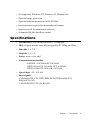
Features
• PCI Specification 2.1 compliant
• Speeds up to 921.6 Kbps
• 16C954/950 UARTs with 128-byte standard
• Standard Industrial Board size
• I/O address automatically assigned by PCI Plug-and-Play
2
PCI Comm Card Series User's Manual
• OS supported: Windows NT, Windows 95, Windows 98
• Optional surge protection
• Optional isolation protection for RS-422/485
• Interrupt status register for increased performance
• Space reserved for termination resistors
• Automatic RS-485 data flow control
Specifications
• Bus Interface: PCI bus specification 2.1 compliant
• IRQ: all ports use the same IRQ assigned by PCI Plug-and-Play
• Data bits: 5, 6, 7, 8
• Stop bits: 1, 1.5, 2
• Parity: none, even, odd
• Communication controller:
16PCI954 + 16C954 for PCI-1620A/B
16PCI954 for PCI-1610A/B, PCI-1612A/B
16PCI954 for PCI-1601A/B, 1602A/B
• Speed (bps) : 50 ~ 921.6 K
• Data signals:
TxD, RxD, RTS, CTS, DTR, DSR, DCD, GND (for RS-232)
RI (for PCI-1610)
TxD, RxD, RTS, CTS (for RS-422)
Chapter 1
Introduction
3
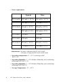
• Power requirement :
Typical
PCI-1620
Max
120 mA (+12 V)
150 mA (+12 V)
180 mA (+5 V)
220 mA (+5 V)
60 mA (+12 V)
80 mA (+12 V)
150 mA (+5 V)
180 mA (+5 V)
PCI-1601
220 mA
270 mA
PCI-1602
250 mA
300 mA
PCI-1612
60 mA (+12 V)
80 mA (+12 V)
270 mA (+5 V)
340 mA (+5 V)
PCI-1610
• Dimensions: 185 mm x 100 mm (for PCI-1612/1620)
123 mm x 92 mm (for PCI-1601/1602/1610)
• Operating temperature: 0o ~ 65o C (referring to IEC
68-2-1, 2)
• Operating Humidity: 5 ~ 95% Relative Humidity, non-condensing
(referring to IEC 68-2-1, 2)
• Operating Humidity: 5 ~ 95% Relative Humidity, non-condensing
(referring to IEC 68-2-3)
• Storage Temperature: -25 ~ 85o C
4
PCI Comm Card Series User's Manual
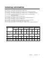
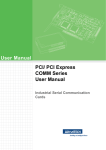
Ordering Information
PCI-1601A: 2-port RS-422/485 PCI Comm Card
PCI-1601B: 2-port RS-422/485 PCI Comm Card, w/surge protection
PCI-1602A: 2-port RS-422/485 PCI Comm Card. w/ isolation protection
PCI-1602B: 2-port RS-422/485 PCI Comm Card, w/isolation and
surge protection
PCI-1620A: 8-port RS-232 PCI Comm Card
PCI-1620B: 8-port RS-232 PCI Comm Card, w/surge protection
PCI-1610A: 4-port RS-232 PCI Comm Card
PCI-1610B: 4-port RS-232 PCI Comm Card, w/surge protection
PCI-1612A: 4-port RS-232/422/485 PCI Comm Card
PCI-1612B: 4-port RS-232/422/485 PCI Comm Card, w/surge protection
PCI-1601
PCI-1602
PCI-1610
PCI-1612
PCI-1620
A
B
A
B
A
B
A
B
A
B
2
2
2
2
4
4
4
4
8
8
Series
No. of Port
Interface
RS-422/485
RS-422/485
RS-232/422/
485
RS-232
RS-232
Surge
Protection
-
2500
VDC
-
2500
VDC
-
3000
VDC
N/A
2500
VDC
-
3000
VDC
Isolation
Protection
-
-
3000
VDC
3000
VDC
-
-
-
-
-
-
Chapter 1
Introduction
5
6
PCI Comm Card Series User's Manual
CHAPTER
Hardware
Configuration
Chapter 2
2
Hardware Configuration
7
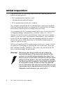
Initial Inspection
You should find the following items inside the shipping package (in
addition to this manual):
• PCI communication interface card
• Advantech Automation Software
• PCI communication card user's manual
We carefully inspected the PCI communication card series mechanically and electrically before we shipped it. It should be free of marks
and scratches and in perfect working order on receipt.
As you unpack the PCI communication card series, check it for signs
of shipping damage (damaged box, scratches, dents, etc.). If it is
damaged or it fails to meet specifications, notify our service department or your local sales representative immediately. Also notify the
carrier. Retain the shipping carton and packing material for inspection by the carrier. After inspection we will make arrangements to
repair or replace the unit.
When you handle the PCI communication card series, remove it from
its protective packaging by grasping the rear metal panel. Keep the
anti-vibration packing. Whenever you remove the card from the PC,
store it in this package for protection.
Warning! Discharge your body’s static electric charge by
touching the back of the grounded chassis of the
system unit (metal) before handling the board. You
should avoid contact with materials that hold a static
charge such as plastic, vinyl and styrofoam. Handle
the board only by its edges to avoid static damage to
its integrated circuits. Avoid touching the exposed
circuit connectors. We also recommend that you use
a grounded wrist strap and place the card on a static
dissipative mat whenever you work with it.
8
PCI Comm Card Series User's Manual
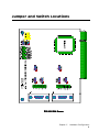
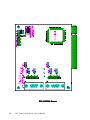
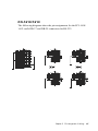
Jumper and Switch Locations
PCI-1601 Silk Screen
Chapter 2
Hardware Configuration
9
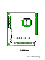
PCI-1602 Silk Screen
10
PCI Comm Card Series User's Manual
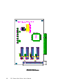
PCI-1610 Silk Screen
Chapter 2
Hardware Configuration
11
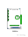
PCI-1612 Silk Screen
12
PCI Comm Card Series User's Manual
PCI-1620 Silk Screen
Chapter 2
Hardware Configuration
13
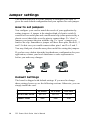
Jumper settings
This section tells how to set the jumpers to configure your card. It
gives the card default configuration and your options for each jumper.
How to set jumpers
You configure your card to match the needs of your application by
setting jumpers. A jumper is the simplest kind of electric switch. It
consists of two metal pins and a small metal clip (often protected by a
plastic cover) that slides over the pins to connect them. To “close” a
jumper you connect the pins with the clip. To “open” a jumper you
remove the clip. Sometimes a jumper will have three pins, labeled 1, 2
and 3. In this case you would connect either pins 1 and 2 or 2 and 3.
You may find pair of needle-nose pliers useful for setting the jumpers.
If you have any doubts about the best hardware configuration for your
application, contact your local distributor or sales representative
before you make any changes.
Open
Closed
Closed 2-3
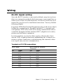
Default Settings
The board is shipped with default settings. If you need to change
these settings, however, see the following sections. Otherwise, you can
simply install the card.
RS-422/485 Mode
Enable Mode
14
PCI-1601
PCI-1602
PCI-1612
RS-422
RS-422
RS-422
Auto
Auto
Auto
PCI Comm Card Series User's Manual
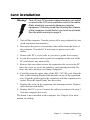
Card installation
Warning! Turn off your PC’s power supply whenever you install
or remove the PCI communication card or its cables.
Static electricity can easily damage computer
equipment. Ground yourself by touching the chassis
of the computer (metal) before you touch any boards.
See the static warning on page 6
1. Turn off the computer. Turn the power off to any peripheral devices
(such as printers and monitors).
2. Disconnect the power cord and any other cables from the back of
the computer. Turn the PC if necessary to gain access to the
cables.
3. Remove the PC’s cover (refer to your user’s guide if necessary).
4. Locate the expansion slots or passive backplane (at the rear of the
PC) and choose any unused slot.
5. Remove the screw that secures the expansion slot cover to the PC
(save the screw to secure the interface card retaining bracket). Re
move the anti-vibration card clamp if supplied.
6. Carefully grasp the upper edge of the PCL-743/745 card. Align the
hole in the retaining bracket with the hole on top of the expansion
slot. Align the gold striped edge connector with the expansion slot
socket. Press the board firmly into the socket.
7. Replace the screw in the expansion slot retaining bracket. Replace
anti-vibration card holder.
8. Replace the PC’s cover. Connect the cables you removed in step 2.
Turn the computer power on.
The board is now installed in the computer. See Chapter 4 for information on cabling.
Chapter 2
Hardware Configuration
15
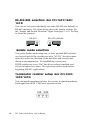
RS-422/485 selection (for PCI-1601/1602/
1612)
You can set each port individually for either RS-422 (the default) or
RS-485 operation. The figure below shows the jumper settings. See
the "Jumper and Switch Locations" figure from page 7 to 11 for help
to locate the jumpers.
RS-485
485
422
RS-422 (default)
485
422
Enable mode selection
You set the Enable mode using two- or four- position DIP switches,
one for each port. If the switches are set to "AUTO", the driver automatically senses the direction of the data flow and switches the
direction of transmission. No handshaking is necessary.
If DIP switches are set to "On," the driver is always enabled, and
always in high or low status. The user must select a mode before
beginning RS-422 applications.
Terminator resistor setup (for PCI-1601/
1602/1612)
You can install terminator resistors if necessary to match impedance.
Each signal line (RTS, CTS) has a separate resistor.
120 300
16
PCI Comm Card Series User's Manual
CHAPTER
Driver Setup &
Installation
Chapter 3
3
Driver Setup & Installation
17
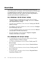
Overview
This chapter describes the driver installation, configuration and
removal procedures for Windows 95/98, and Windows NT. We strongly
recommend that you install the software driver first before you
install the hardware into your system, since this will guarantee a
smooth and trouble-free installation process.
For Windows 95/98 Driver Setup
•
To install the driver for the first time, please refer to Section
“Steps for Windows 95/98 Driver Setup” and Section “Reboot
after Win95/98 driver Setup”
•
To verify your installation, refer to Section “Verify your Win 95/
98 Driver Setup”
•
To configure your PCI ICOM devices, refer to Section “Configure
PCI ICOM Series Devices”
•
To remove the Device from your system, refer to Section “Remove
Advantech PCI ICOM Series Devices”
•
To remove the driver, refer to Section “Steps for Complete
Windows 95/98 Driver Uninstall”
For Windows NT Driver Setup
18
•
To install the driver for the first time, please refer to Section
“Steps for Windows NT Driver Setup”
•
To verify your installation, refer to Section “Verify your NT
Driver Setup”
•
To start the device function, refer to Section “Start the Device
Function”
•
To verify the driver function, refer to Section “Verify your NT
Driver Function”
•
To stop the device function, refer to Section “Stop the Device
Function in Windows NT”
PCI Comm Card Series User's Manual
Windows 95/98 Driver Setup
Windows 95/98 supports up to 256 serial ports, from COM1 to
COM256. Advantech PCI ICOM driver, however, will start to assign
port numbers beginning from COM 5. In order to fully utilize
Windows 95/98 advanced features such as multi-process and multithread , we offer pure 32-bit Windows 95/98 virtual device port
drivers, which are compliant with communication drivers, for the PCI1601/ 1602/ 1610/ 1612/ 1620 multiport boards. All these drivers
conform to Win32 COMM API standard to serve you with a smooth
performance.
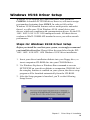
Steps for Windows 95/98 Driver Setup
Before you install the card into your system, we strongly recommend
you install the driver first. Please follow the steps below for the PCI1601/ 1602/ 1610/1612/ 1620 Windows 95/98 driver installation.
1. Insert your driver installation diskette into your floppy drive, or
insert companion CD-ROM disc into your CD-ROM drive.
2. Use Windows Explorer or Windows Run command to execute
SETUP.EXE on your driver diskette or companion CD-ROM. Or if
the autoplay function is enabled on your system, the driver setup
program will be launched automatically from the CD-ROM.
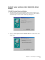
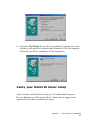
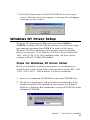
3. After the Setup program is launched, you’ll see the following
Setup Screen.
Chapter 3
Driver Setup & Installation
19
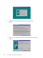
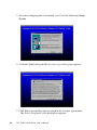
4. Click the Next button and the License Agreement Page
appears.
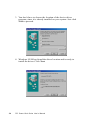
5. Click the Next button and the Choose Destination Location page
appears.
20
PCI Comm Card Series User's Manual
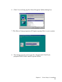
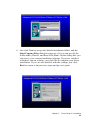
6. Click Next to bring up the Select Program Folder dialog box.
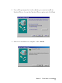
7. The Driver Setup program will begin copying files to your system.
8. The Setup program will create the Advantech ICOM Tools
program folder in the Start/Programs Menu.
Chapter 3
Driver Setup & Installation
21
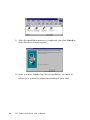
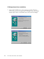
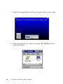
9. After the installation process is completed, just click Finish to
close the driver setup program.
10. After you have finished the driver installation, you need to
reboot your system for proper functioning of your card.
22
PCI Comm Card Series User's Manual
Reboot your system after Win95/98 driver
Setup
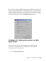
PCI UARTs Device Driver Installation
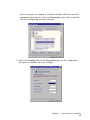
1. On rebooting your system, Windows 95/98 will recognize your
card devices and will search for the device driver for PCI UARTs
automatically as shown in the following dialog box.
2. Choose “Search for the most Suitable Driver” radio button, and
click Next.
Chapter 3
Driver Setup & Installation
23
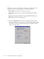
3. You don’t have to choose the location of the device driver
program, since it is already installed on your system. Just click
Next to proceed.
4. Windows 95/98 has found the driver location and is ready to
install the driver. Click Next.
24
PCI Comm Card Series User's Manual
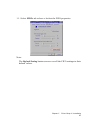
5. You will be prompted to decide whether you want to install the
Updated Driver. Accept the Updated Driver option and click Next.
6. The driver installation is complete. Click Finish.
Chapter 3
Driver Setup & Installation
25
PCI Bridge Device Driver Installation
7. After the PCI UARTs device driver has been installed, Windows
95/98 will proceed to recognize the PCI Bridge device. Just repeat
similar steps as above to install the device driver for PCI Bridge.
26
PCI Comm Card Series User's Manual
8. After the PCI Bridge device driver is installed, a dialog box such
as below will appear to indicate that Windows 95/98 has completed the device driver installation of the hardwares.
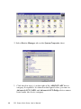
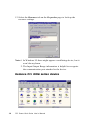
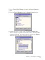
Verify your Win95/98 Driver Setup
After you have installed your card, go to Control Panel/System/
Device Manager to look for the Device Name that is supposed to
appear after you have installed the driver.
Chapter 3
Driver Setup & Installation
27
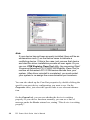
Note:
If your device has not been properly installed, there will be an
exclamation mark (!) on the device name to indicate a
conflicting device. If this is the case, just remove that device
and start the driver installation process all over again. Or you
can run COM Registry Clean Tool utility (by accessing Start/
Programs/Advantech PCI ICOM/COM Registry Clean Tool) to
remove all Advantech PCI ICOM series devices from your
system. After driver uninstall is completed, you must restart
your system to re-assign the communication port numbers.
You can also check up the Com Port properties by double-clicking the
specific com port device configuration you want to see. On the
Properties sheet, just select the specific tabs to see relevant information.
On the General tab, you can see whether the device is working
properly. If your device functions normally, you can see a line of
message under the Device statsus box, stating “This device is working
properly”.
28
PCI Comm Card Series User's Manual
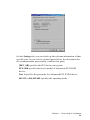
On the Settings tab, you can check up the relevant information of that
specific port. As you can see on the figures below, the description for
the communication port actually contains four parts:
[DEV_0B] specifies the PCI slot in your system.
PCI-1620 specifies the device model of Advantech PCI ICOM
device.
Port 1 specifies the port index for Advantech PCI ICOM device.
RS-232 or RS-422/485 specifies the operating mode.
Chapter 3
Driver Setup & Installation
29
30
PCI Comm Card Series User's Manual
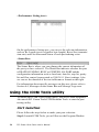
If you want to configure FIFO Properties, select FIFOs tab. On the tab,
you can see the relevant FIFO configurations. We recommend you to
use the default settings. However, you are allowed to set the configurations manually according to your preferences. If you want to restore
the default settings, just click the Default Setting button.
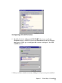
Configure PCI ICOM serial devices on Windows 95/98
After your serial devices have been properly installed in your
system, you can now proceed to configure your serial devices
according to the following steps:
1. Access Control Panel/System
Chapter 3
Driver Setup & Installation
31
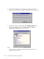
2. Select Device Manager tab on the System Properties sheet.
3. Click the plus sign (+) on the right of the ADSPCIUART device
category to expand it. As shown on the figure below, you can see
Advantech PCI UARTs and Advantech PCI Bridge device names
listed under the device category.
32
PCI Comm Card Series User's Manual
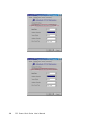
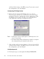
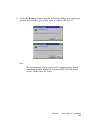
Configuring PCI UARTs Device
4. Double-click the Advantech PCI UARTs device to evoke its
Properties page, and then select the Resource tab on the Properties page to look up or configure the current settings of the PCI
UARTs device.
5. After you have made necessary changes or if you are just satisfied
Chapter 3
Driver Setup & Installation
33
with the default settings, click OK to accept. If you want to cancel
the configuration, just click Cancel.
Configuring PCI Bridge Device
6. Double-click the Advantech PCI Bridge device to evoke its
Properties page, and then select the Resources tab on the Properties page to look up or configure the current configuration of the
PCI Bridge device to make sure there is no conflicting device.
Click other tabs to look up or configure the device.
Note: 1. In Windows 95 there might appear a conflicting device, but
it won’t do any harm.
2. The Input/Output Range information is helpful to recognize
the communication port attached to the device.
7. After you have made necessary changes or if you are just satisfied
with the default settings, click OK to accept. If you want to cancel
the configuration, just click Cancel.
Configuring ports
8. Click the plus sign (+) on the right of the Ports (COM & LPT)
34
PCI Comm Card Series User's Manual
device category to expand it, and then double-click the specific
communication port to evoke its Properties page. Select specific
tabs for configuring specific settings.
9. Select the Settings tab on the Properties page of the communica
tion port to examine the port settings.
Chapter 3
Driver Setup & Installation
35
Note: As you can see on the figure of the previous page above, the
description for the communication port contains four parts:
[DEV_0B] specifies the PCI slot in your system.
PCI-1620 specifies the device model of Advantech PCI ICOM
device.
Port 1 specifies the port index for Advantech PCI ICOM device.
RS-232 specifies the operating mode.
10. Select the Data Rate tab to check up information about clock
frequency, baud rate, etc. You can see a slider on the bottom of this
tab, and if you want to adjust the baud rate, just drag the slider to
where you want it to be.
36
PCI Comm Card Series User's Manual
11. Select FIFOs tab to have a look at the FIFO properties.
Note:
The Default Setting button can recover all the FIFO settings to their
default values.
Chapter 3
Driver Setup & Installation
37
12. Select the Resource tab on the Properties page to look up the
resource settings.
Note:1. In Windows 95 there might appear a conflicting device, but it
won’t do any harm.
2. The Input/Output Range information is helpful to recognize
the communication port attached to the device.
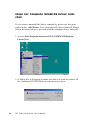
Remove PCI ICOM series device
38
PCI Comm Card Series User's Manual
1. Access Control Panel/System to bring up the System Properties
sheet.
2. Select the Device Manager tab on the System Properties sheet.
3. Click the plus sign (+) on the right of the Ports (COM & LPT)
device category to expand it. Select the specific “Advantech PCI
communication port” you want to remove, and click the Remove
button to remove the device you have selected.
Chapter 3
Driver Setup & Installation
39
4. The following dialog box will appear to prompt you again to
make sure you really want to remove the device from your system.
5. Click the plus sign (+) on the right of the ADSPCIUART device
category to expand it, and select Advantech PCI UARTs or
Advantech PCI Bridge you want to remove.
Note:
You must remove all ports attached to the device before you
remove the device itself.
40
PCI Comm Card Series User's Manual
6. Click the Remove button and the following dialog box appears to
prompt you whether you really want to remove the device.
Note:
We recommend you to remove the original device before
installing another model of Advantech PCI ICOM series
device in the same PCI slot.
Chapter 3
Driver Setup & Installation
41
Steps for Complete Win98/98 Driver Uninstall
If you want to uninstall the driver completely, please use the uninstaller utility, AdsCleaner, for a clean and safe driver uninstall. Please
follow the steps below to proceed with the complete driver uninstall:
1. Access Start/Program/Advantech PCI ICOM/COM Registry
Clearn Tool.
2. A dialog box will appear to make sure that you want to remove all
the Advantech PCI ICOM devices from your system.
42
PCI Comm Card Series User's Manual
3. Click OK to begin removal of all PCI ICOM devices from your
system. After the removal is complete, a message box will appear
to prompt you for a reboot.
Windows NT Driver Setup
Windows NT supports up to 256 serial ports, from COM1 to
COM256. Advantech PCI ICOM driver, however, will start to assign
port numbers beginning from COM 5. In order to fully utilize
Windows NT advanced features such as multi-process and multithread, we offer pure 32-bit Windows NT device drivers for the PCI1601/ 1602/ 1610/ 1612/ 1620 multiport cards. All these drivers
conform to Win32 COMM API standard.
Steps for Windows NT Driver Setup
Before you install the card into your system, we recommend you
install the driver first. Please follow the steps below for the PCI- 1601/
-1602/ -1610/-1612/ -1620 Windows NT driver installation.
1. Insert your companion CD-ROM disc into your CD-ROM drive.
2. The driver setup program will be launched automatically. If the
autoplay function is not enabled on your system, use Windows
Explorer or Windows Run command to execute SETUP.EXE on the
companion CD-ROM.
Chapter 3
Driver Setup & Installation
43
3. After the setup program is launched, you’ll see the following Setup
Screen.
4. Click the Next button and the License Agreement page appears.
5. Click Yes to accept the terms as stated in the License Agreement.
The Select Program Folder dialog box appears.
44
PCI Comm Card Series User's Manual
6. Just click Next to accept the default installation folder, and the
Start Copying Files dialog box appears. (Or you can specify the
folder name yourself, and then click Next). On the dialog box you
can survey your current installation settings. If you are satisfied
with these current settings,, just click Yes to complete your driver
installation. If you are not satisfied with the settings, just click
Back to return to the previous steps and go over again.
Chapter 3
Driver Setup & Installation
45
7. The Driver Setup Program will begin copying files to your system
8. The Setup program will create the Advantech ICOM Tools folder
in the Start Menu.
46
PCI Comm Card Series User's Manual
9. After the installation process is completed, just click Finish to
close the driver setup program.
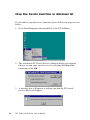
Start the Device Function in Windows NT
After you have properly installed the driver, please start the function
of your hardware device by the following steps:
1. Go to Start/Programs/Advantech PCI Comm Tools/COM Service
Startup Tool.
Chapter 3
Driver Setup & Installation
47
2. The Advantech PCI Serial Service Manager dialog box appears.
Choose to start your serial service by selecting the Start radio
button and click OK.
3. A message box will appear to inform you that the PCI serial service
has started successfully.
Verify your NT driver Setup
After you have installed your card, go to Control Panel/Port to look
for the Com port name that is supposed to appear after you have
installed the driver. (This section should be verified with Andrew!)
48
PCI Comm Card Series User's Manual
For proper functioning of the card, the Advantech PCI Serial Driver
service must be started, too. If your card cannot function properly,
please look into Control Panel/Devices to see if the Advantech PCI
Serial Driver service is started.
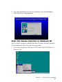
Verify your NT Driver Function
You can verify the driver function by the Windows NT Diagnostics
utility. As you can see on the Services tab, the status of the Advantech
PCI serial driver is currently running. This indicates that the driver
functions properly.
Chapter 3
Driver Setup & Installation
49
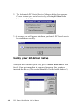
Stop the Device Function in Windows NT
If you want to stop the device function, please follow the steps as seen
below:
1. Go to Start/Programs/Advantech Driver for NT/AdsStart.
2. The Advantech PCI Serial Service Manager dialog box appears.
Choose to stop your serial service by selecting the Stop radio
button and click OK.
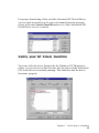
3. A message box will appear to inform you that the PCI serial
service has been stopped.
50
PCI Comm Card Series User's Manual
CHAPTER
ICOM Tools
4
Chapter 4
ICOM Tools
Introduction
Advantech ICOM Tools is a very convenient utility to help you test
the performance of ICOM card through port status analysing. It
features a Graphical User Interface as easy to use as you will soon get
familiar with all the menu commands and toolbar buttons. Advantech
ICOM Tools is applicable to all series of Advantech ICOM cards, even
to other third-party ICOM cards. It is included for free on the diskette
or on the companion CD-ROM with all the Advantech ICOM cards.
Installation
To begin its installation, just double-click the SETUP.EXE program to
launch the ICOM Tools Setup program. The Setup program will copy
the program files to the destination folder you choose or to a default
installation path (i.e. C:\program files\Advantech\ICOM Tools) if you
didn’t specify. A program folder will be created in your Start/
Programs menu. (Later you can just access the program through
Start/Program/Advantech PCI Comm Tools/COM Examine Tool)
User Interface of ICOM Tools
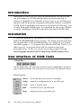
<Menu Bar >
On the Menu Bar you can select various menu commands to perform
port-testing functions. You can also use access key for quicker action.
Port Submenu
52
Select
select the ports you want to configure.
Setup
setup the configuration of a specific port
Close
close a specific port
Run
run the test on a specific port
Stop
stop the test on a specific port
PCI-Comm Card Series User's Manual
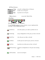
All Ports Submenu
Setup
setup the configurations of all ports
Run
run the test on all ports
Stop
stop the test on all ports
Help submenu
access the Online Help
<Tool Bar>
(for specific port) (for all ports)
Using Tool Bar buttons is a more intuitive way to implement the
functions of the ICOM Tools utility.
Port Select
select the port(s) you want to perform test on
Port Setup
setup configuration of the port you have selected
Port Close
close the port you have selected
Port Run
run the port test on the port you have selected
Port Test
stop the test on the port you have selected
All Ports Setup Setup the configuration of all ports not running
test
All Ports Run
run test on all ports
Chapter 4
ICOM Tools
All Ports Stop
stop test on all ports
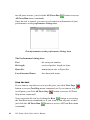
Clear Message clear messages on Message Logo area and the Rx
length information on the Performance Listing
area
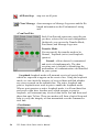
<Com Port Tab>
Each Com Port tab represents a specific port
you have selected for test and configuration.
On the tab, you can see the Transfer Mode,
Port Status, and Message Logo area.
Transfer Mode
You can specify the transfer mode to be
Normal, loopback (active) and loopback
(passive)
Normal—allows data to be transmitted
and received simultaneously. The data
receiving rate is helpful in identifying the
performance of communication card installed
on your system.
Loopback-loopback mode will transmit a series of special data,
which are expected to appear on the receive line. Using the loopback
mode, we can check the integrity of received data and find whether
any error occurred on the transmit line. The active loopback and
passive loopback must work in pair to enable the loopback mode.
When a port operates as active loopback mode, it will send data first
and receive data later. Another port, which operates as passive
loopback, will retransmit any received data on Rx line and then send
these data onto Tx line. These two modes will form a logical loop and
help to verify the integrity of data transmitted over the communication link.
<Port Status>
DTR
54
(data-terminal-ready)
PCI-Comm Card Series User's Manual
DSR
(data-set-ready)
RTS
(request-to-send)
CTS
(clear-to-send)
CD
(carrier-detect)
For RS-232 specifications, DTR and RTS are for output signals and
can be toggled on and off simply by double-clicking legends (such as
DTR, DSR, RTS, CTS, CD) under the red/green marks. But if your are
using RTS/CTS for flow control to run the test, you will see the RTS
mark appear as black. This indicates that the RTS can no longer be
toggled on/off since it is now controlled by driver itself.
A black mark represents the function is controlled by driver itself
and therefore not controllable by software utility.
<Message Logo>
On the Message Logo area, you can see the relevant messages about
the port(s) you have selected.
For information about specific messages in this area, please refer to
Section 4.4, Messages on the Status Bar and Message Logo area.
<Tx Slide Bar>
The Tx Slide Bar allows you to check the overall system loading. You
can adjust the transmission rate of your port(s) from 0% to 100%. Just
drag the slide button along the groove to adjust the transmission rate.
Chapter 4
ICOM Tools
<Performance Listing Area>
On the performance listing area, you can see the relevant information,
such as Rx Length (received packet byte length), Bytes/Sec (transmission rate) and Last Abnormal Status of each port running a test.
<Status Bar>
The Status Bar is where you can glimpse the current information of
the port you have selected. The Status Bar indicates whether the port
is READY, RUNNING, BUSY or STOPPED, N/A PORT and the
configuration information such as baud rate, data bit, stop bit, parity
bit and flow control (represented as 1200 N 8 1 None) settings. Also
we can see the duration of the test in hh:mm:ss format on the right.
For information about specific messages on this area, please refer to
Section 4.4, Messages on the Status Bar and Message Logo area.
Using the ICOM Tools utility
To launch the ICOM Tools testing utility, just access Start/Programs/
Advantech PCI Comm Tools/COM Examine Tools to start the port
testing utility.
Port Selection
Please follow the steps below to make your port selection:
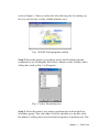
Step1: Launch ICOM Tools, you will first see the Program Window
56
PCI-Comm Card Series User's Manual
such as Figure 1. Since you haven’t selected any port for testing yet,
all you can see now is only a blank window area.
Fig. 1 ICOM Tools program window
Step 2:Select the port(s) you want to test by the Port/Select menu
command or by clicking the Port Select button on the Toolbar, and a
dialog box such as Fig. 2 will appear.
Fig. 2 Select Port dialog box
Step 3: Select the port(s) you want to perform test on from the Port
checkbox group. You can either click the checkbox or double-click
the name(s) of the port(s) to select/deselect port(s) to perform test. The
Chapter 4
ICOM Tools
port(s) you selected will immediately appear in the Selected Port
field.
Fig. 3 Ports you selected will appear in the Selected Port
checkbox group.
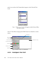
Step 4: Click OK to bring up the ICOM Tools User Interface such as
below:
Tx Silde Bar
Menu Bar
Tool Bar
Com Port Tab
Performance Listing
Transfer Mode
Port Status
Message Logo
Status Bar
Fig. 4 ICOM Tools User Interface
4.3.2 Configure the Port
58
PCI-Comm Card Series User's Manual
You can choose to configure a specific port (or to configure all ports)
before running your test. Just click a Com Port Tab to select the port
you want to configure, and then click the Port Setup
button or
just access the Port/Setup menu command (or if you want to configure all ports at once, just click the All Ports Setup
button or
access the All Ports/Setup menu command) to bring up the Configure
Port dialog box such as below.
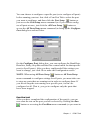
On the Configure Port dialog box, you can configure the Baud Rate,
Data bits, Parity, Stop Bits and the flow control mode for that specific
port (or for all ports). After you have configured all the settings you
want to change, just click Ok to make this configuration active.
NOTE: When using All Ports Setup
button or All Ports/Setup
menu command to configure settings for all ports, you must take care
to stop any ports that are running test in order to configure them. If
you do not stop the test running on a specific port, it won’t be
configured at all. That is, you get to configure only the ports that
have been stopped.
Run the test
After you have completed the configuration of the port(s), you can
now start the test on the port you have selected by clicking the Run
button or accessing the Port/Run menu command (or you want to
Chapter 4
ICOM Tools
run all ports at once, just click the All Ports Run
All Ports/Run menu command).
button or access
Once the test is started, you can see relevant test information of port
performance on the performance listing area.
Test information on the performance listing Area
The Performance Listing Area
Port
the com port number
Rx length
received packet length in bytes
Bytes/Sec
transmission rate in Bytes/Sec
Last Abnormal Status
last abnormal status
Stop the test
If you want to stop the test on a specific port, just click Port Stop
button or access Port/Stop menu command (or if you want to stop test
on all ports, just click All Ports Stop
button or access All Ports/
Stop menu command).
You can restart the test by clicking the Run
button or accessing
the Port/Run menu command (or if you want to run all ports at once,
just click the All Ports Run
button or access All Ports/Run menu
command).
60
PCI-Comm Card Series User's Manual
Close Port
If you want to close a port, just select the Com Port tab and click Port
Close
port.
button or access Port/Close menu command to close the
Exit the ICOM Tools utility
To exit the ICOM Tools utility, simple access Port/Exit menu command or click the Close button on the upper right corner of the
program window.
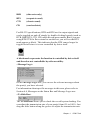
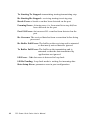
Messages on the Status Bar and
Message Logo area
Messages appearing on the Status Bar and Message Logo area are
helpful in understanding specific information of your system settings
and performance.
Status Bar messages
BUSY: the port is currently used by other application.
FAIL: the configuration parameters are not accepted by the port
N/A PORT: the port is not available in the system
READY: the port is ready to run or configure.
RUNNING: the test is running on the port
STOPPED: the test running on the port has been stopped by user
Message Logo messages
Port Opened: Users has opened the port
Port Setup Fail: Users set up port configuration with parameters
that are either incorrect or unsupported.
Port Running: The port is running test
Port Stopped: The test is stopped on the port
Chapter 4
ICOM Tools
Tx Starting/Tx Stopped: transmitting starting/transmitting stop
Rx Starting/Rx Stopped : receiving starting/receiving stop
Break Error: a break event has been detected on the port
Framing Error: A timing error (i.e. from start bit to stop bit) has
been detected on the port
Port I/O Error: An incorrect I/O event has been detected on the
port
Rx Overrun: The received data has been overwritten before being
processed
Rx Buffer Full Error: The buffer on the receiving end is saturated
so that newly arrived data are ignored
Tx Buffer Full Error: The buffer on the transmitting end is
saturated so that the data transmitted by
applications are ignored.
LB Error - %d: data error is detected in loop back
LB Rx Pending: Loop back mode is waiting for incoming data
Data Setup Error: parameter error in port configuration
62
PCI-Comm Card Series User's Manual
CHAPTER
5
Pin Assignment &
Wiring
Chapter 5 Pin Assigment & Wiring
63
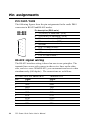
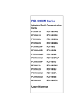
Pin assignments
PCI-1601/1602
The following figures show the pin assignments for the card's DB-9
connectors in RS-422 and RS-485 modes.
RS-422
RS-485
1
6
2
9
1
TX-(DATA-) or send data - (DTE)
2
TX+(DATA+) or send data + (DTE)
3
RX+ or receive data + (DTE)
4
RX - or receive data - (DTE)
5
GROUND
3
6
RTS - or ready to send -
4
7
RTS+ or ready to send +
5
8
CTS+ or clear to send +
9
CTS- or clear to send -
7
8
Pin description (DB-9 male)
RS-422 signal wiring
The RS-422 interface wiring is based on one-to-one principles. The
transmit lines on one side connect to the receive lines on the other
side, and vice versa. With RS-422, you can transmit and receive data
simultaneously (full duplex). The connections are as follows:
64
PCI-1601/1602 DTE (Male DB-9)
Terminal DTE
Pin
1
Signal
TxD-
Signal
RxD-
2
TxD+
RxD+
3
RxD+
TxD+
4
RxD-
TxD-
5
GND
GND
6
RTS-
CTS-
7
RTS+
CTS+
8
CTS+
RTS+
9
CTS-
RTS-
PCI-Comm Card Series User's Manual
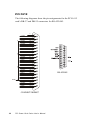
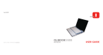
PCI-1610/1612
The following diagrams show the pin assignments for the PCI-1610/
1612 card's DB-37 and DB-25 connectors for RS-232.
Chapter 5 Pin Assigment & Wiring
65
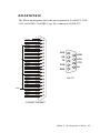
PCI-1612
The following diagrams show the pin assignments for the PCI-1612
card's DB-37 and DB-25 connectors for RS-422/485.
CTS2TX2RX2RTS2CTS2+
RTS2+
TX2+
RX2+
CTS3TX3RX3RTS3CTS3+
RTS3+
TX3+
RX3+
CTS1TX1RX1RTS1CTS1+
RTS1+
TX1+
RX1+
CTS0TX0RX0GND
RTS0CTS0+
RTS0+
TX0+
RX0+
1
20
2
21
3
22
4
23
5
24
6
25
7
26
8
27
9
28
10
29
11
30
12
31
13
32
14
33
15
34
16
35
17
36
18
37
19
CONNECTOR DB37
66
PCI-Comm Card Series User's Manual
RS-422/485
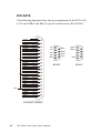
PCI-1610/1612
The following diagrams show the pin assignments for the PCI-1610/
1612 card's DB-37 and DB-9 (opt 4A) connectors for RS-232.
CTS2TX2RX2RTS2CTS2+
RTS2+
TX2+
RX2+
CTS3TX3RX3RTS3CTS3+
RTS3+
TX3+
RX3+
CTS1TX1RX1RTS1CTS1+
RTS1+
TX1+
RX1+
CTS0TX0RX0GND
RTS0CTS0+
RTS0+
TX0+
RX0+
1
20
2
21
3
22
4
23
5
24
6
25
7
26
8
27
9
28
10
29
11
30
12
31
13
32
14
33
15
34
16
35
17
36
18
37
19
DCD
DSR
RX
RTS
TX
CTS
DTR
RI
GND
RS-232
CONNECTOR DB37
Chapter 5 Pin Assigment & Wiring
67
PCI-1612
The following diagrams show the pin assignments for the PCI-1610/
1612 card's DB-9 and DB-25 (opt 4A)connectors for RS-422/485.
CTS2TX2RX2RTS2CTS2+
RTS2+
TX2+
RX2+
CTS3TX3RX3RTS3CTS3+
RTS3+
TX3+
RX3+
CTS1TX1RX1RTS1CTS1+
RTS1+
TX1+
RX1+
CTS0TX0RX0GND
RTS0CTS0+
RTS0+
TX0+
RX0+
1
20
2
21
3
22
4
23
5
24
6
25
7
26
8
27
9
28
10
29
11
30
12
31
13
32
14
33
15
34
16
35
17
36
18
37
19
TX-
RTS+
RX+
CTS-
GND
PCI-Comm Card Series User's Manual
DATADATA+
CTS+
RX-
CONNECTOR DB37
68
RTS-
TX+
RS-422
GND
RS-485
PCI-1620
RS-232 8-port connection boxes/octopus cable designed for PCI-1620
are:
Opt8A:
Opt8B:
Opt8C:
8-port DB25 female connection box
8-port DB25 male connection box
Octopus cable with 8 male RS-232 DB25 ports
The following lists the pin assignments of the DB62 connector on the
bracket. You may fabricate octopus cable for DB25 to 8 x DB25 with
these pinouts.
Pin no.
Signal
Pin no.
Signal
Pin no.
Signal
1
TxD1
22
RxD1
43
CTS1
2
DTR1
23
DSR1
44
RTS1
24
DCD1
45
GND
3
RxD2
25
TxD2
46
CTS2
4
DSR2
26
DTR2
47
RTS2
5
DCD2
6
TxD3
27
RxD3
48
CTS3
7
DTR3
28
DSR3
49
RTS3
29
DCD3
50
GND
8
RxD4
30
TxD4
51
CTS4
9
DSR4
31
DTR4
52
RTS4
10
DCD4
32
GND
11
RxD5
33
TxD5
53
CTS5
12
DSR5
34
DTR5
54
RTS5
13
DCD5
55
GND
14
TxD6
35
RxD6
56
CTS6
15
DTR6
36
DSR6
57
RTS6
37
DCD6
58
GND
16
RxD7
38
TxD7
59
CTS7
17
DSR7
39
DTR7
60
RTS7
18
DCD7
40
GND
19
RxD8
41
TxD8
61
CTS8
20
DSR8
42
DTR8
62
RTS8
21
DCD8
Chapter 5 Pin Assigment & Wiring
69
DB25
Pinout
DB9
Pinout
Ground
7
5
TD
Transmit Data
2
3
Output
RTS
Request To Send
4
7
Output
DTR
Data Terminal Ready
20
4
Output
RD
Receive Data
3
2
Input
CTS
Clear To Send
5
8
Input
DSR
Data Set Ready
6
6
Input
DCD
Data Carrier Detect
8
1
Input
Ring Indicator
22
9
Input
Signal
GND
RI
70
Name
PCI-Comm Card Series User's Manual
Mode
Wiring
RS-232 signal wiring
Since the RS-232 interface is not strictly defined, many devices have
their own connection methods which may ignore some signal lines or
define reserved lines for other functions. It is best to refer to the user’s
manual for your device for installation instructions. You may find the
following helpful.
In general, DTE (Data Terminal Equipment) refers to the device that is
leading the communication. Examples include PC’s, terminals and
some printers. DCE refers to the device being communicated with or
controlled. Examples include modems, DSU’s (digital service units),
printers and lab/factory equipment.
In some situations you may be able to get by with just three lines:
data on TXD, a signal ground and a handshaking line. Examples are
printer or plotter connections, troubleshooting and situations where
you require only one-wire communication.
Terminal or PC (DTE) connections
DB-25 Male
DB-25 Male or Female:
Terminal
Pin
2
Signal
TxD
Pin
3
Signal
RxD
3
RxD
2
TxD
4
RTS
5
CTS
5
CTS
4
RTS
6
DSR
20
DTR
7
GND
7
GND
20
DTR
6
DSR
8
DCD
8
DCD
Chapter 5 Pin Assigment & Wiring
71
Modem connections
DB-25 Male
Modem (DCE)
Pin
2
Signal
TxD
Pin
2
Signal
RxD
3
RxD
3
TxD
4
RTS
4
CTS
5
CTS
5
RTS
6
DSR
6
DTR
7
GND
7
GND
20
DTR
20
DSR
8
DCD
8
DCD
For DTE to DCE connections, use straight through cable (i.e., you
don't have to reverse lines 2 and 3, lines 4 and 5, and lines 6 and 20
since, in general, the DCE RS-232 interfaces are reversed themselves).
Terminal without handshake
DB-25 Male
Terminal, PC (DTE)
Pin
2
Signal
TxD
Pin
3
Signal
RxD
3
RxD
2
TxD
4
5
RTS
CTS
7
GND
—
—
7
GND
6
20
8
DSR —
DTR —
DCD —
Therefore, if you are not using CTS, RTS, DSR ,DTR and DCD
signals, please short pins 4 and 5 together, and please short pins 6, 8,
and 20 together.
72
PCI-Comm Card Series User's Manual
RS-422 signal wiring
The RS-422 interface wiring is based on one-to-one principles. The
transmit lines on one side connect to the receive lines on the other
side, and vice versa. With RS-422, you can transmit and receive data
simultaneously (full duplex). The connections are as follows:
DTE (Male DB-9)
Terminal DTE
Pin
1
Signal
TxD-
Signal
RxD-
2
TxD+
RxD+
3
RxD+
TxD+
4
RxD-
TxD-
5
GND
GND
6
RTS-
CTS-
7
RTS+
CTS+
8
CTS+
RTS+
9
CTS-
RTS-
Terminator Resistors setup
The signals DSR, DTR and DCD are shorted internally on the PCI1601/1602/1612 cards when operating in RS-422 mode.
A user can solder in termination resistors if necessary for impedance
matching. The card has two mounting spaces for termination resistors,
but no resistors are installed at the factory. Each pair of signal lines
has a separate resistor (RxD+/-, TxD+/-).
Chapter 5 Pin Assigment & Wiring
73
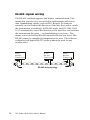
RS-485 signal wiring
The RS-485 standard supports half-duplex communication. This
means that just two wires are needed to both transmit and receive
data. Handshaking signals (such as RTS, Request To Send) are
normally used to control the direction of the data flow and to switch
the transmission accordingly. In RS-485 mode, the PCI-1601/1602/
1612 automatically senses the direction of the data flow and switches
the transmission direction — no handshaking is necessary. This
means a user can build an RS-485 network with just two wires. This
RS-485 control is completely transparent to the user. The Software
written for half duplex RS-232 works without the need for any
modification.
D.T.E
RS-485
Transceiver
D.T.E
RS-485
Transceiver
RS-485 wiring topology
74
PCI-Comm Card Series User's Manual
D.T.E
RS-485
Transceiver
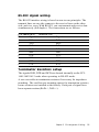
Termination resistor setup
You can install termination resistors if necessary for impedance
matching. The card has mounting spaces for termination resistors, but
no resistors are installed at the factory. Depending on your application you may need to solder in a single resistor to handle the DATA+/
DATA- pair (and a corresponding resistor on the other end of the
connection). The value of the resistor should equal the characteristic
impedance of the signal wires (approximately 120 Ohms or 300
Ohms).
Chapter 5 Pin Assigment & Wiring
75
APPENDIX
A
Register structure
and format
Appendix A
Register Structure and Format
73
Register Structure
This appendix gives short descriptions of each of the module's
registers. For more information please refer to the data book for the
STARTECH 16C550 UART chip.
All registers are one byte. Bit 0 is the least significant bit, and bit 7 is
the most significant bit. The address of each register is specified as an
offset from the port base address (BASE), selected with DIP switch
SW1 or SW2.
DLAB is the "Divisor Latch Access Bit:, bit 7 of BASE+3.
BASE+0 Receiver buffer register when DLAB=0 and the operation
is a read.
BASE+0 Transmitter holding register when DLAB=0 and the
operation is a write.
BASE+0 Divisor latch bits 0 - 7 when DLAB=1.
BASE+1 Divisor latch bits 8 - 15 when DLAB=1
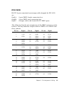
The two bytes BASE+0 and BASE+1 together form a 16-bit number,
the divisor, which determines the baud rate. Set the divisor as follows:
74
Baud rate
50
Divisor
2304
Baud rate
3600
Divisor
32
75
1536
4800
24
150
768
7200
16
300
384
9600
12
600
192
19200
6
1200
96
38400
3
1800
64
57600
2
2400
48
115200
1
PCL-743/745 Series User's Manual
BASE+1
BASE+2
BASE+3
Interrupt Status Register (ISR) when DLAB=0
Bit 0
Enable received-data-available interrupt
bit 1
Enable transmitter-holding-register-empty
interrupt
bit 2
Enable receiver-line-status interrupt
bit 3
Enable modem-status interrupt
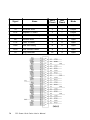
FIFO Control Register (FCR)
bit 0
Enable transmit and receive FIFOs
bit 1
Clear contents of receive FIFO
bit 2
Clear contents of transmit FIFO
bits 6-7
Set trigger level fro receiver FIFO interrupt.
Bit 7
0
Bit 6
0
FIFO trigger level
01
0
1
04
1
0
08
1
1
14
Line Control Register (LCR)
bit 0
Word length select bit 0
bit 1
Word length select bit 1
Bit 1
0
Bit 0
0
Word length (bits)
5
0
1
6
1
0
7
1
1
8
bit 2
Number of stop bits
bit 3
Parity enable
bit 4
even parity select
bit 5
Stick parity
bit 6
Set break
Appendix A
Register Structure and Format
75
bit 7
BASE+4
BASE+5
Divisor Latch Access Bit (DLAB)
Modem Control Register (MCR)
bit 0
DTR
bit 1
RTS
Line Status Register (LSR)
bit 0
Receiver data ready
bit 1
Overrun error
bit 2
Parity error
bit 3
Framing error
bit 4
Break interrupt
bit 5
Transmitter holding register empty
bit 6
Transmitter shift register empty
bit 7
At least one parity error, framing
error or break
indication in the FIFO
BASE+6
BASE+7
76
Modem Status Register MSR)
bit 0
Delta CTS
bit 1
Delta DSR
bit 2
Trailing edge ring indicator
bit 3
Delta received line signal detect
bit 4
CTS
bit 5
DSR
bit 6
RI
bit 7
Received line signal detect
Temporary data register
PCL-743/745 Series User's Manual
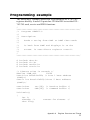
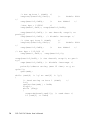
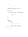
Programming example
The following C example shows how to program the PCL-743/745
registers directly. It uses I/O ports hex 3F8 and 2F8 to test the PCL743/745 send, receive and FIFO functions.
/
***************************************************/
/* Program: DEM001.C
*/
/* Description:
*/
/*
Sends a string from COM1 to COM2 then reads
*/
/*
it back from COM2 and displays it on the
*/
/*
screen. It uses direct register control.
*/
/
***************************************************/
#
#
#
#
include
include
include
include
<dos.h>
<io.h>
<stdio.h>
<conic.h>
/* Timeout value in seconds */
#define TIME_OUT
10000
static int base0=0x3f8; /* Port 1 base address
(COM1)*/
static int base1=0x2f8;/*Port 2 base address
(COM2)*/
static char
static char
rec[16]; /* Receive buffer */
CMD[16]; /* Command buffer */
Void main()
{
int i;
timeout; /*
char flag;
counter for timeout */
Appendix A
Register Structure and Format
77
/* Set up Port 1 (COM1) */
outport((base0+2),0xc9);
/*
outp(base1+3,0x80);
Set DLAB=1
Enable FIFO
*/
/*
*/
/*Set bps = 115200
*/
outp(base0 ,0x01); outp(base0+1,0x00);
outp(base0+3,0x03); /* set data=8; stop=1; no
parity*/
outp(base0+1,0x00); /* disable interrupt */
/* (Set up) Port 2 (COM2)
outport((base1+2),0xc9);
*/
/*
outp(base1+3,0x80);
Set DLAB=1
Enable FIFO
*/
/*
*/
/* Set bps = 115,200 */
outp(base1 ,0x01); outp(base1+1,0);
outp(base1+3,0x03); /* Set data=8; stop=1; no parity*/
oupt(base1+1,0x00); /* Disable interrupt */
printf(:\nEnter string (max 15 char) or Q to
quit:");
gets(cmd);
while (cmd{0} != 'q' && cmd[0] != 'Q')
{
/* Send string on Port 1 (COM1)
*/
i=0;
cmd[strlen(cmd)] = 0x0d;
flag=1;
while (flag)
{
outportb(base0,cmd[i]); /* send data */
if (cmd[i] == 0x0d;
78
PCL-743/745 Series User's Manual
*/
if (cmd[i] == 0x0d)
flag=0
i++;
}
/* Receive data on Port 2 (COM2) */
i=0;
flag=1;
timeout=TIME_OUT;
whole (flag)
{
rec[i]=inportb(base1); /* Receive data*/
if (rec[i] == 0x0d)
{
rec[i=1]='\0';
flag=0;
printf("\nReceived data: %s\n", rec);
}
i++;
{
}
else
/I Check timeout */
timeout-;
if(timeout == 0)
{
flag=0;
print("\nTimeout error\n");
}
}
} /*
End of receive data while()
*/
printf("\nEnter string (max 15 char) or Q to
quit:");
gets(cmd);
} /*End of "Enter string"while() */
}
/*End of main()
*/
Appendix A
Register Structure and Format
79
80
PCL-743/745 Series User's Manual
APPENDIX
PC I/O address
reference
Appendix B
B
PC I/O Address Reference
81
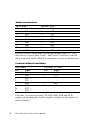
The following table shows the I/O addresses commonly used by
standard PC devices. Avoid these addresses when you select your
port I/O base addresses.
I/O Address
000 - 00F
82
Device
DMA (8237A)
020 - 021
8259A IRQ Controller
040 - 043
8253/8254 Timer/Counter
060 - 063
PPI 8255A
070 - 071
Real-Time Clock
080 - 08F
DMA Page Register
0A0 - 0BF
8259A Interrupt Chip
0C0 - 0DF
Second DMA Controller 8237A
0F0 - 0FF
Math Coprocessor
1F0 - 1F8
AT Fixed Disk
200 - 20F
Game I/O
278 - 27F
Serial I/O Port #2
2F8 - 2FF
Serial Adaptor ( COM 2 )
320 - 32F
XT Fixed Disk
378 - 37F
Parallel Printer Adaptor
380 - 38F
SDLC Binary Communication Adaptor
3A0 - 3AF
Master Binary Communication Adaptor
3B0 - 3BF
Monochrome/Parallel Adaptor
3D0 - 3DF
Color Graphics Adaptor
3F0 - 3F7
Diskette Controller
3F8 - 3FF
Serial Adaptor ( COM 1 )
PCL-743/745 Series User's Manual