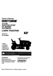
1
Owner's Manual
ELECTRIC
START
38" MOWER
5 SPEED TRANSAXLE
LAWN TRACTOR
Model No.
917.259870
•
•
•
•
Safety
Assembly
Operation
Maintenance
• Repair Parts
differently from previously built engines. Before you start the enThis product has a low emission engine which operates
gine, read and understand this Owner's Manual.
CAUTION:
Read and follow all Safety
Rules and Instructions before
operating
Sears,
this equipment.
Roebuck and Co., Hoffman
For answers to your questions
about this product, Call:
1-800-659-5917
Sears Craftsman Help Line
5 am - 5 prn, Mon - Sat
Estates, II 60179
Visit our Craftsman website:www.sears.com/craftsman
Warranty ...............................................
2
Safety Rules .........................................
3
Product Specifications .......................... 6
Assembly ..............................................
8
Operation ............................................
11
Maintenance Schedule ...................... 17
LIMITED ONE YEAR WARRANTY
Maintenance .......................................
17
Service and Adjustments .................... 21
Storage ...............................................
27
Troubleshooting
................................. 28
Repair Parts ........................................
32
Parts Ordering ..................... Back Cover
ON CRAFTSMAN
RIDING EQUIPMENT
PARTS
For one (1) year from the date of purchase, if this Craftsman Riding Equipment is
maintained, lubricated and tuned up according to the instructions in the owner's
manual, Sears will repair or replace, free of charge, any parts found to be defective in
material or workmanship. Warranty service is available free of charge by taking your
Craftsman riding equipment to your nearest Sears Service Center. In-home warranty
service is available but a trip charge will apply. This warranty applies only while this
product is in the United States.
This Warranty does not cover:
• Expendable items which become worn during normal use, such as blades, spark
plugs, air cleaners, belts and oil filters.
• Tire replacement or repair caused by punctures from outside objects, such as nails,
thorns, stumps, or glass.
• Repairs necessary because of operator abuse, including but not limited to, damage
caused by towing objects beyond the capability of the riding equipment, impacting
objects that bend the frame or crankshaft, or over speeding the engine.
• Repairs necessary because of operator negligence, including but not limited to,
electrical and mechanical damage caused by improper storage, failure to use the
proper grade and amount of engine oil, failure to keep the deck clear of flamrnable
debris, or the failure to maintain the equipment according to the instructions contained in the owner's manual.
• Engine (fuel system) cleaning or repairs caused by fuel determined to be contaminated or oxidized (stale). In general, fuel should be used within thirty (30) days of its
purchase date.
• Riding equipment used for commercial or rental purposes.
LIMITED 90 DAY WARRANTY
ON BATTERY
For ninety (90) days from date of purchase, if any battery included with this riding
equipment proves defective in material or workmanship and our testing determines the
battery will not hold a charge, Sears will replace the battery at no charge. Warranty
service is available free of charge by taking your Craftsman riding equipment to your
nearest Sears Service Center. In-home warranty service is available but a trip charge
will apply. This warranty applies only while this product is in the United States.
TO LOCATE THE NEAREST SEARS SERVICE CENTER OR TO SCHEDULE
WARRANTY SERVICE, SIMPLY CONTACT SEARS AT 1-800-4-MY-HOME
IN-HOME
This Warranty gives you specific legal rights, and you may also have other rights which
may vary from state to state.
Sears, Roebuck and Co., D/817 WA, Hoffman Estates, IL 60179
IMPORTANT: This culling machine is capable of amputating hands and feet and
throwin _ objects. Failure to observe the following safety instructions could result in
serious mlary or death.
I. GENERAL OPERATION
It. SLOPE OPERATION
• Road, understand, end follow all
Slopes are a major factor related to loss
instructions in the manual end on the
control and tipover accidents, which
machine before starling.
result in severe injury or death. All s]o
• On_y allow responsible adults, who are
require extra caution. If you cannot bad
familiar with the instructions, to operate
the slope or if you feel uneasy on it, do
the machine.
mow it.
• Clear the area of objects such as
DO:
rocks, toys, wire, etc., which could be
• Mow up and down slopes, not acres
picked up and thrown by the blade.
• Remove obstacles such as rocks, tn
• Be sure the area is clear of other
limbs, etc.
people before mowing. Stop machine
•
Watch
for holes, ruts, or bumps.
if anyone enters the area.
Uneven terrain could ovedurn the
• Never carry passengers.
machine. Tall grass can hide ob• Do not mow in reverse unless absostacles.
lutely necessary. Always look down
• Use slow speed. Choose a low geaJ
and behind before and while backing.
so that you will not have to stop or st"
• Be aware of the mower discharge
while on the slope.
direction and do not point it at anyone.
• Follow the manufacturer's recommer
Do not operate the mower without
dations for wheel weights or counter
either the entire grass catcher or the
weights to improve stability.
guard in place.
• Use extra care with grass cafchers o
• Slow down before turning.
other attachments. These can chan!
• Never leave a running machine
the stability of the machine.
unattended. Always turn off blades, set
• Keep all movement on the slopes sl,
parking brake, stop engine, and
and gradual. Do not make sudden
remove keys before dismounting.
changes in speed or direction.
• Turn off blades when not mowing.
• Avoid starting or stopping on a slope
• Stop engine before removing grass
tires lose traction, disengage the
catcher or unclogging chute.
blades and proceed slowly straight
• Mow only in daylight or good artificial
down the slope.
light.
• Do not operate the machine while
DO NOT:
under the influence of alcohol or drugs.
• Do not turn on slopes unless neces
• Watch for traffic when operating near or
sary, and then, turn slowly and grad
crossing roadways.
ally downhill, if possible.
• Use extra care when loading or
• Do not mow near drop-offs, ditches,
unloading the machine into a trailer or
embankments.
The mower could
truck.
suddenly turn over if a wheel is oveq
• Data indicates that operators, age 60
the edge of a cliff or ditch, or if an e(
years and above, are involved in a
caves in.
large percentage of riding mower• Do not mow on wet grass. Reduced
related injuries. These operators
traction could cause sliding.
_hould evaluate their ability to operate
• Do not try to stabilize the machine l
the riding mower safely enough to
putting your foot on the ground.
protect themselves and others from
• Do not use grass catcher on steep
serious iniury.
slopes.
III. CHILDREN
Tragic accidents can occur if the operator
is not alert to the presence of children.
Children are often attracted to the
machine and the mowing activity. Never
assume that children will remain where
you last saw them.
• Keep children out of the mowing area
and under the watchful care of another
responsible adult.
• Be alert and turn machine off if children
enter the area.
• Before and when backing, look behind
and down for small children.
• Never carry children. They may fall off
and be seriously injured or interfere
with safe machine operation.
• Never allow children to oper_,te the
machine.
• Use extra care when approaching blind
corners, shrubs, trees, or other objects
that may obscure vision.
IV. SERVICE
• Use extra care in handling gasoline
and other fuels. They are flammable
and vapors are explosive.
-Use only an approved container.
- Never remove gas cap or add fuel
with the engine running. Allow
engine to cool before refueling. Do
not smoke.
- Never refuel the machine indoors.
-Never store the machine or fuel
container inside where there is an
open flame, such as a water heater.
• Be sure the area is clear of other
people before mowing. Stop machine if
anyone enters the area.
• Never carry passengers or children
even with the blades off.
• Do not mow in reverse unless absolutely necessary. Always look down
and behind before and while backing.
• Never carry children. They may fall off
and be seriously injured or interfere
with safe machine operation.
• Keep children out of the mowing area
and under the watchful care of another
responsible adult.
• Never run a machine inside a closed
area.
• Keep nuts and bolts, especially blade
attachment bolts, tight and keep
equipment in good condition.
• Never tamper with safety devices.
Check their proper operation regularly.
• Keep machine tree of grass, leaves, or
other debris build-up. Clean oil or fuel
spillage. Allow machine to coot before
storing.
• Stop and inspect the equipment if you
strike an object. Repair, if necessary,
before restarting.
• Never make adjustments or repairs
with the engine running.
• Grass catcher components are subject
to wear, damage, and deterioration,
which could expose moving parts or
allow objects to be thrown. Frequently
check components and replace with
manufacturer's recommended parts,
when necessary.
• Mower blades are sharp and can cut.
Wrap the blade(s) or wear gloves, and
use extra caution when servicing them
• Check brake operation frequently.
Adjust and service as required.
• Be alert and turn machine off if childrer
enter the area.
• Before and when backing, look behind
and down for small children.
• Mow up and down slopes (15 ° Max),
not across.
• Remove obstacles such as rocks, tree
limbs, etc.
• Watch for holes, ruts, or bumps.
Uneven terrain could overturn the
machine. Tall grass can hide obstacle_
4
• Use slow speed. Choose a low gear so
that you will not have to stop or shift
while on the slope.
• Avoid starting or stopping on a slope. If
tires lose traction, disengage the
blades and proceed slowly straight
down the slope.
• If machine stops while going uphill,
disengage blades, shift into reverse
and back down slowly.
• Do not turn on slopes unless necessary, and then, turn slowly and gradually downhill, if possible.
,_Look for this symbol to point out
important safety precautions. It means
CAUTIONN! BECOME ALERT!!! YOUR
SAFETY IS INVOLVED.
_CAUTION:
In order to prevent accidental starting when setting up, transporting, adjusting or making repairs,
always disconnect spark plug wire and
place wire where it cannot contact spark
_lug.
CAUTION: Do not coast down a hill in
neutral, you may lose control of the
tractor.
,_CAUTION: Tow only the attachments
that are recommended by and comply
with specifications of the manufaclurer of
your tractor. Use common sense when
towing.
Operate only at the lowest
possible speed when on a slope. Too
heavy of a load, while on a slope, is
dangerous. Tires can rose traction with
the ground and cause you to lose control
of your tractor
_WARNING:
Engine exhaust, some of its
constituents, and certain vehicle components contain or emit chemicals known to
the State of California to cause cancer
and birth defects or other reproductive
harm.
,AWARNING: Battery posts, terminals and
related accessories contain lead and
lead compounds, chemicals known to the
State oi California to cause cancer and
birth defects or other reproductive harm.
Wash hands after handling.
5
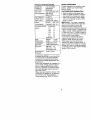
PRODUCT
REPAIR
SPECIFICATIONS
GASOLINE
CAPACITY
AND TYPE:
1.25 GALLONS
UNLEADED
REGULAR
31LTYPE
_,PI-SF/SG/SH):
SAE 30(ABOVE 32°F)
SAE 5W-30
(Below 32°F)
3.0 PINTS
31L CAPACITY:
SPARK PLUG:
GAP: .030")
VALVE
CHAMPION
RJ19LM OR J19LM
CLEARANCE:
GROUND SPEED
EXHAUST:.009"-.011"
INTAKE:
.005"-.007"
FORWARD:
1ST
1.1
2ND
2.2
3RD
3.4
4TH
4.3
5TH
REVERSE:
5.5
1.7
TIRE
PRESSURE:
FRONT:
REAR:
14 PSI
12 PSI
CHARGING
SYSTEM:
3 AMPS BATTERY
5 AMPS HEADLIGHTS
BATTERY:
AMP/HR;
25
MIN. CCA: 190
CASE SIZE:UIR
BLADE BOLT
tORQUE:
27-35 FT. LBS
(MPH):
AGREEMENT
A Repair Agreement is available on this
product. Contact your nearest Sears
store for details,
CUSTOMER
RESPONSIBILITIES
• Read and observe the safety rules.
• Follow a regular schedule in maintaining, caring for and using your tractor.
• Follow the instructions under "Maintenance" and "Storage" sections of this
owner's manual.
_I, WARNING: This tractor is equipped
with an internal combustion engine and
should not be used on or near any
unimproved forest-covered, brushcovered or grass-covered land unless the
engine's exhaust system is equipped with
a spark arrester meeting applicable local
or state laws (if any). If a spark arrester is
used, it should be maintained in effective
working order by the operator.
In the state of California the above is
required by law (Section 4442 of the
California Public Resources Code).
Other states may have similar laws.
Federal laws apply on federal lands. A
spark arrester for the muffler is available
through your nearest authorized service
center/department
(See REPAIR PARTS
section of this manual).
CONGRATULATIONS
on your purchase
of a new tractor. It has been designed,
engineered and manufactured to give
you the best possible dependability and
performance.
Should you experience any problem you
cannot easily remedy, please contact a
Sears or other qualified service center.
We have competent, well-trained technicians and the proper tools to service or
repair this tractor.
Please read and retain this manual. The
instructions will enable you to assemble
and maintain your tractor properly.
Always observe the "SAFETY RULES".
6
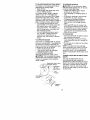
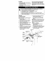
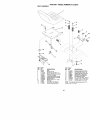
Steering
Wheel
Steering
Sleeve
Steering
Wheel
Adapter
(1) Large Flat
Washer
t
Extension
Shaft
teering
(1) Hex Bolt
3/8-16 x 1
Steering
Wheel
Insert
(1) Lock
washer
_
3/8
Locknut
(1) Hex Bolt
5/16-18 x 1-1/4
Seat
\
\
(1) Washer
17/32 x 1-3/16 x 12 Gauge
(1) Knob
Keys
Video
Cassette
(2) Keys
7
Slope
Sheet
Your new tractor has been assembled at the factory with exception of those parts left
unassembled for shipping purposes. To ensure safe and proper operation of your
tractor all parts and hardware you assemble must be tightened securely, Use the
correct tools as necessary to insure proper tightness, Review the video cassette before
you begin.
TOOLS REQUIRED FOR
6. Assemble large flat washer, 3/8 lock
ASSEMBLY
washer, 3/8 hex bolt and tighten
securely,
A socket wrench set will make assembly
7. Snap steering wheel insert into center
easier. Standard wrench sizes you need
of steering wheel.
are listed below.
8. Remove protective materials from
(1) 9/16" wrench
(1) Pliers
tractor hood and grill.
(2) 1/2" wrench
(1) Utility knife
IMPORTANT:
Check for and remove any
(1) Tire pressure
staples in skid that may puncture tires
gauge
where lractor is to roll off skid.
When right or left hand is mentioned in
this manual, it means, from your point of
view, when you are in the operating
position (seated behind the steering
wheel).
TO REMOVETRACTOR
FROM
CARTON
UNPACK CARTON
1. Remove all accessible loose parts
and parts cartons from carton.
2. Cut, from top to bottom, along lines
on all four corners of carton, and lay
panels flat.
3. Check for any additional loose parts
or cartons and remove.
BEFORE REMOVING TRACTOR
FROM SKID
ATTACH STEERING WHEEL
ASSEMBLE EXTENSION SHAFT AND
BOOT
1. Slide extension shaft onto lower
steering shaft. Align mounting holes
in extension and lower shafts and
install 5/16 hex bolt and Iocknut,
Tighten securely.
2. Place tabs of steering boot over tab
slots in dash and push down to
secure.
HOWTO SET UPYOURTRACTOR
CHECK BATTERY
1. Lift seat pan to raised position and
open battery box door.
NOTE: If this battery is put into service
after month and year indicated on label
(label located between terminals) charge
battery for minimum of one hour at 6-10
amps. (See "BATTERY" in Maintenance
section of this manual for charging
instructions).
INSTALL STEERING WHEEL
3. Position front wheels of the tractor so
they are pointing straight forward.
4. Remove steering wheel adapter from
steering wheel and slide adapter
onto steering shaft extension.
5. Position steering wheel so cross bars
are horizontal (left to right) and slide
inside boot and onto adapter.
8
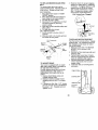
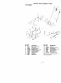
Battery Box
Laber
INSTALL SEAT
Adjust seat before tightening adjustment
knob.
1. Remove adjustment knob and flat
washer securing seat to cardboard
packing and set aside for assembly of
seat to tractor.
2. Pivot seat upward and remove from
the cardboard packing. Remove the
cardboard packing and discard.
3. Place seat on seat pan and assemble
shoulder bolt. Tighten shoulder bolt
securely.
4. Assemble adjustment knob and flat
washer loosely. Do not tighten.
5. Lower seat into operating position and
sit on seat.
6. Slide seat until a comfortable position
is reached which allows you to press
clutch/brake pedal all the way down.
7. Get off seat without moving its
adjusted position.
8. Raise seat and tighten adiustment
knob securely.
Seat
Seat Pan
Shoulder
Bolt
TO ROLLTRACTOR
OFF SKID (See
Operation section for location and
function
of controls)
1. Press lift lever plunger and raise
attachment lift lever to its highest
position.
2. Release parking brake by depressing
clutch/brake pedal.
3. Place gearshift lever in neutral (N)
position.
4, Roll tractor forward off skid.
5. Remove banding holding deflector
shield up against tractor.
TO DRIMETRACTOR
OFF SKID (See
Operation
section for location
and
function
of controls)
_WARNING:
Before starting, read,
understand and follow all instructions in
the Operation section of this manual Be
sure tractor is in a well-ventilated area. Be
sure the area in front of tractor is clear of
other people and objects.
1. Be sure all the above assembly steps
have been completed.
2. Check engine oil level and fill fuel tank
with gasoline.
3. Sit on seat in operating position,
depress clutch/brake pedal and set
the parking brake.
4. Place gear shift lever in neutral (N)
position.
5. Press lift lever plunger and raise
attachment lift lever to its highest
position.
6. Start the engine. After engine has
started, move throttle control to idle
position.
7. Depress clutch/brake pedar into full
"BRAKE" position and hold. Move
gearshift lever to 1st gear.
8. Slowly release clutch/brake pedal and
slowly drive tractor off skid.
9. Apply brake to stop tractor, set parking
brake and place gearshift lever in
neutral position.
10.Turn ignition key to "OFF" position.
Continue with the instructions that follow.
Flat Washer
Adjustment
Knob
NOTE: You may now roll or drive your
tractor off the skid. Follow the appropriate
instruction below to remove the tractor
from the skid.
9
CHECKTIRE
PRESSURE
The tires on your tractor were overinflated
at the factory for shipping purposes.
Correct tire pressure is impodant for best
culling performance.
• Reduce tire pressure to PSI shown in
"PRODUCT SPECIFICATIONS" section
of this manual.
CHECK
DECK
LEVELNESS
For best cutting results, mower housing
should be properly leveled. See "TO
LEVEL MOWER HOUSING" in the
Service and Adjustments section of this
manual.
CHECK FOR PROPER
ALL BELTS
POSITION
OF
See the figures that are shown for
replacing motion and mower blade drive
belts in the Service and Adjustments
section of this manual. Verify that the
belts are routed correctly.
CHECK BRAKE SYSTEM
After you learn how to operate your
tractor, check to see that the brake is
properly adjusted. See "TO ADJUST
BRAKE" in the Service and Adjustments
section of this manual.
",/'CHECKLIST
Before you operate and enjoy your new
tractor, we wish to assure that you receive
the best performance and satisfaction
from this Quality Product.
Please review the following checklist:
,/" All assembly instructions have been
completed.
.4' No remaining loose parts in carton.
y Battery is properly prepared and
charged.
(Minimum 1 hour at 6 amps),
y Seat is adjusted comfortably and
lightened securely.
yAll tires are properly inflated. (For
shipping purposes, the tires were
overinflated at the factory).
y Be sure mower deck is properly leveled
side-tooside/front-to-rear
for best cutting
results. (Tires must be properly inflated
for leveling).
yCheck mower and drive belts. Be sure
they are routed properly around pulleys
and inside all belt keepers.
y/Check wiring. See that all connections
are still secure and wires are properly
clamped.
While learning how to use your tractor.
pay extra attention to the following
important items:
4" Engine oil is at proper level.
,/Fuel tank is tilled with fresh, clean,
regular unleaded gasoline.
y/Become familiar with all controls - their
location and function. Operate them
before you start the engine.
_" Be sure brake system is in safe
operating condition.
10
These symbols may appear on your tractor or in literature supplied with the product.
Learn and understand their meaning.
BATTERY
CAUTION
OR
REVERSE
FORWARD
FAST
SLOW
WARNfNG
ENGINE
ON
FUEL
ENGINE
OFF
CHOKE
OIL PRESSURE
MOWER
HEIGHT
R N
ATTACHMENT
CLUTCH
ENGAGED
REVERSE
LIGHTS
ON
PARKING
DRAKE
LOCKED
H
NEUTRAL
OVER TEMP
LIGHT
AREA
!
MOWER
UNLOCKED
LIFT
L
HIGH
KEEP
t
LOW
CLEAR
PARKING
SLOPE
RRAKE
HAZARDS
ATTACHMENT
IGNITION
DANGER,
CLUTCH
KEEP
HANDS
AND
(SEE
DISENGAGED
FEET
SAFETY
RULES
SECTION)
FREE WHEEL
(Automatic Models only)
AWAY
il
KNOWYOURTRACTOR
READ THIS OWNER'S
YOUR TRACTOR
MANUAL AND SAFETY RULES BEFORE OPERATING
Compare the illustrations with your tractor to familiarize yourself with the locations of
various controls and adjustments. Save this manual for future reference.
Attachment
Lever
Clutch
Ignition Switch
ht Switch
Lever
Plunger
Throttle/Choke
ent
Lift Lever
Clutch/
Height
Adjustment
' Indicator
g Brake Lever
1
Gearshift Lever
Our tractors conform to the safety standards of the American National Standards
Institute.
ATTACHMENT CLUTCH LEVER - Used
to engage the mower blades, or other
attachments mounted to your tractor.
ATTACHMENT LIFT LEVER - Used to
raise, lower, and adjust the mower deck
or other attachments mounted to your
tractor.
CLUTCH/BRAKE
PEDAL - Used for
declutching and braking the tractor and
starting the engine.
GEARSHIFT LEVER - Selects the speed
and direction of tractor,
IGNITION SWITCH - Used for starting and
stopping the engine.
LIFT LEVER PLUNGER - Used to release
attachment lift lever when changing its
position.
LIGHT SWITCH - Turns the headlights on
and off.
PARKING BRAKE LEVER - Locks clutch/
brake pedal into the brake position.
THROTTLE/CHOKE
CONTROL - Used
for starting and controlling engine speed.
12
r
The operation of any tractor can result in foreign objects thrown into
the eyes, which can result in severe eye damage. Always wear safety
glasses or eye shields while operating your tractor or performing any
adjustments or repairs. We recommend a wide vision safety mask
over spectacles or standard safety glasses.
HOWTO USEYOURTRACTOR
TO SET PARKING BRAKE
Your tractor is equipped with an operator
presence sensing switch. When engine
is running, any attempt by the operator to
leave the seat without first setting the
parking brake will shut off the engine.
1. Depress clutch/brake pedal into full
"BRAKE" position and hold.
2. Place parking brake lever in "ENGAGED" position and release
pressure from clutch/brake pedal.
Pedal should remain in "BRAKE"
position. Make sure parking brake will
hold tractor secure.
AttachmentClutch Lever
_Engaged"Position
Throttle/Choke
Control
\
Clutch/
Brake
Pedal
Position
Parking
Brake
"Engaged"
Position
Gearshift
Lever
"Brake ....
Position
STOPPING
Disengaged"
Position
MOWER BLADES • To stop mower blades,move attachmenl clutch lever to "DISENGAGED"
position.
GROUND DRIVE • To stop ground drive, depress clutch/
brake pedal into full "BRAKE" position.
• Move gearshift lever to neutral (N)
position.
ENGINE • Move throttle control to slow position.
NOTE: Failure to move throttle control to
slow position and allowing engine to idle
before stopping may cause engine to
"backfire".
• Turn ignition key to "OFF" position and
remove key. Always remove key when
leaving tractor to prevent unauthorized
use.
• Never use choke to stop engine.
IMPORTANT: Leaving the ignition switch
in any position other than "OFF" will
cause the battery to be discharged,
(dead).
NOTE: Under certain conditions when
tractor is standing idle with the engine
running, hot engine exhaust gases may
cause "browning" of grass. To eliminate
this possibility, always stop engine when
stopping tractor on grass areas.
_CAUTION:
Always stop tractor
completely, as described above, before
leaving the operator's position; to empty
grass catcher, etc.
TO USE THROTTLE
CONTROL
Always operate engine at full throttle.
• Operating engine at less than full
throttle reduces the battery charging
rate.
• Full throttle offers the best bagging and
mower performance.
TO MOVE FORWARD AND BACKWARD
The direction and speed of movement is
contro,ed by the gearshift lever.
1. Start tractor with clutch/brake pedal
depressed and gearshift lever in
neutral (N) position.
2. Move gearshift lever to desired
position.
3. Slowly release clutch/brake pedal to
start movement.
IMPORTANT: Bring tractor to a complete
stop before shifting or changing gears.
Failure to do so will shorten the useful life
of your transaxle.
:13
TO ADJUST MOWER CUTTING HEIGHT
TO OPERATE ON HILLS
The position of the attachment _ift lever
determines the cutting height.
• Grasp lifl lever.
• Press plunger with thumb and move
lever to desired position.
The cutting height range is approximately 1-1/2 to 4". The heights are
measured from the ground to the blade
lip with the engine not running. These
heights are approximate and may vary
depending upon soil conditions, height of
grass and types of grass being mowed.
• The average lawn should be cut to
approximately 2-1/2 inches during the
cool season and to over 3 inches
during hot months. For healthier and
better looking lawns, mow often and
after moderate growth.
• For best cutting performance, grass
over 6 inches in height should be
mowed twice. Make the first cut
relatively high; the second to desired
height.
_I,CAUTION: Do not drive up or down
hills with slopes greater than 15° and
not drive across any slope.
• Choose the slowest speed before
starting up or down hills.
• Avoid stopping or changing speed o=
hills.
• If slowing is necessary, move throttle
control lever to slower position.
• If stopping is absolutely necessary,
push clutch/brake pedal quickly to
brake position and engage parking
brake.
• Move gearshift lever to 1st gear. Be
sure you have allowed room for tract(
to roll slightly as you restart movemer
• To restad movement, slowly release
parking brake and clutch/brake pedal
• Make all turns slowly.
TO TRANSPORT
TO OPERATE MOWER
Your tractor is equipped with an operator
presence sensing switch. Any attempt by
the operator to leave the seat with the
engine running and the attachmenl clutch
engaged will shut off lhe engine.
1, Select desired height of cut.
2, Start mower blades by engaging
attachment clutch control.
TO STOP MOWER BLADESdisengage attachment clutch control.
_kCAUTION:
Do not operate the mower
without either the entire grass catcher, on
mowers so equipped, or the deflector
shield in place,
Attachment Clutch Lever
"Engaged" Position
Lilt Lever
• Raise attachment lift to highest positi,
with attachment lift control.
• When pushing or towing your tractor,
be sure gearshift lever is in neutral (I_
position.
• Do not push or tow tractor at more th_
five (5) MPH,
NOTE: To protect hood from damage
when transporting your tractor on a truc
or a trailer, be sure hood is closed and
secured to tractor. Use an appropriate
means of tying hood to tractor (rope, co
etc.).
TOWING CARTS AND OTHER ATTAC
MENTS
Tow only the attachments that are
recommended by and comply with
specifications o1 the manufacturer of yc
tractor. Use common sense when towin(
Too heavy of a load, while on a slope, i,,
dangerous. Tires can lose traction with
the groLmd and cause you to lose contr,
o1 your tractor.
_High
Position
Low
Position
Position
- .
Shield
14
BEFORE STARTINGTHE
ENGINE
CHECK ENGINE OIL LEVEL
TO START
ENGINE
When starting the engine for the first timeor if
the engine has run outof fuel, it wilttake extra
crankingtime to move fuel from the tank to
the engine,
1. Sit on seat in operating position,
depress clutch/brake pedal and set
parking brake.
2. Place gear shift lever in neutral (N)
position.
3. Move attachment clutch to "DISENGAGED" position.
4. Move throttle control to choke position.
NOTE: Before starting,read the warm and
cold startingprocedures below.
5. Insert key into ignition and turn key
clockwise to "START" position and
release key as soon as engine starts.
Do not run starter continuously for
more than fifteen seconds per minute.
If the engine does not start after
several attempts, move throttle control
to fast position, wait a few minutes and
try again. If engine still does not start,
move the throttle control back to the
choke position and retry.
The engine in your tractor has been
shipped, from the factory, already filled
with summer weight oil.
1. Check engine oil with tractor on level
ground.
2. Remove oil fill cap/dipstick and wipe
clean, reinsert the dipstick and screw
cap tight, wait for a few seconds,
remove and read oil level. If necessary, add oil until "FULL" mark on
dipstick is reached. Do not overfill.
• For cord weather operation you should
change oil for easier starting (See "OIL
VISCOSITY CHART" in the Maintenance section of this manuar).
• To change engine oil, see the Maintenance section in this manual.
ADD GASOLINE
• Fill fuel tank. Use fresh, clean, regular
unleaded gasoline with a minimum of
87 octane. (Use of leaded gasoline
will increase carbon and read oxide
deposits and reduce valve life). Do not
mix oil with gasoline. Purchase fuel in
quantities that can be used within 30
days to assure fuel freshness.
IMPORTANT: When operating in
temperatures below 32°F(0°C), use fresh,
clean winter grade gasoline to help
insure good cold weather starting.
,_WARNING:
Experience indicates that
alcohol blended fuels (called gasohor or
using ethanol or methanol) can attract
moisture which leads to separation and
formation of acids during storage. Acidic
gas can damage the fuel system of an
engine while in storage. To avoid engine
problems, the fuel system should be
emptied before storage of 30 days or
longer. Drain the gas tank, start the
engine and let it run until the fuel lines
and carburetor are empty. Use fresh fuel
next season. See Storage rnstructions for
additional information.
Never use engine
or carburetor cleaner products in the fuel
tank or permanent damage may occur.
_,CAUTION:
Fill to bottom of gas tank
filler neck. Do not overfill. Wipe off any
spilled oil or fuel. Do not store, spill or
use gasoline near an open flame.
WARM WEATHER STARTING (50° F and
above)
6. When engine starts, move the throttle
control to the fast position.
• The attachments and ground drive can
now be used. If the engine does not
accept the load, restart the engine and
allow it to warm up for one minute
using the choke as described above.
COLD WEATHER STARTING ( 50° F and
below)
6. When engine starts, allow engine to
run with the throttle control in the
choke position until the engine runs
roughly, then move throttle control to
fast position. This may require an
engine warm-up period from several
seconds to several minutes, depending on the temperature.
• The attachments can also be used
during the engine warm-up period.
NOTE: If at a high altitude(above 3000 feet)
or in cold temperatures (below 32 F) the
carburetor fuel mixturemay need to be
adjusted for best engine performance. See
"TO ADJUST CARBURETOR" in the Service
and Adjustments section of this manual.
i5
MOWlNGTIPS
• Tire chains cannot be used when the
mower housing is attached to tractor.
• Mower should be properly leveled for
best mowing performance. See "TO
LEVEL MOWER HOUSING" in the
Service and Adjustments section of this
manual.
• The left hand side of mower should be
used for trimming.
• Drive so that clippings are discharged
onto the area that has been cut. Have
the cut area to the right of the tractor.
This will result in a more even distribution of clippings and more uniform
cutting.
• When mowing large areas, start by
turning to the right so that clippings wilt
discharge away from shrubs, fences,
driveways, etc. After one or two
rounds, mow in the opposite direction
making left hand turns until finished.
• If grass is extremely tall, it should be
mowed twice to reduce load and
possible fire hazard from dried clippings. Make first cut relatively high; the
second to the desired height.
• Do not mow grass when it is wet. Wet
grass will plug mower and leave
undesirable clumps. Allow grass to dry
before mowing.
• Always operate engine at full throtUe
when mowing to assure better mowing
performance and proper discharge of
material. Regulate ground speed by
selecting a low enough gear to give the
mower cutting performance as well as
the quality of cut desired.
• When operating attachments, select a
ground speed that will suit the terrain
and give best performance of the
attachment being used.
I
16
2 • $_,vice _or_ c_len whe_ ope_tr,g
in diay o_duSly cor,dd_ns
6 NOl r,_,_r ed _ equ,_p,_f with m_r4enance Ir_,_bat_e_
7 • T_ghle,_ t_c_t a_l_ p;vo_bOl__o 35 II t,s maximum
Oo no1 overt_gaten
• _er,_¢e t_la_,_Sraore o_e_ wren r_,_wing in sandy sol_
GENERAL
RECOMMENDATIONS
The warranty on this tractor does not
cover items that have been subjected to
operator abuse or negligence. To receive
full value from the warranty, operator must
maintain tractor as instructed in this
manual.
Some adjustments will need to be made
periodically to properly maintain your
tractor.
All adjustments in the Service and
Adjustments section of this manual
shourd be checked at least once each
season.
• Once a year you should replace the
spark plug, clean or replace air filter,
and check blades and belts for wear. A
new spark plug and clean air filter
assure proper air-fuel mixture and help
your engine run better and last longer.
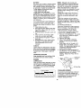
LUBRICATION CHART
d) Spindle _f_'_
Zerk___ :t,I,,
r---
_.____
__
=_
_J)Spindle
Zerk
q_Front Wheel _4
_-,
(#Froilt Wheel
Bearing
_
..... _ ! ! Bearing Zerk
Zerk
S,
_ - _.__.;
- - _ll_
(OSAE OR 10W30 MOTOR OIL
_)REFER TO MAINTENANCE "ENGINE"
SECTION
BEFORE EACH USE
IMPORTANT: Do not oil or grease the
1. Check engine oil level.
pivot points which have special nylon
2. Check brake operation,
bearings. Viscous lubricants will attract
3. Check tire pressure•
dust and dirt that will shorten the life of
4. Check operator presence and
the self-lubricating bearings. If you feel
interlock systems for proper operation.
they must be lubricated, use only a dry,
5. Check for loose fasteners.
powdered graphite type lubricant
17sparingly.
TRACTOR
Always observe safety rules when
performing any maintenance.
BRAKE OPERATION
If tractor requires more than six (6) feet
stopping distance at high speed in
highest gear, then brake must be adjusted. (See "TO ADJUST BRAKE" in the
Service and Adjustments section of this
manual).
TIRES
• Maintain proper air pressure in all tires
(See "PRODUCT SPECIFICATIONS"
section of this manual).
• Keep tires free of gasoline, oil, or insect
control chemicals which can harm
rubber.
• Avoid stumps, stones, deep ruts, sharp
objects and other hazards that may
cause tire damage.
NOTE: To seal tire punctures and prevent
flat tires due to slow leaks, tire sealant
may be purchased from your local parts
dealer. Tire sealant also prevents tire dry
rot and corrosion.
OPERATOR PRESENCE SYSTEM
Be sure operator presence and interlock
systems are working properly, If your
tractor does not function as described,
repair the problem immediately.
• The engine should not start unless the
clutch/brake pedal is fully depressed
and attachement clutch control is in the
disengaged position.
• When the engine is running, any
attempt by the operator to leave the
seat without first setting the parking
brake should shut off the engine.
• When the engine is running and the
attachment clutch is engaged, any
attempt by the operator to leave the
seat should shut off the engine.
• The attachment clutch should never
operate unless the operator is in the
seat.
BLADE CARE
For best results mower blades must be
kept sharp. Replace bent or damaged
blades.
IMPORTANT: To ensure proper assembly,
center hole in blade must align with star
on mandrel assembly.
4. Reassemble hex bolt, lock washer
and flat washer in exact order as
shown.
5. Tighten bolt securely (27-35 Ft. Lbs.
torque).
IMPORTANT:
Blade bolt is grade 8 heat
treated.
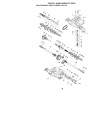
Trailing Edge Up
_,, Blade
Leek Washer
Mandrel Assembly
Center *_i "_
\'-v_--,
;
XS
ar
_";_---HexBolt (Gradei _ :"-_
*A Grade 8 heat treated bolt can be identified
by six lines on the belt head.
TO SHARPEN
BLADE
NOTE: We do not recommend sharpening blade - but if you do, be sure the
blade is balanced.
Care should be taken to keep the blade
balanced. An unbalanced blade will
cause excessive vibration and eventual
damage to mower and engine.
• The blade can be sharpened with a file
or on a grinding wheel. Do not attempt
to sharpen while on the mower.
• To check blade balance, you will need
a 5/8" diameter steel bolt, pin, or a cone
balancer. (When using a cone balancer, follow the instructions supplied
with balancer.)
NOTE: Do not use a nail for balancing
blade. The lobes of the center hole may
appear to be centered, but are not.
• Slide blade on to an unthreaded
portion of the steel boll or pin and hold
the bolt or pin parallel with the ground.
If blade is balanced, it should remain in
a horizontal position. If either end of
the blade moves downward, sharpen
the heavy end until the blade is
balanced.
BLADE REMOVAL
1. Raise mower to highest position to
allow access to blades.
2. Remove hex bolt, lock washer and flat
washer securing blade.
3. Install new or resharpened blade with
trailing edge up towards deck as
shown.
5/8" Bolt or Pin
"
Center Hole
18
Blade
BATTERY
Your tractor has a battery charging system
which is sufficient for normal use. However, periodic charging of the battery with
an automotive charger will extend its life.
• Keep battery and terminals dean.
• Keep battery bolts tight.
• Keep small vent holes open.
• Recharge at 6-10 amperes for 1 hour.
NOTE: The original equipment battery on
your tractor is maintenance free. Do not
attempt to open or remove caps or covers.
Adding or checking level of electrolyte is
not necessary.
TO CLEAN BATTERY AND TERMINALS
Corrosion and dirt on the battery and
terminals can cause the battery to "leak"
power.
1. Open battery box door.
2. Disconnect BLACK battery cable first
then RED battery cable and remove
battery from tractor.
3. Rinse the battery with plain water and
dry.
4. Clean terminals and battery cable
ends with wire brush until bright.
5. Coat terminals with grease or petroleum jelly.
6. Reinstall battery (See "REPLACING
BATTERY" in the SERVICE AND
ADJUSTMENTS section of this
manual).
V-BELTS
Check V-belts for deterioration and wear
after t00 hours of operation and replace
if necessary. The belts are not adjustable.
Replace belts if they begin to slip from
wear.
TRANSAXLE
NOTE: Although multi-viscosity oils
(5W30, 10W30 etc.) improve starting in
cold weather, these multi-viscosity oils
will result in increased oil consumption
when used above 32°E Check your
engine oil level more frequently to avoid
possible engine damage from running
low on oil.
Change the oil after every 25 hours of
operation or at least once a year if the
tractor is not used for 25 hours in one
year.
Check the crankcase oil level before
starting the engine and after each eight
(8) hours of operation. Tighten oil fill cap/
dipstick securely each time you check the
oil level.
TO CHANGE ENGINE OIL
Determine temperature range expected
before oil change. All oil must meet API
service classification SF, SG or SH.
• Be sure tractor is on level surface.
• Oil will drain more freely when warm.
• Catch oil in a suitable container.
1. Remove oil fill cap/dipstick. Be careful
not to allow dirt to enter the engine
when changing oil.
2. Remove drain plug.
3. After oil has drained completely,
replace oil drain plug and tighten
securely.
4. Refill engine with oil through oil fill
dipstick tube. Pour slowly. Do not
overfill. For approximate capacity see
"PRODUCT SPECIFICATIONS"
section of this manual.
5. Use gauge on oil fill cap/dipstick for
checking level. Be sure dipstick cap is
tightened securely for accurate
reading. Keep oil at "FULL" line on
dipstick.
COOLING
Keep transaxle free from build-up of dirt
and chaff which can restrict cooling.
_'F_
ENGINE
LUBRICATION
Only use high quality detergent oil rated
with API service classification SF, SG, or
SH. Select the oil's SAE viscosity grade
according to your expected operating
temperature.
SAE VISCOSITY
c
t_'-
;_
.'o
TE_ANGE
_o
o
.io
o
......
AN_iPATEO
_0
_o ¸
_
_
_
"_ C_l. C_-N 6E
lea
NE;,:I
O
_
_
Oil Fill Cap/
Dipstick
il Drain Plug
CLEAN AIR SCREEN
Air screen must be kept free of dirt and
chaff to prevent engine damage from
overheating. Clean with a wire brush or
compressed air to remove dirt and
stubborn dried gum fibers.
GRADES
io
B_FO_
/€=:;=::_:::::::_
i
i9
ENGINE COOLING FINS
Remove any dust, dirt or oil from engine
cooling fins to prevent engine damage
from overheating.
1. Remove screws from blower housing
and lift housing and dipstick tube
assembly off engine.
2. Cover oil till opening to prevent entry
of dirt.
3. Use compressed air or stiff bristle
brush to thoroughly clean engine
cooling fins.
4. To reassemble, reverse above
procedure.
Scre _B(_wer
Housing
3. Clean cartridge by tapping gently on
flat surface.
NOTE: If very dirty or damaged, replace
cartridge.
4. Reinstall cartridge, nut, precleaner,
cover and secure with knob(s).
IMPORTANT: Petroleum solvents,such as
kerosene,are not to be used to clean the
cartridge. They may cause deterioration of the
cartridge. Do not oilcartridge. Do not use
pressurizedair to clean or dry cartridge.
Cover Knob
Screws
DipstickTube .==_m.,=
Assemb,y
_Spark
L I
EngineCooling Fins_
MUFFLER
Plug
AIR FILTER
Your engine will not run properly using a
dirty air filter. Clean the foam pre-cleaner
after every 25 hours of operation or every
season. Service paper cartridge every
100 hours of operation or every season,
whichever occurs first.
Service air cleaner more often under
dusty conditions.
1. Remove knob(s) and cover.
TO SERVICE PRE-CLEANER
2.
3.
4.
5.
Slide foam pre-cleaner off cartridge.
Wash it in liquid detergent and water.
Squeeze it dry in a clean cloth.
Saturate it in engine oil. Wrap it in
clean, absorbent cloth and squeeze to
remove excess oil
NOTE: If very dirty or damaged, replace
pre-cleaner.
6. Reinstall pre-cleaner over cartridge.
7. Reinstall cover and secure with
knob(s).
TO SERVICE CARTRIDGE
Inspect and replace corroded muffler and
spark arrester (if equipped) as it could
create a fire hazard and/or damage.
SPARK PLUGS
Replace spark plugs at the beginning of
each mowing season or after every 100
hours of operation, whichever occurs first.
Spark plug type and gap setting are
shown in "PRODUCT SPECIFICATIONS"
section of this manual.
IN-LINE FUEL FILTER
The fuel filter should be replaced once
each season. If fuel filter becomes
clogged, obstructing fuel flow to carburetor, replacement is required.
1. With engine cool, remove filter and
plug fuel line sections.
2. Place new fuel filter in position in fuel
line with arrow pointing towards
carburetor.
3. Be sure there are no fuel line leaks
and clamps are properly positioned.
4. Immediately wipe up any spilled
gasoline.
Clamp _
1. Remove cartridge nut.
2. Carefully remove cartridge to prevent
debris from entering carburetor.
Clean base carefully to prevent debris
from entering carburetor.
Fuel Filte r---""'_
2O
CLEANING
• Clean engine, battery, seat, finish, etc.
of all foreign matter.
• Keep finished surfaces and wheels free
of all gasoline, oil, etc.
• Protect painted surfaces with automotive type wax.
_
We do not recommend using a garden
hose to clean your tractor unless the
electrical system, muffler, air filter and
carburetor are covered to keep water out.
Water in engine can resuJt in a shortened
engine life.
CAUTION:
1. Depress clutch/brake
BEFORE PERFORMING
pedal fully and
ANY
setSERVICE
parking brake.
OR ADJUSTMENTS:
2. Place gearshift lever in neutral (N) position.
3. Place attachment clutch in "DISENGAGED" position.
4. Turn ignition key "OFF" and remove key.
5. Make sure the blades and all moving parts have completely stopped.
6. Disconnect spark plug wire from spark plug and place wire where it cannot
come in contact with plug.
TRACTOR
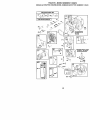
8. Disconnect front links from deck by
removing retainer springs.
TO REMOVE MOWER
9. Raise lift lever to raise suspension
Mower will be easier to remove from the
arms. Slide mower out from under
right side of tractor.
tractor.
1. Place attachment clutch in "DISENIMPORTANT: If an attachment other than
GAGED" position.
the mower deck is to be mounted on the
2. Move attachment lift lever forward to
tractor, remove the front links and hook
lower mower to its lowest position.
the clutch spring Into square hole in
3. Roll belt off engine pulley.
frame.
4. Remove small retainer spring, and lift
TO INSTALL MOWER
clutch spring off pulley bolt.
1. Raise attachment lift lever to its
5. Remove large retainer spring, slide
highest position.
collar off and push housing guide out
2. Slide mower under tractor with
of bracket.
discharge guard to right side of tractor.
6. Disconnect anti-swaybar from chassis
3. Lower lift lever to its lowest position.
bracket by removing retainer spring.
4. Install mower in reverse order of
7. Disconnect suspension arms from
removal instructions.
rear deck brackets by removing
retainer springs.
ArmsSuspensi°n. _, ,::,;:
:: ,
Small Retainer
" " :..-.-_----Square
Hole
Clutch
Retainer
Link
Retainer Springs
(Both Sides)
Anti-Sway
Bar _
Guide
Large Retainer
Spring
TO LEVEL MOWER HOUSING
Adjust the mower while tractor is parked
on level ground or driveway. Make sure
tires are properly inflated (See "PRODUCT SPECIFICATIONS" section of this
manual). If tires are over or
underinflated, you will not properly adjust
your mower.
SIDE-TO-SIDE ADJUSTMENT
• Raise mower to its highest position.
• At the midpoint of both sides of mower,
measure height from bottom edge of
mower to ground. Distance "A" on
both sides of mower should be the
same or within 1/4" of each other.
• If adjustment is necessary, make
adjustment on one side of mower only.
• To raise one side of mower, tighten lift
link adjustment nut on that side.
• To lower one side of mower, loosen lift
link adjustment nut on that side.
NOTE: Each full turn of adjustment nut
will change mower height about 1/8".
• Recheck measurements after adjusting.
Bottom edge of
mower to ground
Check adjustment on right side of tractor.
Measure distance "D" directly in front and
behind the mandrel at bottom edge of
mower housing as shown.
• Before making any necessary adjustments, check that both front links are
equal in length. Both links should be
approximately 10-3/8".
• If links are not equal in length, adjust
one link to same length as other link.
• To lower front of mower loosen nut "E"
on both front links an equal number of
turns.
• When distance "D" is 1/8" to 1/2" lower
at front than rear, tighten nuts "F"
against trunnion on both front links.
• To raise front of mower, loosen nut "F"
from trunnion on both front links.
Tighten nut "E" on both front links an
equal number of turns.
• When distance "D" is 1/8" to 1/2" lower
at front than rear, tighten nut "F" against
trunnion on both front links.
• Recheck side-to-side adjustment.
Bottom edge of
mower to ground
Both Front Links Should be Equal in Length
Q
Suspension Arm
Nut
Trunnion-
FRONT-TO-BACK ADJUSTMENT
IMPORTANT: Deck must be level side-to
side. If the following front-to-back adjustment is necessary, be sure to adjust both
front links equally so mower will stay level
side-to-side.
To obtain the best cutting results, the
mower housing should be adjusted so
that the front is approximately 1/8" to 1/2"
lower than the rear when the mower is in
its highest position.
Front Links
22
TO REPLACE MOWER BLADE DRIVE
BELT
The mower blade drive belt may be
replaced without tools. Park the tractor on
level surface. Engage parking brake,
BELT REMOVAL 1. Place attachment clutch in "DISENGAGED" position.
2. Move attachment lift lever forward to
lower mower to its lowest position.
3. Roll belt off engine pulley.
4. Disconnect R.H. suspension arm from
rear deck bracket by removing
retainer spring.
5. Work belt off both mandrel pulleys and
idler pulleys.
6. Pull belt away from mower.
BELT INSTALLATION 7. Instalr new belt in reverse order of
removal.
8. Make sure belt is in all pulley grooves
and inside all belt guides•
R.H. Suspension
Mandrel
._. ,'='_ Engine
Idler
.,Pulleys
Retaine_.
i
Mandrel
'+_ :
)
Pulley
TO ADJUST BRAKE
Your tractor is equipped with an adjustable brake system which is mounted on
the right side of the transaxle.
If tractor requires more than six (6) feet
stopping distance at high speed in
highest gear, then brake must be adjusted.
1. Depress clutch/brake pedal and
engage parking brake.
2. Measure distance between brake
operating arm and nut "A" on brake
rod.
3. If distance is other than 1-1/2", loosen
jam nut and turn nut "A" until distance
becomes 1-1/2". Retightenjam nut
against nut "A".
4. Road test tractor for proper stopping
distance as stated above. Readjust if
necessary. If stopping distance is still
greater than six (6) feet in highest
gear, further maintenance is necessary. Contact your nearest authorized service center/department.
With Parking Brake "Engaged"
Nut "A"
I \ ,JamNut
TO REPLACE MOTION DRIVE BELT
Park the tractor on level surface. Engage
parking brake. For assistance, there is a
belt installation guide decal on botlom
side of left footrest.
1. Remove mower (See "TO REMOVE
MOWER" in this section of this
manual.)
2. Remove belt from stationary idler and
clutching idler.
3. Pull belt slack toward rear of tractor.
Remove belt upwards from transaxle
pulley by deflecting belt keepers.
4. Pull belt toward front of tractor and
remove downwards from around
engine pulley.
5. install new belt by reversing above
procedure.
Clutching
Transaxle
23
TO ADJUST STEERING WHEEL ALIGNMENT
If steering wheel crossbars are not
horizontal (left to right) when wheels are
positioned straight forward, remove
steering wheel and reassemble per
instructions in the Assembly section of
this manual.
FRONT WHEEL TOE-IN/CAMBER
The front wheel toe-in and camber are
not adjustable on your tractor. If damage
has occurred to affect the front wheel toein or camber, contact your nearest
authorized service centeddepartment.
TO REMOVE WHEEL FOR REPAIRS
1. Block up axle securely.
2. Remove axle cover, retaining ring and
washers to aflow wheel removal (rear
wheel contains a square key - Do not
lose).
3. Repair tire and reassemble.
NOTE: On rear wheels only: align
grooves in rear wheel hub and axle.
insert square key.
4. Replace washers and snap retaining
ring securely in axle groove.
5. Replace axle cover.
NOTE: To seal tire punctures and prevent
fiat tires due to slow leaks, tire sealant
may be purchased from your local parts
dealer. Tire sealant also prevents tire dry
rot and corrosion.
Washers
Retaining_
TO START ENGINE WITH A WEAK
BATTERY
_CAUTION:
Lead-acid batteries
generate explosive gases. Keep sparks,
flame and smoking materials away from
batteries. Always wear eye protection
when around batteries.
If your battery is too weak to start the
engine, it should be recharged. (See
"BATTERY" in the MAINTENANCE
section of this manual).
If "jumper cables" are used for emergency
starting, follow this procedure:
IMPORTANT: Your tractor is equipped
with a 12 volt negative grounded system.
The other vehical must also be a 12 volt
negative grounded system. Do not use
your tractor battery to start other vehicles.
TO ATTACH JUMPER CABLES 1. Connect each end of the RED cable to
the POSITIVE (+) terminal of each
battery, taking care not to short
against chassis.
2. Connect one end of the BLACK cable
to the NEGATIVE (-) terminal of fully
charged battery.
3. Connect the other end of the BLACK
cable to good CHASSIS GROUND,
away from fuel tank and battery.
TO REMOVE CABLES, REVERSE
ORDER1. BLACK cable first from chassis and
then from the fully charged battery.
2. RED cable last from both batteries.
_'_L_.
Positive Terminal
Negative Terminal
OovorAx'e
it \ ll/ff 3A!
Square Key /
(Rear Wheel Only)
Terminal
Battery
Terminal
24
REPLACING BATTERY
,_CAUTION:
Do not short battery
terminals by allowing e wrench or any
other object to contact both terminals at
the same time. Before connecting battery,
remove metal bracelets, wristwatch
bands, rings, etc.
Positive terminal must be connected first
to prevent sparking from accidental
grounding.
1. Lift seat pan to raised position and
open battery box door.
2. Disconnect BLACK battery cable first
then RED battery cable and carefully
remove battery from tractor.
3. Install new battery with terminals in
same position as old battery.
4. First connect RED battery cable to
positive (+) terminal with hex boll and
keps nut as shown. Tighten securely.
5. Connect BLACK grounding cable to
negative (-) terminal with remaining
hex bolt and keps nut. Tighten
securely.
6. Close battery box door.
INTERLOCKS
AND RELAYS
Loose or damaged wiring may cause your
tractor to run poorly, stop running, or
prevent it from starting.
• Check wiring. See electrical wiring
diagram in the Repair Parts section.
TO REPLACE FUSE
Replace with 15 amp automotive-type
plug-in fuse. The fuse holder is located
behind the dash.
TO REMOVE HOOD AND GRILL ASSEMBLY
1. Raise hood.
2. Unsnap headlight wire connector.
3. Stand in front of tractor. Grasp hood a
sides, tilt toward engine and lift off of
tractor.
4. To replace, reverse above procedure,
,.___..__----,-Hood
Headlight Wire
Connector
/ '
,
Seat P
•
t,
Battery
Box
Positive
(Red) Cable
Negative
(Black) Cable
ENGINE
Maintenance, repair, or replacement of
the emission control devices and systems, which are being done at the
customers expense, may be performed
by any non-road engine repair establishment or individual. Warranty repairs must
be performed by an authorized engine
manufacturer's service outlet.
TO ADJUST THROTTLE CONTROL
CABLE
TO REPLACE HEADLIGHT BULB
1. Raise hood.
2. Pull bulb holder out of the hole in the
backside of the grill.
3. Replace bulb in holder and push bulb
holder securely back into the hole in
the backside of the grill.
4. Close hood.
The throttlecontrol has been preset at the
factoryand adjustmentshouldnot be
necessary. Check adjustmentas described
below before loosening cable. If adjustment
is necessary,proceed as follows:
1. With engine not running,move throttle
control lever from slow to choke position.
Slowly move lever from choke to fast
position.
25
2. Check that holes "A" in governor control
lever and hole in governor plate line-up.
If holes 'W' are not aligned, loosen clamp
screw and move throttle cable until holes
are aligned. Tighten clamp screw
securely.
Governor
Governor Control Lever
Control Plate
L
J
Holes
.
A,,
"
i
/_'
'_
i,_ ]'1 _1 \
_
I_.)_\
/
/
.;_i
Throttle
-= Clamp Screw
Cable
/
TO ADJUST CARBURETOR
NOTE: The carburetor on this engine is low
emission. It is equipped with an idle fuel
adjusting needle with a limiler cap, which
allows some adjustment within the limits
allowed by the cap. Do not attempt to remove
the limiter cap. The limiter cap cannot be
removed without breaking the adjusting
needle.
The carburetor has been preset at the fectory
and adjustment should not be necessary.
However, minor adjustment may be required
to compensate for differences in fuel,
temperature, altitude or load. If the carburetor
does need adjustment, proceed as follows:
In general, turning idle mixture valve in
(clockwise) decreases the supply of fuel to
the engine giving a leaner fueVair mixture.
Turning the idle mixture valve out (counterclockwise) increases the supply of fuel to the
engine giving a richerfueVair mixture.
IMPORTANT: Damage to the needle valve
and the seat in carburetor may result if screw
is turned in too tight.
PRELIMINARY SETFING 1. Air cleaner assembly must be assembled
to the carburetor when making carburetor
adjustments.
2. Be sure the throttle control cable is
adjusted propedy (see above).
FINAL SETFING 1. Start engine and allow to warm for five
minutes. Make final adjustments with
engine running and shift/motiee control
lever in neutral (N) position.
2. Move throttle control lever to slow
position. With finger, rotate and hold
throttle lever against idle speed screw.
Turn idle speed screw to attain 1750
RPM
3. While still holding throttle lever against
idle speed screw, turn idle mixture valve
full travel clockwise then counterclockwise until engine runs rough. Turn valve
to a point midway between those two
positions. Release throttle lever.
ACCELERATION TEST 4. Move throttle control lever from slow to
fast position• If engine hesitates or dies,
turn idle mixture valve out (counterclockwise) 1/8 turn. Repeat test and continue
to adjust, if necessary, until engine
accelerates smoothly.
High speed stop is factory adjusted. Do not
adjust - damage may result.
IMPORTANT: Never tamper with the engine
governor, which is factoryset for proper
engine speed. Overspeeding the engine
above the factory high speed setting can be
dangerous. If you think the engine-governed
high speed needs adjusting, contact your
nearest AUTHORIZED service center/
department, which has proper equipment
and experience to make any necessary
adjustments.
Idle Speed Screw
Lever
hrottle
_
{
26
IN(_::::_I
_'_L._
IdleMixture
Immediately prepare your tractor for
storage at the end of the season or if the
tractor will not be used for 30 days or
more.
,_CAUTION:
Never store the tractor with
gasoline in the tank inside a building
where fumes may reach an open flame or
spark. Allow the engine to cool before
storing in any enclosure.
TRACTOR
Remove mower from tractor for winter
storage. When mower is to be stored for
a period of time, clean it thoroughly,
remove all did, grease, leaves, etc. Store
in e clean, dry area.
1. Clean entire tractor (See "CLEANING"
in the Maintenance section of this
manual).
2. Inspect and replace belts, if necessary
(See belt repracement instructions in
the Service and Adjustments section
of this manual).
3. Lubricate as shown in the Maintenance section of this manual.
4. Be sure that all nuts, bolts and screws
are securely fastened. Inspect moving
pads for damage, breakage and wear.
Replace if necessary.
5. Touch up aM rusted or chipped paint
surfaces; sand lightly before painting.
BAI-rERY
• Fully charge the battery for storage.
• After a period of time in storage, battery
may require recharging.
• To help prevent corrosion and power
leakage during long periods of storage,
battery cables should be disconnected
and battery cleaned thoroughly (see
"TO CLEAN BATTERY AND TERMINALS" in the Maintenance section of
this manual).
• After cleaning, leave cables disconnected and place cables where they
cannot come in contact with battery
terminals.
• If battery is removed from tractor for
storage, do not store battery directly on
concrete or damp surfaces.
experianee indicates that alcohol
blended fuels (called gasohol or using
ethanol or methanol) can attract moisture
which leads to separation and formation
of acids during storage. Acidic gas can
damage the fuel system of and engine
while in storage.
1. Drain the fuel tank.
2. Start the engine and let it run until the
fuel lines and carburetor are empty.
• Never use engine or carburetor cleaner
products in the fuel tank or permanent
damage may occur.
• Use fresh fuel next season.
NOTE: Fuel stabilizer is an acceptabre
alternative in minimizing the formation of
fuel gum deposits during storage, Add
stabilizer to gasoline in fuel tank or
storage container. Always follow the mix
ratio found on stabilizer container. Run
engine at feast 10 minutes after adding
stabilizer to allow the stabilizer to reach
the carburetor. Do not drain the gas tank
and carburetor if using fuel stabilizer.
ENGINEOIL
Drain oil (with engine warm) and replace
with clean engine oil. (See "ENGINE" in
the Maintenance section of this manual).
CYLINDER(S)
1. Remove spark plug(s).
2. Pour one ounce of oil through spark
plug hole(s) into cylinder(s).
3. Turn ignition key to "START" position
for a few seconds to distribute oil.
4. Replace with new spark plug(s).
OTHER
• Do not store gasoline from one season
to another.
• Replace your gasoline can if your can
starts to rust. Rust and/or dirt in your
gasoline will cause problems.
• If possible, store your tractor indoors
and cover it to give protection from dust
and dirt.
• Cover your tractor with a suitable
protective cover that does not retain
moisture. Do not use plastic. Plastic
cannot breathe which allows condensation to form and will cause your
tractor to rust,
IMPORTANT:
Never cover tractor while
engine and exhaust areas are still warm.
ENGINE
FUEL SYSTEM
IMPORTANT: It is important to prevent
gum deposites from forming in essential
fuel system parts such as carburetor, fuel
hose, or tank during storage. Also,
27
TROUBLESHOOTING
PROBLEM
Will not start
CHART
CAUSE
3ORRECTION
t. Out of fuel.
2. Engine not "CHOKED"
properly.
3. Engine flooded.
4.
5.
6.
7
Bad spark plug.
Dirty air filter.
Dirty fuel filter.
Water in fuel.
8. Loose or damaged wiring.
9. Carburetor out of adjustment.
10. Engine valves out of
adjustment.
Hard to start
1. Dirty air filter.
2. Bad spark plug.
3. Weak or dead battery.
4. Dirty fuel filter.
5. Stale or dirty fuel.
6. Loose or damaged wiring.
7. Carburetor out of adjustment.
8. Engine valves out of
adjustment.
Engine will not
turn over
1. Clean/replace air filter.
2. Replace spark plug.
3. Recharge or replace
battery.
4. Replace fuel filter.
5. Drain fuel tank and refill
with fresh gasoline.
6. Check all wiring.
7. See "To Adjust Carburetor"
in Service Adjustmems
section.
8. Contact a qualifiied
service center.
9. Faulty operator presence
switch(es).
1. Depress clutch/brake
pedal.
2. Disengage attachment
clutch.
3. Recharge or replace
battery.
4. Replace fuse.
5. Clean battery terminals.
6. Check all wiring.
7. Check/replace ignition
switch.
8. Check/replace solenoid
starter.
9. Contact a qualified
service center.
1.
2.
3.
4.
1.
2.
3.
4.
1. Clutch/brake pedal not
depressed.
2. Attachment clutch is
engaged.
3. Weak or dead battery.
4.
5.
6.
7.
Blown fuse.
Corroded battery terminals.
Loose or damaged wiring.
Faulty ignition switch.
8. Faulty solenoid or starter.
Engine clicks but
will not start
1. Fill fuel tank.
2. See "TO START ENGINE"
in Operation section.
3. Wait several minutes
before attempting to start.
4. Replace spark plug.
5. Clean/replace air filter.
6. Replace fuel filter.
7. Drain fuel lank and
carburetor, refill tank with
fresh gasoline and replace
fuel filter.
8. Check all wiring.
9. See "To Adjust Carburetor"
in Service Adjustments
section.
10. Contact a qualified
service center.
Weak or dead battery.
Corroded battery terminals.
Loose or damaged wiring.
Faulty solenoid or starter.
28
or
Recharge or replace battery
Clean battery terminals.
Check all wiring,
Cbeck/raplace solenoid or
starter.
TROUBLESHOOTING
PROBLEM
Loss of power
CHART
CAUSE
CORRECTION
1, Cutting too much grass/too
fast.
2. Throttle in "CHOKE"
position.
3. Build-up of grass, leaves
and trash under mower.
4. Dirty air filter.
5. Low oil level/dirty oil.
6. Faulty spark plug.
7. Dirty fuel filter.
8. Stale or dirty fuel.
9. Water in fuel.
10. Spark plug wire loose.
11. Dirty engine air screen/fins.
t2. Dirty/clogged muffler.
13. Loose or damaged wiring.
14. Carburetor out of
adjustment.
15. Engine valves out of
adjustment.
Excessive
vibration
1. Worn, bent or loose blade.
2. Bent blade mandrel.
3. Loose/damaged
part(s).
Enginecontinues
to run
when operator
leaves seat
iwith attachment
¢lutch engaged
Poorcut-uneven
1. Set in "Higher Cut" position/
reduce speed.
2. Adjust throttle control.
3. Clean underside of mower
housing.
4. Clean/replace air filter.
5. Check oil level/change oil.
6. Clean and regap or change
spark plug.
7. Replace fuel filter.
8. Drain fuel tank and refill with
fresh gasoline.
9. Drain fuel tank and carburetor, refill tank with fresh
gasoline and replace fuel
filter.
10. Connect and tighten spark
plug wire.
11.Clean engine air screen/fins
12.Clean/replace
muffler,
13. Check all wiring.
14. See "To Adjust Carburetor"
in Service Adjustments
section.
15. Contact a qualified
service center.
1. Replace
Tighten
2. Replace
3. Tighten
Replace
blade.
blade bolt.
blade mandrel.
loose part(s).
damaged parts.
1. Faulty operator-safety
presence control system.
1. Check wiring, switches and
connections. If not
corrected, contact a
qualified service center.
1. Worn, bent or loose blade.
1. Replace blade. Tighten
blade bolt.
2. Level mower deck.
3. Clean underside of mower
housing.
4. Replace blade mandrel.
5. Clean around mandrels to
open vent holes.
2. Mower deck not level.
3. Buildup of grass, leaves,
and trash under mower.
4. Bent blade mandrel.
i5. Clogged mower deck vent
holes from buildup of
grass, leaves, and trash
around mandrels.
29
TROUBLESHOOTING
CHART
CAUSE
PROBLEM
Mower blades will
not rotate
Poor grass
discharge
CORRECTION
1. Obstruction in clutch
mechanism.
2. Worn/damaged mower
drive belt.
3. Frozen idler pulley.
4. Frozen blade mandrel•
1. Remove obstruction.
1. Engine speed too slow.
1. Place throttle control in
"FAST" position.
2. Shift to slower speed.
3. Allow grass to dry before
mowing.
4. Level mower deck.
5. Check tires for proper air
pressure.
6. Replace/sharpen
blade.
Tighten blade bolt.
7. Clean underside of mower
housing•
8. Replace mower drive belt.
9. Reinstall blades sharp edge
down.
t 0.Replace with blades listed
in this manual.
11.Clean around mandrels to
open vent holes•
2. Travel speed too fast.
3. Wet grass.
4. Mower deck not level,
5. Low/uneven tire air
pressure.
6. Worn, bent or loose blade.
7. Buildup of grass, leaves
and trash under mower.
8. Mower drive belt worn.
9. Blades improperly installed.
10. Improper blades used.
11.Clogged mower deck vent
holes from buildup of grass,
leaves, and trash around
mandrels.
Headlight(s) not
working
(if so equipped)
•
2.
3.
4.
Switch is "OFF".
Bulb(s) burned out.
Faulty light switch.
Loose or damaged wiring.
5, Blown fuse.
Battery will not
charge
1, Bad battery cell(s).
2, Poor cable connections.
3. Faulty regulator
(if so equipped).
4. Faulty alternator.
Engine "backfires"
vhenturning
engine "OFF"
2. Replace mower drive belt.
3. Replace idler pulley.
4. Replace blade mandrel.
1.
2.
3.
4.
Turn switch "ON".
Replace bulb(s).
Check/replace light switch.
Check wiring and connections.
5. Replace fuse.
1. Replace battery.
2. Check/clean all connections.
3. Replace regulator.
4. Replace alternator.
1. Engine throttle control not
set at "SLOW" position
for 30 seconds before
stopping engine.
30
1. Move throttle control to
"SLOW" position and allow
to idle for 30 seconds befor_
stopping engine.
TRACTOR - MODEL NUMBER 917.259870
scHEMATIC
/NON.RE_OVAE_-E
CONNECTIONS
pROPERLY SECURE Y
31
TRACTOR - MODEL NUMBER 917.259870
ELECTRICAL
I
41
32
i
i
ELECTRICAL
TRACTOR
- MODELNUMBER
917.259870
KEY PART
NO. NO,
DESCRIPTION
1
2
8
16
21
22
24
25
26
27
28
29
3O
33
4O
41
42
43
48
52
Battery 12 Volt 25 Amp
Bolt, Hex Head 1/4-20 unc x 3/4
Case, Battery Mech Hinge
Switch, Interlock Push-In
Harness, Light Socket (Includes 4152J)
Bulb, Light
Cable, Battery, 6 Gauge, Red, 11"
Cable, Baltery, 6 Gauge, Red, W/16 Wire
Fuse
Nut Keps Hex 1/4-20 UNC
Cable, Ground, 6 Gauge, Black, 12"
Switch, Plunger
Switch, Ignilion
Key, Ignition
Harness, Ignition
Bolt, Hex Head, Fin. 1/4-20 x 1/2
Cover, Terminal, Red
Solenoid
Adaptor Ammeter Rectangular
Protection Wire Loop
144925
74760412
156417
153664
166181
4152J
4799J
146147
175158
73510400
4207J
t21305X
175566
140403
170217
71110408
131563
175141
140844
141940
NOTE: All component dimensions given in U. S
inches 1 inch = 25.4 mm
33
TRACTOR - MODEL NUMBER 917.259870
CHASSIS AND ENCLOSURES
3O
29
12
28
53
26
31
55
208
11
S4
26
13
/
33
10
35
208
26
3
38
TRACTOR - MODEL NUMBER 917.259870
CHASSIS AND ENCLOSURES
KEY PART
NO. NO.
DESCRIPTION
1
2
3
5
6
8
9
10
11
12
13
15
16
17
18
24
25
26
28
29
30
31
33
34
35
37
38
51
52
53
54
55
57
58
145
206
208
209
219
- -
Chassis
Dfawbar
Screw 3/8-16 x 3/4
Bumper Hood/Dash
Saddle Slkscr Fit LT
Clip Retainer Slide-On
Dash
Bolt Rdhd Sqnk 3/9-16unc X 1
Panel Dash LH
Clip Tin nerman Gdlle P/L
Panel Slkscr Dash RH
Screw Mach TRHD 5/16-18 unc x 3/4
Nut Keps 5/16-18 Unc
Flood Asm
BumperHood
Bolt Fin Hex 3/8=16 unc x 1 Gr 5
Washer 13/32 X 13/16 x 12 Ga
Nul Hex Lock W/Ins, 3/8-16 Unc
Grille
Lens Headlight Bar Clear
Fender
Bracket Fende{ Rep1109873x
Footrest Pnt Lh
Footrest Pnl Rh
Bolt Rdhd SM Sqnk 3/8-16 x 3/4
ScrewThdrol
5/16-18 x 1/2
Bracket Asm Pivot Mower Rear
Nut Lock Hex w/Ins 1/4-20
Washer 9/32 x 7/8 x 16 Ga.
Bracket, G{ille LH
Screw
Bracket, Grille RH
Bolt Hex 1/4-20 x 3/4
Air Duct P/L
Rod Pivot Chassis!Hood
Bolt Shoulder 5/16-18
Screw thdro13/8-16 x 1/2
Screw Hex Wsh Thdrol 3/8-16
Insed Lens Reflective
Plug Button BIk 359 Dia Choke
169831
169061
17060612
155272
t55924X014
155138
168347X014
72140608
155927
145660
172107X010
74180512
73510500
159639X558
126938X
74780616
19131312
73680600
157539
150209X599
169465X558
136619
105476X558
105475X558
72110606
17490508
169834
73800400
19091416
144697
161464
144696
74780412
150127
156524
170165
17670608
17000612
156494
5479J
NOTE: All component dimensions
inches 1 inch = 25.4 mm
35
given in U. S.
TRACTOR
-- MODEL
NUMBER
917.259870
GROUND DRIVE
26
27
36
GROUND
DRIVE
TRACTOR
- MODELNUMBER
917.259870
KEY
NO.
1
PART
NO.
......
2
3
4
5
6
7
8
10
11
12
13
14
15
18
19
21
22
24
25
26
27
28
29
30
32
34
35
36
37
38
39
146682
123666X
12000028
121520X
17060512
162240
131679
76020416
105701X
19151216
74550412
10040400
74490544
74780616
73800600
106933X
130804
73350600
106888X
19131316
76020412
145204
71673
174973
74760512
155071
120183X
19211616
1572H
131494
74760644
DESCRIPTION
Transaxle Dana D4360-139
(Order parts from Iransaxle
Manufacturer)
Spring Return Brake T/a Zinc
Pulley Transaxle 18/20" lires
Ring Retainer# 5100-62
Slrap Torque 30 Degrees
Screw 5/16-18 x 3/4
Bracket Saddle Shill T/a
Rod Shf Sdl LY/YT St_ BIk
Pin Cotter 1/8 x 1 Cad
Washer Plate 388 Sq Hole
Washer 15/32 x 3/4 x 16ga
Boll 1/4-28unf Gr6 W/Palch
Washer Lock Hvy Helical 1/4
Bog Hex Flghd 5/16-18 x Gr. 5
Boll Fin Hex 3/6-16 UNC x 1 Gf. 5
Nul Lock Hex W/Ins 3/8-16 Unc
Knob Rd 1/2-13 Plstc Thds
Rod Brake BIk Zinc 26 640
Nul Hex Jam 3/8-16 Unc
Spring Rod Brake 2 00 Zinc
Washer 13/32 x 13/16 x 16 Ga
Pin Cotter 1/8 x 3/4 Cad
Rod Brake Parking Lt/Yt
Cap Brake Parking
Bracket Mtg Transaxle
Bog Hex Hd 5/16-18unc x 3/4
Shaft Asm Pedal Foot
Bearing Nylon BIk 629 Id
Washer 21/32 x 1 x 16 Ga
Pin Roll 3/16 x 1"
Pulley Idler Flat
Boll Fin Hex
40
4470J
3/8-16 UNC x 2-3/4 Gr. 5
Spacer Split 395 x 89 Bzp
KEY
NO.
41
42
47
48
49
50
51
52
53
55
56
57
59
61
62
63
64
65
66
70
72
74
75
76
77
78
112
113
116
150
151
179
202
PART
NO.
165638
19131312
127783
154407
123205X
74760624
73680600
73680500
105710X
165709X
74760620
160855
169691
17060612
8883R
140186
71170764
10040790
154776
134683
19132012
109502X
121749X
12000001
123583X
121748X
19091210
127285X
72110610
165850
19133210
173898
72110612
DESCRIPTION
Keeper Bell Idler
Washer 13/32 x 19/16 x 12 Ga
F'ulley Idler V Groove Plastic
Beltcrank Asm. Clulch
Retainer Belt Style Spring
Bolt Hex Hd 3/8-16unc x1-1/2
Nut Crownlock 3/8-16 UNC
Nut Crown Lock 5/16-18
Link Clutch 7 66
Spring Relurn Clutch 6 75
Bolt Fin Hex 3/8-16 unc x 1-1/4
V-BelL Gd Drive 9530
Keeper Be6 Cenlerspan
Screw 3/8-16 x 3/4
Cover Pedal BIk Round
Pulley Eng CI Mech 38deg
Bolt Hex 7/16-20 x 4 Gr 5
Washer Lock H_c{ Spr 7/16
Keeper Belt Engine FP
Goide Sel_ Mower Drive RH
Washer 13/32 x 1-1/4 x12 Ga
Spacer Axle
Washer 25/32 x 1-1/4 x16 Ga
E-ring#5133-75
Key Square 2 0 x 1845/1865
Washer 25/32 xl-5/8 x 16 Ga
Washer 9/32 x 3/4 x 10 Ga
StrapTorque LH LT
Boll Rdhd Sq Neck 3/8-16 x 1 25
Bushing Bellcrank GRD Drive
Washer 13/82x2x10Ga
KeeperBellTransaxle
Bolt CaK. Sh 3/8-16 x 1-1/2 Gr 5
NOTE; All component dimensions
inches 1 inch - 25.4 mm
37
given in U S
TRACTOR - MODEL NUMBER 917.259870
STEERING
-L
h
_63
1
TRACTOR - MODEL NUMBER 917.259870
STEERING
KEY
NO.
PART
NO.
DESCRIPTION
1
2
3
4
5
6
7
8
9
10
11
13
15
17
18
19
22
23
25
26
27
29
29
30
32
36
37
38
39
49
41
42
43
44
46
47
51
54
62
63
65
66
67
68
79
80
82
85
14CO44X428
154427
156483
157473
6266H
121748X
19272016
12000029
3366R
169832
10040600
136518
145212
156546
57079
160395
165857
165851
154406
126847X
136874
19131416
17(360612
76020412
130465
155999
152927
140045)(428
19133812
7810H
100711L
145954X428
121749X
153720
121232X
6855M
73800500
74780520
167902
74780616
160367
154404
72140618
169827
19132012
74950612
169835
133835
Bteedn9 Wheel
Axle Assembly STMP Dropped STL
Spindle Assembly, L.H.
Spindle Assembly, R.H
Beadng, Race, Thrust, Hardened
Washer 25/32 x 1-5/8 x 16 Gauge
Washer 27/32 x 1-1/4 x 16 Gauge
Ring, Klip
Bead ng, Stee ling Column
Draglink
Washer, Lock
Spacer Beadn9 Axle Front
Hexflange Lock
Shaft Assembly, Steering
Washer, Thrust .515 x 750 x 033
Suppod, Shaft
Screw, Hex Wshhd
Pitlman Shaft Assembly
Bracket, Steering
Bushing, Link, Drag
Gear, Sector
Washer 13/32 x 7/8 x 16 Gauge
Screw, 3/8-16 x 3/4
Pin
Rod,Tie
Bushing, Steedng
Screw
Cap, Steedng Wheel
Washer 13/32 x 2-3/8 x 12 Gauge
Gripco Nut
Adaptor, Steering Wheel
BO_I, Steenng
Washer 25/32 x 1-1/4 x 16 Gauge
Shaft Extension Steenng
Cap, Spindle
Fitting, Grease
Nut lock Hex w/Ins 5/16-t 8
Bolt Fin Hex 5/16-18 UNC x 1-1/4
Kit Steedng Asrn Service
Bolt Fin Hex 3/9-16 x 1-1/4
Spacer Brace Axle
Bearing Aim Piltman
Bolt, Rdhd Sq 3/8 16 UNC x 2-1/4
Axle, Brace
Washer 13/32 x 1-1/4 x 12 Ga
Bolt Hex Nylon 3/8-16 x 3/4
Bracket Susp Chassis Front
Fastener Christmas Tree
NOTE: All component dimensions
inches 1 inch = 25.4 mm
39
given in U. S.
TRACTOR - MODEL NUMBER 917.259870
ENGINE
62
81
13
4
29
\
OPTIONAL EQUIPMENT
Spark Arrester
KEY
NO.
PART
NO.
1
2
3
170551
17720410
4
13
14
15
16
23
29
31
32
33
137348
165291
13280324
13200300
11050600
169837
137180
109202X
158990
123487X
DESCRIPTION
ControITWch
Screw Hex Thd Cut 1/4-20x5/8 T
Engine Bdggs Model 28R707
(See Engine Breakdown)
Muffler
Gasket Eng 1 313 Id Tin Plated
Nipple Pipe 3/8 Npt x 3"
Elbow Std 90 Degree 3/8-18 Npt
Washer Lock Ext Tooth 3/8
Shield Browning
Kit Spark Arrestor (Flat Scm)
Tank Fuel Front I 25
CapAsm Fuel
Clamp Hose BIk
KEY
NO,
PART
NO.
37
38
137040
.......
40
44
45
46
62.
72
78
81
124028X
17670412
17(X_612
19091416
10040500
71070512
17060620
73510400
DESCRIPTION
Line Fuel20'
Plug Oil Drain (See Engine
Breakdown)
Bushing Snap Nyl BIk Fuel Line
Screw Hexwsh Thdrol 1/4-20 x3/4
Screw Hex Wsh Thdrol 3/8-16
Washer 9/32 x 7/8 x 16 ga
Washer Lock Hvy Hlcl Spr 5/16
Screw Hexhd Cap 5/16-18 x 3/4
Screw 3/8-16 x 1-1/4
Nut Keps Hex 1/4-20 UNC
NOTE: All component dimensions given in U. S.
inches 1 inch = 25.4 mm
4O
TRACTOR - MODEL NUMBER 917.259870
SEAT ASSEMBLY
5
22
21
KEY
NO.
1
2
3
4
5
6
7
8
9
10
11
12
PART
NO.
127427
140551
71110616
19131610
145006
73800600
124181X
17000616
18131814
174694
166369
121246X
DESCRIPTION
Seat
Bracket Pvt SI
Bolt Fin Hex 3/8-16unc x 1
Washer Flat 13/32 xl xl0 Ga
Clip Push-In Hinged
Locknut Mex W/Wsh 3/8-16
Spring Seat Cprsn 2 250 BIk
Screw 3/8-16 x 1
Washer 13/32 x 1 x 14 Ga
Pan Seat
Knob Seat Adj, Wingnut
Bracket Mounting Switch
KEY
NO.
PART
NO,
DESCRIPTION
13
14
15
16
17
21
22
24
25
121248X
72050412
134300
121250X
123976X
171852
73800500
19171912
127018X
Bushing Snap BIk Ny150 Id
Bolt Rdhd Sht 1/4-20xl -1/2
Spacer Split 28x 96 Yet Zinc
Spdng Cprsn 1 27 BIk Pnt
Nut Lock 1/4 Lge Fig Gr 5
Bolt Shld 5/16-18 Unc
Nut Lock Hex W/Ins 5/16-18
Washer 17/32 xl-3/16x12 Ga
Bolt Shoulder 5/16-18 x 62
NOTE: All component dimensions given in U S,
inches 1 inch = 25 4 mm
41
TRACTOR - MODEL NUMBER 917.259870
DECALS
13
15
12
KEY
NO.
1
2
3
4
5
6
8
9
PART
NO.
168869
165387
171704
163204
145005
124433X
156967
169249
DESCRIPTION
Decal Tick Mark Aust
Decal Engine HP
Deca_Hood
DecarFender
Decal Battery Danger
Decal 89 DBA
Decal, Oper sdl P/L Gear
Decal, Panel Dsh
WHEELS ANDTIRES
f
410
11
KEY
NO.
10
11
12
13
15
--
PART
NO.
172976
156439
4900J
146046
136832
138311
--
176202
DESCRIPTION
Decal Fender
Decal Fender Dnger
Decal, Clutch/Brake Eng
Decal V-Be_t Dr Sch tractor
Decal V-Belt sch
Decal Handle Lft Height
Adjust (Lift Handle)
Owner's Manual, English
KEY
NO.
PART
NO.
DESCRIPTION
1
9
3
4
5
6
7
59192
65139
106222X
59904
106732X427
278H
9040H
8
9
10
11
-
106100X427
124635X
7152J
104757X428
144334
Cap Valve Tire
Stern Valve
Tire F TS 15 X 6 0 - 6 Service
Tube Front (Sendce Item Only)
Rim Asm 6"front White Service
Filting Grease (Front Wheel Only)
Bea ring Flange (front Wheel
Only)
Rim Asm 0"rear White Service
TireRear
Tube Rear (Service Item Only)
Cap Axle BIk 1 50 X 1 09
Sealant, Tire ( 10 OZ. Tube)
NOTE: Al! componenl dimensions
inches 1 inch = 25.4 mm
42
given in U S.
TRACTOR - MODEL NUMBER 917.259870
LIFT ASSEMBLY
1
13
2
\
6
5
12
I
19
13
I
13
20
161718
20
15
KEY
NO.
1
2
3
4
5
6
7
8
11
12
13
PART
NO.
DESCRIPTION
159,460
159471
105767X
12000002
19211621
120183X
125631X
f22365X
139865
139866
4939M
Wire Asm Inner W/plunger
Shaft Asm Lift
Pin Groove 1 500 Zinc
E Ring #5133-62
Washer Pltd 21/32 X 1 X 21ga
Beadng Nylon BIk 629 Id
Grip Handle Fluted BIk
Button Plunger Red
Link Lift LH
Link Lift RH
Retainer Spdng
KEY
NO,
PART
NO.
DESCRIPTION
15
16
17
18
19
20
31
32
173288
73350800
130171
73800800
139868
163552
169865
73540600
Link Front
Nut Jam Hex 1/2-13 Unc
Trunnion BIk Zinc
Nut Lock w/Wsh 1/2-13 UNC
Arm Suspension Rear
Retainer Spdng Zinc
Beadng Pvt Lift
Nut CrOwnlOCk 3/8-24
NOTE: All component dimensions
inches 1 inch = 25.4 mm
43
given in U. S.
MOWER
DECK
TRACTOR
- MODELNUMBER917.259870
8
TRACTOR _ MODEL NUMBER 917.259870
MOWER DECK
KEY
NO.
1
2
3
4
PART
NO.
170280
72140506
138017
169970
5
6
8
9
10
4939M
130832.
850857
10030600
140296
11
13
134148
137645
14
15
16
19
21
23
24
25
26
27
28
29
30
31
32
33
36
40
45
53
54
55
128774
110485X
140329
132627
73680500
137607
105304X
123713X
110452X
106736X428
19111016
106738X
157722
129963
153532
137266
131494
7368(_00
4497H
130840
133943
133840
KEY
NO.
56
67
68
69
86
87
88
89
107
108
109
110
113
122
123
146
f48
149
150
151
152
153
154
155
156
157
158
DESCRIPTION
Mower Housing Assembly
{3o_1,Carriage 5/16 18 x 3/4
Bracket Asm Fram Sway Bar
Brackel, Asm Deck Sway
[3ar
Retainer, Spring
Asm Suspension Rear
Bolt, Hex 3/8-24 x 1-1/4 Gr 8
Washer, Lock, HI¢I Sprg 3/8
Washer, Hard Blade Mower
Vented
Blade, Mower, Mulching38"
Shaft and Bearing Assembly
(Includes Key Number 15)
Mandrel Housing, Vented
Ba_l Seabng, Mandrel
Stripper, Mower, Vented
Bolt, Shoulder
Ntd, Crownlock 5/16-18
Bracket, Mower Deflector
Cap, Sleeve
Spring, Deflector
Nut, Push
Shield, Deflector
Washer
11/32x3/4
x 16Ga
Rod,Hinge
Screw, Thdro Washer Hd
Washer, Spacer
Pulley, Mandrel
Nut, Flangelock 9/16
Pulley, Idler, Flat
Nut Crownlock 3/8-16 UNC
Retainer, Spring
Brake Assembly
Washer Hardened
Idler Arm Assembly
PART
NO.
165723
149846
144200
76020312
7631J
128772
19111216
19131612
133502
133503
74760640
142587
17060512
131289
169971
165891
169022
166898
19091216
169670
172758
169674
169675
169671
169672
169669
17720410
- -
130794
- -
171665
DESCRIPTION
Spacer, Retainer
Knob
Belt
Pin, Cotter 3/32 x 3/4
Runner, LH
Runner, RH
Washer 11/32x3/4x
16Ga
Washer 13/32xlx12Ga
Spacer, Retainer
Stigener, Idler Arm
Bolt, Hex Head 3/8-16 x2-1/2
Upstop Deck Fronl 3S"
Screw 5/16-18 x 3/4
Rod, Brake, LH
Rod, Brake, RH
Bolt Carriage Idler
Spring Return Idler
Retainer Spring Yellow Zinc
Washer 9/32 x 3/4 x 16 Ga
Bracket Clutch
Cable C_utch 38 In
Washer Flat 3/8" Type B
Spring Retainer
Spring Retention Lever
Spacer
RodClutch
Screw Hex Thd Cut
1/4-20x5/8
Mandrel Assembly (Includes
Key NumPers 12-15, 17-19,
31 and 33)
Mower Deck, Complete
NOTE: All component dimensions
inches 1 inch 254 mm
45
given in U. S
TRACTOR -- MODEL NUMBER 917.259870
DANA TRANSA°XLE--MODEL NUMBER D4360-139
2O
21
/
22
24
25
/
31
27
32
33
8
/
/
57
60
\
59
/
52
62
63
64
67
68
46
TRACTOR - MODEL NUMBER 917,259870
DANA TRANSAXLE--MODEL NUMBER D4360-139
KEY
NO.
pARr
NO.
1
2
3
4
5
6
7
8
9
t0
11
12
13
170981
2274J
134400
105904X
100940
138235
106727X
148266
148269
2225J
134793
148269
120415X
14
15
16
17
16
19
20
21
22
23
24
25
26
27
28
29
30
31
32
33
34
35
142674
170983
170986
105909X
105910X
160942
160943
148267
138236
73810500
142676
2244J
105916X
12047OX
110070X
142677
124644X
108990X
120406X
134796
134797
105925X
36
2228J
37
170987
38
39
40
174255
124639X
120472X
DESCRIPTION
*
Housing, Upper
Screw, Tapping, 1/4-20 x .734
Ball Detent
Spring, Detent
Screw, Tapping, #10-24 x 482
Asay, Kit, Shifter
V-Ring
Beanng, Flange
Seal, Oil
Ring, Retaining
Asay, Kil, Shim, 625 Shaft
Bearing, Flange
Washer, Plain,
632 x 138 x .046
Key, Woodruff, NO. 9
Assy, Kit, Input Shaft
Pinion, Bevel, 12T
Ring, Retaining
Chain, 24 Pitches
Cover, Defent
Gear, Spur, 1 2T
Collar, Clulch
Assy, Kit, Clutch Keys
NuL Lock, 5/16-24
Shaft, Inlermediate
Key, Woodruff, No 61
Ring, Relaining
Sprockef, 1 6T
Spacer, 1, 131 x 1.45 x 494
Gear, Spur, 97T
Gear, Spur, 30T
Gear, Spur, 25T
Gear, Spur, 22T
Gear, Spur, 1 9T
Spacer, 1 133 x 1.50 x .375
Washer, Plain,
640 x 1.37 x .061
Washer, Plain,
.632 x 1 00 x 046
Washer, Plain,
632 x 1 00 x .031
Assy, Gear, Comb., 12T& 30T
Shaft, Idler
Spacer, .633 X .87 X .755
KEY
NO.
pARr
NO.
41
42
43
44
45
46
47
49
49
50
51
105928X
170988
134394
120473X
142678
12464 f X
106589X
120408X
105937X
105936X
2226J
52
53
134401
2264J
54
55
56
57
58
59
60
61
62
63
64
65
66
67
68
160946
170990
160948
110071X
120952X
170991
160950
170992
7294J
108999X
160952
120954X
160953
138244
108996X
69
70
71
72
160954
120961X
174256
120416X
NOTE:
All component dimensions
inches 1 inch = 26.4 mm
DBSCRIPTION
*
Sprocket, 9T
Gear, Revel, 36T
Assy, Kit, Shim, .759 Shaft
Shaft, Drive
Gear, Spur, 12T
Gear, Spur, 20T
Gear, Spur, 26T
Gear, Spur, 28T
Gear, Spur, 31T
Spacer, 781 x 100 x .375
Washer, P_ain,
.632 x 1 00 x .060
Washer, Neoprene
Washer, Plain,
758 x 1.25 x 031
Axle, LH
Gear, Miter, T, Splinod
Ring, Retaining
Gear, Spur, 32T
Shaft, Cross
Gear, Miter, 1 2T, Idler
Axle, RH
Housing, Lower
Disc, Brake
Spacer, Brake Puck
Jaw, Brake
Pin, Dowel
Screw, Tapping, 5/16-19 x2.35
Lever, Actuating
Washer, Plain,
321 x 1.00 x 955
Bracket, Anti-Rotation
Puck, Friction
Washer, Anti Rote[ion
Grease
Use in various combinations
clearances
47
given in US
to maintain proper
• *
Order Key No. 15.
• ' *
Silicone Sealant to be applied between Upper
and Lower Housings (use Loetite Ultra Gray
Silicone 5699 or equivalent)
TRACTOR - MODEL NUMBER 917.259870
BRIGGS & STRATTON ENGINE-MODEL NUMBER 28R707TYPE NUMBER 1140-E3
45
_r REQUIRES SPECIAL TOOLS
TO INSTALL. SEE REPAIR
758
_:_'1 ol
,NSTRUC'r,ON.AN
TRACTOR - MODEL NUMBER 917.259870
BRIGGS & STRATTON ENGINE-MODEL NUMBER 28R707TYPE NUMBER 1140-E3
968
967
202
1
654
51A
r_
"-
111'
REQUIRESSPECIALTOOLS
TOINSTALL.SEE REPAIR
INSTRUCTIONMANUAL.
I
51
977C_RBURETOR
276 i_
GASKETSET
49
TRACTOR
- MODELNUMBER
917.259870
BRIGGS
& STRATTON
ENGINE-MODEL
NUMBER
28R707TYPE
NUMBER
1140,.E3
789_
1113_
]
TRACTOR - MODEL NUMBER 917.259870
BRIGGS & STRATTON ENGINE-MODEL NUMBER 28R707TYPE NUMBER 1140-E3
108B _
,30B
©
51
231A_
95A _';
634B_
987A_-_
104_/_
276A
950A
121A CARBURETOR OVERHAUL KIT
51 _
137
_
95A_
117_
276A_
104A/;
127A _
634B_
231A
977A CARBURETOR GASKET SET
51
TRACTOR
- MODELNUMBER
917.259870
BRIGGS & STRATTON
KEY
NO.
PART
NO,
DESCRIPTION
1
2
496413
399265
3
4
5
7
8
9
16
11
12
391086
494238
494240
271866
495735
27803
691666
280100
271916
#
271997
#
271996
#
13
15
16
19
20
22
23
23A
24
29
26
27
28
29
32
33
34
35
36
37
40
40A
42
43
45
46
48
50
51
51A
54
94622
94239
485162
490666
291675
692125
693556
692682
222698
499282
394662
394663
394664
391780
392331
#+
#+
#
#
391791
391782
499999
691299
498319
494504
490469
691133
262246
262247
65906
26828
690456
221596
292260
494553
490815
262248
692123
496606
213819
272469
972554
94913
73
690492
74
94626
76
225136
78
94896
93
6£0602
94
498030
94A 494383
95
94098
95A 605538
98
495800
98A 694907
104 6£0525
104A694919
ENGINE-MODEL
*&
#+
"
*
*
*
Cylinder Assembly
Bushing/SeafKit(Magneto
Side)
OilSeal
Engine Sump
Cyhnder Head
CylinderHeadGaske_
BreatherAssembly
BreatherGaskel
Screw(BreatherAssembly)
Breather Tube
Crankcase Gasket ( 015
Thick, SId)
CTar_kcase Gasket (.005
Thick)
CrankcaseGaskel
(.009
Thick
Screw Cylinder Head
Oi! Drefn Plug
Crankshaft
Bushing/Seal Kil (PTO Side)
Off Seal
Screw {Engine Sump)
Flywheel (Steel Ring Gear)
Flywheef(PlaslicRingGear)
FlywheeIKey
Piston Assembly (Standard)
Piston Assembly (019 OS )
Piston Assembly (020 OS.)
Piston Assembly (.030 O.S)
Ring Set (Standard)
Ring Set (Chrome,
Standard)
Ring Set (019 OS,)
Ring Set (.020 OS)
Ring Set (030 O.S)
Piston Pin Lock
Piston Pin
ConnectingRod(Slandard)
Connecting Rod (.020
Undersize)
Screw (Connecting Rod)
Exhaust Valve
fnlakeValve
Valve Spring (Intake)
Valve Spdng (ExhatJst)
Flywheel Guard
Valve Retainer
ValveRetainer
Valve Keeper
Governor/O9 Slinge r
Valve Tappet
Camsha8
Short Block
IntakeMandold
Intake Gasket
Inlake Gasket
Screw (Intake Manifold)
NUMBER 28R707TYPE
KEY
NO.
PART
NO.
105
105A
106
168
108A
108B
117
231855
694922
231854
690464
692344
694923
690880
694925
499220
499231
121
t21A
125
125A
127
127A
130
130A
1308
131
131A
131B
133
133A
137
137A
141
141A
694930
498027
694941
695005
694916
690469
224539
694917
494485
494379
694909
494381
694914
281165
694920
495097
495931
1419 694913
142 691434
497737
142A 691425
497567
Rotatk i? otatingScreen)
Screen
Screw
Washer (Flywheel)
Screw Flywheel Guard)
Throttle Sha t Bushing
Idle MixIure Kit
idte Mixture Kit
Screw Throttle Valve)
Screw(ThrottfeValve
Idle Speed Kit
Idle Speed Kit
Float Hinge Pin
Float Hinge Pin
146
147
165
171
173
176
186
187
94196
694927
693148
281051
694926
281106
493496
298049
188
202
209
216
222
227
23!
231A
932
240
94929
262767
260871
262766
694042
691374
94098
605539
262785
394358
DESCRIPllON
*
*
*
Float Needle Valve
FloatNeedleValve
Inlet Seat
ChokeValve(ManualChoke)
Choke Valve (Choke A Malls)
ChokeValve
* Main Jet
* Main Jet (High Altitude)
Carburetor
Overhaul
Kit
Carburetor
Overhaul
Kit
(LMT 157)
CarburetorOverhaulKil
Carburetor (Walbro Carburetor)
Carhure(or(NikkiCarburetor)
* Welch Plug
* WelehP#ug
Thro61eValve
Throttle Valve (Use on LMT 92)
Throdle Valve
Throale Shaft Kit
Throttle Shaft Kit
Throttle Shaft Kit
Carburetor Float
Carburetor Floal
*& Float Rowl Gasket
*& Float Bowt Gasket
Choke Shaft Kit (Manual Choke)
Choke Shaft Kit (Choke A
Matic)
Choke Shaft Kit
Carburetor Nozzle (Standard,
LMT 92, 93, 94, 96)
Carburetor Nozzle (High
AltihJde, LMT 92, 96)
Carburetor Nozzle (Standard,
LMT 81,157)
Carburetor Nozzle (High
Adi_de, LMT 157)
Timin Key
Pilot?It
Nut (RingGear)
Nut {AS Cleaner)
IdleMixture Valve
#+ O-RingSeal(AirCleanerBase)
Hose Connector
Fue! Line (Cut Io Required
Ler',gth)
Screw (Control Bracket)
MechanicalGovemorLink
Governor Spdng
Choke Link
Control Bracket
Governor Conlrol Lever
* Screw (ChokeValve)
* Screw(ChokeValve)
GovemorLinkSpring
FuelFilter
RPM Segings:
#
&
+
Included
358
Included
Number
Included
977
Included
1095
NUMBER 1140-E3
Low Speed: 1900 2100
HighSpeed:3000-3200
in Engine Gasket Sel, Ref Number
in Carburetor
121.
in Carburetor
Overhaul
Gaske{ Set, Ref Number
in Value Gasket Set, Ref Number
NOTE_ All component dimensions
inches I inch = 254 mm
52
Kit, Ref
given in U.S
TRACTOR
BRIGGS & STRATTON
KEY PART
NO. NO,
265
221535
267 695134
276 281164
276A690997
287 94903
304 691399
305 692127
305A 94786
306 690459
307 94930
308 491490
309 693551
*&
*&
310
311
322
333
334
337
344
358
363
365
383
404
445
455
467
474
505
690323
497608
94786
492341
94731
802592
693675
494241
19203
94637
89838
94927
496894
691173
493903
393474
231082
510
513
523
524
525
544
552
562
693699
398003
495230
281370
496113
497603
491986
92613
601
614
616
634
95162
93306
495157
690801
*
634A 690802
"
634B694912
635 66538
654 94010
667 94010
668 690510
668A691323
691 491323
692 690572
695 693109
697 690372
718 230192
726 399676
*
729
733
741
757
691224
94673
691284
213998
ENGINE-MODEL
NUMBER
#
#
Casing Clamp
Screw (Casing Clamp)
Sealing Washer
Sealing Washer
Screw (Oil Fill Tube)
Blower Housing
Screw (Blower Housing)
Screw (Slower Housing)
Cylinder Shield
Screw (Cylinder Shield)
Cylinder Head Cover
Starter Motor (For Steel Ring
Gear Only)
Starter Motor (For Plastic
Ring Gear Only)
Screw (Starter Motor)
Brush Set
Screw (Cylinder Cover)
Magneto Armature
Screw (Magneto Armalure)
Sparkplug
Screw (Cable Clamp)
Engine Gasket Sel
Flywheel Puller
Stud (Carburetor)
Sparkplug Wrench
Washer (Governor Crank)
A/C Cartridge Filter
Flywheel CUp
Air CJeaner Knob
Alternator (Regulated)
Nut (Governor Control
Lever)
Stader Drive
Drive Clutch
Dipstick
Dipstick Tube Seal
Dipstick Tube
Starter Armature
Governor Lever Bushing
BoJt (Governor Conlrol
Lever)
Hose Clamp
Cotter Pin
Governor Crank
Spring/Seal Assembly
(Manual Choke)
Spring/Seal Assembly
(Choke A Matic)
Spring/Seal Assembly
Sparkplug Bool
Nut (Carburetor)
Nut (Air Cleaner Base)
Spacer
Spacer
Governor Shaft Seal
Detent Sprinq
Screw (Ring _ear)
Screw (Drive Cap)
Locating Pin
Ring Gear (AluminumServices Plastic Ring Gear
Only)
Ring Gear (See ReL 23
forServicing)
Wire Clip
Screw (Crankshaft Extension)
Timing Gear
Counterweight Link
917.259870
NUMBER 28R707TYPE
KEY PART
NO, NO,
DESCRIPTION
497595
726A
- MODEL
758
759
761
783
NUMBER 1140-E3
DESCRIPTION
399891
691239
691096
693713
Counterweight
Counterweight Pin
Screw (Counlerweight)
Pinion Gear (For Steel Ring
Gear Only)
783A693056
Pinion Gear (For Plaslic
Ring Gear Only)
789 695050
Wiring Harness
797 92278
Nut (Starter Terminal)
797A 693167
Nut (Starter Terminal)
801 691429
Drive Cap
802 497607
End Cap
803 693757
Starter Housing
910 231828
Crankshaft Extension
642 270920 # DipstickFrube Seal
647 496415
Dipstick/Tube Assembly
651 493880
Sparkplug Terminal
869 261463
Valve Seat (Intake)
870 262924
Valve Seat (Exhaust)
871 261961
Guide Bushing (Exhaust)
231218
Guide Bushing (Intake)
675 694942
Air Cleaner Base (Used With
Nikki Carburetor)
693676
Air Cleaner Base (Used With
Walbro Carburetor)
877 393456
Alternalor Connector/Wire
883 272293
#+ Exhaust Gasket
934 94627
Screw (Fan Retainer)
950 94642
Float Bowl Screw
g50A694919
Float Bowl Screw
955 694924
* Carburetor Plug
955A694921
Carburetor Plug
967 272403
Pre Cleaner Filter
968 281104
Air Cleaner Cover
971 692126
Screw (Air Cleaner Base)
975 495933
Float Bowl
975A694908
Float Bowl
977 494385
Carburetor Gasket Sel
977A694931
Carburetor Gasket Sel
987 691326
* Throttle Shaft Seal
987A281765
Throttle Shaft Seal
1005 695056
Flywheel Fan
1006690452
Fan Retainer
1036695036
Emissions Label
1044 94673
Screw (Flywheel)
1051 263080
Retaining Ring
1058 273681
Owner's Manual
109049?605
Brush Retainer
1091 691333
Limiter Cap
1095498539
Valve Gasket Set
111993621
Screw (Alternator)
---28R707°0028-E1 Re
placement Engine
RPM Settings:
#
&
+
NOTE:
53
Low Speed: 1900-2100
High Speed: 3000-3200
Included in Engine Gasket Set, Ref
Number 358.
Included in Carburetor Overhaul Kit, Ref
Number 121.
Included in Carburetor Gasket Set, Rel
Number 977.
Included in Value Gasket Set, Ref
Number 1095.
All component dimensions given in U.S.
inches 1 inch = 25.4 mm
54
SUGGESTED
GUIDE FOR SIGHTING
SLOPES
FOR SAFE OPERATION
ONLY RIDE UP AND DOWN HILL,
NOT ACROSS HILL
I
GUIDE
TH_S
J
_A
greater than 15°), never across the face. Make turns gradually to prevent tipping or loss of control. Exercise extreme
Operate when
your Tractor
and downonthe
face of slopes (not
caution
changingup direction
slopes.
I
I
IJ
I
Get it fixed, at your home or ours!
For repair of major brand appliances in your own home...
no matter who made it, no matter who sold ifl
1-800"4-MY-HOME
SM Anytime, day or night
(1-800-469-4663)
www.sears.com
To bring in products such as vacuums,
lawn equipment and electronics for repair, call for
the location of your nearest Sears Parts & Repair Center.
1-800-488-1222
Anytime, day or night
www.sears.com
For the replacement parts, accessories and owner's manuals
that you need to do-it-yourself, call Sears PartsDirect SM!
1-800-366-PART
6..m.=11_m CSl,
(1-800-366-7278)
www.sears.com/par
7 days a week
tsdirect
To purchase or inquire about a Sears Service Agreement:
1-800-827-6655
7 a.m. - 5 p.m. CST, Mort. - Sat.
Para pedir servieio de reparaci6n a domicilio,
y para ordenar piezas con entrega a domicilio:
1-888-SU-HOGAR
su
Au Canada pour service en fran£a©:
1-877-LE-FOYER
s..,
(1-877-533-6937)
(1-888-784-6427)
® Registered Trademark
© Sears
176202
Roebuck and Co
10.4.00 TR
© Marca Registrada
/ t.
Trademark
of Sears, Roebuck and CO
/ IM Marca de F_brica de Sears¸ Roebuck
and CO
Printed in U.S.A.