1
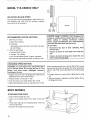
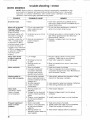
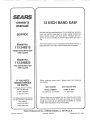
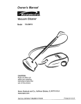
Save This Manual
For Future Reference
Model No.
1t 3,248212
113.248212
Single
Speed
with
Band
Saw
Leg Set
Nlodel No.
113.248322
Two
Speed
with
Band
Saw
113_248322
Leg Set
Serial
Number
Model
and
serial
numbers
may be found at the
hand side of the base,.
You
model
should
record
and serial
left-
12 BNCH BA
SAW
both
number
in
a safe place for future use.
o assembBy
o operating
o repair parts
FO YOU
SAFETY
READ ALL
iNSTRUCTiONS
CAREFULLY
\
.J
.J
Sears,
Part No..SP5779
Roebuck
and
Co.,
Hoffman
Estates,
IL. 60179
U.S.A.
Printed in US A
FULLONEYEAR
WARRANTY
If within one year from the date of purchase,
ON CRAFTSMAN
this Craftsman
BAND SAW
Saw fails due to a defect
in material
or workmanship,Searswillrepairit, free ofcharge.
WARRANTYSERVICEtS AVAILABLEBYSIMPLYCONTACTINGTHE NEARESTSEARSSERVICE
CENTER/DEPARTMENT
THROUGHOUTTHE UNITEDSTATES.
Thiswarrantyapplies only whilethis productis used in the UnitedStates,
Thiswarrantygivesyou specificlegalrights,andyou may also haveotherrightswhichvaryfrom
stateto state,.
Sears_ Roebuckand CO.., Dt817WA Hoffman Estates, IL 60179
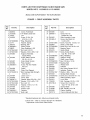
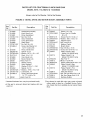
TABLE OF CONTENTS
Sectton Tttle
Page Number
Location and Function of Controls ...............................27
Safety Instructions for Band Saw ............................................
2
On-Off Switch ............................................................. 27
Glossary of Terms for Woodworking ..............................
6
Electrical Connections .................................................................
6
Tilting Head for Bevel Cut ................................................
27
General Information ..............................................................................
8
Adjusting Bevel Lock Knob ..............................................
27
Model Description .....................................................................
8
Basic Band Saw Operation ....................................................
28
Unpacking and Checking Contents ..................................
8
Circle Cutting ..............................................................................
31
Sawdust Collection ..................................................................
31
Assembly and Alignment .........................................................
11
Assembling Leg Set .........................................................
1!
Installing Sanding Attachment ......................................
32
Adjusting Leveling Feet .....................................................
13
Installing the Sanding Belt ..............................................
32
Attaching the Handwheel ..............................................
13
Installing 1/16" Blade and
Blade Guides ............................................................................
33
Mounting the Motor ..................................................................
14
Connecting the Motor _.............................................................
17
Scrolling .....................................................................................
34
Recommended Accessories ..............................................
36
Selecting Blade Speed .................................................
18
Maintenance ..................................................................................
36
Recommended Speed Settings ......................................
18
Changing Speed Settings ...................................................
18
Trouble Shooting - All Models .........................................
37
Attaching Trim Caps ................................................................
18
Trouble Shooting - Motor ..................................................
38
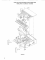
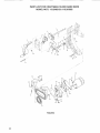
Parts Lists ................................................................................................
40
Getting to Know Your Band Saw .....................................
19
Installing the Blade ..................................................................
20
Drive Assembly .....................................................................
40
Aligning the Blade and
Base Components ..............................................................
42
Blade Guide Assemblies ....................................................
22
Bevel Drive and Motor Mount
Mounting the Front Table ................................................
24
Assembly Parts ..................................................... 44
Squaring the Blade to the Table ..........................................
26
Leg Set ................................................................................
46
Adjusting Front Table ..............................................................
26
for Band Saw
Safety Instructions
SAFETY
SIGNAL
WORDS
Assembly and alignrnent,
DANGER: means if the safety information is not followed someone will be seriously injured or killed
WARNING:
means if the safety information is not
followed someone could be seriously injured or killed.
Learn the use and function of the ON-OFF switch,
bevel handwheel, bevel lock knob, blade guides,
backup bearings, guide bar lock knob, and blade
guard (See page 19 .)
CAUTION: means if the safety information is not followed someone might be injured
• Review and understanding of all safety instructions
and operating procedures in is manual
Safety is a combination of common sense, staying alert
and knowing how your band saw works. Read this
manual to understand this saw,
• Review of the maintenance
(See page 36.)
BEFORE
WARNING:
USING THE SAW:
,
(See pages 11 - 18)
methods for this saw,
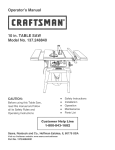
Read the following WARNING labels found on the front
of the saw:
To avoid mistakes that could cause
serious, permanent Injury, do not plug the saw In
until the following steps are completed.
t Read men_e] before using saw
2 Wear safely goggles that meet ANSi
Z87o1 standards
3. Be sure blade Is Installed with teelh
5. Do nat remove tammed cutoff pieces until
blade has stopped,
6. Maintain proper adjustment of blade tension,
blade guides, and thrust beadngs
pointing down.
4. Keep lingers away frQm the moving blade.
7 Ad|usl uppor guide to just clear the wosd
8, Hold workplace firmly against the labla_
9, Turn power off and walt for biade 1ostop
before adjusting or servicing
10, Malnlaln 1116 inch maximum distance
between table and sanding belt,
WHEN
INSTALLING
OR MOVING
THE SAW
AVOID DANGEROUS ENVIRONMENT. Use the saw in
a dry, indoor place protected from rain Keepwork area
well lighted
To avoid injury from unexpected
saw movement:
• Put the saw on a firm level surface where there is
plenty of room for handling and properly supporting
fl_e workpiece
• Support the saw so the table is level and the saw does
not rock
Bolt the saw to the floor or work surface if it tends to
slip, walk, or slide during operations like cutting long,
heavy boards.
• Turn saw ofl and unplug cord before moving the saw
To avoid injury or death from electrical
broken pads,
stable mounting, and
• any other conditions that may affect the way the saw
works
If any part is missing, bent, or broken in any way, or any
electrical parts don't work properly, turn the saw o!l and
unplug the saw.. REPLACE damaged, missing, or failed
parts before using the saw again
MAINTAIN TOOLS WITH CARE Keep ll_e saw clean
for best and safest performance
Follow instructions for
lubricating
REMOVE ADJUSTING KEYS AND WRENCHES
tool before turning it on
To avoid injury from jams, slips or thrown
broken blades:
shock:
from
pieces or
Use of right Made size, style and cutting speed tor the
material and the type ol cutting you plan to do
GROUND THE SAW. This saw has an approved 3conductor cord and a 3-prong grounding type plug..
Use only 3-wire grounded outlets rated t20 volts, 15
amperes (amps) The green conductor in the cord is
the grounding wire To avoid electrocution, NEVER
connect the green wire to a live terminal
USE ONLY RECOMMENDED ACCESSORIES, (See
page 36) Consult this Owner's manual for recommended accessories
Follow the instructions that
come with the accessories.. The use of improper
accessories may cause risk of injury to persons
• Make sure your lingers do not touch the plug's metal
prongs when plugging or unplugging the saw
•
To avoid back injury, get help or use recommended
casters when you need to move the saw Always get
help if you need to lift the saw,
• Make sure the blade guides and thrusl bearings are
properly adjusted
NEVER STAND ON TOOL. Serious injury could occur
il the tool tips or you accidentally hit the cutting tool. Do
not store anything above or near the toot where anyone
might stand on the tool to reach them°
BEFORE
EACH
USE:
Make sure the blade teeth point downward, toward
the table
• Make sure the blade or sanding belt tension is properly adjusted
,
Before sanding, adjust the sanding platen 1oclearthe
table by no more than t/8 of an inch
• Make sure the bevel clamp is tight and no parts tlave
excessive play
Inspect your saw°
DISCONNECT THE SAW.. To avoid injury from accidental starling, unplug the saw, turn the switch oil and
remove the switch key before changing the setup, removing covers, guards, blade or sanding belt.
CHECK DAMAGED
PARTS,, Check for:
To avoid accidental blade conlact, minimize blade
breakage and provide maximum blade supporl, always adjust the upper blade guide and blade guard lo
just clear the workpiece
KEEP WORK AREA CLEAN
Cluttered areas and
benches invite accidents. Floor must nol be slippery
alignment ol moving parts,
• binding of moving parts,
To avoid burns or other fire damage, never use tf_e saw
near flammable liquids, vapors or gases
3
Plan ahead to protect your eyes, hands, face
and ears.
KNOW YOUR SAW. Read and understand the owner's
manual and labels affixed to the tool.. Learn its application
and limitations as well as the specific potential hazards
peculiar to this tool..
To avoid injury from accidental contact with moving pars,
don't do layout, assembly, or set up work on the saw
while any parts are moving.
AVOID ACCIDENTAL STARTING. Make sure switch is
"OFF" before plugging saw into a power outlet
Plan your
work.
• Use model 113248212 to cut and sand only wood,
wood like products and plastics.
CAUTION: To avoid blade breakage, fire or other]
damage to the saw, NEVER use model 113.248212
to cut metals.
° Use model 113248322 to cut and sand only wood,
wood like products, plastics and non-ferrous metals
CAUTION: Model 113_248322 is NOT designed for'
cutting or' sanding ferrous metals like iron or steel.
When cutting or sanding non-ferrous
metals
(brass, copper' and aluminum, etc.), metal shavings
can react with wood dust and start a fire.
* Noise levels vary widely= To avoid possible hearing
damage, wear ear plugs or muffs when using saw for'
hours at a time.
J
° For dusty operations, wear a dust mask along with the
safety goggles.
Inspect your' workpiece.
Make sure there are no nails or foreign objects in the
part of the workpiece to be cut
Use extra caution with large, very small or' awkward
workpieces:
To avoid this:
Disconnect any type of dust collecting
from the saw.
hose
Remove all traces of wood dust from inside the
saw.
.
* Wear nonslip footwear
° Roll long sleeves above the elbow
to do a job it was designed to do..
.
• Do not wear loose clothing, gloves, neckties or jewelry
(rings, wrist watches).. They can get caught and draw
you into moving parts
* Tie back long hair
- USE THE RIGHT TOOL.. Don't force tool or attachment
•
Any power saw can throw foreign objects into the eyes..
This can cause perrnanent eye damage. Wear safety
goggles (not glasses) that comply with ANSI Z871
(shown on package) Everyday eyeglasses have only_
impact resistance lenses. They are not safety glasses.
Safety goggles are available at Sears retail catalog
stores Glasses or goggles not in compliance with ANSI
Z87.1 could seriously hurt you when they break
Remove all metal shavings from inside the saw
before sawing wood again.
• Use extra supports (tables, saw horses, blocks, etc.)
for any workpieces large enough to tip when not held
down to the table top
NEVER use another person as a substitute for a table
extension, or as additional support for a workpiece that
is longer or wider than the basic saw table, or to help
feed, support or pull the workpieceo
When cutting irregularly shaped workpieces, plan your
work so it will not slip and pinch the blade.. A piece of
molding for example, must lie flat or be held by a fixture
of jig that will not let it twist, rock or slip while being cut,.
Dress for safety
Properly support round material such as dowel rods, or
tubing. They have a tendency to roll during a cut,
causing the blade to "bite". To avoid this, always use a
"V" block or' clamp the work to the miter gage..
° Cut only one workpiece at a time.
• Cleareverythingexceptthe workpieceandrelated
supportdevicesoffthetablebeforeturningthesaw
Before freeing any jammed material:
, Turn switch "OFF"
on
Plan the way you will hold the workpiece from start
to finish,
Do not hand hold pieces so small that your fingerswiil go
under the blade guard Use jigs or fixtures to hold the
work and keep your hands away from the blade
SECURE WORK
Use clamps to hold work when
practical, if'soften safer than using your hand, and frees
both hands to operate the tool
,
Remove switch key
•
Unplug the saw
• Wait for all moving paris to stop
When backing up the workpiece, the blade may bind
in the kerf (cut)_ This is usually caused by sawdust
clogging up the kerr or because the blade comes out
of the guides_ If this happens:
Avoid awkward operations and hand positions where a
sudden slip could cause fingers or hand to move into the
blade or sanding surface
,
DON'T OVERREACH
•
Keep good footing and balance
Turn switch"OFF"
• Remove switch key
Unplug saw
• Wait for all moving parts to stop
,
WHENEVER
Remove band saw cover
SAW IS RUNNING.
• Stick llat blade screwdriver or wedge into the kerr
WARNING: Don't let familiarity (gained from frequent use of your band saw) cause a careless
mistake. A careless fraction of asecond isenough
to cause a severe Injury,
Before starting your cut, watch the saw while it runs if
it makes an unfamiliar noise or vibrates a lot, stop
immediately Turn the saw off Unplug the saw Do not
restart until finding and correcting the problem
KEEP CHILDREN AWAY.
Keep all visitors a safe
distance from the saw_ Make sure bystanders are clear
of the saw and workpiece
DON'T FORCE TOOL It will do the job better and safer
at its designed rate. Feed the workpiece into the saw
blade only fast enough to let it cut without bogging down
or binding.
• Turn the upper wheel by hand while backing up the
workpiece,,
Before removing loose pieces from the table, turn saw
off and wait for all moving paris to stop,
BEFORE
LEAVING
THE SAW:
Wait for all moving parts to stop
Make workshop child-proof.. Lock the shop Disco nnect
master switches. Remove the yellow switch key. Store
it away from children and others not qualified to use the
tool
gtossary
of terms for woodworking
Both ModeUs
Beveling
An angle cutting operation made through the face of the
workpiece._
Compound Cutting
A simultaneous bevel and miter crosscutting operation.
Crosscut
A cutting operation made across the width of the workpiece
FPM
Feet per-minute. Used in reference to surface speed of
blade
Freehand (ad used for band saw)
Performing a cut without the workpiece properly supported on the work table
Gum
A sticky, sap based residue from wood products.
Kerr
The material removed by the blade in a through cut or the
slot produced by the blade in a nonthrough or partial cut.
Kickback
An uncontrolled grabbing and throwing of the workpiece
back toward the front of the saw
Leading End
The end of the workpiece which, is pushed into the cutting tool first
Mitering
An angle cutting operation made across the width of the
workpiece
Motor Specifications
Push Stick
A device used to feed the workpiece through the saw during narrow ripping type operations and helps keep the
operator's hands well away from the blade.
Resaw
A cutting operation to reduce the thickness of the workpiece to make thinner pieces
Resin
A sticky, sap based substance that has dried..
Ripping
A cutting operation along the length of the workpiece.
Sawblade Path
The area of the worktable or workpiece directly in line
with the saw blade
Set
The distance the tip of the sawblade tooth is bent outward from the face of the blade..
Trailing End
The workpiece end last cut by the blade
Workpiece
The item on which the cutting operation is being performed The surfaces of a workpiece are commonly
referred to as faces, ends, and edges.
Worktable
The surface on which the workpiece rests while performing a cutting or' sanding operation..
and ERectrican Requirements
BOTH I ODEL$
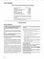
POWER SUPPLY AND MOTOR SPECIFICATIONS
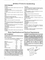
Motor Specifications
The A-C motor used in this saw is a capacitor' start, nonreversible type having the following specifications:
113 248322
1t3 248212
Rated HP ......................................................
5/8 ......................
1/2
Maximum Developed H P.................1-1/8 .........................
1
Voltage .........................................................
120 ...................120
Amperes ............................................ 7 9 ....................79
Hertz (Cycles) ...........................................
60 ......................
60
Phase ...................................................
Single .................
Single
RPM ..........................................................
1725 ...............1725
Rotations of Shaft .............................
Clock-. .............Clockwise
wise
WARNING: To avoid electrical hazards, fire hazards
or damage to the tool, use proper circuit protectiono Your saw is wired at the factory for 120v operation. Connect to a 120v, 15-amp, branch circuit
and use a 15-amp fuse or circuit breaker. To avoid
shock or fire, if power cord is worn, cut or damaged
in any way, have it replaced immediately,
WARNING: To avoid electrical shock, do not permit
fingers to touch the terminals of the plug, when
installing or removing the plug to or from the outlet.
WARNING: If not properly grounded this power tool
can cause electrical shock-particularly when used
in damp locations close to plumbing. If an electrical shock occurs there is also the potential of a
secondary hazard such as your hands contacting
the sawblade.
Not all outlets
are properly
grounded. If you are not sure that your' outlet is
properly grounded, have it checked by a qualified
electrician.
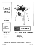
Your unit has a plug that looks like the one shown below
3-Prong
Rug
Properly
Grounded
Outlet
Grounding
Prong
This power tool is equipped with a 3-conductor cord and
ground type plug listed by Underwriters' Laboratories.,
The ground conductor has a green jacket and is attached
to the tool housing at one end and to the ground prong in
the attachment plug at the other end
2, If the motor fails to start, turn the power switch to the
"OFF" position immediately Unplug the tool,, Check the
sawblade to make sure it turns freely If the blade is
free, try to start the motor again If the motor still does
not start, refer to the "Motor Troubleshooting Chart",,
This plug requires a mating 3-conductor
outlet as shown above
3 If the motor suddenly stalls while cutting wood, turn the
power switch off, unplug the tool and free the blade
from the wood Tile motor may now be restarted and
the cut finished
grounded type
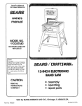
WARNING: To maintain proper tool grounding
whenever the outlet you are planning to use for this
power tool is of the two prong type, do not remove
or alter the grounding prong in any manner. Use an
adapter as shown and always connect the grounding prong to known ground.
Have a qualified electrician replace the two prong outlet
with a property grounded three prong outlet..
An adapter as shown is availabfe for connecting the plug
to a 2 prong receptacle.. The green grounding lead
extending from the adapter must be connected to a permanent ground such as properly grounded outlet box.,
Grounding Lug
,_ ,_.....
/
!
_MakeSureThisls
Y_'-_-_
iI Connected to a
:-l@T oo o
4 Frequent "blowing" of fuses or tripping of circuit breakors may result if:
a Motor is overloaded - Overloading can occur if you
feed too rapidly,.
b Low Voltage - Although the motor is designed for
operation on the voltage and frequency specified on
the motor nameplate, normal loads will be handled
safely on voltages not more than 10% above or
below the nameplate voltage, Heavy loads, however,
require voltage at motor terminals equals the voltage specified on nameplate
5,, Motor troubles may be traced to loose or incorrect connections, overload, reduced input voltage (such as
small size wire in the supply circuit) or to overly long
supply circuit wire Always check the connections, the
load and the supply circuit whenever motor fails to perform satisfactorily Check wire size and length with the
Wire Size Chart below,
Wire Sizes
Adapter
NOTE: The adapter illustrated is for use only if you
already have a properly grounded 2-prong receptacle
NOTE: Make sure the proper extension cord is used and
is in good condition
Motor
Safety
Protection
Note: To avoid motor damage this motor should be blown
out or vacuumed frequently to keep sawdust from interfering with normal motor ventilation,
1,,This tool should be connected to a 120v, 15 amp
branch circuit with a 15 amp fuse or circuit breaker
Failure to use the proper size fuse can result in damage to the motor,,
The use of any extension cord will cause some loss of
power, To keep this to a minimum and to prevent overheating and motor burn-out, use the table below to determine the minimum wire size (AW,G,) extension cord,,
Use only 3-wire extension cords which have 3-prong
grounding type plugs and 3-pole receptacles which
accepts the tools plug
CAUTION:
electrical
increased
voltage to
For circuits that are farther away from
service
box, the wire size must be
proportionately in order to deliver ample
the saw motor,
Length of the
Conductor
0 : 25 Fil
26 - 50 FL
A.W.G.
............14................
12
7
genera
information
BOTH MODELS
1, This manual is for the following models - 113.2482t2
and 113248322. All sections are labeled with the correct model number: Follow ONLY instructions that are
meant for your model saw,.
2. If you are missing any part(s) while putting your saw
together; do not continue assembly.. Contact your
Sears Service Center or Retail Store and get the missing part(s) before continuing assembly or trying to use
the saw.
Model Description
Model 113.248212; Manual Band Saw; 18 x 23 inch work
table; single speed; 1/2 H P,.motor' that develops 1 H R,;
legseL
Model 113248322;Manual
Band Saw; 27 x 23 inch work
table; two speed; 5/8 H..P motor that develops 1-1/8 H. P;
legset°
Complete parts lists are located at the end of this manual Use these lists to identify the number of any missing part.
3. Sometimes small parts get lost in packaging rnateriaIs,.
Do not throw away any packaging until your' saw is put
together If your are missing a part, check packaging
before contacting Soars..
unpacking
and checking
contents
B@TH M@D LS
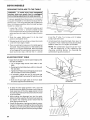
TOOLS
NEEDED
COMBINATION
SQUARE
MUST
BE TRUE
STRAIGHT
EDGE OF
BOARD
3/4-iNCH
THICK
THIS
EDGE MUST BE
MEDIUM
PE_CTLY
SCREWDRIVER
STRAIGHT
F
!
tf2 PHILLIPS
f
SCREWDRIVER
I
DRAW
7/16
_{L(
3/8
9/16"
_
WRENCH
LINE
WRENCH
WRENCH
LIGHT
ALONG
SQUARE
t
ON BOARD
THtS
EDGE
I
_"_'T-
L_
7/16" SOCKET
3/8" SOCKET
9/16"
1.8
5/32
HEX
HEX
L
_
_
/
_
WRENCH
'L WRENCH
_
SOCKET
/
WRENCH
SHOULD
SQUARE
WARNING:
To avoid injury from unexpected
starting or electrical shock, do not plug the saw in
until all assembly and alignment steps are complete. The power cord must remain unplugged
whenever you are working on the saw.
Unpacking and Checking Contents
1 Separate all "loose parts" from packaging materials
and check each item with "Table of Loose Parts" to
make sure all items are accounted for, before discarding any packing material
8
BE NO GAP OR OVERLAP
HERE WHEN
IS FLIPPED
OVER iN DOTTED
POSITION
WARNING: If any parts are missing, do not attempt to assemble the band saw, plug in the
power cord, or turn the switch on until the missing
parts are obtained and are Installed correctly.
2, Remove front table and front cover first while saw is
being unpacked To remove the front cover, pull the
cover at the neck and underside of throat area
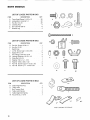
TABLE
ITEM
A
B
C
D
E
F
G
H
1
DESCRIPTION
OF LOOSE
PARTS
QTY.,
Motor .......................
1
Basic Saw Assembly ..................
Owners Manual ....................
Trim Cap, L H ...............
Trim Cap, R H .............................
Leg ...............................
Lower Stiffener ..............................
1
1
1
1
4
4
Sanding Platen ......................................
Pofy "V" Drive Belt ................................
1
1
J
K
L
Pulley .................................
Loose Parts Bag
containing the following items:
Band Saw Blade 1/4 x 80 ........
Sanding Belt 1/2 x 80
Handwheel Assembly
Bag of Loose Paris ....................
Leg Channel .....................
1
t
!
1
3
1
NOTE: To avoid damage to the band saw leave it
laying on its left side until you are ready to mount it
to the leg set or cabinet To prevent scratching the
finish, lay a piece of the packing box under the saw
C
D
E
G
B
I
I
K
9
BOTH
MODELS
LIST
PARTS
IN BAG
DESCRIPTION
QTY.
Truss Head Screw 1/4-20 x 12 ................
Lockwasher, External 1/4
............
Hex Nut 1/4 -20
.....
32
32
32
ITEM
A
B
C
D
E
F
OF LOOSE
Leveling Foot ........
Hex Jam Nut 3/8-16 .................
Bracket Leg
............
4
8
4
F
_
G
LIST OF LOOSE
ITEM
G
H
1
J
K
L
M
N
O
O
P
©
PARTS
IN BAG
DESCRI PT1ON
Pan Hd Screw 10-32 x 2
He;< Nut 10-32 ......................
QTY,,
.............
i
1
Switch Key .................
Lo Hd. Screw Cap 114-20 x 518 ............
Spacer #10 x 1/4 ........................
Hex Flange Lock Nut 10-32 .....
Locking Setscrew 114-20 x 112
.........
Wing Nut 5116-t8 .........
Wasl]er 7/32 x 1 x 1-1/t6 ....................
Washe[ 13t64 x 518 x 1/32
..............
Pan Hd Screw Type TT 10-32 x 3!8 ......
Hex Hd Screw Ty TT 114-20 x 5t8
.........
1
2
4
4
3
1
1
2
2
4
O"
LIST
ITEM
R
S
T
U
V
W
OF LOOSE
PARTS
IN BAG
DESCRIPTION
Table Alignment Key
Table Latch
Belt Tension Stud
Table Latch Spring
Table Alignment Spring
Key 3!16 Sq x I5/16
QTY,.
R •
.......
....
....
T
2
'_NOT SHOWN
10
P
TO SCALE
assembay and aSignntent
BOTH
MODELS
ATTACHING
LEVELING
FEET
From the loose parts bag find tf_e 1ollowing hardware:
ITEM
A
B
C
DESCRIPTION
Support Brackel
........................
Leveling Feet
.......
Hex Nut318-16 .........
From the loose parts find the following items:
D Leg
........
QTY.
4
4
8
_B
C
4
®
1 Mount floor leveler support brackets inside legs,
Line up the three tabs on brackets with slots on leg
and tap into place Make sure lip on bracket points
up Install the remaining three brackets the same
way
LEG
®
®
2 Put a hex nut on each of the leveling feet and screw it
down towards the rubber foot,,
3,, Put the leveling feet through the holes in the bottom
of the floor leveler support brackeL
4,, Put another hex nut on each of the leveling feet and
hand tighten until they are next to the support bracket
WARNING: After the legset has been attached to
the basic saw assembly, it will be necessary to
adjust the leveling feet so the saw does not rock.
HEXNUTS
SUPPORT
BRACKET
LEVELING
FOOT
I1
BeTH
MODELS
ATTACHING
LEG SET
¢
From the loose parts bag find the following hardware:
Item
A
B
C
Description
Truss Head Bolts 1,/4-20x I/2
Lockwashers External V4
Hex Nuts V4-20
.....
Qty,,
32
32
32
From the loose parts find the following items:
D
E
F
Leg Channel
.
Legs (with attached support brackets and
leveling feet)
Lower Stiffeners
1
4
4
E
'_NOT SHOWN
FRONT
SWITCH
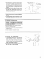
t Lay a piece of cardboard on the floor to keep from
scratching the saw.
TO SCALE
FRONT LEGS AND
CHANNEL ARE
ATTACHED HERE
SIDE
LEG
2 Position the basic saw assembly on the floor as
shown below The back cabinet of the saw should be
laying flat on the floor it may be necessary to have
someone help you lift the saw.
REAR LEGS ARE
kTTACHED HERE
FLOOR
SAW
Mount the two front legs to the basic saw assembly
using truss head bolts, lockwashers, and nuts.
Make sure that the four (4) holes in each corner of
the saw line up with the four (4) holes in the top of
each leg At this time only put bolts through thesides
of the saw assembly notthe front Only fingertighten
nuts
4 Position the leg channel inside the legset as shown
Fasten the channel piece, leg, and saw together
with two (2) truss headbolts on each side.. The
threaded section of the bolts should point towards
the inside of the basic saw assembly Put a lockwasher and hex nut on each bolt.. Finger tighten nuts
at this time
CHANNEL
LEG
i--j
-_
TRUSS
'_"-" HEAD
SCREW
LOCKWASHER
Truss head
12
screw
iockwasher,
hex nut
and #ont
channe/
ptece
5 Usetrussheadbolts,tockwashers,
andhexnutsto
mountthetwo(2)rear legs to the basic saw assembly It may be necessary to slightly tilt the saw assembly backwards in order to get the four (4) holes in
each corner of the saw to line up with the four (4)
holes in the top of each leg Finger tighten nuts at
this time
6 Attach the four (4) lower stiffeners to the legs Two (2)
truss head bolts, washers, and hex nuts are required to hold each end of a lower stiffener in place
Only hand tighten hex nuts
7, Go back with a 7/_6wrench or socket and tighten aft
hex nuts.
8 Carefully lift the saw into its normal position It may
be necessary to have someone help you in order to
avoid damaging the saw,,
ADJUSTING
LEVELING
FEET
WARNING: To avoid injury from unexpected saw I
or work movement, leveling feet must be adjusted
so that saw does not rock.
I
To adjust leveling feet so the saw will sit properly:
I Move saw to desired location,
2 Raise or lower leveling foot by turning it clockwise or
counterclockwise,
3 Tighten nuts to lock leveling foot in place
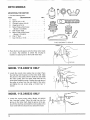
ATTACHING
THE
HANDWHEEL
1 From loose parts bag find one (1) pan head screw
10-32 x 2 and one (1) hexnut
Install the handwheel Reach inside the base to the back side of
the bevel mechanism and put the nut in place
Hold the nut in place with a finger Install the
screw through the center of the handwheel and
tighten with a phillips screwdriver
2 Hold the handle and pull the red release button
with your finger to close the handle
13
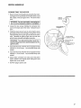
BOTH MODELS
MOUNTING
THE MOTOR
A-,t-
1, Find the following parts:
ITEM
DESCRIPTION
A
B
C
D
E
F
G
H
i
QTY.
Motor .......................................................................... 1
Spacer (#10 x 1/4) .................................................. 3
Flanged Locknut #10-32 ...............................................
4
Wing Nut 5/16-18 .............................................................
1
Motor Pulley w/Set Screw
(Model ! 13,,248322) ....................................................
1
Belt Tension Stud .......................................................1
Motor Pulley w/Set Screw
(Model 113248212 .......................................
t
Poly "V" Belt ............................................................. 1
Key 3/16 Sq. x 15/16 .........................................................
1
*NOT
SHOWN TO SCALE
5PACER
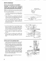
2, Place the three (3) spacers onto the three motor studs
as shown, Pay attention to where the oil plug is
located,, no spacer goes on the fourth motor stud..
I
MODEL 113.248212
ONLY
3 Locate the correct motor pulley (has no step), Place
the shaft key into the groove on the motor shaft Align
the groove in the pulley with the shaft key and install
the motor pulley onto the motor shaft with the set
screw boss toward the motor,. Position the outer face of
the pulley w inches from the end shield of the motor
and tighten the set screw using a 1/8-inch hex "L"
wrench,
MODI tL t13.288322
ONLY
4, Locate the correct motor pulley (Model 113248212
has "one-step" pulley),, Place the shaft key into the
groove on the motor shaft, Align the groove in the pulley with the shaft key and install the motor pulley on the
motor shaft with the setscrew boss toward the motor.,
14
OIL
PLUG
BOTH
M@@EL
5,, Place the Poly "V" belt into the motor mount as
shown on the underside of the band saw
6 Look atthe motor mount and find the slot that is narrower than the other three. When mounting the
motor, the motor stud without a spacer goes into this
slot.
MOTOR
MOUNT
NARROW
SLOT
SPACERS
7 Carefully position the motor so that the poty "V" belt
is around the motor pulley and the four motor studs
align with the slots in the motor mount
8 Push motor studs through and install the flanged
lock nuts to the three (3) motor studs with spacers
Start the flanged nuts by hand only at this time
MOTOR
MOTOR
MOUNT
MOUNT
9. Install the threaded stud through the hole in the
lower leg of the motor mount and over the motor stud
as shown
THREAOEO
STUD
15
MOTOR
BOTH
MOUNT
MODELS
10 Install a flanged lock nut onto this motor stud
Tighten the flanged lock nuts, using a 3/8-inch
wrench, until almost tight, It will be easier to tighten
lock nuts if the head is tilted to approximately 45 °
See page 34 for instructions on tilting head,
FLANGED
LOCK
NUT
NOTE: Do not over-tighten the flange nuts The motor
should slide in the grooves to allow tensioning of the
belt
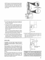
11 Install the wing nut on the threaded stud
t2 Check that the poly "V" belt is on both pulleys being
sure that it is centered on each pulley
t3 Check that the pulleys are in line by sighting down
the side of the large pulley to see if it lines up with the
small pulley If the pulleys are not in line, loosen the
set screw holding the pulley on the motor shaft and
position the puiley, A notch in the small end of the
motoT support is provided for access to the set screw
and belt.
ACCESS
NOTCH
FLANGED
14, Belt tensioning is done by tightening the wing nut
which pulls the motor down The motor slides on the
three (3) spacers and is locked in place by the
flanged lock nuts on the threaded studs
Belt tension is important
Over tensioning may
cause vibration while too little tension may allow the
belt to slip under heavy loads,
15 Alter belt tension is adjusted correctly, tighten all
four flanged locknuts
NOTE: When it becomes necessary to readjust belt
tension, be sure to slightly loosen the flour flanged
lock nuts
TIGHTEN
FLANGE
NUT AFTER
TENSIONING
BELTWITH
WtNGNUT
16
LOCK
NUT
WING
NUT
CONNECTING
THE
MOTOR
1 Next, the motor cord needs to be wired into the motor
Coming from the underside of the table will be a cord
with a black, white and green wire This is the motor
cord_
i WARNING:
saw in until Foryourown
all assembly
TERMINAL
GREEN
safety,
neverplug
the
steps are
completed,.
2 Loosen the two screws holding the connector box
cover on the back side of the motor Swing the cover
open
3 Install the green ground wire by removing the green
grounding screw and inserting it through the round
metal terminal on the green ground wire of the motor
cord Reinstall the green screw into the hole from
which it was removed and tighten securely
WARNING: To avoid electrocution,
never connect but the ground wire (colored green) to the
green screw.
BLACK W_RETO
TERMINALT1
GREEN
GREEN
STRAIN
WIRE
SCREW
RELIEF
)VE
WIRE TO
TERMINAL
T4
4. Insert terminal end of WHITE wire on spade terminal
marked T4 on the motor Push terminal firmly until
seated.
5 Insert terminal end of BLACK wire on spade terminal
marked T1 on the motor Push terminal firmly until
seated,
6 Close motor connector box being sure that power
cord is seated in the largest strain relief groove and
tighten box cover screws,
7 DO NOT plug in power cord
17
MODEL 113.248322
SELECTING
BLADE
ONLY
SPEED
f
The band saw has two speed settings: 3000 FPM for norreal operation and 1500 FPM for-operation
requiring
more control of the workpiece
MOTOR
1500
RPM
RECOMMENDED
SPEED
CAUTION: Model 113.248322 is NOT designed for
cutting or' sanding ferrous metals like iron or steel.
When cutting or sanding non-ferrous
metals
(brass, copper and aluminum, etc.), metal shavings
can react with wood dust and start a fire.
SETTINGS
1 3000 feet per minute
a Basic Wood Cutting
b Resawing
To avoid this:
Most effective with skip tooth, hook tooth, and regular tooth blades
o Disconnect any type of dust collecting hose
from the saw.
o Remove all traces of wood dust from inside the
2. i500 Feet per Minute
a. Intricate Wood Cutting
SaW°
b..Veneers, Tile, Plastics
o
c.. Non-Ferrous Metals (Brass, Copper, Aluminum..)
Most effective with blades that have 15 teeth per inch.
CHANGING
SPEED
3000
RPM
Remove all metal shavings from inside the saw
before sawing wood, again.
SETTING
ing or electric shock, do not plug the saw in. The
power cord must remain unplugged
whenever
WARNING: To avoid injury from unexpected startworking on the saw.
When changing speeds from 1500 to 3000 FPM, remove
the belt from the band saw pulley first. When going form
3000 to 1500 FPM, remove the beit from the motor pulley
first
1 Slightly loosen the four (4) flanged lock nuts that are
holding the motor to the motor mounL
5 Re-apply tension to motor belt by tightening the wing
nut ..
2. Release tension on the poly "V" belt_
6.. After bert tension is adjusted correctly, tighten all four
(4) flanged lock nuts,
3_ Push the motor up to create sJack in the "V" bell
4. While still holding the motor up, reposition the "V" belt
BOTH MODU=LS
ATTACHING
TRIM CAPS
1 Find the left and right trim caps.
2 There are two plastic stubs on the back of each trim
cap.
3. These stubs will snap into matching holes at the front
corner of each saw
4. Snap the left & right trim caps in place
18
............
_
.
, ::_-_,
CAP
getting to know your band saw
B@YH M@D L$
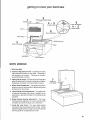
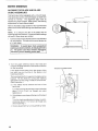
1. Warning Label
2, Tensions Adjustment Knob - Tightening the knob
will increase the tension on the blade Loosening it
will decrease the tension
Clockwise to tension,
counterclockwise to toosen
3o Setting Bevel Angle - Pull the bevel lock knob and
adjust he band saw to the desired angle by turning the
handwheel, then push in the bevel lock to secure
7
GUIDE BAR
LOCK KNOB
4. Blade Guide Adjustment - The guides can be adjusted in or out for various widths of blades and locked
in place by the set screws.
5. Lateral Blade Guide Adjustment - The guides can
be adjusted sideways and locked in position by the
capscrews to prevent the blade from twisting during
operation
6o Blade Backup Bearing Adjustment
- The thrust
bearings can be adjusted in or out for various widths
of blades and locked in place by the setscrews
7. Guide Bar Lock Knob - The upper blade guides
should just clear the workpiece while cutting. Always
adjust the guides before turning on the band saw and
lock the guide bar by tightening tile knob
19
BOTH
MQDIEm=S
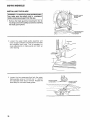
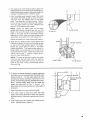
iNSTALLING
THE BLADE
J
GUARD
MOUNTING
SCREW
ing, make sure the power cord is unplugged
I WARNING: To avoid injury from accidental start- I
before removing any part from the saw.
1,, Remove the blade guard by loosening the two (2)
mounting screws with a phillips screwdriver and lifting
the blade guard upward,_
JARD
MOUNTING
2 Loosen the upper blade guide assembly and
lower to approximately
3 inches above rear table
and retighten Iock knob This is necessary to
make adjustments to blade guide and back up
roller bearing
3, Loosen the two capscrews that lock the upper
blade guides using a 1/8-inch hex "L" wrench
and separate them about I/8-inch
Repeat the
same step for the lower blade guides
2O
_I
tf
LockK.o.
_{I_;
¸ _!, __l
f
Ill.........
BLADE
GUIDE
CAPSCREWS
uPPE.BLAOE
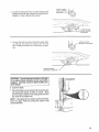
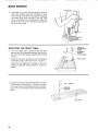
4 Loosen the setscrew which locks the blade guide
support and push the support all the way back
Repeat for lower blade guide support
!l
GU,OSUPPORT
il Z.
!
SETSOR W
=°_
5 Loosen the setscrew which locks the upper back
up bearing and push the bearing all the way
back Repeat procedure for lower back up bearing
WARNING: To avold serious eye Injury or scrapes
if the blade should suddenly uncoil, wear safety
goggles, Carefully uncoll the blade holding it at
arms length.
_f
LOWER BLADE
GUIDE
SUPPORT
SETSCREW
UPPER
BEARING
BLADE
ON
BACKUP
SETSCREW
CENTERED
RUBBER
TIRE
6 Uncoil the blade
7 Place the blade over the wheels with the teeth pointing downwards toward the table as shown. Make
sure the blade is between the blade guides and is in
the center of the rubber tires
NOTE:
If the blade will not reach around both wheels,
lower the upper wheel by turning
counterclockwise
the tension knob
21
BOTH
MODELS
ALIGNING THE BLADE
G UIDE ASSEMBLIES
AND BLADE
This band saw comes equipped with a 1!4-inch blade,
This band saw can be used with blades of width from
1/8qnch to 1/2-inch. The alignment steps must be
followed for proper tension, blade guide, and bearing
adjustments for each different blade.
Refer to the blade usage section for the recommended
blade size for best results during most band saw operafions
NOTE: It is critical to the life of the blade that the
following steps are followed., Premature blade breakage
will result if these steps are omitted.
1 Turn the tension knob until the tension scale indicates
1/4qnch position This wilt set the correct tension for
a 1/44nch blade.
WARNING:
To avoid injury from unexpected
starting or electrical shock, do not plug the saw
in. The power cord must remain unplugged
whenever you are working on the saw.
Turn the upper wheel by hand a few times and
notice if the blade remains in the center of the tire
on the top wheel
TRACKING
ADJUSTMENT
SCREW
If the blade moves away from the center of the
tire while you are turning it, the blade is not
tracking properly
The top wheel shaft is hinged so the blade can be
tracked Tilt the wheel by turning the tracking
adjustment screw using a medium screw driver
(See illustration )
a If the bladel
band saw:
moves toward
the front
,:t..
I
i
of the
Turn the tracking adjustment screw clockwise
about t/4 of a turn, as though you were
tightening it
b If the blade moves toward the back of the band
saw:
,LL
Turn the tracking adjustment screw counterclockwise about 1/4 of a turn as though you
were loosening it
c Check adjustment
22
by turning
wheel by hand
.....
3 The upper and lower blade guides support
the
blade and keep it from twisting
during operation
Adjust blade guide support
whenever
blades are
changed
or replaced
with a different
width
4 Push the blade guide support
toward the blade
and adjust the blade guides
so they are about
1/32-inch
from the deepest
part of the blade
teeth
This deep part is called a gullet
Tighten
the set screw locking
the blade guide support
Turn the upper
wheel, by hand, checking
the
position
of the blade guide support
NOTE:
Letting
the blade
teeth hit the blade
guides
while using the band saw will ruin the
blade
The set of the teeth and the sharpened
edge of the teeth would
be damaged
Proper
adjustment
of the upper and lower blade g_]ide
assemblies
will prevent
this from happening
Repeat procedure
\
BLADE
GUIDE
GULLET
for lower blade guide support
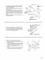
5 Slide the two blade guides evenly against the
sides of the blade Do not push the blade guides
or pinch the blade guides against the blade
Rotate the upper wheel by hand so the blade
travels downward
This leaves proper space for
blade Make sure one guide is not further from
the blade than the other Tighten both setscrews
with a 1/8-inch hex_Lwrench
Repeat procedure for lower blade guides
NOTE: The backup
bearings
support
the blade
from the rear and will spin when the blade is
pushed against
them while you are cutting
As
soon as you stop cutting,
the bearings
should
stop spinning
6 To insure the backup bearing is properly supporting
the blade, push the bearing toward the blade until it
almost touches it Turn the upper wheel, by hand,
checking the backup bearing to make sure it is not
turning,, If the bearing is turning, the blade is too close,,
Move bearing slightly away from the blade and
tighten set screw with 1/8" hex "L" wrench
Turn
upper wheel and recheck the bearing Adjust again if
necessary
BACKUP
BLADE
GUIDE
BEARING
BLADE
BLADEI
i
II
-._-_lJ_,_-----S
BACKUP
-"
GUIDE
I
J
BEARING
_,-" cs uEA"'"G
E
7 Repeat procedure for lower backup bearing,,
8 Turn upper wheel by hand and ctleck the blade
guides and backup bearings to make sure they are
adjusted correctly Make any readjustments i{ neces_
sary
9 Install blade guard and tighten with phillips screwdriver. (See illustration, page 20 )
23
60TH
MODELS
FRONT
t0
COVER
Install the front cover Rest top edge of cover on
two latch springs atong the top edge of back
cover- Swing cover down into position, engaging
the three other-latch
springs
Push the front
cover into position on the back cover Check that
the tip on the front Cover-completely overlaps the
lip on the rear cover
MOUNTING
THE FRONT
LATCH
SPRING
TABLE
1. Turn front table over Locate the two (2) latch
springs, two (2) alignment springs, and the four
(4) t/4-20 x 5/8 hex washer head thread forming
screws
_
'_-'"""_
,
2 install the two latch springs on the front table as
illustrated using a 3/8-inch wrench or socket
/4-20 x 5/8
WASHER HEAD
SCREW
ALIGNMENT
LATCH
SPRING
FRONT
TABLE
Instal! the two aligr]ment springs on the front
table as illustrated using a 3/8-inch wrench or
socket
3 Locate the two (2) oval point setscrews t/4-20 x
1/2 and use an 1/8-inch hex "L" wrench to instalf
in the two holes, as illustrated, but do not allow
the screws to extend beyond the underside of the
table
FRONT
24
TABLE
_
4, Locate the two (2) table latches, two (2) 3ie"long Phillips head self tapping screws, two(2) smail washers,
and one (1) iarge washer
5 Piace front table latch through slot on right side ot
bandsaw frame
TABLE
LATCH
LARGE
WASHER
ON RIGHT
SlOE ONLY
SMALL
WASHER
t TABLE
I
6 Tilt top of front table latch slightly forward and place
large washer between bracket and bandsaw frame,
7, Place self tapping screw through small washer and
attach to table latch Do not completely tighten
screw,
PHtLLtPS
LATCH
HEAD
SELF TAPPING
SCREW
SMALL
8 Attach left side table latch with self tapping screw
and washer as shown
BASE
PHILLIPSHEAD
SELFTAPPING
SCREW
ASSEMBLE
WITH LATCH TO
HIGHEST
AOJUSTING
POSITION
9 Locate the table alignment key and the two (2) 1/420 x 5/8 low head capscrews Install the key under
the rear table miter gage slot and install the two
screws but do not tighten at this time.
KEY
10 Mount the front table to the base as follows:
a, Make sure front table latches are positioned up as
high as they wil! go.,
b, Hold the front edge of the table., Position the rear
edge of the table so that the two flat springs slip
under the two tabs on the rear table.
\
c, Line up the miter gage slots in the front and rear
tables
d Push the front edge of the table backward and
downward until the tabte snaps into position
25
BOTH
MODELS
SQUARING
THE BLADE
TO THE TABLE
i
WARNING:
To avoid Injury from unexpected|
starting, make sure power cord Is unplugged
before making adjustments to band saw parts,
]
To assure repeatability and accuracy, it is important
to square the blade to the table and adjust the 0 °
position stop This will guarantee that the blade will
return to the square position after the head has been
moved for a bevel cut
0sTo,.,..,w
_
J i:
COMBINATION
SQUARE
1 Locate the 1/4-20 x 1/2 oval point setscrew and
use an 1/8-inch hex "L wrench to install it in the
hole located at the left front of the rear table The
setscrew has a lock patch that will make it hard to
turn
2 Slide the upper blade guard
position and tighten knob
to its top
most
3 Retease bevel lock by pulling out bevel lock knob
under feft front edge of table
4 Place a combination square on the table against
the blade Adjust the position of the blade to the
table by turning the handwheel When the blade
is flush against the combination square Iock the
beve! lock knob Use a 1/8-inch hex "L" wrench
ADJUSTING
FRONT
to set the 0 ° stop Turn screw
contact with the frame
until
Unlock bevel lock, bevel the blade, then return to
0 ° position Push in bevel lock knob and recheck
blade to make sure it is square to the table
NOTE: The combination
square must be "true"
-- see the beginning
of the unpacking
and
checking
contents
section for checking
the
combination square procedure
TABLE
Adjust the front table so it is the same height as the
rear table as follows:
a. Lay a straight edge across front table to rear
table
b Gently tap the front table down until it is in tine with
the rear table.
c Tighten the Phillips head self tapping screw once
the front table is in the correct position,.
d If necessary adjust the two (2) oval point set
screws (see Step 3) as needed to help line up the
table.
e. Both the teft and right sides of the front table
should be adjusted simultaneously.
2 To !(eep the miter gage grooves in line, use a flat
blade screwdriver against the head of one of the tow
head capscrews in the miter gage groove to force
the table align ment key fir rely forward into the notch
in the front table
3 While holding the alignment key into the notch,
fighten the other capscrew Remove the screwdriver
and tighten the remaining screw. Check that the
miter gage grooves line up
4. Check the operation of springs arid tabs by removing the front table and reinstalling. Remove the table
by lifting up on two spring tabs under-front edge of
the table until springs are free, then pulling forward
26
it makes
TABLE
LEVELING
SETSCREWS
location
BOTH
MODELS
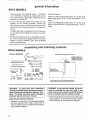
ON-OFF
SWITCH
and function of controts
NOTE: The On-Off switch has a locking feature, This
feature is intended to help prevent unauthorized and
possibly hazardous use by children and others,
1=,Insert yellow key into switch
..........
.......
2.. To turn on, insert finger under end of red switch lever
and pull end out.,
//
3. To turn off switch, push red lever in towards the baser
CAUTION: The locking feature provided is to help
prevent unauthorized use of your saw. Always
remove the yellow key and keep It In a safe place,
To remove yellow key, hold thumb on the end of
red lever to keep switch In "Off" position and pull
yellow key straight out,
2
3
TILTING
HEAD
FOR BEVEL
CUT
1 Unlock bevel lock by pulling out on knob located
under the left front edge of the table
2. Turn handwheel counter-clockwise
to increase
the tilt angle of the blade The bevel scale printed
on the front cover shows the approximate angle
and is read at table level
3 Lock the bevel lock by pushing in on knob until it
is fully seated when desired bevel angle is
reached
BEVEL SCALE
BEVEL
LOCK
KNOB
//
/,
HANDWHEEL
ADJUSTING
MOUNTING
BEVEL LOCK KNOB
2 Use a 9/!6-inch wrench or socket to adjust the
locking nut behind the band saw mounting
frame Turn nut clockwise to tighten
3 Recheck bevel lock knob and readjust if necessa ry
BEVEL
.
The bevel lock knob is factory adjusted and set If
after repeated use it becomes necessary to adjust:
1,, Pull the bevel lock foward and bevel the band
saw to 25 degrees
FRAME
LOCK
KNOB
?
LOCKNUT
HANDWHEEL
27
basUcband saw operation
BEFORE
WARNING:
USING THE SAW:
To avoid mistakes that could cause
serious, permanent injury, do not plug the saw in
until the following steps are completed.
-
MAINTAIN TOOLS WITH CARE Keep the saw clean
for best and safest performance Follow instructions for
lubricating.
REMOVE ADJUSTING KEYS AND WRENCHES from
tool before turning it on
Assembly and alignment (See pages 11 - 18.)
Learn the use and function of the ON-OFF switch,
bevel handwheel, bevel lock knob, blade guides,
backup bearing, guide bar lock knob, and blade
guard (See page 19 )
To avoid injury from jams, slips or thrown pieces or
broken blades:
•
USE ONLY RECOMMENDED ACCESSORIES (See
page 36) Consult this Owner's manual for recommended accessories
Follow the instructions that
come with the accessories The use improper accessories may cause risk of injury to persons
• Review and understanding of all safety instructions
and operating procedures in this manual
•
Review of the maintenance
methods for this saw
(See page 36.)
To avoid back injury, get help or use recommended
casters when you need to more the saw Always get help
it you need to lift the saw..
NEVER STAND ON TOOL Serious injury could occur
if the tool tips or you accidentally hit the cutting tool Do
not store anything above or near the tool where anyone
might stand on the tool to reach them
BEFORE
EACH
USE:
Inspect your saw.
D1SCONNECTTHE SAW_ To avoid injury from accidental starting, unplug the saw, turn the switch off and
remove the switch key before changing the setup,
removing covers, guards, blade or sanding belt
CHECK DAMAGED
PARTS.
Check for:
• alignment of moving parts,
• binding of moving parts,
• broken parts,
• stable mounting, and
• any other conditions that may affect the way the saw
works
If any part is missing, bent, or broken in any way, or any
electrical parts don't work properly, turn the saw off and
unplug the saw RE PLACE damaged, missing, or failed
parts before using the saw again
28
Use of right blade size, style and cutting speed for the
material and the type of cutting you plan to do.
•
Make sure the blade teeth point downward, toward
the table.
.
Make sure the blade guides and thrust bearings are
properly adjusted.
•
Make sure the blade or sanding belt tension is properly adjusted
.
Before sanding, adjust the sanding platen to clear the
table by no more than 1/8 of an inch.
• Make sure the bevel clamp is tight and no parts have
excessive play
To avoid accidental blade contact, minimize blade
breakage and provide maximum blade support, always adjust the upper blade guide and blade guard to
just clear the workpiece.
• KEEP WORK AREA CLEAN
Cluttered areas and
benches invite accidents.. Floor must not be slippery
To avoid burns or other fire damage, never use the saw
near flammable liquids, vapors or gases
Plan ahead to protect your eyes, hands,
face and ears.
KNOW YOUR SAW Read an understand the owner's
manual and labels affixed to the tool. Learn its application and limitations as well as the specific potential
hazards peculiar to this tool.
To avoid injury from accidental contact with moving pars,
don't do layout, assembly, or set up work on the saw
while any parts are moving
AVOID ACCIDENTAL STARTING, Make sure switch is
"OFF" before plugging saw into a power outlet
damage, wear ear plugs
hours at a time
or muffs
when
using saw for
° For dusty operations, wear a dust mask along with the
safety goggles
Inspect your workpiece.,
Make sure there are no nails or foreign objects in the
part of the workpiece to be cut
Plan your work.
o USE THE RIGHT TOOL Don't force tool or attachment
to do a job it was designed to do
• Use model 113248212 to cut and sand only wood,
wood like products and plastics.
CAUTION: To avoid blade breakage, fire or other
damage to the saw, NEVER use model 113.248212
to cut metals.
• Use model 113248322 to cut and sand only wood,
wood like products, plastics and non-ferrous metals
CAUTION: Models 113.248322 is NOT designed for
cutting or sanding ferrous metals like iron or steel.
When cutting
or sanding
non-ferrous
metals
(brass, copper and aluminum, etc.), metal shavings
can react with wood dust and start a fire.
To avoid this:
•
Disconnect
any
from the sawn
type
of dust
collecting
hose
o Remove all traces of wood dust from inside the
saw.
o Remove all metal shavings
before sawing wood again,
from inside the saw
Use extra caution with large, very small or awkward
workpieces:
o Use extra supports (tables, saw horses, blocks, etc)
for any workpieces large enough to tip when not held
down to the table top..
NEVER use another person as a substitute for a table
extension, or as additional support for a workpiece that
is longer or wider than the basic saw table, or to help
feed, support or pull the workpiece.
When cutting irregularly shaped workpieces, plan your
work so it wile not slip and pinch the blade, A piece of
molding for example, must lie flat or be held by a fixture
of jig that will not let it twist, rock or slip while being cut,
Properly support round material such as dowel rods, or
tubing, They have a tendency to roll during a cut,
causing the blade to "bite" To avoid this, always use a
"V" block or clamp the work to the miter gage,
° Cut only one workpiece at a time
° Clear everything except the workpiece and related
support devices off the table before turning the saw.
Plan the way you will hold the workpiece
to finish,
Dress for safety
Any power saw can throw foreign objects into the eyes
This can cause permanent eye damage Wear safety
goggles (not glasses) that comply with ANSI Z87I
(shown on package). Everyday eyeglasses have only
impact resistance lenses They are not safety glasses
Safety goggles are available at Sears retail catalog
stores Glasses or goggles not in compliance with ANSI
Z87 1 could seriously hurt you when they break
from
start
Do not hand hold pieces so small that your finger will go
under the blade guard Use jigs or fixtures to hold the
work and keep your hands away from the blade
SECURE WORK Use clamps to hold work when practical It's often safer than using your hand, and frees both
hands to operate the tool.
° Do not wear loose clothing, gloves, neckties or jewelry
(rings, wrist watches). They can get caught and draw
you into moving parts,
° Wear nonstip footwear.
o Tie back long hair,,
° Roll long sleeves above the elbow
• Noise levels vary widely_ To avoid possible hearing
29
Avoidawkwardoperations
andhandpositions
where
asuddenslipcouldcausefingersorhandtomoveinto
thebladeor sandingsurface
DON'T OVERREACH
ance
Keep good footing and bal-
• Wait for all moving parts to stop
When backing up the workpiece, the blade may bind
in the kerr (cut). This is usually caused by sawdust
clog ging up the kerr o r because the blade comes out
of the guides. If this happens:
• Turn switch "OFF"
WHENEVER
SAW
iS RUNNING.
WARNING: Don't let familiarity (gained from frequent use of your band saw) cause a careless
mistake. A careless fractlon of a second isenough
to cause a severe Injury°
Before starting your cut, watch the saw while it runs If
it makes an unfamiliar noise or vibrates a lot, stop
immediately. Turn the saw off Unplug the saw Do not
restart until finding and correcting the problem.
KEEP CHILDREN AWAY.
Keep all visitors a safe
distance from the saw Make sure bystanders are clear
of the saw and workpiece
DON'T FORCE TOOL It will do the job better and safer
at its designed rate Feed the workpiece into the saw
blade only fast enough to let it cut without bogging down
or binding..
,
Remove switch key
-
Unplug saw
o Wait for all moving parts to stop.
,
Remove band saw cover..
• Stick llat blade screwdriver or wedge into the kerr
,
Turn the upper wheel by hand while backing up the
workpiece.
Before removing loose pieces from the table, turn saw
off and wait for all moving parts to stop..
BEFORE
LEAVING
THE SAW:
Wait for all moving parts to stop
Before freeing any jammed
• Turn switch"OFF"
•
Remove switch key
,
Unplug the saw
3O
material:
Make workshop child-proof. Lock the shop.. Disconnect
master switches. Remove the yellow switch key_ Store
it away from children and others not qualified to use the
tool.
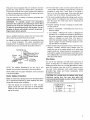
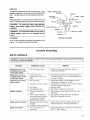
Operation
safety instructions on pages 2- 5 before using the
I CAUTION:
band saw_ For your safety, comply with all the
A band saw is basically a "curve cutting"
is not capable of doing inside cutting
machine
It
Your Craftsman Band Saw is not only capable of the
usual band saw operations, but it can be converted
into a sander as welt You can finish wood, certain
compositions and plastics
It is also used for straight-line
cutting operations
such as crosscutting,
ripping, mitering, beveling,
compound cutting, and resawing
Cross Cutting
Ripping
Mitering
Beveling
Compound Cutting
Circle Cutting
Resawing
Curve Cutting
Extremely Fine Scroll
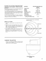
Cutting (Thin Material Only)
BLADE
CIRCLE
CIRCLE
Recommended
Blade Size
(Inches)
I/4, 3/8, 1/2
1/2
1/4, 3/8, 1/2
1/4, 3/8, 1/2
1/4, 3/8, 1/2
See Chart Below
1/2
1/8, 1/4
SELECTION
CUTTING
GUIDE
1/16
FOR
MINrMUM
CUTTING
1 Adjust the upper guides to just clear the workpiece
CIRCLE DIA
2 Use both hands while feeding the work into the
blade Hold the workpiece firmly against the
table Use gentle pressure, and do not force the
work, but allow the blade to cut
3 The smaJlest diameter that can be cut out is
determined
by the width of the blade
For
example, a 1/4-inch wide blade wilt cut a minimum diameter of approximately
1-1/2-inch (.see
chart)
_
2-It2"D
t/2"
BLADE SIZE
SAWDUST
COLLECTION
1 There is an opening provided in the rear of the
bottom cover to attach a 2-1/2-inch hose from a
wet/dry vac to controt sawdust
SAWDUST COLLECTION
OPENING
31
B@'2'I
M@@ELS
INSTALLING
SANDING
ATTACHMENT
WARNING:
To avoid injury from unexpected
starting, make sure power cord is unplugged
before making adjustments to band saw parts.
UPPER
NOTE: Tile sanding belt cuts very rapidly Practice
with some scraps of wood first before you attempt to
sand your actual workpiece
BACKUP
_.NG
SETSCREW
1 To install the sanding belt and sanding platen,
remove the front table, front cover, blade guard,
and the blade
2 Use a 1/8-inch
hex "L" wrench
and remove the
upper and lower right blade guides
The mounting screw used for the upper blade guide will be
used to hold the sanding platen in place
3 Loosen
the setscrews
that hold the upper and
lower backup
bearings
in place and push the
bearings
all the way back Tighten
setscrews
so
bearings
wilt remain
4 Slide the sanding platen into the blade slot in the
table and fasten to the upper blade guide
assembly where the right blade guide mounts it
may be necessary to loosen the left blade guide
and slide it backwards until platen is in place
\
UPPER
BLADE
GUIDE
ASSEMBLY
5 Slide the upper left blade guide towards the
sanding platen and tighten mounting
screw
securely
6 Slide the lower left blade guide towards the
sanding platen until the platen rests 1/8-inch
away from the right edge of the slot in the work
table
INSTALLING
THE SANDING
BELT
1 tnstatl the sanding belt and adjust tension to the
sanding position (The letter "S" on the scale )
2 Rotate the upper wheel by hand (clockwise) to
check the sanding belt tracking Adjust tracking
if necessary (Reference the blade tracking section for tracking procedure )
After tracking the sanding belt if the belt and the
platen do not align loosen the upper blade guide
support and slide the support in or out to align
Then tighten set screws to hold support and
platen in place tt may also be necessary to adjust
the lower blade guide support to align the blade
guide with the sanding platen
NOTE: A new sanding belt will stretch
check the tension
often
32
with use, so
SANDING
BELT
iNSTALLING
1/16 INCH BLADE
AND BLADE GUIDE
(Optional
f
Accessory)
WARNING: To avoid injury from unexpected
starting, make sure power cord ts unplugged
before making adjustments to band saw parts,
FRONT
COVER
_++
I
,"BLADE
GUARD
BLADE
FRONT
TABLE
_i
_
/
1 To install the 1/16+inch blade and non-metallic blade
guides, lirst turn the switch off, remove the safety key,
and unplug the saw, Remove the front table, front
cover, blade guard and blade,
SAFETY
KEY
2 When u sing the 1/16-inch blade, the lower metal blade
guides and lower back up bearings are not used
A Loosen the two cap screws 1hat lock the lower
blade guides using a 1/8-inch hex "L"wrench and
separate them as far as possible Re-tighten these
two cap screws
B Loosen the set screw, which locks the lower back
up bearing and push the bearing to the rear as far
as it will go, Re-tighten the setscrew
LOWER BLADE
GUIDE SUPPORT
SETSCREW
LOWER
BEARING
BACKUP
SETSCREW
CAUTION: Do not usethe metal blade guides
supplied with your band saw when using the
1/16-inch blade_ The metal blade guides
must be removed, Use only the non-metallic
blade guides supplied with the 1/16-Inch
scroll cutting band saw blade,
3 Use a 1!8-inch hex "L" wrench to remove the two cap
screwsthat ho[dthe upper metalblade guides in place
Remove the two metal blade guides
4 Loosen the setscrew that locks the upper back up
bearing,. Push the bearing to the rear as tar as it wilt
go
_,
, /
' i:" ;*++) r ':
UPPER
BLADE GU+DE
CAPSCREWS
I
BEARING
_UPPER
...............
......
5 Locate the special blade guides that are supplied with
lhe 1!16-inch blade, Remove the blade guides and
separate as shown., Discard center piece and plug
Inspect blade guides for burrs and if present remove
with fine sandpaper,
>
SNAP
BLADE
GUIDE
SETSCREW
BACKUP
OFF
DISCARD
POINT
PLUG
33
B@TH M@@ELS
BACKUP
BEARING
6 lnslall the special non-metallic blade guides supplied
wilh the 1!16-inch blade as shown. Separate these
guides as far as they will go
BLADE GUIDE
NON-METALLIC
BLADE GUIDE
NON-METALLIC
l
SEPERATE
GUIDES
AS FAR AS POSSIBLE
7 Uncoi! the 1/i 6-inch blade and place over the wheels
with the teeth facing front of saw and pointing down
towards the table,
\
WARNING:
To avoid serious eye Injury or ]
scrapes if the blade should suddenly uncoil, _I
wear safety goggles. Carefully uncoil the blade
holding tt at arms length.
BLADE
TENSION
KNOB
1
NOTE: If the blade will not reach arour:d both wheels,
lower the upper wheel by turning the blade tension
knob counte[clockwise to the "0" position.
"O"
TURN TO
POSITION
8 Turn the tension knob clockwise to adjust tension to
the sanding position (the letter"S"), This is the correct
tension for the 1/16-inch blade.
TRACKING
9 Turn the upperwheel by hand afewtimes andtumthe
l_acking adjustment screw to keep the 1t16-inch
blade running in the center of the upper wheel,
34
ADJUSTMENT
SCREW
t
NOTE: Because of manufacturing tolerances in band
saws and blades, it may be difficult to track the blade
in the center of the wheel The blade may exhibit a
tendency to wander to the front of the wheel,, If this
condition exists, track the blade on the back hall of the
upper wheel
10 Push the blade guide support toward the blade and
adjust the blade guides so they are even with the
front edge of the blade
BLADE ON BACK
HALF OF UPPER WHEEL
J
11 Position the special non-metallic blade guides right
up against tile 1/16-inch blade and tighten the cap
screws Because these special blade guides can be
positioned right against the blade they prevent the
blade from twisting and give the operator a greater
sense of control
NOTE: The back-up bearing suppods the blade
from the rear and will spin when tlle blade is pushed
against them while you are cutting As soon as you
stop cutting, the bearing should stop spinning
12 To insure the back-up bearing is properly supporting
the blade, push the bearing toward the blade until it
almost touches it, Turn the upper wheel, by hand,
checking the backup bearing to make sure it is not
SCROLLING
.]
BLADE
GUIDE
If the bearing is turning, tl_e blade is too
turning
close Move bearing slightly away from blade and
tighten set screw with 1i8qnch hex "L" wrench Turn
upper wheel and recheck
I
-,,--BLADE
I
BACKUP
1
BEARING
WARNING: For your safety, comply with all the
safety instructions on pages 2- 5 before using the
band saw.
With the special 1/16-inch scrolling blade and nonmetallic blade guides, the band saw is capable of cutting
extremely fine curves in thin material.. The non-metallic
blade guides are made from a special self-lubricating
material that decreases friction between the blade and
guide blocks as well as preventing the blade from
twisting
By using the special blade guides and 1/16-inch scroll
blade, it is possible to do almost everything a scroll saw
can accomplish except interior or piercing cuts The
band saw has the additional advantage of cutting much
faster than the ordinary scroll saw
BEARING
SETSCREW
L
BLADE
GUIDE
WARNING:
The l116-inch scrolling blade operates differently than the conventional
band saw
blade° For best results follow the instructions
in
"Band Saw Scrolling Tips" and the directions on
the back of the 1/16-inch scrolling blade package,
35
BOTH MODELS
Sears
recommends
the following
Accessories
Caster Set for Leg Set ...........................
9-22222, 9-22221
Miter Gauge ..............................................................
9-29929
Hold-Down Clamp for Miter Gauge ....................
9-29928
Stop-Rods for Miter Gauge .............................. 9-29924
Rip Fence .........................................................................
9-23402
Blades and Sanding Belts .............................
See Catalog
Circle Cutting Attachment ........................................
9-23411
Power Tool Know How Handbook .....................9-29117
Sears may recommend other-accessories not listed in
the manual See your nearest Sears store for other
accessories
Do not use any accessory unless you have received
and read complete instructions for its use,
maintenance
B@TH
, I@DEL$
WARNING: Foryour own safety, turn switch "Off"
and remove plug from power source outlet before
matntalning or lubricating your band saw,
Tires
Pitch and sawdust that build up on the tires should be
removed with a stiff brush or' scraped off with a piece of
wood._
NOTICE: To avoid damaging the tires do not use a
sharp knife or any kind or solvent.
ADJUSTING
TRAVEL
ADJUSTING
BAND
SAW
BEVEL
TRAVEL
tf the band saw will not hold its position when at a
bevel angle, and before the bevel lock is locked, or if
it is difficult to change the bevel angle, an adjustment
is necessary to correct the force required to bevel
the band saw
To adjust the force required to bevel the band saw
locate the three (3) capscrews holding the frame to
the motor mount The capscrews are located in the
recessed area behind the hub of the lower wheel at
the 2 oclock, 6 o'clock, and t0 o'clock positions Use
a 3i16_inch hexagonal "L" wrench that has a 4-inch
leg, reach between the spokes of the lower wheel to
the capscrews Adjust the capscrews equally until
the bevel action is smooth and the saw will hold its
position before the bevel lock is locked
36
UPPER
BLADE
GUIDE
If the upper guide bar will not move up and down
easily or falls when the lock knob is loosened,
the
following
adjustment
should be performed
1 Remove
the
washer which
2 Using
which
3 Then
When the tires become worn they should be replaced.
When replacing the tires, stretch them around the wheels
but do not glue them on..
THE
Guide
Bar
is under it
Lock
Knob
a 7/16" socket or wrench
tighten
is under the washer to lust tight
loosen
the same
and
the
the nut
nut 1 turn
4 Move the guide bar up and down to check for
smooth movement while still holding its position
when released
5 Make further adjustments
to the nut as required
to get the guide bar to move smoothly
and hold
its position
when released
6 Reinstall
the washer and Guide Bar Lock Knob
General Maintenance
Keep your band saw clean. Remove the sawdust from
the inside. Vacuum or blow out frequently,
Do not allow filth to build up on the table the guides or
the back-up bearings.
Clean them with Craftsman
Gum and Pitch Remover.
NOTICE: Do not Immerse the back-up bearings
the gum and pitch remover.
In
Put a thin coat of paste wax on the table so that the wood
slides easily while cutting.
Light Bulb
To replace the light bulb remove the front cover° Use a
WIRE CONNECTOR
phillips screwdriver to remove the lens and replace the
_.3REQ)-_
bulb. The light butb is a 25 watt bayonet mount bulb.
SWITCH
BLACK
/
__,
,,-- LAMP CORD
Frequently blow or vacuum out any sawdust from the
.....
_.....
motor.. Follow lubrication instnJction on the motor label
debrts, wear safety goggles
sawdust.
when blowing
BLACKK...................."__3=
L
out
CORD W/PLUG J
_
GREEN--'J
WARNING: To avoid electrocution or fire, immediately replace a worn, cut, or damaged power
cord,
!
BLACK
\--WHITE
[
WHITE___/
1
L_-Z__
_
_
"--MOTOR
CORD
BLACK
Lubrication
WIRING
DIAGRAM
All of the ball bearings are packed with grease at the
factory_ They require no further lubrication.
troubBe shooting
BOTH
M@DSL$
WARNING: For your ownsafety,turn
shooting your band saw/sander.
TROUBLE
switch "Off"and removeplug
Blade does not run in
the approximate center
of the upper wheel.
I Not tracking properly
Blade does not run in
the approximate center
of the lower wheel.
1 Lower wheel not
positioned correctly
shaft
Band Saw slows down
when cutting.
1 Belt too loose
Blade dulls too quickly°
Band saw vibrates,
1
REMEDY
1 Adjust tracking, see Assembly
"Installing the Blade "
on
too small a radius
3 Dull blade
4 Overloading
Blades breaking°
outlet beforetrouble
1
PROBABLE CAUSE
2 Cutting
from powersource
motor
1 Too much tension on
blade
2 Kink in blade caused by
cutting too small a radius
or turning the material
too fast when_cutting _
! Blade guides set too close
to teeth
2 Cutting incorrect material,
1 Too much tension on
motor belt
J
Section,
1 Reposition the wheel by loosening setscrew
and slide wheel in or out to allow blade to run
in center of wheel.
1 Adjust belt tension, see Assembly Section
"Installing and Aligning the Belt"
Stop feeding, and back up the material slightly,
until the band saw speeds up
3 Replace blade
4. Slow down, trying to cut too fast,
{ 1 Adjust tension See Getting To Know Your
I1 Band Saw
I 2 Use correct cutting technique
See Basic
L Band Saw Operation Section
!i1 Adjust upper and lower blade guides See
Assembly Section "Installing the Blade "
l
I 1 Adjust according to "Installing and Aligning
j__ P0._Iy"--V_"
Belt" section, ..................................................................
37
BOTH
trouble shooting--motor
M@#ELS
NOTE: Motors used on wood-working
tools are particularly
susceptible to the
accumulation
of sawdust and wood chips and should be blown out or "vacuumed"
frequently
to prevent interference
with normal motor ventilation
and proper
operation of the centrifugally-operated
starting switch
TROUBLE
PROBABLE CAUSE
I
REMEDY
t
Excessive noise_
1 Motor
t Have motor checked by qualified service
technician
Repair service is available at your
nearest Sears store.
Motor fails to develop
full power. NOTE:
LOW VOLTAGE: (Power
output of motor
decreases rapidly with
decrease in vottage at
motor terminaJs For
1 Circuit overloaded with
lights, appliances and
other motors
1 Do not use other appliances or motors on
same circuit when using the saw
2 Undersize
too long
2 tncrease wire sizes, or reduce length of wiring
See "Motor-Specifications
and Electrical
Requirements" section
3 Request a voltage check from the power
company
qexampte, a reduction of
!10% in voltage causes
wires or circuit
3 General overloading
power company
facilities
of
a reduction power
of 19%
in
maximum
output
tof which the motor is
_capabte, and a reduction
;of 20% in voltage causes
!a reduction of 36% in
_maximum power
ioutput.)
L
=Motor starts slowly
!or fails to come up
i to full speed.
1 Low voltage
2 Windings burned out
or open
3 Starting switch not
operating,
1 Request voltage check from the power
company Check size of circuit wiring
2 Have motor repaired or replaced
3 Blow out sawdust from motor
repaired.
Motor overheats.
I Motor overloaded
2 Improper cooling (Air
circulation restricted
through motor due to
sawdust accumulation.
Starting switch in
motor' will not operate°
1 Burned switch contacts
-1 Have switch replaced
(due to extended hold-in
check from the power
periods caused by low line
voltage, etc )
2 Shorted capacitor
2 Have capacitor tested
3 Loose or broken
3 Have wiring checked
connections.
Motor stalls
(resulting in blown
fuses or tripped
circuit breakers)
Frequent opening of
fuses or circuit
breakers,
38
t
Have motor
I Feed work slower into blade
2 Clean out sawdust to provide normal air
circulation through motor See "Maintenance
and Lubrication" section
and request a voltage
company
and replace if defective
and repaired
Starting switch not
operating
2 Voltage too low to permit
motor to reach operating
speed
3 Fuses or circuit breakers
do not have sufficient
capacity.
!. Have switch replaced
1 Motor overloaded
2 Fuses or-circuit breakers
do not have sufficient
capacity
3. Starting switch not
operating (motor does not
reach speed).
1 Feed work slower into blade.
2 Inst'all proper size fuses or circuit breakers
Check that wiring wilt handle load
2 Request voltage check from the power
company.
3 Install proper size fuses or circuit
breakers
3 Have switch replaced.. Blow out sawdust
notes
39
o
59
PARTS LIST FOR CRAFTSMAN
MODEL
12-INCH
NO'S. 1'I 3.248212
BAND SAW
& 113.248322
Always order by Part Number - Not by Key Number
FIGURE
Key
NO_
Part No.
1 823672
2 9-26595
3 41815
4 816600
5
6
7
8
9
I0
I1
12
STD582062
41711
8200 t 5
823426-2
38879
STD54t431
STD551031
816364
t3
816446
14
!5
16
816437
816350
808380-5
!7
18
19
816433
816453
STD533110
20
21
22
23
24
25
26
27
28
29
816464
818050
8O8447-2
STD551025
STD541425
805552-20
816435
816444
808335-2
STD372252
1 - DRIVE ASSEMBLY
Description
Cover, Front!Scale
1" 1/4" Blade, Band Saw
Tire
Screw, SL Hd Set
5/16-18 x 2-1/8
* Ring, Retaining 5/8
Washer, Spring
* Bearing, Ball
Wheel, Upper
Ring, Retaining 1-3/8
* Nut, Lock 5/t 6-18
* Washer, 21/64 x 5/8 x !/32
Support Assembly,
Upper Wheel
Screw, Blade Tension
3/8-16 x 10-1/4
Knob, Blade Tension
Plate, Support
Screw, Pan Hd,, Plastite
#8 x 3/4
Frame
Plate, Pivot Support
* Bolt, Carriage High Strength
5/16_18 x 1
Latch, Cover -Cover, Rear
Washer, Wave 3/8 x 3/4 x .016
I* Washer, I7/64 x 5/8 x 1/32
* Nut, Lock 1/4
Washer, 17/64 x 1 x 1/16
Knob, t/4-20
Socket, Light
Retainer
* Bulb, Light
Key
No.
PARTS
Part No,
'_ 30"816380
Description
'
Lens
31
808380-1
32
33
816362
815865-2
34
35
36
37
38
39
STD512505
818000
STD502502
818925
816379
STD5II107
*
4O
41
42
43
44
45
46
47
48
49
50
51
52
53
54
55
STD583031
816365
816387
STD580103
STD315238
69059
816349
816358
816377
STD551037
816353
STD503!05
816363
816361
109093
813786-2
*
56
57
58
--
816388
9-22361
816368
SP5779
*
*
*
*
Screw, Pan Hd
Plastite #6 x 3/8
Slide Assembly, Lower
Screw, Hex Wash Hd
1/4-20 x 5/8
Screw, Truss Hd 1/4-20 x 1/2
Guide, Lower Slide
Screw, Soc, Set 1/4-20 x t/4
Bearing Thrust
Guide, Blade
Screw, Socket Button
Cap_ No. 10-32 x 3/4
Ring, Retaining
Support, Guide
Shaft, Lower Wheel
Key, 3/16 Sq.. x I5/16
Bearing, Ball
Wheel, Drive
Follower
Nut, Heavy Square 3/8-16
Indicator, Tension
* Washer, 380 x ..750 x ..03
Spring, Blade Tension
* Screw, Soc.. Set 5/16-18 x 1/2
Slide Assembly, Upper
Lock, Slide
Bolt, Carriage 1/4-20 x 1-3/4
Screw, Pan Cross Hd.
Type "TT" No..8/-32 x 5/8
Guard, Blade
1"Belt, Sanding 1/2 x 80
Platen, Sanding
Owners Manual (Not lilus )
* Standard hardware item May be purchased locally
t Stock Item - May be secured through the Hardware
Department of most Sears Retail Stores,
41
PARTS LIST FOR CRAFTSMAN
MODEL
NO'S. 113.248212
4
1/2
5
17
16
14
5
18
\
9
19
\
28
\
34
.,.jl
j
J
I"""
35
i'
t!
FIGURE 2
42
12-INCH
BAND SAWS
& 113.218322
PARTS LIST FOR CRAFTSMAN
MODEL
12-INCH
BAND SAWS
NO'S. 113.2482'I 2 & 113,218322
Always order by Part Number - Not by Key Number
FIGURE
Key
Noo
Part No.
1 816421
2
816420
3 806036_2
4
816423
5 815868
6 810214-2
7 816371
8 62204
9 STD522505
10 816372
11 STD60t103
i2
13
14
t5
t6
17
STD551210
169123_12
816448
816436
STD375006
816888
2- BASE
Description
Table, Rear
(Model 113 248212 only)
Table, Rear
(Model 113248322 only)
Screw, Locking Set
1/4-20 x 1/2
Cover Base
(Model 113248212 only
Relief, Strain
Screw, Low Hd Cap
t/4_20 x 5/8
Key, Table Alignment
Clip, Cord
* Screw, Hex Wash Hd
t/4-20 x 1/2
Plate, Cover
* Screw, Pan Hd Type "TT"
10-32 x 3/8
* Lockwasher, lnt #I0
Relief, Strain
Cord, w/Plug
Cord, Switch
* Connector, Wire
Cord, Motor
COMPONENTS
Key
No,
Part Noo
18
19
2O
21
22
816434
816417
818529
816370
815865-2
23
24
25
26
818390
27
28
29
30
STD551 012
818777
8161t3
STD610805
31
32
33
34
818569
STD511105
9-22256
STD551010
35
36
818193
818192
816403
STD541110
STD611005
Description
Table, Front
Cover, Bottom
Spring, Table Latch
Spring, Table Alignment
Screw, Hex Washer Hd,,
Type "TT" I/4-20 x 5/8
Base Assembly
Box, Switch
* Nut, Hex 10-32
* Screw, Pan Hd Ty AB 10 x 1/2
(Model I13,248212 only)
* Washer, Large 7/32 x 1 x t/16
Latch, Table
Switch, Locking
Screw, Pan Hd,, Plastite
#8 x 1/2
Gasket
* Screw Pan Cross 10_32 x 1/2
t Key, Switch
* Washer, Small
13/64 x 5/8 x t/32
Cap, Trim, LH
Cap, Trim, R H
* Standard hardware item May be purchased locally,
t" Stock Item - May be secured through the Hardware
Department o! most Sears Retail Stores
43
PARTS LIST FOR CRAFTSMAN
MODEL
12-INCH
NO'S. 113.248212
BAND SAWS
& 113.218322
7
\
6
\
17
_6
24
i°-'"
25
14
37
29
\
33
34
36
/
9
39
42
FIGURE 3
44
PARTS LIST FOR CRAFTSMAN
12-INCH BAND SAW
MODEL NO'S. 113.248212 & 113.248322
Always
FIGURE
Key
No.
Part No.
1
2
3
4
5
6
7
8
9
816499
816386
816381
STD541110
816384
816543
816382
STD571207
815865-2
I0
!1
12
13
14
15
16
17
18
19
20
21
22
23
816348
802392-38
STD551050
815774_3
816360
816359
60208
813024-4
816443
60317
816452
STD551025
STD551125
815992-3
24
60240
3-
BEVEL
order
by Part Number
DRIVE
AND
- Not by Key Number
MOTOR
Description
Handwheel Assembly
Knob, Bevel Lock
Pinion Handwheet
* Nut, Hex 10-32
Gear, Handwheel
Cover, Bevel Gear
Shaft, Bevel
* Pin, Roll t/8 x 3/4
Screw, Hex Washer Hdo
Ty TT 1/4-20 x 5!8
Pinion, Bevel Drive
Spacer 1/2 x 2
* Washer, .507 x t 25 x 125
Rivet, 1/4 x 1-t/8
Cam, Bevel Lock
Mount, Bevel Lock
"kNut, Push 1/4
Washer, Spring
Gear, Segment
Washer, 21/32 x 1 x 1/64
Spacer, 9 x 1/4
* Washer;, 17/64 x t/2 x 1/32
i* Lockwasher, 1/4
Screw, Hex Socket Head
Ty "TT" 1/4-20 x 7/8
i -kNut, Push 3/8
* Standard Hardware Item, may be purchased locally.
-klf this part is removed, discard and replace with new
push nut°
MOUNT
ASSEMBLY
Key
Noo
Part No,
25
26
816465
STD610805
27
28
29
30
3!
32
33
34
35
[809372-18
STD551037
816504
iSTD541437
i817165
_816422
iSTD580103
iSTD503105
i816407
35
818775
36 816439-2
37 816612
38 802392-50
39 816390
39
818776
40
41
42
43
816815
STD54t63I
816814
816445
PARTS
Description
Spacer, 1/2 x .59
* Screw, Pan Hd.. Plastite
#8x 1/2
Screw, Pan Hd 10-32 x 2
* Washer, 380 x .750 x 03
Support Frame
* Nut, Lock 3/8-16
Washer, Plastic
Mount, Motor
* Key 3/16 Sq x 15/16
* Screw, Set 15/16-18 x 1/2
Pulley, Polyrib 2 Step
(Model 113 248322 only)
Pulley, Polyrib 3 5 In.
(Model 113..248212 only)
Belt, Poly "V"
i.l_)Motor, 1725 R P.M.
Spacer, Motor Mount #10 x 1/4
Pulley, Polyrib 2 Step
(Model 113 248322 only)
Pulley, Potyrib 1.75 In
(Model 113.248212 only)
Stud, Belt Tension
* Nut, Die Cast Wing 5/16 x 1/8
Nut, Hex Flange Lock 10-32
Bushing, Rubber
_'_Any attempt to repair this motor may create a hazard
unless repair is down by a Qualified Service Technician.. Repair Service is available at your nearest Sears
Store
45
PARTS LIST FOR CRAFTSMAN
12-INCH
MODEL NO'S. 113.248212
BAND SAWS
& 113.218322
2
3
3
\
3
Always
order by Part Number
FIGURE
4 - LEG SET PARTS
Key
No.
Part
No.
t
2
3
4
5
6
7
8
81710'5
8181 63
815909
818170
STD541237
803835-1
STD522506
STD551225
STD541025
i 9
- Not by Key Number
LIST
Description
*
*
"
*
Leg
Channel, Leg
Stiffener, Lower
Bracket, Leg
Nut, Hex Jam 3/8-16
Foot, Levering
Screw, Truss Hd,, 1/4-20 x 1/2
Lockwasher, Int 1/4
Nut, 1/4-20
"Standard Hardware item may be Purchased LocatLy
46
notes
47
,,.._
..................... .........................
_ (.--
..................................................
12 iNCH
Now that you have purchased your 12 inch Band Saw, should a
need ever' exist for repair parts or service simply contact any
Sears Service Center and most Sears, Roebuck and Co
stores. Be sure to provide all pertinent facts when you call or
visit,
SERVICE
The model number of your 12 inch Band Saw will be found on a
plate attached to your saw, at the left hand side of the base
Model No.
113.248212
Single Speed Band Saw
with Leg Set
Model No.
113°248322
Two Speed Band Saw
with Leg Set
IF YOU NEED
REPAIR SERVICE
OR PARTS:
When ordering
information:
For Repair Service, Call this
Toll Free Number:
1-800-4-REPAIR
repair
parts,
always
give
the following
PART NUMBER
PART DESCRIPTION
MODEL NUMBER
NAME OF ITEM
12" Band Saw
113248212
or 113.248322
(1-800-473-7247)
All parts listed may be ordered from any Sears Service Center
and most Sears stores If the parts you need are not stocked
locally, your order will be electronically transmitted to a Sears
Repair Parts Distribution Center for handling
For replacement parts information and ordering, call this toll
free number:
1-800-FON-PART
(1-800-366-7278)
J
Sears,
Part No SP5779
Roebuck
_
..........................................
and Co., Hoffman
Estates,
Form No,, SP5779
J
IL. 60179 U.S.A.
Printed in U,,S A 3/95