1
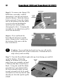
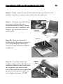
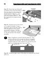
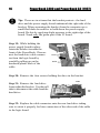
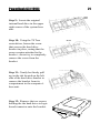
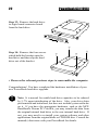
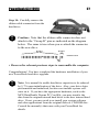
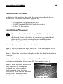
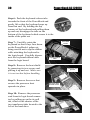
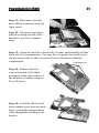
Internal Hard Drive
Upgrade
with Installation Kit
for PowerBooks
Installation Guide
http://www.mcetech.com
CONTENTS
Introduction .................................................................................... 3
Warranty Information ................................................................... 4
PowerBook 1400 Installation ..................................................... 6
PowerBook 3400 and PowerBook G3 (1997) Installation ..... 10
PowerBook G3 (1998) Installation .......................................... 18
PowerBook G3 (1999) Installation .......................................... 23
PowerBook G3 (2000) Installation .......................................... 28
Troubleshooting .............................................................................. 33
In order to install this hard drive upgrade into a PowerBook 5300, 190, or Duo 2300 that already
has an internal IDE hard drive, a separate mounting bracket is required. You may find further
information about this bracket [MCE part number BRKT5323] at http://www.mcetech.com.
Given the very small and compact design of both the PowerBook 2400 and the iBook, these
computers are comprised of an extremely complicated set of parts, boards, and ribbon cables. The
installation of any hardware upgrade into these systems should not be attempted by anyone other
than a very qualified PowerBook technician. This being the case, MCE has not included installation
procedures for these devices in this installation guide. For further information on these procedures
or for information on iBook hard drive upgrade services, you may visit http://www.mcetech.com.
Installation Guide
3
Introduction
Thank you for purchasing a new MCE hard drive upgrade solution
for your PowerBook! We’re sure that your new high-capacity hard
drive will enrich your PowerBook computing experience.
MCE strongly recommends that the installation of the hard drive
upgrade be performed by a qualified technician. The installation
procedure involves disassembling the system and exposing its
sensitive electronics. This is a delicate process and, if not performed properly, could cause damage to the computer. MCE
cannot be held liable for damage done to the computer, the person
installing the drive, or to the drive itself. These installation instructions are given for those who understand these risks. If
performed correctly, these instructions will guide an individual
step-by-step through a successful installation of the new MCE
product.
If any difficulty is encountered during the installation of the hard
drive, you may receive technical assistance by calling (949)4580800 or by sending an email to [email protected].
4
Installation Guide
Warranty Information
This is your Mac Components Engineered (MCE) three year limited
warranty. The original purchaser (Purchaser) must present proof of
purchase and proof of purchase date (Bill of Sale) to obtain warranty
service.
The MCE product is warranted by Mac Components Engineered to be
free from defects in material and workmanship for three (3) years from
the date of purchase by the Purchaser.
Purchaser's sole remedy under an MCE warranty shall be, at MCE's sole
election, refund, repair or replacement as provided in this warranty. An
MCE warranty shall not apply to any failure or defect caused by misuse,
abnormal use, neglect, abuse, alteration, improper installation, unauthorized repair or modification, improper testing, accident or causes external
to the product such as but not limited to excessive heat or humidity,
power failure, or surges, or improper installation, or damage arising from
improper packaging during transport; and damage resulting from causes,
including without limitation, lack of technical skill, competence, or
experience of the user. This warranty shall not be enlarged, diminished
or affected by, and no liability shall arise out of, MCE's rendering of
technical advice or providing information to Purchaser. Service by
anyone other than MCE authorized service personnel voids any MCE
warranty. MCE makes no representations or warranties, express or
implied, regarding the fitness of a product for any particular purpose, or
that a product is compatible with any particular hardware or software.
MCE's sole and exclusive maximum liability for any claim by Purchaser
arising out of Purchaser's purchase of a product and/or the above warranty shall not in any event exceed the actual amount paid by Purchaser
for the product. In no event shall MCE be liable for any direct, indirect,
incidental, collateral, exemplary, consequential or special damages or
losses arising out of Purchaser's purchase and/or use of products, including, without limitation, loss of use, profits, goodwill or savings, or loss of
data, data files, or programs that may have been stored by a user of the
product.
MCE Hard Drive Upgrade Installation Guide
5
Continued use or possession of a product after expiration of its warranty
period shall be conclusive evidence that the warranty is fulfilled to the
full satisfaction of Purchaser.
MCE shall honor the terms of an MCE warranty as described herein,
provided that the defective product is sent in its original packaging to
MCE, together with a copy of the invoice on which the product appears,
transportation and insurance prepaid, within the warranty period, and if
the product is found by MCE to be defective within the terms of the
warranty. Prior to returning any product to MCE, Purchaser must obtain
a Return Merchandise Authorization (RMA) number from MCE. No
product shall be accepted for return, repair or replacement without an
RMA number visibly written on the outside of its original packaging or
comparable packaging affording an equal degree of protection. MCE
does not pay shipping charges for merchandise shipped back to MCE.
Prior to returning the product, Purchaser must, if possible, remove any
and all programs and data from any storage media. Replacement products and parts used to repair products may be similar new or other than
new items. Replaced products and parts shall become the property of
MCE. If any product returned by Purchaser to MCE for repair or replacement is not defective within this warranty, MCE shall so advise
Purchaser and thereafter MCE shall handle such products in accordance
with Purchaser's instructions and at Purchaser's cost, after reimbursement
to MCE by Purchaser of freight charges at then current rates, and examination and testing expenses at then current rates ($60.00 per hour as of
January 2001). Prices, terms and conditions are subject to change
without notice.
Non-defective purchases which are returned to MCE must be returned
within thirty (30) days of purchase. For non-defective purchases which
are returned or refused by the Purchaser, MCE will, at its discretion,
issue a credit or refund for the purchase price of the goods, less all
shipping charges incurred in the shipment and a restocking fee of no less
than fifteen percent (15%) of the price of the goods.
6
PowerBook 1400
Introduction to PowerBook 1400 Installation
This chapter details the procedure for installing an MCE hard drive
upgrade kit into a PowerBook 1400.
MCE strongly recommends that the installation be performed by a
qualified technician. The installation procedure involves disassembling
the PowerBook and exposing its sensitive electronics. This is a delicate
process and, if not performed properly, could cause damage to the
PowerBook. These installation instructions are given for those who
understand these risks. If performed correctly, these instructions will
guide an individual step-by-step through a successful installation of the
new hard drive.
The new hard drive comes formatted and initialized with a Macintosh
driver, but generally requires the installation of appropriate Macintosh
operating system (Mac OS) software for use in the PowerBook. You will
need a reliable Macintosh volume from which to boot the PowerBook in
order to load the necessary operating system software. Once the PowerBook is booted, the new hard drive will automatically mount onto the
PowerBook’s Desktop and is ready for software installation. If the drive
does not mount onto the Desktop, the PowerBook may prompt you to
initialize the hard drive upon startup, after which the drive should then
automatically mount onto your Desktop and be ready for software
installation.
See the PowerBook User’s Manual for operating system and other
software installation procedures.
!
Caution: Due to a bug in Apple’s ROM support for SCSI Disk
Mode, a PowerBook 1400 which has an internal IDE hard drive
larger than 4GB installed cannot be used in SCSI Disk Mode. One
can use this PowerBook with an internal drive larger than 4GBin
normal Macintosh mode. There is no workaround for reliably using such a PowerBook in SCSI Disk Mode. It is recommended
that one use an Ethernet connection to transfer files if necessary.
PowerBook 1400
Installation Checklist
In addition to the new hard drive, the following items should also be
found in this PowerBook hard drive upgrade kit:
- (1) Disposable Grounding Wrist Strap
- (1) MCE Standard/Phillips Combo Screwdriver
- (1) New PowerBook 1400 Hard Drive Bracket
Installation Procedure
!
Caution: Electro-Static Discharge (ESD) can easily damage
electronic components. Before proceeding, ensure that you are
discharged of static electricity by touching a grounded metal
object and by properly securing the provided Disposable
Grounding Wrist Strap.
Step 1: Place your PowerBook on a hard, flat surface.
Step 2: If your PowerBook is on, turn it off. If the unit appears to be
off, make sure that it is not in Sleep mode.
Step 3: Completely unplug all cables from the PowerBook and remove
any batteries and PC Card modules from it.
Step 4: Remove the speaker grill by
firmly but carefully sliding it to the
left and lifting it up.
7
8
PowerBook 1400
Step 5: To move the keyboard, grasp
the metal frame at the top of the
keyboard and gently pull the keyboard up. Without putting stress on
the keyboard cable, gently turn the
keyboard onto the top case. Do not
disconnect the keyboard cable.
Cable
Metal Frame
Step 6: Locate the hard drive
situated to the left of the case
bottom. Remove the 2 screws
securing the hard drive bracket.
Screw
Insert a flat-blade screwdriver into
Screw
the small depression indicated and
pry the shielded drive up. Swing
the drive outward so that it is
carefully sitting on the edge of the
case. You may need to gently but
Depression
firmly pull on the hard drive/
Drive
ribbon assembly to provide some
slack in the hard drive ribbon so as to allow you to maneuver the
ribbon connector, epecially when replacing it back onto the replacement hard drive.
!
Caution: Great care must be taken in this action; if the ribbon is
damaged you will need to remove the logic board in order to
replace it.
Strap
Step 7: Grasp the ribbon strap and
disconnect the ribbon from the
hard drive by carefully pulling the
ribbon straight off to prevent
damage to the pins.
Cable
PowerBook 1400
Step 8: Remove the four screws
from the shield. Pull the hard drive Bracket
out from the shield. Note: The
original hard drive may have had a
jumper on one set of connector pins.
Do not transfer this jumper to the new
hard drive.
9
Screw
Hard Drive
Step 9: Install the new shield with the
appropriate screw holes which came in
the installation kit onto the new hard drive.
Step 10: With its shield side up, place the hard drive on the edge of the
top case. Connect the hard drive ribbon to the drive, making sure the pins
go in straight. After connecting the ribbon, fold the drive/ribbon assembly over. Fold the ribbon into its space and then firmly push the small lip
of the shield into the groove on the top case. Screw the shield in place.
Replace the keyboard and speaker grill.
Congratulations! You have completed the hardware installation of your
PowerBook hard drive upgrade.
!
Note: It is normal for usable hard drive capacities to be reduced
by 5-7% upon initialization of the drive. Also, your drive ships
preformatted and initialized, but does not include system software on it. If you have the appropriate hardware, such as the
MCE DataShuttle Xtreme PC Card Kit, you may transfer the
data from the original internal hard drive to the new internal hard
drive. If not, you may need to re-install your system software
and other applications from the original disks or CD-ROM disc.
Consult the manual(s) that came with your PowerBook for
details.
10
PowerBook 3400 and PowerBook G3 (1997)
Introduction to PowerBook 3400/G3 Installation
This chapter details the procedure for installing an MCE hard drive
upgrade kit into a PowerBook 3400 or the original PowerBook G3 (1997
release; a.k.a. Kanga).
!
Note: This section pertains to the PowerBook 3400 and PowerBook G3 model that have a multi-colored Apple logo both on the
outside of the top cover and below the display.
MCE strongly recommends that the installation be performed by a
qualified technician. The installation procedure involves disassembling
the PowerBook and exposing its sensitive electronics. This is a delicate
process and, if not performed properly, could cause damage to the
PowerBook. These installation instructions are given for those who
understand these risks. If performed correctly, these instructions will
guide an individual step-by-step through a successful installation of the
new hard drive.
The new hard drive comes formatted and initialized with a Macintosh
driver, but generally requires the installation of appropriate Macintosh
operating system (Mac OS) software for use in the PowerBook. You will
need a reliable Macintosh volume from which to boot the PowerBook in
order to load the necessary operating system software. Once the PowerBook is booted, the new hard drive will automatically mount onto the
PowerBook’s Desktop and is ready for software installation. If the drive
does not mount onto the Desktop, the PowerBook may prompt you to
initialize the hard drive upon startup, after which the drive should then
automatically mount onto your Desktop and be ready for software
installation.
See the PowerBook User’s Manual for operating system and other
software installation procedures.
!
Caution: Due to a bug in Apple’s ROM support for SCSI Disk
Mode, a PowerBook 3400/G3 which has an internal IDE hard drive
PowerBook 3400 and PowerBook G3 (1997)
11
larger than 4GB installed cannot be used in SCSI Disk Mode. One
can use this PowerBook with an internal drive larger than 4GBin
normal Macintosh mode. There is no workaround for reliably using such a PowerBook in SCSI Disk Mode. It is recommended
that one use an Ethernet connection to transfer files if necessary.
Installation Checklist
In addition to the new hard drive, the following items should also be
found in this PowerBook hard drive upgrade kit:
- (1) Disposable Grounding Wrist Strap
- (1) MCE Standard/Phillips Combo Screwdriver
- (1) Torx T8 Screwdriver
Installation Procedure
!
Caution: Electro-Static Discharge (ESD) can easily damage
electronic components. Before proceeding, ensure that you are
discharged of static electricity by touching a grounded metal
object and by properly securing the provided Disposable
Grounding Wrist Strap.
Step 1: Place your PowerBook on a hard, flat surface.
Step 2: If your PowerBook is on, turn it off. If the unit appears to be
off, make sure that it is not in Sleep mode.
Step 3: Completely unplug all cables from the PowerBook and remove
any PC Card modules from it.
Step 4: Remove the battery by
pushing the latch button in and
sliding the latch to the side. Pull the
battery completely out of the PowerBook.
Latch
Battery
12
PowerBook 3400 and PowerBook G3 (1997)
(Rear View)
Step 5: To remove the floppy/CDROM drive assembly without
damaging it, turn the unit upside
down as shown. Slide the release
button outward. Grasp the ridged
area of the plastics (not the metal
cover) to prevent bending the
metal top case and possibly
damaging the drive. Grasping the
assembly by its ridged area, pull it
out of the media bay.
Step 6: Close and latch the
PowerBook and turn it upside
down. Remove the 3 screws on
the bottom of the case with the
torx screwdriver.
!
Floppy
Drive
Assembly
Ridged Area
Release Button
Screw
Screw
Caution: If you pull the keyboard too far you will rip the
keyboard cables out of their connectors. Perform the next
steps slowly and carefully.
Step 7: Turn the PowerBook right-side-up, front facing you and lift
open the display. Rotate the
Speaker
display as far back as it will go
Grill
away from you, probably, around
170° from the base of the PowerBook. Using the small flat-blade
screwdriver to get underneath it,
lift the keyboard slightly up and
toward you until you feel a small
resistance (its four top interior tabs
should just clear the speaker grill).
STOP!
Screw
PowerBook 3400 and PowerBook G3 (1997)
Step 8: Gently rotate the top of the keyboard (the end closest to the
display) toward you, laying it face down onto the palm rest.
Step 9: Using the small flat-blade
screwdriver, detach the two
keyboard cables by gently lifting
up their respective connector ears.
Remove the keyboard, and set it
safely aside.
Keyboard Cable
Connectors
Keyboard
Turned Over
RAM Card
Step 10: If present, grasp the
RAM card by the corners closest to
you (supporting the bottom left
corner over the connector and lift
straight up.
Step 11: Carefully detach the
brightness & speaker cable from its
connector. Remove the screw from
the brightness and speaker grill.
Lift off the grill (the piece under the
up arrow in the picture) until you
feel a slight resistance. STOP!
Brightnes
& Speaker
Grill
Screw
13
14
PowerBook 3400 and PowerBook G3 (1997)
Step 12: Rotate the top of the grill
toward the front of the PowerBook.
Use your fingers to disconnect the
backup battery connector. (The
backup battery is adhered to the
grill with reusable adhesive. This
does not need to be removed from
the grill.)
Backup Battery
Connector
Backup
Battery
Step 13: Grasp the area of the clutch
cover under the display. Using a
fingernail, pull up from the seam in Clutch
Cover
back and gently rock the clutch
cover until it releases. Pull the
clutch cover straight up, watching
to clear the bottom of the display
assembly.
!
Clutch
Cover
Note: Familiarize yourself with the palm rest. This
section will have to be rotated into the area originally
occupied by the keyboard. Be carefull not to pull the
trackpad cable out of the connector as you turn over the
palm rest. Perform the next steps carefully.
Palm Rest Tab
Latch
Step 14: Grasp the right corner of the palm rest and gently but firmly
pull it up.
PowerBook 3400 and PowerBook G3 (1997)
15
Step 15: Referring to the latch noted on the previous diagram, use a
small flat-blade screwdriver to gently press the latch toward the palm rest
and at the same time rotate the top right section of the palm rest towards
the front of the PowerBook.
Step 16: Once the latch is freed, grasp the top right side of the palm rest
and pull it up slowly. Note that there are six more latches connecting the
palm rest, along the front and middle seams. Some of these latches may
be a bit tough to release, especially along the left front seam. You might
try gently rocking the palm rest to free these latches. You might also try
pushing with your thumbs on the bottom half of the case below the front
seam as you pull the top palm rest area with your other fingers.
Step 17: Rotate the palm rest
over until it is laying upside
down in the area that the keyboard originally occupied,
remembering not to pull the
trackpad cable out of the connector as you turn over the palm rest.
Step 18: Remove the three
interchangeable screws connecting the hard drive bracket to the
CPU stiffener. Lift up the
bracket until you feel a slight
resistance - STOP! Notice the hard
drive cable connecting the drive to the
logic board.
16
!
PowerBook 3400 and PowerBook G3 (1997)
Tip: There are two items that the bracket protects - the hard
drive and the power supply board underneath the right side of the
bracket. When separating the bracket from the computer use a
small flat-blade screwdriver to hold down the power supply
board. Do this by applying slight pressure to the right edge of the
board. Touch only the green part of the IC board.
Step 19: While holding the
power supply board in place
rotate the bracket towards the
front of the PowerBook. Disconnect the hard drive cable connector from the logic board by
carefully pulling up on the
hardened plastic back of the
cable.
Screw
Screw
Screw
Hard
Drive
Cable
Screw
Step 20: Remove the four screws holding the drive in the bracket.
Cable
Step 21: Remove the hard drive
from within the bracket. Use the pull
tabs to disconnect the cable from the
hard drive.
Pull
Tab
Step 22: Replace the cable connector onto the new hard drive taking
care to orient it properly for later connection of the other end of the cable
to the logic board.
PowerBook 3400 and PowerBook G3 (1997)
!
17
Caution: Note that the ribbon cable connector does not attach to
the “Group B” pins in the diagram below. The same is true when
you re-attach the connector to the new drive.
Group A
Group B
Hard Drive Pins
gap
• Reverse the relevant previous steps to reassemble the computer.
Replacement Notes
Install the palm rest before the clutch covers. The palm rest tabs fit under
the clutch cover tabs.
When replacing the keyboard screws, you may have to apply pressure to
the keyboard for the screws to engage. Apply pressure with great care.
When reinserting the floppy drive align the bay device carefully. Tolerances are tight.
As always, install the PowerBook’s battery before connecting the AC
power adapter.
Congratulations! You have completed the hardware installation of your
PowerBook hard drive upgrade.
!
Note: It is normal for usable hard drive capacities to be reduced
by 5-7% upon initialization of the drive. Also, your drive ships
preformatted and initialized, but does not include system software
on it. If you have the appropriate hardware, such as the MCE
DataShuttle Xtreme PC Card Kit, you may transfer the data from
the original internal hard drive to the new internal hard drive. If
not, you may need to re-install your system software and other
applications from the original disks or CD-ROM disc. Consult the
manual(s) that came with your PowerBook for details.
18
PowerBook G3 (1998)
Introduction to PowerBook G3 (1998) Installation
This chapter details the procedure for installing an MCE hard drive
upgrade kit into a PowerBook G3 (1998 release; a.k.a. Black keyboard
G3, Wall Street, Main Street, PDQ).
!
Note: This section pertains to the PowerBook G3 model that has a
white Apple logo on the outside of the top cover and a multi-colored Apple logo below the display.
MCE strongly recommends that the installation be performed by a
qualified technician. The installation procedure involves disassembling
the PowerBook and exposing its sensitive electronics. This is a delicate
process and, if not performed properly, could cause damage to the
PowerBook. These installation instructions are given for those who
understand these risks. If performed correctly, these instructions will
guide an individual step-by-step through a successful installation of the
new hard drive.
The new hard drive comes formatted and initialized with a Macintosh
driver, but generally requires the installation of appropriate Macintosh
operating system (Mac OS) software for use in the PowerBook. You will
need a reliable Macintosh volume from which to boot the PowerBook in
order to load the necessary operating system software. Once the PowerBook is booted, the new hard drive will automatically mount onto the
PowerBook’s Desktop and is ready for software installation. If the drive
does not mount onto the Desktop, the PowerBook may prompt you to
initialize the hard drive upon startup, after which the drive should then
automatically mount onto your Desktop and be ready for software
installation.
See the PowerBook User’s Manual for operating system and other
software installation procedures.
PowerBook G3 (1998)
19
Installation Checklist
In addition to the new hard drive, the following items should also be
found in this PowerBook hard drive upgrade kit:
- (1) Disposable Grounding Wrist Strap
- (1) MCE Standard/Phillips Combo Screwdriver
- (1) Torx T8 Screwdriver
Installation Procedure
!
Caution: Electro-Static Discharge (ESD) can easily damage
electronic components. Before proceeding, ensure that you are
discharged of static electricity by touching a grounded metal
object and by properly securing the provided Disposable
Grounding Wrist Strap.
Step 1: Place your PowerBook on a hard, flat surface.
Step 2: If your PowerBook is on, turn it off. If the unit appears to be
off, make sure that it is not in Sleep mode.
Step 3: Completely unplug all cables from the PowerBook and remove
any batteries, media bay devices, and PC Card modules from it.
Step 4: Adjust the PowerBook’s display so that it is at a 90-degree angle
to its base.
Latch
Step 5: Reach into the expansion bays with each of your index Latch
fingers and locate the plastic
keyboard release tabs on each
side. They are ridged and are
located on the underside of the
palm rest. Slide the tabs toward the front of the computer until you see
the bottom of the keyboad pop up slightly.
20
PowerBook G3 (1998)
Tabs
Step 6: Slide the keyboard
about a half inch toward the
front of the computer until the
five metal tabs on the back of
the keyboard clear the chassis.
!
Caution: Do not put tension on or remove the ribbon cables
connecting the keyboard to the logic board.
Step 7: Gently rotate the back
of the keyboard towards the front
of the system until it is resting
upside down on the palm rest.
!
Caution: If the PowerBook was just in operation, the heat sink
may be hot. If this is so, let it cool down.
Screws
Step 8: Remove the two screws
securing the internal heat sink in
place. Lift the heat sink out of
its compartment by gently but
firmly pulling up on the small
metal tab located on its front edge.
Heat Sink
Metal Tab
PowerBook G3 (1998)
21
Hard
Drive
Step 9: Locate the original
internal hard drive in the upper
right corner of the system base
unit.
Step 10: Using the T8 Torx
screwdriver, loosen the screw
that secures the hard drive
bracket in place, noting that the
screw remains attached to the
bracket - do not try to completely
remove the screw from the
bracket.
Screw
Step 11: Gently but firmly pull
up on the tab located on the left
side of the hard drive bracket to
remove the bracket from its
compartment in the computer’s
base unit.
Step 12: Remove the two screws
holding the the hard drive-to-logic
board connector onto the bracket.
Screws
22
PowerBook G3 (1998)
Step 13: Remove the hard driveto-logic board connector board
from the hard drive.
Step 14: Remove the four screws
which hold the bracket onto the
hard drive and then slip the hard
drive out of the bracket.
• Reverse the relevant previous steps to reassemble the computer.
Congratulations! You have completed the hardware installation of your
new PowerBook hard drive upgrade.
!
Note: It is normal for usable hard drive capacities to be reduced
by 5-7% upon initialization of the drive. Also, your drive ships
preformatted and initialized, but does not include system software
on it. If you have the appropriate hardware, such as the MCE
DataShuttle Xtreme PC Card Kit, you may transfer the data from
the original internal hard drive to the new internal hard drive. If
not, you may need to re-install your system software and other
applications from the original disks or CD-ROM disc. Consult the
manual(s) that came with your PowerBook for details.
PowerBook G3 (1999)
23
Introduction to PowerBook G3 (1999) Installation
This chapter details the procedure for installing an MCE hard drive
upgrade kit into a PowerBook G3 (1999 release; a.k.a. Bronze,
Lombard).
!
Note: To distinguish this PowerBook G3 from other PowerBook
G3 models, note that the computer has, among its other ports, two
built-in USB ports (
) and one built-in SCSI port (
).
MCE strongly recommends that the installation be performed by a
qualified technician. The installation procedure involves disassembling
the PowerBook and exposing its sensitive electronics. This is a delicate
process and, if not performed properly, could cause damage to the
PowerBook. These installation instructions are given for those who
understand these risks. If performed correctly, these instructions will
guide an individual step-by-step through a successful installation of the
new hard drive.
The new hard drive comes formatted and initialized with a Macintosh
driver, but generally requires the installation of appropriate Macintosh
operating system (Mac OS) software for use in the PowerBook. You will
need a reliable Macintosh volume from which to boot the PowerBook in
order to load the necessary operating system software. Once the PowerBook is booted, the new hard drive will automatically mount onto the
PowerBook’s Desktop and is ready for software installation. If the drive
does not mount onto the Desktop, the PowerBook may prompt you to
initialize the hard drive upon startup, after which the drive should then
automatically mount onto your Desktop and be ready for software
installation.
See the PowerBook User’s Manual for operating system and other
software installation procedures.
24
PowerBook G3 (1999)
Installation Checklist
In addition to the new hard drive, the following items should also be
found in this PowerBook hard drive upgrade kit:
- (1) Disposable Grounding Wrist Strap
- (1) MCE Standard/Phillips Combo Screwdriver
- (1) Torx T8 Screwdriver
Installation Procedure
!
Caution: Electro-Static Discharge (ESD) can easily damage
electronic components. Before proceeding, ensure that you are
discharged of static electricity by touching a grounded metal
object and by properly securing the provided Disposable
Grounding Wrist Strap.
Step 1: Place your PowerBook on a hard, flat surface.
Step 2: If your PowerBook is on, turn it off. If the unit appears to be
off, make sure that it is not in Sleep mode.
Step 3: Adjust the PowerBook’s display so that it is at a 90-degree angle
to its base.
Step 4: Completely unplug all cables from the PowerBook and remove
any batteries, media bay devices, and PC Card modules from it.
Step 5: If the keyboard is locked,
unlock it by turning the keyboard
lock screw counter-clockwise with a
flat head screwdriver. Note that this
keyboard locking screw is captured
and should not be removed completely from its slot.
keyboard
locking screw
PowerBook G3 (1999)
25
keyboard release tabs
Step 6: Push the keyboard
release tabs towards the front of
the PowerBook and gently lift so
that the keyboard pops up from
that end. Disengage the tabs on
the bottom of the keyboard which
secure it to the palm rest by
holding the top corners of the
keyboard and and pulling them
up and out.
Step 7: Carefully rotate the keyboard so that it lays face down on the
PowerBook’s palm rest, being careful not to pull on the ribbon cable
attaching the keyboard to the
logic board.
heatsink
screws
Step 8: Remove the heatsink by
removing its three screws and
pulling its handle up and out.
!
handle
Note: The heat spreader on the top of the processor may come
off and become attached to the bottom of the heat sink. Be sure
that the heat spreader is properly placed on the processor before
replacing the heat sink.
Step 9: Fold back the translucent
plastic flap attached to the end of
the hard drive and disconnect the
hard drive connector from the
logic board by very carefully
prying it up with the end of a
small flat blade.
26
PowerBook G3 (1999)
Step 10: Lift the plastic flap up
to bring the end of the hard drive
out of its compartment.
Step 11: Grasp the hard drive
bracket by its sides and carefully
pull the drive out of its compartment. You may have to gently but
firmly jostle the drive from side to
side to loosen it from its fasteners
within the compartment.
grommets/screws
Step 12: Remove the four
screws from out of the black
grommets at the side corners of
the hard drive bracket using the
Torx T8 driver.
Step 13: Carefully lift the hard
drive bracket away from the hard
drive, routing the orange ribbon
cable through the opening in the
bracket.
PowerBook G3 (1999)
27
Step 14: Carefully remove the
ribbon cable connector from the
hard drive.
!
Caution: Note that the ribbon cable connector does not
attach to the “Group B” pins as indicated on the diagram
below. The same is true when you re-attach the connector
to the new drive.
Group A
Group B
Hard Drive Pins
gap
• Reverse the relevant previous steps to reassemble the computer.
Congratulations! You have completed the hardware installation of your
new PowerBook hard drive upgrade.
!
Note: It is normal for usable hard drive capacities to be reduced
by 5-7% upon initialization of the drive. Also, your drive ships
preformatted and initialized, but does not include system software on it. If you have the appropriate hardware, such as the
MCE DataShuttle Xtreme PC Card Kit, you may transfer the
data from the original internal hard drive to the new internal hard
drive. If not, you may need to re-install your system software
and other applications from the original disks or CD-ROM disc.
Consult the manual(s) that came with your PowerBook for
details.
28
PowerBook G3 (2000)
Introduction to PowerBook 2000 Installation
This chapter details the procedure for installing an MCE hard drive
upgrade kit into a PowerBook G3 (2000 release; a.k.a. FireWire, Pismo).
!
Note: To distinguish this PowerBook G3 from other PowerBook
G3 models, note that this PowerBook has two built-in FireWire
ports (
).
MCE strongly recommends that the installation be performed by a
qualified technician. The installation procedure involves disassembling
the PowerBook and exposing its sensitive electronics. This is a delicate
process and, if not performed properly, could cause damage to the
PowerBook. These installation instructions are given for those who
understand these risks. If performed correctly, these instructions will
guide an individual step-by-step through a successful installation of the
new hard drive.
The new hard drive comes formatted and initialized with a Macintosh
driver, but generally requires the installation of appropriate Macintosh
operating system (Mac OS) software for use in the PowerBook. You will
need a reliable Macintosh volume from which to boot the PowerBook in
order to load the necessary operating system software. Once the PowerBook is booted, the new hard drive will automatically mount onto the
PowerBook’s Desktop and is ready for software installation. If the drive
does not mount onto the Desktop, the PowerBook may prompt you to
initialize the hard drive upon startup, after which the drive should then
automatically mount onto your Desktop and be ready for software
installation.
See the PowerBook User’s Manual for operating system and other
software installation procedures.
PowerBook G3 (2000)
29
Installation Checklist
In addition to the new hard drive, the following items should also be
found in the PowerBook hard drive upgrade kit:
- (1) Disposable Grounding Wrist Strap
- (1) MCE Standard/Phillips Combo Screwdriver
- (1) Torx T8 Screwdriver
Installation Procedure
!
Caution: Electro-Static Discharge (ESD) can easily damage
electronic components. Before proceeding, ensure that you are
discharged of static electricity by touching a grounded metal
object and by properly securing the provided Disposable
Grounding Wrist Strap.
Step 1: Place your PowerBook on a hard, flat surface.
Step 2: If your PowerBook is on, turn it off. If the unit appears to be
off, make sure that it is not in Sleep mode.
Step 3: Adjust the PowerBook’s display so that it is tilted back as far as
it will go.
Step 4: Completely unplug all cables from the PowerBook and remove
any batteries, media bay devices, and PC Card modules from it.
Step 5: If the keyboard is locked in
place, unlock it by turning the
keyboard lock screw counterclockwise with a tiny flat head
screwdriver. Note that this keyboard
locking screw is captured and
should not be removed from its slot.
keyboard lock screw
keyboard release tabs
30
PowerBook G3 (2000)
Step 6: Push the keyboard release tabs
towards the front of the PowerBook and
gently lift so that the keyboard pops up
from that end. By holding the top
corners of the keyboard and pulling them
up and out, disengage the tabs on the
bottom of the keyboard which secure it to the
inside of the palm rest .
Step 7: Carefully rotate the
keyboard so that it lays face down
on the PowerBook’s palm rest,
being careful not to rip the ribbon
cable attaching the keyboard to
the logic board. Carefully disconnect the keyboard ribbon cable
from the logic board.
heat shield
screws
keyboard ribbon
cable
Step 8: Remove the heat shield
by removing its two screws and
pulling it up and out. Make sure
it is not too hot before handling.
Step 9: Remove the screw that
secures the processor heat
spreader in place.
Step 10: Remove the processor
card from its logic board connector by pulling up on the its pull
tab, which is the shorter of the
two translucent tabs located to the
left of the hard drive.
processor card
pull tab
processor heat
spreader screw
PowerBook G3 (2000)
31
Step 11: Disconnect the hard
drive ribbon connector from the
logic board.
Step 12: Lift up the hard drive
pull tab to bring the end of the
hard drive out of its compartment.
hard drive ribbon
connector
Step 13: Grasp the hard drive bracket by its sides and carefully pull the
drive out of its compartment. You may have to gently but firmly jostle
the drive from side to side to loosen it from its fasteners within the
compartment.
grommets/screws
Step 14: Remove the four
screws from out of the black
grommets at the side corners of
the hard drive bracket using the
Torx T8 driver.
Step 15: Carefully lift the hard
drive bracket away from the hard
drive, routing the orange ribbon
cable through the opening in the
bracket.
32
PowerBook G3 (2000)
Step 16: Carefully remove the
ribbon cable connector from the
hard drive.
!
Caution: Note that the ribbon cable connector does not attach to
the “Group B” pins in the diagram on the next page. The same is
true when you re-attach the connector to the new drive.
Group A
Group B
Hard Drive Pins
gap
• Reverse the relevant previous steps to reassemble the computer.
Congratulations! You have completed the hardware installation of your
new PowerBook hard drive upgrade.
!
Note: It is normal for usable hard drive capacities to be reduced
by 5-7% upon initialization of the drive. Also, your drive ships
preformatted and initialized, but does not include system software on it. If you have the appropriate hardware, such as the
MCE DataShuttle Xtreme PC Card Kit, you may transfer the
data from the original internal hard drive to the new internal hard
drive. If not, you may need to re-install your system software
and other applications from the original disks or CD-ROM disc.
Consult the manual(s) that came with your PowerBook for
details.
Troubleshooting
33
Troubleshooting
This section offers general advice on common issues which arise during and
after the installation of an MCE PowerBook internal hard drive upgrade kit.
Also, keep in mind that MCE suggests using the latest version of Apple’s Drive
Setup utility to initialize, format and perform other hard drive functions for all
MCE hard drive upgrade kits. This utility can be found on the CD-ROM disc of
the latest release of Apple’s MacOS system software or at Apple’s web site.
PowerBook will not start.
• Make sure that power is being supplied to the PowerBook by either its
battery or its AC power adapter.
• Make sure that the battery is properly seated in its bay.
• If the battery needs recharging, plug the appropriate end of its AC adapter
into a working outlet and the other end into the PowerBook. Let the
battery charge for several minutes. The AC adapter should become warm
after several minutes of being plugged in. If it is not, make sure that it is
plugged in properly.
• If the AC adapter is plugged into a power strip or surge suppressor, make
sure that this device is turned on.
• If you have an external keyboard or mouse attached, make sure that they
are connected properly. (Note: Be sure that your PowerBook is off before
connecting or disconnecting external keyboard or mouse.)
• Reset the PowerBook’s Power Manager (ref. Apple Tech Info Library
article #14449 at http://til.info.apple.com/techinfo.nsf/artnum/n14449).
• Re-do the installation, making sure that all recently installed hardware
upgrades are securely seated and connected properly.
Disk icon with blinking question mark appears at startup.
• This generally indicates that the PowerBook cannot properly locate a
volume from which it may load System software.
• Make sure that external peripherals are connected properly and are turned
on.
• Make sure that any SCSI devices connected to the PowerBook do not
have common ID numbers.
• Start the PowerBook with extensions turned off by pressing the Shift key
on the PowerBook’s keyboard while the PowerBook is starting up. If the
34
Troubleshooting
•
•
•
•
•
PowerBook now starts up, a software conflict is causing the condition.
Determine which system components are conflicting and disable them.
“Re-bless” the System Folder of the internal hard drive by booting from
an external volume (CD-ROM, external hard drive, etc.) and double
clicking on the System suitcase of the internal hard drive’s System Folder.
Reset the PRAM by booting with the following keys depressed simultaneously: Command, Option, P, and R. After you hear the startup tone
sound three more times, release these keys.
Test and repair the internal hard drive by booting from an external volume
and running the latest version of Apple’s Drive Setup utility program,
found either on the CD-ROM of the latest release of Mac OS system
software, or from Apple’s website.
Re-do the installation, making sure that all recently installed hardware
upgrades are securely seated and connected properly.
Reinstall system software onto the internal hard drive.
A “Sad Mac” icon appears at startup.
• Make sure that external peripherals are connected properly and are turned
on.
• Make sure that you are not trying to start the PowerBook from a volume
(hard drive, CD-ROM disc, floppy disk, etc.) that does not have system
software.
• Test and repair the internal hard drive by booting from an external volume
and running the latest version of Apple’s Drive Setup utility program,
found either on the CD-ROM of the latest release of Mac OS system
software, or from Apple’s website.
• Re-do the installation, making sure that all internal parts, and especially
their connectors, are securely seated and connected properly.
• Reinstall system software onto the internal hard drive.
PowerBook does not recognize the installed hard drive.
• Determine if the hard drive is spinning (you should be able to hear the
drive first spin up during the boot process and then continue to spin while
the computer is powered on).
• If the drive is not spinning, it is likely that either the drive itself or some
other component or connector involved in the installation of the drive is
not properly connected. Inspect all hardware involved in the installation
of the drive to ensure that all connectors are secured properly.
Troubleshooting
35
• If the drive is spinning, do the following:
- Boot from either a bootable CD or a bootable external drive and launch
the most recent version of Apple’s Drive Setup utility to see if the drive
appears in the List of Drives window.
- If the drive is listed, highlight the drive in the list and select the Mount
Volumes (command-M) under the Functions menu.
- If nothing happens, highlight the drive and select the Initialize button.
- If the drive is not listed, the computer cannot properly communicate
with the drive. Check to make sure that the drive is not misaligned on
the PowerBook’s internal hard drive connector such that it receives
power, but cannot send or receive data properly.
If you have exhausted all of the troubleshooting recommendations outlined here
and still have not resolved the problem with your new hard drive, you may
receive technical assistance by calling (949)458-0800 or by sending an email to
[email protected]. Please provide the following information:
•
•
•
•
•
•
•
Your name
Invoice number
Date of the invoice
MCE part number
PowerBook model
Mac OS version number
Description of the problem, including any relevant error messages
Since technical assistance representatives do not have access to invoice information, it is necessary that you have this information with you when contacting
them.
© 2001 Mac Components Engineered
MCE and the MCE logo are trademarks of Mac Components Engineered.
Apple, the Apple logo, Mac, the MacOS logo, Macintosh, PowerBook, and Drive Setup are trademarks of Apple Computer, Inc. registered in the U.S. and other countries.
Products and company names are trademarks of their respective companies, and are mentioned for informational purposes only and constitute neither an endorsement nor a recommendation.
Every effort has been made to ensure that the information in this
manual is accurate. Mac Components Engineered is not responsible for printing or clerical errors. Information in this document is
subject to change without notice and does not represent a commitment on the part of Mac Components Engineered.
Mac Components Engineered
Irvine, California, USA
Sales: (800)500-0622; [email protected]
Technical Support: (949)458-0800; [email protected]
http://www.mcetech.com