1
B.1 WALL-MOUNTED
B.1.1 SPECIFICATIONS ......................................... B-2
B.1.1.1
B.1.1.2
Cool Only .................................................. B-2
Heat Pump ................................................ B-4
B.1.2 OUTLINES AND DIMENSIONS .................... B-6
B.1.2.1
B.1.2.2
Cool Only .................................................. B-6
Heat Pump ................................................ B-9
B.1.3 WIRING DIAGRAM ...................................... B-12
B.1.3.1
B.1.3.2
Cool Only ................................................ B-12
Heat Pump .............................................. B-15
B.1.4 REFRIGERANT SYSTEM DIAGRAM ......... B-18
B.1.4.1
B.1.4.2
Cool Only ................................................ B-18
Heat Pump .............................................. B-20
B.1.5 PERFORMANCE CURVES ......................... B-22
B.1.5.1
Cool Only/Heat Pump ............................. B-23
B.1.6 PERFORMANCE DATA ............................... B-26
B.1.6.1
B.1.6.2
Cool Only ................................................ B-26
Heat Pump .............................................. B-36
B.1.7 NOISE CRITERIA CURVES ........................ B-47
B.1.7.1
Cool Only/Heat Pump ............................. B-47
B.1.8 REMOTE CONTROLLER OPERATION ...... B-51
B.1.8.1
B.1.8.2
B.1.8.3
MSC Type ................................................ B-51
Cool Only ................................................ B-52
Heat Pump .............................................. B-53
B.1.9 TROUBLESHOOTING ................................. B-54
B.1.10 INSTALLATION PROCEDURE ................... B-57
B.1.10.1 Cool Only/Heat Pump ............................. B-57
B.1.11 MICROPROCESSOR CONTROL ................ B-70
WALLMOUNTED
B.1.11.1 MSC Series ............................................. B-70
B.1.11.2 MS Series ................................................ B-80
B.1.11.3 MSH Series ............................................. B-87
B-1
M series
WALL-MOUNTED Cool Only MSC-C07/C09/C12TV
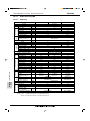
B.1.1
SPECIFICATIONS
B.1.1.1
Cool Only
WALLMOUNTED
Special remarks
SPECIFICATIONS
Fan
Compressor
motor
Electrical data
Capacity
Special
remarks
Fan
motor
Electrical data
Indoor model
Function
Indoor unit power supply
Capacity Air flow (High)
K/h
Power outlet
A
Running current
A
Power input
W
Power factor
%
Starting current
A
Fan motor current
A
Model
Winding
"
resistance (at 20:)
Dimensions WoHoD
mm
Weight
kg
Air direction
Sound level (High)
dB
Fan speed (High)
rpm
Fan speed regulator
Thermistor RT11 (at 25:) k"
Thermistor RT12 (at 25:) k"
Outdoor model
Outdoor unit power supply
Capacity
kW
Dehumidification
R/h
Outdoor air flow
K/h
Power outlet
A
Running current
A
Power input
W
Auxiliary heater
A (kW)
Power factor
%
Starting current
A
Compressor motor current
A
Fan motor current
A
Coefficient of performance (C.O.P)
Model
Output
W
Winding
"
resistance (at 20:)
Model
Winding
"
resistance (at 20:)
mm
Dimensions WoHoD
kg
Weight
Sound level
dB
Fan speed
rpm
Fan speed regulator
Refrigerant filling
kg
capacity (R407C)
Refrigerating oil (Model)
cc
MSC-C07TV
MSC-C09TV
Cooling
Single phase, 230V, 50Hz
474
10
0.17
35
90
—
0.17
RC4V19-BA
WHT-BLK 292
BLK-RED 325
850o278o191
9
5
36
950
3
10
10
MU-C07TV
MU-C09TV
Single phase, 230V, 50Hz
2.25
2.5
0.8
1.0
1,686
10
3.03
3.53
695
795
—
99
98
18
19
2.75
3.25
0.29
3.08
3.01
RE-130VGSHT
RE-145VGSHT
650
700
C-R 4.18
C-R 4.03
C-S 5.76
C-S 5.71
RA6V23-EB
WHT-BLK 258
BLK-RED 385
780o540o255
32
45
645
1
0.77
0.88
350 (NEO22 )
NOTE: Test conditions are based on JIS C 9612.
Cooling : Indoor
Dry-bulb temperature27: / Wet-bulb temperature19:
Outdoor Dry-bulb temperature35: / Wet-bulb temperature24:
B-2
MSC-C12TV
588
0.19
40
92
0.19
10
39
1,020
MU-C12TV
3.55
1.6
1,914
6.01
1,330
96
34
5.64
0.37
2.59
RE-231VHSHT
1,100
C-R 2.25
C-S 4.07
RA6V33-CB
WHT-BLK 176
BLK-RED 413
34
49
725
0.90
620 (NEO22)
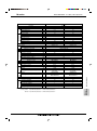
M series
WALL-MOUNTED Cool Only MS-C18/C24TV
Special remarks
Fan
motor
Compressor
Electrical
data
Capacity
Capacity
Dehumidification
Air flow (High)
Power outlet
Running current
Power input
Auxiliary heater
Power factor
Starting current
Fan motor current
Coefficient of performance (C.O.P)
Model
Winding resistance (at 20:)
Dimensions WoHoD
Weight
Air direction
Sound level (High)
Fan speed (High)
Fan speed regulator
Thermistor RT11 (at 25:)
Thermistor RT12 (at 25:)
Outdoor model
Air flow
Compressor motor current
Fan motor current
Model
Output
Winding resistance (at 20:)
MS-C18TV
kW
R/h
K/h
A
A
W
A (kW)
%
A
A
"
mm
kg
dB
rpm
k"
k"
K/h
A
A
W
"
Model
Winding resistance (at 20:)
Dimensions WoHoD
Weight
Sound level (High)
Fan speed (High)
Fan speed regulator
Refrigerant filling capacity (R407C)
Refrigerating oil (Model)
"
mm
kg
dB
rpm
kg
cc
MS-C24TV
Cooling
Single phase, 230V, 50Hz
5.1
6.4
2.4
3.1
756
816
15
25
9.3
12.7
2,100
2,840
—
98
97
50
84
0.25
0.29
2.43
2.25
RA4V27-EF
RA4V27-EE
WHT-BLK183.8 BLK-RED250.5
1,015o320o190
14
5
42
45
1,180
1,260
3
10
10
MU-C18TV
MU-C24TV
2,370
2,322
8.66
11.86
0.39
0.55
PE-33VPEHT
NE-47VMHHT
1,500
2,200
C-R1.08
C-R0.67
C-S 2.18
C-S 2.02
RA6V50-OG
RA6V60-AC
WHT-BLK116.4
WHT-BLK81.1 BLK-RED102.2
BLK-RED111.0
BLK-YLW 92.2
850o605o290
48
61
52
53
845
873
1
2
1.10
1.85
1,100 (NEO22)
1,400 (NEO22)
WALLMOUNTED
NOTE: Test conditions are based on JIS C 9612.
Cooling : Indoor
Dry-bulb temperature27: / Wet-bulb temperature19:
Outdoor Dry-bulb temperature35: / Wet-bulb temperature24:
SPECIFICATIONS
Special remarks
Fan
motor
Electrical data
Capacity
Indoor model
Function
Power supply
B-3
M series
WALL-MOUNTED Heat Pump MSC-C07/C09/C12TV
B.1.1.2
Heat Pump
WALLMOUNTED
Special remarks
SPECIFICATIONS
Fan
Compressor
motor
Electrical data
Capacity
Special
remarks
Fan
motor
Electrical data
Indoor model
Function
Indoor unit power supply
Capacity Air flow (High)
K/h
Power outlet
A
Running current
A
Power input
W
Power factor
%
Starting current
A
Fan motor current
A
Model
Winding
"
resistance (at 20:)
mm
Dimensions WoHoD
kg
Weight
Air direction
Sound level (High)
dB
Fan speed (High)
rpm
Fan speed regulator
Thermistor RT11 (at 25:) k"
Thermistor RT12 (at 25:) k"
Outdoor model
Outdoor unit power supply
Capacity
kW
Dehumidification
R/h
Outdoor air flow
K/h
Power outlet
A
Running current
A
Power input
W
Auxiliary heater
A (kW)
Power factor
%
Starting current
A
Compressor motor current
A
Fan motor current
A
Coefficient of performance (C.O.P)
Model
Output
W
Winding
"
resistance (at 20:)
Model
Winding
"
resistance (at 20:)
mm
Dimensions WoHoD
kg
Weight
Sound level
dB
Fan speed
rpm
Fan speed regulator
Refrigerant filling
kg
capacity (R407C)
Refrigerating oil (Model)
cc
Thermistor RT61 (at 0:) k"
MSC-C07TV
Cooling
Heating
MSC-C09TV
MSC-C12TV
Cooling
Heating
Cooling
Heating
Single phase, 230V, 50Hz
474
504
474
504
588
576
10
0.17
0.19
35
40
90
92
—
0.17
0.19
RC4V19-BA
WHT-BLK 292
BLK-RED 325
850o278o191
9
10
5
36
35
36
35
39
39
950
1,000
950
1,000
1,020
1,000
3
10
10
MUH-C07TV
MUH-C09TV
MUH-C12TV
Single phase, 230V, 50Hz
2.2
2.5
2.55
3.2
3.45
4.2
0.7
—
1.0
—
1.5
—
1,686
1,914
10
3.23
2.93
3.83
4.13
5.71
6.01
735
675
875
925
1,240
1,310
—
99
99
97
94
95
18
22
34
2.95
2.65
3.46
3.76
5.34
5.64
0.29
0.37
2.86
3.52
2.80
3.33
2.70
3.11
RE-135VGSHT
RE-174VGSHT
RE-231VHSHT
650
800
1,100
C-R 4.18
C-R 3.30
C-R 2.25
C-S 5.76
C-S 5.80
C-S 4.07
RA6V23-EA
RA6V33-CA
WHT-BLK 258
WHT-BLK 176
BLK-RED 385
BLK-RED 413
780o540o255
34
36
39
47
49
645
720
1
0.90
1.00
350 (NEO22)
NOTE: Test conditions are based on JIS C 9612.
Cooling : Indoor
Dry-bulb temperature27: / Wet-bulb temperature19:
Outdoor Dry-bulb temperature35: / Wet-bulb temperature24:
Heating : Indoor
Dry-bulb temperature20:
Outdoor Dry-bulb temperature 7: / Wet-bulb temperature 6:
B-4
1.25
620 (NEO22)
33.18
M series
Special remarks
Electrical
Fan
Compressor
data
motor
Capacity
Capacity
Dehumidification
Air flow (High)
Power outlet
Running current
Power input
Auxiliary heater
Power factor
Starting current
Fan motor current
Coefficient of performance (C.O.P)
Model
Winding resistance (at 20:)
Dimensions WoHoD
Weight
Air direction
Sound level (High)
Fan speed (High)
Fan speed regulator
Thermistor RT11 (at 25:)
Thermistor RT12 (at 25:)
Outdoor model
Air flow
Compressor motor current
Fan motor current
Model
Output
Winding resistance (at 20:)
kW
R/h
K/h
A
A
W
A (kW)
%
A
A
"
mm
kg
dB
rpm
k"
k"
K/h
A
A
W
"
Model
Winding resistance (at 20:)
Dimensions WoHoD
Weight
Sound level (High)
Fan speed (High)
Fan speed regulator
Refrigerant filling capacity (R407C)
Refrigerant oil (Model)
Thermistor RT61 (at 0:)
Thermistor RT63 (at 0:)
"
mm
kg
dB
rpm
kg
cc
k"
k"
MSH-C18TV
MSH-C24TV
Cooling
Heating
Cooling
Heating
Single phase, 230V, 50Hz
5.2
6.0
6.3
7.5
2.4
—
3.0
—
756
816
15
25
9.4
9.7
12.8
13.7
2,110
2,180
2,850
3,020
—
98
97
96
55
83
0.25
0.29
2.46
2.75
2.21
2.48
RA4V27-EF
RA4V27-EE
WHT-BLK183.8 BLK-RED250.5
1,015o320o190
14
5
42
45
1,180
1,260
3
10
10
MUH-C18TV
MUH-C24TV
2,196
2,700
8.76
9.06
11.93
12.87
0.39
0.58
PE-36VPEHT
NE-47VMHHT
1,600
2,200
C-R1.06
C-R0.67
C-S2.03
C-S2.02
RA6V50-OG
RA6V85-AA
WHT-BLK116.4
WHT-BLK62.7 BLK-YLW30.2
BLK-RED111.0
YLW-RED62.9
850o605o290
870o850o295
54
71
52
53
828
735
1
2
1.60
2.00
1,100 (NEO22)
1,400 (NEO22)
33.18
—
33.18
NOTE: Test conditions are based on JIS C 9612.
Cooling : Indoor
Dry-bulb temperature27: / Wet-bulb temperature 19:
Outdoor Dry-bulb temperature35: / Wet-bulb temperature (24:)
Heating : Indoor
Dry-bulb temperature20: / Wet-bulb temperature —
Outdoor Dry-bulb temperature 7: / Wet-bulb temperature 6:
B-5
WALLMOUNTED
Special remarks
Fan
motor
Electrical data
Capacity
Indoor model
Function
Power supply
SPECIFICATIONS
WALL-MOUNTED Heat Pump MSH-C18/C24TV
M series
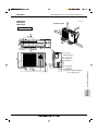
WALL-MOUNTED Cool Only MSC-C07/C09/C12TV
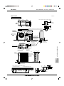
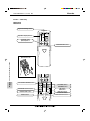
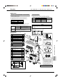
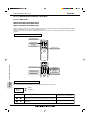
B.1.2
OUTLINES AND DIMENSIONS
B.1.2.1
Cool Only
Unit: mm
169
4.5
82
231.5
Installation plate
INDOOR UNIT
Indoor unit
271
MSC-C07TV
MSC-C09TV
81.5
326
42
2.5
41
818
116.5
326
Wall hole [65
5
850
629
58
{
100
Air in
56
165
162
Liquid line [6.35-0.5m
Gas line [9.52-0.43m
Insulation [37 O.D
[21 I.D
Drain hose [16
(Connected part O.D)
Insulation [28
67
Air out
Power supply cord
Lead to right 1.0m
Lead to left 0.3m
19
Installation plate
7 or more
278
189
78
Wireless remote controller
Installation plate
231.5
INDOOR UNIT
Indoor unit
81.5
326
42
2.5
41
818
116.5
326
Wall hole [65
850
189
56
629
165
7 or more
67
58
19
Wireless remote controller
B-6
Air out
Power supply cord
Lead to right 1.0m
Lead to left 0.3m
Installation plate
{
100
Air in
162
WALLMOUNTED
5
278
OUTLINES AND DIMENSIONS
4.5
169
271
82
MSC-C12TV
78
Liquid line [6.35-0.5m
Gas line [9.52-0.43m
Insulation [37 O.D
[21 I.D
Drain hose [16
(Connected part O.D)
Insulation [28
M series
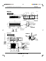
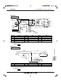
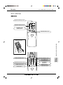
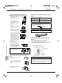
WALL-MOUNTED Cool Only MSC-C07/C09/C12TV
MU-C07TV
MU-C09TV
MU-C12TV
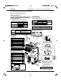
REQUIRED SPACE
OUTDOOR UNIT
100
100mm or more
Unit: mm
or m
1
Outdoor
unit
mm
ore
m
00m
or m
ore
Air in
32
320
or m
4
255
285
320
109
ore
m
00m
350
mm
Air in
Drainage
3holes [33
147
110
Air out
or
mo
re
25
Service panel
74
104
Gas refrigerant
pipe joint
Refrigerant pipe
(flared) [9.52 (MU-C07/C09TV)
[12.7 (MU-C12TV)
OUTLINES AND DIMENSIONS
40
122
500
780
WALLMOUNTED
10
155
90
260
43- 53
540
Liquid refrigerant
pipe joint
Refrigerant pipe
(flared) [6.35
B-7
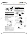
M series
WALL-MOUNTED Cool Only MS-C18/C24TV
MS-C18TV
MS-C24TV
Unit: mm
Indoor unit
4holes 11o20
INDOOR UNIT
648
217
450
297
254
60
40
20
150
995
3
450
438
352
Wall hole [75
Installation plate
1015
190
5
320
Installation plate
{
Air in
50
775
190
58
Liquid line [8-0.5m
Gas line [12-0.43m
Insulation [50 O.D
[28 I.D
Drain hose [16
Insulation [28
Air out
19
162
Power supply cord
Lead to right 2m
Lead to left 1m
Wireless remote controller
35
Drainage
hole [16.2
100
mm
100mm or more
OUTDOOR UNIT
or m
20
345
50
30
Service panel
20
183
500
850
B-8
100
157
292
30-
605
Liquid refrigerant
pipe joint
Refregerant pipe
(flared) [6.35(MU-C18TV)
[9.52(MU-C24TV)
35-
WALLMOUNTED
Air out
310
290
Air in
m
500
re
r mo
mo
Drainage
3holes [33
ore
rm
mo
m
100
ore
355
350
Air in
248
90
OUTLINES AND DIMENSIONS
MU-C18TV
MU-C24TV
161
74
Gas refregerant
pipe joint
Refregerant pipe
(flared) [15.88
350
mm
or m
ore
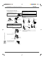
M series
Heat Pump
Unit: mm
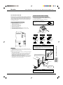
REQUIRED SPACE
MUH-C07TV
MUH-C09TV
MUH-C12TV
OUTDOOR UNIT
100
100mm or more
B.1.2.2
WALL-MOUNTED Heat Pump MSC-C07/C09/C12TV
or m
1
Outdoor
unit
mm
ore
m
00m
or m
ore
Air in
32
320
or m
4
255
285
320
109
ore
m
00m
350
mm
Air in
Drainage
3holes [33
147
110
Air out
or
mo
re
25
Service panel
74
104
Gas refrigerant
pipe joint
Refrigerant pipe
(flared) [9.52 (MUH-C07/C09TV)
[12.7 (MUH-C12TV)
OUTLINES AND DIMENSIONS
40
122
500
780
WALLMOUNTED
10
155
90
260
43- 53
540
Liquid refrigerant
pipe joint
Refrigerant pipe
(flared) [6.35
B-9
M series
WALL-MOUNTED Heat Pump MSH-C18/C24TV
MSH-C18TV
MSH-C24TV
Unit: mm
Indoor unit
4holes 11o20
INDOOR UNIT
648
217
450
297
254
60
40
20
150
995
3
450
438
352
Wall hole [75
Installation plate
1015
190
5
320
Installation plate
{
Air in
50
775
190
58
19
Liquid line [8-0.5m
Gas line [12-0.43m
Insulation [50 O.D
[28 I.D
Drain hose [16
Insulation [28
Air out
162
Power supply cord
Lead to right 2m
Lead to left 1m
Wireless remote controller
100mm or more
OUTDOOR UNIT
355
350
Air in
100
mm
20
WALLMOUNTED
Air out
345
290
Air in
Drainage
3holes [33
or m
ore
mm
500
50
30
Service panel
20
183
B-10
100
157
35-
292
30-
605
Liquid refrigerant
pipe joint
Refregerant pipe
(flared) [6.35
500
850
ore
mm
100
or m
ore
310
35
Drainage
hole [16.2
248
90
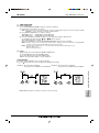
OUTLINES AND DIMENSIONS
MUH-C18TV
161
74
Gas refregerant
pipe joint
Refregerant pipe
(flared) [15.88
or m
350
mm
or m
ore
M series
WALL-MOUNTED Heat Pump MSH-C24TV
MUH-C24TV
Unit: mm
OUTDOOR UNIT
Outdoor Unit-Necessary surrounding clearance
200
39.5 27.5
330
362
Air intake
Air intake
Front opening
500
15
Air outlet
Note:Allow adequate
upper clearance
10
10
870
150
185
500
17
185
10
Terminal block for indoor and outdoor unit connection
302
Service space
500
Outlet guide
installation hole
Handle for moving
Service panel
Handle for moving
553
2-12o23 Oval holes
(standard bolt M10)
45
Knock out hole
for front piping
(refrigerant,drainage
and wiring)
60
60
120
53
450
445
524
Knock out holes for
power line 2-[27
33
45
104
42
40
Refrigerant-pipe flared
connection [15.88
Refrigerant-pipe flared
connection [9.52
179
441
468
850
524
A
Knock out hole
for right piping
(refrigerant,drainage
and wiring)
Drainage hole [33
OUTLINES AND DIMENSIONS
Bottom
piping hole
2-U-shaped
notched
holes
Drainage hole [33
7
A
295
24
Handle
for moving
Side air intake
33
R2
80
0
100
10
12
For 10 units or less
1000
Standard bolt length
17
200
R6
25 max.
Outdoor Unit-Necessary surrounding clearance
(Concentrated installation)
The upper side must be open.
0
Rear piping hole
R2
95
23
138
WALLMOUNTED
Rear fresh
air intake
65
Front right piping holesdetail figures
B-11
M series
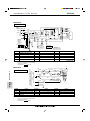
WALL-MOUNTED Cool Only MSC-C07/C09/C12TV
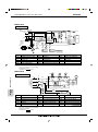
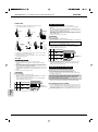
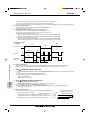
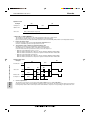
B.1.3
WIRING DIAGRAM
B.1.3.1
Cool Only
MSC-C07TV, MSC-C09TV, MSC-C12TV
INDOOR UNIT
TO OUTDOOR
TB
UNIT
L
CONNECTING
BRN
FOR
3
MUH TYPE
FOR
MU TYPE
2
BLU
BLU
WHT
1
12V
BLK
CN
151
POWER
SUPPLY
CORD
~/N 230V
50Hz
GRN/YLW
NAME
C11
INDOOR FAN CAPACITOR
F11
FUSE(3.15A)
MF
TRANS
RT12
CN
111
RT11
SR141
BLK
GRY
YLW
BRN
WHT
RED
3
CN
121
C11
F11
1
2
3
1
2
3
MF
4
5
6
CN211
LD101T
5
5
CIRCUIT BREAKER
HIC1
NR11
CN
112
ELECTRONIC CONTROL P.C. BOARD
PE
SYMBOL
HIC1
CN201
3
2
1
CN202
2
1
RED
N
12V
TAB12
BRN
POWER MONITOR,
RECEIVER
P.C.BOARD
MV
REMOTE
CONTROLLER
NAME
SYMBOL
NAME
SYMBOL
VANE MOTOR
MV
SR141
NR11
VARISTOR
DC/DC CONVERTER
RT11
ROOM TEMPERATURE THERMISTOR
INDOOR FAN MOTOR(INNER FUSE)
RT12
INDOOR COIL THERMISTOR
TB
SOLID STATE RELAY
TERMINAL BLOCK
SG79J047H01
NOTE: 1. About the outdoor side electric wiring refer to the outdoor unit electric wiring diagram for servicing.
2. Use copper conductors only. (For field wiring)
3. Symbols below indicate.
/: Terminal block,
: Connector
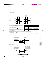
MU-C07TV, MU-C09TV, MU-C12TV
OUTDOOR UNIT
WIRING DIAGRAM
FROM
INDOOR UNIT
CONNECTING
12V
TB2
2
WHT
1
TB1
CIRCUIT BREAKER
L
WALLMOUNTED
POWER SUPPLY
~ /N
230V
50Hz
N
52C
BLK
BRN
52C
WHT
BRN
NO
DSAR
COM
C
WHT
C1
BLU
RED
S
PE
F
GRN/YLW
C2
MC
R
BLK
WHT
WHT 1 WHT
BLU 2 BLK
RED 3 RED
MF
SYMBOL
NAME
SYMBOL
C1
COMPRESSOR CAPACITOR
F
C2
OUTDOOR FAN CAPACITOR
MC
NAME
TB1,TB2 TERMINAL BLOCK
COMPRESSOR(INNER PROTECTOR)
52C
CONTACTOR
SURGE ABSORBER
MF
OUTDOOR FAN MOTOR(INNER PROTECTOR)
DSAR
NAME
SYMBOL
FUSE(2A)
NOTE: 1. About the indoor side electric wiring refer to the indoor unit electric wiring diagram for servicing.
2. Use copper conductors only. (For field wiring)
3. Symbols below indicate.
/: Terminal block,
: Connector
B-12
VG79B057H01
M series
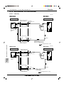
WALL-MOUNTED Cool Only MS-C18TV
MS-C18TV
INDOOR UNIT
TB
BRN
HIC1
BRN
4
CN201
3
1
1
BLU
BLU
3
TRANS
BRN
BLU
DSAR
POWER
SUPPLY
CORD
~/N 230V
50Hz
PE
52C
CN
121
CN
102
CN
151
CN
101
3
BRN
YLW
GRY
WHT MF
RED
BLK
4
2
1
F11
LD1
RT12
CN211
C11
N
230V~
BLU
2
BLU
WHT
CN
112
IC141
NR11
F12
2
GRN/YLW
L
TO OUTDOOR
UNIT
CONNECTING
CN
RT11
ELECTRONIC CONTROL P.C. BOARD 111
5
3
CIRCUIT BREAKER
3
MV
DISPLAY
RECEIVER
P.C. BOARD
P.C. BOARD
REMOTE
GRN/YLW
NAME
SYMBOL
C11
CONTROLLER
SYMBOL
INDOOR FAN CAPACITOR
IC141
NAME
SYMBOL
NAME
RT12
INDOOR COIL THERMISTOR
HYBRID IC
SURGE ABSORBER
MF
INDOOR FAN MOTOR(INNER FUSE)
TB
TERMINAL BLOCK
F11
FUSE(3.15A)
MV
VANE MOTOR
52C
CONTACTOR
F12
THERMAL FUSE(93:)
NR11
VARISTOR
HIC1
DC/DC CONVERTER
RT11
ROOM TEMPERATURE THERMISTOR
DSAR
VG79B066H01
NOTE: 1. About the outdoor side electric wiring refer to the outdoor unit electric wiring diagram for servicing.
2. Use copper conductors only.(For field wiring)
3. Symbols below indicate.
/: Terminal block,
: Connector
MU-C18TV
WIRING DIAGRAM
OUTDOOR UNIT
TB
WHT
C
WHT
C1
BLU
N
RED
S
MC
R
F
BLK
WALLMOUNTED
230V~
FROM
INDOOR UNIT
CONNECTING
2
GRN/YLW
C2
RED
ORN
WHT
BLU
SYMBOL
NAME
C1
COMPRESSOR CAPACITOR
F
C2
OUTDOOR FAN CAPACITOR
MC
1
2
3
4
RED
ORN
WHT
MF
BLK
SYMBOL
NAME
FUSE(2A)
MF
OUTDOOR FAN MOTOR(INNER PROTECTOR)
COMPRESSOR(INNER PROTECTOR)
TB
TERMINAL BLOCK
SYMBOL
NAME
NOTE: 1. About the indoor side electric wiring refer to the indoor unit electric wiring diagram for servicing.
2. Use copper conductors only.(For field wiring)
3. Symbols below indicate.
/: Terminal block,
: Connector
SG79B965H01
B-13
M series
WALL-MOUNTED Cool Only MS-C24TV
MS-C24TV
INDOOR UNIT
TO OUTDOOR
UNIT
CONNECTING
3
TB
HIC1
RED
IC141
N
F12
BLU
BLU
2
BLU 1
BLU
2
L
F11
DSAR
GRN/YLW
RT11
3
BRN
YLW
GRY
WHT
RED
BLK
CN
101 ELECTRONIC CONTROL P.C. BOARD
3
MV
DISPLAY
P.C. BOARD
NAME
RECEIVER
P.C. BOARD
SYMBOL
INDOOR FAN CAPACITOR
REMOTE
CONTROLLER
NAME
IC141
SYMBOL
NAME
RT12
INDOOR COIL THERMISTOR
HYBRID IC
SURGE ABSORBER
MF
INDOOR FAN MOTOR(INNER FUSE)
TB
TERMINAL BLOCK
FUSE(3.15A)
MV
VANE MOTOR
52C
CONTACTOR
F12
THERMINAL FUSE(93:)
NR11
VARISTOR
HIC1
DC/DC CONVERTER
RT11
ROOM TEMPERATURE THERMISTOR
VG79B067H01
NOTE: 1. About the outdoor side electric wiring refer to the outdoor unit electric wiring diagram for servicing.
2. Use copper conductors only.(For field wiring)
3. Symbols below indicate.
/: Terminal block,
: Connector
C2
X1 3
RED
5
GRY
CR
RED
RED 7
26F1
C1
RED S
MC
BLK
WHT
52C
2
1
1
6 5 4 3 2 1
BLU
BLU
2
X1
8
BLU
6
YLW
BLK
WHT
ORN
RED
N
52C
A1/a
BL
U
A2/b
W
230V~
WIRING DIAGRAM
WALLMOUNTED
NAME
TB2
1
RED
YLW
BLK
WHT
ORN
RED
F
RED
HT
TB
3
230V~
OUTDOOR UNIT
FROM INDOOR UNIT CONNECTING
MU-C24TV
SYMBOL
MF
5
3
CIRCUIT BREAKER
GRN/YLW
C11
CN
151
LD1 CN
102
POWER
SUPPLY
CORD
~ /N 230V
50Hz
PE
CN
111
CN211
4
2
1
F11
WHT
RT12
CN
121
TRANS
WHT 1
DSAR
52C
3
WHT
BRN
SYMBOL
4
C11
230V~
CN201
3
BLU
1
NR11
230V~
CN
112
C
MF
WHT R
GRN/YLW
SYMBOL
NAME
SYMBOL
NAME
CR
CR SURGE ABSORBER
MC
COMPRESSOR (INNER PROTECTOR)
X1
C1
COMPRESSOR CAPACITOR
MF
OUTDOOR FAN MOTOR(INNER PROTECTOR)
26F1
THERMOSTAT(AIR FLOW CONTROL)
C2
OUTDOOR FAN CAPACITOR
TB
TERMINAL BLOCK
52C
COMPRESSOR CONTACTOR
FUSE(2A)
TB2
TERMINAL BLOCK
F
NOTE: 1. About the indoor side electric wiring refer to the indoor unit electric wiring diagram for servicing.
2. Use copper conductors only.(For field wiring)
3. Symbols below indicate.
/: Terminal block,
: Connector
B-14
FAN MOTOR RELAY
SG79B964H01
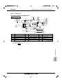
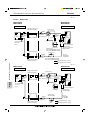
M series
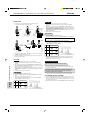
B.1.3.2
WALL-MOUNTED Heat Pump MSH-C07/C09/C12TV
Heat Pump
MUH-C07TV, MUH-C09TV, MUH-C12TV
21S4
RED
N
BLK
N
MF
CN721
CN661
X62
NR61
IC881
F61
BRN
1
SR61
BRN
DSAR
CIRCUIT BREAKER TB1
L
POWER SUPPLY
~ /N
230V
50Hz
3
2
1
C65
BLU
52C
GRN/YLW
3
C1
BLU
BLK
X62
PE
4
WHT
3
4
CN711
TRANS
TAB20
2
RED
DEICER P.C. BOARD
WHT
RED
S
BLK
C
MC
R
SYMBOL
NAME
SYMBOL
C1
COMPRESSOR CAPACITOR
MC
COMPRESSOR(INNER PROTECTOR) TB1,TB2 TERMINAL BLOCK
C65
OUTDOOR FAN CAPACITOR
MF
DSAR
F61
IC881
NAME
SYMBOL
NAME
OUTDOOR FAN MOTOR(INNER PROTECTOR)
X62
R.V. COIL RELAY
NR61
VARISTOR
21S4
R.V. COIL
FUSE(2A)
RT61
DEFROST THERMISTOR
52C
CONTACTOR
DC/DC CONVERTER
SR61
SOLID STATE RELAY
SURGE ABSORBER
NOTE: 1. About the indoor side electric wiring refer to the indoor unit electric wiring diagram for servicing.
2. Use copper conductors only. (For field wiring)
3. Symbols below indicate.
/: Terminal block,
: Connector
VG79B058H01
WIRING DIAGRAM
TB2
3
FROM
INDOOR UNIT
CONNECTING
12V
CN730
BLK
BLK
RT61
WALLMOUNTED
OUTDOOR UNIT
B-15
M series
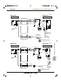
WALL-MOUNTED Heat Pump MSH-C18TV
MSH-C18TV
INDOOR UNIT
TO OUTDOOR
L TB BRN
UNIT
CONNECTING
BRN
12V
3
230V~ 2
4
BLU
BLU
F12
WHT
BLU
BLU
2
1
CN201
3
1
BLU
3
52C
TRANS
POWER SUPPLY
CORD
~/N 230V
50Hz
NAME
CN
101
BRN
YLW
GRY
WHT
RED
BLK
4
2
1
CN
ELECTRONIC CONTROL P.C. BOARD 111
RT11
3
MV
DISPLAY
RECEIVER
P.C. BOARD
P.C. BOARD
SYMBOL
INDOOR FAN CAPACITOR
IC141
REMOTE
CONTROLLER
SYMBOL
NAME
RT12
HYBRID IC
NAME
INDOOR COIL THERMISTOR
SURGE ABSORBER
MF
INDOOR FAN MOTOR(INNER FUSE)
TB
TERMINAL BLOCK
F11
FUSE(3.15A)
MV
VANE MOTOR
52C
CONTACTOR
F12
THERMAL FUSE(93:)
NR11
VARISTOR
HIC1
DC/DC CONVERTER
RT11
ROOM TEMPERATURE THERMISTOR
DSAR
MF
5
3
GRN/YLW
CIRCUIT BREAKER
C11
GRN/YLW
DSAR
PE
CN
151
3
CN211
LD1
CN
102
RT12
CN
121
F11
BRN
SYMBOL
NR11
RED
CN
112
IC141
C11
N
HIC1
VG79B068H01
NOTE: 1. About the outdoor side electric wiring refer to the outdoor unit electric wiring diagram for servicing.
2. Use copper conductors only.(For field wiring)
3. Symbols below indicate.
/: Terminal block,
: Connector
MUH-C18TV
CN730
RED
1
CN661
N
VLT
VLT
X62
SR61
1
NR61
IC881
2
RED
WHT
3
4
TRANS
WHT
MF
CN720
TAB21
2
WALLMOUNTED
DSAR
230V~
BLU
CN721
F61
WHT
52C
C65
TB
3
GRN/YLW
FROM INDOOR UNIT
CONNECTING
WIRING DIAGRAM
12V
BLK
RT61
BLK
21S4
OUTDOOR UNIT
X62
TAB20
1
2
3
BLK
4
RED
ORN
WHT
BLK
CN711
DEICER P.C. BOARD
WHT
NO
52C
COM
WHT
C1
BLU
C
RED
S
MC
R
BLK
SYMBOL
NAME
SYMBOL
NAME
SYMBOL
C1
COMPRESSOR CAPACITOR
MC
COMPRESSOR(INNER PROTECTOR)
TB
TERMINAL BLOCK
C65
OUTDOOR FAN CAPACITOR
MF
DSAR
F61
IC881
OUTDOOR FAN MOTOR(INNER PROTECTOR)
X62
R.V. COIL COIL RELAY
SURGE ABSORBER
NR61
VARISTOR
21S4
R.V. COIL
FUSE(2A)
RT61
DEFROST THERMISTOR
52C
COMPRESSOR CONTACTOR
DC/DC CONVERTER
SR61
SOLID STATE RELAY
NOTE: 1. About the indoor side electric wiring refer to the indoor unit electric wiring diagram for servicing.
2. Use copper conductors only.(For field wiring)
3. Symbols below indicate.
/: Terminal block,
: Connector
B-16
NAME
SG79B966H01
M series
WALL-MOUNTED Heat Pump MSH-C24TV
MSH-C24TV
INDOOR UNIT
TO OUTDOOR
UNIT
CONNECTING
TB
RED
N
HIC1
IC141
BLU
BLU
230V~ 2
F12
WHT
CN201
3
1
BLU
2
BLU
1
L
4
52C
3
TRANS
BRN
CN
112
WHT
C11
NAME
102
DSAR
GRN/YLW
CIRCUIT BREAKER
GRN/YLW
SYMBOL
CN
151
LD1 CN
IC141
4
2
1
ELECTRONIC CONTROL P.C. BOARD
3
MV
DISPLAY
RECEIVER
P.C. BOARD
P.C. BOARD
REMOTE
CONTROLLER
NAME
SYMBOL
NAME
RT12
INDOOR COIL THERMISTOR
HYBRID IC
SURGE ABSORBER
MF
INDOOR FAN MOTOR(INNER FUSE)
TB
TERMINAL BLOCK
F11
FUSE(3.15A)
MV
VANE MOTOR
52C
CONTACTOR
F12
THERMAL FUSE(93:)
NR11
VARISTOR
HIC1
DC/DC CONVERTER
RT11
ROOM TEMPERATURE THERMISTOR
DSAR
MF
5
3
SYMBOL
INDOOR FAN CAPACITOR
CN
101
BRN
YLW
GRY
WHT
RED
BLK
CN211
WHT
1
RT11
3
CN
121
F11
POWER SUPPLY
CORD
~/N 230V
50Hz
PE
RT12
CN
111
NR11
3
C11
12V
VG79B069H01
NOTE: 1. About the outdoor side electric wiring refer to the outdoor unit electric wiring diagram for servicing.
2. Use copper conductors only.(For field wiring)
3. Symbols below indicate.
/: Terminal block,
: Connector
MUH-C24TV
MF
RT61
YLW
BLK
WHT
ORN
RED
RT63
1 2 3 CN711
CN662
SR62
SR61
X62
COM
X62
NO
X52
1
2
3
21S4
WIRING DIAGRAM
CN661
RED
ORN C2
CN721
YLW
BLK
WHT
6 5 4 3 2 1
TAB52
OUTDOOR UNIT
C1
BLU
WHT
CZ
NAME
RED
BLU
S
MC
BLK
WHT
C
R
WHT
WHT
1
SYMBOL
WALLMOUNTED
WHT
2
DSAR
230V ~
52C 2
A2
52C
A1
NAME
CZ
CZ SURGE ABSORBER
NR61
C1
COMPRESSOR CAPACITOR
RT61
C2
OUTDOOR FAN CAPACITOR
RT63
SURGE ABSORBER
SR61
SOLID STATE RELAY
F61
FUSE(3.15A)
SR62
SOLID STATE RELAY
MC
COMPRESSOR(INNER PROTECTOR)
TB
TERMINAL BLOCK
MF
OUTDOOR FAN MOTOR(INNER PROTECTOR)
T61
TRANSFORMER
DSAR
WHT
N
BLU
SYMBOL
1
3
5
RED
DEICER P.C. BOARD
3
GRN/YLW
FROM INDOOR UNIT
CONNECTING
12V
NR61
T61
CN730
X52
TB
BLU
COM
NO
F61
SYMBOL
NAME
X52
CONTACTOR
DEFROST THERMISTOR
X62
R.V. COIL RELAY
AMBIENT TEMPERATURE THERMISTOR
21S4
R.V. COIL
52C
COMPRESSOR CONTACTOR
VARISTOR
NOTE: 1. Use copper conductors only.(For field wiring)
2. Since the indoor and outdoor unit connecting wires have polarity, connect them according to the numbers(3, N, 2).
3. Symbols below indicate.
/: Terminal block,
: Connector
SG79J155H01
B-17
M series
WALL-MOUNTED Cool Only MSC-C07/C09/C12TV
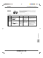
B.1.4
REFRIGERANT SYSTEM DIAGRAM
B.1.4.1
Cool Only
Unit: mm
MSC-C07TV
MSC-C09TV
MU-C07TV
MU-C09TV
INDOOR UNIT
OUTDOOR UNIT
Refrigerant pipe [9.52
Stop valve
(with heat insulator)
(with service port)
Indoor
heat
exchanger
Indoor coil
thermistor
RT12
Outdoor
heat
exchanger
Flared connection
Room temperature
thermistor
RT11
Compressor
Flared connection
Strainer
Stop valve
Capillary tube
[3.0o[1.4o600(MU-C07TV)
[3.0o[1.4o750(MU-C09TV)
Refrigerant pipe [6.35
(with heat insulator)
Refrigerant flow in cooling
REFRIGERANT SYSTEM DIAGRAM
Unit: mm
MSC-C12TV
MU-C12TV
INDOOR UNIT
Indoor
heat
exchanger
OUTDOOR UNIT
Refrigerant pipe [12.7
(with heat insulator)
Stop valve
(with service port)
Indoor coil
thermistor
RT12
Outdoor
heat
exchanger
Flared connection
WALLMOUNTED
Room temperature
thermistor
RT11
Compressor
Flared connection
Strainer
Stop valve
Refrigerant pipe [6.35
(with heat insulator)
B-18
Capillary tube
[3.0o[1.6o600
Refrigerant flow in cooling
M series
WALL-MOUNTED Cool Only MS-C18/C24TV
Unit: mm
MS-C18TV
MU-C18TV
INDOOR UNIT
OUTDOOR UNIT
Refrigerant pipe [15.88
(with heat insulator)
Indoor
heat
exchanger
Indoor coil
thermistor
RT12
Stop valve
(with service port)
Strainer
Outdoor
heat
exchanger
Distributor
Flared
connection
Room temperature
thermistor
RT11
Compressor
Capillary tube
[3.0o[2.0o850
Stop valve
Refrigerant pipe [6.35
(with heat insulator)
Refrigerant flow in cooling
Unit: mm
MU-C24TV
INDOOR UNIT
OUTDOOR UNIT
Refrigerant pipe [15.88
(with heat insulator)
Indoor coil
thermistor
RT12
Distributor
Room temperature
thermistor
RT11
Stop valve
(with service port)
Flared
connection
Outdoor
heat
exchanger
Compressor
WALLMOUNTED
Indoor
heat
exchanger
Stop valve
Refrigerant pipe [9.52
(with heat insulator)
REFRIGERANT SYSTEM DIAGRAM
MS-C24TV
Capillary tube [3.0o[2.0o550
Strainer
Refrigerant flow in cooling
B-19
M series
WALL-MOUNTED Heat Pump MSC-C07/C09/C12TV
Unit: mm
B.1.4.2
Heat Pump
MSC-C07TV
MSC-C09TV
MUH-C07TV
MUH-C09TV
INDOOR UNIT
OUTDOOR UNIT
Refrigerant pipe [9.52
(with heat insulator)
4-way valvew
Muffler
Indoor
heat
exchanger
Indoor coil
thermistor
RT12
Stop valve
(with serviceport)
Flared connection
Strainer
Defrost
thermistor
RT61
Room temperature
thermistor
RT11
Compressor
Capillary tube
[3.0o[1.6o600(MUH-C07TV)
[3.0o[1.8o400(MUH-C09TV)
Flared connection
Outdoor
heat
exchanger
Capillary tube
[3.0o[1.4o800(2 pcs)
(MUH-C07TV)
[3.0o[1.4o500(2 pcs)
(MUH-C09TV)
Check valve
Strainer
Stop valve
Refrigerant pipe [6.35
(with heat insulator)
Capillary tube
[3.0o[1.4o600(MUH-C07TV)
[3.0o[1.4o650(MUH-C09TV)
R.V. coil
heating ON
cooling OFF
Refrigerant flow in cooling
REFRIGERANT SYSTEM DIAGRAM
Refrigerant flow in heating
Unit: mm
MSC-C12TV
MUH-C12TV
INDOOR UNIT
OUTDOOR UNIT
Refrigerant pipe [12.7
(with heat insulator)
4-way valvew
Muffler
Indoor
heat
exchanger
Indoor coil
thermistor
RT12
Stop valve
(with service port)
Flared connection
Strainer
Defrost
thermistor
RT61
WALLMOUNTED
Room temperature
thermistor
RT11
Outdoor
heat
exchanger
Capillary tube
[3.0o[1.4o500(2pcs)
Compressor
Capillary tube
[3.0o[1.8o400
Flared connection
Strainer
Capillary tube
[3.0o[1.6o800
R.V. coil
heating ON
cooling OFF
Stop valve
Refrigerant pipe [6.35
(with heat insulator)
B-20
Refrigerant flow in cooling
Check
valve
Refrigerant flow in heating
M series
WALL-MOUNTED Heat Pump MSH-C18/C24TV
Unit: mm
MSH-C18TV
MUH-C18TV
INDOOR UNIT
OUTDOOR UNIT
4- way valve
Refrigerant pipe [15.88
(with heat insulator)
Indoor
heat
exchanger
Indoor coil
thermistor
RT12
Distributor
Muffler
Strainer
Stop valve
(with service port)
Defrost
thermistor
RT61
Flared connection
Outdoor
heat
exchanger
Room temperature
thermistor
RT11
Compressor
Capillary tube
[3.0o[1.4o600
(2 pcs)
Flared connection
Capillary tube
[3.0o[2.0o850
Strainer
R.V. coil
Heating ON
Cooling OFF
Stop valve
Refrigerant pipe [6.35
(with heat insulator)
Check valve
Refrigerant flow in cooling
Refrigerant flow in heating
INDOOR UNIT
OUTDOOR UNIT
Refrigerant pipe [15.88
(with heat insulator)
Indoor
heat
exchanger
Indoor coil
thermistor
RT12
Distributor
4- way valve
Muffler
Stop valve
(with service port)
Strainer
Flared connection
Room temperature
thermistor
RT11
Compressor
Outdoor
heat
exchanger
Defrost
thermistor
RT61
Flared connection
Strainer
Stop valve
Refrigerant pipe [9.52
(with heat insulator)
Receiver
Capillary tube
[3.0o[2.0o450
Ambient
temperature
thermistor
RT63
R.V. coil
Heating ON
Cooling OFF
Refrigerant flow in cooling
Refrigerant flow in heating
B-21
WALLMOUNTED
MUH-C24TV
REFRIGERANT SYSTEM DIAGRAM
Unit: mm
MSH-C24TV
M series
WALL-MOUNTED
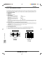
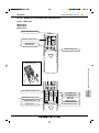
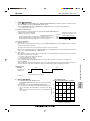
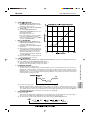
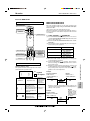
B.1.5
PERFORMANCE CURVES
The standard data contained in these specifications apply only to the operation of the air conditioner under normal conditions,
since operating conditions vary according to the areas where these units are installed. The following information has been
provided to clarify the operating characteristics of the air conditioner under the conditions indicated by the performance curve.
(1) GUARANTEED VOLTAGE
198 ~ 264V, 50Hz
(2) AIR FLOW
Air flow should be set at MAX.
(3) MAIN READINGS
(1) Indoor intake air wet-bulb temperature :
:WB
(2) Indoor outlet air wet-bulb temperature :
:WB
Cooling
(3) Outdoor intake air dry-bulb temperature :
:DB
(4) Total input:
W
(5) Indoor intake air dry-bulb temperature :
:DB
(6) Outdoor intake air wet-bulb temperature :
:WB
Heating
(7) Total input :
W
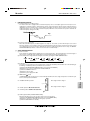
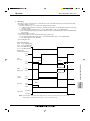
Indoor air wet/dry-bulb temperature difference on the left side of the chart on this page and next page shows the difference between the indoor intake air wet/dry-bulb temperature and the indoor outlet air wet/dry-bulb temperature for your
reference at service.
}
}
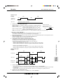
How to measure the indoor air wet-bulb/dry-bulb temperature difference
1.
2.
3.
4.
5.
6.
7.
Attach at least 2 sets of wet-and dry-bulb thermometers to the indoor air intake as shown in the figure, and at least 2 sets
of wet-and dry-bulb thermometers to the indoor air outlet. The thermometers must be attached to the position where air
speed is high.
Attach at least 2 sets of wet-and dry-bulb thermometers to the outdoor air intake.
Cover the thermometers to prevent direct rays of the sun.
Check that the air filter is cleaned.
Open windows and doors of room.
Press the EMERGENCY OPERATION switch once(twice) to start the EMERGENCY COOL(HEAT) MODE.
When system stabilizes after more than 15 minutes, measure temperature and take an average temperature.
10 minutes later, measure temperature again and check that the temperature does not change.
INDOOR UNIT
OUTDOOR UNIT
PERFORMANCE CURVES
Wet-and dry-bulb
thermometers
WALLMOUNTED
Wet-and dry-bulb
thermometers
B-22
M series
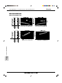
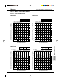
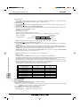
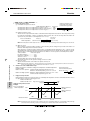
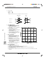
B.1.5.1
WALL-MOUNTED Cool Only/Heat Pump MSC-C07/C09/C12TV, MS-C18/C24TV
Cool Only/Heat Pump
MSC-C07TV, MU-C07TV
MSC-C09TV, MU-C09TV
MSC-C12TV, MU-C12TV
9.310.8
7.6
8.5 9.8
6.9
7.7 8.8
6.2
6.9 7.9
5.5
6.1 7.0
MSC-C12TV
(MU-C12TV)
8.4
MSC-C09TV
(MU-C09TV)
10.211.8
MSC-C07TV
(MU-C07TV)
9.1
11.2
13.5
10.1
12.2
9.1
11.0
8.2
9.8
7.2
8.6
WALLMOUNTED
MS-C24TV
14.9
MS-C18TV
12.2
PERFORMANCE CURVES
MS-C18TV, MU-C18TV
MS-C24TV, MU-C24TV
B-23
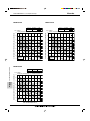
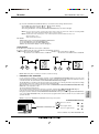
WALL-MOUNTED Cool Only/Heat Pump MSC-C07/C09/C12TV
MSC-C07TV, MUH-C07TV
MSC-C09TV, MUH-C09TV
MSC-C12TV, MUH-C12TV
9.5 10.4
7.4
8.7 9.5
6.7
7.8 8.5
6.0
7.0 7.6
5.4
6.2 6.8
19.5
24.9 28.6
18.0
23.0 26.4
16.5
21.1 24.2
15.0
19.2 22.0
13.5
17.2 19.8
13.4 15.4
9.0
11.5 13.2
MSC-C12TV
(MUH-C12TV)
15.3 17.6
10.5
MSC-C09TV
(MUH-C09TV)
12.0
MSC-C07TV
(MUH-C07TV)
PERFORMANCE CURVES
WALLMOUNTED
B-24
MSC-C12TV
(MUH-C12TV)
8.2
MSC-C09TV
(MUH-C09TV)
10.4 11.4
MSC-C07TV
(MUH-C07TV)
8.9
M series
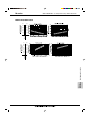
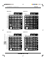
M series
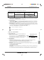
WALL-MOUNTED Cool Only/Heat Pump MSH-C18/C24TV
MSH-C18TV, MUH-C18TV
MSH-C24TV, MUH-C24TV
14.9
9.3
11.0
8.3
9.8
7.4
8.6
MSH-C24TV
13.5
12.2
31.1
36.1
28.7
33.3
26.3
30.5
24.0
27.7
21.6
25.0
19.2
22.2
16.6
MSH-C24TV
19.4
14.4
MSH-C18TV
16.8
PERFORMANCE CURVES
MSH-C18TV
11.4
10.4
WALLMOUNTED
12.5
B-25
M series
WALL-MOUNTED Cool Only MSC-C07TV
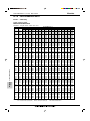
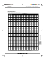
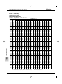
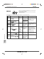
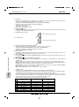
B.1.6
PERFORMANCE DATA
B.1.6.1
Cool Only
COOL operation (230V)
MSC-C07TV, MU-C07TV
CAPACITY : 2.25 kW INPUT : 730 W SHF : 0.75
PERFORMANCE DATA
WALLMOUNTED
INDOOR INDOOR
DB (:) WB (:)
21
18
21
20
22
18
22
20
22
22
23
18
23
20
23
22
24
18
24
20
24
22
24
24
25
18
25
20
25
22
25
24
26
18
26
20
26
22
26
24
26
26
27
18
27
20
27
22
27
24
27
26
28
18
28
20
28
22
28
24
28
26
29
18
29
20
29
22
29
24
29
26
30
18
30
20
30
22
30
24
30
26
31
18
31
20
31
22
31
24
31
26
32
18
32
20
32
22
32
24
32
26
NOTE:
B-26
Q
2.64
2.76
2.64
2.76
2.87
2.64
2.76
2.87
2.64
2.76
2.87
3.02
2.64
2.76
2.87
3.02
2.64
2.76
2.87
3.02
3.11
2.64
2.76
2.87
3.02
3.11
2.64
2.76
2.87
3.02
3.11
2.64
2.76
2.87
3.02
3.11
2.64
2.76
2.87
3.02
3.11
2.64
2.76
2.87
3.02
3.11
2.64
2.76
2.87
3.02
3.11
OUTDOOR DB (:)
21
25
27
30
SHC SHF INPUT Q SHC SHF INPUT Q SHC SHF INPUT Q SHC SHF INPUT
1.51 0.57 584 2.53 1.44 0.57 613 2.43 1.39 0.57 642 2.34 1.33 0.57
672
1.24 0.45 613 2.64 1.19 0.45 650 2.57 1.15 0.45 664 2.48 1.11 0.45
694
1.61 0.61 584 2.53 1.54 0.61 613 2.43 1.48 0.61 642 2.34 1.43 0.61
672
1.35 0.49 613 2.64 1.30 0.49 650 2.57 1.26 0.49 664 2.48 1.21 0.49
694
1.06 0.37 635 2.77 1.02 0.37 675 2.70 1.00 0.37 694 2.59 0.96 0.37
723
1.72 0.65 584 2.53 1.65 0.65 613 2.43 1.58 0.65 642 2.34 1.52 0.65
672
1.46 0.53 613 2.64 1.40 0.53 650 2.57 1.36 0.53 664 2.48 1.31 0.53
694
1.18 0.41 635 2.77 1.13 0.41 675 2.70 1.11 0.41 694 2.59 1.06 0.41
723
1.82 0.69 584 2.53 1.75 0.69 613 2.43 1.68 0.69 642 2.34 1.61 0.69
672
1.57 0.57 613 2.64 1.51 0.57 650 2.57 1.46 0.57 664 2.48 1.41 0.57
694
1.29 0.45 635 2.77 1.25 0.45 675 2.70 1.22 0.45 694 2.59 1.16 0.45
723
0.99 0.33 664 2.90 0.96 0.33 701 2.84 0.94 0.33 723 2.75 0.91 0.33
759
1.93 0.73 584 2.53 1.85 0.73 613 2.43 1.77 0.73 642 2.34 1.71 0.73
672
1.68 0.61 613 2.64 1.61 0.61 650 2.57 1.56 0.61 664 2.48 1.51 0.61
694
1.41 0.49 635 2.77 1.36 0.49 675 2.70 1.32 0.49 694 2.59 1.27 0.49
723
1.12 0.37 664 2.90 1.07 0.37 701 2.84 1.05 0.37 723 2.75 1.02 0.37
759
2.04 0.77 584 2.53 1.95 0.77 613 2.43 1.87 0.77 642 2.34 1.80 0.77
672
1.79 0.65 613 2.64 1.72 0.65 650 2.57 1.67 0.65 664 2.48 1.61 0.65
694
1.52 0.53 635 2.77 1.47 0.53 675 2.70 1.43 0.53 694 2.59 1.37 0.53
723
1.24 0.41 664 2.90 1.19 0.41 701 2.84 1.16 0.41 723 2.75 1.13 0.41
759
0.90 0.29 701 3.02 0.87 0.29 737 2.97 0.86 0.29 759 2.88 0.84 0.29
781
2.14 0.81 584 2.53 2.05 0.81 613 2.43 1.97 0.81 642 2.34 1.90 0.81
672
1.90 0.69 613 2.64 1.82 0.69 650 2.57 1.77 0.69 664 2.48 1.71 0.69
694
1.64 0.57 635 2.77 1.58 0.57 675 2.70 1.54 0.57 694 2.59 1.47 0.57
723
1.36 0.45 664 2.90 1.31 0.45 701 2.84 1.28 0.45 723 2.75 1.24 0.45
759
1.02 0.33 701 3.02 0.99 0.33 737 2.97 0.98 0.33 759 2.88 0.95 0.33
781
2.25 0.85 584 2.53 2.15 0.85 613 2.43 2.07 0.85 642 2.34 1.99 0.85
672
2.01 0.73 613 2.64 1.93 0.73 650 2.57 1.87 0.73 664 2.48 1.81 0.73
694
1.75 0.61 635 2.77 1.69 0.61 675 2.70 1.65 0.61 694 2.59 1.58 0.61
723
1.48 0.49 664 2.90 1.42 0.49 701 2.84 1.39 0.49 723 2.75 1.35 0.49
759
1.15 0.37 701 3.02 1.12 0.37 737 2.97 1.10 0.37 759 2.88 1.07 0.37
781
2.35 0.89 584 2.53 2.25 0.89 613 2.43 2.16 0.89 642 2.34 2.08 0.89
672
2.12 0.77 613 2.64 2.04 0.77 650 2.57 1.98 0.77 664 2.48 1.91 0.77
694
1.86 0.65 635 2.77 1.80 0.65 675 2.70 1.76 0.65 694 2.59 1.68 0.65
723
1.60 0.53 664 2.90 1.54 0.53 701 2.84 1.50 0.53 723 2.75 1.45 0.53
759
1.27 0.41 701 3.02 1.24 0.41 737 2.97 1.22 0.41 759 2.88 1.18 0.41
781
2.46 0.93 584 2.53 2.35 0.93 613 2.43 2.26 0.93 642 2.34 2.18 0.93
672
2.23 0.81 613 2.64 2.14 0.81 650 2.57 2.08 0.81 664 2.48 2.00 0.81
694
1.98 0.69 635 2.77 1.91 0.69 675 2.70 1.86 0.69 694 2.59 1.79 0.69
723
1.72 0.57 664 2.90 1.65 0.57 701 2.84 1.62 0.57 723 2.75 1.56 0.57
759
1.40 0.45 701 3.02 1.36 0.45 737 2.97 1.34 0.45 759 2.88 1.30 0.45
781
2.56 0.97 584 2.53 2.46 0.97 613 2.43 2.36 0.97 642 2.34 2.27 0.97
672
2.34 0.85 613 2.64 2.25 0.85 650 2.57 2.18 0.85 664 2.48 2.10 0.85
694
2.09 0.73 635 2.77 2.02 0.73 675 2.70 1.97 0.73 694 2.59 1.89 0.73
723
1.84 0.61 664 2.90 1.77 0.61 701 2.84 1.73 0.61 723 2.75 1.67 0.61
759
1.52 0.49 701 3.02 1.48 0.49 737 2.97 1.46 0.49 759 2.88 1.41 0.49
781
2.67 1.01 584 2.53 2.56 1.01 613 2.43 2.45 1.01 642 2.34 2.36 1.01
672
2.45 0.89 613 2.64 2.35 0.89 650 2.57 2.28 0.89 664 2.48 2.20 0.89
694
2.21 0.77 635 2.77 2.13 0.77 675 2.70 2.08 0.77 694 2.59 1.99 0.77
723
1.96 0.65 664 2.90 1.89 0.65 701 2.84 1.84 0.65 723 2.75 1.78 0.65
759
1.65 0.53 701 3.02 1.60 0.53 737 2.97 1.57 0.53 759 2.88 1.53 0.53
781
Q: Total capacity (kW)
SHC: Sensible heat capacity (kW)
SHF: Sensible heat factor
INPUT: Total power input (W)
DB: Dry-bulb temperature
WB: Wet-bulb temperature
M series
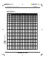
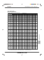
WALL-MOUNTED Cool Only MSC-C07TV
COOL operation (230V)
MSC-C07TV, MU-C07TV
NOTE:
Q
2.21
2.32
2.21
2.32
2.45
2.21
2.32
2.45
2.21
2.32
2.45
2.59
2.21
2.32
2.45
2.59
2.21
2.32
2.45
2.59
2.72
2.21
2.32
2.45
2.59
2.72
2.21
2.32
2.45
2.59
2.72
2.21
2.32
2.45
2.59
2.72
2.21
2.32
2.45
2.59
2.72
2.21
2.32
2.45
2.59
2.72
2.21
2.32
2.45
2.59
2.72
OUTDOOR DB (:)
35
40
43
46
SHC SHF INPUT Q SHC SHF INPUT Q SHC SHF INPUT Q SHC SHF INPUT
1.26 0.57 715 2.03 1.15 0.57 759 1.95 1.11 0.57 774 1.87 1.06 0.57
788
1.04 0.45 745 2.16 0.97 0.45 781 2.08 0.94 0.45 803 2.00 0.90 0.45
825
1.35 0.61 715 2.03 1.24 0.61 759 1.95 1.19 0.61 774 1.87 1.14 0.61
788
1.14 0.49 745 2.16 1.06 0.49 781 2.08 1.02 0.49 803 2.00 0.98 0.49
825
0.91 0.37 774 2.30 0.85 0.37 818 2.22 0.82 0.37 832 2.14 0.79 0.37
847
1.43 0.65 715 2.03 1.32 0.65 759 1.95 1.27 0.65 774 1.87 1.21 0.65
788
1.23 0.53 745 2.16 1.14 0.53 781 2.08 1.10 0.53 803 2.00 1.06 0.53
825
1.01 0.41 774 2.30 0.94 0.41 818 2.22 0.91 0.41 832 2.14 0.88 0.41
847
1.52 0.69 715 2.03 1.40 0.69 759 1.95 1.34 0.69 774 1.87 1.29 0.69
788
1.32 0.57 745 2.16 1.23 0.57 781 2.08 1.19 0.57 803 2.00 1.14 0.57
825
1.10 0.45 774 2.30 1.03 0.45 818 2.22 1.00 0.45 832 2.14 0.96 0.45
847
0.85 0.33 803 2.43 0.80 0.33 840 2.36 0.78 0.33 858 2.30 0.76 0.33
876
1.61 0.73 715 2.03 1.48 0.73 759 1.95 1.42 0.73 774 1.87 1.36 0.73
788
1.41 0.61 745 2.16 1.32 0.61 781 2.08 1.27 0.61 803 2.00 1.22 0.61
825
1.20 0.49 774 2.30 1.12 0.49 818 2.22 1.09 0.49 832 2.14 1.05 0.49
847
0.96 0.37 803 2.43 0.90 0.37 840 2.36 0.87 0.37 858 2.30 0.85 0.37
876
1.70 0.77 715 2.03 1.56 0.77 759 1.95 1.50 0.77 774 1.87 1.44 0.77
788
1.51 0.65 745 2.16 1.40 0.65 781 2.08 1.35 0.65 803 2.00 1.30 0.65
825
1.30 0.53 774 2.30 1.22 0.53 818 2.22 1.17 0.53 832 2.14 1.13 0.53
847
1.06 0.41 803 2.43 1.00 0.41 840 2.36 0.97 0.41 858 2.30 0.94 0.41
876
0.79 0.29 832 2.57 0.74 0.29 869 2.49 0.72 0.29 887 2.41 0.70 0.29
905
1.79 0.81 715 2.03 1.64 0.81 759 1.95 1.58 0.81 774 1.87 1.51 0.81
788
1.60 0.69 745 2.16 1.49 0.69 781 2.08 1.44 0.69 803 2.00 1.38 0.69
825
1.40 0.57 774 2.30 1.31 0.57 818 2.22 1.26 0.57 832 2.14 1.22 0.57
847
1.16 0.45 803 2.43 1.09 0.45 840 2.36 1.06 0.45 858 2.30 1.03 0.45
876
0.90 0.33 832 2.57 0.85 0.33 869 2.49 0.82 0.33 887 2.41 0.79 0.33
905
1.87 0.85 715 2.03 1.72 0.85 759 1.95 1.65 0.85 774 1.87 1.59 0.85
788
1.69 0.73 745 2.16 1.58 0.73 781 2.08 1.52 0.73 803 2.00 1.46 0.73
825
1.50 0.61 774 2.30 1.40 0.61 818 2.22 1.35 0.61 832 2.14 1.30 0.61
847
1.27 0.49 803 2.43 1.19 0.49 840 2.36 1.16 0.49 858 2.30 1.12 0.49
876
1.01 0.37 832 2.57 0.95 0.37 869 2.49 0.92 0.37 887 2.41 0.89 0.37
905
1.96 0.89 715 2.03 1.80 0.89 759 1.95 1.73 0.89 774 1.87 1.66 0.89
788
1.78 0.77 745 2.16 1.66 0.77 781 2.08 1.60 0.77 803 2.00 1.54 0.77
825
1.59 0.65 774 2.30 1.49 0.65 818 2.22 1.44 0.65 832 2.14 1.39 0.65
847
1.37 0.53 803 2.43 1.29 0.53 840 2.36 1.25 0.53 858 2.30 1.22 0.53
876
1.12 0.41 832 2.57 1.05 0.41 869 2.49 1.02 0.41 887 2.41 0.99 0.41
905
2.05 0.93 715 2.03 1.88 0.93 759 1.95 1.81 0.93 774 1.87 1.74 0.93
788
1.88 0.81 745 2.16 1.75 0.81 781 2.08 1.69 0.81 803 2.00 1.62 0.81
825
1.69 0.69 774 2.30 1.58 0.69 818 2.22 1.53 0.69 832 2.14 1.47 0.69
847
1.47 0.57 803 2.43 1.39 0.57 840 2.36 1.35 0.57 858 2.30 1.31 0.57
876
1.23 0.45 832 2.57 1.15 0.45 869 2.49 1.12 0.45 887 2.41 1.08 0.45
905
2.14 0.97 715 2.03 1.96 0.97 759 1.95 1.89 0.97 774 1.87 1.81 0.97
788
1.97 0.85 745 2.16 1.84 0.85 781 2.08 1.77 0.85 803 2.00 1.70 0.85
825
1.79 0.73 774 2.30 1.68 0.73 818 2.22 1.62 0.73 832 2.14 1.56 0.73
847
1.58 0.61 803 2.43 1.48 0.61 840 2.36 1.44 0.61 858 2.30 1.40 0.61
876
1.33 0.49 832 2.57 1.26 0.49 869 2.49 1.22 0.49 887 2.41 1.18 0.49
905
2.23 1.01 715 2.03 2.05 1.01 759 1.95 1.97 1.01 774 1.87 1.89 1.01
788
2.06 0.89 745 2.16 1.92 0.89 781 2.08 1.85 0.89 803 2.00 1.78 0.89
825
1.89 0.77 774 2.30 1.77 0.77 818 2.22 1.71 0.77 832 2.14 1.65 0.77
847
1.68 0.65 803 2.43 1.58 0.65 840 2.36 1.54 0.65 858 2.30 1.49 0.65
876
1.44 0.53 832 2.57 1.36 0.53 869 2.49 1.32 0.53 887 2.41 1.28 0.53
905
Q: Total capacity (kW)
SHC: Sensible heat capacity (kW)
SHF: Sensible heat factor
INPUT: Total power input (W)
DB: Dry-bulb temperature
WB: Wet-bulb temperature
B-27
WALLMOUNTED
INDOOR INDOOR
DB (:) WB (:)
21
18
21
20
22
18
22
20
22
22
23
18
23
20
23
22
24
18
24
20
24
22
24
24
25
18
25
20
25
22
25
24
26
18
26
20
26
22
26
24
26
26
27
18
27
20
27
22
27
24
27
26
28
18
28
20
28
22
28
24
28
26
29
18
29
20
29
22
29
24
29
26
30
18
30
20
30
22
30
24
30
26
31
18
31
20
31
22
31
24
31
26
32
18
32
20
32
22
32
24
32
26
PERFORMANCE DATA
CAPACITY : 2.25 kW INPUT : 730 W SHF : 0.75
M series
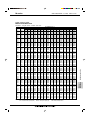
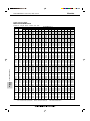
WALL-MOUNTED Cool Only MSC-C09TV
COOL operation (230V)
MSC-C09TV, MU-C09TV
CAPACITY : 2.50 kW INPUT : 830 W SHF : 0.73
PERFORMANCE DATA
WALLMOUNTED
INDOOR INDOOR
DB (:) WB (:)
21
18
21
20
22
18
22
20
22
22
23
18
23
20
23
22
24
18
24
20
24
22
24
24
25
18
25
20
25
22
25
24
26
18
26
20
26
22
26
24
26
26
27
18
27
20
27
22
27
24
27
26
28
18
28
20
28
22
28
24
28
26
29
18
29
20
29
22
29
24
29
26
30
18
30
20
30
22
30
24
30
26
31
18
31
20
31
22
31
24
31
26
32
18
32
20
32
22
32
24
32
26
NOTE:
B-28
Q
2.94
3.06
2.94
3.06
3.19
2.94
3.06
3.19
2.94
3.06
3.19
3.35
2.94
3.06
3.19
3.35
2.94
3.06
3.19
3.35
3.45
2.94
3.06
3.19
3.35
3.45
2.94
3.06
3.19
3.35
3.45
2.94
3.06
3.19
3.35
3.45
2.94
3.06
3.19
3.35
3.45
2.94
3.06
3.19
3.35
3.45
2.94
3.06
3.19
3.35
3.45
OUTDOOR DB (:)
21
25
27
30
SHC SHF INPUT Q SHC SHF INPUT Q SHC SHF INPUT Q SHC SHF INPUT
1.62 0.55 664 2.81 1.55 0.55 697 2.70 1.49 0.55 730 2.60 1.43 0.55
764
1.32 0.43 697 2.94 1.26 0.43 739 2.85 1.23 0.43 755 2.75 1.18 0.43
789
1.73 0.59 664 2.81 1.66 0.59 697 2.70 1.59 0.59 730 2.60 1.53 0.59
764
1.44 0.47 697 2.94 1.38 0.47 739 2.85 1.34 0.47 755 2.75 1.29 0.47
789
1.12 0.35 722 3.08 1.08 0.35 768 3.00 1.05 0.35 789 2.88 1.01 0.35
822
1.85 0.63 664 2.81 1.77 0.63 697 2.70 1.70 0.63 730 2.60 1.64 0.63
764
1.56 0.51 697 2.94 1.50 0.51 739 2.85 1.45 0.51 755 2.75 1.40 0.51
789
1.24 0.39 722 3.08 1.20 0.39 768 3.00 1.17 0.39 789 2.88 1.12 0.39
822
1.97 0.67 664 2.81 1.88 0.67 697 2.70 1.81 0.67 730 2.60 1.74 0.67
764
1.68 0.55 697 2.94 1.62 0.55 739 2.85 1.57 0.55 755 2.75 1.51 0.55
789
1.37 0.43 722 3.08 1.32 0.43 768 3.00 1.29 0.43 789 2.88 1.24 0.43
822
1.04 0.31 755 3.23 1.00 0.31 797 3.15 0.98 0.31 822 3.05 0.95 0.31
863
2.09 0.71 664 2.81 2.00 0.71 697 2.70 1.92 0.71 730 2.60 1.85 0.71
764
1.81 0.59 697 2.94 1.73 0.59 739 2.85 1.68 0.59 755 2.75 1.62 0.59
789
1.50 0.47 722 3.08 1.45 0.47 768 3.00 1.41 0.47 789 2.88 1.35 0.47
822
1.17 0.35 755 3.23 1.13 0.35 797 3.15 1.10 0.35 822 3.05 1.07 0.35
863
2.20 0.75 664 2.81 2.11 0.75 697 2.70 2.03 0.75 730 2.60 1.95 0.75
764
1.93 0.63 697 2.94 1.85 0.63 739 2.85 1.80 0.63 755 2.75 1.73 0.63
789
1.63 0.51 722 3.08 1.57 0.51 768 3.00 1.53 0.51 789 2.88 1.47 0.51
822
1.31 0.39 755 3.23 1.26 0.39 797 3.15 1.23 0.39 822 3.05 1.19 0.39
863
0.93 0.27 797 3.35 0.90 0.27 838 3.30 0.89 0.27 863 3.20 0.86 0.27
888
2.32 0.79 664 2.81 2.22 0.79 697 2.70 2.13 0.79 730 2.60 2.05 0.79
764
2.05 0.67 697 2.94 1.97 0.67 739 2.85 1.91 0.67 755 2.75 1.84 0.67
789
1.75 0.55 722 3.08 1.69 0.55 768 3.00 1.65 0.55 789 2.88 1.58 0.55
822
1.44 0.43 755 3.23 1.39 0.43 797 3.15 1.35 0.43 822 3.05 1.31 0.43
863
1.07 0.31 797 3.35 1.04 0.31 838 3.30 1.02 0.31 863 3.20 0.99 0.31
888
2.44 0.83 664 2.81 2.33 0.83 697 2.70 2.24 0.83 730 2.60 2.16 0.83
764
2.17 0.71 697 2.94 2.09 0.71 739 2.85 2.02 0.71 755 2.75 1.95 0.71
789
1.88 0.59 722 3.08 1.81 0.59 768 3.00 1.77 0.59 789 2.88 1.70 0.59
822
1.57 0.47 755 3.23 1.52 0.47 797 3.15 1.48 0.47 822 3.05 1.43 0.47
863
1.21 0.35 797 3.35 1.17 0.35 838 3.30 1.16 0.35 863 3.20 1.12 0.35
888
2.56 0.87 664 2.81 2.45 0.87 697 2.70 2.35 0.87 730 2.60 2.26 0.87
764
2.30 0.75 697 2.94 2.20 0.75 739 2.85 2.14 0.75 755 2.75 2.06 0.75
789
2.01 0.63 722 3.08 1.94 0.63 768 3.00 1.89 0.63 789 2.88 1.81 0.63
822
1.71 0.51 755 3.23 1.64 0.51 797 3.15 1.61 0.51 822 3.05 1.56 0.51
863
1.35 0.39 797 3.35 1.31 0.39 838 3.30 1.29 0.39 863 3.20 1.25 0.39
888
2.67 0.91 664 2.81 2.56 0.91 697 2.70 2.46 0.91 730 2.60 2.37 0.91
764
2.42 0.79 697 2.94 2.32 0.79 739 2.85 2.25 0.79 755 2.75 2.17 0.79
789
2.14 0.67 722 3.08 2.06 0.67 768 3.00 2.01 0.67 789 2.88 1.93 0.67
822
1.84 0.55 755 3.23 1.77 0.55 797 3.15 1.73 0.55 822 3.05 1.68 0.55
863
1.48 0.43 797 3.35 1.44 0.43 838 3.30 1.42 0.43 863 3.20 1.38 0.43
888
2.79 0.95 664 2.81 2.67 0.95 697 2.70 2.57 0.95 730 2.60 2.47 0.95
764
2.54 0.83 697 2.94 2.44 0.83 739 2.85 2.37 0.83 755 2.75 2.28 0.83
789
2.26 0.71 722 3.08 2.18 0.71 768 3.00 2.13 0.71 789 2.88 2.04 0.71
822
1.98 0.59 755 3.23 1.90 0.59 797 3.15 1.86 0.59 822 3.05 1.80 0.59
863
1.62 0.47 797 3.35 1.57 0.47 838 3.30 1.55 0.47 863 3.20 1.50 0.47
888
2.91 0.99 664 2.81 2.78 0.99 697 2.70 2.67 0.99 730 2.60 2.57 0.99
764
2.66 0.87 697 2.94 2.56 0.87 739 2.85 2.48 0.87 755 2.75 2.39 0.87
789
2.39 0.75 722 3.08 2.31 0.75 768 3.00 2.25 0.75 789 2.88 2.16 0.75
822
2.11 0.63 755 3.23 2.03 0.63 797 3.15 1.98 0.63 822 3.05 1.92 0.63
863
1.76 0.51 797 3.35 1.71 0.51 838 3.30 1.68 0.51 863 3.20 1.63 0.51
888
Q: Total capacity (kW)
SHC: Sensible heat capacity (kW)
SHF: Sensible heat factor
INPUT: Total power input (W)
DB: Dry-bulb temperature
WB: Wet-bulb temperature
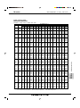
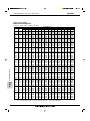
M series
WALL-MOUNTED Cool Only MSC-C09TV
COOL operation (230V)
MSC-C09TV, MU-C09TV
NOTE:
Q
2.45
2.58
2.45
2.58
2.73
2.45
2.58
2.73
2.45
2.58
2.73
2.88
2.45
2.58
2.73
2.88
2.45
2.58
2.73
2.88
3.03
2.45
2.58
2.73
2.88
3.03
2.45
2.58
2.73
2.88
3.03
2.45
2.58
2.73
2.88
3.03
2.45
2.58
2.73
2.88
3.03
2.45
2.58
2.73
2.88
3.03
2.45
2.58
2.73
2.88
3.03
OUTDOOR DB (:)
35
40
43
46
SHC SHF INPUT Q SHC SHF INPUT Q SHC SHF INPUT Q SHC SHF INPUT
1.35 0.55 813 2.25 1.24 0.55 863 2.16 1.19 0.55 880 2.08 1.14 0.55
896
1.11 0.43 847 2.40 1.03 0.43 888 2.31 0.99 0.43 913 2.23 0.96 0.43
938
1.45 0.59 813 2.25 1.33 0.59 863 2.16 1.28 0.59 880 2.08 1.22 0.59
896
1.21 0.47 847 2.40 1.13 0.47 888 2.31 1.09 0.47 913 2.23 1.05 0.47
938
0.95 0.35 880 2.55 0.89 0.35 930 2.46 0.86 0.35 946 2.38 0.83 0.35
963
1.54 0.63 813 2.25 1.42 0.63 863 2.16 1.36 0.63 880 2.08 1.31 0.63
896
1.31 0.51 847 2.40 1.22 0.51 888 2.31 1.18 0.51 913 2.23 1.13 0.51
938
1.06 0.39 880 2.55 0.99 0.39 930 2.46 0.96 0.39 946 2.38 0.93 0.39
963
1.64 0.67 813 2.25 1.51 0.67 863 2.16 1.45 0.67 880 2.08 1.39 0.67
896
1.42 0.55 847 2.40 1.32 0.55 888 2.31 1.27 0.55 913 2.23 1.22 0.55
938
1.17 0.43 880 2.55 1.10 0.43 930 2.46 1.06 0.43 946 2.38 1.02 0.43
963
0.89 0.31 913 2.70 0.84 0.31 955 2.63 0.81 0.31 975 2.55 0.79 0.31
996
1.74 0.71 813 2.25 1.60 0.71 863 2.16 1.54 0.71 880 2.08 1.47 0.71
896
1.52 0.59 847 2.40 1.42 0.59 888 2.31 1.36 0.59 913 2.23 1.31 0.59
938
1.28 0.47 880 2.55 1.20 0.47 930 2.46 1.16 0.47 946 2.38 1.12 0.47
963
1.01 0.35 913 2.70 0.95 0.35 955 2.63 0.92 0.35 975 2.55 0.89 0.35
996
1.84 0.75 813 2.25 1.69 0.75 863 2.16 1.62 0.75 880 2.08 1.56 0.75
896
1.62 0.63 847 2.40 1.51 0.63 888 2.31 1.46 0.63 913 2.23 1.40 0.63
938
1.39 0.51 880 2.55 1.30 0.51 930 2.46 1.26 0.51 946 2.38 1.21 0.51
963
1.12 0.39 913 2.70 1.05 0.39 955 2.63 1.02 0.39 975 2.55 0.99 0.39
996
0.82 0.27 946 2.85 0.77 0.27 988 2.76 0.75 0.27 1008 2.68 0.72 0.27 1029
1.94 0.79 813 2.25 1.78 0.79 863 2.16 1.71 0.79 880 2.08 1.64 0.79
896
1.73 0.67 847 2.40 1.61 0.67 888 2.31 1.55 0.67 913 2.23 1.49 0.67
938
1.50 0.55 880 2.55 1.40 0.55 930 2.46 1.35 0.55 946 2.38 1.31 0.55
963
1.24 0.43 913 2.70 1.16 0.43 955 2.63 1.13 0.43 975 2.55 1.10 0.43
996
0.94 0.31 946 2.85 0.88 0.31 988 2.76 0.86 0.31 1008 2.68 0.83 0.31 1029
2.03 0.83 813 2.25 1.87 0.83 863 2.16 1.79 0.83 880 2.08 1.72 0.83
896
1.83 0.71 847 2.40 1.70 0.71 888 2.31 1.64 0.71 913 2.23 1.58 0.71
938
1.61 0.59 880 2.55 1.50 0.59 930 2.46 1.45 0.59 946 2.38 1.40 0.59
963
1.35 0.47 913 2.70 1.27 0.47 955 2.63 1.23 0.47 975 2.55 1.20 0.47
996
1.06 0.35 946 2.85 1.00 0.35 988 2.76 0.97 0.35 1008 2.68 0.94 0.35 1029
2.13 0.87 813 2.25 1.96 0.87 863 2.16 1.88 0.87 880 2.08 1.81 0.87
896
1.93 0.75 847 2.40 1.80 0.75 888 2.31 1.73 0.75 913 2.23 1.67 0.75
938
1.72 0.63 880 2.55 1.61 0.63 930 2.46 1.55 0.63 946 2.38 1.50 0.63
963
1.47 0.51 913 2.70 1.38 0.51 955 2.63 1.34 0.51 975 2.55 1.30 0.51
996
1.18 0.39 946 2.85 1.11 0.39 988 2.76 1.08 0.39 1008 2.68 1.04 0.39 1029
2.23 0.91 813 2.25 2.05 0.91 863 2.16 1.97 0.91 880 2.08 1.89 0.91
896
2.03 0.79 847 2.40 1.90 0.79 888 2.31 1.83 0.79 913 2.23 1.76 0.79
938
1.83 0.67 880 2.55 1.71 0.67 930 2.46 1.65 0.67 946 2.38 1.59 0.67
963
1.58 0.55 913 2.70 1.49 0.55 955 2.63 1.44 0.55 975 2.55 1.40 0.55
996
1.30 0.43 946 2.85 1.23 0.43 988 2.76 1.19 0.43 1008 2.68 1.15 0.43 1029
2.33 0.95 813 2.25 2.14 0.95 863 2.16 2.05 0.95 880 2.08 1.97 0.95
896
2.14 0.83 847 2.40 1.99 0.83 888 2.31 1.92 0.83 913 2.23 1.85 0.83
938
1.93 0.71 880 2.55 1.81 0.71 930 2.46 1.75 0.71 946 2.38 1.69 0.71
963
1.70 0.59 913 2.70 1.59 0.59 955 2.63 1.55 0.59 975 2.55 1.50 0.59
996
1.42 0.47 946 2.85 1.34 0.47 988 2.76 1.30 0.47 1008 2.68 1.26 0.47 1029
2.43 0.99 813 2.25 2.23 0.99 863 2.16 2.14 0.99 880 2.08 2.05 0.99
896
2.24 0.87 847 2.40 2.09 0.87 888 2.31 2.01 0.87 913 2.23 1.94 0.87
938
2.04 0.75 880 2.55 1.91 0.75 930 2.46 1.85 0.75 946 2.38 1.78 0.75
963
1.81 0.63 913 2.70 1.70 0.63 955 2.63 1.65 0.63 975 2.55 1.61 0.63
996
1.54 0.51 946 2.85 1.45 0.51 988 2.76 1.41 0.51 1008 2.68 1.36 0.51 1029
Q: Total capacity (kW)
SHC: Sensible heat capacity (kW)
SHF: Sensible heat factor
INPUT: Total power input (W)
DB: Dry-bulb temperature
WB: Wet-bulb temperature
B-29
WALLMOUNTED
INDOOR INDOOR
DB (:) WB (:)
21
18
21
20
22
18
22
20
22
22
23
18
23
20
23
22
24
18
24
20
24
22
24
24
25
18
25
20
25
22
25
24
26
18
26
20
26
22
26
24
26
26
27
18
27
20
27
22
27
24
27
26
28
18
28
20
28
22
28
24
28
26
29
18
29
20
29
22
29
24
29
26
30
18
30
20
30
22
30
24
30
26
31
18
31
20
31
22
31
24
31
26
32
18
32
20
32
22
32
24
32
26
PERFORMANCE DATA
CAPACITY : 2.50 kW INPUT : 830 W SHF : 0.73
M series
WALL-MOUNTED Cool Only MSC-C12TV
COOL operation (230V)
MSC-C12TV, MU-C12TV
CAPACITY : 3.55 kW INPUT : 1370 W SHF : 0.69
PERFORMANCE DATA
WALLMOUNTED
INDOOR INDOOR
DB (:) WB (:)
21
18
21
20
22
18
22
20
22
22
23
18
23
20
23
22
24
18
24
20
24
22
24
24
25
18
25
20
25
22
25
24
26
18
26
20
26
22
26
24
26
26
27
18
27
20
27
22
27
24
27
26
28
18
28
20
28
22
28
24
28
26
29
18
29
20
29
22
29
24
29
26
30
18
30
20
30
22
30
24
30
26
31
18
31
20
31
22
31
24
31
26
32
18
32
20
32
22
32
24
32
26
NOTE:
B-30
Q
4.17
4.35
4.17
4.35
4.53
4.17
4.35
4.53
4.17
4.35
4.53
4.76
4.17
4.35
4.53
4.76
4.17
4.35
4.53
4.76
4.90
4.17
4.35
4.53
4.76
4.90
4.17
4.35
4.53
4.76
4.90
4.17
4.35
4.53
4.76
4.90
4.17
4.35
4.53
4.76
4.90
4.17
4.35
4.53
4.76
4.90
4.17
4.35
4.53
4.76
4.90
OUTDOOR DB (:)
21
25
27
30
SHC SHF INPUT Q SHC SHF INPUT Q SHC SHF INPUT Q SHC SHF INPUT
2.13 0.51 1096 3.99 2.04 0.51 1151 3.83 1.96 0.51 1206 3.69 1.88 0.51 1260
1.70 0.39 1151 4.17 1.63 0.39 1219 4.05 1.58 0.39 1247 3.91 1.52 0.39 1302
2.29 0.55 1096 3.99 2.20 0.55 1151 3.83 2.11 0.55 1206 3.69 2.03 0.55 1260
1.87 0.43 1151 4.17 1.79 0.43 1219 4.05 1.74 0.43 1247 3.91 1.68 0.43 1302
1.40 0.31 1192 4.37 1.35 0.31 1267 4.26 1.32 0.31 1302 4.08 1.27 0.31 1356
2.46 0.59 1096 3.99 2.36 0.59 1151 3.83 2.26 0.59 1206 3.69 2.18 0.59 1260
2.04 0.47 1151 4.17 1.96 0.47 1219 4.05 1.90 0.47 1247 3.91 1.84 0.47 1302
1.58 0.35 1192 4.37 1.53 0.35 1267 4.26 1.49 0.35 1302 4.08 1.43 0.35 1356
2.63 0.63 1096 3.99 2.52 0.63 1151 3.83 2.42 0.63 1206 3.69 2.33 0.63 1260
2.22 0.51 1151 4.17 2.13 0.51 1219 4.05 2.06 0.51 1247 3.91 1.99 0.51 1302
1.77 0.39 1192 4.37 1.70 0.39 1267 4.26 1.66 0.39 1302 4.08 1.59 0.39 1356
1.28 0.27 1247 4.58 1.24 0.27 1315 4.47 1.21 0.27 1356 4.33 1.17 0.27 1425
2.79 0.67 1096 3.99 2.68 0.67 1151 3.83 2.57 0.67 1206 3.69 2.47 0.67 1260
2.39 0.55 1151 4.17 2.29 0.55 1219 4.05 2.23 0.55 1247 3.91 2.15 0.55 1302
1.95 0.43 1192 4.37 1.88 0.43 1267 4.26 1.83 0.43 1302 4.08 1.76 0.43 1356
1.47 0.31 1247 4.58 1.42 0.31 1315 4.47 1.39 0.31 1356 4.33 1.34 0.31 1425
2.96 0.71 1096 3.99 2.84 0.71 1151 3.83 2.72 0.71 1206 3.69 2.62 0.71 1260
2.57 0.59 1151 4.17 2.46 0.59 1219 4.05 2.39 0.59 1247 3.91 2.30 0.59 1302
2.13 0.47 1192 4.37 2.05 0.47 1267 4.26 2.00 0.47 1302 4.08 1.92 0.47 1356
1.66 0.35 1247 4.58 1.60 0.35 1315 4.47 1.57 0.35 1356 4.33 1.52 0.35 1425
1.13 0.23 1315 4.76 1.09 0.23 1384 4.69 1.08 0.23 1425 4.54 1.05 0.23 1466
3.13 0.75 1096 3.99 3.00 0.75 1151 3.83 2.88 0.75 1206 3.69 2.77 0.75 1260
2.74 0.63 1151 4.17 2.63 0.63 1219 4.05 2.55 0.63 1247 3.91 2.46 0.63 1302
2.31 0.51 1192 4.37 2.23 0.51 1267 4.26 2.17 0.51 1302 4.08 2.08 0.51 1356
1.86 0.39 1247 4.58 1.79 0.39 1315 4.47 1.74 0.39 1356 4.33 1.69 0.39 1425
1.32 0.27 1315 4.76 1.28 0.27 1384 4.69 1.27 0.27 1425 4.54 1.23 0.27 1466
3.30 0.79 1096 3.99 3.16 0.79 1151 3.83 3.03 0.79 1206 3.69 2.92 0.79 1260
2.91 0.67 1151 4.17 2.79 0.67 1219 4.05 2.71 0.67 1247 3.91 2.62 0.67 1302
2.49 0.55 1192 4.37 2.40 0.55 1267 4.26 2.34 0.55 1302 4.08 2.25 0.55 1356
2.05 0.43 1247 4.58 1.97 0.43 1315 4.47 1.92 0.43 1356 4.33 1.86 0.43 1425
1.52 0.31 1315 4.76 1.47 0.31 1384 4.69 1.45 0.31 1425 4.54 1.41 0.31 1466
3.46 0.83 1096 3.99 3.31 0.83 1151 3.83 3.18 0.83 1206 3.69 3.06 0.83 1260
3.09 0.71 1151 4.17 2.96 0.71 1219 4.05 2.87 0.71 1247 3.91 2.77 0.71 1302
2.67 0.59 1192 4.37 2.58 0.59 1267 4.26 2.51 0.59 1302 4.08 2.41 0.59 1356
2.24 0.47 1247 4.58 2.15 0.47 1315 4.47 2.10 0.47 1356 4.33 2.04 0.47 1425
1.71 0.35 1315 4.76 1.66 0.35 1384 4.69 1.64 0.35 1425 4.54 1.59 0.35 1466
3.63 0.87 1096 3.99 3.47 0.87 1151 3.83 3.34 0.87 1206 3.69 3.21 0.87 1260
3.26 0.75 1151 4.17 3.13 0.75 1219 4.05 3.04 0.75 1247 3.91 2.93 0.75 1302
2.85 0.63 1192 4.37 2.75 0.63 1267 4.26 2.68 0.63 1302 4.08 2.57 0.63 1356
2.43 0.51 1247 4.58 2.34 0.51 1315 4.47 2.28 0.51 1356 4.33 2.21 0.51 1425
1.91 0.39 1315 4.76 1.86 0.39 1384 4.69 1.83 0.39 1425 4.54 1.77 0.39 1466
3.80 0.91 1096 3.99 3.63 0.91 1151 3.83 3.49 0.91 1206 3.69 3.36 0.91 1260
3.44 0.79 1151 4.17 3.30 0.79 1219 4.05 3.20 0.79 1247 3.91 3.08 0.79 1302
3.03 0.67 1192 4.37 2.93 0.67 1267 4.26 2.85 0.67 1302 4.08 2.74 0.67 1356
2.62 0.55 1247 4.58 2.52 0.55 1315 4.47 2.46 0.55 1356 4.33 2.38 0.55 1425
2.11 0.43 1315 4.76 2.05 0.43 1384 4.69 2.01 0.43 1425 4.54 1.95 0.43 1466
3.96 0.95 1096 3.99 3.79 0.95 1151 3.83 3.64 0.95 1206 3.69 3.51 0.95 1260
3.61 0.83 1151 4.17 3.46 0.83 1219 4.05 3.36 0.83 1247 3.91 3.24 0.83 1302
3.21 0.71 1192 4.37 3.10 0.71 1267 4.26 3.02 0.71 1302 4.08 2.90 0.71 1356
2.81 0.59 1247 4.58 2.70 0.59 1315 4.47 2.64 0.59 1356 4.33 2.56 0.59 1425
2.30 0.47 1315 4.76 2.24 0.47 1384 4.69 2.20 0.47 1425 4.54 2.14 0.47 1466
Q: Total capacity (kW)
SHC: Sensible heat capacity (kW)
SHF: Sensible heat factor
INPUT: Total power input (W)
DB: Dry-bulb temperature
WB: Wet-bulb temperature
M series
WALL-MOUNTED Cool Only MSC-C12TV
COOL operation (230V)
MSC-C12TV, MU-C12TV
NOTE:
Q
3.48
3.66
3.48
3.66
3.87
3.48
3.66
3.87
3.48
3.66
3.87
4.08
3.48
3.66
3.87
4.08
3.48
3.66
3.87
4.08
4.30
3.48
3.66
3.87
4.08
4.30
3.48
3.66
3.87
4.08
4.30
3.48
3.66
3.87
4.08
4.30
3.48
3.66
3.87
4.08
4.30
3.48
3.66
3.87
4.08
4.30
3.48
3.66
3.87
4.08
4.30
OUTDOOR DB (:)
35
40
43
46
SHC SHF INPUT Q SHC SHF INPUT Q SHC SHF INPUT Q SHC SHF INPUT
1.77 0.51 1343 3.20 1.63 0.51 1425 3.07 1.57 0.51 1452 2.95 1.50 0.51 1480
1.43 0.39 1397 3.41 1.33 0.39 1466 3.28 1.28 0.39 1507 3.16 1.23 0.39 1548
1.91 0.55 1343 3.20 1.76 0.55 1425 3.07 1.69 0.55 1452 2.95 1.62 0.55 1480
1.57 0.43 1397 3.41 1.47 0.43 1466 3.28 1.41 0.43 1507 3.16 1.36 0.43 1548
1.20 0.31 1452 3.62 1.12 0.31 1534 3.50 1.08 0.31 1562 3.37 1.05 0.31 1589
2.05 0.59 1343 3.20 1.89 0.59 1425 3.07 1.81 0.59 1452 2.95 1.74 0.59 1480
1.72 0.47 1397 3.41 1.60 0.47 1466 3.28 1.54 0.47 1507 3.16 1.48 0.47 1548
1.35 0.35 1452 3.62 1.27 0.35 1534 3.50 1.22 0.35 1562 3.37 1.18 0.35 1589
2.19 0.63 1343 3.20 2.01 0.63 1425 3.07 1.93 0.63 1452 2.95 1.86 0.63 1480
1.86 0.51 1397 3.41 1.74 0.51 1466 3.28 1.67 0.51 1507 3.16 1.61 0.51 1548
1.51 0.39 1452 3.62 1.41 0.39 1534 3.50 1.36 0.39 1562 3.37 1.32 0.39 1589
1.10 0.27 1507 3.83 1.04 0.27 1576 3.73 1.01 0.27 1610 3.62 0.98 0.27 1644
2.33 0.67 1343 3.20 2.14 0.67 1425 3.07 2.06 0.67 1452 2.95 1.97 0.67 1480
2.01 0.55 1397 3.41 1.87 0.55 1466 3.28 1.81 0.55 1507 3.16 1.74 0.55 1548
1.66 0.43 1452 3.62 1.56 0.43 1534 3.50 1.50 0.43 1562 3.37 1.45 0.43 1589
1.27 0.31 1507 3.83 1.19 0.31 1576 3.73 1.16 0.31 1610 3.62 1.12 0.31 1644
2.47 0.71 1343 3.20 2.27 0.71 1425 3.07 2.18 0.71 1452 2.95 2.09 0.71 1480
2.16 0.59 1397 3.41 2.01 0.59 1466 3.28 1.94 0.59 1507 3.16 1.86 0.59 1548
1.82 0.47 1452 3.62 1.70 0.47 1534 3.50 1.64 0.47 1562 3.37 1.59 0.47 1589
1.43 0.35 1507 3.83 1.34 0.35 1576 3.73 1.30 0.35 1610 3.62 1.27 0.35 1644
0.99 0.23 1562 4.05 0.93 0.23 1630 3.92 0.90 0.23 1665 3.80 0.87 0.23 1699
2.61 0.75 1343 3.20 2.40 0.75 1425 3.07 2.30 0.75 1452 2.95 2.21 0.75 1480
2.30 0.63 1397 3.41 2.15 0.63 1466 3.28 2.07 0.63 1507 3.16 1.99 0.63 1548
1.97 0.51 1452 3.62 1.85 0.51 1534 3.50 1.78 0.51 1562 3.37 1.72 0.51 1589
1.59 0.39 1507 3.83 1.50 0.39 1576 3.73 1.45 0.39 1610 3.62 1.41 0.39 1644
1.16 0.27 1562 4.05 1.09 0.27 1630 3.92 1.06 0.27 1665 3.80 1.03 0.27 1699
2.75 0.79 1343 3.20 2.52 0.79 1425 3.07 2.43 0.79 1452 2.95 2.33 0.79 1480
2.45 0.67 1397 3.41 2.28 0.67 1466 3.28 2.20 0.67 1507 3.16 2.12 0.67 1548
2.13 0.55 1452 3.62 1.99 0.55 1534 3.50 1.92 0.55 1562 3.37 1.85 0.55 1589
1.76 0.43 1507 3.83 1.65 0.43 1576 3.73 1.60 0.43 1610 3.62 1.56 0.43 1644
1.33 0.31 1562 4.05 1.25 0.31 1630 3.92 1.22 0.31 1665 3.80 1.18 0.31 1699
2.89 0.83 1343 3.20 2.65 0.83 1425 3.07 2.55 0.83 1452 2.95 2.45 0.83 1480
2.60 0.71 1397 3.41 2.42 0.71 1466 3.28 2.33 0.71 1507 3.16 2.24 0.71 1548
2.28 0.59 1452 3.62 2.14 0.59 1534 3.50 2.06 0.59 1562 3.37 1.99 0.59 1589
1.92 0.47 1507 3.83 1.80 0.47 1576 3.73 1.75 0.47 1610 3.62 1.70 0.47 1644
1.50 0.35 1562 4.05 1.42 0.35 1630 3.92 1.37 0.35 1665 3.80 1.33 0.35 1699
3.03 0.87 1343 3.20 2.78 0.87 1425 3.07 2.67 0.87 1452 2.95 2.56 0.87 1480
2.74 0.75 1397 3.41 2.56 0.75 1466 3.28 2.46 0.75 1507 3.16 2.37 0.75 1548
2.44 0.63 1452 3.62 2.28 0.63 1534 3.50 2.20 0.63 1562 3.37 2.12 0.63 1589
2.08 0.51 1507 3.83 1.96 0.51 1576 3.73 1.90 0.51 1610 3.62 1.85 0.51 1644
1.68 0.39 1562 4.05 1.58 0.39 1630 3.92 1.53 0.39 1665 3.80 1.48 0.39 1699
3.17 0.91 1343 3.20 2.91 0.91 1425 3.07 2.79 0.91 1452 2.95 2.68 0.91 1480
2.89 0.79 1397 3.41 2.69 0.79 1466 3.28 2.59 0.79 1507 3.16 2.50 0.79 1548
2.59 0.67 1452 3.62 2.43 0.67 1534 3.50 2.34 0.67 1562 3.37 2.26 0.67 1589
2.25 0.55 1507 3.83 2.11 0.55 1576 3.73 2.05 0.55 1610 3.62 1.99 0.55 1644
1.85 0.43 1562 4.05 1.74 0.43 1630 3.92 1.69 0.43 1665 3.80 1.63 0.43 1699
3.31 0.95 1343 3.20 3.04 0.95 1425 3.07 2.92 0.95 1452 2.95 2.80 0.95 1480
3.03 0.83 1397 3.41 2.83 0.83 1466 3.28 2.73 0.83 1507 3.16 2.62 0.83 1548
2.75 0.71 1452 3.62 2.57 0.71 1534 3.50 2.48 0.71 1562 3.37 2.39 0.71 1589
2.41 0.59 1507 3.83 2.26 0.59 1576 3.73 2.20 0.59 1610 3.62 2.14 0.59 1644
2.02 0.47 1562 4.05 1.90 0.47 1630 3.92 1.84 0.47 1665 3.80 1.79 0.47 1699
Q: Total capacity (kW)
SHC: Sensible heat capacity (kW)
SHF: Sensible heat factor
INPUT: Total power input (W)
DB: Dry-bulb temperature
WB: Wet-bulb temperature
B-31
WALLMOUNTED
INDOOR INDOOR
DB (:) WB (:)
21
18
21
20
22
18
22
20
22
22
23
18
23
20
23
22
24
18
24
20
24
22
24
24
25
18
25
20
25
22
25
24
26
18
26
20
26
22
26
24
26
26
27
18
27
20
27
22
27
24
27
26
28
18
28
20
28
22
28
24
28
26
29
18
29
20
29
22
29
24
29
26
30
18
30
20
30
22
30
24
30
26
31
18
31
20
31
22
31
24
31
26
32
18
32
20
32
22
32
24
32
26
PERFORMANCE DATA
CAPACITY : 3.55 kW INPUT : 1370 W SHF : 0.69
M series
WALL-MOUNTED Cool Only MS-C18TV
COOL operation (230V)
MS-C18TV, MU-C18TV
CAPACITY : 5.1 kW INPUT : 2100 W SHF : 0.71
PERFORMANCE DATA
WALLMOUNTED
INDOOR INDOOR
DB (:) WB (:)
21
18
21
20
22
18
22
20
22
22
23
18
23
20
23
22
24
18
24
20
24
22
24
24
25
18
25
20
25
22
25
24
26
18
26
20
26
22
26
24
26
26
27
18
27
20
27
22
27
24
27
26
28
18
28
20
28
22
28
24
28
26
29
18
29
20
29
22
29
24
29
26
30
18
30
20
30
22
30
24
30
26
31
18
31
20
31
22
31
24
31
26
32
18
32
20
32
22
32
24
32
26
NOTE:
B-32
Q
5.99
6.25
5.99
6.25
6.50
5.99
6.25
6.50
5.99
6.25
6.50
6.83
5.99
6.25
6.50
6.83
5.99
6.25
6.50
6.83
7.04
5.99
6.25
6.50
6.83
7.04
5.99
6.25
6.50
6.83
7.04
5.99
6.25
6.50
6.83
7.04
5.99
6.25
6.50
6.83
7.04
5.99
6.25
6.50
6.83
7.04
5.99
6.25
6.50
6.83
7.04
OUTDOOR DB (:)
21
25
27
30
SHC SHF INPUT Q SHC SHF INPUT Q SHC SHF INPUT Q SHC SHF INPUT
3.18 0.53 1680 5.74 3.04 0.53 1764 5.51 2.92 0.53 1848 5.30 2.81 0.53 1932
2.56 0.41 1764 5.99 2.46 0.41 1869 5.81 2.38 0.41 1911 5.61 2.30 0.41 1995
3.42 0.57 1680 5.74 3.27 0.57 1764 5.51 3.14 0.57 1848 5.30 3.02 0.57 1932
2.81 0.45 1764 5.99 2.70 0.45 1869 5.81 2.62 0.45 1911 5.61 2.52 0.45 1995
2.15 0.33 1827 6.27 2.07 0.33 1943 6.12 2.02 0.33 1995 5.87 1.94 0.33 2079
3.66 0.61 1680 5.74 3.50 0.61 1764 5.51 3.36 0.61 1848 5.30 3.24 0.61 1932
3.06 0.49 1764 5.99 2.94 0.49 1869 5.81 2.85 0.49 1911 5.61 2.75 0.49 1995
2.41 0.37 1827 6.27 2.32 0.37 1943 6.12 2.26 0.37 1995 5.87 2.17 0.37 2079
3.90 0.65 1680 5.74 3.73 0.65 1764 5.51 3.58 0.65 1848 5.30 3.45 0.65 1932
3.31 0.53 1764 5.99 3.18 0.53 1869 5.81 3.08 0.53 1911 5.61 2.97 0.53 1995
2.67 0.41 1827 6.27 2.57 0.41 1943 6.12 2.51 0.41 1995 5.87 2.40 0.41 2079
1.98 0.29 1911 6.58 1.91 0.29 2016 6.43 1.86 0.29 2079 6.22 1.80 0.29 2184
4.13 0.69 1680 5.74 3.96 0.69 1764 5.51 3.80 0.69 1848 5.30 3.66 0.69 1932
3.56 0.57 1764 5.99 3.42 0.57 1869 5.81 3.31 0.57 1911 5.61 3.20 0.57 1995
2.93 0.45 1827 6.27 2.82 0.45 1943 6.12 2.75 0.45 1995 5.87 2.64 0.45 2079
2.26 0.33 1911 6.58 2.17 0.33 2016 6.43 2.12 0.33 2079 6.22 2.05 0.33 2184
4.37 0.73 1680 5.74 4.19 0.73 1764 5.51 4.02 0.73 1848 5.30 3.87 0.73 1932
3.81 0.61 1764 5.99 3.66 0.61 1869 5.81 3.55 0.61 1911 5.61 3.42 0.61 1995
3.19 0.49 1827 6.27 3.07 0.49 1943 6.12 3.00 0.49 1995 5.87 2.87 0.49 2079
2.53 0.37 1911 6.58 2.43 0.37 2016 6.43 2.38 0.37 2079 6.22 2.30 0.37 2184
1.76 0.25 2016 6.83 1.71 0.25 2121 6.73 1.68 0.25 2184 6.53 1.63 0.25 2247
4.61 0.77 1680 5.74 4.42 0.77 1764 5.51 4.24 0.77 1848 5.30 4.08 0.77 1932
4.06 0.65 1764 5.99 3.90 0.65 1869 5.81 3.78 0.65 1911 5.61 3.65 0.65 1995
3.45 0.53 1827 6.27 3.32 0.53 1943 6.12 3.24 0.53 1995 5.87 3.11 0.53 2079
2.80 0.41 1911 6.58 2.70 0.41 2016 6.43 2.63 0.41 2079 6.22 2.55 0.41 2184
2.04 0.29 2016 6.83 1.98 0.29 2121 6.73 1.95 0.29 2184 6.53 1.89 0.29 2247
4.85 0.81 1680 5.74 4.65 0.81 1764 5.51 4.46 0.81 1848 5.30 4.30 0.81 1932
4.31 0.69 1764 5.99 4.13 0.69 1869 5.81 4.01 0.69 1911 5.61 3.87 0.69 1995
3.71 0.57 1827 6.27 3.58 0.57 1943 6.12 3.49 0.57 1995 5.87 3.34 0.57 2079
3.08 0.45 1911 6.58 2.96 0.45 2016 6.43 2.89 0.45 2079 6.22 2.80 0.45 2184
2.32 0.33 2016 6.83 2.26 0.33 2121 6.73 2.22 0.33 2184 6.53 2.15 0.33 2247
5.09 0.85 1680 5.74 4.88 0.85 1764 5.51 4.68 0.85 1848 5.30 4.51 0.85 1932
4.56 0.73 1764 5.99 4.37 0.73 1869 5.81 4.24 0.73 1911 5.61 4.10 0.73 1995
3.97 0.61 1827 6.27 3.83 0.61 1943 6.12 3.73 0.61 1995 5.87 3.58 0.61 2079
3.35 0.49 1911 6.58 3.22 0.49 2016 6.43 3.15 0.49 2079 6.22 3.05 0.49 2184
2.60 0.37 2016 6.83 2.53 0.37 2121 6.73 2.49 0.37 2184 6.53 2.42 0.37 2247
5.33 0.89 1680 5.74 5.11 0.89 1764 5.51 4.90 0.89 1848 5.30 4.72 0.89 1932
4.81 0.77 1764 5.99 4.61 0.77 1869 5.81 4.48 0.77 1911 5.61 4.32 0.77 1995
4.23 0.65 1827 6.27 4.08 0.65 1943 6.12 3.98 0.65 1995 5.87 3.81 0.65 2079
3.62 0.53 1911 6.58 3.49 0.53 2016 6.43 3.41 0.53 2079 6.22 3.30 0.53 2184
2.89 0.41 2016 6.83 2.80 0.41 2121 6.73 2.76 0.41 2184 6.53 2.68 0.41 2247
5.57 0.93 1680 5.74 5.34 0.93 1764 5.51 5.12 0.93 1848 5.30 4.93 0.93 1932
5.06 0.81 1764 5.99 4.85 0.81 1869 5.81 4.71 0.81 1911 5.61 4.54 0.81 1995
4.49 0.69 1827 6.27 4.33 0.69 1943 6.12 4.22 0.69 1995 5.87 4.05 0.69 2079
3.90 0.57 1911 6.58 3.75 0.57 2016 6.43 3.66 0.57 2079 6.22 3.55 0.57 2184
3.17 0.45 2016 6.83 3.08 0.45 2121 6.73 3.03 0.45 2184 6.53 2.94 0.45 2247
5.81 0.97 1680 5.74 5.57 0.97 1764 5.51 5.34 0.97 1848 5.30 5.14 0.97 1932
5.31 0.85 1764 5.99 5.09 0.85 1869 5.81 4.94 0.85 1911 5.61 4.77 0.85 1995
4.75 0.73 1827 6.27 4.58 0.73 1943 6.12 4.47 0.73 1995 5.87 4.28 0.73 2079
4.17 0.61 1911 6.58 4.01 0.61 2016 6.43 3.92 0.61 2079 6.22 3.80 0.61 2184
3.45 0.49 2016 6.83 3.35 0.49 2121 6.73 3.30 0.49 2184 6.53 3.20 0.49 2247
Q: Total capacity (kW)
SHC: Sensible heat capacity (kW)
SHF: Sensible heat factor
INPUT: Total power input (W)
DB: Dry-bulb temperature
WB: Wet-bulb temperature
M series
WALL-MOUNTED Cool Only MS-C18TV
COOL operation (230V)
MS-C18TV, MU-C18TV
NOTE:
Q
5.00
5.25
5.00
5.25
5.56
5.00
5.25
5.56
5.00
5.25
5.56
5.87
5.00
5.25
5.56
5.87
5.00
5.25
5.56
5.87
6.17
5.00
5.25
5.56
5.87
6.17
5.00
5.25
5.56
5.87
6.17
5.00
5.25
5.56
5.87
6.17
5.00
5.25
5.56
5.87
6.17
5.00
5.25
5.56
5.87
6.17
5.00
5.25
5.56
5.87
6.17
OUTDOOR DB (:)
35
40
43
46
SHC SHF INPUT Q SHC SHF INPUT Q SHC SHF INPUT Q SHC SHF INPUT
2.65 0.53 2058 4.59 2.43 0.53 2184 4.41 2.34 0.53 2226 4.23 2.24 0.53 2268
2.15 0.41 2142 4.90 2.01 0.41 2247 4.72 1.93 0.41 2310 4.54 1.86 0.41 2373
2.85 0.57 2058 4.59 2.62 0.57 2184 4.41 2.51 0.57 2226 4.23 2.41 0.57 2268
2.36 0.45 2142 4.90 2.20 0.45 2247 4.72 2.12 0.45 2310 4.54 2.04 0.45 2373
1.83 0.33 2226 5.20 1.72 0.33 2352 5.02 1.66 0.33 2394 4.85 1.60 0.33 2436
3.05 0.61 2058 4.59 2.80 0.61 2184 4.41 2.69 0.61 2226 4.23 2.58 0.61 2268
2.57 0.49 2142 4.90 2.40 0.49 2247 4.72 2.31 0.49 2310 4.54 2.22 0.49 2373
2.06 0.37 2226 5.20 1.92 0.37 2352 5.02 1.86 0.37 2394 4.85 1.79 0.37 2436
3.25 0.65 2058 4.59 2.98 0.65 2184 4.41 2.87 0.65 2226 4.23 2.75 0.65 2268
2.78 0.53 2142 4.90 2.59 0.53 2247 4.72 2.50 0.53 2310 4.54 2.41 0.53 2373
2.28 0.41 2226 5.20 2.13 0.41 2352 5.02 2.06 0.41 2394 4.85 1.99 0.41 2436
1.70 0.29 2310 5.51 1.60 0.29 2415 5.36 1.55 0.29 2468 5.20 1.51 0.29 2520
3.45 0.69 2058 4.59 3.17 0.69 2184 4.41 3.04 0.69 2226 4.23 2.92 0.69 2268
2.99 0.57 2142 4.90 2.79 0.57 2247 4.72 2.69 0.57 2310 4.54 2.59 0.57 2373
2.50 0.45 2226 5.20 2.34 0.45 2352 5.02 2.26 0.45 2394 4.85 2.18 0.45 2436
1.94 0.33 2310 5.51 1.82 0.33 2415 5.36 1.77 0.33 2468 5.20 1.72 0.33 2520
3.65 0.73 2058 4.59 3.35 0.73 2184 4.41 3.22 0.73 2226 4.23 3.09 0.73 2268
3.20 0.61 2142 4.90 2.99 0.61 2247 4.72 2.88 0.61 2310 4.54 2.77 0.61 2373
2.72 0.49 2226 5.20 2.55 0.49 2352 5.02 2.46 0.49 2394 4.85 2.37 0.49 2436
2.17 0.37 2310 5.51 2.04 0.37 2415 5.36 1.98 0.37 2468 5.20 1.92 0.37 2520
1.54 0.25 2394 5.81 1.45 0.25 2499 5.64 1.41 0.25 2552 5.46 1.36 0.25 2604
3.85 0.77 2058 4.59 3.53 0.77 2184 4.41 3.40 0.77 2226 4.23 3.26 0.77 2268
3.41 0.65 2142 4.90 3.18 0.65 2247 4.72 3.07 0.65 2310 4.54 2.95 0.65 2373
2.95 0.53 2226 5.20 2.76 0.53 2352 5.02 2.66 0.53 2394 4.85 2.57 0.53 2436
2.40 0.41 2310 5.51 2.26 0.41 2415 5.36 2.20 0.41 2468 5.20 2.13 0.41 2520
1.79 0.29 2394 5.81 1.69 0.29 2499 5.64 1.63 0.29 2552 5.46 1.58 0.29 2604
4.05 0.81 2058 4.59 3.72 0.81 2184 4.41 3.57 0.81 2226 4.23 3.43 0.81 2268
3.62 0.69 2142 4.90 3.38 0.69 2247 4.72 3.26 0.69 2310 4.54 3.13 0.69 2373
3.17 0.57 2226 5.20 2.97 0.57 2352 5.02 2.86 0.57 2394 4.85 2.76 0.57 2436
2.64 0.45 2310 5.51 2.48 0.45 2415 5.36 2.41 0.45 2468 5.20 2.34 0.45 2520
2.04 0.33 2394 5.81 1.92 0.33 2499 5.64 1.86 0.33 2552 5.46 1.80 0.33 2604
4.25 0.85 2058 4.59 3.90 0.85 2184 4.41 3.75 0.85 2226 4.23 3.60 0.85 2268
3.83 0.73 2142 4.90 3.57 0.73 2247 4.72 3.44 0.73 2310 4.54 3.31 0.73 2373
3.39 0.61 2226 5.20 3.17 0.61 2352 5.02 3.06 0.61 2394 4.85 2.96 0.61 2436
2.87 0.49 2310 5.51 2.70 0.49 2415 5.36 2.62 0.49 2468 5.20 2.55 0.49 2520
2.28 0.37 2394 5.81 2.15 0.37 2499 5.64 2.09 0.37 2552 5.46 2.02 0.37 2604
4.45 0.89 2058 4.59 4.09 0.89 2184 4.41 3.93 0.89 2226 4.23 3.77 0.89 2268
4.04 0.77 2142 4.90 3.77 0.77 2247 4.72 3.63 0.77 2310 4.54 3.50 0.77 2373
3.61 0.65 2226 5.20 3.38 0.65 2352 5.02 3.27 0.65 2394 4.85 3.15 0.65 2436
3.11 0.53 2310 5.51 2.92 0.53 2415 5.36 2.84 0.53 2468 5.20 2.76 0.53 2520
2.53 0.41 2394 5.81 2.38 0.41 2499 5.64 2.31 0.41 2552 5.46 2.24 0.41 2604
4.65 0.93 2058 4.59 4.27 0.93 2184 4.41 4.10 0.93 2226 4.23 3.94 0.93 2268
4.25 0.81 2142 4.90 3.97 0.81 2247 4.72 3.82 0.81 2310 4.54 3.68 0.81 2373
3.84 0.69 2226 5.20 3.59 0.69 2352 5.02 3.47 0.69 2394 4.85 3.34 0.69 2436
3.34 0.57 2310 5.51 3.14 0.57 2415 5.36 3.05 0.57 2468 5.20 2.97 0.57 2520
2.78 0.45 2394 5.81 2.62 0.45 2499 5.64 2.54 0.45 2552 5.46 2.46 0.45 2604
4.85 0.97 2058 4.59 4.45 0.97 2184 4.41 4.28 0.97 2226 4.23 4.11 0.97 2268
4.47 0.85 2142 4.90 4.16 0.85 2247 4.72 4.01 0.85 2310 4.54 3.86 0.85 2373
4.06 0.73 2226 5.20 3.80 0.73 2352 5.02 3.67 0.73 2394 4.85 3.54 0.73 2436
3.58 0.61 2310 5.51 3.36 0.61 2415 5.36 3.27 0.61 2468 5.20 3.17 0.61 2520
3.02 0.49 2394 5.81 2.85 0.49 2499 5.64 2.76 0.49 2552 5.46 2.67 0.49 2604
Q: Total capacity (kW)
SHC: Sensible heat capacity (kW)
SHF: Sensible heat factor
INPUT: Total power input (W)
DB: Dry-bulb temperature
WB: Wet-bulb temperature
B-33
WALLMOUNTED
INDOOR INDOOR
DB (:) WB (:)
21
18
21
20
22
18
22
20
22
22
23
18
23
20
23
22
24
18
24
20
24
22
24
24
25
18
25
20
25
22
25
24
26
18
26
20
26
22
26
24
26
26
27
18
27
20
27
22
27
24
27
26
28
18
28
20
28
22
28
24
28
26
29
18
29
20
29
22
29
24
29
26
30
18
30
20
30
22
30
24
30
26
31
18
31
20
31
22
31
24
31
26
32
18
32
20
32
22
32
24
32
26
PERFORMANCE DATA
CAPACITY : 5.1 kW INPUT : 2100 W SHF : 0.71
M series
WALL-MOUNTED Cool Only MS-C24TV
COOL operation (230V)
MS-C24TV, MU-C24TV
CAPACITY : 6.4 kW INPUT : 2840 W SHF : 0.66
PERFORMANCE DATA
WALLMOUNTED
INDOOR INDOOR
DB (:) WB (:)
21
18
21
20
22
18
22
20
22
22
23
18
23
20
23
22
24
18
24
20
24
22
24
24
25
18
25
20
25
22
25
24
26
18
26
20
26
22
26
24
26
26
27
18
27
20
27
22
27
24
27
26
28
18
28
20
28
22
28
24
28
26
29
18
29
20
29
22
29
24
29
26
30
18
30
20
30
22
30
24
30
26
31
18
31
20
31
22
31
24
31
26
32
18
32
20
32
22
32
24
32
26
NOTE:
B-34
Q
7.52
7.84
7.52
7.84
8.16
7.52
7.84
8.16
7.52
7.84
8.16
8.58
7.52
7.84
8.16
8.58
7.52
7.84
8.16
8.58
8.83
7.52
7.84
8.16
8.58
8.83
7.52
7.84
8.16
8.58
8.83
7.52
7.84
8.16
8.58
8.83
7.52
7.84
8.16
8.58
8.83
7.52
7.84
8.16
8.58
8.83
7.52
7.84
8.16
8.58
8.83
OUTDOOR DB (:)
21
25
27
30
SHC SHF INPUT Q SHC SHF INPUT Q SHC SHF INPUT Q SHC SHF INPUT
3.61 0.48 2272 7.20 3.46 0.48 2386 6.91 3.32 0.48 2499 6.66 3.19 0.48 2613
2.82 0.36 2386 7.52 2.71 0.36 2528 7.30 2.63 0.36 2584 7.04 2.53 0.36 2698
3.91 0.52 2272 7.20 3.74 0.52 2386 6.91 3.59 0.52 2499 6.66 3.46 0.52 2613
3.14 0.40 2386 7.52 3.01 0.40 2528 7.30 2.92 0.40 2584 7.04 2.82 0.40 2698
2.28 0.28 2471 7.87 2.20 0.28 2627 7.68 2.15 0.28 2698 7.36 2.06 0.28 2812
4.21 0.56 2272 7.20 4.03 0.56 2386 6.91 3.87 0.56 2499 6.66 3.73 0.56 2613
3.45 0.44 2386 7.52 3.31 0.44 2528 7.30 3.21 0.44 2584 7.04 3.10 0.44 2698
2.61 0.32 2471 7.87 2.52 0.32 2627 7.68 2.46 0.32 2698 7.36 2.36 0.32 2812
4.51 0.60 2272 7.20 4.32 0.60 2386 6.91 4.15 0.60 2499 6.66 3.99 0.60 2613
3.76 0.48 2386 7.52 3.61 0.48 2528 7.30 3.50 0.48 2584 7.04 3.38 0.48 2698
2.94 0.36 2471 7.87 2.83 0.36 2627 7.68 2.76 0.36 2698 7.36 2.65 0.36 2812
2.06 0.24 2584 8.26 1.98 0.24 2726 8.06 1.94 0.24 2812 7.81 1.87 0.24 2954
4.81 0.64 2272 7.20 4.61 0.64 2386 6.91 4.42 0.64 2499 6.66 4.26 0.64 2613
4.08 0.52 2386 7.52 3.91 0.52 2528 7.30 3.79 0.52 2584 7.04 3.66 0.52 2698
3.26 0.40 2471 7.87 3.15 0.40 2627 7.68 3.07 0.40 2698 7.36 2.94 0.40 2812
2.40 0.28 2584 8.26 2.31 0.28 2726 8.06 2.26 0.28 2812 7.81 2.19 0.28 2954
5.11 0.68 2272 7.20 4.90 0.68 2386 6.91 4.70 0.68 2499 6.66 4.53 0.68 2613
4.39 0.56 2386 7.52 4.21 0.56 2528 7.30 4.09 0.56 2584 7.04 3.94 0.56 2698
3.59 0.44 2471 7.87 3.46 0.44 2627 7.68 3.38 0.44 2698 7.36 3.24 0.44 2812
2.74 0.32 2584 8.26 2.64 0.32 2726 8.06 2.58 0.32 2812 7.81 2.50 0.32 2954
1.77 0.20 2726 8.58 1.72 0.20 2868 8.45 1.69 0.20 2954 8.19 1.64 0.20 3039
5.41 0.72 2272 7.20 5.18 0.72 2386 6.91 4.98 0.72 2499 6.66 4.79 0.72 2613
4.70 0.60 2386 7.52 4.51 0.60 2528 7.30 4.38 0.60 2584 7.04 4.22 0.60 2698
3.92 0.48 2471 7.87 3.78 0.48 2627 7.68 3.69 0.48 2698 7.36 3.53 0.48 2812
3.09 0.36 2584 8.26 2.97 0.36 2726 8.06 2.90 0.36 2812 7.81 2.81 0.36 2954
2.12 0.24 2726 8.58 2.06 0.24 2868 8.45 2.03 0.24 2954 8.19 1.97 0.24 3039
5.72 0.76 2272 7.20 5.47 0.76 2386 6.91 5.25 0.76 2499 6.66 5.06 0.76 2613
5.02 0.64 2386 7.52 4.81 0.64 2528 7.30 4.67 0.64 2584 7.04 4.51 0.64 2698
4.24 0.52 2471 7.87 4.09 0.52 2627 7.68 3.99 0.52 2698 7.36 3.83 0.52 2812
3.43 0.40 2584 8.26 3.30 0.40 2726 8.06 3.23 0.40 2812 7.81 3.12 0.40 2954
2.47 0.28 2726 8.58 2.40 0.28 2868 8.45 2.37 0.28 2954 8.19 2.29 0.28 3039
6.02 0.80 2272 7.20 5.76 0.80 2386 6.91 5.53 0.80 2499 6.66 5.32 0.80 2613
5.33 0.68 2386 7.52 5.11 0.68 2528 7.30 4.96 0.68 2584 7.04 4.79 0.68 2698
4.57 0.56 2471 7.87 4.41 0.56 2627 7.68 4.30 0.56 2698 7.36 4.12 0.56 2812
3.77 0.44 2584 8.26 3.63 0.44 2726 8.06 3.55 0.44 2812 7.81 3.44 0.44 2954
2.83 0.32 2726 8.58 2.74 0.32 2868 8.45 2.70 0.32 2954 8.19 2.62 0.32 3039
6.32 0.84 2272 7.20 6.05 0.84 2386 6.91 5.81 0.84 2499 6.66 5.59 0.84 2613
5.64 0.72 2386 7.52 5.41 0.72 2528 7.30 5.25 0.72 2584 7.04 5.07 0.72 2698
4.90 0.60 2471 7.87 4.72 0.60 2627 7.68 4.61 0.60 2698 7.36 4.42 0.60 2812
4.12 0.48 2584 8.26 3.96 0.48 2726 8.06 3.87 0.48 2812 7.81 3.75 0.48 2954
3.18 0.36 2726 8.58 3.09 0.36 2868 8.45 3.04 0.36 2954 8.19 2.95 0.36 3039
6.62 0.88 2272 7.20 6.34 0.88 2386 6.91 6.08 0.88 2499 6.66 5.86 0.88 2613
5.96 0.76 2386 7.52 5.72 0.76 2528 7.30 5.54 0.76 2584 7.04 5.35 0.76 2698
5.22 0.64 2471 7.87 5.04 0.64 2627 7.68 4.92 0.64 2698 7.36 4.71 0.64 2812
4.46 0.52 2584 8.26 4.29 0.52 2726 8.06 4.19 0.52 2812 7.81 4.06 0.52 2954
3.53 0.40 2726 8.58 3.43 0.40 2868 8.45 3.38 0.40 2954 8.19 3.28 0.40 3039
6.92 0.92 2272 7.20 6.62 0.92 2386 6.91 6.36 0.92 2499 6.66 6.12 0.92 2613
6.27 0.80 2386 7.52 6.02 0.80 2528 7.30 5.84 0.80 2584 7.04 5.63 0.80 2698
5.55 0.68 2471 7.87 5.35 0.68 2627 7.68 5.22 0.68 2698 7.36 5.00 0.68 2812
4.80 0.56 2584 8.26 4.62 0.56 2726 8.06 4.52 0.56 2812 7.81 4.37 0.56 2954
3.89 0.44 2726 8.58 3.77 0.44 2868 8.45 3.72 0.44 2954 8.19 3.60 0.44 3039
Q: Total capacity (kW)
SHC: Sensible heat capacity (kW)
SHF: Sensible heat factor
INPUT: Total power input (W)
DB: Dry-bulb temperature
WB: Wet-bulb temperature
M series
WALL-MOUNTED Cool Only MS-C24TV
COOL operation (230V)
MS-C24TV, MU-C24TV
NOTE:
Q
6.27
6.59
6.27
6.59
6.98
6.27
6.59
6.98
6.27
6.59
6.98
7.36
6.27
6.59
6.98
7.36
6.27
6.59
6.98
7.36
7.74
6.27
6.59
6.98
7.36
7.74
6.27
6.59
6.98
7.36
7.74
6.27
6.59
6.98
7.36
7.74
6.27
6.59
6.98
7.36
7.74
6.27
6.59
6.98
7.36
7.74
6.27
6.59
6.98
7.36
7.74
OUTDOOR DB (:)
35
40
43
46
SHC SHF INPUT Q SHC SHF INPUT Q SHC SHF INPUT Q SHC SHF INPUT
3.01 0.48 2783 5.76 2.76 0.48 2954 5.54 2.66 0.48 3010 5.31 2.55 0.48 3067
2.37 0.36 2897 6.14 2.21 0.36 3039 5.92 2.13 0.36 3124 5.70 2.05 0.36 3209
3.26 0.52 2783 5.76 3.00 0.52 2954 5.54 2.88 0.52 3010 5.31 2.76 0.52 3067
2.64 0.40 2897 6.14 2.46 0.40 3039 5.92 2.37 0.40 3124 5.70 2.28 0.40 3209
1.95 0.28 3010 6.53 1.83 0.28 3181 6.30 1.77 0.28 3238 6.08 1.70 0.28 3294
3.51 0.56 2783 5.76 3.23 0.56 2954 5.54 3.10 0.56 3010 5.31 2.97 0.56 3067
2.90 0.44 2897 6.14 2.70 0.44 3039 5.92 2.60 0.44 3124 5.70 2.51 0.44 3209
2.23 0.32 3010 6.53 2.09 0.32 3181 6.30 2.02 0.32 3238 6.08 1.95 0.32 3294
3.76 0.60 2783 5.76 3.46 0.60 2954 5.54 3.32 0.60 3010 5.31 3.19 0.60 3067
3.16 0.48 2897 6.14 2.95 0.48 3039 5.92 2.84 0.48 3124 5.70 2.73 0.48 3209
2.51 0.36 3010 6.53 2.35 0.36 3181 6.30 2.27 0.36 3238 6.08 2.19 0.36 3294
1.77 0.24 3124 6.91 1.66 0.24 3266 6.72 1.61 0.24 3337 6.53 1.57 0.24 3408
4.01 0.64 2783 5.76 3.69 0.64 2954 5.54 3.54 0.64 3010 5.31 3.40 0.64 3067
3.43 0.52 2897 6.14 3.19 0.52 3039 5.92 3.08 0.52 3124 5.70 2.96 0.52 3209
2.79 0.40 3010 6.53 2.61 0.40 3181 6.30 2.52 0.40 3238 6.08 2.43 0.40 3294
2.06 0.28 3124 6.91 1.94 0.28 3266 6.72 1.88 0.28 3337 6.53 1.83 0.28 3408
4.26 0.68 2783 5.76 3.92 0.68 2954 5.54 3.76 0.68 3010 5.31 3.61 0.68 3067
3.69 0.56 2897 6.14 3.44 0.56 3039 5.92 3.32 0.56 3124 5.70 3.19 0.56 3209
3.07 0.44 3010 6.53 2.87 0.44 3181 6.30 2.77 0.44 3238 6.08 2.68 0.44 3294
2.36 0.32 3124 6.91 2.21 0.32 3266 6.72 2.15 0.32 3337 6.53 2.09 0.32 3408
1.55 0.20 3238 7.30 1.46 0.20 3380 7.07 1.41 0.20 3451 6.85 1.37 0.20 3522
4.52 0.72 2783 5.76 4.15 0.72 2954 5.54 3.99 0.72 3010 5.31 3.82 0.72 3067
3.96 0.60 2897 6.14 3.69 0.60 3039 5.92 3.55 0.60 3124 5.70 3.42 0.60 3209
3.35 0.48 3010 6.53 3.13 0.48 3181 6.30 3.03 0.48 3238 6.08 2.92 0.48 3294
2.65 0.36 3124 6.91 2.49 0.36 3266 6.72 2.42 0.36 3337 6.53 2.35 0.36 3408
1.86 0.24 3238 7.30 1.75 0.24 3380 7.07 1.70 0.24 3451 6.85 1.64 0.24 3522
4.77 0.76 2783 5.76 4.38 0.76 2954 5.54 4.21 0.76 3010 5.31 4.04 0.76 3067
4.22 0.64 2897 6.14 3.93 0.64 3039 5.92 3.79 0.64 3124 5.70 3.65 0.64 3209
3.63 0.52 3010 6.53 3.39 0.52 3181 6.30 3.28 0.52 3238 6.08 3.16 0.52 3294
2.94 0.40 3124 6.91 2.76 0.40 3266 6.72 2.69 0.40 3337 6.53 2.61 0.40 3408
2.17 0.28 3238 7.30 2.04 0.28 3380 7.07 1.98 0.28 3451 6.85 1.92 0.28 3522
5.02 0.80 2783 5.76 4.61 0.80 2954 5.54 4.43 0.80 3010 5.31 4.25 0.80 3067
4.48 0.68 2897 6.14 4.18 0.68 3039 5.92 4.03 0.68 3124 5.70 3.87 0.68 3209
3.91 0.56 3010 6.53 3.66 0.56 3181 6.30 3.53 0.56 3238 6.08 3.40 0.56 3294
3.24 0.44 3124 6.91 3.04 0.44 3266 6.72 2.96 0.44 3337 6.53 2.87 0.44 3408
2.48 0.32 3238 7.30 2.33 0.32 3380 7.07 2.26 0.32 3451 6.85 2.19 0.32 3522
5.27 0.84 2783 5.76 4.84 0.84 2954 5.54 4.65 0.84 3010 5.31 4.46 0.84 3067
4.75 0.72 2897 6.14 4.42 0.72 3039 5.92 4.26 0.72 3124 5.70 4.10 0.72 3209
4.19 0.60 3010 6.53 3.92 0.60 3181 6.30 3.78 0.60 3238 6.08 3.65 0.60 3294
3.53 0.48 3124 6.91 3.32 0.48 3266 6.72 3.23 0.48 3337 6.53 3.13 0.48 3408
2.79 0.36 3238 7.30 2.63 0.36 3380 7.07 2.55 0.36 3451 6.85 2.47 0.36 3522
5.52 0.88 2783 5.76 5.07 0.88 2954 5.54 4.87 0.88 3010 5.31 4.67 0.88 3067
5.01 0.76 2897 6.14 4.67 0.76 3039 5.92 4.50 0.76 3124 5.70 4.33 0.76 3209
4.46 0.64 3010 6.53 4.18 0.64 3181 6.30 4.03 0.64 3238 6.08 3.89 0.64 3294
3.83 0.52 3124 6.91 3.59 0.52 3266 6.72 3.49 0.52 3337 6.53 3.39 0.52 3408
3.10 0.40 3238 7.30 2.92 0.40 3380 7.07 2.83 0.40 3451 6.85 2.74 0.40 3522
5.77 0.92 2783 5.76 5.30 0.92 2954 5.54 5.09 0.92 3010 5.31 4.89 0.92 3067
5.27 0.80 2897 6.14 4.92 0.80 3039 5.92 4.74 0.80 3124 5.70 4.56 0.80 3209
4.74 0.68 3010 6.53 4.44 0.68 3181 6.30 4.29 0.68 3238 6.08 4.13 0.68 3294
4.12 0.56 3124 6.91 3.87 0.56 3266 6.72 3.76 0.56 3337 6.53 3.66 0.56 3408
3.41 0.44 3238 7.30 3.21 0.44 3380 7.07 3.11 0.44 3451 6.85 3.01 0.44 3522
Q: Total capacity (kW)
SHC: Sensible heat capacity (kW)
SHF: Sensible heat factor
INPUT: Total power input (W)
DB: Dry-bulb temperature
WB: Wet-bulb temperature
B-35
WALLMOUNTED
INDOOR INDOOR
DB (:) WB (:)
21
18
21
20
22
18
22
20
22
22
23
18
23
20
23
22
24
18
24
20
24
22
24
24
25
18
25
20
25
22
25
24
26
18
26
20
26
22
26
24
26
26
27
18
27
20
27
22
27
24
27
26
28
18
28
20
28
22
28
24
28
26
29
18
29
20
29
22
29
24
29
26
30
18
30
20
30
22
30
24
30
26
31
18
31
20
31
22
31
24
31
26
32
18
32
20
32
22
32
24
32
26
PERFORMANCE DATA
CAPACITY : 6.4 kW INPUT : 2840 W SHF : 0.66
M series
WALL-MOUNTED Heat Pump MSC-C07TV
B.1.6.2
Heat Pump
COOL operation (230V)
MSC-C07TV, MUH-C07TV
CAPACITY : 2.20 kW INPUT : 770 W SHF : 0.77
PERFORMANCE DATA
WALLMOUNTED
INDOOR INDOOR
DB (:) WB (:)
21
18
21
20
22
18
22
20
22
22
23
18
23
20
23
22
24
18
24
20
24
22
24
24
25
18
25
20
25
22
25
24
26
18
26
20
26
22
26
24
26
26
27
18
27
20
27
22
27
24
27
26
28
18
28
20
28
22
28
24
28
26
29
18
29
20
29
22
29
24
29
26
30
18
30
20
30
22
30
24
30
26
31
18
31
20
31
22
31
24
31
26
32
18
32
20
32
22
32
24
32
26
NOTE:
B-36
Q
2.59
2.70
2.59
2.70
2.81
2.59
2.70
2.81
2.59
2.70
2.81
2.95
2.59
2.70
2.81
2.95
2.59
2.70
2.81
2.95
3.04
2.59
2.70
2.81
2.95
3.04
2.59
2.70
2.81
2.95
3.04
2.59
2.70
2.81
2.95
3.04
2.59
2.70
2.81
2.95
3.04
2.59
2.70
2.81
2.95
3.04
2.59
2.70
2.81
2.95
3.04
OUTDOOR DB (:)
21
25
27
30
SHC SHF INPUT Q SHC SHF INPUT Q SHC SHF INPUT Q SHC SHF INPUT
1.53 0.59 616 2.48 1.46 0.59 647 2.38 1.40 0.59 678 2.29 1.35 0.59
708
1.27 0.47 647 2.59 1.21 0.47 685 2.51 1.18 0.47 701 2.42 1.14 0.47
732
1.63 0.63 616 2.48 1.56 0.63 647 2.38 1.50 0.63 678 2.29 1.44 0.63
708
1.37 0.51 647 2.59 1.32 0.51 685 2.51 1.28 0.51 701 2.42 1.23 0.51
732
1.09 0.39 670 2.71 1.06 0.39 712 2.64 1.03 0.39 732 2.53 0.99 0.39
762
1.73 0.67 616 2.48 1.66 0.67 647 2.38 1.59 0.67 678 2.29 1.53 0.67
708
1.48 0.55 647 2.59 1.42 0.55 685 2.51 1.38 0.55 701 2.42 1.33 0.55
732
1.21 0.43 670 2.71 1.16 0.43 712 2.64 1.14 0.43 732 2.53 1.09 0.43
762
1.84 0.71 616 2.48 1.76 0.71 647 2.38 1.69 0.71 678 2.29 1.62 0.71
708
1.59 0.59 647 2.59 1.53 0.59 685 2.51 1.48 0.59 701 2.42 1.43 0.59
732
1.32 0.47 670 2.71 1.27 0.47 712 2.64 1.24 0.47 732 2.53 1.19 0.47
762
1.03 0.35 701 2.84 0.99 0.35 739 2.77 0.97 0.35 762 2.68 0.94 0.35
801
1.94 0.75 616 2.48 1.86 0.75 647 2.38 1.78 0.75 678 2.29 1.72 0.75
708
1.70 0.63 647 2.59 1.63 0.63 685 2.51 1.58 0.63 701 2.42 1.52 0.63
732
1.43 0.51 670 2.71 1.38 0.51 712 2.64 1.35 0.51 732 2.53 1.29 0.51
762
1.15 0.39 701 2.84 1.11 0.39 739 2.77 1.08 0.39 762 2.68 1.05 0.39
801
2.04 0.79 616 2.48 1.96 0.79 647 2.38 1.88 0.79 678 2.29 1.81 0.79
708
1.81 0.67 647 2.59 1.73 0.67 685 2.51 1.68 0.67 701 2.42 1.62 0.67
732
1.54 0.55 670 2.71 1.49 0.55 712 2.64 1.45 0.55 732 2.53 1.39 0.55
762
1.27 0.43 701 2.84 1.22 0.43 739 2.77 1.19 0.43 762 2.68 1.15 0.43
801
0.94 0.31 739 2.95 0.91 0.31 778 2.90 0.90 0.31 801 2.82 0.87 0.31
824
2.15 0.83 616 2.48 2.05 0.83 647 2.38 1.97 0.83 678 2.29 1.90 0.83
708
1.91 0.71 647 2.59 1.84 0.71 685 2.51 1.78 0.71 701 2.42 1.72 0.71
732
1.65 0.59 670 2.71 1.60 0.59 712 2.64 1.56 0.59 732 2.53 1.49 0.59
762
1.39 0.47 701 2.84 1.33 0.47 739 2.77 1.30 0.47 762 2.68 1.26 0.47
801
1.06 0.35 739 2.95 1.03 0.35 778 2.90 1.02 0.35 801 2.82 0.99 0.35
824
2.25 0.87 616 2.48 2.15 0.87 647 2.38 2.07 0.87 678 2.29 1.99 0.87
708
2.02 0.75 647 2.59 1.94 0.75 685 2.51 1.88 0.75 701 2.42 1.82 0.75
732
1.77 0.63 670 2.71 1.70 0.63 712 2.64 1.66 0.63 732 2.53 1.59 0.63
762
1.50 0.51 701 2.84 1.45 0.51 739 2.77 1.41 0.51 762 2.68 1.37 0.51
801
1.18 0.39 739 2.95 1.15 0.39 778 2.90 1.13 0.39 801 2.82 1.10 0.39
824
2.35 0.91 616 2.48 2.25 0.91 647 2.38 2.16 0.91 678 2.29 2.08 0.91
708
2.13 0.79 647 2.59 2.04 0.79 685 2.51 1.98 0.79 701 2.42 1.91 0.79
732
1.88 0.67 670 2.71 1.81 0.67 712 2.64 1.77 0.67 732 2.53 1.70 0.67
762
1.62 0.55 701 2.84 1.56 0.55 739 2.77 1.52 0.55 762 2.68 1.48 0.55
801
1.31 0.43 739 2.95 1.27 0.43 778 2.90 1.25 0.43 801 2.82 1.21 0.43
824
2.46 0.95 616 2.48 2.35 0.95 647 2.38 2.26 0.95 678 2.29 2.17 0.95
708
2.24 0.83 647 2.59 2.15 0.83 685 2.51 2.08 0.83 701 2.42 2.01 0.83
732
1.99 0.71 670 2.71 1.92 0.71 712 2.64 1.87 0.71 732 2.53 1.80 0.71
762
1.74 0.59 701 2.84 1.67 0.59 739 2.77 1.64 0.59 762 2.68 1.58 0.59
801
1.43 0.47 739 2.95 1.39 0.47 778 2.90 1.36 0.47 801 2.82 1.32 0.47
824
2.56 0.99 616 2.48 2.45 0.99 647 2.38 2.35 0.99 678 2.29 2.27 0.99
708
2.34 0.87 647 2.59 2.25 0.87 685 2.51 2.18 0.87 701 2.42 2.11 0.87
732
2.10 0.75 670 2.71 2.03 0.75 712 2.64 1.98 0.75 732 2.53 1.90 0.75
762
1.86 0.63 701 2.84 1.79 0.63 739 2.77 1.75 0.63 762 2.68 1.69 0.63
801
1.55 0.51 739 2.95 1.50 0.51 778 2.90 1.48 0.51 801 2.82 1.44 0.51
824
2.66 1.03 616 2.48 2.55 1.03 647 2.38 2.45 1.03 678 2.29 2.36 1.03
708
2.45 0.91 647 2.59 2.35 0.91 685 2.51 2.28 0.91 701 2.42 2.20 0.91
732
2.22 0.79 670 2.71 2.14 0.79 712 2.64 2.09 0.79 732 2.53 2.00 0.79
762
1.98 0.67 701 2.84 1.90 0.67 739 2.77 1.86 0.67 762 2.68 1.80 0.67
801
1.67 0.55 739 2.95 1.62 0.55 778 2.90 1.60 0.55 801 2.82 1.55 0.55
824
Q: Total capacity (kW)
SHC: Sensible heat capacity (kW)
SHF: Sensible heat factor
INPUT: Total power input (W)
DB: Dry-bulb temperature
WB: Wet-bulb temperature
M series
WALL-MOUNTED Heat Pump MSC-C07TV
COOL operation (230V)
MSC-C07TV, MUH-C07TV
NOTE:
Q
2.16
2.27
2.16
2.27
2.40
2.16
2.27
2.40
2.16
2.27
2.40
2.53
2.16
2.27
2.40
2.53
2.16
2.27
2.40
2.53
2.66
2.16
2.27
2.40
2.53
2.66
2.16
2.27
2.40
2.53
2.66
2.16
2.27
2.40
2.53
2.66
2.16
2.27
2.40
2.53
2.66
2.16
2.27
2.40
2.53
2.66
2.16
2.27
2.40
2.53
2.66
OUTDOOR DB (:)
35
40
43
46
SHC SHF INPUT Q SHC SHF INPUT Q SHC SHF INPUT Q SHC SHF INPUT
1.27 0.59 755 1.98 1.17 0.59 801 1.90 1.12 0.59 816 1.83 1.08 0.59
832
1.07 0.47 785 2.11 0.99 0.47 824 2.04 0.96 0.47 847 1.96 0.92 0.47
870
1.36 0.63 755 1.98 1.25 0.63 801 1.90 1.20 0.63 816 1.83 1.15 0.63
832
1.16 0.51 785 2.11 1.08 0.51 824 2.04 1.04 0.51 847 1.96 1.00 0.51
870
0.94 0.39 816 2.24 0.88 0.39 862 2.17 0.85 0.39 878 2.09 0.82 0.39
893
1.44 0.67 755 1.98 1.33 0.67 801 1.90 1.28 0.67 816 1.83 1.22 0.67
832
1.25 0.55 785 2.11 1.16 0.55 824 2.04 1.12 0.55 847 1.96 1.08 0.55
870
1.03 0.43 816 2.24 0.96 0.43 862 2.17 0.93 0.43 878 2.09 0.90 0.43
893
1.53 0.71 755 1.98 1.41 0.71 801 1.90 1.35 0.71 816 1.83 1.30 0.71
832
1.34 0.59 785 2.11 1.25 0.59 824 2.04 1.20 0.59 847 1.96 1.16 0.59
870
1.13 0.47 816 2.24 1.05 0.47 862 2.17 1.02 0.47 878 2.09 0.98 0.47
893
0.89 0.35 847 2.38 0.83 0.35 886 2.31 0.81 0.35 905 2.24 0.79 0.35
924
1.62 0.75 755 1.98 1.49 0.75 801 1.90 1.43 0.75 816 1.83 1.37 0.75
832
1.43 0.63 785 2.11 1.33 0.63 824 2.04 1.28 0.63 847 1.96 1.23 0.63
870
1.22 0.51 816 2.24 1.14 0.51 862 2.17 1.11 0.51 878 2.09 1.07 0.51
893
0.99 0.39 847 2.38 0.93 0.39 886 2.31 0.90 0.39 905 2.24 0.88 0.39
924
1.70 0.79 755 1.98 1.56 0.79 801 1.90 1.50 0.79 816 1.83 1.44 0.79
832
1.52 0.67 785 2.11 1.42 0.67 824 2.04 1.36 0.67 847 1.96 1.31 0.67
870
1.32 0.55 816 2.24 1.23 0.55 862 2.17 1.19 0.55 878 2.09 1.15 0.55
893
1.09 0.43 847 2.38 1.02 0.43 886 2.31 0.99 0.43 905 2.24 0.96 0.43
924
0.83 0.31 878 2.51 0.78 0.31 916 2.43 0.75 0.31 936 2.35 0.73 0.31
955
1.79 0.83 755 1.98 1.64 0.83 801 1.90 1.58 0.83 816 1.83 1.52 0.83
832
1.61 0.71 785 2.11 1.50 0.71 824 2.04 1.44 0.71 847 1.96 1.39 0.71
870
1.41 0.59 816 2.24 1.32 0.59 862 2.17 1.28 0.59 878 2.09 1.23 0.59
893
1.19 0.47 847 2.38 1.12 0.47 886 2.31 1.09 0.47 905 2.24 1.05 0.47
924
0.93 0.35 878 2.51 0.88 0.35 916 2.43 0.85 0.35 936 2.35 0.82 0.35
955
1.88 0.87 755 1.98 1.72 0.87 801 1.90 1.66 0.87 816 1.83 1.59 0.87
832
1.70 0.75 785 2.11 1.58 0.75 824 2.04 1.53 0.75 847 1.96 1.47 0.75
870
1.51 0.63 816 2.24 1.41 0.63 862 2.17 1.37 0.63 878 2.09 1.32 0.63
893
1.29 0.51 847 2.38 1.21 0.51 886 2.31 1.18 0.51 905 2.24 1.14 0.51
924
1.04 0.39 878 2.51 0.98 0.39 916 2.43 0.95 0.39 936 2.35 0.92 0.39
955
1.96 0.91 755 1.98 1.80 0.91 801 1.90 1.73 0.91 816 1.83 1.66 0.91
832
1.79 0.79 785 2.11 1.67 0.79 824 2.04 1.61 0.79 847 1.96 1.55 0.79
870
1.61 0.67 816 2.24 1.50 0.67 862 2.17 1.45 0.67 878 2.09 1.40 0.67
893
1.39 0.55 847 2.38 1.31 0.55 886 2.31 1.27 0.55 905 2.24 1.23 0.55
924
1.14 0.43 878 2.51 1.08 0.43 916 2.43 1.05 0.43 936 2.35 1.01 0.43
955
2.05 0.95 755 1.98 1.88 0.95 801 1.90 1.81 0.95 816 1.83 1.73 0.95
832
1.88 0.83 785 2.11 1.75 0.83 824 2.04 1.69 0.83 847 1.96 1.63 0.83
870
1.70 0.71 816 2.24 1.59 0.71 862 2.17 1.54 0.71 878 2.09 1.48 0.71
893
1.49 0.59 847 2.38 1.40 0.59 886 2.31 1.36 0.59 905 2.24 1.32 0.59
924
1.25 0.47 878 2.51 1.18 0.47 916 2.43 1.14 0.47 936 2.35 1.11 0.47
955
2.13 0.99 755 1.98 1.96 0.99 801 1.90 1.88 0.99 816 1.83 1.81 0.99
832
1.97 0.87 785 2.11 1.84 0.87 824 2.04 1.77 0.87 847 1.96 1.70 0.87
870
1.80 0.75 816 2.24 1.68 0.75 862 2.17 1.63 0.75 878 2.09 1.57 0.75
893
1.59 0.63 847 2.38 1.50 0.63 886 2.31 1.46 0.63 905 2.24 1.41 0.63
924
1.36 0.51 878 2.51 1.28 0.51 916 2.43 1.24 0.51 936 2.35 1.20 0.51
955
2.22 1.03 755 1.98 2.04 1.03 801 1.90 1.96 1.03 816 1.83 1.88 1.03
832
2.06 0.91 785 2.11 1.92 0.91 824 2.04 1.85 0.91 847 1.96 1.78 0.91
870
1.89 0.79 816 2.24 1.77 0.79 862 2.17 1.71 0.79 878 2.09 1.65 0.79
893
1.70 0.67 847 2.38 1.59 0.67 886 2.31 1.55 0.67 905 2.24 1.50 0.67
924
1.46 0.55 878 2.51 1.38 0.55 916 2.43 1.34 0.55 936 2.35 1.29 0.55
955
Q: Total capacity (kW)
SHC: Sensible heat capacity (kW)
SHF: Sensible heat factor
INPUT: Total power input (W)
DB: Dry-bulb temperature
WB: Wet-bulb temperature
B-37
WALLMOUNTED
INDOOR INDOOR
DB (:) WB (:)
21
18
21
20
22
18
22
20
22
22
23
18
23
20
23
22
24
18
24
20
24
22
24
24
25
18
25
20
25
22
25
24
26
18
26
20
26
22
26
24
26
26
27
18
27
20
27
22
27
24
27
26
28
18
28
20
28
22
28
24
28
26
29
18
29
20
29
22
29
24
29
26
30
18
30
20
30
22
30
24
30
26
31
18
31
20
31
22
31
24
31
26
32
18
32
20
32
22
32
24
32
26
PERFORMANCE DATA
CAPACITY : 2.20 kW INPUT : 770 W SHF : 0.77
M series
WALL-MOUNTED Heat Pump MSC-C09TV
COOL operation (230V)
MSC-C09TV, MUH-C09TV
CAPACITY : 2.55 kW INPUT : 910 W SHF : 0.72
PERFORMANCE DATA
WALLMOUNTED
INDOOR INDOOR
DB (:) WB (:)
21
18
21
20
22
18
22
20
22
22
23
18
23
20
23
22
24
18
24
20
24
22
24
24
25
18
25
20
25
22
25
24
26
18
26
20
26
22
26
24
26
26
27
18
27
20
27
22
27
24
27
26
28
18
28
20
28
22
28
24
28
26
29
18
29
20
29
22
29
24
29
26
30
18
30
20
30
22
30
24
30
26
31
18
31
20
31
22
31
24
31
26
32
18
32
20
32
22
32
24
32
26
NOTE:
B-38
Q
3.00
3.12
3.00
3.12
3.25
3.00
3.12
3.25
3.00
3.12
3.25
3.42
3.00
3.12
3.25
3.42
3.00
3.12
3.25
3.42
3.52
3.00
3.12
3.25
3.42
3.52
3.00
3.12
3.25
3.42
3.52
3.00
3.12
3.25
3.42
3.52
3.00
3.12
3.25
3.42
3.52
3.00
3.12
3.25
3.42
3.52
3.00
3.12
3.25
3.42
3.52
OUTDOOR DB (:)
21
25
27
30
SHC SHF INPUT Q SHC SHF INPUT Q SHC SHF INPUT Q SHC SHF INPUT
1.62 0.54 728 2.87 1.55 0.54 764 2.75 1.49 0.54 801 2.65 1.43 0.54
837
1.31 0.42 764 3.00 1.26 0.42 810 2.91 1.22 0.42 828 2.81 1.18 0.42
865
1.74 0.58 728 2.87 1.66 0.58 764 2.75 1.60 0.58 801 2.65 1.54 0.58
837
1.44 0.46 764 3.00 1.38 0.46 810 2.91 1.34 0.46 828 2.81 1.29 0.46
865
1.11 0.34 792 3.14 1.07 0.34 842 3.06 1.04 0.34 865 2.93 1.00 0.34
901
1.86 0.62 728 2.87 1.78 0.62 764 2.75 1.71 0.62 801 2.65 1.64 0.62
837
1.56 0.50 764 3.00 1.50 0.50 810 2.91 1.45 0.50 828 2.81 1.40 0.50
865
1.24 0.38 792 3.14 1.19 0.38 842 3.06 1.16 0.38 865 2.93 1.11 0.38
901
1.98 0.66 728 2.87 1.89 0.66 764 2.75 1.82 0.66 801 2.65 1.75 0.66
837
1.69 0.54 764 3.00 1.62 0.54 810 2.91 1.57 0.54 828 2.81 1.51 0.54
865
1.37 0.42 792 3.14 1.32 0.42 842 3.06 1.29 0.42 865 2.93 1.23 0.42
901
1.03 0.30 828 3.29 0.99 0.30 874 3.21 0.96 0.30 901 3.11 0.93 0.30
946
2.10 0.70 728 2.87 2.01 0.70 764 2.75 1.93 0.70 801 2.65 1.86 0.70
837
1.81 0.58 764 3.00 1.74 0.58 810 2.91 1.69 0.58 828 2.81 1.63 0.58
865
1.50 0.46 792 3.14 1.44 0.46 842 3.06 1.41 0.46 865 2.93 1.35 0.46
901
1.16 0.34 828 3.29 1.12 0.34 874 3.21 1.09 0.34 901 3.11 1.06 0.34
946
2.22 0.74 728 2.87 2.12 0.74 764 2.75 2.04 0.74 801 2.65 1.96 0.74
837
1.94 0.62 764 3.00 1.86 0.62 810 2.91 1.80 0.62 828 2.81 1.74 0.62
865
1.63 0.50 792 3.14 1.57 0.50 842 3.06 1.53 0.50 865 2.93 1.47 0.50
901
1.30 0.38 828 3.29 1.25 0.38 874 3.21 1.22 0.38 901 3.11 1.18 0.38
946
0.91 0.26 874 3.42 0.89 0.26 919 3.37 0.88 0.26 946 3.26 0.85 0.26
974
2.34 0.78 728 2.87 2.24 0.78 764 2.75 2.15 0.78 801 2.65 2.07 0.78
837
2.06 0.66 764 3.00 1.98 0.66 810 2.91 1.92 0.66 828 2.81 1.85 0.66
865
1.76 0.54 792 3.14 1.69 0.54 842 3.06 1.65 0.54 865 2.93 1.58 0.54
901
1.44 0.42 828 3.29 1.38 0.42 874 3.21 1.35 0.42 901 3.11 1.31 0.42
946
1.06 0.30 874 3.42 1.03 0.30 919 3.37 1.01 0.30 946 3.26 0.98 0.30
974
2.46 0.82 728 2.87 2.35 0.82 764 2.75 2.26 0.82 801 2.65 2.17 0.82
837
2.19 0.70 764 3.00 2.10 0.70 810 2.91 2.03 0.70 828 2.81 1.96 0.70
865
1.89 0.58 792 3.14 1.82 0.58 842 3.06 1.77 0.58 865 2.93 1.70 0.58
901
1.57 0.46 828 3.29 1.51 0.46 874 3.21 1.48 0.46 901 3.11 1.43 0.46
946
1.20 0.34 874 3.42 1.16 0.34 919 3.37 1.14 0.34 946 3.26 1.11 0.34
974
2.58 0.86 728 2.87 2.47 0.86 764 2.75 2.37 0.86 801 2.65 2.28 0.86
837
2.31 0.74 764 3.00 2.22 0.74 810 2.91 2.15 0.74 828 2.81 2.08 0.74
865
2.02 0.62 792 3.14 1.94 0.62 842 3.06 1.90 0.62 865 2.93 1.82 0.62
901
1.71 0.50 828 3.29 1.64 0.50 874 3.21 1.61 0.50 901 3.11 1.56 0.50
946
1.34 0.38 874 3.42 1.30 0.38 919 3.37 1.28 0.38 946 3.26 1.24 0.38
974
2.70 0.90 728 2.87 2.58 0.90 764 2.75 2.48 0.90 801 2.65 2.39 0.90
837
2.44 0.78 764 3.00 2.34 0.78 810 2.91 2.27 0.78 828 2.81 2.19 0.78
865
2.15 0.66 792 3.14 2.07 0.66 842 3.06 2.02 0.66 865 2.93 1.94 0.66
901
1.85 0.54 828 3.29 1.78 0.54 874 3.21 1.74 0.54 901 3.11 1.68 0.54
946
1.48 0.42 874 3.42 1.44 0.42 919 3.37 1.41 0.42 946 3.26 1.37 0.42
974
2.82 0.94 728 2.87 2.70 0.94 764 2.75 2.59 0.94 801 2.65 2.49 0.94
837
2.56 0.82 764 3.00 2.46 0.82 810 2.91 2.38 0.82 828 2.81 2.30 0.82
865
2.28 0.70 792 3.14 2.20 0.70 842 3.06 2.14 0.70 865 2.93 2.05 0.70
901
1.98 0.58 828 3.29 1.91 0.58 874 3.21 1.86 0.58 901 3.11 1.80 0.58
946
1.62 0.46 874 3.42 1.57 0.46 919 3.37 1.55 0.46 946 3.26 1.50 0.46
974
2.94 0.98 728 2.87 2.81 0.98 764 2.75 2.70 0.98 801 2.65 2.60 0.98
837
2.69 0.86 764 3.00 2.58 0.86 810 2.91 2.50 0.86 828 2.81 2.41 0.86
865
2.41 0.74 792 3.14 2.32 0.74 842 3.06 2.26 0.74 865 2.93 2.17 0.74
901
2.12 0.62 828 3.29 2.04 0.62 874 3.21 1.99 0.62 901 3.11 1.93 0.62
946
1.76 0.50 874 3.42 1.71 0.50 919 3.37 1.68 0.50 946 3.26 1.63 0.50
974
Q: Total capacity (kW)
SHC: Sensible heat capacity (kW)
SHF: Sensible heat factor
INPUT: Total power input (W)
DB: Dry-bulb temperature
WB: Wet-bulb temperature
M series
WALL-MOUNTED Heat Pump MSC-C09TV
COOL operation (230V)
MSC-C09TV, MUH-C09TV
NOTE:
Q
2.50
2.63
2.50
2.63
2.78
2.50
2.63
2.78
2.50
2.63
2.78
2.93
2.50
2.63
2.78
2.93
2.50
2.63
2.78
2.93
3.09
2.50
2.63
2.78
2.93
3.09
2.50
2.63
2.78
2.93
3.09
2.50
2.63
2.78
2.93
3.09
2.50
2.63
2.78
2.93
3.09
2.50
2.63
2.78
2.93
3.09
2.50
2.63
2.78
2.93
3.09
OUTDOOR DB (:)
35
40
43
46
SHC SHF INPUT Q SHC SHF INPUT Q SHC SHF INPUT Q SHC SHF INPUT
1.35 0.54 892 2.30 1.24 0.54 946 2.21 1.19 0.54 965 2.12 1.14 0.54
983
1.10 0.42 928 2.45 1.03 0.42 974 2.36 0.99 0.42 1001 2.27 0.95 0.42 1028
1.45 0.58 892 2.30 1.33 0.58 946 2.21 1.28 0.58 965 2.12 1.23 0.58
983
1.21 0.46 928 2.45 1.13 0.46 974 2.36 1.09 0.46 1001 2.27 1.04 0.46 1028
0.95 0.34 965 2.60 0.88 0.34 1019 2.51 0.85 0.34 1037 2.42 0.82 0.34 1056
1.55 0.62 892 2.30 1.42 0.62 946 2.21 1.37 0.62 965 2.12 1.31 0.62
983
1.31 0.50 928 2.45 1.22 0.50 974 2.36 1.18 0.50 1001 2.27 1.13 0.50 1028
1.06 0.38 965 2.60 0.99 0.38 1019 2.51 0.95 0.38 1037 2.42 0.92 0.38 1056
1.65 0.66 892 2.30 1.51 0.66 946 2.21 1.46 0.66 965 2.12 1.40 0.66
983
1.42 0.54 928 2.45 1.32 0.54 974 2.36 1.27 0.54 1001 2.27 1.23 0.54 1028
1.17 0.42 965 2.60 1.09 0.42 1019 2.51 1.05 0.42 1037 2.42 1.02 0.42 1056
0.88 0.30 1001 2.75 0.83 0.30 1047 2.68 0.80 0.30 1069 2.60 0.78 0.30 1092
1.75 0.70 892 2.30 1.61 0.70 946 2.21 1.54 0.70 965 2.12 1.48 0.70
983
1.52 0.58 928 2.45 1.42 0.58 974 2.36 1.37 0.58 1001 2.27 1.32 0.58 1028
1.28 0.46 965 2.60 1.20 0.46 1019 2.51 1.16 0.46 1037 2.42 1.11 0.46 1056
1.00 0.34 1001 2.75 0.94 0.34 1047 2.68 0.91 0.34 1069 2.60 0.88 0.34 1092
1.85 0.74 892 2.30 1.70 0.74 946 2.21 1.63 0.74 965 2.12 1.57 0.74
983
1.63 0.62 928 2.45 1.52 0.62 974 2.36 1.46 0.62 1001 2.27 1.41 0.62 1028
1.39 0.50 965 2.60 1.30 0.50 1019 2.51 1.26 0.50 1037 2.42 1.21 0.50 1056
1.11 0.38 1001 2.75 1.05 0.38 1047 2.68 1.02 0.38 1069 2.60 0.99 0.38 1092
0.80 0.26 1037 2.91 0.76 0.26 1083 2.82 0.73 0.26 1106 2.73 0.71 0.26 1128
1.95 0.78 892 2.30 1.79 0.78 946 2.21 1.72 0.78 965 2.12 1.65 0.78
983
1.73 0.66 928 2.45 1.62 0.66 974 2.36 1.56 0.66 1001 2.27 1.50 0.66 1028
1.50 0.54 965 2.60 1.40 0.54 1019 2.51 1.36 0.54 1037 2.42 1.31 0.54 1056
1.23 0.42 1001 2.75 1.16 0.42 1047 2.68 1.12 0.42 1069 2.60 1.09 0.42 1092
0.93 0.30 1037 2.91 0.87 0.30 1083 2.82 0.85 0.30 1106 2.73 0.82 0.30 1128
2.05 0.82 892 2.30 1.88 0.82 946 2.21 1.81 0.82 965 2.12 1.74 0.82
983
1.84 0.70 928 2.45 1.71 0.70 974 2.36 1.65 0.70 1001 2.27 1.59 0.70 1028
1.61 0.58 965 2.60 1.51 0.58 1019 2.51 1.46 0.58 1037 2.42 1.41 0.58 1056
1.35 0.46 1001 2.75 1.27 0.46 1047 2.68 1.23 0.46 1069 2.60 1.20 0.46 1092
1.05 0.34 1037 2.91 0.99 0.34 1083 2.82 0.96 0.34 1106 2.73 0.93 0.34 1128
2.15 0.86 892 2.30 1.97 0.86 946 2.21 1.90 0.86 965 2.12 1.82 0.86
983
1.94 0.74 928 2.45 1.81 0.74 974 2.36 1.75 0.74 1001 2.27 1.68 0.74 1028
1.72 0.62 965 2.60 1.61 0.62 1019 2.51 1.56 0.62 1037 2.42 1.50 0.62 1056
1.47 0.50 1001 2.75 1.38 0.50 1047 2.68 1.34 0.50 1069 2.60 1.30 0.50 1092
1.17 0.38 1037 2.91 1.10 0.38 1083 2.82 1.07 0.38 1106 2.73 1.04 0.38 1128
2.25 0.90 892 2.30 2.07 0.90 946 2.21 1.99 0.90 965 2.12 1.90 0.90
983
2.05 0.78 928 2.45 1.91 0.78 974 2.36 1.84 0.78 1001 2.27 1.77 0.78 1028
1.83 0.66 965 2.60 1.72 0.66 1019 2.51 1.66 0.66 1037 2.42 1.60 0.66 1056
1.58 0.54 1001 2.75 1.49 0.54 1047 2.68 1.45 0.54 1069 2.60 1.40 0.54 1092
1.30 0.42 1037 2.91 1.22 0.42 1083 2.82 1.18 0.42 1106 2.73 1.15 0.42 1128
2.35 0.94 892 2.30 2.16 0.94 946 2.21 2.07 0.94 965 2.12 1.99 0.94
983
2.15 0.82 928 2.45 2.01 0.82 974 2.36 1.93 0.82 1001 2.27 1.86 0.82 1028
1.95 0.70 965 2.60 1.82 0.70 1019 2.51 1.76 0.70 1037 2.42 1.70 0.70 1056
1.70 0.58 1001 2.75 1.60 0.58 1047 2.68 1.55 0.58 1069 2.60 1.51 0.58 1092
1.42 0.46 1037 2.91 1.34 0.46 1083 2.82 1.30 0.46 1106 2.73 1.26 0.46 1128
2.45 0.98 892 2.30 2.25 0.98 946 2.21 2.16 0.98 965 2.12 2.07 0.98
983
2.26 0.86 928 2.45 2.11 0.86 974 2.36 2.03 0.86 1001 2.27 1.95 0.86 1028
2.06 0.74 965 2.60 1.92 0.74 1019 2.51 1.86 0.74 1037 2.42 1.79 0.74 1056
1.82 0.62 1001 2.75 1.71 0.62 1047 2.68 1.66 0.62 1069 2.60 1.61 0.62 1092
1.54 0.50 1037 2.91 1.45 0.50 1083 2.82 1.41 0.50 1106 2.73 1.36 0.50 1128
Q: Total capacity (kW)
SHC: Sensible heat capacity (kW)
SHF: Sensible heat factor
INPUT: Total power input (W)
DB: Dry-bulb temperature
WB: Wet-bulb temperature
B-39
WALLMOUNTED
INDOOR INDOOR
DB (:) WB (:)
21
18
21
20
22
18
22
20
22
22
23
18
23
20
23
22
24
18
24
20
24
22
24
24
25
18
25
20
25
22
25
24
26
18
26
20
26
22
26
24
26
26
27
18
27
20
27
22
27
24
27
26
28
18
28
20
28
22
28
24
28
26
29
18
29
20
29
22
29
24
29
26
30
18
30
20
30
22
30
24
30
26
31
18
31
20
31
22
31
24
31
26
32
18
32
20
32
22
32
24
32
26
PERFORMANCE DATA
CAPACITY : 2.55 kW INPUT : 910 W SHF : 0.72
M series
WALL-MOUNTED Heat Pump MSC-C12TV
COOL operation (230V)
MSC-C12TV, MUH-C12TV
CAPACITY : 3.45 kW INPUT : 1280 W SHF : 0.70
PERFORMANCE DATA
WALLMOUNTED
INDOOR INDOOR
DB (:) WB (:)
21
18
21
20
22
18
22
20
22
22
23
18
23
20
23
22
24
18
24
20
24
22
24
24
25
18
25
20
25
22
25
24
26
18
26
20
26
22
26
24
26
26
27
18
27
20
27
22
27
24
27
26
28
18
28
20
28
22
28
24
28
26
29
18
29
20
29
22
29
24
29
26
30
18
30
20
30
22
30
24
30
26
31
18
31
20
31
22
31
24
31
26
32
18
32
20
32
22
32
24
32
26
NOTE:
B-40
Q
4.05
4.23
4.05
4.23
4.40
4.05
4.23
4.40
4.05
4.23
4.40
4.62
4.05
4.23
4.40
4.62
4.05
4.23
4.40
4.62
4.76
4.05
4.23
4.40
4.62
4.76
4.05
4.23
4.40
4.62
4.76
4.05
4.23
4.40
4.62
4.76
4.05
4.23
4.40
4.62
4.76
4.05
4.23
4.40
4.62
4.76
4.05
4.23
4.40
4.62
4.76
OUTDOOR DB (:)
21
25
27
30
SHC SHF INPUT Q SHC SHF INPUT Q SHC SHF INPUT Q SHC SHF INPUT
2.11 0.52 1024 3.88 2.02 0.52 1075 3.73 1.94 0.52 1126 3.59 1.87 0.52 1178
1.69 0.40 1075 4.05 1.62 0.40 1139 3.93 1.57 0.40 1165 3.80 1.52 0.40 1216
2.27 0.56 1024 3.88 2.17 0.56 1075 3.73 2.09 0.56 1126 3.59 2.01 0.56 1178
1.86 0.44 1075 4.05 1.78 0.44 1139 3.93 1.73 0.44 1165 3.80 1.67 0.44 1216
1.41 0.32 1114 4.24 1.36 0.32 1184 4.14 1.32 0.32 1216 3.97 1.27 0.32 1267
2.43 0.60 1024 3.88 2.33 0.60 1075 3.73 2.24 0.60 1126 3.59 2.15 0.60 1178
2.03 0.48 1075 4.05 1.95 0.48 1139 3.93 1.89 0.48 1165 3.80 1.82 0.48 1216
1.58 0.36 1114 4.24 1.53 0.36 1184 4.14 1.49 0.36 1216 3.97 1.43 0.36 1267
2.59 0.64 1024 3.88 2.48 0.64 1075 3.73 2.38 0.64 1126 3.59 2.30 0.64 1178
2.20 0.52 1075 4.05 2.11 0.52 1139 3.93 2.05 0.52 1165 3.80 1.97 0.52 1216
1.76 0.40 1114 4.24 1.70 0.40 1184 4.14 1.66 0.40 1216 3.97 1.59 0.40 1267
1.29 0.28 1165 4.45 1.25 0.28 1229 4.35 1.22 0.28 1267 4.21 1.18 0.28 1331
2.76 0.68 1024 3.88 2.64 0.68 1075 3.73 2.53 0.68 1126 3.59 2.44 0.68 1178
2.37 0.56 1075 4.05 2.27 0.56 1139 3.93 2.20 0.56 1165 3.80 2.13 0.56 1216
1.94 0.44 1114 4.24 1.87 0.44 1184 4.14 1.82 0.44 1216 3.97 1.75 0.44 1267
1.48 0.32 1165 4.45 1.42 0.32 1229 4.35 1.39 0.32 1267 4.21 1.35 0.32 1331
2.92 0.72 1024 3.88 2.79 0.72 1075 3.73 2.68 0.72 1126 3.59 2.58 0.72 1178
2.54 0.60 1075 4.05 2.43 0.60 1139 3.93 2.36 0.60 1165 3.80 2.28 0.60 1216
2.11 0.48 1114 4.24 2.04 0.48 1184 4.14 1.99 0.48 1216 3.97 1.90 0.48 1267
1.66 0.36 1165 4.45 1.60 0.36 1229 4.35 1.56 0.36 1267 4.21 1.52 0.36 1331
1.14 0.24 1229 4.62 1.11 0.24 1293 4.55 1.09 0.24 1331 4.42 1.06 0.24 1370
3.08 0.76 1024 3.88 2.95 0.76 1075 3.73 2.83 0.76 1126 3.59 2.73 0.76 1178
2.70 0.64 1075 4.05 2.59 0.64 1139 3.93 2.52 0.64 1165 3.80 2.43 0.64 1216
2.29 0.52 1114 4.24 2.21 0.52 1184 4.14 2.15 0.52 1216 3.97 2.06 0.52 1267
1.85 0.40 1165 4.45 1.78 0.40 1229 4.35 1.74 0.40 1267 4.21 1.68 0.40 1331
1.33 0.28 1229 4.62 1.29 0.28 1293 4.55 1.28 0.28 1331 4.42 1.24 0.28 1370
3.24 0.80 1024 3.88 3.11 0.80 1075 3.73 2.98 0.80 1126 3.59 2.87 0.80 1178
2.87 0.68 1075 4.05 2.76 0.68 1139 3.93 2.67 0.68 1165 3.80 2.58 0.68 1216
2.46 0.56 1114 4.24 2.38 0.56 1184 4.14 2.32 0.56 1216 3.97 2.22 0.56 1267
2.03 0.44 1165 4.45 1.96 0.44 1229 4.35 1.91 0.44 1267 4.21 1.85 0.44 1331
1.52 0.32 1229 4.62 1.48 0.32 1293 4.55 1.46 0.32 1331 4.42 1.41 0.32 1370
3.41 0.84 1024 3.88 3.26 0.84 1075 3.73 3.13 0.84 1126 3.59 3.01 0.84 1178
3.04 0.72 1075 4.05 2.92 0.72 1139 3.93 2.83 0.72 1165 3.80 2.73 0.72 1216
2.64 0.60 1114 4.24 2.55 0.60 1184 4.14 2.48 0.60 1216 3.97 2.38 0.60 1267
2.22 0.48 1165 4.45 2.14 0.48 1229 4.35 2.09 0.48 1267 4.21 2.02 0.48 1331
1.71 0.36 1229 4.62 1.66 0.36 1293 4.55 1.64 0.36 1331 4.42 1.59 0.36 1370
3.57 0.88 1024 3.88 3.42 0.88 1075 3.73 3.28 0.88 1126 3.59 3.16 0.88 1178
3.21 0.76 1075 4.05 3.08 0.76 1139 3.93 2.99 0.76 1165 3.80 2.88 0.76 1216
2.82 0.64 1114 4.24 2.72 0.64 1184 4.14 2.65 0.64 1216 3.97 2.54 0.64 1267
2.40 0.52 1165 4.45 2.31 0.52 1229 4.35 2.26 0.52 1267 4.21 2.19 0.52 1331
1.90 0.40 1229 4.62 1.85 0.40 1293 4.55 1.82 0.40 1331 4.42 1.77 0.40 1370
3.73 0.92 1024 3.88 3.57 0.92 1075 3.73 3.43 0.92 1126 3.59 3.30 0.92 1178
3.38 0.80 1075 4.05 3.24 0.80 1139 3.93 3.15 0.80 1165 3.80 3.04 0.80 1216
2.99 0.68 1114 4.24 2.89 0.68 1184 4.14 2.82 0.68 1216 3.97 2.70 0.68 1267
2.59 0.56 1165 4.45 2.49 0.56 1229 4.35 2.43 0.56 1267 4.21 2.36 0.56 1331
2.09 0.44 1229 4.62 2.03 0.44 1293 4.55 2.00 0.44 1331 4.42 1.94 0.44 1370
3.89 0.96 1024 3.88 3.73 0.96 1075 3.73 3.58 0.96 1126 3.59 3.44 0.96 1178
3.55 0.84 1075 4.05 3.41 0.84 1139 3.93 3.30 0.84 1165 3.80 3.19 0.84 1216
3.17 0.72 1114 4.24 3.06 0.72 1184 4.14 2.98 0.72 1216 3.97 2.86 0.72 1267
2.77 0.60 1165 4.45 2.67 0.60 1229 4.35 2.61 0.60 1267 4.21 2.53 0.60 1331
2.29 0.48 1229 4.62 2.22 0.48 1293 4.55 2.19 0.48 1331 4.42 2.12 0.48 1370
Q: Total capacity (kW)
SHC: Sensible heat capacity (kW)
SHF: Sensible heat factor
INPUT: Total power input (W)
DB: Dry-bulb temperature
WB: Wet-bulb temperature
M series
WALL-MOUNTED Heat Pump MSC-C12TV
COOL operation (230V)
MSC-C12TV, MUH-C12TV
NOTE:
Q
3.38
3.55
3.38
3.55
3.76
3.38
3.55
3.76
3.38
3.55
3.76
3.97
3.38
3.55
3.76
3.97
3.38
3.55
3.76
3.97
4.17
3.38
3.55
3.76
3.97
4.17
3.38
3.55
3.76
3.97
4.17
3.38
3.55
3.76
3.97
4.17
3.38
3.55
3.76
3.97
4.17
3.38
3.55
3.76
3.97
4.17
3.38
3.55
3.76
3.97
4.17
OUTDOOR DB (:)
35
40
43
46
SHC SHF INPUT Q SHC SHF INPUT Q SHC SHF INPUT Q SHC SHF INPUT
1.76 0.52 1254 3.11 1.61 0.52 1331 2.98 1.55 0.52 1357 2.86 1.49 0.52 1382
1.42 0.40 1306 3.31 1.32 0.40 1370 3.19 1.28 0.40 1408 3.07 1.23 0.40 1446
1.89 0.56 1254 3.11 1.74 0.56 1331 2.98 1.67 0.56 1357 2.86 1.60 0.56 1382
1.56 0.44 1306 3.31 1.46 0.44 1370 3.19 1.40 0.44 1408 3.07 1.35 0.44 1446
1.20 0.32 1357 3.52 1.13 0.32 1434 3.40 1.09 0.32 1459 3.28 1.05 0.32 1485
2.03 0.60 1254 3.11 1.86 0.60 1331 2.98 1.79 0.60 1357 2.86 1.72 0.60 1382
1.71 0.48 1306 3.31 1.59 0.48 1370 3.19 1.53 0.48 1408 3.07 1.47 0.48 1446
1.35 0.36 1357 3.52 1.27 0.36 1434 3.40 1.22 0.36 1459 3.28 1.18 0.36 1485
2.16 0.64 1254 3.11 1.99 0.64 1331 2.98 1.91 0.64 1357 2.86 1.83 0.64 1382
1.85 0.52 1306 3.31 1.72 0.52 1370 3.19 1.66 0.52 1408 3.07 1.60 0.52 1446
1.50 0.40 1357 3.52 1.41 0.40 1434 3.40 1.36 0.40 1459 3.28 1.31 0.40 1485
1.11 0.28 1408 3.73 1.04 0.28 1472 3.62 1.01 0.28 1504 3.52 0.99 0.28 1536
2.30 0.68 1254 3.11 2.11 0.68 1331 2.98 2.03 0.68 1357 2.86 1.95 0.68 1382
1.99 0.56 1306 3.31 1.85 0.56 1370 3.19 1.79 0.56 1408 3.07 1.72 0.56 1446
1.65 0.44 1357 3.52 1.55 0.44 1434 3.40 1.50 0.44 1459 3.28 1.44 0.44 1485
1.27 0.32 1408 3.73 1.19 0.32 1472 3.62 1.16 0.32 1504 3.52 1.13 0.32 1536
2.43 0.72 1254 3.11 2.24 0.72 1331 2.98 2.15 0.72 1357 2.86 2.06 0.72 1382
2.13 0.60 1306 3.31 1.99 0.60 1370 3.19 1.91 0.60 1408 3.07 1.84 0.60 1446
1.81 0.48 1357 3.52 1.69 0.48 1434 3.40 1.63 0.48 1459 3.28 1.57 0.48 1485
1.43 0.36 1408 3.73 1.34 0.36 1472 3.62 1.30 0.36 1504 3.52 1.27 0.36 1536
1.00 0.24 1459 3.93 0.94 0.24 1523 3.81 0.91 0.24 1555 3.69 0.89 0.24 1587
2.57 0.76 1254 3.11 2.36 0.76 1331 2.98 2.27 0.76 1357 2.86 2.18 0.76 1382
2.27 0.64 1306 3.31 2.12 0.64 1370 3.19 2.04 0.64 1408 3.07 1.97 0.64 1446
1.96 0.52 1357 3.52 1.83 0.52 1434 3.40 1.77 0.52 1459 3.28 1.70 0.52 1485
1.59 0.40 1408 3.73 1.49 0.40 1472 3.62 1.45 0.40 1504 3.52 1.41 0.40 1536
1.17 0.28 1459 3.93 1.10 0.28 1523 3.81 1.07 0.28 1555 3.69 1.03 0.28 1587
2.70 0.80 1254 3.11 2.48 0.80 1331 2.98 2.39 0.80 1357 2.86 2.29 0.80 1382
2.42 0.68 1306 3.31 2.25 0.68 1370 3.19 2.17 0.68 1408 3.07 2.09 0.68 1446
2.11 0.56 1357 3.52 1.97 0.56 1434 3.40 1.90 0.56 1459 3.28 1.84 0.56 1485
1.75 0.44 1408 3.73 1.64 0.44 1472 3.62 1.59 0.44 1504 3.52 1.55 0.44 1536
1.34 0.32 1459 3.93 1.26 0.32 1523 3.81 1.22 0.32 1555 3.69 1.18 0.32 1587
2.84 0.84 1254 3.11 2.61 0.84 1331 2.98 2.51 0.84 1357 2.86 2.41 0.84 1382
2.56 0.72 1306 3.31 2.38 0.72 1370 3.19 2.30 0.72 1408 3.07 2.21 0.72 1446
2.26 0.60 1357 3.52 2.11 0.60 1434 3.40 2.04 0.60 1459 3.28 1.97 0.60 1485
1.90 0.48 1408 3.73 1.79 0.48 1472 3.62 1.74 0.48 1504 3.52 1.69 0.48 1536
1.50 0.36 1459 3.93 1.42 0.36 1523 3.81 1.37 0.36 1555 3.69 1.33 0.36 1587
2.98 0.88 1254 3.11 2.73 0.88 1331 2.98 2.63 0.88 1357 2.86 2.52 0.88 1382
2.70 0.76 1306 3.31 2.52 0.76 1370 3.19 2.43 0.76 1408 3.07 2.33 0.76 1446
2.41 0.64 1357 3.52 2.25 0.64 1434 3.40 2.17 0.64 1459 3.28 2.10 0.64 1485
2.06 0.52 1408 3.73 1.94 0.52 1472 3.62 1.88 0.52 1504 3.52 1.83 0.52 1536
1.67 0.40 1459 3.93 1.57 0.40 1523 3.81 1.52 0.40 1555 3.69 1.48 0.40 1587
3.11 0.92 1254 3.11 2.86 0.92 1331 2.98 2.75 0.92 1357 2.86 2.63 0.92 1382
2.84 0.80 1306 3.31 2.65 0.80 1370 3.19 2.55 0.80 1408 3.07 2.46 0.80 1446
2.56 0.68 1357 3.52 2.39 0.68 1434 3.40 2.31 0.68 1459 3.28 2.23 0.68 1485
2.22 0.56 1408 3.73 2.09 0.56 1472 3.62 2.03 0.56 1504 3.52 1.97 0.56 1536
1.84 0.44 1459 3.93 1.73 0.44 1523 3.81 1.68 0.44 1555 3.69 1.62 0.44 1587
3.25 0.96 1254 3.11 2.98 0.96 1331 2.98 2.86 0.96 1357 2.86 2.75 0.96 1382
2.98 0.84 1306 3.31 2.78 0.84 1370 3.19 2.68 0.84 1408 3.07 2.58 0.84 1446
2.71 0.72 1357 3.52 2.53 0.72 1434 3.40 2.45 0.72 1459 3.28 2.36 0.72 1485
2.38 0.60 1408 3.73 2.24 0.60 1472 3.62 2.17 0.60 1504 3.52 2.11 0.60 1536
2.00 0.48 1459 3.93 1.89 0.48 1523 3.81 1.83 0.48 1555 3.69 1.77 0.48 1587
Q: Total capacity (kW)
SHC: Sensible heat capacity (kW)
SHF: Sensible heat factor
INPUT: Total power input (W)
DB: Dry-bulb temperature
WB: Wet-bulb temperature
B-41
WALLMOUNTED
INDOOR INDOOR
DB (:) WB (:)
21
18
21
20
22
18
22
20
22
22
23
18
23
20
23
22
24
18
24
20
24
22
24
24
25
18
25
20
25
22
25
24
26
18
26
20
26
22
26
24
26
26
27
18
27
20
27
22
27
24
27
26
28
18
28
20
28
22
28
24
28
26
29
18
29
20
29
22
29
24
29
26
30
18
30
20
30
22
30
24
30
26
31
18
31
20
31
22
31
24
31
26
32
18
32
20
32
22
32
24
32
26
PERFORMANCE DATA
CAPACITY : 3.45 kW INPUT : 1280 W SHF : 0.70
M series
WALL-MOUNTED Heat Pump MSH-C18TV
COOL operation (230V)
MSH-C18TV, MUH-C18TV
CAPACITY : 5.2 kW INPUT : 2110 W SHF : 0.68
PERFORMANCE DATA
WALLMOUNTED
INDOOR INDOOR
DB (:) WB (:)
21
18
21
20
22
18
22
20
22
22
23
18
23
20
23
22
24
18
24
20
24
22
24
24
25
18
25
20
25
22
25
24
26
18
26
20
26
22
26
24
26
26
27
18
27
20
27
22
27
24
27
26
28
18
28
20
28
22
28
24
28
26
29
18
29
20
29
22
29
24
29
26
30
18
30
20
30
22
30
24
30
26
31
18
31
20
31
22
31
24
31
26
32
18
32
20
32
22
32
24
32
26
NOTE:
B-42
Q
6.11
6.37
6.11
6.37
6.63
6.11
6.37
6.63
6.11
6.37
6.63
6.97
6.11
6.37
6.63
6.97
6.11
6.37
6.63
6.97
7.18
6.11
6.37
6.63
6.97
7.18
6.11
6.37
6.63
6.97
7.18
6.11
6.37
6.63
6.97
7.18
6.11
6.37
6.63
6.97
7.18
6.11
6.37
6.63
6.97
7.18
6.11
6.37
6.63
6.97
7.18
OUTDOOR DB (:)
21
25
27
30
SHC SHF INPUT Q SHC SHF INPUT Q SHC SHF INPUT Q SHC SHF INPUT
3.06 0.50 1688 5.85 2.93 0.50 1772 5.62 2.81 0.50 1857 5.41 2.70 0.50 1941
2.42 0.38 1772 6.11 2.32 0.38 1878 5.93 2.25 0.38 1920 5.72 2.17 0.38 2005
3.30 0.54 1688 5.85 3.16 0.54 1772 5.62 3.03 0.54 1857 5.41 2.92 0.54 1941
2.68 0.42 1772 6.11 2.57 0.42 1878 5.93 2.49 0.42 1920 5.72 2.40 0.42 2005
1.99 0.30 1836 6.40 1.92 0.30 1952 6.24 1.87 0.30 2005 5.98 1.79 0.30 2089
3.54 0.58 1688 5.85 3.39 0.58 1772 5.62 3.26 0.58 1857 5.41 3.14 0.58 1941
2.93 0.46 1772 6.11 2.81 0.46 1878 5.93 2.73 0.46 1920 5.72 2.63 0.46 2005
2.25 0.34 1836 6.40 2.17 0.34 1952 6.24 2.12 0.34 2005 5.98 2.03 0.34 2089
3.79 0.62 1688 5.85 3.63 0.62 1772 5.62 3.48 0.62 1857 5.41 3.35 0.62 1941
3.19 0.50 1772 6.11 3.06 0.50 1878 5.93 2.96 0.50 1920 5.72 2.86 0.50 2005
2.52 0.38 1836 6.40 2.43 0.38 1952 6.24 2.37 0.38 2005 5.98 2.27 0.38 2089
1.81 0.26 1920 6.71 1.74 0.26 2026 6.55 1.70 0.26 2089 6.34 1.65 0.26 2194
4.03 0.66 1688 5.85 3.86 0.66 1772 5.62 3.71 0.66 1857 5.41 3.57 0.66 1941
3.44 0.54 1772 6.11 3.30 0.54 1878 5.93 3.20 0.54 1920 5.72 3.09 0.54 2005
2.78 0.42 1836 6.40 2.69 0.42 1952 6.24 2.62 0.42 2005 5.98 2.51 0.42 2089
2.09 0.30 1920 6.71 2.01 0.30 2026 6.55 1.97 0.30 2089 6.34 1.90 0.30 2194
4.28 0.70 1688 5.85 4.10 0.70 1772 5.62 3.93 0.70 1857 5.41 3.79 0.70 1941
3.69 0.58 1772 6.11 3.54 0.58 1878 5.93 3.44 0.58 1920 5.72 3.32 0.58 2005
3.05 0.46 1836 6.40 2.94 0.46 1952 6.24 2.87 0.46 2005 5.98 2.75 0.46 2089
2.37 0.34 1920 6.71 2.28 0.34 2026 6.55 2.23 0.34 2089 6.34 2.16 0.34 2194
1.58 0.22 2026 6.97 1.53 0.22 2131 6.86 1.51 0.22 2194 6.66 1.46 0.22 2258
4.52 0.74 1688 5.85 4.33 0.74 1772 5.62 4.16 0.74 1857 5.41 4.00 0.74 1941
3.95 0.62 1772 6.11 3.79 0.62 1878 5.93 3.68 0.62 1920 5.72 3.55 0.62 2005
3.32 0.50 1836 6.40 3.20 0.50 1952 6.24 3.12 0.50 2005 5.98 2.99 0.50 2089
2.65 0.38 1920 6.71 2.55 0.38 2026 6.55 2.49 0.38 2089 6.34 2.41 0.38 2194
1.87 0.26 2026 6.97 1.81 0.26 2131 6.86 1.78 0.26 2194 6.66 1.73 0.26 2258
4.77 0.78 1688 5.85 4.56 0.78 1772 5.62 4.38 0.78 1857 5.41 4.22 0.78 1941
4.20 0.66 1772 6.11 4.03 0.66 1878 5.93 3.91 0.66 1920 5.72 3.78 0.66 2005
3.58 0.54 1836 6.40 3.45 0.54 1952 6.24 3.37 0.54 2005 5.98 3.23 0.54 2089
2.93 0.42 1920 6.71 2.82 0.42 2026 6.55 2.75 0.42 2089 6.34 2.66 0.42 2194
2.15 0.30 2026 6.97 2.09 0.30 2131 6.86 2.06 0.30 2194 6.66 2.00 0.30 2258
5.01 0.82 1688 5.85 4.80 0.82 1772 5.62 4.61 0.82 1857 5.41 4.43 0.82 1941
4.46 0.70 1772 6.11 4.28 0.70 1878 5.93 4.15 0.70 1920 5.72 4.00 0.70 2005
3.85 0.58 1836 6.40 3.71 0.58 1952 6.24 3.62 0.58 2005 5.98 3.47 0.58 2089
3.21 0.46 1920 6.71 3.09 0.46 2026 6.55 3.01 0.46 2089 6.34 2.92 0.46 2194
2.44 0.34 2026 6.97 2.37 0.34 2131 6.86 2.33 0.34 2194 6.66 2.26 0.34 2258
5.25 0.86 1688 5.85 5.03 0.86 1772 5.62 4.83 0.86 1857 5.41 4.65 0.86 1941
4.71 0.74 1772 6.11 4.52 0.74 1878 5.93 4.39 0.74 1920 5.72 4.23 0.74 2005
4.11 0.62 1836 6.40 3.97 0.62 1952 6.24 3.87 0.62 2005 5.98 3.71 0.62 2089
3.48 0.50 1920 6.71 3.35 0.50 2026 6.55 3.28 0.50 2089 6.34 3.17 0.50 2194
2.73 0.38 2026 6.97 2.65 0.38 2131 6.86 2.61 0.38 2194 6.66 2.53 0.38 2258
5.50 0.90 1688 5.85 5.27 0.90 1772 5.62 5.05 0.90 1857 5.41 4.87 0.90 1941
4.97 0.78 1772 6.11 4.77 0.78 1878 5.93 4.62 0.78 1920 5.72 4.46 0.78 2005
4.38 0.66 1836 6.40 4.22 0.66 1952 6.24 4.12 0.66 2005 5.98 3.95 0.66 2089
3.76 0.54 1920 6.71 3.62 0.54 2026 6.55 3.54 0.54 2089 6.34 3.43 0.54 2194
3.01 0.42 2026 6.97 2.93 0.42 2131 6.86 2.88 0.42 2194 6.66 2.80 0.42 2258
5.74 0.94 1688 5.85 5.50 0.94 1772 5.62 5.28 0.94 1857 5.41 5.08 0.94 1941
5.22 0.82 1772 6.11 5.01 0.82 1878 5.93 4.86 0.82 1920 5.72 4.69 0.82 2005
4.64 0.70 1836 6.40 4.48 0.70 1952 6.24 4.37 0.70 2005 5.98 4.19 0.70 2089
4.04 0.58 1920 6.71 3.89 0.58 2026 6.55 3.80 0.58 2089 6.34 3.68 0.58 2194
3.30 0.46 2026 6.97 3.21 0.46 2131 6.86 3.16 0.46 2194 6.66 3.06 0.46 2258
Q: Total capacity (kW)
SHC: Sensible heat capacity (kW)
SHF: Sensible heat factor
INPUT: Total power input (W)
DB: Dry-bulb temperature
WB: Wet-bulb temperature
M series
WALL-MOUNTED Heat Pump MSH-C18TV
COOL operation (230V)
MSH-C18TV, MUH-C18TV
NOTE:
Q
5.10
5.36
5.10
5.36
5.67
5.10
5.36
5.67
5.10
5.36
5.67
5.98
5.10
5.36
5.67
5.98
5.10
5.36
5.67
5.98
6.29
5.10
5.36
5.67
5.98
6.29
5.10
5.36
5.67
5.98
6.29
5.10
5.36
5.67
5.98
6.29
5.10
5.36
5.67
5.98
6.29
5.10
5.36
5.67
5.98
6.29
5.10
5.36
5.67
5.98
6.29
OUTDOOR DB (:)
35
40
43
46
SHC SHF INPUT Q SHC SHF INPUT Q SHC SHF INPUT Q SHC SHF INPUT
2.55 0.50 2068 4.68 2.34 0.50 2194 4.50 2.25 0.50 2237 4.32 2.16 0.50 2279
2.04 0.38 2152 4.99 1.90 0.38 2258 4.81 1.83 0.38 2321 4.63 1.76 0.38 2384
2.75 0.54 2068 4.68 2.53 0.54 2194 4.50 2.43 0.54 2237 4.32 2.33 0.54 2279
2.25 0.42 2152 4.99 2.10 0.42 2258 4.81 2.02 0.42 2321 4.63 1.94 0.42 2384
1.70 0.30 2237 5.30 1.59 0.30 2363 5.12 1.54 0.30 2405 4.94 1.48 0.30 2448
2.96 0.58 2068 4.68 2.71 0.58 2194 4.50 2.61 0.58 2237 4.32 2.50 0.58 2279
2.46 0.46 2152 4.99 2.30 0.46 2258 4.81 2.21 0.46 2321 4.63 2.13 0.46 2384
1.93 0.34 2237 5.30 1.80 0.34 2363 5.12 1.74 0.34 2405 4.94 1.68 0.34 2448
3.16 0.62 2068 4.68 2.90 0.62 2194 4.50 2.79 0.62 2237 4.32 2.68 0.62 2279
2.68 0.50 2152 4.99 2.50 0.50 2258 4.81 2.41 0.50 2321 4.63 2.31 0.50 2384
2.15 0.38 2237 5.30 2.02 0.38 2363 5.12 1.95 0.38 2405 4.94 1.88 0.38 2448
1.55 0.26 2321 5.62 1.49 0.26 2427 5.46 1.42 0.26 2479 5.30 1.38 0.26 2532
3.36 0.66 2068 4.68 3.09 0.66 2194 4.50 2.97 0.66 2237 4.32 2.85 0.66 2279
2.89 0.54 2152 4.99 2.70 0.54 2258 4.81 2.60 0.54 2321 4.63 2.50 0.54 2384
2.38 0.42 2237 5.30 2.23 0.42 2363 5.12 2.15 0.42 2405 4.94 2.07 0.42 2448
1.79 0.30 2321 5.62 1.68 0.30 2427 5.46 1.64 0.30 2479 5.30 1.59 0.30 2532
3.57 0.70 2068 4.68 3.28 0.70 2194 4.50 3.15 0.70 2237 4.32 3.02 0.70 2279
3.11 0.58 2152 4.99 2.90 0.58 2258 4.81 2.79 0.58 2321 4.63 2.68 0.58 2384
2.61 0.46 2237 5.30 2.44 0.46 2363 5.12 2.36 0.46 2405 4.94 2.27 0.46 2448
2.03 0.34 2321 5.62 1.91 0.34 2427 5.46 1.86 0.34 2479 5.30 1.80 0.34 2532
1.38 0.22 2405 5.93 1.30 0.22 2511 5.75 1.26 0.22 2564 5.56 1.22 0.22 2616
3.77 0.74 2068 4.68 3.46 0.74 2194 4.50 3.33 0.74 2237 4.32 3.19 0.74 2279
3.32 0.62 2152 4.99 3.10 0.62 2258 4.81 2.98 0.62 2321 4.63 2.87 0.62 2384
2.83 0.50 2237 5.30 2.65 0.50 2363 5.12 2.56 0.50 2405 4.94 2.47 0.50 2448
2.27 0.38 2321 5.62 2.13 0.38 2427 5.46 2.07 0.38 2479 5.30 2.02 0.38 2532
1.64 0.26 2405 5.93 1.54 0.26 2511 5.75 1.49 0.26 2564 5.56 1.45 0.26 2616
3.97 0.78 2068 4.68 3.65 0.78 2194 4.50 3.51 0.78 2237 4.32 3.37 0.78 2279
3.53 0.66 2152 4.99 3.29 0.66 2258 4.81 3.17 0.66 2321 4.63 3.05 0.66 2384
3.06 0.54 2237 5.30 2.86 0.54 2363 5.12 2.77 0.54 2405 4.94 2.67 0.54 2448
2.51 0.42 2321 5.62 2.36 0.42 2427 5.46 2.29 0.42 2479 5.30 2.23 0.42 2532
1.89 0.30 2405 5.93 1.78 0.30 2511 5.75 1.72 0.30 2564 5.56 1.67 0.30 2616
4.18 0.82 2068 4.68 3.84 0.82 2194 4.50 3.69 0.82 2237 4.32 3.54 0.82 2279
3.75 0.70 2152 4.99 3.49 0.70 2258 4.81 3.37 0.70 2321 4.63 3.24 0.70 2384
3.29 0.58 2237 5.30 3.08 0.58 2363 5.12 2.97 0.58 2405 4.94 2.87 0.58 2448
2.75 0.46 2321 5.62 2.58 0.46 2427 5.46 2.51 0.46 2479 5.30 2.44 0.46 2532
2.14 0.34 2405 5.93 2.02 0.34 2511 5.75 1.95 0.34 2564 5.56 1.89 0.34 2616
4.38 0.86 2068 4.68 4.02 0.86 2194 4.50 3.87 0.86 2237 4.32 3.71 0.86 2279
3.96 0.74 2152 4.99 3.69 0.74 2258 4.81 3.56 0.74 2321 4.63 3.42 0.74 2384
3.51 0.62 2237 5.30 3.29 0.62 2363 5.12 3.18 0.62 2405 4.94 3.06 0.62 2448
2.99 0.50 2321 5.62 2.81 0.50 2427 5.46 2.73 0.50 2479 5.30 2.65 0.50 2532
2.39 0.38 2405 5.93 2.25 0.38 2511 5.75 2.18 0.38 2564 5.56 2.11 0.38 2616
4.59 0.90 2068 4.68 4.21 0.90 2194 4.50 4.05 0.90 2237 4.32 3.88 0.90 2279
4.18 0.78 2152 4.99 3.89 0.78 2258 4.81 3.75 0.78 2321 4.63 3.61 0.78 2384
3.74 0.66 2237 5.30 3.50 0.66 2363 5.12 3.38 0.66 2405 4.94 3.26 0.66 2448
3.23 0.54 2321 5.62 3.03 0.54 2427 5.46 2.95 0.54 2479 5.30 2.86 0.54 2532
2.64 0.42 2405 5.93 2.49 0.42 2511 5.75 2.41 0.42 2564 5.56 2.34 0.42 2616
4.79 0.94 2068 4.68 4.40 0.94 2194 4.50 4.23 0.94 2237 4.32 4.06 0.94 2279
4.39 0.82 2152 4.99 4.09 0.82 2258 4.81 3.94 0.82 2321 4.63 3.79 0.82 2384
3.97 0.70 2237 5.30 3.71 0.70 2363 5.12 3.59 0.70 2405 4.94 3.46 0.70 2448
3.47 0.58 2321 5.62 3.26 0.58 2427 5.46 3.17 0.58 2479 5.30 3.08 0.58 2532
2.89 0.46 2405 5.93 2.73 0.46 2511 5.75 2.64 0.46 2564 5.56 2.56 0.46 2616
Q: Total capacity (kW)
SHC: Sensible heat capacity (kW)
SHF: Sensible heat factor
INPUT: Total power input (W)
DB: Dry-bulb temperature
WB: Wet-bulb temperature
B-43
WALLMOUNTED
INDOOR INDOOR
DB (:) WB (:)
21
18
21
20
22
18
22
20
22
22
23
18
23
20
23
22
24
18
24
20
24
22
24
24
25
18
25
20
25
22
25
24
26
18
26
20
26
22
26
24
26
26
27
18
27
20
27
22
27
24
27
26
28
18
28
20
28
22
28
24
28
26
29
18
29
20
29
22
29
24
29
26
30
18
30
20
30
22
30
24
30
26
31
18
31
20
31
22
31
24
31
26
32
18
32
20
32
22
32
24
32
26
PERFORMANCE DATA
CAPACITY : 5.2 kW INPUT : 2110 W SHF : 0.68
M series
WALL-MOUNTED Heat Pump MSH-C24TV
COOL operation (230V)
MSH-C24TV, MUH-C24TV
CAPACITY : 6.3 kW INPUT : 2850 W SHF : 0.67
PERFORMANCE DATA
WALLMOUNTED
INDOOR INDOOR
DB (:) WB (:)
21
18
21
20
22
18
22
20
22
22
23
18
23
20
23
22
24
18
24
20
24
22
24
24
25
18
25
20
25
22
25
24
26
18
26
20
26
22
26
24
26
26
27
18
27
20
27
22
27
24
27
26
28
18
28
20
28
22
28
24
28
26
29
18
29
20
29
22
29
24
29
26
30
18
30
20
30
22
30
24
30
26
31
18
31
20
31
22
31
24
31
26
32
18
32
20
32
22
32
24
32
26
NOTE:
B-44
Q
7.40
7.72
7.40
7.72
8.03
7.40
7.72
8.03
7.40
7.72
8.03
8.44
7.40
7.72
8.03
8.44
7.40
7.72
8.03
8.44
8.69
7.40
7.72
8.03
8.44
8.69
7.40
7.72
8.03
8.44
8.69
7.40
7.72
8.03
8.44
8.69
7.40
7.72
8.03
8.44
8.69
7.40
7.72
8.03
8.44
8.69
7.40
7.72
8.03
8.44
8.69
OUTDOOR DB (:)
21
25
27
30
SHC SHF INPUT Q SHC SHF INPUT Q SHC SHF INPUT Q SHC SHF INPUT
3.63 0.49 2280 7.09 3.47 0.49 2394 6.80 3.33 0.49 2508 6.55 3.21 0.49 2622
2.86 0.37 2394 7.40 2.74 0.37 2537 7.18 2.66 0.37 2594 6.93 2.56 0.37 2708
3.92 0.53 2280 7.09 3.76 0.53 2394 6.80 3.61 0.53 2508 6.55 3.47 0.53 2622
3.16 0.41 2394 7.40 3.04 0.41 2537 7.18 2.94 0.41 2594 6.93 2.84 0.41 2708
2.33 0.29 2480 7.75 2.25 0.29 2636 7.56 2.19 0.29 2708 7.25 2.10 0.29 2822
4.22 0.57 2280 7.09 4.04 0.57 2394 6.80 3.88 0.57 2508 6.55 3.73 0.57 2622
3.47 0.45 2394 7.40 3.33 0.45 2537 7.18 3.23 0.45 2594 6.93 3.12 0.45 2708
2.65 0.33 2480 7.75 2.56 0.33 2636 7.56 2.49 0.33 2708 7.25 2.39 0.33 2822
4.52 0.61 2280 7.09 4.32 0.61 2394 6.80 4.15 0.61 2508 6.55 4.00 0.61 2622
3.78 0.49 2394 7.40 3.63 0.49 2537 7.18 3.52 0.49 2594 6.93 3.40 0.49 2708
2.97 0.37 2480 7.75 2.87 0.37 2636 7.56 2.80 0.37 2708 7.25 2.68 0.37 2822
2.11 0.25 2594 8.13 2.03 0.25 2736 7.94 1.98 0.25 2822 7.69 1.92 0.25 2964
4.81 0.65 2280 7.09 4.61 0.65 2394 6.80 4.42 0.65 2508 6.55 4.26 0.65 2622
4.09 0.53 2394 7.40 3.92 0.53 2537 7.18 3.81 0.53 2594 6.93 3.67 0.53 2708
3.29 0.41 2480 7.75 3.18 0.41 2636 7.56 3.10 0.41 2708 7.25 2.97 0.41 2822
2.45 0.29 2594 8.13 2.36 0.29 2736 7.94 2.30 0.29 2822 7.69 2.23 0.29 2964
5.11 0.69 2280 7.09 4.89 0.69 2394 6.80 4.69 0.69 2508 6.55 4.52 0.69 2622
4.40 0.57 2394 7.40 4.22 0.57 2537 7.18 4.09 0.57 2594 6.93 3.95 0.57 2708
3.61 0.45 2480 7.75 3.49 0.45 2636 7.56 3.40 0.45 2708 7.25 3.26 0.45 2822
2.79 0.33 2594 8.13 2.68 0.33 2736 7.94 2.62 0.33 2822 7.69 2.54 0.33 2964
1.83 0.21 2736 8.44 1.77 0.21 2879 8.32 1.75 0.21 2964 8.06 1.69 0.21 3050
5.40 0.73 2280 7.09 5.17 0.73 2394 6.80 4.97 0.73 2508 6.55 4.78 0.73 2622
4.71 0.61 2394 7.40 4.52 0.61 2537 7.18 4.38 0.61 2594 6.93 4.23 0.61 2708
3.94 0.49 2480 7.75 3.80 0.49 2636 7.56 3.70 0.49 2708 7.25 3.55 0.49 2822
3.12 0.37 2594 8.13 3.01 0.37 2736 7.94 2.94 0.37 2822 7.69 2.84 0.37 2964
2.17 0.25 2736 8.44 2.11 0.25 2879 8.32 2.08 0.25 2964 8.06 2.02 0.25 3050
5.70 0.77 2280 7.09 5.46 0.77 2394 6.80 5.24 0.77 2508 6.55 5.05 0.77 2622
5.02 0.65 2394 7.40 4.81 0.65 2537 7.18 4.67 0.65 2594 6.93 4.50 0.65 2708
4.26 0.53 2480 7.75 4.11 0.53 2636 7.56 4.01 0.53 2708 7.25 3.84 0.53 2822
3.46 0.41 2594 8.13 3.33 0.41 2736 7.94 3.25 0.41 2822 7.69 3.15 0.41 2964
2.52 0.29 2736 8.44 2.45 0.29 2879 8.32 2.41 0.29 2964 8.06 2.34 0.29 3050
6.00 0.81 2280 7.09 5.74 0.81 2394 6.80 5.51 0.81 2508 6.55 5.31 0.81 2622
5.33 0.69 2394 7.40 5.11 0.69 2537 7.18 4.96 0.69 2594 6.93 4.78 0.69 2708
4.58 0.57 2480 7.75 4.42 0.57 2636 7.56 4.31 0.57 2708 7.25 4.13 0.57 2822
3.80 0.45 2594 8.13 3.66 0.45 2736 7.94 3.57 0.45 2822 7.69 3.46 0.45 2964
2.87 0.33 2736 8.44 2.79 0.33 2879 8.32 2.74 0.33 2964 8.06 2.66 0.33 3050
6.29 0.85 2280 7.09 6.02 0.85 2394 6.80 5.78 0.85 2508 6.55 5.57 0.85 2622
5.63 0.73 2394 7.40 5.40 0.73 2537 7.18 5.24 0.73 2594 6.93 5.06 0.73 2708
4.90 0.61 2480 7.75 4.73 0.61 2636 7.56 4.61 0.61 2708 7.25 4.42 0.61 2822
4.14 0.49 2594 8.13 3.98 0.49 2736 7.94 3.89 0.49 2822 7.69 3.77 0.49 2964
3.22 0.37 2736 8.44 3.12 0.37 2879 8.32 3.08 0.37 2964 8.06 2.98 0.37 3050
6.59 0.89 2280 7.09 6.31 0.89 2394 6.80 6.06 0.89 2508 6.55 5.83 0.89 2622
5.94 0.77 2394 7.40 5.70 0.77 2537 7.18 5.53 0.77 2594 6.93 5.34 0.77 2708
5.22 0.65 2480 7.75 5.04 0.65 2636 7.56 4.91 0.65 2708 7.25 4.71 0.65 2822
4.47 0.53 2594 8.13 4.31 0.53 2736 7.94 4.21 0.53 2822 7.69 4.07 0.53 2964
3.56 0.41 2736 8.44 3.46 0.41 2879 8.32 3.41 0.41 2964 8.06 3.31 0.41 3050
6.88 0.93 2280 7.09 6.59 0.93 2394 6.80 6.33 0.93 2508 6.55 6.09 0.93 2622
6.25 0.81 2394 7.40 6.00 0.81 2537 7.18 5.82 0.81 2594 6.93 5.61 0.81 2708
5.54 0.69 2480 7.75 5.35 0.69 2636 7.56 5.22 0.69 2708 7.25 5.00 0.69 2822
4.81 0.57 2594 8.13 4.63 0.57 2736 7.94 4.52 0.57 2822 7.69 4.38 0.57 2964
3.91 0.45 2736 8.44 3.80 0.45 2879 8.32 3.74 0.45 2964 8.06 3.63 0.45 3050
Q: Total capacity (kW)
SHC: Sensible heat capacity (kW)
SHF: Sensible heat factor
INPUT: Total power input (W)
DB: Dry-bulb temperature
WB: Wet-bulb temperature
M series
WALL-MOUNTED Heat Pump MSH-C24TV
COOL operation (230V)
MSH-C24TV, MUH-C24TV
NOTE:
Q
6.17
6.49
6.17
6.49
6.87
6.17
6.49
6.87
6.17
6.49
6.87
7.25
6.17
6.49
6.87
7.25
6.17
6.49
6.87
7.25
7.62
6.17
6.49
6.87
7.25
7.62
6.17
6.49
6.87
7.25
7.62
6.17
6.49
6.87
7.25
7.62
6.17
6.49
6.87
7.25
7.62
6.17
6.49
6.87
7.25
7.62
6.17
6.49
6.87
7.25
7.62
OUTDOOR DB (:)
35
40
43
46
SHC SHF INPUT Q SHC SHF INPUT Q SHC SHF INPUT Q SHC SHF INPUT
3.03 0.49 2793 5.67 2.78 0.49 2964 5.45 2.67 0.49 3021 5.23 2.56 0.49 3078
2.40 0.37 2907 6.05 2.24 0.37 3050 5.83 2.16 0.37 3135 5.61 2.07 0.37 3221
3.27 0.53 2793 5.67 3.01 0.53 2964 5.45 2.89 0.53 3021 5.23 2.77 0.53 3078
2.66 0.41 2907 6.05 2.48 0.41 3050 5.83 2.39 0.41 3135 5.61 2.30 0.41 3221
1.99 0.29 3021 6.43 1.86 0.29 3192 6.21 1.80 0.29 3249 5.99 1.74 0.29 3306
3.52 0.57 2793 5.67 3.23 0.57 2964 5.45 3.11 0.57 3021 5.23 2.98 0.57 3078
2.92 0.45 2907 6.05 2.72 0.45 3050 5.83 2.62 0.45 3135 5.61 2.52 0.45 3221
2.27 0.33 3021 6.43 2.12 0.33 3192 6.21 2.05 0.33 3249 5.99 1.98 0.33 3306
3.77 0.61 2793 5.67 3.46 0.61 2964 5.45 3.32 0.61 3021 5.23 3.19 0.61 3078
3.18 0.49 2907 6.05 2.96 0.49 3050 5.83 2.86 0.49 3135 5.61 2.75 0.49 3221
2.54 0.37 3021 6.43 2.38 0.37 3192 6.21 2.30 0.37 3249 5.99 2.21 0.37 3306
1.81 0.25 3135 6.80 1.70 0.25 3278 6.62 1.65 0.25 3349 6.43 1.61 0.25 3420
4.01 0.65 2793 5.67 3.69 0.65 2964 5.45 3.54 0.65 3021 5.23 3.40 0.65 3078
3.44 0.53 2907 6.05 3.21 0.53 3050 5.83 3.09 0.53 3135 5.61 2.97 0.53 3221
2.82 0.41 3021 6.43 2.63 0.41 3192 6.21 2.54 0.41 3249 5.99 2.45 0.41 3306
2.10 0.29 3135 6.80 1.97 0.29 3278 6.62 1.92 0.29 3349 6.43 1.86 0.29 3420
4.26 0.69 2793 5.67 3.91 0.69 2964 5.45 3.76 0.69 3021 5.23 3.61 0.69 3078
3.70 0.57 2907 6.05 3.45 0.57 3050 5.83 3.32 0.57 3135 5.61 3.20 0.57 3221
3.09 0.45 3021 6.43 2.89 0.45 3192 6.21 2.79 0.45 3249 5.99 2.69 0.45 3306
2.39 0.33 3135 6.80 2.25 0.33 3278 6.62 2.18 0.33 3349 6.43 2.12 0.33 3420
1.60 0.21 3249 7.18 1.51 0.21 3392 6.96 1.46 0.21 3463 6.74 1.42 0.21 3534
4.51 0.73 2793 5.67 4.14 0.73 2964 5.45 3.98 0.73 3021 5.23 3.82 0.73 3078
3.96 0.61 2907 6.05 3.69 0.61 3050 5.83 3.55 0.61 3135 5.61 3.42 0.61 3221
3.36 0.49 3021 6.43 3.15 0.49 3192 6.21 3.04 0.49 3249 5.99 2.93 0.49 3306
2.68 0.37 3135 6.80 2.52 0.37 3278 6.62 2.45 0.37 3349 6.43 2.38 0.37 3420
1.91 0.25 3249 7.18 1.80 0.25 3392 6.96 1.74 0.25 3463 6.74 1.69 0.25 3534
4.75 0.77 2793 5.67 4.37 0.77 2964 5.45 4.20 0.77 3021 5.23 4.03 0.77 3078
4.22 0.65 2907 6.05 3.93 0.65 3050 5.83 3.79 0.65 3135 5.61 3.64 0.65 3221
3.64 0.53 3021 6.43 3.41 0.53 3192 6.21 3.29 0.53 3249 5.99 3.17 0.53 3306
2.97 0.41 3135 6.80 2.79 0.41 3278 6.62 2.71 0.41 3349 6.43 2.63 0.41 3420
2.21 0.29 3249 7.18 2.08 0.29 3392 6.96 2.02 0.29 3463 6.74 1.95 0.29 3534
5.00 0.81 2793 5.67 4.59 0.81 2964 5.45 4.41 0.81 3021 5.23 4.24 0.81 3078
4.48 0.69 2907 6.05 4.17 0.69 3050 5.83 4.02 0.69 3135 5.61 3.87 0.69 3221
3.91 0.57 3021 6.43 3.66 0.57 3192 6.21 3.54 0.57 3249 5.99 3.41 0.57 3306
3.26 0.45 3135 6.80 3.06 0.45 3278 6.62 2.98 0.45 3349 6.43 2.89 0.45 3420
2.52 0.33 3249 7.18 2.37 0.33 3392 6.96 2.30 0.33 3463 6.74 2.22 0.33 3534
5.25 0.85 2793 5.67 4.82 0.85 2964 5.45 4.63 0.85 3021 5.23 4.44 0.85 3078
4.74 0.73 2907 6.05 4.42 0.73 3050 5.83 4.25 0.73 3135 5.61 4.09 0.73 3221
4.19 0.61 3021 6.43 3.92 0.61 3192 6.21 3.79 0.61 3249 5.99 3.65 0.61 3306
3.55 0.49 3135 6.80 3.33 0.49 3278 6.62 3.24 0.49 3349 6.43 3.15 0.49 3420
2.82 0.37 3249 7.18 2.66 0.37 3392 6.96 2.58 0.37 3463 6.74 2.49 0.37 3534
5.49 0.89 2793 5.67 5.05 0.89 2964 5.45 4.85 0.89 3021 5.23 4.65 0.89 3078
5.00 0.77 2907 6.05 4.66 0.77 3050 5.83 4.49 0.77 3135 5.61 4.32 0.77 3221
4.46 0.65 3021 6.43 4.18 0.65 3192 6.21 4.03 0.65 3249 5.99 3.89 0.65 3306
3.84 0.53 3135 6.80 3.61 0.53 3278 6.62 3.51 0.53 3349 6.43 3.41 0.53 3420
3.13 0.41 3249 7.18 2.94 0.41 3392 6.96 2.85 0.41 3463 6.74 2.76 0.41 3534
5.74 0.93 2793 5.67 5.27 0.93 2964 5.45 5.07 0.93 3021 5.23 4.86 0.93 3078
5.26 0.81 2907 6.05 4.90 0.81 3050 5.83 4.72 0.81 3135 5.61 4.54 0.81 3221
4.74 0.69 3021 6.43 4.43 0.69 3192 6.21 4.28 0.69 3249 5.99 4.13 0.69 3306
4.13 0.57 3135 6.80 3.88 0.57 3278 6.62 3.77 0.57 3349 6.43 3.66 0.57 3420
3.43 0.45 3249 7.18 3.23 0.45 3392 6.96 3.13 0.45 3463 6.74 3.03 0.45 3534
Q: Total capacity (kW)
SHC: Sensible heat capacity (kW)
SHF: Sensible heat factor
INPUT: Total power input (W)
DB: Dry-bulb temperature
WB: Wet-bulb temperature
B-45
WALLMOUNTED
INDOOR INDOOR
DB (:) WB (:)
21
18
21
20
22
18
22
20
22
22
23
18
23
20
23
22
24
18
24
20
24
22
24
24
25
18
25
20
25
22
25
24
26
18
26
20
26
22
26
24
26
26
27
18
27
20
27
22
27
24
27
26
28
18
28
20
28
22
28
24
28
26
29
18
29
20
29
22
29
24
29
26
30
18
30
20
30
22
30
24
30
26
31
18
31
20
31
22
31
24
31
26
32
18
32
20
32
22
32
24
32
26
PERFORMANCE DATA
CAPACITY : 6.3 kW INPUT : 2850 W SHF : 0.67
M series
WALL-MOUNTED Heat Pump MSC-C07/C09/C12TV, MSH-C18/C24TV
HEAT operation (230V)
MSC-C07TV, MUH-C07TV
CAPACITY : 2.5 kW INPUT : 710 W
OUTDOOR WB (:)
INDOOR
-10
-5
0
5
10
15
20
DB (:) Q INPUT Q INPUT Q INPUT Q INPUT Q INPUT Q INPUT Q INPUT
15
1.58 462 1.90 554 2.23 625 2.55 675 2.88 717 3.18 738 3.50 753
21
1.50 497 1.80 589 2.13 653 2.43 703 2.75 738 3.05 760 3.36 788
26
1.35 533 1.68 625 1.98 689 2.30 738 2.63 774 2.93 795 3.25 817
MSC-C09TV, MUH-C09TV
CAPACITY : 3.2 kW INPUT : 960 W
OUTDOOR WB (:)
INDOOR
-10
-5
0
5
10
15
20
DB (:) Q INPUT Q INPUT Q INPUT Q INPUT Q INPUT Q INPUT Q INPUT
15
2.02 624 2.43 749 2.85 845 3.26 912 3.68 970 4.06 998 4.48 1018
21
1.92 672 2.30 797 2.72 883 3.10 950 3.52 998 3.90 1027 4.30 1066
26
1.73 720 2.14 845 2.53 931 2.94 998 3.36 1046 3.74 1075 4.16 1104
MSC-C12TV, MUH-C12TV
CAPACITY : 4.2 kW INPUT : 1370 W
OUTDOOR WB (:)
INDOOR
-10
-5
0
5
10
15
20
DB (:) Q INPUT Q INPUT Q INPUT Q INPUT Q INPUT Q INPUT Q INPUT
15
2.65 891 3.19 1069 3.74 1206 4.28 1302 4.83 1384 5.33 1425 5.88 1452
21
2.52 959 3.02 1137 3.57 1260 4.07 1356 4.62 1425 5.12 1466 5.65 1521
26
2.27 1028 2.81 1206 3.32 1329 3.86 1425 4.41 1493 4.91 1534 5.46 1576
MSH-C18TV, MUH-C18TV
CAPACITY : 6.0 kW INPUT : 2180 W
PERFORMANCE DATA
OUTDOOR WB (:)
INDOOR
-10
-5
0
5
10
15
20
DB (:) Q INPUT Q INPUT Q INPUT Q INPUT Q INPUT Q INPUT Q INPUT
15
3.78 1417 4.56 1700 5.34 1918 6.12 2071 6.90 2202 7.62 2267 8.40 2311
21
3.60 1526 4.32 1809 5.10 2006 5.82 2158 6.60 2267 7.32 2333 8.07 2420
26
3.24 1635 4.02 1918 4.74 2115 5.52 2267 6.30 2376 7.02 2442 7.80 2507
MSH-C24TV, MUH-C24TV
CAPACITY : 7.5 kW INPUT : 3020 W
WALLMOUNTED
OUTDOOR WB (:)
INDOOR
-10
-5
0
5
10
15
20
DB (:) Q INPUT Q INPUT Q INPUT Q INPUT Q INPUT Q INPUT Q INPUT
15
4.73 1963 5.70 2356 6.68 2658 7.65 2869 8.63 3050 9.53 3141 10.50 3201
21
4.50 2114 5.40 2507 6.38 2778 7.28 2990 8.25 3141 9.15 3231 10.09 3352
26
4.05 2265 5.03 2658 5.93 2929 6.90 3141 7.88 3292 8.78 3382 9.75 3473
NOTE:
B-46
Q: Total capacity (kW)
INPUT: Total power input (W)
DB: Dry-bulb temperature
WB: Wet-bulb temperature
M series
WALL-MOUNTED Cool Only/Heat Pump
B.1.7
NOISE CRITERIA CURVES
B.1.7.1
Cool Only/Heat Pump
MSC-C07TV
MSC-C09TV
MSC-C12TV
NOTCH
SPL(dB(A))
High
36
LINE
80
70
NC-70
60
NC-60
50
NC-50
40
NC-40
30
NC-30
63
125
NC-20
250
500
1000
2000
4000
80
70
NC-70
60
NC-60
50
NC-50
40
NC-40
30
NC-30
20
10
8000
APPROXIMATE
THRESHOLD OF
HEARING FOR
CONTINUOUS
NOISE
63
125
BAND CENTER FREQUENCIES, Hz
NOTCH
SPL(dB(A))
High
45
LINE
500
1000
2000
4000
8000
70
NC-70
60
NC-60
50
NC-50
40
NC-40
30
NC-30
APPROXIMATE
THRESHOLD OF
HEARING FOR
CONTINUOUS
NOISE
125
NC-20
250
500
1000
2000
4000
BAND CENTER FREQUENCIES, Hz
8000
NOTCH
SPL(dB(A))
High
49
LINE
Test conditions,
Cooling : Dry-bulb temperature 35: Wet-bulb temperature 24:
90
OCTAVE BAND SOUND PRESSURE LEVEL, dB re 0.0002 MICRO BAR
OCTAVE BAND SOUND PRESSURE LEVEL, dB re 0.0002 MICRO BAR
80
63
250
MU-C12TV
Test conditions,
Cooling : Dry-bulb temperature 35: Wet-bulb temperature 24:
90
10
NC-20
BAND CENTER FREQUENCIES, Hz
MU-C07TV
MU-C09TV
20
LINE
80
NOISE CRITERIA CURVES
10
APPROXIMATE
THRESHOLD OF
HEARING FOR
CONTINUOUS
NOISE
39
70
NC-70
60
NC-60
50
NC-50
40
NC-40
30
NC-30
20
10
APPROXIMATE
THRESHOLD OF
HEARING FOR
CONTINUOUS
NOISE
63
125
NC-20
250
500
1000
2000
4000
8000
BAND CENTER FREQUENCIES, Hz
B-47
WALLMOUNTED
20
SPL(dB(A))
High
Test conditions,
Cooling : Dry-bulb temperature 27: Wet-bulb temperature 19:
Heating : Dry-bulb temperature 20:
90
OCTAVE BAND SOUND PRESSURE LEVEL, dB re 0.0002 MICRO BAR
OCTAVE BAND SOUND PRESSURE LEVEL, dB re 0.0002 MICRO BAR
Test conditions,
Cooling : Dry-bulb temperature 27: Wet-bulb temperature 19:
Heating : Dry-bulb temperature 20:
90
NOTCH
M series
WALL-MOUNTED Cool Only/Heat Pump
MUH-C07TV
MUH-C12TV
NOTCH
SPL(dB(A))
High
47
LINE
80
70
NC-70
60
NC-60
50
NC-50
40
NC-40
30
NC-30
20
10
APPROXIMATE
THRESHOLD OF
HEARING FOR
CONTINUOUS
NOISE
63
125
NC-20
250
500
1000
2000
4000
8000
BAND CENTER FREQUENCIES, Hz
49
LINE
Test conditions,
Heating : Dry-bulb temperature 7: Wet-bulb temperature 6:
90
WALLMOUNTED
OCTAVE BAND SOUND PRESSURE LEVEL, dB re 0.0002 MICRO BAR
NOISE CRITERIA CURVES
SPL(dB(A))
High
80
70
NC-70
60
NC-60
50
NC-50
40
NC-40
30
NC-30
20
10
APPROXIMATE
THRESHOLD OF
HEARING FOR
CONTINUOUS
NOISE
63
125
NC-20
250
500
1000
2000
4000
BAND CENTER FREQUENCIES, Hz
B-48
High
49
8000
LINE
80
70
NC-70
60
NC-60
50
NC-50
40
NC-40
30
NC-30
20
10
APPROXIMATE
THRESHOLD OF
HEARING FOR
CONTINUOUS
NOISE
63
125
NC-20
250
500
1000
2000
4000
BAND CENTER FREQUENCIES, Hz
MUH-C09TV
NOTCH
SPL(dB(A))
Test conditions,
Heating : Dry-bulb temperature 7: Wet-bulb temperature 6:
90
OCTAVE BAND SOUND PRESSURE LEVEL, dB re 0.0002 MICRO BAR
OCTAVE BAND SOUND PRESSURE LEVEL, dB re 0.0002 MICRO BAR
Test conditions,
Heating : Dry-bulb temperature 7: Wet-bulb temperature 6:
90
NOTCH
8000
M series
WALL-MOUNTED Cool Only/Heat Pump
MS-C18TV
MS-C24TV
NOTCH
SPL(dB(A))
High
42
LINE
80
70
NC-70
60
NC-60
50
NC-50
40
NC-40
30
NC-30
63
125
NC-20
250
500
1000
2000
4000
80
70
NC-70
60
NC-60
50
NC-50
40
NC-40
30
NC-30
20
10
8000
APPROXIMATE
THRESHOLD OF
HEARING FOR
CONTINUOUS
NOISE
63
125
BAND CENTER FREQUENCIES, Hz
NOTCH
SPL(dB(A))
High
52
LINE
500
1000
2000
4000
8000
70
NC-70
60
NC-60
50
NC-50
40
NC-40
30
NC-30
APPROXIMATE
THRESHOLD OF
HEARING FOR
CONTINUOUS
NOISE
125
NC-20
250
500
1000
2000
4000
BAND CENTER FREQUENCIES, Hz
8000
NOTCH
SPL(dB(A))
High
53
LINE
Test conditions,
Cooling : Dry-bulb temperature 35: Wet-bulb temperature 24:
90
OCTAVE BAND SOUND PRESSURE LEVEL, dB re 0.0002 MICRO BAR
OCTAVE BAND SOUND PRESSURE LEVEL, dB re 0.0002 MICRO BAR
80
63
250
MU-C24TV
Test conditions,
Cooling : Dry-bulb temperature 35: Wet-bulb temperature 24:
90
10
NC-20
BAND CENTER FREQUENCIES, Hz
MU-C18TV
20
45
80
70
NC-70
60
NC-60
50
NC-50
40
NC-40
30
NC-30
20
10
APPROXIMATE
THRESHOLD OF
HEARING FOR
CONTINUOUS
NOISE
63
125
NC-20
250
500
1000
2000
4000
8000
BAND CENTER FREQUENCIES, Hz
B-49
NOISE CRITERIA CURVES
10
APPROXIMATE
THRESHOLD OF
HEARING FOR
CONTINUOUS
NOISE
High
LINE
WALLMOUNTED
20
SPL(dB(A))
Test conditions,
Cooling : Dry-bulb temperature 27: Wet-bulb temperature 19:
90
OCTAVE BAND SOUND PRESSURE LEVEL, dB re 0.0002 MICRO BAR
OCTAVE BAND SOUND PRESSURE LEVEL, dB re 0.0002 MICRO BAR
Test conditions,
Cooling : Dry-bulb temperature 27: Wet-bulb temperature 19:
90
NOTCH
M series
WALL-MOUNTED Cool Only/Heat Pump
MSH-C18TV
MSH-C24TV
High
SPL(dB(A))
LINE
42
OCTAVE BAND SOUND PRESSURE LEVEL, dB re 0.0002 MICRO BAR
Test conditions,
Cooling : Dry-bulb temperature 27: Wet-bulb temperature 19:
Heating : Dry-bulb temperature 20: Wet-bulb temperature 15.5:
90
80
70
NC-70
60
NC-60
50
NC-50
40
NC-40
30
NC-30
20
10
APPROXIMATE
THRESHOLD OF
HEARING FOR
CONTINUOUS
NOISE
63
125
NC-20
250
500
1000
2000
4000
NC-70
60
NC-60
50
NC-50
40
NC-40
30
NC-30
20
10
APPROXIMATE
THRESHOLD OF
HEARING FOR
CONTINUOUS
NOISE
63
125
SPL(dB(A))
High
52
LINE
500
1000
2000
4000
8000
NC-70
60
NC-60
50
NC-50
40
NC-40
30
NC-30
APPROXIMATE
THRESHOLD OF
HEARING FOR
CONTINUOUS
NOISE
NC-20
250
500
1000
2000
4000
BAND CENTER FREQUENCIES, Hz
8000
NOTCH
SPL(dB(A))
High
53
LINE
Test conditions,
Cooling : Dry-bulb temperature 35: Wet-bulb temperature 24:
Heating : Dry-bulb temperature 7: Wet-bulb temperature 6:
90
OCTAVE BAND SOUND PRESSURE LEVEL, dB re 0.0002 MICRO BAR
WALLMOUNTED
OCTAVE BAND SOUND PRESSURE LEVEL, dB re 0.0002 MICRO BAR
NOISE CRITERIA CURVES
NOTCH
70
B-50
250
MUH-C24TV
80
125
NC-20
BAND CENTER FREQUENCIES, Hz
Test conditions,
Cooling : Dry-bulb temperature 35: Wet-bulb temperature 24:
Heating : Dry-bulb temperature 7: Wet-bulb temperature 6:
90
63
45
LINE
70
8000
MUH-C18TV
10
SPL(dB(A))
High
80
BAND CENTER FREQUENCIES, Hz
20
NOTCH
Test conditions,
Cooling : Dry-bulb temperature 27: Wet-bulb temperature 19:
Heating : Dry-bulb temperature 20: Wet-bulb temperature 15.5:
90
OCTAVE BAND SOUND PRESSURE LEVEL, dB re 0.0002 MICRO BAR
NOTCH
80
70
NC-70
60
NC-60
50
NC-50
40
NC-40
30
NC-30
20
10
APPROXIMATE
THRESHOLD OF
HEARING FOR
CONTINUOUS
NOISE
63
125
NC-20
250
500
1000
2000
4000
BAND CENTER FREQUENCIES, Hz
8000
M series
WALL-MOUNTED MSC Type MSC
B.1.8
REMOTE CONTROLLER OPERATION
B.1.8.1
MSC Type
MSC-C07TV
MSC-C09TV
MSC-C12TV
Signal transmitting section
Operation display section
PM
AM
OPERATE /STOP
(ON /OFF)button
TOO
ON/OFF WARM
TOO
COOL
TEMPERATURE buttons
REMOTE CONTROLLER OPERATION
Open the front lid.
CLOCK
PM
AM
FAN SPEED CONTROL button
TOO
COOL
FAN
STOP
VANE
START
I FEEL COOL
HEAT
/FAN
WALLMOUNTED
TOO
ON/OFF WARM
OFF-TIMER button
DRY
ON-TIMER button
/
MODE
HR.
ECONO COOL
MIN.
OPERATION SELECT button
ECONO COOL button
HR. button
MIN. button
(TIME SET button)
RESET CLOCK
CLOCK SET button
RESET button
VANE CONTROL button
B-51
M series
WALL-MOUNTED Cool Only MS
B.1.8.2
Cool Only
MS-C18TV
MS-C24TV
Signal transmitting section
Operation display section
PM
OPERATE /STOP
(ON /OFF)button
AM
TOO
ON/OFF WARM
TOO
COOL
TEMPERATURE buttons
Open the front lid.
REMOTE CONTROLLER OPERATION
CLOCK
PM
AM
TOO
ON/OFF WARM
WALLMOUNTED
FAN SPEED CONTROL button
TOO
COOL
FAN
STOP
VANE
START
I FEEL COOL
FAN
OFF-TIMER button
DRY
ON-TIMER button
MODE
HR.
ECONO COOL
MIN.
OPERATION SELECT button
ECONO COOL button
HR. button
MIN. button
(TIME SET button)
RESET CLOCK
CLOCK SET button
RESET button
B-52
VANE CONTROL button
M series
B.1.8.3
WALL-MOUNTED Heat Pump MSH
Heat Pump
MSH-C18TV
MSH-C24TV
Signal transmitting section
Operation display section
PM
OPERATE /STOP
(ON /OFF)button
AM
TOO
ON/OFF WARM
TOO
COOL
TEMPERATURE buttons
REMOTE CONTROLLER OPERATION
Open the front lid.
CLOCK
PM
AM
VANE CONTROL button
TOO
COOL
FAN
STOP
VANE
START
I FEEL COOL
FAN SPEED CONTROL button
WALLMOUNTED
TOO
ON/OFF WARM
OFF-TIMER button
HEAT DRY
ON-TIMER button
MODE
HR.
ECONO COOL
MIN.
OPERATION SELECT button
ECONO COOL button
HR. button
MIN. button
(TIME SET button)
RESET CLOCK
CLOCK SET button
RESET button
B-53
M series
WALL-MOUNTED MSC-C07/C09/C12TV
B.1.9
TROUBLESHOOTING
MSC-C07TV
MSC-C09TV
MSC-C12TV
flashing
Operation
Indicator
· Flashing of the OPERATION INDICATOR lamp (on the left-hand side)
indicates possible abnormalities.
· The OPERATION INDICATOR lamp (on the left-hand side) is lighting
during normal operation.
Before taking measures, make sure that the symptom reappears, for accurate troubleshooting.
Self check table
No.
Abnormal
point
Indication
Mis-wiring
0.5-second ON
Symptom
Outdoor unit
does not run.
0.5-second OFF
1
Serial
signal
2
Room
temperature
thermistor
2-time flash
3-time flash
3
2.5-second OFF
4
w
6-time flash
● Check switch SW2-2.(MU type
or MUH type)
● Check wiring (visual check and
conductivity check).
● Check indoor electronic control
P.C.board.
● Check outdoor deicer P.C.
board.
● Check electrical parts.
TROUBLESHOOTING
Detect Indoor coil/
room temperature
thermistor short or
open circuit every 8
seconds during
operation.
● Check resistance of thermistor.
● Re-connect connector.
● Check indoor electronic control
P.C.board.
Indoor fan
motor repeats
12 seconds ON
and 3 minutes
OFF.
When the
indoor fan
motor breaks,
the fan keeps
stopping.
When rotational
frequency feedback
pulse signal is not
emit during 12second indoor fan
operation.
● Disconnect connector CN211
and then check connector
CN121 2-3 to make sure
rotational frequency feedback
signal of 1.5V or over exists.
● Check indoor electronic control
P.C. board.
● Check indoor fan motor.
● Re-connect connector.
Outdoor unit
does not run.
When the defrost
● Check outdoor deicer P.C.
thermistor shorts or
board.
opens after the
● Check resistance of thermistor.
compressor start-up. ● Re-connect connector.
2.5-second OFF
NOTE: w The indication is only for MUH-C07/C09/C12TV.
WALLMOUNTED
B-54
Check point
Outdoor unit
does not run.
2.5-second OFF
Indoor fan
motor
Defrost
thermistor
When serial signal
stops for 4 to 5
seconds after 1st on
of 52C contactor by
POWER turning on.
When serial signal
from outdoor unit
stops for 4 to 5
seconds.
1-time flash
2.5-second OFF
Indoor coil
thermistor
Detect method
M series
MS-C18TV
MS-C24TV
WALL-MOUNTED MS-C18/C24TV
flashing
Operation Indicator
· Flashing of the OPERATION INDICATOR lamp (on the left-hand side)
indicates possible abnormalities.
· The OPERATION INDICATOR lamp (on the left-hand side) is lighting
during normal operation.
Before taking measures make sure that the symptom reappears, for accurate troubleshooting.
Self check table
Indoor coil
thermistor
1
Room
temperature
thermistor
Indication
2-time flash
Symptom
3-time flash
2
2.5-second OFF
Check point
● Check thermistor calibration.
● Re-connect connector.
● Check indoor electronic control
P.C. board.
Outdoor unit
does not run.
Detect Indoor coil/
room temperature
thermistor short or
open circuit every 8
seconds during
operation.
Indoor fan motor
repeats 12
seconds ON and
3 minutes OFF.
When the indoor
fan motor
breaks, the fan
keeps stopping.
When rotational
● Disconnect connector CN211
and then check connector
frequency feedback
signal is not emit
CN121 2-3 to make sure
during 12-second
rotational frequency feedback
indoor fan operation.
signal of 1.5V or over exists.
● Check indoor electronic control
P.C. board.
● Check indoor fan motor.
● Re-connect connector.
2.5-second OFF
Indoor fan
motor
Detect method
TROUBLESHOOTING
Abnormal
point
WALLMOUNTED
No.
B-55
M series
WALL-MOUNTED MSH-C18/C24TV
MSH-C18TV
MSH-C24TV
flashing
Operation Indicator
· Flashing of the OPERATION INDICATOR lamp (on the left-hand side)
indicates possible abnormalities.
· The OPERATION INDICATOR lamp (on the left-hand side) is lighting
during normal operation.
Before taking measures, make sure that the symptom reappears, for accurate troubleshooting.
Self check table
No.
Abnormal
point
Indication
Mis-wiring
Symptom
Outdoor unit
does not run.
0.5-second ON
0.5-second OFF
1
Serial
signal
2
Room
temperature
thermistor
2-time flash
3-time flash
3
2.5-second OFF
4
6-time flash
TROUBLESHOOTING
5
Outdoor
control
system
WALLMOUNTED
B-56
7-time flash
2.5-second OFF
● Check wiring (visual check and
conductivity check).
● Check indoor electronic control
P.C.board.
● Check deicer P.C. board.
● Check electrical parts.
Detect Indoor coil/
room temperature
thermistor short or
open circuit every 8
seconds during
operation.
● Check resistance of thermistor.
● Re-connect connector.
● Check indoor electronic control
P.C.board.
Indoor fan
motor repeats
12 seconds ON
and 3 minutes
OFF.
When the
indoor fan
motor breaks,
the fan keeps
stopping.
When rotational
frequency feedback
pulse signal is not
emit during 12second indoor fan
operation.
● Disconnect connector CN211
and then check connector
CN121 2-3 to make sure
rotational frequency feedback
signal of 1.5V or over exists.
● Check indoor electronic control
P.C. board.
● Check indoor fan motor.
● Re-connect connector.
Outdoor unit
does not run.
● Check deicer P.C. board.
When the defrost
thermistor shorts or ● Check resistance of thermistor.
● Re-connect connector.
opens after the
compressor start-up.
Outdoor unit
does not run.
● Replace deicer P.C. board.
When nonvolatile
memory data cannot
be read properly on
deicer P.C. board,
outdoor unit stops
and restarts 3
minutes later.
2.5-second OFF
MSH-C24TV
only
Check point
Outdoor unit
does not run.
2.5-second OFF
Indoor fan
motor
Outdoor
thermistor
When serial signal
stops for 4 to 5
seconds after 1st on
of 52C contactor by
POWER turning on.
When serial signal
from outdoor unit
stops for 4 to 5
seconds.
1-time flash
2.5-second OFF
Indoor coil
thermistor
Detect method
M series
WALL-MOUNTED Cool Only/Heat Pump MSC-C07/C09/C12TV
B.1.10 INSTALLATION PROCEDURE
B.1.10.1 Cool Only/Heat Pump
MSC-C07/C09/C12TV
PIPING PREPARATION
INSTALLATION DIAGRAM & ACCESSORIES
•
Refrigerant pipes of 3,5,7 and 10 m (for 07/09 type) 3,5,7,10 and 15 m (for 12
type) are available as optional items.
1 Table below shows the specifications of pipes commercially available.
FLARED CONNECTIONS
This unit has flared connections on both indoor and outdoor sides.
Remove the outdoor units valve cover, then connect the pipe.
Refrigerant pipes are used to connect the indoor and outdoor units.
Limits
12 type
15 m max.
07/09 type
Height difference
For gas
5 m max.
12 type
07/09 type
No. of bends
•
10 m max.
Exceeding 7 m
be added
8
Heat resisting foam
9.52
8
plastic specific
12 type
12.7
8
gravity 0.045
CAUTION
Use care to insulation of specified thickness. Excessive thickness prevents
storage behind the indoor unit and lack of thickness causes dew drippage.
No additional charge is required.
Decide the installation position using mark on
the installation plate indicating the indoor unit
size as reference.
Additional charge is required.
(Refer to the table below.)
MS type
15 g o (refrigerant piping length (m) -7)
MSH type
25 g o (refrigerant piping length (m) -7)
Refrigerant to
6.35
10 max.
12 type
Up to 7 m
26 mm or more
100 mm or more for left and left
back piping (using spacer)
ACCESSORIES
Check the following parts before installation.
<Indoor unit>
1
Installation plate
1
2
Installation plate fixing screw 4 o 25 mm
5
3
Remote controller mounting hardware
1
4
Fixing screw for 3 3.5 o 16 mm (Black)
2
5
Battery (AAA) for remote controller
2
6
Wireless remote controller
1
7
Felt tape (Used for left or left-rear piping)
1
8
Deodorizing filter
1
9
Air cleaning filter
1
0
Refrigeration oil
1
Be careful the
drain hose is not
raised.
102
or m mm
ore
1
190 m
m or
2
more
D
8
Piping can be directed towards rear,
right, downward, left or left-rear
directions.
Front
Rear side
Right
Left
Rear
<Outdoor unit: MUH type>
Downward
Drain socket
1
B
Drain cap {33
2
9
PART TO BE PROVIDED AT YOUR SITE
H
7 C
7 mm or more
A
Left-rear
Lock the catch.
6
3
G
A
Indoor/outdoor unit connecting wire (2-core 1.0-1.5 mm2)
1
B
Extension pipe
1
C
Wall hole sleeve
1
D
Wall hole cover
1
E
Pipe fixing band (The quantity depends
2 to 5
on the pipe length.)
F
Fixing screw for E 4 o 20 mm (The
quantity depends on the pipe length.)
G
Piping tape
1
H
Putty
1
I
Drain hose (or soft PVC. hose, 15 mm
inner dia. or hard PVC pipe VP16)
1
J
Power supply cord (1.0-1.5 mm2)
1
255mm
780mm
100 mm or more
Optional extension pipe
285mm
Insulation material
2 Ensure that the 2 refrigerant pipes are insulated to prevent condensation.
3 Refrigerant pipe bending radius must be 100 mm or more.
Refrigerant adjustment ... If pipe length exceeds 7 m, additional refrigerant
(R407C) charge is required.
(The outdoor unit is charged with refrigerant for pipe length up to 7 m.)
Pipe length
mm
07/09 type
For liquid
07/09 type
mm
5
100
mm
E
4
100
mm
ore
or m
ore
J
2 to 5
8 mm thickness thermal insulation
plastic.
ore
mm
or m
B
350
slot
4-10 mm o 21 mm
Separate the 2 connecting pipes and
apply insulation individually.
F
or m
400
A
INSTALLATION PROCEDURE
Pipe length
Outside diameter Insulation thickness
Pipe
mm
or m
ore
I
When the piping is to be attached to a
wall containing metals (tin plated) or
metal netting, use a chemically treated
wooden piece 20 mm or thicker
between the wall and the piping or
wrap 7 to 8 turns of insulation vinyl
tape around the piping.
Units should be installed by licensed contractor
according to local code requirement.
Air outlet
500mm
B-57
WALLMOUNTED
•
•
•
M series
WALL-MOUNTED Cool Only/Heat Pump MSC-C07/C09/C12TV
POWER SUPPLY AND CONNECTING WIRE SPECIFICATIONS
•
Outdoor unit COOL ONLY MU type
Use special room air conditioning circuit.
Outdoor unit COOL & HEAT MUH type
Earth plate
Earth plate
Power supply cord
Power supply cord length
(Lead to left/Lead to right)
Cable 2-core 1.0-1.5 mm2
wire Specification
•
L
3
Indoor and Outdoor connecting
Power supply cord
L
0.3 m/1 m
N 2 1 Indoor terminal block
Connecting wire A
2-core 1.0-1.5 mm2
MSC
MU
2 1
Take out power supply cord from the left or right bottom corner of the indoor unit.
L N
Connect to the plug, or to a power switch which has a gap of 3 mm or more
when open to interrupt the source power phase.
(Input capacity Main switch/Fuse:10 A)
(This plug has to be the one meets the Standards.)
Green/Yellow : Earth
Power supply cord
Blue : N
Brown : L
3
N 2 1
Connecting wire A
2-core 1.0-1.5 mm2
MSC
MUH
Outdoor terminal
block
To power
supply
2
1.0-1.5 mm
Power supply cord J
(PE)
Indoor terminal block
Outdoor terminal
block
To power
supply
2
1.0-1.5 mm
Power supply cord J
(PE)
L N
3 N
CAUTION
•
WARNING
Never cut the power cord and connect to other wires.
It may cause a fire.
Common specifications for MS type and MSH type are provided against the
indoor unit and the remote controller. They are set up for MSH type when
they are shipped from the factory. In order to switch over the setting to MS
type, change SW2-2 and SLIDE SWITCH as following figures.
MSH type
(Outdoor unit MUH type)
MS type
(Outdoor unit MU type)
Do not bundle the spare wire, but house it as shown in the figure below.
<Indoor electric
P.C. board>
<Remote
controller>
INDOOR AND OUTDOOR CONNECTING WIRE CONNECTION (BEFORE HOOKING THE UNIT)
You can connect indoor/outdoor lead wire without removing the front panel.
1 Open the front grille of the front panel.
2 Remove one screw holding the electrical cover, then remove the cover.
3 Remove one screw holding the electrical wire, then remove the fixture.
4 In case the outdoor unit is MU type, change the setting of SW2.
5 Pass the indoor/outdoor unit connecting wire from the back of the indoor unit
and process the end of the wire, then connect it to the terminal block.
6 Replace the fixture and electrical cover securely.
ELECTRICAL COVER
INSTALLATION PROCEDURE
Indoor
terminal block
H
C
1 2
1 2
SW2
H
→
SLIDE SWITCH
C
SLIDE SWITCH
•
•
If the terminal block is connected incorrectly, the unit does not operate
normally.
If an earth is incorrect, it may cause an electric shock.
•
Use the indoor/outdoor unit connecting wire that meets the Standards to
connect the indoor and outdoor units and fix the wire to the terminal block
securely so that no external force is conveyed to the connecting section of
the terminal block. Incomplete connection or fixing of the wire could result
in a fire.
Attach the electrical cover securely. If it is attached incorrectly, it could
result in a fire or an electric shock due to dust, water, etc.
WARNING
Fixing screws
•
Never fail to hook the left claw on
the wire fixture to secure indoor/
outdoor connecting wire A.
→
1 2
1 2
SW2
HOW TO SWITCH OVER MS TYPE/MSH TYPE AND
AUTO RESTART FUNCTION
<INDOOR ELECTRIC P.C. BOARD>
The details of SW2
Securely push the electrical
wire into the terminal block
until no part of its core is
appeared.
Outdoor unit COOL ONLY MU type
Outdoor unit COOL & HEAT MUH type
C111
C11
CN201
CN211
15mm
15mm
35mm
35mm
TAB12
FRONT
CN202
IC101
CN112
<Connection details>
CAUTION
•
•
•
Use care not to make mis-wiring.
Firmly tighten the terminal screws to prevent them from loosening.
After tightening, pull the wires lightly and confirm that they do not move.
B-58
1 2
12
SW2
CN121
Lead wire
SW1
CN151
Terminal block
CN111
Lead wire
Terminal block
TC152
WALLMOUNTED
Indoor and outdoor connecting wire A
SW2-1 sets up AUTO RESTART FUNCTION ON/OFF.
SW2-2 switches over MS type/MSH type.
When the units are shipped from the factory, SW2 is set up as following.
SW2-1: AUTO RESTART FUNCTION OFF (upside)
SW2-2: MSH type (downside)
1 2
1 2
SW2
M series
WALL-MOUNTED Cool Only/Heat Pump MSC-C07/C09/C12TV
CONDITION
SW2
Outdoor unit
MU type
SW2-2 : upside
1 2
1 2
SW2
How to switch over
MS type/MSH type
INDOOR/OUTDOOR WIRE CONNECTION AND OUTDOOR POWER SUPPLY CORD CONNECTION
•
•
Connect the indoor/outdoor unit connecting wire A from the indoor unit
correctly on the terminal block.
For aftercare maintenance, give extra length to connecting wire.
•
Outdoor unit
MUH type
SW2-2 : downside
1 2
1 2
SW2
AUTO RESTART
FUNCTION
ON
SW2-1 : downside
•
Peel off both ends of connecting wire
(extension wire). When too long, or connected
by cutting off the middle, peel off power
supply wire to the size as shown in the right.
Be careful not to contact connecting wire with
piping.
15 mm
35 mm
Loosen terminal
screw.
1 2
1 2
SW2
Lead wire
Terminal block
Outdoor unit COOL ONLY MU type
<Connection details>
Outdoor unit COOL & HEAT MUH type
Earth plate
Earth plate
Power supply cord
Power supply cord
L
L
Notes: (AUTO RESTART FUNCTION)
• When the indoor unit is controlled with the remote controller, the operation
mode, set temperature, and the fan speed are memorized by the indoor
electronic control P.C. board. The auto restart function sets to work the moment
the power has restored after power failure, then, the unit will restart automatically. If the unit is operated in “I FEEL CONTROL” mode before power failure,
the operation is not memorized. In “I FEEL CONTROL” mode, the operation is
decided by the initial room temperature at (re)start.
• If the main power (230V AC) has been cut, the operation settings remain.
• When three minutes have passed after power was restored, the unit will restart
automatically according to the memory.
• The operation settings are memorized when 10 seconds have passed after the
remote controller was operated.
• If the main power is turned off or a power failure occurs while AUTO START/
STOP timer is active, the timer setting is cancelled. As this model is equipped
with the auto restart function, the air conditioner should start operating at the
same time that a power has restored.
• If the unit has been off with the remote controller before power failure, the auto
restart function does not work as the power button of the remote controller is off.
• To prevent breaker off due to the rush of starting current, systematize other
home appliance not to turn on at the same time.
HOW TO SWITCH OVER MS TYPE/MSH TYPE
<REMOTE CONTROLLER>
3
N 2 1
Connecting wire A
2-core 1.0-1.5 mm2
MSC
MU
2 1
3
Indoor terminal block
L N
Connecting wire A
2-core 1.0-1.5 mm2
MSC
MUH
Outdoor terminal
block
To power
supply
1.0-1.5 mm2
Power supply cord J
(PE)
N 2 1 Indoor terminal block
3 N
Use care not to make mis-wiring.
Firmly tighten the terminal screws to prevent them from loosening.
After tightening, pull the wires lightly to confirm that they do not move.
Be sure to fix the indoor/outdoor unit
connecting wire A and power supply cord J
using this cord clamp.
The details of SLIDE SWITCH
COOL & HEAT
COOL ONLY
(MUH Type)
(MU Type)
H
H
C
SLIDE SWITCH
Be sure to put the left
portion into the square
hole of the service panel.
Fixing screws
C
SLIDE SWITCH
3 Put the two batteries (AAA) in the place.
4 Fix the upper lid.
5 Press the reset button with a pen, etc.
5
Outdoor terminal
block
To power
supply
1.0-1.5 mm2
Power supply cord J
(PE)
CAUTION
•
•
•
1 Pull out the upper lid.
2 Set the SLIDE SWITCH in the battery place with a pen tip as shown in the
table below. The switch is set up for “COOL & HEAT (Left side)” , when the
units are shipped from the factory.
HOW TO SWITCH
OVER MS TYPE/
MSH TYPE
L N
A
SLIDE SWITCH
2
H
Service panel
C
RESET button
1
Remove two
fixing screws to
open the
service panel.
WARNING
Be sure to attach the service panel of the outdoor unit securely. If it is not
attached correctly, it could result in a fire or an electric shock due to dust,
water, etc.
3
4
B-59
INSTALLATION PROCEDURE
Notes: (How to take out the indoor electronic P.C. board)
1 Remove the front panel.
2 Remove the screws of the electrical cover.
Remove the electrical cover.
3 Remove the terminal cover.
Remove the screw of the terminal block.
4 Remove the cord clamp.
5 Disconnect all the connectors on the electronic control P.C. board.
6 Remove the screw of the earth wire.
7 Disconnect all the lead wires from TAB12.
8 Remove the electronic control P.C. board and the display P.C. board from the
electrical box.
WALLMOUNTED
How to set the AUTO RESTART
FUNCTION
OUTDOOR UNIT INSTALLATION
M series
WALL-MOUNTED Cool Only/Heat Pump MSC-C07/C09/C12TV
DRAIN PIPING
•
COOL & HEAT MUH type
The drain hose should point downward for easy drain flow. (Fig. 1)
Do not make drain piping as shown in Fig. 2 to 5.
•
Before performing the test run, recheck for any wrong wiring.
Wrong wiring prevents normal operation or results in blown fuse disabling
operation.
The test run can be started by pressing EMERGENCY OPERATION switch.
When the EMERGENCY OPERATION switch is once pressed, the unit will start
the test run (continuous operation) for 30 minutes.
A thermostat does not work during this time. After 30 minutes the unit will start
the EMERGENCY OPERATION at a fixed temperature setting of 24: in COOL
MODE or HEAT MODE.
Perform test run in the following procedure.
•
Downward
slope
Accumulated
drain water
Do not raise.
Air
•
Water
leakage
Water
leakage
(Fig. 1)
(Fig. 2)
PROCEDURE
Waving
•
Press the EMERGENCY OPERATION switch.
1 Press it once, and after test run for 30 minutes the EMERGENCY COOL MODE starts.
(Fig. 3)
Drain
hose
Tip of drain
hose dipped
in water.
Water
leakage
Less than
50 mm gap
Ditch
(Fig. 4)
Soft hose
I.D.
15 mm or
hard vinyl
chloride
If the left side lamp of the operation indicator blinks every 0.5 seconds, inspect
the indoor/outdoor connecting wire A for mis-wiring.
2 Press it once more, and the EMERGENCY HEAT MODE starts.
3 Press it once more, and the operation stops.
(The operation mode changes in order of 1 to 3 every time the EMERGENCY OPERATION switch is pressed.)
Mode
1
•
•
If the drain hose provided with the indoor unit is too short, connect with drain
hose I in the part to be provided at your site.
If the extension drain hose has to pass through a room, be sure to wrap with
commercially sold insulation.
TEST RUN
COOL ONLY MU type
•
•
•
2
3
Before performing the test run, recheck for any wrong wiring.
Wrong wiring prevents normal operation or results in blown fuse disabling
operation.
The test run can be started by pressing EMERGENCY OPERATION switch.
When the EMERGENCY OPERATION switch is once pressed, the unit will start
the test run (continuous operation) for 30 minutes.
A thermostat does not work during this time. After 30 minutes the unit will start
the EMERGENCY OPERATION at a fixed temperature setting of 24: in COOL
MODE.
Perform test run in the following procedure.
•
INSTALLATION PROCEDURE
1
2
Operation Indicator lamp
(Off)
(Off)
STOP
WALLMOUNTED
B-60
(Off)
(Light)
(Off)
(Off)
HEAT
EMERGENCY
OPERATION switch
STOP
In starting the heating operation, indoor unit fan may not operate to prevent
blowing cool air. Please wait for a few minutes until the temperature of heat
exchanger rises and warm air blows out.
Press the ON/OFF button on the remote controller and check that an
electronic sound is heard from the indoor unit. Press the ON/OFF button again
to turn the air conditioner off.
If the indoor unit is operated with the remote controller, both
the test run and the emergency operation are released by
commands from the remote controller.
•
•
(Off)
(Off)
Once the compressor stops, the restart preventive device operates so the
compressor will not operate for three minutes to protect the air conditioner.
EXPLANATION TO THE CUSTOMER
COOL
(Light)
(Light)
Checking the remote (infrared) signal reception
•
Press the EMERGENCY OPERATION switch.
1 Press it once, and after test run for 30 minutes the EMERGENCY COOL MODE
starts.
2 Press it once more, and the operation stops.
(The operation mode alternates between 1 and 2 every time the EMERGENCY OPERATION switch is pressed.)
COOL
COOL ONLY MU type and COOL & HEAT MUH type
PROCEDURE
Mode
Operation Indicator lamp
(Fig. 5)
EMERGENCY
OPERATION switch
•
Using the OPERATING INSTRUCTIONS, explain the following to the customer,
how to control temperature, how to remove the air filters, how to remove or put
the remote controller in the remote controller mounting hardware, how to clean,
precautions for operation, etc.
Recommend the customer to read the OPERATING INSTRUCTIONS carefully.
M series
WALL-MOUNTED Cool Only/Heat Pump MS-C18/C24TV, MSH-C18TV
MS-C18/C24TV, MSH-C18TV
PIPING PREPARATION
INSTALLATION DIAGRAM & ACCESSORIES
•
Refrigerant pipes of 3,5,7,10 and 15 m are available as optional items.
1 Table below shows the specifications of pipes commercially available.
FLARED CONNECTIONS
•
•
•
This unit has flared connections on both indoor and outdoor sides.
Remove the outdoor units valve cover, then connect the pipe.
Refrigerant pipes are used to connect the indoor and outdoor units.
For liquid
Limits
•
Pipe length
15 max.
Height difference
5 m max.
No. of bends
10 max.
Up to 7 m
Exceeding 7 m
Refrigerant to
be added
Insulation thickness
mm
mm
C18 type
6.35
8
Heat resisting foam
C24 type
9.52
8
plastic specific
15.88
8
gravity 0.045
For gas
Insulation material
2 Ensure that the 2 refrigerant pipes are insulated to prevent condensation.
3 Refrigerant pipe bending radius must be 100 mm or more.
Refrigerant adjustment ... If pipe length exceeds 7 m, additional refrigerant
(R407C) charge is required.
(The outdoor unit is charged with refrigerant for pipe length up to 7 m.)
Pipe length
Outside diameter
Pipe
CAUTION
Be sure to use the insulation of specified thickness. Excessive thickness may
cause incorrect installation of the indoor unit and lack of thickness may cause
dew drippage.
No additional charge is required.
Additional charge is required.
Decide the installation position using mark on
the installation plate indicating the indoor unit
size as reference.
(Refer to the table below.)
MS type
20 g o (refrigerant piping length (m) -7)
MSH type
35 g o (refrigerant piping length (m) -7)
ACCESSORIES
Check the following parts before installation.
<Indoor unit>
2
Installation plate fixing screw 4 o 25 mm
5
3
Remote controller mounting hardware
1
4
Fixing screw for 3 3.5 o 16 mm (Black)
2
5
Battery (AAA) for remote controller
2
6
Wireless remote controller
1
7
Felt tape (Used for left or left-rear piping)
1
8
Refrigeration oil
1
250
mm
or m
Be careful the
drain hose is not
raised.
ore
1
2
250 m
m or
H
more
Piping can be directed towards rear,
right, downward, left or left-rear
directions.
Front
D
<Outdoor unit: MUH type>
0
Drain socket
1
Drain cap {33
2
Drain cap {16
Rear side
Right
Left
Downward
1
30 mm or more
9
PART TO BE PROVIDED AT YOUR SITE
B
Extension pipe
1
C
Wall hole sleeve
1
D
Wall hole cover
1
5
Pipe fixing band (The quantity depends
2 to 5
on the pipe length.)
F
Fixing screw for E 4 o 20 mm (The
quantity depends on the pipe length.)
G
Piping tape
1
H
Putty
1
mm
F
m or
100 m
Separate the 2 connecting pipes and
apply insulation individually.
more
or m
ore
A
8 mm thickness thermal insulation
plastic.
1
I
18mm
10mm
310mm
ore
rm
500
o
mm
350
mm
or m
ore
When the piping is to be attached to a
wall containing metals (tin plated) or
metal netting, use a chemically treated
wooden piece 20 mm or thicker
between the wall and the piping or
wrap 7 to 8 turns of insulation vinyl
tape around the piping.
Units should be installed by licensed contractor
according to local code requirement.
18mm
290mm
500mm
100
2 to 5
850mm
Air outlet
3
G
E
inner dia. or hard PVC pipe VP16)
Lock the catch.
4
100 mm or more
1
Drain hose (or soft PVC. hose, 15 mm
Left-rear
E
Indoor/outdoor unit connecting wire
3-core 1.5 mm2 (MS-C18 type)
4-core 1.5 mm2 (MSH-C18 type)
4-core 2.5 mm2 (MS-C24 type)
I
C
B
6
Optional extension pipe
A
7
Slot
4-10 mm × 21 mm
B-61
INSTALLATION PROCEDURE
1
WALLMOUNTED
Installation plate
80 mm or more
1
M series
WALL-MOUNTED Cool Only/Heat Pump MS-C18/C24TV, MSH-C18TV
POWER SUPPLY AND CONNECTING WIRE SPECIFICATIONS
•
Use special room air conditioning circuit.
Power supply cord length
MSH-C18 type and MS-C24 type
MS-C18 type
Loosen terminal
screw.
Loosen terminal
screw.
1 m/2 m
(Lead to left/Lead to right)
15 mm
45 mm
15mm
45mm
Cable 3-core 1.5 mm2,
in conformity with
MS-C18 type
Design 245 IEC 57
Indoor and Outdoor connecting
wire Specification
Cable 4-core 1.5 mm2,
Lead wire
Lead wire
in conformity with
MSH-C18 type
<Connection details>
<Connection details>
Design 245 IEC 57
Cable 4-core 2.5 mm2,
MS-C18 type
MSH-C18 type
MS-C24 type
Power supply cord
Power supply cord
Power supply cord
in conformity with
MS-C24 type
Design 245 IEC 57
•
Terminal block
Terminal block
Take out power supply cord from the left or right bottom corner of the indoor unit.
L
2~ N~
Connect to the plug, or to a power switch which has a gap of 3 mm or more
when open to interrupt the source power phase.
(Input capacity Main switch/Fuse: 15 A (C18 type), 25 A (C24 type))
(This plug has to be the one meets the Standards.)
Power supply cord
Green/Yellow : Earth
Blue : N
Brown : L
Indoor
terminal block
L N~
3 N 2~
2~ N~
L~
3~ N~ 2~
Connecting
wire A
4-core
1.5 mm2
Connecting
wire A
3-core
1.5 mm2
Outdoor terminal block
Indoor
terminal block
3
N 2~
Indoor
terminal block
Connecting
wire A
4-core
2.5 mm2
3~ N~ 2~
Outdoor terminal block
Outdoor terminal block
WARNING
Never cut the power cord and connect to other wires.
It may cause a fire.
Do not bundle the spare wire, but house it as shown in the figure below.
INDOOR AND OUTDOOR CONNECTING WIRE CONNECTION
INSTALLATION PROCEDURE
You can connect indoor/outdoor lead wire without removing the front panel.
1 Pull the right and left end of air intake grille forward to open it.
2 Remove two screws that fixed electrical cover to open it.
3 Pass the indoor/outdoor unit connecting wire from the back of the indoor unit
and process the end of the wire, then connect it to the terminal block.
4 Replace the electrical part cover securely.
AIR INTAKE
GRILLE
ELECTRICAL COVER
TERMINAL COVER
WALLMOUNTED
Fixing screws
Indoor and outdoor connecting wire A
WARNING
•
•
Use the indoor/outdoor unit connecting wire that meets the Standards to
connect the indoor and outdoor units and fix the wire to the terminal block
securely so that no external force is conveyed to the connecting section of
the terminal block. Incomplete connection or fixing of the wire could result in
a fire.
Attach the electrical cover securely. If it is attached incorrectly, it could result
in a fire or an electric shock due to dust, water, etc.
B-62
CAUTION
•
•
•
•
•
Be careful not to make mis-wiring.
Firmly tighten the terminal screws to prevent them from loosening.
After tightening, pull the wires lightly to confirm that they do not move.
If the connecting wire is incorrectly connected to the terminal block, the unit
does not operate normally.
If an earth is incorrect, it may cause an electric shock.
M series
WALL-MOUNTED Cool Only/Heat Pump MS-C18/C24TV, MSH-C18TV
AUTO RESTART FUNCTION
When the indoor unit is controlled with the remote controller, the operation mode,
the set temperature, and the fan speed are memorized by the indoor electronic
control P.C. board. The auto restart function sets to work the moment the power
has restored after power failure, then, the unit will restart automatically. If the unit is
operated in “I FEEL CONTROL” mode before power failure, the operation is not
memorized. In “I FEEL CONTROL” mode, the operation is decided by the initial
room temperature at (re)start.
How to set “AUTO RESTART FUNCTION”
OUTDOOR UNIT INSTALLATION
INDOOR AND OUTDOOR WIRE CONNECTION
•
•
Connect the indoor/outdoor unit connecting wire A from the indoor unit
correctly on the terminal block.
For future servicing, give extra length to connecting wire.
•
•
1 Remove the front panel.
2 Remove the screws and the terminal cover.
Remove the electrical cover.
3 Remove the screw of terminal block.
4 Unhook the catch of the lamp holder.
5 Remove the receiver holder.
6 Remove the screw of the earth wire.
7 Disconnect all the lead wires on the electronic control P.C. board.
8 Remove the electronic control P.C. board.
9 Cut the RESISTOR JR06 on the indoor electronic control P.C. board.
Peel off both ends of connecting wire as
shown in the right.
Be careful not to contact connecting wire with
piping.
15 mm
35 mm
Loosen terminal
screw.
Lead wire
IC141
Terminal block
CN2
11
52C
CN201
C11
<Connection details>
MS-C18 type
MSH-C18 type
MS-C24 type
Power supply cord
Power supply cord
Power supply cord
L
RA102
CN151 SW
IC101
CN102 CN101
BZ
CN112 CN111 CN121
2~ N~
L N~
Indoor
terminal block 3 N 2~
Connecting
wire A
4-core
1.5 mm2
Connecting
wire A
3-core
1.5 mm2
3
2~ N~
Outdoor terminal block
Indoor
terminal block
N 2~
L~
3~ N~ 2~
Indoor
terminal block
Connecting
wire A
4-core
2.5 mm2
3~ N~ 2~
Outdoor terminal block
Outdoor terminal block
1 If the main power (230V AC) has been cut, the operation settings remain.
2 When three minutes have passed after power was restored, the unit will restart
automatically according to the memory.
Notes:
• The operation settings are memorized when 10 seconds have passed after the
remote controller was operated.
• If the main power is turned off or a power failure occurs while AUTO START/
STOP timer is active, the timer setting is cancelled. As these models are
equipped with the auto restart function, the air conditioner should start
operating at the same time that a power has restored.
• If the unit has been off with the remote controller before power failure, the auto
restart function does not work as the power button of the remote controller is off.
• To prevent breaker off due to the rush of starting current, systematize other
home appliance not to turn on at the same time.
Be sure to fix the indoor/outdoor unit
connecting wire A using this cord clamp.
Be sure to put the left portion
into the square hole of the
service panel.
Fixing screws
A
Service panel
Remove two fixing
screws to open the
service panel.
WARNING
Be sure to attach the service panel of the outdoor unit securely. If it is not
attached correctly, it could result in fire or an electric shock due to dust, water,
etc.
B-63
WALLMOUNTED
JR06
Operation
Be careful not to make mis-wiring.
Firmly tighten the terminal screws to prevent them from loosening.
After tightening, pull the wires lightly to confirm that they do not move.
If the connecting wire is incorrectly connected to the terminal block, the unit
does not operate normally.
INSTALLATION PROCEDURE
CAUTION
•
•
•
•
M series
WALL-MOUNTED Cool Only/Heat Pump MS-C18/C24TV, MSH-C18TV
DRAIN PIPING
•
MSH type
•
The drain hose should point downward for easy drain flow. (Fig. 1)
Do not make drain piping as shown in Fig. 2 to 5.
Before performing the test run, recheck for any wrong wiring.
Wrong wiring prevents normal operation or results in blown fuse disabling
operation.
The test run can be started by pressing EMERGENCY OPERATION switch.
When the EMERGENCY OPERATION switch is once pressed, the unit will start
the test run (continuous operation) for 30 minutes.
A thermostat does not work during this time. After 30 minutes the unit will start
the EMERGENCY OPERATION at a fixed temperature setting of 24: in COOL
MODE or HEAT MODE.
Perform test run in the following procedure.
•
Downward
slope
Accumulated
drain water
Do not raise.
Air
•
PROCEDURE
Water
leakage
(Fig. 1)
Water
leakage
(Fig. 2)
•
Press the EMERGENCY OPERATION switch.
1 Press it once, and after test run for 30 minutes the EMERGENCY COOL MODE starts.
Waving
(Fig. 3)
If the left side lamp of the operation indicator blinks every 0.5 seconds, inspect
the indoor/outdoor connecting wire A for mis-wiring.
Drain
hose
Less than
50 mm gap
Tip of drain
hose dipped
in water.
Water
leakage
Ditch
(Fig. 4)
•
•
(Fig. 5)
Soft
hose
I.D.
15
mm
or
hard
vinyl
chloride
If the drain hose provided with the indoor unit is too short, connect it with drain
hose I the should be provided at your site.
If the extension drain hose has to pass through a room, be sure to wrap with
commercially sold insulation.
2 Press it once more, and the EMERGENCY HEAT MODE starts.
3 Press it once more, and the operation stops.
(The operation mode changes in order of 1 to 3 every time the EMERGENCY OPERATION switch is pressed.)
Mode
1
2
3
•
TEST RUN
MS type
•
INSTALLATION PROCEDURE
•
PROCEDURE
Press the EMERGENCY OPERATION switch.
1 Press it once, and after test run for 30 minutes the EMERGENCY COOL MODE
starts.
2 Press it once more, and the operation stops.
(The operation mode alternates between 1 and 2 every time the EMERGENCY OPERATION switch is pressed.)
Mode
WALLMOUNTED
1
2
COOL
(Light)
(Off)
(Off)
(Off)
STOP
B-64
EMERGENCY
OPERATION switch
(Off)
(Off)
(Light)
(Off)
(Off)
HEAT
STOP
EMERGENCY
OPERATION switch
In starting the heating operation, indoor unit fan may not operate to prevent
blowing cool air. Please wait for a few minutes until the temperature of heat
exchanger rises and warm air blows out.
Press the ON/OFF button on the remote controller and check that an
electronic sound is heard from the indoor unit. Press the ON/OFF button again
to turn the air conditioner off.
If the indoor unit is operated with the remote controller, both
the test run and the emergency operation are released by
commands from the remote controller.
Once the compressor stops, the restart preventive device operates so the
compressor will not operate for three minutes to protect the air conditioner.
EXPLANATION TO THE CUSTOMER
•
•
Operation Indicator lamp
(Light)
Checking the remote (infrared) signal reception
•
•
COOL
MS type and MSH type
Before performing the test run, recheck for any wrong wiring.
Wrong wiring prevents normal operation or results in blown fuse disabling
operation.
The test run can be started by pressing EMERGENCY OPERATION switch.
When the EMERGENCY OPERATION switch is once pressed, the unit will start
the test run (continuous operation) for 30 minutes.
A thermostat does not work during this time. After 30 minutes the unit will start
the EMERGENCY OPERATION at a fixed temperature setting of 24: in COOL
MODE.
Perform test run in the following procedure.
•
Operation Indicator lamp
Using the OPERATING INSTRUCTIONS, explain the following to the customer,
how to control temperature, how to remove the air filters, how to remove or put
the remote controller in the remote controller mounting hardware, how to clean,
precautions for operation, etc.
Recommend the customer to read the OPERATING INSTRUCTIONS carefully.
M series
WALL-MOUNTED Cool Only/Heat Pump MSH-C24TV
MSH-C24TV
INSTALLATION DIAGRAM & ACCESSORIES
PIPING PREPARATION
•
Refrigerant pipes of 3,5,7,10 and 15 m are available as optional items.
1 Table below shows the specifications of pipes commercially available.
FLARED CONNECTIONS
•
•
•
This unit has flared connections on both indoor and outdoor sides.
Remove the outdoor units valve cover, then connect the pipe.
Refrigerant pipes are used to connect the indoor and outdoor units.
Limits
•
Pipe length
15 m max.
Height difference
5 m max.
No. of bends
10 max.
Outside diameter
Insulation thickness
mm
mm
For liquid
9.52
8
For gas
15.88
8
Pipe
Up to 7 m
Refrigerant to
CAUTION
Be sure to use the insulation of specified thickness. Excessive thickness may
cause incorrect installation of the indoor unit and lack of thickness may cause
dew drippage.
Additional charge is required.
(Refer to the table below.)
Decide the installation position using mark on
the installation plate indicating the indoor unit
size as reference.
45 g/m o (refrigerant piping length (m) -7)
be added
gravity 0.045
2 Ensure that the 2 refrigerant pipes are insulated to prevent condensation.
3 Refrigerant pipe bending radius must be 100 mm or more.
No additional charge is required.
Exceeding 7 m
Heat resisting foam
plastic specific
Refrigerant adjustment ... If pipe length exceeds 7 m, additional refrigerant
(R407C) charge is required.
(The outdoor unit is charged with refrigerant for pipe length up to 7 m.)
Pipe length
Insulation material
ACCESSORIES
Installation plate
1
2
Installation plate fixing screw 4 o 25 mm
6
3
Remote controller mounting hardware
1
4
Fixing screw for 3 3.5 o 16 mm (Black)
2
5
Battery (AAA) for remote controller
2
6
Wireless remote controller
1
7
Felt tape (Used for left or left-rear piping)
1
8
Refrigeration oil
1
250
mm
or m
ore
1
2
250 m
m or
more
Piping can be directed towards rear,
right, downward, left or left-rear
directions.
Front
Rear side
Right
Left
<Outdoor unit>
9
Drain socket
1
0
Drain cap
6
H
D
Rear
PART TO BE PROVIDED AT YOUR SITE
Optional extension pipe
Indoor/outdoor unit connecting wire
B
Extension pipe
1
C
Wall hole sleeve
1
D
Wall hole cover
1
E
F
Pipe fixing band (The quantity depends
on the pipe length.)
5
quantity depends on the pipe length.)
2 to 5
Piping tape
1
H
Putty
1
Drain hose (or soft PVC. hose, 15 mm
inner dia. or hard PVC pipe VP16)
Lock the catch.
C
B
4
E
Separate the 2 connecting pipes
and apply insulation individually.
re
or mo
F
10 m
mo
r mo
re
8 mm thickness thermal insulation
plastic.
1
185 mm
500 mm
15 mm
10.5 mm
295 mm
Air outlet
330 mm
17 mm
ore
or m
mm
500
870 mm
Left-rear
G
m
100 m
Fixing screw for E 4 o 20 mm (The
7
6
2 to 5
G
I
3
1
(4-core 2.5 mm2 or more)
500 mm or more
A
30 mm or more
Downward
I
350
mm
or m
ore
When the piping is to be attached to
a wall containing metals (tin plated)
or metal netting, use a chemically
treated wooden piece 20 mm or
thicker between the wall and the piping or wrap 7 to 8 turns of insulation
vinyl tape around the piping.
Units should be installed by licensed contractor
according to local code requirement.
Slot 4-10 mm o 21 mm
B-65
INSTALLATION PROCEDURE
1
Be careful the
drain hose is not
raised.
WALLMOUNTED
<Indoor unit>
80 mm or more
Check the following parts before installation.
M series
WALL-MOUNTED Cool Only/Heat Pump MSH-C24TV
;;;;
;;;;
;;;;
;;;;
;;;
;;;
FREE SPACE REQUIRED AROUND OUTDOOR UNIT
100 mm or more
1 Top side obstacles
If there are obstacles at the rear side
only, other obstacles may be
permitted as shown in the diagram of
top side.
500 mm
or more
2 Front side (blowing side) open
If only the space shown in diagram
can be reserved, obstacles can be
allowed in the other 3 directions (but
top side open).
3 Obstacles on front side (blowing
side) only
If there are obstacles on the front
side, keep the back, left/right and top
sides open.
4 Obstacles on front and rear sides
Unusable in case of the dimensions
shown in following diagram. See item
5.
;;;;
;;;;
;;;;
;;;;
;;;;
;;;;
INSTALLATION PROCEDURE
SERVICE SPACE
Allow the service space shown in the
following diagram to remain open, for
maintenance etc. in front of the unit.
3000 mm or less
Indoor and Outdoor connecting
wire Specification
•
with Design 245 IEC 57
Take out power supply cord from the left or right bottom corner of the indoor unit.
Connect to the plug, or to a power switch which has a gap of 3 mm or more
when open to interrupt the source power phase.
(Input capacity Main switch/Fuse:25 A)
(This plug has to be the one meets the Standards.)
Power supply cord
Green/Yellow : Earth
Blue : N
Brown : L
WARNING
Never cut the power cord and connect to other wires.
It may cause a fire.
Do not bundle the spare wire, but house it as shown in the figure below.
INDOOR AND OUTDOOR CONNECTING WIRE CONNECTION
;;;;;
;;;;;
;;;;;
;;;; ;;
;;;;
;;;
;;; ;;
;;
You can connect indoor/outdoor lead wire without removing the front panel.
1 Pull the right and left end of air intake grille forward to open it.
2 Remove two screws that fixed electrical cover to open it.
3 Pass the indoor/outdoor unit connecting wire from the back of the indoor unit
and process the end of the wire, then connect it to the terminal block.
4 Replace the fixture and electrical cover securely.
AIR INTAKE GRILLE
500 mm
or more
ELECTRICAL COVER
TERMINAL COVER
500 mm
or more
Service space
(for N.E.C)
When installing unit in rooftop or other locations unprotected from wind, situate
unit air outlet in direction not directly exposed to strong wind. Strong wind
entering air outlet may impede normal air flow and cause malfunctions.
WALLMOUNTED
Examples:
Face outlet toward any available wall, 500 mm
away from wall.
Fixing screws
Indoor and outdoor connecting wire A
WARNING
•
•
Install optional air outlet guide, if the unit is
installed at a place where the powerful blast
of typhoon, etc. come directly on the air
outlet.
•
Air outlet guide
B-66
Cable 4-core 2.5 mm2 or more, in conformity
100 mm or more
Air outlet guide
500 mm
or more
Position unit so that air outlet blows in
direction perpendicular to seasonal wind
direction, if known.
1 m/2 m
(Lead to left/Lead to right)
500 mm or more
10 mm
or more
•
Power supply cord length
100 mm or less
Obstruction width: 1.5 times width of outdoor unit or smaller
Obstruction height: Unit height or lower
6 Obstacles on 4 surrounding sides
Unusable if there are obstacles on
all 4 surrounding sides, even if there
is more than the prescribed amount
of space around the outdoor unit and
even if the top side is open.
Use special room air conditioning circuit.
500 mm or more
;;;;
;;;;
;;;;
;;;;
5 Obstacles on front and rear sides only
In this case, fit the outdoor air outlet
guide which comes as an option
(left/right and top sides open).
But if natural wind, like that flowing
between buildings, cannot be
expected, keep the height or width of
obstacles within the following range.
Otherwise, there is the risk of short
cycle occurring. (If the front or rear
side satisfies the requirements, there
is no special restriction on the
remaining side.)
•
•
200 mm or more
10 mm or more 10 mm or more
•
POWER SUPPLY AND CONNECTING WIRE SPECIFICATIONS
90˚
Use the indoor/outdoor unit connecting wire that meets the Standards to
connect the indoor and outdoor units and fix the wire to the terminal block
securely so that no external force is conveyed to the connecting section of
the terminal block. Incomplete connection or fixing of the wire could result
in a fire.
Attach the electrical cover securely. If it is attached incorrectly, it could
result in a fire or an electric shock due to dust, water, etc.
M series
WALL-MOUNTED Cool Only/Heat Pump MSH-C24TV
Power supply cord
N~ L~
N 2~
Loosen terminal screw.
3
15 mm
45 mm
INSTALLING THE OUTDOOR UNIT
Indoor terminal
block
Connecting
wire A
4-core 2.5 mm2
or more
Terminal block
CAUTION
•
•
•
It is best to transport the unit in its original packaging to the installation site.
Since the centre of gravity of the unit is off-centre, caution is necessary
when lifting the unit using a rope, etc.
The outdoor unit should not be tilted by more then 45˚ when transporting.
(Do not stock them sideways.)
Prepare the concrete foundation
Outdoor terminal
block
Always anchor outdoor unit legs by means of bolts. (Procure anchor bolts locally.)
Secure firmly to prevent overturning by earthquakes or gusts of wind.
Keep the length of foundation bolts up to 25 mm from the bottom side of installation
base.
M10 bolt
CAUTION
•
•
•
•
•
Be careful not to make mis-wiring.
Firmly tighten the terminal screws to prevent them from loosening.
After tightening, pull the wires lightly to confirm that they do not move.
If the connecting wire is incorrectly connected to the terminal block, the unit
does not operate normally.
If an earth is incorrect, it may cause an electric shock.
Make the embedding deep.
;;
;
;;;
Max. 25 mm
AUTO RESTART FUNCTION
When the indoor unit is controlled with the remote controller, the operation mode,
the set temperature, and the fan speed are memorized by the indoor electronic
control P.C. board. The auto restart function sets to work the moment the power has
restored after power failure, then, the unit will restart automatically. If the unit is
operated in “I FEEL CONTROL” mode before power failure, the operation is not
memorized. In “I FEEL CONTROL” mode, the operation is decided by the initial
room temperature at (re)start.
How to set “AUTO RESTART FUNCTION”
1 Remove the front panel.
2 Remove the screws and the terminal cover.
Remove the electrical cover.
3 Remove the screw of terminal block.
4 Unhook the catch of the lamp holder.
5 Remove the receiver holder.
6 Remove the screw of the earth wire.
7 Disconnect all the lead wires on the electronic control P.C. board.
8 Remove the electronic control P.C. board.
9 Cut the RESISTOR JR 06 on the indoor electronic control P.C. board.
IC141
CN2
11
;;;;
;;;;
Installation base
Make wide.
;;;;
;;;;
INSTALLING THE REFRIGERANT TUBING
1 Pipe take-in direction
The pipe can be passed in any of the
four directions: front, rear, right and
lower side.
Back piping
Piping cover
Front piping (knockout)
Pight piping (knockout)
Lower piping
2 Remove the service panel (two
screws) and the piping cover (two
screws).
• Be careful not to break the bent
portion when connecting the pipes.
Be sure to use two spanners to
tighten the flare nuts.
C11
Stop valve
CN201
52C
Length of foundation bolts
Fasten with bolt.
Service panel
Bending radius
R100-150 mm
Extraction direction for
service panel
RA102
CN151 SW
IC101
CN102 CN101
BZ
CN112 CN111 CN121
Piping cover
3 When racking the pipes, keep the
racking below the top of the piping
cover to allow easy service panel
removal.
Piping cover
Racking
Note:
When connecting the pipe, use 2 spanners (wrenches) in servicing as shown in
the figure below;
Hold the stop valve.
Operation
JR06
1 If the main power (230V AC) has been cut, the operation settings remain.
2 When three minutes have passed after power was restored, the unit will restart
automatically according to the memory.
Notes:
• The operation settings are memorized when 10 seconds have passed after the
remote controller was operated.
• If the main power is turned off or a power failure occurs while AUTO START/
STOP timer is active, the timer setting is cancelled. As this model is equipped
with the auto restart function, the air conditioner should start operating at the
same time that a power has restored.
• If the unit has been off with the remote controller before power failure, the auto
restart function does not work as the power button of the remote controller is off.
• To prevent breaker off due to the rush of starting current, systematize other
home appliances not to turn on at the same time.
Tighten the nut.
B-67
INSTALLATION PROCEDURE
N 2~
3
WALLMOUNTED
Lead wire
<Connection details>
OUTDOOR UNIT INSTALLATION
M series
WALL-MOUNTED Cool Only/Heat Pump MSH-C24TV
INDOOR/OUTDOOR WIRE CONNECTION
•
•
WARNING
Connect the indoor/outdoor unit connecting wire A from the indoor unit
correctly on the terminal block.
For future servicing, give extra length to connecting wire.
•
•
•
•
Peel off both ends of connecting wire as shown in
the right.
Be careful not to contact connecting wire with
piping.
Be sure to attach the service panel of the outdoor unit securely. If it is not
attached correctly, it could result in a fire or an electric shock due to dust,
water, etc.
Tighten terminal screws securely.
CAUTION
15 mm
•
35 mm
Wiring should be done so that the power lines are not subject to tension.
Otherwise, heat may be generated or fire may occur.
Power supply cord
DRAIN PIPING
Loosen terminal screw.
N~ L~
3 N 2~
•
Indoor terminal block
The drain hose should point downward for easy drain flow. (Fig. 1)
Do not make drain piping as shown in Fig. 2 to 5.
Connecting wire A
4-core 2.5 mm2
or more
Lead wire
Downward
slope
Accumulated
drain water
Air
Do not raise.
Terminal block
<Connection details>
3
N 2~
Water
leakage
Water
leakage
Outdoor terminal block
(Fig. 1)
(Fig. 2)
CAUTION
•
•
•
•
Drain
hose
Be careful not to make mis-wiring.
Firmly tighten the terminal screws to prevent them from loosening.
After tightening, pull the wires lightly to confirm that they do not move.
If the connecting wire is incorrectly connected to the terminal block, the
unit does not operate normally.
Tip of drain
hose dipped
in water.
Less than
50 mm gap
1 Remove the service panel (2 screws).
Earth terminal
Invariably install earth.
Indoor/Outdoor unit
connecting terminals
Water
leakage
Ditch
(Fig. 4)
Fasten with
wiring clamp.
INSTALLATION PROCEDURE
Service panel
Pipe cover
2 Wiring outlet contains rear pipe hole and
wiring hole of pipe cover (knockout).
Rear wiring
Pipe cover
Right side wiring
Service panel
Knockout hole
WALLMOUNTED
3 At the end of piping and wiring, fill up the
clearance between the pipe cover and main
unit with the blocks of urethane foam
provided on the inside of service panel.
Urethane foam
Pipe cover
B-68
Waving
(Fig. 3)
•
•
Soft
hose
I.D.
15 mm
or hard
vinyl
chloride
(Fig. 5)
If the drain hose provided with the indoor unit is too short, connect with drain
hose I in the part to be provided at your site.
If the extension drain hose has to pass through a room, be sure to wrap with
commercially sold insulation.
M series
WALL-MOUNTED Cool Only/Heat Pump MSH-C24TV
TEST RUN
•
Before performing the test run, recheck for any wrong wiring.
Wrong wiring prevents normal operation or results in blown fuse disabling
operation.
The test run can be initiated by using EMERGENCY OPERATION switch (press
button switch). The EMERGENCY OPERATION switch is pressed, the unit starts
continuous operation and operate for 30 minutes in COOL MODE or HEAT
MODE. Depending on which mode is selected. A thermostat does not work
during this 30 minutes. After 30 minutes, the unit starts the emergency run at
fixed temperature setting of 24: in COOL MODE or HEAT MODE.
Perform test run in the following procedure.
•
•
PROCEDURE
•
Press the EMERGENCY OPERATION switch.
1 Press it once, and after test run for 30 minutes the EMERGENCY OPERATION
COOL MODE starts.
If the left side lamp of the operation indicator blinks every 0.5 seconds, inspect
the indoor/outdoor connecting wire A for mis-wiring.
2 Press it once more, and the EMERGENCY HEAT MODE starts.
3 Press it once more, and the operation stops.
(The operation mode changes in order of 1 to 3 every time the EMERGENCY OPERATION switch is pressed.)
Mode
1
2
3
Operation Indicator lamp
COOL
(Light)
(Off)
(Off)
(Light)
(Off)
(Off)
HEAT
STOP
EMERGENCY
OPERATION switch
Checking the remote (infrared) signal reception
Press the ON/OFF button on the remote controller and check that an
electronic sound is heard from the indoor unit. Press the ON/OFF button again
to turn the air conditioner off.
•
INSTALLATION PROCEDURE
If the indoor unit is operated with the remote controller, both
the test run and the emergency operation are released by
commands from the remote controller.
Once the compressor stops, the restart preventive device operates so the
compressor will not operate for three minutes to protect the air conditioner.
EXPLANATION TO THE CUSTOMER
•
Using the OPERATING INSTRUCTIONS, explain the following to the customer,
how to control temperature, how to remove the air filters, how to remove or put
the remote controller in the remote controller mounting hardware, how to clean,
precautions for operation, etc.
Recommend the customer to read the OPERATING INSTRUCTIONS carefully.
WALLMOUNTED
•
B-69
M series
WALL-MOUNTED MSC Series
B.1.11 MICROPROCESSOR CONTROL
B.1.11.1 MSC Series
MSC-C07TV, MU-C07TV, MUH-C07TV
MSC-C09TV, MU-C09TV, MUH-C09TV
MSC-C12TV, MU-C12TV, MUH-C12TV
Once the operation mode are set, the same operation mode can be repeated by simply turning the OPERATE/STOP (ON/
OFF) button ON. Indoor unit receives the signal with a beep tone.
When the system turns off, 3-minute time delay will operate to protect system from overload and compressor will not restart for
3 minutes.
WIRELESS REMOTE CONTROLLER
Signal transmitting section
Operation display section
PM
AM
OPERATE /STOP
(ON /OFF)button
TOO
ON/OFF WARM
TOO
COOL
TEMPERATURE buttons
CLOCK
PM
AM
TOO
ON/OFF WARM
MICROPROCESSOR CONTROL
FAN SPEED CONTROL button
TOO
COOL
FAN
STOP
VANE
START
I FEEL COOL
HEAT
/ FAN
OFF-TIMER button
DRY
ON-TIMER button
/
MODE
HR.
ECONO COOL
MIN.
OPERATION SELECT button
ECONO COOL button
HR. button
MIN. button
(TIME SET button)
RESET CLOCK
CLOCK SET button
RESET button
VANE CONTROL button
WALLMOUNTED
INDOOR UNIT DISPLAY SECTION
Operation indicator lamp
The operation indicator at the right side of the indoor unit indicates the operation state.
lighting
Operation
Indicator
Indication
B-70
not lighting
Operation state
Difference between target
temperature and room temperature
This shows that the air conditioner is operating to reach the target
temperature. Please wait until the target temperature is obtained.
Approx. 2 : or more
This shows that the room temperature is approaching the target
temperature.
Approx. 2 : or less
M series
a. COOL (
WALL-MOUNTED MSC Series
) OPERATION
(1) Press OPERATE/STOP(ON/OFF) button. OPERATION INDICATOR lamp of the indoor unit turns on with a beep tone.
(2) Select COOL mode with the OPERATION SELECT button.
(3) Press TEMPERATURE buttons (TOO WARM or TOO COOL button) to select the desired temperature.
The setting range is 16 ~ 31:
a.1 Indoor fan speed control
Indoor fan operates continuously at the set speed by FAN SPEED CONTROL button
regardless of thermostat’s OFF-ON.
In Auto the fan speed is as follows.
Fan speed
Initial temperature difference
Room temperature minus set temperature : 2 degrees or more .................... High
Room temperature minus set temperature : Between 1 and 2 degrees ........ Med.
Room temperature minus set temperature : less than 1 degree .................... Low
Difference between room
temperature and set temperature during operation
3 deg.
1 deg. 1.7 deg.
a.2 Coil frost prevention
1 Temperature control
When the indoor coil thermistor RT12 reads 4: or below (MSC-C07/C09TV) / 0: or below (MSC-C12TV) for 5 minutes,
the coil frost prevention mode starts.
The indoor fan operates at the set speed and the compressor stops for 5 minutes.
After that, if RT12 still reads below 4: (MSC-C07/C09TV) / 0: (MSC-C12TV), this mode is prolonged until the RT12
reads over 4: (MSC-C07/C09TV) / 0: (MSC-C12TV).
Operation chart
Example
Compressor
Outdoor fan
Indoor fan
ON
ON
OFF
OFF
ON (continuously at set speed)
Set temperature and
: initial room temperature in dry mode
35
b. DRY ( ) OPERATION
30
Set temperature
(1) Press OPERATE/STOP (ON/OFF) button.
OPERATION INDICATOR lamp of the indoor unit turns on with a
beep tone.
(2) Select DRY mode with the OPERATION SELECT button.
(3) The microprocessor reads the room temperature and determines
the set temperature. Set temperature is as shown on the right
chart.
DRY operation will not function when the room temperature is
13: or below.
25
20
15
10
10
MICROPROCESSOR CONTROL
Time control
When the three conditions as follows have been satisfied for 1 hour and 45 minutes, the compressor stops for 3 minutes.
The indoor fan operates at the set speed.
a. Compressor has been continuously operating.
b. Indoor fan speed is Low or Med..
c. Room temperature is below 26:.
When compressor stops, the accumulated time is cancelled. When compressor restarts, time counting starts
from the beginning.
Time counting also stops temporarily when the indoor fan speed becomes High or the room temperature exceeds 26:.
However, when two of the above conditions (b.and c.) are satisfied again, time accumulation is resumed.
WALLMOUNTED
2
15
20
25
30
Initial room temperature
35 :
B-71
M series
WALL-MOUNTED MSC Series
The system for dry operation uses the same refrigerant circuit as the cooling circuit.
The compressor and the indoor fan are controlled by the room temperature.
By such controls, indoor flow amounts will be reduced in order to lower humidity without much room temperature decrease.
b.1 Indoor fan speed control
Indoor fan operates at the set speed by FAN SPEED CONTROL button.
In Auto fan speed becomes Low.
b.2 The operation of the compressor and indoor / outdoor fan
Compressor operates by room temperature control and time control.
Indoor fan and outdoor fan operate in the same cycle as the compressor.
● When the room temperature is 23: or over:
When the thermostat is ON, the compressor repeats 8 minutes ON and 3 minutes OFF.
When the thermostat is OFF, the compressor repeats 4 minutes OFF and 1 minute ON.
● When the room temperature is under 23:.
When the thermostat is ON, the compressor repeats 2 minutes ON and 3 minutes OFF.
When the thermostat is OFF, the compressor repeats 4 minutes OFF and 1 minute ON.
Operation time chart
Example
Thermostat
ON
ON
OFF
OFF
ON
ON
Indoor fan
OFF
Outdoor fan
Compressor
OFF
OFF
ON
8 min.
ON
ON
OFF
OFF
ON
OFF
3 min. 4 min.
1 min.
MICROPROCESSOR CONTROL
b.3 Coil frost prevention
The operation is as same as coil frost prevention during COOL operation. (Refer to a.2 Coil frost prevention)
However when coil frost prevention works while the indoor fan is OFF, it’s speed becomes set speed.
c. FAN ( ) OPERATION <MU-C07/C09/C12TV>
(1) Press OPERATE/STOP (ON/OFF) button. OPERATION INDICATOR lamp of the indoor unit turns on with a beep
tone.
(2) Select FAN mode with the OPERATION SELECT button.
(3) Select the desired fan speed. When AUTO, it becomes Low.
Only indoor fan operates.
Outdoor unit does not operate.
d. HEAT ( ) OPERATION <MUH-C07/C09/C12TV>
WALLMOUNTED
(1) Press OPERATE/STOP (ON/OFF) button.
OPERATION INDICATOR lamp of the indoor unit turns on with a beep tone.
(2) Select HEAT mode with the OPERATION SELECT button.
(3) Press TEMPERATURE buttons (TOO WARM or TOO COOL button) to select the desired temperature.
The setting range is 16 ~ 31:.
d.1 Indoor fan speed control
(1) Indoor fan operates at the set speed by FAN SPEED CONTROL button.
In Auto the fan speed is as follows.
Initial temperature difference Fan speed
Set temperature minus room temperature:2 degrees or more .................. High
Set temperature minus room temperature:Between 1 and 2 degrees ....... Med.
Set temperature minus room temperature:less than 1 degree .................. Low
Difference between room
temperature and set temperature during operation
2 deg. 4 deg.
1 deg. 1.7 deg.
B-72
M series
WALL-MOUNTED MSC Series
(2) Cold air prevention control
1 When the compressor is not operating,
(1) if the temperature of indoor coil thermistor RT12 is 18: or less, the fan stops.
(2) if the temperature of indoor coil thermistor RT12 is more than 18:, the fan operates at Very Low.
2 When the compressor is operating,
(1) if the temperature of RT12 is 22: or more, the fan operates at set speed.
(2) if the temperature of RT12 is less than 22: and
(⁄) if the temperature of room temperature thermistor RT11 is 15: or less, the fan stops.
(¤) if the temperature of room temperature thermistor RT11 is more than 15:, the fan operates at Very Low.
Indoor coil thermistor
Fan speed
RT12 temperature
Set speed
Released
Cold Air Prevention
18: 22:
Very Low or stop
NOTE: If the temperature of RT12 reads from 18: to 22: at the air conditioner starting and also after defrosting, this control works.
(3) Warm air control.
When the following any condition of 1 (a. ~ d.) and the condition of 2 are satisfied at the same time, warm air control works.
1 a.) when the operation mode has been changed to HEAT mode
b.) when cold air prevention has been released
c.) when defrosting has been finished
d.) when the compressor starts in HEAT mode
2 When the temperature of indoor coil thermistor RT12 is less than 37:.
When warm air control works, the fan speed changes as follows to blow out warm air gradually.
Gradation of fan speed in initial
<Time condition>
<Indoor fan speed>
The upper limit of the fan speed in MANUAL is the set speed.
The upper limit of the fan speed in AUTO is the speed decided by indoor fan speed control.
(Refer to d.1 Indoor fan speed control (1).)
When the temperature of RT12 has been 37: or more, or when the set speed has been changed, this control is
released and the fan speed is the set speed.
(4) Flow soft control
When the thermostat (compressor) is off, the indoor fan operates as follows.
RT12
less than 18:
18: or more
fan
off
Very Low
NOTE:
When the thermostat (compressor) turns on, the fan will operate at
set speed. But until cold air prevention and warm air control is released, the fan speed follow them.
d.2 High pressure protection
During heating operation, the outdoor fan motor is controlled by the temperature of indoor coil thermistor RT12 for excess
rise protection of compressor discharge pressure.
Indoor coil thermistor
Outdoor fan OFF: 52: (MUH-C07/C09TV)
RT12 temperature
56: (MUH-C12TV)
Outdoor fan
Outdoor fan ON: 48: (MUH-C07/C09TV)
High pressure protection
OFF
52: (MUH-C12TV)
Released
Operation chart
Example
Indoor coil thermistor
RT12 temperature
ON
48: 52: (MUH-C07/C09TV)
52: 56: (MUH-C12TV)
(MUH-C07/C09TV)52:
(MUH-C12TV)56:
Outdoor fan motor
turn OFF
(MUH-C07/C09TV)48:
(MUH-C12TV)52:
Outdoor fan motor
turn ON
ON
ON
Outdoor fan motor
OFF
OFF
NOTE: During high pressure protection and for 4 min. and 15 sec. after high pressure protection, defrosting of outdoor heat exchanger is not detected by the defrost thermistor RT61. (Refer to d.3. Defrosting)
B-73
MICROPROCESSOR CONTROL
Low
Med.
High
WALLMOUNTED
less than 2 minutes
2 minutes to 4 minutes
more than 4 minutes
M series
WALL-MOUNTED MSC Series
d.3 Defrosting
Defrosting of outdoor heat exchanger is controlled by DEICER P.C. board, with detection by the defrost thermistor RT61.
(1) Starting conditions of defrost
When all conditions of a) ~ c) are satisfied, the defrosting operation starts.
a) The compressor cumulative operation time exceeds 40 minutes without the defrosting operation working.
b) RT61 reads - 4.6:(MUH-C07TV)/ - 2.7: (MUH-C09/C12TV) or less.
c) After releasing the high pressure protection 4 minutes and 15 seconds have elapsed.
(2) Releasing conditions of defrost
When the condition d) or e) is satisfied, the defrosting operation stops.
d) RT61 reads 12.8:(MUH-C07TV)/ 16.3: (MUH-C09/C12TV) or more.
e) The defrosting time exceeds 10 minutes.
Operation time chart
Example
Defrost thermistor RT61
12.8:(MUH-C07TV) or more
16.3:(MUH-C09/C12TV) or more
- 4.6:(MUH-C07TV) or less
- 2.7:(MUH-C09/C12TV) or less
Outdoor 52C
contactor
(Compressor)
ON
X62
(R.V.coil)
ON
MICROPROCESSOR CONTROL
SR61
Outdoor fan
Defrost
counter
Indoor fan
OFF
OFF
15 sec.
30 sec.
30 sec.
5 sec.
ON
OFF
ON
OFF
WALLMOUNTED
ON
Very Low
OFF
Max 10 min.
NOTE
Horizontal
Indoor
Horizontal vane
Set position
NOTE: ● When the indoor coil thermistor RT12 reads above 18:, indoor fan operates at Very Low for 30 seconds.
● When the indoor coil thermistor RT12 reads 18: or less, the indoor fan stops.
B-74
M series
WALL-MOUNTED MSC Series
d.4 R.V. coil control
Heating ........ ON
Cooling ......... OFF
Dry ............... OFF
NOTE: When operation starts, the 4-way valve reverses for 5 seconds right before start-up of the compressor.
Operation time chart
(COOL / DRY)
(HEAT)
5 sec.
5 sec.
R.V. coil
ON
OFF
ON
OFF
ON
OFF
ON
OFF
Outdoor fan
ON
OFF
ON
OFF
Compressor
Operation time chart
Example
Previous operation
COOL mode of
“I FEEL CONTROL”
or COOL mode
Restart
COOL mode of
“I FEEL CONTROL”
When the system is restarted after 2 hours and more, the operation mode is determined by the room temperature at startup of the operation.
Operation time chart
Example
Previous operation
COOL mode of
“I FEEL CONTROL”
or COOL mode
Restart
COOL or DRY or HEAT
mode of “I FEEL CONTROL” that determined
by room temperature at
start-up of the operation.
w Heat is available only in MUH-C07/C09/C12TV.
B-75
WALLMOUNTED
) OPERATION
Initial room temperature
Mode
(1) Press OPERATE/STOP (ON/OFF) button on the reMU type
MUH type
mote controller.
COOL mode of
25: or more
25: or more
OPERATION INDICATOR lamp of the indoor unit
“I FEEL CONTROL”
turns on with a beep tone.
more than13:, 23:or more,
DRY mode of
(2) Select “I FEEL CONTROL ” ( ) mode with the OPless
than
25:
less
than
25:
“I
FEEL
CONTROL”
ERATION SELECT button.
HEAT
mode of
(3) The operation mode is determined by the initial room
less than 23:
“I FEEL CONTROL”
temperature at start-up of the operation, as shown
on the right table.
● Once the mode is fixed, the mode does not change by room temperature afterwards.
● Under the ON-TIMER (
) operation, mode is determined according to the room temperature at set time the
operation starts.
● When the system is stopped on the remote controller and restarted within 2 hours in “I FEEL CONTROL ” ( ) mode,
the system operates in previous mode automatically regardless of the room temperature.
MICROPROCESSOR CONTROL
e. “I FEEL CONTROL ” (
M series
WALL-MOUNTED MSC Series
(4) The initial set temperature is decided by the initial room temperature.
Mode
COOL mode of
“I FEEL CONTROL”
DRY mode of
“I FEEL CONTROL”
HEAT mode of
“I FEEL CONTROL”
Initial room temperature
Initial set temperature
MU type
MUH type
26: or more
26: or more
24:
25: to 26:
25: to 26:
Initial room temperature
minus 2:
more than 13:,
less than 25:
23: to 25:
Initial room temperature
minus 2:
less than 23:
26:
w1
w1 When the system is restarted with the remote controller, the system operates with the previous set temperature
regardless of the room temperature at restart.
The set temperature is calculated by the previous set temperature.
(5) TEMPERATURE buttons
In “I FEEL CONTROL” ( ) mode, set temperature is decided by the microprocessor based on the room temperature.
In addition, set temperature can be controlled by TOO WARM or TOO COOL buttons when you feel too cool or too
warm. Each time the TOO WARM or TOO COOL button is pressed, the indoor unit receives the signal and emits a
beep tone.
● Fuzzy control
When the TOO COOL or TOO WARM button is pressed, the microprocessor changes the set temperature, considering the room temperature, the frequency of pressing TOO COOL or TOO WARM button and the user’s preference to
heat or cool. So this is called “Fuzzy control”, and works only in “I FEEL CONTROL ” mode.
In DRY mode of “I FEEL CONTROL ”, the set temperature doesn’t change.
TOO
COOL
… To raise the set temperature 1~2 degrees(:)
MICROPROCESSOR CONTROL
TOO
WARM
… To lower the set temperature 1~2 degrees(:)
WALLMOUNTED
— COOL mode of “I FEEL CONTROL ” —
1. Indoor fan speed control
Indoor fan speed control is as same as COOL OPERATION. (a.1 Indoor fan speed control)
2. Coil frost prevention
Coil frost prevention is as same as COOL OPERATION. (a.2 Coil frost prevention)
— DRY mode of “I FEEL CONTROL ” —
1. Indoor fan speed control
Indoor fan speed control is as same as DRY OPERATION. (b.1 Indoor fan speed control)
2. The operation of the compressor and indoor/outdoor fan
The operation of the compressor and indoor/outdoor fan is as same as DRY OPERATION.
(b.2 The operation of the compressor and indoor/outdoor fan)
3. Coil frost prevention
Coil frost prevention is as same as DRY OPERATION. (b.3 Coil frost prevention)
— HEAT mode of “I FEEL CONTROL ” — <MUH-C07/C09/C12TV>
1. Indoor fan speed control
Indoor fan speed control is as same as HEAT OPERATION. (d.1 Indoor fan speed control)
2. High pressure protection
High pressure protection is as same as HEAT OPERATION. (d.2 High pressure protection)
3. Defrosting
Defrosting is as same as HEAT OPERATION. (d.3 Defrosting)
4. R.V. coil control
R.V. coil control is as same as HEAT OPERATION. (d.4 R.V. coil control)
B-76
M series
f.
WALL-MOUNTED MSC Series
FAN MOTOR CONTROL
(1) Rotational frequency feedback control
The indoor fan motor is equipped with a rotational frequency sensor, and outputs signal to the microprocessor to
feedback the rotational frequency. Comparing the current rotational frequency with the target rotational frequency
(High,Med.,Low), the microprocessor controls SR141 and adjusts fan motor electric current to make the current
rotational frequency close to the target rotational frequency. With this control, when the fan speed is switched, the
rotational frequency changes smoothly.
High
High
Med.
Low
(2) Fan motor lock-up protection
When the rotational frequency feedback signal is not output for 12 seconds, (or when the microprocessor cannot
detect the signal for 12 seconds) the fan motor is regarded locked-up. Then the electric current to the fan motor is shut
off. 3 minutes later, the electric current is applied to the fan motor again. During the fan motor lock-up, the OPERATION INDICATOR lamp flashes on and off to show the fan motor abnormality.
g. AUTO VANE OPERATION
(1) Vane motor drive
These models are equipped with a stepping motor for the horizontal vane. The rotating direction, speed, and angle of
the motor are controlled by pulse signals (approx. 12V) transmitted from indoor microprocessor.
(2) The horizontal vane angle and mode changes as follows by pressing the VANE CONTROL button.
AUTO
Middle
Downward
Swing
(3) Positioning
The vane is once pressed to the vane stopper below to confirm the standard position and then set to the desired angle.
Confirming of standard position is performed in case of follows.
(a) When the OPERATE/STOP (ON/OFF) button is pressed (Power ON/OFF).
(b) When the vane control is changed from AUTO to MANUAL.
(c) When the SWING is finished.
(d) When the test run starts.
(e) When the power supply turns ON.
(4) VANE AUTO ( ) mode
In VANE AUTO mode, the microprocessor automatically determines the vane angle and operation to make the optimum room-temperature distribution.
2 In FAN operation <MU-C07/C09/C12TV>
Vane angle is fixed to Angle 1.
WALLMOUNTED
1 In COOL and DRY operation
MICROPROCESSOR CONTROL
Horizontal
Vane angle is fixed to Angle 4.
2 In HEAT operation <MUH-C07/C09/C12TV>
(5) STOP (operation OFF) and ON-TIMER standby.
When the following cases occur, the vane returns to the closed position.
(a) When the OPERATE/STOP (ON/OFF) button is pressed (POWER OFF).
(b) When the operation is stopped by the emergency operation.
(c) When the ON-TIMER is on standby.
B-77
M series
WALL-MOUNTED MSC Series
(6) Dew prevention
During COOL or DRY operation at Vane Angle 4 or 5 when the cumulative operation time of compressor exceeds 1
hour, the vane angle automatically changes to Angle 1 for dew prevention.
(7) SWING MODE ( )
By selecting SWING mode with the VANE CONTROL button, the horizontal vane swings vertically. The remote controller displays “ ”.
(8) Cold air prevention in HEAT operation<MUH-C07/C09/C12TV>
When any of the following conditions occurs in HEAT operation, the horizontal vane angle changes to Angle 1 automatically to prevent cold air blowing on users.
1 Compressor is not operating.
2 Defrosting is performed.
3 Indoor coil thermistor RT12 reads 24: or below.
4 Indoor coil thermistor RT12 temperature is raising from 24: or below, but it does not exceed 28:.
Indoor coil thermistor
RT12 temperature
Horizontal vane
Set position
Released
Cold air prevention
24:
28:
Angle 1
NOTE: If the temperature of RT12 reads from 24: to 28: at the air conditioner starting this control works.
(9) ECONO COOL ( ) operation (ECONOmical operation)
When the ECONO COOL button is pressed in COOL mode, set temperature is automatically set 2: higher than that
in COOL mode.
Also the horizontal vane swings in various cycle according to the temperature of indoor heat exchanger (RT12).
SWING operation makes you feel cooler than set temperature. So, even though the set temperature is higher than that
in COOL mode, the air conditioner can keep comfort. As a result, energy can be saved.
ECONO COOL operation is cancelled when the ECONO COOL button is pressed once again or VANE CONTROL
button is pressed or change to other operation mode.
NOTE: ECONO COOL operation not work in COOL mode of “I FEEL CONTROL ”.
MICROPROCESSOR CONTROL
SWING operation
In swing operation of ECONO COOL operation air flow is initially blew out upward (levelly).
According to the temperature of indoor coil thermistor RT12 at starting of this operation, next downward blow time is
decided. Then when the downward blow has been finished, next upward blow time is decided.
For initial 10 minutes the swing operation is performed in table G~H for quick cooling (but G : RT12 is 24: or less).
Also, after 10 minutes when the difference of set temperature and room temperature is more than 2:, the swing
operation is performed in table D~H for more cooling (but D: RT12 is 20: or less).
The air conditioner repeats the swing operation in various cycle as follows.
WALLMOUNTED
A
B
C
D
E
F
G
H
Temperature of indoor
coil thermistor RT12
15: or less
15: to 17:
17: to 18:
18: to 20:
20: to 21:
21: to 22:
22: to 24:
more than 24:
Downward blow time
(sec.)
2
5
8
11
14
17
20
23
Upward(level) blow time
(sec.)
23
20
17
14
11
8
5
2
h. TIMER OPERATION
h.1 How to set the timer
(1) Press OPERATE/STOP (ON/OFF) button to start the air conditioner.
(2) Check that the current time is set correctly.
NOTE: Timer operation will not work without setting the current time. Initially “AM0:00” blinks at the current time display of TIME
MONITOR, so set the current time correctly with CLOCK SET button.
(3) Press ON/OFF TIMER buttons to select the operation.
ON-TIMER button ...... AUTO START operation (ON timer)
OFF-TIMER button .... AUTO STOP operation (OFF timer)
B-78
M series
WALL-MOUNTED MSC Series
(4) Press HR. and MIN. button (TIME SET button) to set the timer. Time setting is 10-minute units.
” or “
” mark is flashing.
HR. and MIN. button will work when “
These marks disappear in 1 minute.
After setting the ON timer, check that OPERATION INDICATOR lamp of the indoor unit lights.
NOTE1: Be sure to place the remote controller at the position where its signal can reach the air conditioner even during TIMER
operation, or the set time may deviate within the range of about 10 minutes.
NOTE2: Reset the timer in the following cases, or the set time may deviate and other malfunctions may occur.
● A power failure occurs.
● The circuit breaker functions.
h.2 Cancel
TIMER setting can be cancelled with the ON/OFF TIMER buttons.
To cancel the ON timer, press the ON-TIMER button.
To cancel the OFF timer, press the OFF-TIMER button.
TIMER is cancelled and the display of set time disappears.
PROGRAM TIMER
● The OFF timer and ON timer can be used in combination.
● “ ” and “ ” display shows the order of the OFF timer and ON timer operation.
(Example 1) The current time is 8:00 PM.
(Example 2) The current time is 11:00 AM.
The unit turns off at 11:00 PM, and on at 6:00 AM.
The unit turns on at 5:00 PM, and off at 9:00 PM.
PM
PM
AM
i.
EMERGENCY-TEST OPERATION
In case of test run operation or emergency operation, use the EMERGENCY OPERATION switch on the front of the
indoor unit. Emergency operation is available when the remote controller is missing, has failed or the batteries of remote
controller run down. The unit will start and the OPERATION INDICATOR lamp will light.
The first 30 minutes of operation is the test run operation. This operation is for servicing. The indoor fan speed runs at High
speed and the system is in continuous operation. (The thermostat is ON.)
After 30 minutes of test run operation the system shifts to EMERGENCY COOL/HEAT<MUH-C07/C09/C12TV only>
MODE with a set temperature of 24:.
The fan speed shifts to Med. speed.
The coil frost prevention works even in emergency operation, and defrosting <MUH-C07/C09/C12TV only> too.
In the test run or emergency operation, the horizontal vane operates in VANE AUTO ( ) mode.
Emergency operation continues until the EMERGENCY OPERATION switch is pressed once again(MU-C07/C09/C12TV)/
once or twice (MUH-C07/C09/C12TV) or the unit receives any signal from the remote controller. In case of latter normal
operation will start.
NOTE: Do not press the EMERGENCY OPERATION switch during normal operation.
OPERATION INDICATOR lamp
Press once <Cool>
Press again <Heat>
EMERGENCY OPERATION switch
Press once again <Stop>
w Heat is available only in MUH-C07/C09/C12TV.
B-79
WALLMOUNTED
NOTE: TIMER setting will be cancelled by power failure or breaker functioning.
MICROPROCESSOR CONTROL
PM
M series
WALL-MOUNTED MS Series
B.1.11.2 MS Series
WIRELESS REMOTE CONTROLLER
Once the operation mode are set, the same operation mode
can be repeated by simply turning the OPERATE/STOP(ON/
OFF) button ON.
Indoor unit receives the signal with a beep tone.
When the system turns off, 3-minute time delay will operate to
protect system from overload and compressor will not restart
for 3 minutes.
Signal transmitting section
Operation display section
PM
OPERATE /STOP
(ON /OFF)button
AM
TOO
ON/OFF WARM
MS-C18TV, MU-C18TV
MS-C24TV, MU-C24TV
TOO
COOL
TEMPERATURE buttons
a. “I FEEL CONTROL ” ( ) OPERATION
(1) Press OPERATE/STOP(ON/OFF) button on the remote
controller. OPERATION INDICATOR lamp of the indoor
unit turns on with a beep tone.
(2) Select “I FEEL CONTROL ” ( ) mode with the OPERATION SELECT button.
(3) The operation mode is determined by the room temperature at start-up of the operation.
CLOCK
Initial room temperature
PM
AM
TOO
ON/OFF WARM
FAN SPEED CONTROL button
FAN
25: or more
TOO
COOL
STOP
I FEEL COOL
OFF-TIMER button
VANE
FAN
more than 13:,
less than 25:
mode
COOL mode of
“I FEEL CONTROL”
DRY mode of
“I FEEL CONTROL”
START
DRY
ON-TIMER button
MODE
HR.
ECONO COOL
MIN.
HR. button
MIN. button
(TIME SET button)
OPERATION SELECT button
ECONO COOL button
RESET CLOCK
CLOCK SET button
RESET button
VANE CONTROL button
MICROPROCESSOR CONTROL
INDOOR UNIT DISPLAY SECTION
Operation Indicator lamp
The operation indicator at the right side of the indoor
unit indicates the operation state.
Operation Indicator
lighting
● Once the mode is fixed, the mode does not change by
room temperature afterwards.
) operation, the mode is de● Under the ON-TIMER (
termined according to the room temperature at the set time
the operation starts.
● When the system is stopped on the remote controller, and
restarted within 2 hours in “I FEEL CONTROL ” ( ) mode,
the system operates in previous mode automatically regardless of the room temperature.
Example
Previous operation
COOL mode of
“I FEEL CONTROL ” or
COOL mode
Restart
COOL mode of
“I FEEL CONTROL ”
not lighting
WALLMOUNTED
Indication
Operation state
This shows that the
air conditioner is
operating to reach
the target temperature.
Please wait until the
target temperature is
obtained.
This shows that the
room temperature is
approaching the
target temperature.
B-80
Difference
between target
temperature
and room
temperature
When the system is restarted after 2 hours and more, the
operation mode is determined by the room temperature at
start-up of the operation.
Operation timer chart
Approx. 2 :
or more
Approx. 2 :
or less
Example
Previous operation
COOL mode of
“I FEEL CONTROL ”
or COOL mode
Restart
COOL or DRY mode of
“I FEEL CONTROL ”
that determined by room
temperature at start-up
of the operation.
M series
WALL-MOUNTED MS Series
(4) The initial set temperature is decided by the initial room temperature.
Mode
Initial room temperature
COOL mode of
“I FEEL CONTROL”
26: or more
24:
25: to 26:
Initial room temperature
minus 2:
DRY mode of
“I FEEL CONTROL”
more than13:, less than 25:
Initial set temperature
w1
Initial room temperature
minus 2:
w1 When the system is restarted with the remote controller, the system operates with the previous set temperature
regardless of the room temperature at restart.
The set temperature is calculated by the previous set temperature.
(5) TEMPERATURE buttons
In “I FEEL CONTROL ” ( ) mode, set temperature is decided by the microprocessor based on the room temperature.
In addition, set temperature can be controlled by TOO WARM or TOO COOL buttons when you feel too cool or too warm.
Each time the TOO WARM or TOO COOL button is pressed the indoor unit receives the signal and emits a beep tone.
● Fuzzy control
When the TOO COOL or TOO WARM button is pressed the microprocessor changes the set temperature, considering
the room temperature, the frequency of pressing TOO COOL or TOO WARM button and the user’s preference to heat
or cool. So this is called “Fuzzy control”, and works only in “I FEEL CONTROL” mode.
In DRY mode of “I FEEL CONTROL ”, the set temperature doesn’t change.
TOO
COOL
… To raise the set temperature 1~2 degrees (:)
TOO
WARM
1.
2.
Indoor fan speed control
Indoor fan operates at the set speed by FAN SPEED CONTROL button.
In AUTO the fan speed is as follows.
Initial temperature difference Fan Speed
Room temperature minus set temperature : 2 degrees or more ................. High
Room temperature minus set temperature : Between 1 and 2 degrees ..... Med.
Room temperature minus set temperature : less than 1 degree ................. Low
Difference between room temperature and set temperature
during operation
3 deg.
1 deg. 1.7 deg.
Coil frost prevention
1 Temperature control
When the indoor coil thermistor RT12 reads -1: or below, the coil frost prevention mode starts immediately.
However, the coil frost prevention doesn’t work for 5 minutes since the compressor has started.
The indoor fan operates at the set speed and the compressor stops for 5 minutes.
After that, if RT12 still reads below -1: this mode is prolonged until the RT12 reads over -1:.
2 Time control
When the three conditions as follows have been satisfied for 1 hour and 45 minutes, compressor stops for 3 minutes.
a. Compressor has been continuously operating.
b. Indoor fan speed is Low or Med..
c. Room temperature is below 26:.
When compressor stops, the accumulated time is cancelled and when compressor restarts, time counting starts from
the beginning.
Time counting also stops temporarily when the indoor fan speed becomes High or the room temperature exceeds
26:. However, when two of the above conditions (b.and c.) are satisfied again. Time accumulation is resumed.
B-81
WALLMOUNTED
— COOL mode of “I FEEL CONTROL” —
MICROPROCESSOR CONTROL
… To lower the set temperature 1~2 degrees (:)
M series
WALL-MOUNTED MS Series
Operation chart
Example
ON
ON
OFF
OFF
Compressor
Outdoor fan
ON (continuously at set speed)
Indoor fan
—DRY mode of “I FEEL CONTROL ”—
The system for dry operation uses the same refrigerant circuit as the cooling circuit.
The compressor and the indoor fan are controlled by the room temperature.
By such controls, indoor flow amounts will be reduced in order to lower humidity without much room temperature decrease.
1. Indoor fan speed control
Indoor fan operates at the set speed by FAN SPEED CONTROL button.
However, in AUTO fan operation, fan speed becomes Low.
2. The operation of the compressor and indoor/outdoor fan
Compressor operates by room temperature control and time control.
Set temperature is controlled to fall 2: from initial room temperature.
Indoor fan and outdoor fan operate in the same cycle as the compressor.
• When the room temperature is 23: or over:
When the thermostat is ON, the compressor repeats 8 minutes ON and 3 minutes OFF.
When the thermostat is OFF, the compressor repeats 4 minutes OFF and 1 minute ON.
• When the room temperature is under 23:.
When the thermostat is ON, the compressor repeats 2 minutes ON and 3 minutes OFF.
When the thermostat is OFF, the compressor repeats 4 minutes OFF and 1 minute ON.
Operation time chart
Example
Thermostat
ON
ON
OFF
OFF
MICROPROCESSOR CONTROL
ON
ON
Indoor fan
OFF
Outdoor fan
Compressor
3.
OFF
OFF
ON
8 min.
ON
ON
OFF
OFF
ON
OFF
3 min. 4 min.
1 min.
WALLMOUNTED
Coil frost prevention
The operation is as same as coil frost prevention during COOL mode of “I FEEL CONTROL ”.
Indoor fan operates at the set speed and the compressor stops for 5 minutes, because protection (Coil frost prevention)
has the priority. However when coil frost prevention works while the compressor is not operating, it’s speed becomes Low.
B-82
M series
b. COOL (
WALL-MOUNTED MS Series
) OPERATION
(1) Press OPERATE/STOP (ON/OFF) button.
OPERATION INDICATOR lamp of the indoor
unit turns on with a beep tone.
(2) Select COOL mode with the OPERATION
SELECT button.
(3) Press the TEMPERATURE buttons.
(TOO WARM or TOO COOL button) to select
the desired temperature.
The setting range is 16 ~ 31:.
w Indoor fan continues to operate regardless
of thermostat’s OFF-ON at set speed.
w Coil frost prevention is as same as COOL
mode of “I FEEL CONTROL ”.
c. DRY ( ) OPERATION
(1) Press OPERATE/STOP (ON/OFF) button.
OPERATION INDICATOR lamp of the indoor
unit turns on with a beep tone.
(2) Select DRY mode with the OPERATION SELECT button.
(3) The microprocessor reads the room temperature and determines the set temperature. Set
temperature is as shown on the right chart.
Thermostat (SET TEMP.) does not work.
The other operations are same as DRY mode
of “I FEEL CONTROL ”.
(4) DRY operation will not function when the
room temperature is 13: or below.
d. FAN ( ) OPERATION
(1) Rotational frequency feedback control
The indoor fan motor is equipped with a rotational frequency sensor, and outputs signal to the microprocessor to
feedback the rotational frequency. Comparing the current rotational frequency with the target rotational frequency
(High,Med.,Low), the microprocessor controls IC141 and adjusts fan motor electric current to make the current
rotational frequency close to the target rotational frequency. With this control, when the fan speed is switched, the
rotational frequency changes smoothly.
High
High
Med.
Low
(2) Fan motor lock-up protection
When the rotational frequency feedback signal has not output for 12 seconds, (or when the microprocessor cannot
detect the signal for 12 seconds) the fan motor is regarded locked-up. Then the electric current to the fan motor is shut
off. 3 minutes later, the electric current is applied to the fan motor again. During the fan motor lock-up, the OPERATION INDICATOR lamp flashes on and off to show the fan motor abnormality.
f.
AUTO VANE OPERATION
(1) Vane motor drive
These models are equipped with a stepping motor for the horizontal vane. The rotating direction, speed, and angle of
the motor are controlled by pulse signals (approx. 12V) transmitted from microprocessor.
(2) The horizontal vane angle and mode change as follows by pressing the VANE CONTROL button.
AUTO
Horizontal
Middle
Downward
Swing
B-83
WALLMOUNTED
e. FAN MOTOR CONTROL
MICROPROCESSOR CONTROL
(1) Press OPERATE/STOP (ON/OFF) button. OPERATION INDICATOR lamp of the indoor unit turns ON with a beep tone.
(2) Select FAN mode with the OPERATION SELECT button.
(3) Select the desired fan speed. When AUTO, it becomes Low.
Only indoor fan operates. Outdoor unit does not operate.
M series
WALL-MOUNTED MS Series
(3) Positioning
The vane is once pressed to the vane stopper below to confirm the standard position and then set to the desired angle.
Confirming of standard position is performed in case of follows.
(a) When the OPERATE/STOP (ON/OFF) button is pressed (POWER ON/OFF).
(b) When the vane control is changed from AUTO to MANUAL.
(c) When the SWING is finished.
(d) When the test run starts.
(e) When the power supply turns ON.
(4) VANE AUTO ( ) mode
In VANE AUTO mode, the microprocessor automatically determines the horizontal vane angle and operation to make
the optimum room-temperature distribution.
1 In COOL and DRY operation
Vane angle is fixed to Angle 1.
2 In FAN operation
Vane angle is fixed to Angle 4.
MICROPROCESSOR CONTROL
(5) STOP (operation OFF) and ON-TIMER standby.
When the following cases occur, the horizontal vane returns to the closed position.
(a) When the OPERATE/STOP(ON/OFF) button is pressed (POWER OFF).
(b) When the operation is stopped by the emergency operation.
(c) When the ON-TIMER is on standby.
(6) Dew prevention
During COOL or DRY operation at Vane Angle 4 or 5 when the compressor cumulative operation time exceeds 1 hour,
the vane angle automatically changes to Angle 1 for dew prevention.
(7) SWING MODE ( )
By selecting SWING mode with the VANE CONTROL button, the horizontal vane swings vertically. The remote controller displays “ ”.
(8) ECONO COOL ( ) operation (ECONOmical operation)
When the ECONO COOL button is pressed in COOL mode, set temperature is automatically set 2: higher than that
in COOL mode.
Also the horizontal vane swings in various cycle according to the temperature of indoor heat exchanger (RT12).
SWING operation makes you feel cooler than set temperature. So, even though the set temperature is higher than that
in COOL mode, the air conditioner can keep comfort. As a result, energy can be saved.
ECONO COOL operation is cancelled when the ECONO COOL button is pressed once again or VANE CONTROL
button is pressed or change to other operation mode.
NOTE: ECONO COOL operation not work in COOL mode of “I FEEL CONTROL ”.
WALLMOUNTED
SWING operation
In swing operation of ECONO COOL operation air flow is initially blew out upward (levelly).
According to the temperature of indoor coil thermistor RT12 at starting of this operation, next downward blow time is
decided. Then when the downward blow has been finished, next upward blow time is decided.
For initial 10 minutes the swing operation is performed in table G~H for quick cooling (but G : RT12 is 24: or less).
Also, after 10 minutes when the difference of set temperature and room temperature is more than 2:, the swing
operation is performed in table D~H for more cooling (but D: RT12 is 20: or less).
The air conditioner repeats the swing operation in various cycle as follows.
A
B
C
D
E
F
G
H
B-84
Temperature of indoor
coil thermistor RT12
15: or less
15: to 17:
17: to 18:
18: to 20:
20: to 21:
21: to 22:
22: to 24:
more than 24:
Downward blow time
(sec.)
2
5
8
11
14
17
20
23
Upward(level) blow time
(sec.)
23
20
17
14
11
8
5
2
M series
WALL-MOUNTED MS Series
g. TIMER OPERATION
g.1 How to set the timer
(1) Press OPERATE/STOP (ON/OFF) button to start the air conditioner.
(2) Check that the current time is set correctly.
NOTE: Timer operation will not work without setting the current time. Initially “AM0:00” blinks at the current time display of TIMER
MONITOR, so set the current time correctly with CLOCK SET button.
(3) Press ON/OFF TIMER buttons to select the operation.
“ON-TIMER” button ...... AUTO START operation (ON timer)
“OFF-TIMER” button ..... AUTO STOP operation (OFF timer)
(4) Press HR. and MIN. button (TIME set button) to set the timer. Time setting is 10-minute units.
” or “
” mark is flashing.
HR. and MIN. button will work when “
These marks disappear in 1 minute.
After setting the ON timer, check that OPERATION INDICATOR lamp of the indoor unit lights.
NOTE1: Be sure to place the remote controller at the position where its signal can reach the air conditioner even during TIMER
operation, or the set time may deviate within the range of about 10 minutes.
NOTE2: Reset the timer in the following cases, or the set time may deviate and other malfunctions may occur.
● A power failure occurs.
● The circuit breaker functions.
g.2 Cancel
TIMER setting can be cancelled with the ON/OFF TIMER buttons.
To cancel the ON timer, press the “ON-TIMER” button.
To cancel the OFF timer, press the “OFF-TIMER” button.
TIMER is cancelled and the display of set time disappears.
PROGRAM TIMER
● The OFF timer and ON timer can be used in combination.
● “ ” and “ ” display shows the order of the OFF timer and ON timer operation.
PM
AM
MICROPROCESSOR CONTROL
(Example 1) The current time is 8:00 PM.
(Example 2) The current time is 11:00 AM.
The unit turns off at 11:00 PM, and on at 6:00 AM.
The unit turns on at 5:00 PM, and off at 9:00 PM.
PM
PM
WALLMOUNTED
NOTE: TIMER setting will be cancelled by power failure or breaker functioning.
B-85
M series
WALL-MOUNTED MS Series
h. EMERGENCY-TEST OPERATION
In case of test run operation or emergency operation, use the EMERGENCY OPERATION switch on the front of the
indoor unit. Emergency operation is available when the remote controller is missing, has failed or the batteries of remote
controller run down. The unit will start and the OPERATION INDICATOR lamp will light.
The first 30 minutes of operation is the test run operation. This operation is for servicing. The indoor fan speed runs at High
speed and the system is in continuous operation. (The thermostat is ON.)
After 30 minutes of test run operation the system shifts to EMERGENCY COOL MODE with a set temperature of 24:.
The fan speed shifts to Med. speed.
The coil frost prevention works even in emergency operation.
In the test run or emergency operation, the horizontal vane operates in VANE AUTO ( ) mode.
Emergency operation continues until the EMERGENCY OPERATION switch is pressed again or the unit receives any
signal from the remote controller. In case of latter normal operation will start.
NOTE: Do not press the EMERGENCY OPERATION switch during normal operation.
OPERATION INDICATOR lamp
Press once <Cool>
Press once again
<Stop>
EMERGENCY OPERATION switch
MICROPROCESSOR CONTROL
WALLMOUNTED
B-86
M series
WALL-MOUNTED MSH Series
B.1.11.3 MSH Series
WIRELESS REMOTE CONTROLLER
Once the operation mode are set, the same operation mode
can be repeated by simply turning the OPERATE/STOP (ON/
OFF) button ON.
Indoor unit receives the signal with a beep tone.
When the system turns off, 3-minute time delay will operate to
protect system from overload and compressor will not restart
for 3 minutes.
Signal transmitting section
Operation display section
PM
OPERATE /STOP
(ON /OFF)button
AM
TOO
ON/OFF WARM
MSH-C18TV, MUH-C18TV
MSH-C24TV, MUH-C24TV
TOO
COOL
TEMPERATURE buttons
a. “I FEEL CONTROL ” ( ) OPERATION
(1) Press OPERATE/STOP (ON/OFF) button on the remote
controller. OPERATION INDICATOR lamp of the indoor unit
turns on with a beep tone.
(2) Select mode with the OPERATION SELECT button “I FEEL
CONTROL ”.
(3) The operation mode is determined by the room temperature at start-up of the operation.
FAN
STOP
FAN SPEED CONTROL button
I FEEL COOL
VANE
START
HEAT DRY
ON-TIMER button
MODE
HR.
ECONO COOL
MIN.
OPERATION SELECT button
ECONO COOL button
HR. button
MIN. button
(TIME SET button)
RESET CLOCK
CLOCK SET button
RESET button
INDOOR UNIT DISPLAY SECTION
Operation Indicator lamp
The operation indicator at the right side of the indoor
unit indicates the operation state.
Operation Indicator
lighted
not lighted
Indication
25: or more
OFF-TIMER button
Operation state
This shows that the
air conditioner is
operating to reach
the target temperature.
Please wait until the
target temperature is
obtained.
This shows that the
room temperature is
approaching the
target temperature.
Difference
between target
temperature
and room
temperature
Approx. 2 :
or more
23:to 25:
less than 23:
● Once the mode is fixed, the mode does not change by
room temperature afterwards.
) operation, mode is deter● Under the ON-TIMER (
mined according to the room temperature at the set time
the operation starts.
● When the system is stopped on the remote controller, and
restarted within 2 hours in “I FEEL CONTROL ” ( ) mode,
the system operates in previous mode automatically regardless of the room temperature.
Example
Previous operation
COOL mode of
“I FEEL CONTROL” or
COOL mode
Restart
COOL mode of
“I FEEL CONTROL”
When the system is restarted after 2 hours and more, the
operation mode is determined by the room temperature at
start-up of the operation.
Example
Approx. 2 :
or less
Mode
COOL mode of
“I FEEL CONTROL”
DRY mode of
“I FEEL CONTROL”
HEAT mode of
“I FEEL CONTROL”
Previous operation
COOL mode of “I FEEL CONTROL ” or COOL mode
Restart
COOL or DRY or
HEAT mode of “I FEEL
CONTROL ” that determined by room temperature at start-up of
the operation.
B-87
MICROPROCESSOR CONTROL
VANE CONTROL button
Initial room temperature
TOO
COOL
WALLMOUNTED
TOO
ON/OFF WARM
M series
WALL-MOUNTED MSH Series
(4) The initial set temperature is decided by the initial room temperature.
Mode
Initial room temperature
COOL mode of
“I FEEL CONTROL”
26: or more
24:
25: to 26:
Initial room temperature
minus 2:
Initial set temperature
DRY mode of
“I FEEL CONTROL”
23: to 25:
Initial room temperature
minus 2:
HEAT mode of
“I FEEL CONTROL”
less than 23:
26:
w1
w1 When the system is restarted with the remote controller, the system operates with the previous set temperature
regardless of room temperature at restart.
The set temperature is calculated by the previous set temperature.
(5) TEMPERATURE buttons
In “I FEEL CONTROL ” ( ) mode, set temperature is decided by the microprocessor based on the room temperature.
In addition, set temperature can be controlled by TOO WARM or TOO COOL buttons when you feel too cool or too warm.
Each time the TOO WARM or TOO COOL button is pressed, the indoor unit receives the signal and emits a beep tone.
● Fuzzy control
When the TOO COOL or TOO WARM button is pressed, the microprocessor changes the set temperature, considering the room temperature, the frequency of pressing TOO COOL or TOO WARM button and the user’s preference to
heat or cool. So this is called “Fuzzy control”, and works only in “I FEEL CONTROL ” mode.
In DRY mode of “I FEEL CONTROL ”, the set temperature doesn’t change.
TOO
COOL
… To raise the set temperature 1~2 degrees (:)
TOO
WARM
… To lower the set temperature 1~2 degrees (:)
MICROPROCESSOR CONTROL
— COOL mode of “I FEEL CONTROL ” —
1.
2.
Indoor fan speed control
Indoor fan operates at the set speed by FAN SPEED CONTROL button.
In AUTO the fan speed is as follows.
Initial temperature difference
Room temperature minus set temperature : 1.7 degrees or more ..................
Room temperature minus set temperature : Between 1 and 1.7 degrees ......
Room temperature minus set temperature : less than 1 degree .....................
Difference between room
temperature and set temFan Speed perature during operation
High
Med.
3 deg.
Low
1 deg. 1.7 deg.
WALLMOUNTED
Coil frost prevention
1 Temperature control
When the indoor coil thermistor RT12 reads 3: or below, the coil frost prevention mode starts immediately.
However, the coil frost prevention doesn’t work for 5 minutes since the compressor has started.
The indoor fan operates at the set speed and the compressor stops for 5 minutes.
After that, if RT12 still reads below 3: this mode prolonged until the RT12 reads over 3:.
2 Time control
When the three conditions as follows have been satisfied for 1 hour and 45 minutes, compressor stops for 3 minutes.
a. Compressor has been continuously operating.
b. Indoor fan speed is Low or Med..
c. Room temperature is below 26:.
When compressor stops, the accumulated time is cancelled and when compressor restarts, time counting starts from
the beginning.
Time counting also stops temporarily when the indoor fan speed becomes High or the room temperature exceeds
26:. However, when two of the above conditions (b.and c.) are satisfied again. Time accumulation is resumed.
B-88
M series
WALL-MOUNTED MSH Series
Operation chart
Example
OFF
OFF
Compressor
Outdoor fan
ON (continuously at set speed)
Indoor fan
3.
ON
ON
Outdoor fan control <MSH-C24TV only>
Outdoor fan speed is controlled according to the temperature of ambient temperature
thermistor RT63.
Outdoor fan Low operation : When the outside temperature decreases to 28: or less.
Until the outside temperature goes to 31: or more.
Outdoor fan High operation : Until the outside temperature decreases to 28: or less.
When the outside temperature goes to 31: or more.
Ambient temperature
thermistor RT63 temperature
Outdoor fan speed
Low
High
28: 31:
NOTE: If the temperature of RT63 reads from 28: to 31: at the air conditioner starting, outdoor fan speed is High.
MICROPROCESSOR CONTROL
—DRY mode of “I FEEL CONTROL”—
The system for dry operation uses the same refrigerant circuit as the cooling circuit.
The compressor and the indoor fan are controlled by the room temperature.
By such controls, indoor flow amounts will be reduced in order to lower humidity without much room temperature decrease.
1. Indoor fan speed control
Indoor fan operates at the set speed by FAN SPEED CONTROL button.
However, in AUTO fan operation, fan speed becomes Low.
2. The operation of the compressor and indoor/outdoor fan
Compressor operates by room temperature control and time control.
Set temperature is controlled to fall 2: from initial room temperature.
Indoor fan and outdoor fan operate in the same cycle as the compressor.
• When the room temperature is 23: or over:
When the thermostat is ON, the compressor repeats 8 minutes ON and 3 minutes OFF.
When the thermostat is OFF, the compressor repeats 4 minutes OFF and 1 minute ON.
• When the room temperature is under 23:.
When the thermostat is ON, the compressor repeats 2 minutes ON and 3 minutes OFF.
When the thermostat is OFF, the compressor repeats 4 minutes OFF and 1 minute ON.
Operation time chart
Example
ON
ON
OFF
OFF
ON
ON
Indoor fan
OFF
Outdoor fan
Compressor
3.
4.
OFF
OFF
ON
8 min.
ON
ON
OFF
OFF
ON
WALLMOUNTED
Thermostat
OFF
3 min. 4 min.
1 min.
Coil frost prevention
• The operation is as same as coil frost prevention during COOL mode of “I FEEL CONTROL ”.
• Indoor fan operates at the set speed and the compressor stops for 5 minutes, because protection(Coil frost prevention)
has the priority.
However, when coil frost prevention works while the compressor is not operating, it’s speed becomes Low.
Outdoor fan control <MSH-C24TV only>
Outdoor fan control is as same as one of COOL mode of “I FEEL CONTROL ”.
B-89
M series
WALL-MOUNTED MSH Series
— HEAT mode of “I FEEL CONTROL” —
1.
Difference between room
temperature and set temperature during operation
Indoor fan speed control
(1) In AUTO the fan speed is as follows.
Initial temperature difference Fan speed
Set temperature minus room temperature: 2 degrees or more ................ High
Set temperature minus room temperature: Between 1 and 2 degrees .... Med.
Set temperature minus room temperature: less than 1 degree ................ Low
2 deg. 4 deg.
1 deg. 1.7 deg.
(2) Cold air prevention control
The fan runs at set speed when the indoor coil thermistor RT12 temperature exceeds 22:. The fan operates at Very
Low when the temperature of indoor coil thermistor RT12 is below 18:. But the fan stops when the indoor fan
operates at Very Low and the room temperature is 15: or less.
Indoor coil thermistor
RT12 temperature
Released
Cold Air Prevention
18: 22:
Fan speed
Set speed
Very Low or stop
NOTE: If the temperature of RT12 reads from 18: to 22: at the air conditioner starting and also after defrosting, this control works.
(3) Warm air control
When compressor starts in heating operation or after defrosting, the fan changes the speed due to the indoor coil
thermistor RT12 temperature to blow out warm air.
After releasing of cold air prevention, when the indoor coil thermistor RT12 temperature is 37: or above, the fan
speed shifts to the set speed, and when the fan speed is changed by the remote controller, the fan speed is the set speed.
When the indoor coil thermistor RT12 temperature is less than 37:, the fan speed is controlled by time as below.
<Time condition>
<Indoor fan speed>
less than 2 minutes ..................... Low
2 minutes to 4 minutes ................ Med.
4 minutes or more ....................... High
The upper limit of the fan speed is the set speed.
If the thermostat turns off, this operation changes to flow soft control.
(4) Flow soft control
After the thermostat turns off, the indoor fan operates at Very Low.
MICROPROCESSOR CONTROL
NOTE: When the thermostat turns on, the fan operates at the set speed. Due to the cold air prevention control, the fan does not
start at set speed until the indoor coil thermistor RT12 reads 22: or more.
2.
Outdoor fan control <MSH-C24TV only>
Outdoor fan speed is controlled according to the temperature of ambient temperature
Ambient temperature
thermistor RT63.
thermistor RT63 temperature
Outdoor fan Low operation : Until the outside temperature decreases to 12:.
Outdoor fan speed
High
When the outside temperature goes to 14: or more.
Outdoor fan High operation : When the outside temperature decreases to 12: or less.
Low
12: 14:
Until the outside temperature goes to 14:.
3.
High pressure protection
During heating operation, the outdoor fan motor is controlled by the temperature of indoor coil thermistor RT12 for excess
rise protection of compressor discharge pressure.
Outdoor fan OFF: 56:
Outdoor fan
Outdoor fan ON : 52: High pressure protection
OFF
WALLMOUNTED
Released
High pressure protection chart
Example
Indoor coil thermistor
RT12 temperature
56:
52:
56:
Outdoor fan motor
turn OFF
Outdoor fan motor
turn ON
52:
ON
ON
Outdoor fan motor
ON
OFF
OFF
NOTE: During high pressure protection and for 4 minutes and 15 seconds (MUH-C18TV)/ 10 seconds (MUH-C24TV) after high
pressure protection, defrosting of outdoor heat exchanger is not detected by the defrost thermistor RT61.
B-90
M series
Defrosting
Defrosting of outdoor heat exchanger is controlled by deicer P.C. board, with detection by the defrost thermistor RT61.
(1) Starting conditions of defrost
When all conditions of a) ~ c) are satisfied, the defrosting operation starts.
a) Under the heat operation, the compressor cumulative operation time exceeds 40 minutes without the defrosting
operation working.
b) The defrost thermistor RT61 reads -2.7: or less (MSH-C18TV) / -2.0: or less (MSH-C24TV).
c) After releasing the high pressure protection 4 minutes and 15 seconds (MSH-C18TV) / 10 seconds (MSH-C24TV)
have elapsed.
(2) Releasing conditions of defrost
When the condition d) or e) is satisfied, the defrosting operation stops.
d) The defrost thermistor RT61 reads 16.3: or more (MSH-C18TV) / 20.0: or more (MSH-C24TV).
e) The defrosting time exceeds 10 minutes.
(3) Defrosting time chart
Defrost thermistor RT61
20.0: or more (MSH-C24TV)
16.3: or more (MSH-C18TV)
-2.0:or less (MSH-C24TV)
-2.7:or less (MSH-C18TV)
Outdoor 52C
contactor(Compressor)
ON
OFF
15 sec.
ON
OFF
30 sec.
30 sec.
5 sec.
MICROPROCESSOR CONTROL
X62
(R.V. coil)
(MSH-C24TV)
SR61
Outdoor fan
ON
OFF
(MSH-C18TV)
Defrost
counter
Indoor fan
Indoor vane
ON
OFF
ON
Very Low
OFF
Max 10 min.
WALLMOUNTED
4.
WALL-MOUNTED MSH Series
NOTE
Horizontal
Set position
NOTE: • When the indoor coil thermistor RT12 reads above 18:, indoor fan operates at Very Low for 30 seconds.
• When the indoor coil thermistor RT12 reads 18: or less, the indoor fan stops.
B-91
M series
WALL-MOUNTED MSH Series
5.
R.V. coil control
Heating ........... ON
Cooling ........... OFF
Dry ................. OFF
NOTE: The 4-way valve reverses for 5 seconds right before start-up of the compressor.
R.V. coil
ON
OFF
ON
OFF
Outdoor fan
ON
OFF
Compressor
b. COOL (
(COOL / DRY)
(HEAT)
5 sec.
5 sec.
ON
OFF
ON
OFF
ON
OFF
) OPERATION
MICROPROCESSOR CONTROL
(1) Press OPERATE/STOP (ON/OFF) button.
OPERATION INDICATOR lamp of the indoor
unit turns on with a beep tone.
(2) Select COOL mode with the OPERATION
SELECT button.
(3) Press the TEMPERATURE buttons.
(TOO WARM or TOO COOL button) to select
the desired temperature.
The setting range is 16 ~ 31:.
w Indoor fan continues to operate regardless
of thermostat’s OFF-ON at set speed.
w Coil frost prevention is as same as COOL
mode of “I FEEL CONTROL ”.
c. DRY ( ) OPERATION
WALLMOUNTED
(1) Press OPERATE/STOP (ON/OFF) button.
OPERATION INDICATOR lamp of the indoor
unit turns on with a beep tone.
(2) Select DRY mode with the OPERATION
SELECT button.
(3) The microprocessor reads the room temperature and determines the set temperature. Set
temperature is as shown on the right chart.
Thermostat (SET TEMP.) does not work.
The other operations are same as DRY mode
of “I FEEL CONTROL ”.
(4) DRY operation will not function when the
room temperature is 13: or below.
d. HEAT ( ) OPERATION
(1) Press OPERATE/STOP (ON/OFF) button.
OPERATION INDICATOR lamp of the indoor unit turns on with a beep tone.
(2) Select HEAT mode with the OPERATION SELECT button.
(3) Press TEMPERATURE buttons (TOO WARM or TOO COOL button) to select the desired temperature.
The setting range is 16 ~ 31:.
(4) Indoor fan speed control, high pressure protection, defrosting, R.V. coil control are the same as HEAT mode of “I FEEL
CONTROL ”.
B-92
M series
WALL-MOUNTED MSH Series
e. FAN MOTOR CONTROL
(1) Rotational frequency feedback control
The indoor fan motor is equipped with a rotational frequency sensor, and outputs signal to the microprocessor to
feedback the rotational frequency. Comparing the current rotational frequency with the target rotational frequency
(High,Med.,Low), the microprocessor controls IC141 and adjusts fan motor electric current to make the current rotational frequency close to the target rotational frequency. With this control, when the fan speed is switched, the rotational frequency changes smoothly.
Rotational frequency
High
High
Med.
Low
time
(2) Fan motor lock-up protection
When the rotational frequency feedback signal has not output for 12 seconds, (or when the microprocessor cannot
detect the signal for 12 seconds) the fan motor is regarded locked-up. Then the electric current to the fan motor is shut
off. 3 minutes later, the electric current is applied to the fan motor again. During the fan motor lock-up, the OPERATION INDICATOR Indicator lamp flashes on and off to show the fan motor abnormality.
AUTO VANE OPERATION
(1) Vane motor drive
These models are equipped with a stepping motor for the horizontal vane. The rotating direction, speed, and angle of
the motor are controlled by pulse signals (approx. 12V) transmitted from indoor microprocessor.
(2) The horizontal vane angle and mode changes as follows by pressing the VANE CONTROL button.
Horizontal
Middle
Downward
Swing
(3) Positioning
The vane is once pressed to the vane stopper below to confirm the standard position and then set to the desired
angle.
Confirming of standard position is performed in case of follows.
(a) When the OPERATE/STOP (ON/OFF) button is pressed.
(b) When the vane control is changed from AUTO to MANUAL.
(c) When the SWING is finished.
(d) When the test run starts.
(e) When the power supply turns ON.
(4) VANE AUTO ( ) mode
In VANE AUTO mode, the microprocessor automatically determines the vane angle and operation to make the optimum room-temperature distribution.
1 In COOL and DRY operation
Vane angle is fixed to Angle 1.
2 In HEAT operation
Vane angle is fixed to Angle 4.
B-93
MICROPROCESSOR CONTROL
AUTO
WALLMOUNTED
f.
M series
WALL-MOUNTED MSH Series
(5) STOP (operation OFF) and ON-TIMER standby.
When the following cases occur, the horizontal vane returns to the closed position.
(a) When the OPERATE/STOP (ON/OFF) button is pressed (POWER OFF).
(b) When the operation is stopped by the emergency operation.
(c) When the ON-TIMER is on standby.
(6) Dew prevention
During COOL or DRY operation at Vane Angle 4 or 5 when the cumulative operation time of compressor exceeds 1
hour, the vane angle automatically changes to Angle 1 for dew prevention.
(7) SWING MODE ( )
By selecting SWING mode with the VANE CONTROL button, the horizontal vane swings vertically. The remote controller displays “ ”.
(8) Cold air prevention in HEAT operation
When any of the following conditions occurs in HEAT operation, the vane angle changes to Angle 1 automatically to
prevent cold air blowing on users.
1 Compressor is not operating.
2 Defrosting is performed.
3 Indoor coil thermistor RT12 reads 24: or below.
4 Indoor coil thermistor RT12 temperature is raising from 24: or below, but it does not exceed 28:.
Horizontal vane
Indoor coil thermistor RT12 temperature
Released
Cold Air Prevention
Set position
24:
28:
Angle 1
NOTE: If the temperature of RT12 reads from 27: to 28: at the air conditioner starting, this control works.
(9) ECONO COOL ( ) operation (ECONOmical operation)
When the ECONO COOL button is pressed in COOL mode, set temperature is automatically set 2: higher than that
in COOL mode.
Also the horizontal vane swings in various cycle according to the temperature of indoor heat exchanger (RT12).
SWING operation makes you feel cooler than set temperature. So, even though the set temperature is higher than that
in COOL mode, the air conditioner can keep comfort. As a result, energy can be saved.
ECONO COOL operation is cancelled when the ECONO COOL button is pressed once again or VANE CONTROL
button is pressed or change to other operation mode.
MICROPROCESSOR CONTROL
NOTE: ECONO COOL operation not work in COOL mode of “I FEEL CONTROL ”.
SWING operation
In swing operation of ECONO COOL operation air flow is initially blew out upward (levelly).
According to the temperature of indoor coil thermistor RT12 at starting of this operation, next downward blow time is
decided. Then when the downward blow has been finished, next upward blow time is decided.
For initial 10 minutes the swing operation is performed in table G~H for quick cooling (but G : RT12 is 24: or less).
Also, after 10 minutes when the difference of set temperature and room temperature is more than 2:, the swing
operation is performed in table D~H for more cooling (but D: RT12 is 20: or less).
The air conditioner repeats the swing operation in various cycle as follows.
WALLMOUNTED
A
B
C
D
E
F
G
H
B-94
Temperature of indoor
coil thermistor RT12
15: or less
15: to 17:
17: to 18:
18: to 20:
20: to 21:
21: to 22:
22: to 24:
more than 24:
Downward blow time
(sec.)
2
5
8
11
14
17
20
23
Upward(level) blow time
(sec.)
23
20
17
14
11
8
5
2
M series
WALL-MOUNTED MSH Series
g. TIMER OPERATION
g.1 How to set the timer
(1) Press OPERATE/STOP (ON/OFF) button to start the air conditioner.
(2) Check that the current time is set correctly.
NOTE: Timer operation will not work without setting the current time. Initially “AM0:00” blinks at the current time display of TIME
MONITOR, so set the current time correctly with CLOCK SET button.
(3) Press TIMER CONTROL button to select the operation.
“ON-TIMER” button... AUTO START operation (ON timer)
“OFF-TIMER” button... AUTO STOP operation (OFF timer)
(4) Press HR. and MIN. button to set the timer. Time setting is 10-minute units.
” or “
” mark is flashing.
HR. and MIN. button will work when “
These marks disappear in 1 minute.
After setting the ON timer, check that OPERATION INDICATOR lamp of the indoor unit lights.
NOTE1: Be sure to place the remote controller at the position where its signal can reach the air conditioner even during TIMER
operation, or the set time may deviate within the range of about 10 minutes.
NOTE2: Reset the timer in the following cases, or the set time may deviate and other malfunctions may occur.
• A power failure occurs.
• The circuit breaker functions.
g.2 Cancel
TIMER setting can be cancelled with the ON/OFF TIMER buttons.
To cancel the ON timer, press the “ON-TIMER” button.
To cancel the OFF timer, press the “OFF-TIMER” button.
TIMER is cancelled and the display of set time disappears.
PROGRAM TIMER
• The OFF timer and ON timer can be used in combination.
• “ ” and “ ” display shows the order of the OFF timer and ON timer operation.
PM
AM
PM
PM
WALLMOUNTED
NOTE: TIMER setting will be cancelled by power failure or breaker functioning.
MICROPROCESSOR CONTROL
(Example 2) The current time is 11:00 AM.
The unit turns on at 5:00 PM,
and off at 9:00 PM.
(Example 1) The current time is 8:00 PM.
The unit turns off at 11:00 PM,
and on at 6:00 AM.
B-95
M series
WALL-MOUNTED MSH Series
h. EMERGENCY-TEST OPERATION
In case of test run operation or emergency operation, use the EMERGENCY OPERATION switch on the front of the
indoor unit. Emergency operation is available when the remote controller is missing, has failed or the batteries of remote
controller run down. The unit will start and the OPERATION INDICATOR lamp will light.
The first 30 minutes of operation is the test run operation. This operation is for servicing. The indoor fan speed runs at High
speed and the system is in continuous operation. (The thermostat is ON.)
After 30 minutes of test run operation the system shifts to EMERGENCY COOL/HEAT MODE with a set temperature of
24:.
The fan speed shifts to Med. speed.
The coil frost prevention works even in emergency operation, and defrosting too.
In the test run or emergency operation, the horizontal vane operates in VANE AUTO ( ) mode.
Emergency operation continues until the EMERGENCY OPERATION switch is pressed once or twice or the unit receives
any signal from the remote controller. In case of latter normal operation will start.
NOTE: Do not press the EMERGENCY OPERATION switch during normal operation.
OPERATION INDICATOR lamp
EMERGENCY OPERATION switch
MICROPROCESSOR CONTROL
WALLMOUNTED
B-96
Press once
<Cool>
Press again
<Heat>
Press once again
<Stop>