1
OWNER'S
MANUAL
10
Ventilation
Slots and openittgs in the cabinet are provided
lot ventilation attd to ensure reliable operation of the
product and to protect it from overheating, attd these
openittgs must not be blocked or covered. The openings
should trover be blocked by placing the product on a bed.
solid, rug, or other similar surface. This product should not
be placed in a builtdn installation such as a bookcase or rack
unless proper ventilation is provided or the manufacturer's
instructions hme been adhered to.
11
Power Sources
This product should be operated only from
the type of power source indicated on the markittg label. If
you are not sure of the type of power supply to your home.
consult your product dealer or local power company. For
products intended to operate from battery power, or other
sources, refer to the operating instructiotts.
Groundittg or Polarization
This product may be equipped
with a polarized alterttating current line phtg (a plug having
one blade wider than the other). This plug will fit into the
power outlet only one way. This is a safety feature. If you
are unable to insert the plug fully into the outlet, try
reversittg the plug. If the plug should still fail to fit. contact
your electriciatt to replace your obsolete outlet. Do not
defeat the safety purpose of the polarized plug.
Power-Cord Protection
Power-supply cords should be
routed so that they are not likely to be walked on or pinched
by items placed upon or against them, paying particular
attention to cords at plugs, convenience receptacles, and the
point where they exit from the product.
CAUTION
RISKOFELECTRIC
SHOCK
DONOTOPEN
CAUTION:
TO REDUCE THE RISK OF
ELECTRIC SHOCK, DO NOT REMOVE
COVER (OR BACK). NO USER-SERVICEABLE
PARTS INSIDE. REFER SERVICING TO
QUALIFIED SERVICE PERSONNEL.
•
Explanation
of Graphical Symbols
The lightning flash with arrowhead symbol,within an
equilateral triangle, is intended m alert you to tile
presence of uninsulated "dangerous vohage _'within
the produces enclosure that may be of sut]icient
magnitude to constitute a risk of electric shock m
12
persolls,
The exclamation
is intended
operating
point
to alert
within
an equilateral
you to tile presence
and mainmnancc/_l_qcing)
the literature
accompanying
triangle
of important
instructions
in
the appliance.
1
Read Instructions
All the safety and operating instructions
should be read belore the product is operated.
2
Retain Instructions
The safety and operating instructions
should be retained lk_rluture rel-ereuce.
3
Heed Warnings
All warttiugs on the product and in the
operatittg instructiotts should be adhered to.
4
Follow Instructions
should be lk_llowed.
5
Cleatting
Unplug this product li+om the wall outlet belk_re
cleaning. Do not use liquid cleaners or aerosol cleatters.
14
All operating and use instructions
6
Attachments
Do not use attachments trot recommettded by
the product manulhcmrer as they may cause hazards.
7
Water attd Moisture
Do not use this product near water
for example, tmar a bath tub. wash bowl. kitchen sink. or
laundry tub: in a wet basement: or near a swimming pool:
and the like.
8
Accessories
Do not place this product on an uttstable cart.
stand, tripod, bracket, or table. The product may fall.
causing serious it_jury to a child or adult, and serious
damage to the product. Use only with a cart. stand, tripod,
bracket, or table recommended by the manulhcmrer, or sold
with the product. Any mouutittg of the product should
follow the manulhcmrer's instructions, and should use a
mounting accessory recommended by the manufacturer.
9
13
A product and cart combinatiott should be tnoved with care.
Quick stops, excessive lbrce, and utteven surlaces may
cause the product and cart combination to
overturn.
SLirges+
15
Power Lines An outside antentta system should not he
located in the vicittity of overhead power lines or other
electric light or pov,'er circuits, or where it can fall into such
power litms or circuits. When installing an outside atttmma
system, extreme cltre should be taken to keep from touching
such power lines or circuits as contact with them might be
latah
16
Overloading
Do not overload wall outlets, extension
cords, or itttegral convenience receptacles as this can result
in a risk of fire or electric shock.
17
Ot_ject and Liquid Entry Never push objects of atty kind
into this product through openings as they may touch
dangerous voltage points or short-out parts that could result
in a fire or electric shock. Never spill liquid of any kind on
the product.
Servicittg
Do not attempt to service this product yourself
its opening or removing covers may expose you to
dangerous voltage or other hazards. Reli:r all servicing to
qualified service personneh
Damage Requiring Service
Unplug this product from the
wall outlet and reli:r servicing to qualified service personnel
under the lollowittg conditions:
18
19
Caution-i
En
Lightning
For added protectiott lot this product during a
lightnittg storm, or when it is left uttattended and utmsed J'or
long periods of time. unphtg it from the wall outlet attd
discotmect the antetuta or cable system. This will prevent
damage to the product due to lightning and power-litm
a)
b)
When the power-supply cord or plug is damaged,
If liquid has been spilled, or ot_iects haxe fallen into the
c)
product.
If the product has been exposed to rain or water.
d)
If the product does not operate normally by following
the uperating instructions. Adjust unly those controls
that are covered by the operating instructions as an
finproper adjustment of other controls may result in
damage and will often require extensive work by a
qualified technician to restore the pruduct to its normal
operation.
e)
If the product has been dropped or damaged in any
f)
way, and
When the pruduct exhibits a distinct change in performance - this indicates a need fl+rservice.
20
Replacement Parts When replacement parts are required.
be sure the service technician has used replacement parts
specified by the manuDcturer or haxe the same
characteristics as the urigiual part. Unauthorized
substitutions may result in fire. electric shock, or other
hazards.
21
Safety
Check Upon completion ol any service ur repairs to
this product, ask lice service lechuician Io perlornc safety
checks Io determine Ihal Ihe product is in pruper operating
condition.
22
24
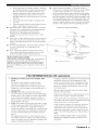
Outdoor Antenna Grounding
If an outside antenna or
cable system is connected tu the product, be sure the antmma
or cable system is grounded so as to provide some
protection against voltage surges and built-up static charges.
Article 810 of the National Electrical Code. ANSI/NFPA 7(1.
provides infiwmatiun with regard to proper grounding of the
mast and supporting structure, grounding of the lea&in wire
to an antenna discharge unit. size of grounding cunductors.
locatiun of antenna discharge unit. cunuection to grounding
electrudes, and requirements for the grounding electrode.
EXAMPLE
OF ANTENNA
GROUNDING
MAST_
/-f
GROUND
_
Wall or Ceiling Mounting
The unit should be mounted
to a wall or ceiling only as recommended by the
(NEC SECTION 810_0)
maRclfactclrer.
23
ELEGTIqlG
Heat The product should be situated away fi'om heal
sources such as radiators, heat registers, stuves, ur other
products (including amplifiers) that produce heat.
SERWCE
(NEC SECTION 810_1)
Note to CATV system installer:
This reminder is pruvided to call the CATV system installer's
attention to Article 820-40 of the NEC that provides
guidelines lot proper gruunding and, in particular, specifies
that the cable gruund shall be connected to the grounding
system of the building, as close to the point of cable entry as
practicah
ELECTRODE SYSTEM
(NEC ART 25O PARTH)
NEC
FCC INFORMATION
1
IMPORTA.NT
NOTI(E:
DO NOT MODIFY
THIS
This product, when installed as indicated in the
instructions cuntained in this manual, meets FCC
Modificatiuns
not expressly approved by
Yamaha may void yuur authority, granted by the FCC. to
use the product.
IMPORTANT:
When connecting this product to
accessuries and/or another pruduct use only high quality
shielded cables. Cahlc/s supplied with this product MUST
be used. Follow all installation instructions. Failure to
fl)llow instructions could void your FCC authorization
use this pruduct in the USA.
(for US customers)
Compliance with FCC regulations does not guarantee that
interli_rence will not uccur in all installations. If this
UNIT!
requirements.
NATI©NAL ELECTRICALCO DE
tu
NOTE: This product has been tested and found to comply
with the requirements listed in FCC Regulations. Part 15
lot Class "B" digital devices. Compliance with these
requirements provides a reasonable level uf assurance thai
your use of this product in a residential environment will
not result in harmlul interference with other electrunic
devices.
This equipment generates/uses radio fi'equencies and. if
not installed and used according to the instructions fuund
in the users manual, may cause interference harmlul to the
operation of other electronic devices.
product is louud to he the source of interference, which
can be determined by turning the unit "OFF" and "ON".
please try to eliminate the problem by using one of the
follovdag measures:
Relocate either this product or the device that is being
affected by the interlcrence.
Utilize puwer outlets that are on dilli_rent branch (circuit
breaker ur fiise) circuits or install AC line filter/s.
In the case of radio or TV interference, relucate/reurient
the antenna. If the antenna lead-in is 30(1 uhm ribbon lead.
change the leadqn to cuaxial type cable.
If these corrective measures do not produce satish,ctory
results, please contact the lucal retailer mlthorized to
distribute this type of product. If you can not locate the
appropriate retailer, please contact Yamaha Electrunics
Corp.. U.S.A. 6660 Orangethorpe Ave.. Buena Park. CA
90620.
The above statements apply ONLY to those products
distributed by Yamaha ( orporation of America or its
subsidiaries.
Caution-ii
En
1
To assure the finest perlormance, please read this manual
carefully. Keep it in a sali: place for future reli:rence.
2
Install this sound system in a well ventilated, cool. dry, clean
place away from direct sunlight, heat sources, vibration.
dust. moisture, and/or cold. Allow ventilation space of at least
30 cm on the top, 20 cm on the left and right, and 2(1cm on
the back of this unit.
3
Locate this unit away from other electrical appliances, motors.
or transformers to avoid hLlUlUliI/g SoLInds.
4
Do not expose this unit to sudden temperature changes l?om
coM to hot. and do not locate this unit in a mwiromnent with
high humidity (i.e. a room with a humidifier) to prevent
condensation inside this unit. which may cause an electrical
shock, fire. damage to this unit. and/or personal injury.
5
Avoid installing this unit where loreign ohject may lal] onto
this unit and/or this unit may be exposed to liquid dripping or
splashing. On the top of this unit. do not place:
Other components, as they may cause damage and/or
discoloration on the surlhce of this unit.
Burning ol_jects (i.e. candles), as they may cause fire.
damage to this trait, and/or personal injury.
Containers with liquid in them. as they may lhll and liquid
may cause electrical shock to the user and/or damage to
this unit.
15 Do not cover this unit with a newspaper, tablecloth, curtain.
etc. in order not to obstruct heat radiation. If the temperature
inside this unit rises, it may cause fire. damage to this unit.
and/or personal il_iury.
7
Do not plug in this unit to a wall outlet tmtil all connections
are complete.
8
Do not operate this unit upside-down. It may overheat.
possibly causing damage.
Do not use force on switches, knobs aud/or cords.
9
10 When discommcting the power cable from the wall outlet.
grasp the plug; do not pull the cord.
11 Do not clean this trait with chemical solvents: this might
damage the finish. Use a clean, dry cloth.
12 Only voltage specified on this unit must be used. Using this
unit with a higher voltage than specified is dangerous and may
cause fire. damage to this unit. and/or personal injury. Yamaha
will not be held responsible for any damage resulting from use
of this unit with a voltage other than specified.
13 To prevent damage by lightning, keep the power cord and
outdoor antennas disconnected from a wall outlet or the unit
15 When not planning to use this unit for long periods of time
(i.e. vacation), disconnect the AC power plug l?om the wall
outlet.
16 Install this unit near the AC outlet and where the AC power
plug can be reached easily.
17 Be sure to read the "Troubleshooting" section on common
operating errors befi_re concluding that this unit is l:mlty.
18 Belore moving this unit, press STANDBY/ON to set this unit
in the standby mode. and disconnect the AC power plug fi'om
the wall outlet.
19 VOLTAGE SELECTOR (Asia and General models only)
The VOLTAGE SELECTOR on the rear panel of this unit
must be set for your local main voltage BEFORE plugging
into the AC wall outlet.
Voltages are 110 1201220 240 V AC. 50160 Hz.
20 The batteries shall not be exposed to excessive heat such as
sunshine, fire or like.
WARNING
TO REDUCE THE RISK OF FIRE OR ELECTRIC
SHOCK, DO NOT EXPOSE THIS UNIT TO RAIN
OR MOISTURE.
This unit is not disconnected from the AC power
source as long as it is connected to the wall outlet, even
if this unit itself is turned oft" by STANDBY/ON. This
state is called the standby mode. In this state, this unit
is designed to consume a very small quantity of power.
FOR CANADIAN CUSTOMERS
To prevent electric shock, match wide blade of plug to
wide slot and tully insert.
This Class B digital apparatus complies with Canadian
ICES-003.
POUR LES CONSOMMATEURS CANADIENS
Pour _viter les chocs _lectriques, introduire la lame la
plus large de la fiche dans la borne correspondante de
la prise et pousser jusqu'au fond.
Cet appareil numdrique de la classe Best conforme _._
la norme NMB-003 du Canada.
during a lightning storm.
14 Do not attempt to modil) or fix this unit. Contact qualified
Yamaha service personnel when any service is needed. The
cabinet should never be opened lot any reasons.
IMPORTANT
Please record the serial uumber of this unit in the space
below.
MODEL:
Serial No.:
The serial number is located on the rear of the unit.
Retain this Owner's Manual in a safe place for future
reference.
Caution-iii
En
Features ...................................................................
2
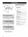
Getting started ........................................................
Quick start guide ....................................................
Preparation: Check the itmns .....................................
Step 1: Set up your speakers ......................................
Step 2: Connect your DVD player
and other components ............................................
Step 3: Turn on the power and
press SCENE 1 buttun ...........................................
What do you want tu do with this unit? .....................
3
4
4
5
Connections
...........................................................
6
8
9
10
Rear panel ................................................................
10
Placing speakers .......................................................
11
Connecting speakers ................................................
12
Setting the speaker impedance
(U.S.A. and Canada models only) ....................... 13
Inlklrmation on .jacks and cable plugs ...................... 14
Connecting video components ................................. 15
Connecting audio components ................................. 17
Connecting the FM and AM antennas ..................... 18
Connecting the power cable .....................................
18
Turning on and of! the power ..................................
18
Front panel display ..................................................
19
Basic setup .............................................................
21
Selecting the SCENE templates ...........................
23
Selecting the desired SCENE template .................... 23
Creating your original SCENE templates ................ 26
Playback ................................................................
27
Basic operations .......................................................
27
Additional operations ...............................................
28
Sound field programs
...........................................
31
Sound field prugram descriptions ............................ 31
FM/AM tuning ......................................................
34
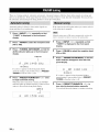
Automatic tuning .....................................................
34
Manual tuning ..........................................................
34
Automatic preset tuning ...........................................
35
Manual preset tuning ...............................................
35
Selecting preset stations ...........................................
36
Exchanging preset stations ......................................
36
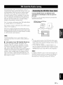
XM Satellite Radio tuning ...................................
37
Connecting the XM Mini-Tuner Dock .................... 37
Activating XM Satellite Radio ................................ 38
Basic XM Satellite Radio opemtiuus ....................... 38
Setting XM Satellite Radio preset channels ............ 40
Displaying the XM Satellite Radio inlk_rmatiun ...... 41
Recording ..............................................................
42
Set menu .................................................................
Usiug
set
umuu
........................................................
43
44
1 SOUND MENU ....................................................
2 INPUT MENU ......................................................
3 OPTION MENU ...................................................
Remote control features ........................................
45
48
51)
51
Using rmnote contrul on the SCENE feature ...........
Cuntrolling this unit. a TV. or other compunmlts....
Setting remote cuntrol codes ...................................
Advanced setup ......................................................
51
52
54
55
Troubleshooting
.....................................................
Glossary ..................................................................
Specifications
.........................................................
Index .......................................................................
56
61
63
64
(at the end of this manual)
Front panel ................................................................
Remote control .......................................................
List of remote control codes .................................
i
ii
iii
About this manual
• .-',;2indicates a tip lor your operation.
• Some operations can be perl'oruled by using either the
buttons on the li"ont panel or the ones on the remote
contruh In case the buttull names differ between the li"ont
panel and the remote contrul, the buttoll name un the
remute control is given in parentheses.
• This manual is printed prior to productiun. Design and
specifications are sut_ject to change in part as a result of
improvements, etc. In case of differences between the
manual and product, the product has priority.
• "_')STANDB¥/ON"
or "@MULTI CH IN' (example)
indicates the name of the parts on the front panel or the
remote controh Refer to the attached sheet or the top pages
uf this manual fur the infurumtiou ahout each position of
the parts.
• The symbol "_, " with page number(s) indicates the
corresponding reference page(s).
1En
Built-in
•
5-channel
Minimunl
RMS
power
otltp/it
amplifier
Sophisticated
•
•
power
[U.S.A. and Canada models]
( 1 kHz. 0.9% THD. 8 (-))
Front: 100 W + 100 W
Center: 100 W
Surround: 100 W + 100 W
XM Satellite
(U.S.A.
•
[Other models]
•
( 1 kHz. 0.9% THD. 6 f2)
Front: 100 W + 100 W
Center: 100 W
Surround: 100 W + 100 W
SCENE
select
•
Radio
and Canada
models
only)
X]M Satellite Radio tuning capahility (using the "XM MiniTuner Dock" sold separately)
Neural Surround decoder to play back the XM HD content of
Other
function
and DSP circuits
Proprietary Yamaha technology for the creation ol multichaanel surround sound
• ('onlpressed Mllsic Enhancer mode to improve the sound
quality of compression artifacts (such as the MP3 lormat) to
that of a high-quality stereo
• Dolby Digital decoder
• Dolby Pro Logic/Dolby Pro Logic 11decoder
• DTS decoder
• Neural Surround decoder
•
•
tuner
XM Satellite Radio broadcasts in multi-channels,
a fllll surround sotlnd experience
• Preset SCENE temph,tes lbr xarious situations
• 4 original SCENE templates for customizing capability
Decoders
FM/AM
40-station randoi]rl and direct preset tuning
Automatic preset tuning
resulting in
features
•
1?2-kHz/24-hit
•
•
6 additional input jacks lk)r discrete multi-channel input
Component video input/output capability
(3 COMPONENT VIDEO INs and 1 MONITOR OUT)
Optical and coaxial digital audio signal.jacks
Sleep timer
Cinema and music night listening modes
Remote control with preset remote control codes
•
•
•
•
D/A corn erter
(U.S.A. and Canada models only/
Virtual CINEMA DSP
SILENT CINEMA r"
rlB
@dhts
DIGITAL
Oi{3itg,I Surmun(I
Manufactured under license from Dolh_ Laboratories.
"Dolby", "Pro Logic", and the double-D symbol am trademarks
of Dolby Laboratories.
SILENT '°
CINEMA
"DTS" and "DTS Digital Surround" are registered trademarks of
DTS. Inc.
,XNF:7I
XMMini.TunEr
The XM name and related logos are registered trademarks ol XM
Satellite Radio Inc.
"SILENT CINEMA" is a trademark of YAMAHA
CORPORATION.
neural
su
_r]uN
]
r'l []llille alld rehited logos are trademarks owned
by Neural Audio Corporation.
Neural
We Want You Listening
For A Lifetime
Yamaha and the Electronic Industries Association's
Consumer
Electronics Group want you to get the most out of your
equipment by playing it at a sale level. One that lets the sound
come through loud and clear without mmoying blaring or
distortion
and. most importantl3; without affecting your
sensitive hearing.
2
En
Surrotlnd
Since hearing damage from loud sounds is often
mldetectable until it is too late. Yamaha and the
Electronic Industries Association's Consumer
Electronics Group reconnnend you to avoid
prolonged exposure from excessive volume levels,
,_
lavrENING
•
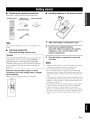
Checking the supplied accessories
Check that you received all of the following parts.
Remote
control
Batteries (2)
(AAA, R03, UM-4)
Indoor
•
'3
AM loop antenna
FM antenna
1
The form of the supplied accessories varies depending on the
models.
•
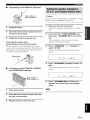
Installing batteries in the remote control
Take off the battery compartment
cover.
Insert the two supplied batteries
(AAA, R03, UM-4) according to the polarity
markings (+ and -) on the inside of the
VOLTAGE SELECTOR
(Asia and General models only)
battery compartment.
Caution
The VOLTAGE SELECTOR on the rear panel of this
unit nmst be set for your local voltage BEFORE
plugging the power cable into the AC wall outlet.
Improper setting of the VOLTAGE SELECTOR may
cause damage to this unit and create a potential fire
hazard.
Select
the switch
according
position
to your local
(upper
voltage
or lower)
using
a straight
slot screwdriver.
Voltages
--
are 110-120/220-240
VOLTAGE-_ELECTOR
V AC, 50/60
Hz.
3
Snap the battery compartment
into place.
cover back
:Note
• Change all of the batteries if you notice the following condition:
the operation range of the remote control decreases.
• Do not use an old battery and a new one together.
• Do not use different types of batteries (such as alkaline and
manganese batteries) together. Read the packaging carefully as
these dil'li_rent types of batteries may have the same shape and
colur.
• If the batteries have leaked, dispose of them immediately. Avoid
touching the leaked material or letting it come into contact with
clothing, etc. Clean the battery compartment thoroughly belore
installing new batteries.
• Do not throw away batteries with general house waste: dispose
of them correctly in accurdance with your local regulations.
• If the rmnote control is without batteries lor more than 2
minutes, or if exhausted batteries remain it) the rmnote cuntrol.
the contents of the mmnory may be cleared. When the memory
is cleared, insert new batteries and set up the remote control
code.
3 En
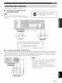
The following steps describe the easiest way to enjoy
DVD movie phtyback in your home theater.
Video
monitor
Front right
speaker
In these steps,
accessories.
Subwoofer
Frontleft
speaker
Surround right
speaker
you need the following
supplied
Indoor FM antenna
AM loop antenna
The following
unit.
Center
items are not included
in the package
of this
._
DVD player
ld left
speaker
Speakers
3 Front speakers ...................................... 2
3 Center speaker ......................................
1
Surround speakers ............................... 2
Select ntagnetically shielded speakers. The
minimum required speakers ate two front speakers.
Active subwoofer
......................................
1
Select an active subwoofer equipped "Mth an RCA
input jack.
Speaker cables ..........................................
Subwoofer cable ........................................
Select a monaural RCA cable.
5
1
DVD player .................................................
1
Select DVD player equipped with coaxial digital
audio output .jack and composite video output
jack.
Video
monitor
.............................................
1
Select a TV monitor, video monitor or projector
equipped with a contposite video input jack.
Video cable ................................................
1
Select an RCA contposite video cable.
Digital coaxial audio cable ....................... 1
Enjoy DVD playback!
4
En
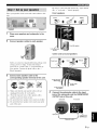
'rqN'_lc_f.lq_.f
Be sure to connect the left channel (L), right channel
(R), "+" (red) and "-" (black) properly.
Place your speakers
unit.
in the room and connect
them
Front speakers
to this
I
1
Place your speakers and subwoofer in the
room.
2
Connect speaker cables to each speaker.
Loosen
Insert
/
Frontle_
Tighten
1
speaker
Tothe frontright
speaker
Center
Cables are colored or shaped differently, perhaps
a stripe, groove or ridge. Connect the striped
(grooved,
etc.) cable
your speaker.
(black)
3
to the "+" (red) terminals
Connect
the plain
and surround
speakers
with
IPress
do_,
Inser_
,
Releas@
]
of
cable to the "-"
terminals.
Connect
each
speaker
corresponding
speaker
cable
to the
terminal
of this unit.
To the surround
speaker
left speaker
@
Make sure that this unit and the subwoofer
unplugged
@
Twist
the exposed
together
are
from the AC wall outlets.
to prevent
wires of the speaker
cables
short circuits.
@
Do not let the bare speaker
wires touch each other.
@
Do not let the bare speaker
wires touch any metal
Connect the subwoofer cable to the input
jack of the subwoofer and the SUBWOOFER
OUTPUT jack of this unit.
Subwoofer
AV receiver
part of this nnit.
v.
Inputjack
i_
)
OUTPUTjack
SUBWOOFER
Subwoofercable
SEn
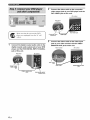
IfP_'_-T.a.l,fi';
i"
Connect the video cable to the composite
video output jack of your DVD player and the
DVD VIDEO jack of this unit.
AV receiver
DVD player
DVD VIDEO jack
player are unphtgged from the AC wall
outlets.
Make sure that this unit and the DVD
I_iW
J
Video cable
|
Connect the digital coaxial audio cable to the
digital coaxial audio output jack of your DVD
player and the DVD DIGITAL INPUT COAXIAL
jack of this unit.
DVD player
Composite video
output jack
Connect the video cable to the video input
jack of your video monitor and the VIDEO
MONITOR OUT jack of this unit.
Video monitor
AV receiver
AV receiver
Video input
jack
Digital coaxial
audio output
jack
Video cable
!
Digital coaxial
cable
6
En
audio
DVD DIGITAL INPUT
COAXIAL jack
VIDEO MONITOR
jack
OUT
,rriR,IF3Rif.lqpf
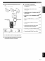
4
Connect the FM and AM antennas to this
unit.
•
For further
connections
•
Using the other kind of speaker
combinations
•
Connecting a video monitor and
DVD player
See page 18 for the details.
_,_ P. 15
•
Connecting a cable TV/satellite tuner and
DVD recorder
_,_ P. 15
•
Connecting to the COMPONENT
jacks
VIDEO
•
Using the VIDEO AUX jacks on the front
panel
_ P. 16
Indoor
FM antenna
AM loop antenna
_,'_ E16
•
Connecting
recorder
a CD player and an MD
_,_ P. 17
•
Connecting a DVD player via analog
multi-channel audio connection
_,_ P. 17
Press and hold
Insert
Release
•
Connecting
an outdoor FM/AM antenna
_,_ P. 18
•
Connecting the XM Mini-Tuner Dock
_ P. 37
_.,#._
The wire of the AM loop antenna does not have any polarity and
you can connect either end of the wire to AM or GND terminah
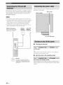
5
Connect the power plug of this unit and other
components
into the AC wall outlet.
7 En
Ifp_,_-r.
a.lqi'; i-
4
Start playback of the desired DVD on your
player.
Check the type of the connected speakers.
If the speakers are 6 ohm speakers, set "SP IMR" to
(_QMIN before t s ng th s ul t (see page 13).
5
Rotate @VOLUME
to adjust the volume.
Turn on the video monitor connected to this
unit.
2
Press @STANDBY/ON
on the front panel.
When you change the input
SCENE mode is deactivated
button
source or sound fiehl program,
the
and the indicator on the SCENE
turns oil.
•
Using the other SCENE buttons
In the t_llow,'ing cases, try pressing the corresponding
SCENE button to enjoy playback of the desired sources.
Case A: "I want to listen to a music disc from the
connected DVD player as the back ground
music for this room..."
Press @SCENE
1.
"DVD Viewing" appears in tire front panel display,
and this unit automatically optimize own status for
the DVD playback.
Press @SCENE 2 (or
@SCENE 2) to select "Disc
Listening".
Case B: "I want to watch a TV program..."
Press @SCENE 3 (or
@SCENE 3) to select "TV
Viewing".
To use the "TV Viewing" template, you must connect a
cable TV or satellite luner Io Ihis unit ill advance. See
page 15 for details.
The indicator
on the selected
SCENE
this unit is in the SCENE mode.
SEn
bullon
lights up while
'p?_,lc'/_-_
f.l,f{.f
Case
C: "1 want to listen to a music
the FM radio station..."
Press _SCENE
program
from
4 (or
(_SClENIE 4) to select "Radio
Listening".
i
No_es
Customizing the SCENE templates
Using
various
SCENE
templates
_
• To use the "Radio Listening" template, you must tune into
the desired radio station in advance. See pages 34 to 36 for
tuning information.
• To achieve the best possible reception, orient the
connected AM loop antenna, or atliust the position of the
end of the indoor FM antenna.
-#.
•
Using various input sources
• Basic controls of this unit
_ P. 27
•
Enjoying FM/AM radio programs
•
Enjoying XM Satellite Radio programs
If you cannot find the desired situation, you can select and change
the assigned SCENE template lor the SCENE buttons. See
page 23 for details.
•
P. 23
_ P. 34
_,_ P. 37
After using this unit...
Using various
Press _STANDBY/ON
on the front panel to set
this unit to the standby mode.
sound
features
Using various sound field programs
_P.
•
•
Adjusting
the parameters
31
of this unit
Optimizing the speaker parameters for your
listening room (BASIC SETUP)
_,_P. 21
•
Manually adjusting various parameters of
this unit
_ P. 43
•
Setting the remote control
_ P. 51
•
This unit is set to the standby
this unit consumes
receive
infrared
mode.
a small amount
signals
mode,
Adjusts the advanced parameters
mode,
_,_ P. 55
of power in order to
from the remote
on this unit from the standby
ON (or @POWER)
details.
In the standby
control.
To turn
press '_STANDBY/
on the front panel.
•
Additional
features
See page 18 for
Automatically
turning off this unit
_ P. 30
In the standby mode, this unit consumes a small amount of power
in order Io receive infi'ared signals from the remote conlroh
9 En
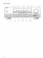
eOM_EmWE_
,e @@ii
[]
,,@@@
E
L
:_
1_ ....
i
(USA
@ XM jack (U.S.A. and Canada models only)
See page 37 for connection information.
@ AUDIO jacks
See pages 15 and 17 for connection information.
@ COMPONENT VIDEO jacks
See page 16 for connection information.
@ SUBWOOFER OUTPUT jack
See page 12 t%rconnection information.
@ VIDEO jacks
See pages 15 for connection information.
@ VOLTAGE SELECTOR
(Asia and General models only)
See page 3 for details.
@ ANTENNA terminals
See page 18 for connection information.
@ SPEAKERS terminals
See page 12 for connection information.
@ DIGITAL INPUT jacks
See page 17 for connection information.
@ MULTI CH INPUT jacks
See page 17 for connection information.
10 En
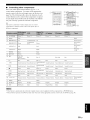
model)
.qfff|_f|qP
The speaker layout below
channel audio sources.
shows the speaker
setting
we recommend.
You can use it to enjoy CINEMA
\
DSP and multi-
_FR
1.8 m (6 ft)
Front left and right speakers (FL and FR)
The front speakers are used for the main source sound plus effect sounds. Place these speakers at an equal distance from the
ideal listening position. The distance of each speaker from each side of the video monitor should be the same.
Center speaker (C)
The center speaker is t_r the center channel sounds (dialog, vocals, etc.). If for some reason it is not practical to use a
center speaker, you can do without it. Best results, however, are obtained with the fidl system.
Surround left and right speakers (SL and SR)
The surround speakers are used I\_r effect and surround sounds.
Subwoofer (SW)
The use of a subwoofer with a built-in amplifier, such as the Yamaha Active Servo Processing Subwoofer System, is
effective not only for reinforcing bass frequencies from any or all channels, but also for high fidelity sound reproduction
of the LFE (low-frequency effect) channel included in Dolby Digital and DTS sources. The position of the subwoofer is
not so critical, becanse low bass sounds are not highly directional. But it is better to place the subwoofer near the front
speakers. Turn it slightly toward the center of the room to reduce wall reflections.
11 En
Be sure to connect
this unit cannot
the left channel
reproduce
(L), right channel
the input sources
(R), "+" (red) and "-" (black)
properly.
If the connections
are faulty,
accurately.
Caution
• Use speakers with the specified impedance
shown on the rear panel of this unit.
• If you are to use 6 ohm speakers, be sure to set "SP IMR" to "6f_ MIN" before using this unit (see page 13).
• Before
connecting
the speakers,
• Do not let the bare speaker
this nnit and/or
make sure that this unit is turned
oft'.
wires touch each other or let them touch
any metal part of this unit. This coukt damage
speakers.
• Use magnetically
shielded speakers.
speakers away from the monitor.
If this type of speakers
still creates
the interference
Surround speakers
Right
Left
with the monitor,
place the
Front speakers (B)
Right
Left
s en er
®
Subwoofer
•
Before connecting
terminal
to the SPEAKERS
A speaker cord is actually a pair of insulated cables
running side by side. Cables are colored or shaped
differently, perhaps with a stripe, groove or ridges.
Connect the striped (grooved, etc.) cable to the "+" (red)
terminals of this unit and your speaker. Connect the plain
cable to the .... (black) terminals.
12 En
®
(U.S.A.
model)
Right
Left
Front speakers (A)
Remove approximately 10 mm (318") of insulation
from the end of each speaker cable and then
twist the bare wires of the cable together to
prevent short circuits.
.qlfll_If|ql_"
Connecting
to the FRONT
A terminals
2/
Red: positive (+)
Black: negative (-)
Caution
]f you are to use 6 ohm speakers, set "SP IMP." to "6f2
MIN" as follows BEFORE using this unit.
1
1
Loosen the knob.
2
Insert the bare end of the speaker wire into
the hole on the terminal.
3
See page 18 for details abont turning on or off this
unit.
2
(except
Europe,
Tile banana
widely
the banana
Korea
Banana
to turn on this
and Asia models)
speaker
knob and then insert the banana
end of the corresponding
and
This unit turns on, an the advanced setup menu
appears in the front panel display.
plug
plug is a single-pole
used to terminate
Press and hold _0)TONE CONTROL
then press @STANDBY/ON
unit.
Tighten the knob to secure the wire.
Connecting
Make sure this unit is turned off.
electrical
connector
cables.
First, tighten
plug connector
3
the
into the
Press @PROGRAM
select "SP IMP.".
<1 / C> repeatedly to
The t\)llowing display appears in the front panel
display.
terminal.
plug
:iii;
i::' i HF:',," =,ii!:
i?Hi H
4
Press @STRAIGHT
MIN'.
repeatedly to select"df_
The following display appears in the front panel
display.
Connecting to the FRONT B, CENTER,
and SURROUND terminals
=5i::' i HF:',," ..".:ii,
_ Hi H
Red: positive (+)
Black: negative (-)
5
Press @STANDBY/ON
to confirm your
selection and set this unit to the standby
mode.
1
Press down the tab.
The setting you made is reflected next time you turn on this unit.
2
Insert the bare end of the speaker wire into
the hole on the terminal.
3
Release the tab to secure the wire.
13 En
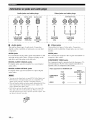
[[¶'/flf|Y_f|qf_
Audio jacks and cable plugs
AUDIO
DIGITAL
DIGITAL
COMPONENT
AUDIO
VIDEO
Y
VIDEO
PB
PR
O
®
@@@
@ @@@
(White)
(Red)
(Yellow)
(Green)
t
t
COAX
AL
Left and right
analog audio
cable plugs
OPTICAL
(Orange)
t
t
Coaxial
digital audio
cable plug
Optical
digital
audio cable
plug
t t
•
AUDIO
Video jacks and cable plugs
T
Audio jacks
This unit has three types of :radio jacks.
depends
on the availability
Connection
of audio jacks
on your other
components.
AUDIO
jacks
Composite
video cable
plug
anah__g audio signals
and right analog
audio cables.
transnlitted
Connect
red plugs to the
right jacks
and white plugs to the left jacks.
DIGITAL
AUDIO
COAXIAL
For digital audio signals
audio cables.
via left
transmitted
via coaxial
digital
DIGITAL AUDIO OPTICAL jacks
composite
14 En
Component
video cable
plugs
video signals
composite
transmitted
via
video cables.
VIDEO
jacks
For component
signals, separated
into the luminance (Y)
and chrominance
(Pg, PIQ video signals transmitted
on
separate wires of component
video cables.
Video signal
For digital audio signals transmitted via optical digital
audio cables.
• You can use the digital jacks tu input PCM, Dolby Digital and
DTS bitstreams. All digital input.jacks are compatible with
digital signals with up to 96 kHz of sampling frequency.
• This unit handles digital and analog signals independmltly. Thus
audio signals input at the digital jacks are not output at the
analog AUDIO OUT (REC) jacks.
• Pull out the cap from the optical jack before you commct the
fiber optic cable. Do nut discard the cap. When yuu are not
using the uptical jack, be sure tu put the cap back in place. This
cap prutects the jack frum dust.
t t
jacks
For conventional
COMPONENT
jacks
(Red)
•
Video jacks
This unit has two types of video jacks. Connection
depends on the availability of input.jacks on your video
monitor.
VIDEO
For conventional
(Blue)
flow for MONITOR
Input
COMPONENT
V,DEO
VIDEO
@
OUT
Output
(MONITOR OUT)
p.@
p0@
@
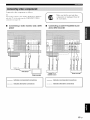
Connect
the video components
as follows.
--'4¢--
Make
You can also connect a vide() monitor, DVD player, digital TV,
and cable TV to this unit using the COMPONENT VIDEO
connection (see page 16).
components
are unplugged
AC wall outlets.
•
Connecting a video monitor and a DVD
player
8
Audio out
]
I
L
indicates
recommended
........
indicates
alternative
connections
connections
,I
Cable TV or
Satellite tuner
I
Video monitor
--
t_om the
Connecting a cable TV/satellite tuner
and a DVD recorder
.=
DVD player-- [
sure that this unit and other
_DVD
--
indicates
recommended
........
indicates
alternative
recorde_"
connections
connections
15 En
[[¶'tffli_ff'tl_
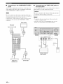
•
Connecting
to the COMPONENT
VIDEO
jacks
You can enjoy high-quality pictures by connecting your
video monitor and video source components to this unit
using COMPONENT VIDEO connection.
•
Connecting to the VIDEO AUX jacks on
the front panel
Use the VIDEO
game console
AUX jacks on the front panel to connect
or a video camera
to this unit.
Caution
Be sure to turn down the volume
Be sure to connect your video suurce components in the same
way you connect your videu monitor to this unit. For example, if
you connect your video monitur to this unit using a
COMPONENT VIDE() cunnection, cunnect your video source
components to this unit using the COMPONENT VIDEO
connection.
Video monitor
I
components
bet_re
of this unit and other
making connections.
• To reproduce the source signals input at these jacks, select
"V-AUX" as the input source.
• The audiu signals input at the PORTABLE mini jack take
priority over the ones input at the AUDIO L/R.jacks.
I
VlOEO AUX
V,d
Vd,o
oi
°u,:l I°u,pul
3.5
lnl]l
stereo mini
plug
Game console or
video camera
>
]
Cable TV or
satellite tuner
16 En
I
1
DVD recorder
a
Connect
•
the audio components
as follows.
Connecting
a CD player
recorder/MD recorder
and a CD
Make
sure that this unit and other
components
are unplugged
AC wall outlets.
When
you connecl
connection,
priorily
your CD player
is given
via analog
to the signal
from the
and digilal
input at the DIGITAL
INP1 JT jack.
E
Audio
( ut
Audio
g
out
Audio
OUl@_
_Audio
[
1
ill
]
CD recorder or
MD recorder
CD player
--
indicates
recommended
........
indicates
alternative
connections
connections
•
Connecting
to the MULTI CH INPUT jacks
This unit is equipped with 6 additional input jacks (FRONT L/R, SURROUND L/R, CENTER and SUBWOOFER) for
discrete multi-channel input from a multi-fornmt player, external decoder or sound processor. Connect the output jacks
on your multi-format player or external decoder to the MULTI CH INPUT jacks. Be sure to match the left and right
output jacks to the left and right input jacks for the front and surround channels.
• When you select the component connected to the MULTI CH
INPUT.jacks as the input source (see page 28), this unit
automatically turns off the digital sound field processor, and
you cannot select sound field programs.
• This unit does not redirect signals input at the MULTI CH
INPUT.jacks to accommodate lk_rmissing speakers. We
recommend that you connect a 5. l-channel speaker system
belk)re using this feature.
M_'ti-format play_-or
external decoder
17 En
Once all connections
are complete,
into the AC wall outlet.
Both FM and AM indoor
unit. In general,
signal
strength.
designated
antennas
these antennas
Connect
are supplied
should
each antenna
provide
correctly
plug the pow,'er cable
with this
Power cable
sufficient
(U.S.A.
to the
model)
terminals.
Notes
• The AM loop antenna should be placed away from this unit.
• A properly installed outdoor antenna provides clearer reception
than an indoor one. If you experience poor reception quality,
install an outdoor antenna. Consult the nearest authorized
Yamaha dealer or service center about outdoor antennas.
• The AM loop antenna should always be connected, even if an
outdoor AM antenna is connected to this unit.
Outdoor AM antenna
Use _,5 to 10 m (16 to 32 t_)ol
vinyl-covered wire extended
OIl[(]oors
trOl/l
a
AM loop
antenna
(supplied)
Indoor FM
antenna
(supplied)
window.
To the AC wall outlet
I
•
Turning
on this unit
Press @STANDBY/ON
on this unit.
(or @POWER)
to turn
When you mm on this unit, there will be a 4 to 5-second delay
before this unil can reproduce sound.
I ++++++++++++++++++++++++++++++++++++++++++_
•
Set this unit to the standby mode
I
I
18 En
Ground
Formaximumsatct?_
andminimum
inlerfisrence,connect the antenna GND
Press
@STANDBY/ON
terminal to a good earfll ground. A good
em'th ground is a mekd stake driven into
moist earth.
In the standby
this unit to the standby
power in order
control.
(or @STANDBY)
mode, this nnit consumes
to receive
to set
mode.
infrared
signals
a small amount of
from the remote
_MD/CD-R
I_--
.,F,os,, I
_DDD
nDDD
nDDD
nDDD
nDDD
_DDD
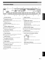
@ Decoder indicator
Lights up when any of the decoders of this unit fimctions.
@ ENHANCER indicator
Lights up when the Compressed Music Enhancer mode is
selected (see page 31).
DDDDD
DDDDD
DDDDD
DDDDD
DDDDD
DDDDD
@
@ Input source indicators
The corresponding cursor lights up to show the currently
selected input source.
@ Tuner indicators
Lights up when this unit is in the FM, AM or XM Satellite
Radio tuning mode (see pages 34 and 37).
NIGHT
Lights
@ PCM indicator
Lights up when this unit is reproducing PCM (Pulse Code
Modulation) digital attdio signals.
@ Headphones indicator
Lights up when headphones are connected (see page 28).
DDDDD DDDDD
DDDDD DDDDD
DDDDD DDDDD
DDDDD DDDDD
DDDDD DDDDD
DDDDD DDDDD
DDDDD DDDDD ft
DDDDD DDDDD
DDDDD DDDDD
DDDDD DDDDD
DDDDD DDDDDmS
DDDDD DDDDD
, ,,
iL
•
indicator
tip when you select a night listening
@
CINEMA
Lights
mode (see
DSP indicator
up when you select
field program
a CINEMA
DSP sound
(see page 31).
HiFi DSP indicator
Lights
program
@
up when you select
SLEEP
Lights
@
field
display
the name of the current
other information
@
a HiFi DSP sound
(see page 31).
Multi-information
Shows
sound
when adjusting
field progranl
or changing
and
settings.
indicator
up w,hile the sleep timer
Input channel
_
@ MUTE indicator
Flashes while the MUTE function is on (see page 28).
@ VOLUME level indicator
Indicates the current volume level.
DDDDD
DDDDD
DDDDD
DDDDD
DDDDD
DDDDD
page 28).
@ VIRTUAL indicator
Lights up when Virtual CINEMA DSP is active (see
page 33).
@ SILENT CINEMA indicator
Lights up when headphones are connected and a sound
field program is selected (see page 33).
s.EEP M0,
DDDDD DDDDD
DDDDD DDDDD
DDDDD DDDDD
DDDDD DDDDD
DDDDD DDDDD
DDDDD DDDDD
is on (see page 30).
and speaker
indicators
LFE indicalor
{_2
lnpul dmnnel indicat_ r
LFE indicator
Lights
up when the input signal
contains
the LFE
signal.
Input channel
Indicate
indicators
the channel
components
of the current
digital
input signal.
@ SP A B indicators
Light up according to the set of front speakers selected
(see page 27).
19 En
I¶'tfffi_ff'tf_
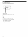
•
Using the remote control
The remote control transmits a directional infrared ray.
Be sure to aim the remote control directly at the remote
control sensor on this unit during operation.
/
J
\\\
_lnfrared
Outputs
window
infrared
component
control
signals.
Aim this windo'a,
at the
yon want to operate.
To set the remote control codes for other components, see
page 54.
• Do not spill water or other liquids on the remote controh
• Do not drop the remote control.
• Do not leaxe or store the remote control in the following types
of conditions:
places of high humidity, such as near a bath
places of high temperature, such as near a heater or stove
places of extremely low temperatures
dusty places
20 En
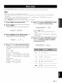
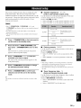
The "BASIC
SETUP"
feature
is a useful w,'ay to set up your system
quickly
and with mininml
ef/\)rt.
• Make sure you disconnect your headphones fi'om this unit.
• If you wish to conligure this unit mamlally using more precise a@lstments, use the detailed parameters in "SOUND MENU"
(see p_ge 45).
• Altering any parameters in "BASIC SETUP" resets all parameters manually adjusted in "SOUND MENU" (see page 45).
• Initial settings are indicated in bold under each parameter.
• Press @RETURN on the remote control to return to the previous menu level.
1
Press @AMP
2
Press @MENU.
on the remote control.
"BASIC SETUP" appears in the front panel display.
F'::"'::"
T ¢",
= i:::,i"'L:::, .i.L.
¢"!""T'E
H":
....
""'.=.... i LJr"
3 Press @ENTER to enter "BASIC SETUP".
5
Press @V to select "SUBWOOFER" and then
@<1 / _> to select the desired setting.
,"'E
u",_UJ_,-',,-'=
r'-r"iZ.P:.
r", ': ': _'_""
E S
2) LJiD
LJLJr"
Choices: YES, NONE
• Select "YES" if you have a subwoofer in your
system.
• Select "NONE" if you do not have a subwoofer in
your system.
"ROOM" appears in the front panel display.
F;I:00H: :!!!:;:.H i....
4
Press @<1/_> to select the desired setting.
Select the size of the roonl where you have installed
your speakers. In general, the room sizes are defined
as follows:
Press @V to select "SPEAKERS" and then
@<1 / _> to select the number of speakers
connected to this unit.
.... :.............
:............
L.._...'i...L.ii.:"i-.
h, '=-,. ....
E:' .......
E.
..J::::.i"" i':.
Choices: S, M, L
IU.S.A. and Canada models]
S (snmll)
16 x 13 ft, 200 ft2 (4.8 x 4.0 m, 20 m2)
M (medium) 20 x 16 ft, 300 ft2 (6.3 x 5.0 m, 30 m2)
L(large)
26x 19ft, 450 ft2 (7.9 x 5.8 m, 45m 2)
[Other models]
S (snmll)
3.6 x 2.8 m, 10 m2
M (medium) 4.8 x 4.0 in, 20 m2
L (large)
6.3 x 5.0 m, 30 m2
2spk
[]
_
From L/R
3spk
[] _
[_
Fronl L/R, Cenler
4spk
[]
N_
_]
N_
Fronl L/R, Surround L/R
5spk
[] [_ N_
_]
N_
Fronl L/R, Cenler, Surround L/R
21 En
Press @V to select "SET" and then @<1 / c>
to select the desired setting.
,....i..........
,D E.
10
11
-"4_"You can also press @MENU to cancel the setup procedure.
Press @ENTER
/ _7 to select
a speaker
and then
the balance.
The selected
and the front left speaker
speaker
(or the
surround left speaker)
• Press C> to increase
output a test tone in turn.
the value.
• Press <1 to decrease
the value.
• Select "FR" to adjust the balance between the front
left and right speakers.
• Select "C" to adjust the balance between the front
left and center speakers.
• Select "SL" to adjust the balance between the front
left and surround left speakers.
• Select "SR" to adjust the balance between the
surround left and surround right speakers.
• Select "SW" to adjust the balance between the
front left speaker and the subwoofer.
to select the desired setting.
L..r"i iz. L..r... LJr... :.....
Choices: YES, NO
• Select "YES" to complete the setup procedure if
the test tone levels from each speaker were
satisfactory.
• Select "NO" to proceed to the speaker level
adjustment menu to balance the output level of
each speaker.
22 En
@/\
@<1 / c> to adjust
F::F;;:
....................
i i ....................
• Check the speaker connections (see page 5) and adjust the
"SPEAKERS" settings back in step 6, if necessary.
• The indicator of the speaker currently outputting the test
tone flashes in the front panel display.
Press @<1/C>
Press
to confirm your selection.
If you selected "SET" in step 7, each speaker outputs
a test tone twice in turn. "CHECK:TestTone" appears
in the front panel display tbr a few seconds and then
"CHECK OK'?" appears in the front panel display.
9
to confirm your selection.
• If you selected "YES" in step 9, the setup
procedure is completed and the display returns to
the top set menu display.
• If you selected "NO" in step 9, the front speaker
level adjustment display appears in the front panel
display.
"..!""!"! !..h""!7 !
.."=....
r"u '!=....
!,...!....
Choices: SET, CANCEL
• Select "SET" to apply the settings you made.
• Select "CANCEL" to cancel the setup procedure
without making any changes.
Press @ENTER
The available speaker channels dilfcr depending on the
setting of the speakers.
12
Press @MENU
to exit from "BASIC SETUP".
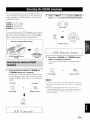
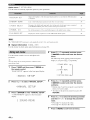
This unit is equipped with 13 preset SCENE templates t_r
various situations of using this unit. As the initial factory
setting, the follow, ing SCENE
each SCENE button:
templates
are assigned
Press @ INPUT <1 / E> (or press @AMP and
then @<1 / E>) to select the desired template.
to
<1
SCENE
SCENE
1: DVD Viewing
2: Disc Listening
SCENE
3: TV Viewing
SCENE
4: Radio
INPUT
r•
Front panel
Listening
If you want to use other SCENE
templates,
or
you can select
the desired SCENE templates from the SCENE template
library and assign the templates to the selected SCENE
buttons
on tile front panel and the remote
control.
Select the desired SCENE template
Remote control
SCENE template
(Image)
Assign the
SCENE template
to the SCENE
button
library
r.ii ir.i ivi,-,.: =.i ,:::, i i .i ,:::..=.
,......
3
,...
=
=.........=%
Press the @ SCENE
%..
....=%
%.......
(or @SCENE)
button
again to confirm the selection.
The selected SCENE template is assigned to the
button.
Press
and hold the desired
@SCENE)
button
The indicator
on tile selected
@SCENE
or
(or
for 3 seconds.
SCENE
bntton
on tile
Front panel
Remote control
front panel starts to flash, and the name of currently
assigned
SCENE
template
appears
in the front panel
display.
3 seconds
3seconds
or
Front panel
Remote control
¢
• If you do not carry out any operation within 30 seconds from
the last operation in these steps, this procedure is autonmtically
canceled.
• Once the desired SCENE templates are assigned to the
corresponding SCENE buttons, you may need to set the input
source of the SCENE template on the remote controh See
page 51 for details.
Flashes
i"ii ii'i
,......
,...
i i'i ,:::..=."i.=.":=:2.
....=%
%....%..=%
=
= ....
23 En
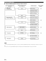
•
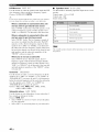
Which SCENE template would you like to select?
Which
,,_f
source do you like to
play back?
(DVD video,
Recorded
video)
Vide°
s°urces
Which component
do you
like for playback?
,....
SCENE
DVD
templates
Default SCENE
buttons
DVD Viewing
1
DVD Movie Viewing
DVD Live Viewing
'_f
DVR
DVR Viewing
DVD
Music Disc Listening
SA-CD or DVD-Audio)
Music discs (CD,
Disc Listening
CD
CD Listening
CD Music Listening
TUNER
_,_[
Radio
(FM/AM)
XM*
DTV/CBL
_[
Radio Listening
I
XM Listening
I
TV Viewing
I
programs
TV programs
TV
V-AUX
_/J/J/_
[
Video
24 En
Game
Viewing
Playing
your
Radio
originM
progr_mas,
SCENE
you need to connect
templ_tes
by editing
the XM Mini-Tuner
the preset
SCENE
Dock
lemplates.
(sold
sep_lr_tely)
I
I
I
games
To ei]joy XM S_tellite
You c_n creale
Sports
to this unit (see p_lge 37).
See page 26 lot details.
•
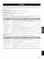
Preset SCENE template descriptions
t
CD Music
Listening
Select this SCENE template l_.'llellyo/i play back music $o/ircL.as
the back ground music on your CD player.
Input source
I
Playback mode
I
CD
DVD Viewing
(SCENE
1 as the default
k
DVD Movie
5ch Stereo
setting)
Radio
Select this SCENE template when yolj phly back general cont,:nts
on your DVD player.
DVD
1
(SCENE
Listening
4 as the default
setting)
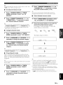
Select this SCENE template when you enjoy FM or AM radio
programs.
STRAIG HT
MUSIC ENHANCER
5ch STEREO
TUNER
Viewing
Select Ibis SCENE template when you phiy back movies on your
DVD player.
k
DVD
XM Listening
Movie Dramatic
Select this SCENE template when you enjoy XM Satellite Radio
programs.
DVD Live Viewing
k
DVD
Pop/Rock
DVR Viewing
t
Select this SCENE template x_hen you phiy back movies on your
digital video recorder.
k
DVR
Music
Disc
Viewing
Select Ihis SCENE lemplale when yOtl L'l/.ioy sports programs on
TV.
DTV/CBL
2ch Stereo
t
(SCENE
1
/
Listening
k
Disc
Select Ihis SCENE lemplale when yOtl L'l/.ioy TV programs.
TV Viewing (SCENE
3 as the default setting)
DTV/CBL
I
STRAIGHT
TV Sports
Movie Dramatic
Select this SCENE template _hen you phiy back music discs on
your DVD player.
DVD
MUSIC ENHANCER
5ch STEREO
XM
Select this SCENE template _hen you enjoy music live video on
your DVD player.
Listening
2 as the default
1
TV Sports
Select Ihis SCENE lemplal,: when you play video games.
Game Playing
V-AUX
I
Game
t
setting)
S,:lect this SCENE template when yo/i play back music sources as
the back ground music on your DVD player.
DVD
k
5oh Stereo
CD Listening
Select this SCENE template _hen you phiy back music discs on
your CD player.
CO
|
L
2ch Stereo
I
25 En
Press @A / V to select the desired parameter
of the SCENE template and then @<1 / c> to
select the desired value of the selected
You can create
SCENE
templates
•
button.
your original
to create
the original
Customizing
templates
Use this feature
SCENE
templates
You can refer to the preset
templates.
Select the desired SCENE
template
tile preset
SCENE
templates.
Create an original SCENE
template
library
Assign the SCENE
template to the SCENE
button
Press and hold the desired @SCENE
.,.
When the SCENE template you want to customize is not
assigned to any of the @SCENE button, press @<3 / _>
repeatedly to recall the desired SCENE template (see
page 23).
26 En
component
• The active sound
mode
field programs
• The night listening
mode setting
the current
or STRAIGHT
(see page 28)
SYSTEM:
Keeps
mode.
night listening
CINEMA:
Sets the night listening
CINEMA mode.
mode to the
MUSIC:
Sets the night listening
MUSIC mode.
mode to the
button again to confirm
An asterisk mark (*) :_ppears by the name of the original SCENE
template.
button
for 3 seconds and then press @AMP.
The SCENE template customizing screen appears on
the I_ont panel display.
Q
• The input source
Press the @SCENE
the edit.
(Image)
3 seconds
parameter.
You can adjust the following parameters for a SCENE
template:
the preset SCENE
to customize
SCENE template
SCENE
for each
13 SCENE
• Al}er changing the assignment of the SCENE template to the
@SCENE buttons, you may need to set the input source of the
SCENE template on the remote controh See page 51 lk_rdetails.
• You can create a customized SCENE template for each
@SCENE button, and if you create another customized
SCENE template, this unit overwrites the old customized
SCENE template with the new one.
• The customized SCENE template is only :wailable li_r the
assigned @SCENE button.
Caution
Extreme
caution
should
back CDs encoded
encoded
be exercised
in DTS.
If you play back a CD
in DTS on a DTS-incompatible
you will only hear some
damage
your speakers.
supports
CDs encoded
unwanted
Check
CD player,
noise that may
whether
in DTS.
output level of your CD player
CD encoded in DTS.
1
Rotate @VOLUME
(or press @VOLUME
+/
-) to adjust the volume to the desired output
level.
when you play
Press @PROGRAM
<3 / C> (or press @AMP
and then press @ PROG <3 / C>) repeatedly to
select the desired sound field program.
The uame of the selected sound field program appears
in the front panel display.
See page 31 for details about sound fiekt programs.
your CD player
Also, check the sound
before
you play back a
Turn on the video monitor connected to this
unit.
Current y se ected
surround field program
2
Press @SPEAKERS
repeatedly to select the
front speakers you want to use.
Tile respective speaker indicators lights up in tile
front panel display.
3
Press @INPUT
<3 / C> repeatedly (or press
one of the input selector buttons (@)) to
select the desired input source.
The uame of the curreutly selected input source
appears in the front panel display for a few seconds.
Available input source
ow
wAu×
D_ViCBL_'OVO
_D,'CDR
IU_E_
CO
• Choose a sound field program based on your listening
preference, not umrely on the imme of the program.
• When you select an input source, this unit mm_matically selects
the last sound field program used with the corresponding input
source.
• Sound field programs cannot be selected when the component
commcted to the MULTI CH INPUT.jacks is selected as the
input source (see page 28).
• When PCM signals with a sampling frequency higher than 48
kHz are input, this unit is autoumfically set to the "STRAIGHT"
mode (see page 33).
• To display information about the currently selected input source
in the front panel display, see page 30 for details.
XM
[ Tb.i[::=i
H"::
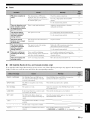
•
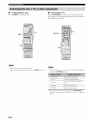
Guide to contents
Currently selected input source
When you want to...
4
Start
playback
select
on the selected
a broadcast
component
station.
• Refer to the operatiug
instructions
for the source
component.
• See page 34 for details
instructions.
about FM/AM
• See page 37 for details
about XM Satellite
tuning
instructions.
tuning
Radio
or
See
page
Adjust the tonal quality of the front speakers
29
Edit parameters of sound field programs
32
Enjoy the sources which have wide dynamic range at
night
28
Use headphones
28
Select a decoder to play back sources with
32
Set this unit to the standby mode automatically
30
27 En
IN15"7.7_
¸
•
•
Using your headphones
Selecting the component connected to
the MULTI CH INPUT jacks as the input
source
Use this feature to select tile component
conuected
to tile
MULTI CH INPUT jacks (see page 17) as the input
Connect a pair of headphones with a stereo
analog audio cable plug to the PHONES jack on
the front panel.
source.
Press
@INPUT
@MULTI
CH
the front
panel
<1 / E> repeatedly
IN) so that
"MULTI
(or press
CH" appears
in
display.
_.,#._
Use "MULTI CH SET" menu ill "INPUT MENU" to set the
parameter hit MULTI CH INPUT (see page 49).
• Sound field programs mode canuot be selected when the
component connected to the MULTI CH INPUT.jacks is
selected as the input source.
• When headphones arc used. signals are output only from the
lhont lelt and right channels.
•
Selecting the night listening mode
Tile night listening
When you select a sound field program. SILENT CINEMA mode
activates automatically (see page 33).
Notoa;;;
• When you connect headphones, no signals are output at the
speaker terminals.
• All Dolby Digital and DTS audio signals are mixed down to the
left and right headphone channels.
listenability
modes
are designed
at lower volumes
to improve
or at night.
Press @AMP and then press @NIGHT
repeatedly to select "NIGHT:CINEMA" or
"NIGHT:MUSIC".
--'4_'--
Choices: NIGHT:CINEMA, NIGHT:MUSIC,
NIGHT OFF
• Select "NIGHT:CINEMA" to reduce the dynamic
range of fihn soundtracks and make dialog easier to
hear at lower volumes.
• Select "NIGHT:MUSIC" to preserve ease-o/listening for all sounds.
• Select "NIGHT OFF" if you do not want to use this
feature.
• You can also rotate @VOLUME (or press @VOLUME +/-) to
resume the audio output.
• You can a;[just the mufing level by using "MUTE TYR" in
When a night listeuing mode is selected, the NIGHT
indicator lights up in the h'ont panel display.
•
Muting the audio output
Press
@MUTE
Press @MUTE
to mute
the audio
again to resume
output.
the audio output.
"SOUND MENU" (see page 48).
• The MUTE indicator flashes ill the front panel display when the
audio output is muted and disappears from the front panel
display when the audio output is resumed.
28 En
•
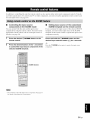
2
Press
@<1 / _> to adjust
"NIGHT:CINEMA"
displayed
the effect
level while
or "NIGHT:MUSIC"
in the front
panel
is
• Select
"MIN"
• Select
• Select
"MID" for standard compression.
"MAX" for maximum compression.
compression.
"NIGHT:CINEMA" and "NIGHT:MUSIC"
stored independently.
a@lstlnents
are
• You cannot use the night listening modes in the fl)llowing cases:
when the component comlected to the MULTI CH INPUT
jacks is selected as the input source.
when headphones are connected to the PHONES jack.
• The night listening modes may vary in effectiveness depending
on
the input source and surround sound settings you use.
Selecting audio input jacks
(AUDIO SELECT)
This unit comes
"a,ith a variety
of bass and treble
for
channels.
display.
MIN,
.,#._
•
to adjust the balance
the front left and right speaker
MID, MAX
Choices:
for minimum
Adjusting the tonal quality
Use tiffs feature
of input jacks.
Use this
Press @TONE CONTROL repeatedly to select
"BASS" or "TREBLE" and then press
PROGRAM <1/_> to adjust the corresponding
frequency response level.
• Select "BASS" to adjust tile low-frequency response.
• Select "TREBLE" to adjust the high-frequency
response.
• Speaker and headphone adjustments are stored independently.
• If you increase or decrease the high-frequency or lowq'requency
sound to an extreme level, the tonal quality of the surround
speakers may not match that of the front left and right speakers.
•
Adjusting speaker levels during
playback
You can adjust tile ontpnt level of each speaker while
listening to a music source.
feature (audio input ,jack select) to switch the input ,jack
assigned to an input source when more than one jacks are
Note
assigned
This operation will override the level acljnsmlent made in "SP
LEVEL" (see page 46).
to an input source.
-#.
• We recommend setting audio input jack select to "AUTO" in
most
1
cases.
• You can adjust the delault audio input jack select of this unit by
using "AUDIO SELECT'' in "OPTION MENU" (see page 50).
Press @AMP and then press @LEVEL
repeatedly to select the speaker you want to
adjust.
Press @AUDIO SELECT (or @AUDIO
SEL)
repeatedly to select the desired Audio input jack
select setting.
!H,:
::::,k::.L..;; HL.ii
L.i!
Audio input jack
select setting
rMH"l%
r'H.. h"d
i"l_':::
r".q ".q"l l... ,...,l...l
Automatically selects input signals in the
following order:
(1) Digital signals
(2) Analog signals
Selects only analog signals. If no analog
signals are input, no sound is output.
li:ri=u"d"i"Fl'..'...'l
".' _ li
IFronl left speaker
,i2ri::'l"d"i"F_'..,...,,
".' _
r..i:::'
IFront right speaker
' "_"_'i"'_=i...r.,
,...._..._
"'_....
C enter
,:::iu:::, i
Surround left speaker
....,::7i,,...,
ii:::,
_'.. ,, r..i:::'
Surround
,::7i . ii:::'i::,
S/lbwoofcr
k er
right speaker
;@;
Once you press @LEVEL on the remote control, you can
also select Ihe speaker by pressing @_ /V.
2
Press
@<1 / _> on the remote
adjust
the speaker
The control
This feature is m)t available when no digilal input jack are
assigned Io the currently selected input source.
s p ea
output
control
to
level.
range is from -10 dB to +10 dB.
You can press @AIBICIDIE to select a speaker and then
@ PR ESET/TUNING/CH <1 / C:>to a@lst the speaker output
level.
29 En
IIi117,7_'¸
•
Displaying
the signal information
You can display the format, sampling frequency, channel,
bit rate and flag data of the current input signal.
•
1
Press @AMP and then press _)SLEEP
repeatedly to set the amount of time.
Each time you press _)SLEEP, the front panel display
changes as shown below.
Press @AMP and then press @MENU
the remote control.
on
"BASIC SETUP" appears in tile front panel display.
"
2
i"li"li""
T i""
!,,,_r"! ,,,,_ ,!, =,,,,
i"'r"T'i
,,,,_!,,,,
ii"i
! =,,,_!
The SLEEP
display,
The following information about the input source
appears in the front panel display.
li::Fi"iiDi"ii"i"i"I...ll%<l
ll"l _
Signa]
The
*.. i m%..l_
....il"]l
II
I,,,,
il
l_)llIlal.
ntllllber
fl'Olll
a
of samples
conlillUOUS
per
signal
to
second
lllake
laken
a discrete
to the
indicator
flashes
while you are switching
the
of time for the sleep timer. Once the sleep timer
set, the SLEEP
Press @A / V to switch the displayed
information.
set this unit
S_LEESLEEP
120rain ----->
SLEEP
90rain 60rain
P OFF <--SLEEP
30rain
<--SLEEP
amount
3
timer
to automatically
standby mode after a certain ai!qount of time.
Press @A / _7repeatedly to select "SIGNAL
INFO" and then press @ENTER.
Using the sleep
Use this feature
indicator
and the display
is
lights up in the front panel
returns to the selected
sound fiekt
program.
• To cancel the sleep timer, press @SLEEP on the remote
control repeatedly until "SLEEP OFF" appears in the front
panel display.
• Youcan also cancel the sleep timer setting by pressing
_"STANDBY/ON (or (M)STANDBY)to set this unit to the
standby mode.
signal.
'l.a
*...q I
Thenumberof sourcechannels inthe inpul
signal Ifront/surround/LFE).
i:::, i:::,_"I'T'i:::
<
L.I =_ l',<r"l I I....
i:::'i i'u'2
_....r",.,..._
The ntlliiber of bits passing
Flagdalaencoded inDTS, DolbyDigilal,
or PCM signalstllalcue this ullil to
aotomatically
4
Press @MENU
30 En
a given point
persecond.
to exit.
switch
•
Playing video sources in the
background
You can combine a video image from a video source 'Mth
sound from an audio source. For example, you can enjoy
listening to chissical music xx,hile vievving beautiful
scenery from the video source on the video monitor.
decoders.
Press the input selector buttons on the remote
control to select a video source and then an
audio source.
This unit is equipped with a variety of precise
decoders that allow you to enjoy multi-channel
from ahnost
any stereo or nmlti-channel
• Souttd
digital
playback
field programs
contracted
input
sound source.
source
• When
mode (see page
• Choose
a sound
preference,
pressing
you select
the htsl sound
source.
MUSIC
an input source,
field program
Ihis unit automatically
used
wilh the corresponding
higher
than 48
set to the "STRAIGHT"
33).
field
program
based
on the name
on your listetting
of the program
"Music
Enh. 2ch" and "Music
ENHANCER
on the remote
itsel£
Enh. 5ch" by
control
repeatedly.
selects
input
HiFi DSP processing. This sound field is suitable for classic and orcheslral music. The program
uses data collected in a large concerl hall in Municll. You can enjoy delicale and beaulitul
and
a lnajestic
amlosphere,
..ii'._ii!:;i'.::;i_
HiFi DSP processing. The sound fiehl is suitable lbr jazz and fusion music.
It uses dala collected in a lamous jazz chlb in New York. You can enjoy clear reverberation.
l.:'i.iiiffq,ii?
CINEMA DSP processing. You can enjoy dynamic alld thrilling sound ett_.:cls as yoll play ganles.
The program lets you t_el tile depth and lhree-dinlensional surrounding sounds oftile field where
you are playing, and ott_zrs cinema-like surrounding sound effects for the scenes of movies.
"[i...i '.!!iF:.Oi.-.'iMil.
CINEMA
DSP processing. You can m_ioy sports relays broadcast in stereo and variety shows wid_
ellVil-onlllell[.
For
sporls
relays,
the voices of COlllmentalors
and
anllOUllCers
COllie
clearly fron3 tile center; the chars and amlosphere ill the stadiunl spread around wilhin a
comfortable range, and you can tEcl like as it you are in lhe sladimn.
iqr, u 'i ,::a i"?i....:::,r,._.:::d
.. 'i ,°'.
SOUlld
CINEMA DSP processing. The sound field is suitable lbr movies with an emphasis on spectacular
sound effects, and is a perl_ct Ill witll a wide screen. The program reproduces a wide dynamic
rallge
tlOlll
CINEMA
dinlensiolla]
Illinillllll/l
SOllnd
ettccls
to powerful
SOllnds,
DSP processing. This sound field is also suitable Rn movies witll an empllasis on lhreeSollnd
ellccls.
It restrains
reverberalion
1o an
effecls and backgrollnd lUUSiCill a soil, lhree-dimensional
orienlaliOll
2Glq
S']I..,IIH"'eO
!:.:.i
C.{"i S ",i:..,ii?i"'
eO
Downmixes
i"{i
.i<::.'i ,". i:::'i",i"i.. "7'_".i'°_
....................................
[']L.i:B].G l:::2"!{"i
,, '.DC.I'3
ot voices
as
muhi-channel
l/ltlsic
lnoderale
extenl,
btlt
reprodtlces
Sollnd
manner wilh clarily and cenler
pivots.
sources to 2 channel or plays back 2-channel sources as they are.
Using this program increases
backgroulld
ENHANCER
frequency
H J::,] 'i
...........
l"]_"_u'l _::a "-d:::.J::m.'l _"_i.i.:::.
STEREO
as the
CINEblA DSP processing. This program presents an image ot pop. rock, or jazz live concert. The
sound field reproduces the spaciousness of a massive pavilion with an emphasis on lhe vividness of
vocals on tile stage alld solo illSlFlll/lelltS
alld lhe beals of rhytlll/l illSlFlll/lelllS,
a live
MOVIE
(_
the component
is selected
i::'r,_:::..!i:?r,,".i.:"
re_rerberation
ENTERTAIN
with a sampling
not nmrely
• You can select
when
jacks
28).
(see page
PCM signals
be selected
CH INPUT
kHz are ittput, this unit is automatically
Press @ PROGRAM <1/C> (or press @AMP and
then press @PROG <1/C> repeatedly).
Tile tmme of tile selected sound field progrmn appears in
the front panel display.
• When
cattuot
to the MULTI
tile listening position range. This is a sound fiehl suitable tot
at parties.
Select these programs Iophty back colnpression a11ifacts (Sllch as tile MP3 fOl'lllal)
in 2-chalmel or
5-channel stereo. This program enhances your listening experience by regeneraling the missing
harmonics in a compression altit_tct,
The sound field programs ofthis unit are recreations of real-world acouslic environmeuls nmde from precise measurenmnts taken in the
aclual concert hall. nmsic venue, movie theater, elc. Thus. you may notice variations in Ihe strenglh of the reflections coming lrom the
fi'onl, back. lell and right.
31 En
!
l',-x,miu it_!l; I ,,illiqlqli/_
•
Selecting decoders for 2-channel
sources (surround decode mode)
Signals input frona 2-channel
back on multi-channels.
sources
Initial settings are indicated in bold under each paralneter.
can also be played
For Pop/Rock,
Movie
Press @AMP and then press @SUR. DECODE
repeatedly to select a decoder.
You can select from the follow,ing decoders depending on
the type of source you are playing and your personal
preference.
Hall, Jazz,
Spacious
DSP level
Game,
and Movie
r'.,c:'i:::,
L."<...ll
i i::ri ii:::'i
L,A...Y
L..i ....
Adjusts the
Function:
Choices:
effect level.
MIN, MID, MAX
For PRO LOGIC II Music:
Panorama
i:::'l:::liq
Oi;i:l:::l
MFI
Function:
Sends
stereo signals
speakers
i:::,i:::,,-_ i _",,':::'r _".
Dolby
Pro
Logic
processing
for
PL.:(:[ M':::t',,':i.
e
movie sources
Dimension
Dolby Pro Logic I1 processing
n/tlsic sources
for
i:::,iT
l'::i.:::d',:u:::,
i L. 2. T
2..............
Dolby Pro Logic I1 processing
game sources
for
Gradually adjusts the
either towards
SOtlrCeS
range:
-3 (towards
the front),
the rear) to +3 (towards
initial setting
Center
width
Function:
Adjusts
Editing sound fields parameters
You can enjoy good
parameters.
settings,
Although
quality
degrees.
with the fiictory
you do not have to change
you can change
suit the input source
sound
some of the parameters
or your listening
preset
the center
image from all
the initial
to better
2
range:
0 (center
channel
from center
sound is output
speaker)
sound
is output
Note
You cannot change parameter values when "MEM. GUARD" in
"OPTION MENU" is set to "ON" (see page 50).
32 En
only from
front left and right speakers),
setting
For Music
is 3.
Enh. 2ch and Music
Function:
Choices:
only
to 7 (center
Enh. 5ch
Effect level
Press @<1/E> to change the parameter
value.
the
the front left and
right speakers.
Control
mona.
While listening to a source, press @AMP
and then press @A / V to select the desired
parameter.
to varying
A larger value adjusts
center image towards
channel
1
is STD
C:i i,.i]IiYiGi
three front speakers
•
the
(standard).
for any
Neural SUlTOIln(Iprocessing
sound field
the front or towards
rear.
Control
Ng:li ai'%:::l I
D i i"i1!!!?".i:!!;
i 0 i"4
Function:
i:::,i'r
'r i"iia.:::.'i ,".
i i.... 2. 2.
effect.
OFF, ON
Choices:
DolbyProLogicII processingfor
to the surround
as well as the front speakers
for a wraparound
any
SOLlI'CeS
TV Sports,
Dramatic:
Adjusts the effect level.
LOW, HIGH
initial
•
Using sound field programs without
surround speakers (Virtual CINEMA DSP)
Virtual CINEMA DSP allows you to enjoy the CINEMA
DSP programs without surround speakers by creating
virtual speakers.
If you set "SUR. LR" to "NONE" (see page 45), Virtual
CINEMA DSP activates automatically whenever you
select a CINEMA DSP or HiFi DSP program (see
page 31).
•
Enjoying multi-channel
sources and
sound field programs with headphones
(SILENT CINEMA)
SILENT CINEMA :tllo'a,s you to enjoy multi-channel
music or movie sound, including Dolby Digital and DTS
sources, through ordinary headphones. SILENT CINEMA
activates automatically whenever you connect headphones
to the PHONES jack while listening to CINEMA DSP or
HiFi DSP sound field programs (see page 31). When
activated, the SILENT CINEMA indicator lights up in the
front panel display.
Virtual CINEMA DSP will not activate even when "SUR. LR" is
set to "NONE" (see page 45) in the li_llowing cases:
when "5ch Stereo" (see page 31) is selected.
when headphones are connected to the PHONES jack.
SILENT CINEMA does not activate when the component
connected to the MULTI CH INPUT jacks is selected as the input
source (see page 28).
•
Enjoying unprocessed
input sources
(Straight decoding mode)
When this unit is in the "STRAIGHT" mode, multichannel sources are decoded straight into the appropriate
channels without any additional effect processing. 2channel stereo sources are output from only the front left
and right speakers.
Press @STRAIGHT
(or press DAMP and then
@STRAIGHT)
to select "STRAIGHT".
To deactivate the "STRAIGHT" mode, press
@STRAIGHT (or @STRAIGHT) again so that
"STRAIGHT" disappears from the front panel display.
33 En
There are 2 tuning
methods:
there is no interference.
the automatic
Automatic
strong
and mauual
tuning
automatic
and manual.
Automatic
If the signal from the station
preset
is effective
tuning
features
when station
signals
are
and there is no interference.
Press @FM/AM
received
are strong and
You can also use
fl'om the station
you want to select
is
Manually tuning inlo an FM station automatically switches the
tuner to monaural reception to increase the signal quality.
1
Press @INPUT
"TUNER"
display.
AUTO/MAN'L
so that the
AUTO indicator lights up in the front panel
display.
Lights
l:;;i
signals
weak, tune into it manually.
to select the reception band
Press @TUNING
when station
is weak, tune into it manually.
If the signal
(FM or AM).
3
is effective
to store tip to 40 stations.
Press @INPUT <1 / E> repeatedly so that
"TUNER" is displayed in the front panel
display.
2
tuning
you want to select
up
l:;;ii"i "i=::b::l.i:::i
ki"-i'::='
2
<1 / C> repeatedly so that
is displayed in the front panel
Press @FM/AM
to select the reception band
(FM or AM).
3
Press @TUNING
AUTO/MAN'L
so that the
AUTO indicator disappears from the front
panel display.
No colon (:)
Ifa colon
(:) appears
automatic
tuning
TUNING
to turn the colon (:) off.
Press
in the front panel display,
is not possible.
@PRESET/TUNING/CH
to begin
automatic
When this unit is tuned
<1 / _> once
tuning.
into a station,
Lights up
I
34 En
i:::iivi "i 44i:::i
i.:'i-i7
.L ...J..3 _:3
If a colon (:) appears in the front panel display,
manual tuning is not possible. Press @PRESETI
TUNING to turn the colon (:) off.
the TUNED
indicator lights up and the frequency of the received
station is shown in the front panel display.
i"i i" i
C:i
Press @PRESET/
i':. r3 .=:D
Press @ PRESET/TUNING/CH
<1/C> to
tune into the desired station manually.
You can hold down the button to continue searching.
You can use the automatic
FM stations
preset
with strong
station
groups)
numbers
of those
preset station
preset tuning
signals
feature
to store
You can also store up to 40 stations
up to 40 (AI to ES: 8
station
in each of the 5 preset station
stations
numbers
(AI to ES: 8 preset
in each of the 5 preset
station
groups)
manually.
in order. You can then recall any
easily by selecting
the preset station
number.
1
Tune into a station automatically or manually.
See page 34 for tuning instructions.
1
Press @INPUT
"TUNER"
display.
2
Press
is displayed in the front panel
Press
2
@FM/AM
to select
"FM"
as the
3
band.
and hold @MEMORY
for more than
station
and AUTO
seconds,
indicators
automatic
frequency
number
flashes.
and proceeds
toward
After approximately
and @PRESET/
3
5
MEMORY indicator is flashing.
Check that the colon (:) appears in the front panel
display.
as well as the MEMORY
presetting
Press @AIBIClDIE
TUNING/CH
<1 / E> repeatedly to select a
preset station group (A1 to E8) while the
seconds.
The preset
Press @MEMORY.
The MEMORY indicator flashes in the front panel
display for approximately 10 seconds.
reception
3
<1 / C> repeatedly so that
starts from the current
Flashes
the higher
frequencies.
Flash
_
MEMOR¥
panel display
station.
station
number
Press @MEMORY while the MEMORY
indicator is flashing.
Flashes
When automatic
Preset
preset tuning
is completed,
shows the frequency
the front
of the last preset
You can select the preset station group and the preset station
number where the first received station will be stored by pressing
@A/BICIDIE and then @ PRESETiTUNING/CH
<1 / C>.
The station band and frequency appear in the front
panel display with the preset station group and
number you have selected.
_,ED
i':7; !!i:::ii"i
i:::,71i:::iL:'H7
The d spayed stat on has been stored as C3.
• Any stored station data existing under a preset station nunlber is
cleared when you store a new station under the same preset
station
number.
• Only FM stations with sufficient signal strength are stored
autonmtically by automatic preset tuning. If the station you
want to store is weak in signal strength, tune into it manually
and store it as described in "Manual preset tuning" on this page.
• Any stored station data existing under a preset station immber is
cleared when you store a new station under the same preset
station number.
• The reception mode (stereo or monaural) is stored along with
the station frequency.
35 En
I_Ml:TJ_Effmur
You can tune into any desired
the preset
stored.
station
group
station
and number
simply
by selecting
under which it was
When perh_rming this operation with the remote control, press
@TONER
to select "TUNER" as the input source.
You can exchange
the assignments
of two preset
with each other. The example
below describes
procedure
station
1
to exchange
preset
"El"
stations
the
with "A5".
Select preset station "El" using @AIBIClDIE
and @PRESET/TUNING/CH
<1 / E>.
See "Selecting preset stations" OFFthis page.
Press @A/B/C/D/E
(or @A-E/CAT. <1 / C>)
repeatedly to select the desired preset
station group (A to E).
Tile preset station group letter appears in the front
panel display and changes each time you press the
button.
Press and hold @PRESET/TUNING
for
more than 3 seconds.
"El" and the MEMORY indicator fhtsh in the t_ont
panel display.
Flashes
Press @PRESET/TUNING/CH
<1 / E> (or
@PRESET/CH
A / V) to select the desired
preset station number (1 to 8).
i..-"i !! i..-i'='i H / .. I"*E
H i'='iH 7
_;;21/_;_
' ..........................
Flashes
The preset station group and number appear in the
front panel display along with the station band and
frequency.
Select
preset
station
"A5"
using
E and @PRESET/TUNING/CH
E:i. iiF::H 87 ==
!31;i!ii"iH:,'
"A5" and the MEMORY
@A/B/C/D/
<1/_>.
indicator
flash in the t¥ont
panel display.
See "Selecting
preset
stations"
on this page.
You can select the desired preset station number (1 to 8) direclly
by pressing the numeric buttons on the remote control.
Flashes
MEMOR_
i:::i!:::;i:::'i'0'i=::)i:::i
.. i:::,i:::ii"ib.i'::
='
Flashes
Press
@PRESET/TUNING
"EDIT
El
A5" appears
the assignments
exchanged.
36 En
again.
in the front panel display
of the two preset
stations
are
and
XM Satellite Radio offers an extraordinary
variety of
commercial-free
music, plus the best in sports, news, talk
and entertainment.
XM is broadcast
in superior
audio from coast to coast. From rock to reggae,
classical
to hip hop, XM has something
fan. XM's dedication
to playing
music is matched by its passion
talk radio, up-to-the-minute
children's
programming,
digital
the richest selection of
for live sporting events,
news, stand-np
and much
information
For details, see the operating instructions provided with
XM Mini-Tuner Dock.
comedy,
more.
For U.S. customers,
information
about XM Satellite
is available online at www.xmradio.com.
For Canadian customers,
online at www.xmradio.ca.
Connect XM Mini-Tuner and XM Dock (sold
separately) to the XM jack on the rear panel of
this unit.
t_om
for every music
Radio
about XM Canada
XM Mini-Tuner and XM Dock
(sold separately)
is
This unit is equipped with the Neural Surround decoder
that plays back the XM HD surround sound content of the
XM Satellite
Radio
in a full surround
broadcasts
sound
in multi-channels,
resulting
experience.
The XM Satellite Radio service is only available in the 48
contiguous United States (not m ailable in Alaska and Hawaii)
and Canada.
•
Information from XM Satellite Radio Inc.
Hardware
separately.
and required monthly subscription
sold
Other fees and taxes, including a one-time
activation
fee may apply. Subscription
only. All fees and programming
Subscriptions
xmradio.com
fee is consumer
subject
to change.
subject to Customer Agreement
available
(US residents) and xmradio.ca
(Canadian
at
residents). Only available in the 48 contiguous
United
States and Canada. _)2006 XM Satellite Radio Inc. All
rights
reserved.
their respective
All other trademarks
owners.
are the property
of
• To ensure optimal reception of the XM Satellite Radio signals.
the XM Mini-Toner Dock must be placed at or near a southerly
facing window with no obstacles in the path to the sky. You can
mount it indoors or outdoors.
• Use the "XM ANT." parameter in "OPTION MENU" (see
page 50) to display the XM Satellite Radio reception level in the
front panel display. For the best reception, orient the connected
XM Mini-Toner so that a vahm of 6()9k or more is displayed.
If"CHECK ANTENNA" appears in the front panel display, the
XM Mini-Tuner Dock nmy m_t be connected to the XM jack on
the rear panel of this unit properly. See "Connecting the XM
Mini-Tuner Dock" on this page and check the connection.
37 En
Once you have installed the XM Mini-Tuner Dock,
inserted the XM Mini-Tuner,
connected the XM Dock to
your XM Ready ® home audio system,
antenna,
yon are ready to snbscribe
XM programming.
eight character
There are three
XM Radio
the XM Mini-Tnner
Record the Radio
reference.
and installed
the
package,
and on XM Channel
eight
squares
@INPUT
@XM)
places to find your
ID: on the XM Mini-Tuner,
ID in the following
Press
and begin receiving
on
0.
for
to select
< / _> repeatedly
(or press
"XM"
source.
as the input
The cnrsor on the left of the XM indicator
the front panel display
inff_rmation
category,
selected
(such as channel
artist name,
channel
lights up ira
and the XM Satellite
number,
Radio
channel
name,
or song title) for the currently
appears
in the front panel display.
DDDDDDDD
Lights up
The XM Radio ID does not use the letters 'T'. "O'. "S" or "F'.
Activate your XM Satellite Radio service in the U.S. ouline at
http:l/www.xmradio.cond
or call 1-800-XM-RADIO (1-800-9672346). You will need a m:tjor credit card. XM will send a signal
lmm the satellites to activate the full chamml lineup. Activation
nornmlly takes 10 to 15 minutes, but during peak busy periods
you may need to keep your XM Ready home audio systmn on for
up to an hour. When you can access the full channel lineup on
your XM Ready home audio system you are done. For more
iulormatiou or to subscribe in Canada. visit XM on the Web at
www.xnlradio.ca or call XM's Listener Care at 1-877-GETXMSR (I-877-438-9677).
When you select "XM" as the input source, this unit
automatically recalls the previously selected channel.
Search for a channel
by using
Satellite Radio search modes.
• To select
a channel
"All Channel
• To select
• To select
"Preset
from the all channel
Search mode"
a channel
Search mode"
one of the XM
list, see
on page 39.
by category,
see "Category
on page 39.
a channel
from the preset
Search mode"
channels,
see
on page 39.
• To select the desired channel directly by entering
the channel number, see "Direct Nnmber Access
mode"
on page 39.
-#.
• You can use the Neural Surround decoder to ei_ioy the XM
HD surround sound content of the XM Satellite Radio
broadcasts in multi-channels (see page 32).
• You can set the XM Satellite Radio preset channels (see
page 40).
• You can display the XM Satellite Radio iulonnatiou in the
l?out panel display (see page 41 ).
38 En
When
performing
@)XM Io selecl
these operalions
"XM"
as Ihe input
with Ihe remole
contruh
press
3
source.
•
All Channel Search mode
1
Press @SEARCH
Press @PRESET/TUNING/CH
<lit:>
(or
@ PRESET/CH
A / _) repeatedly to change
the preset channel number (1 to 8).
-"4_"MODE
(or @SRCH
You can also select the preset chanuel number directly by
pressing the numeric buttons (1 to 8) on the remote controh
MODE) repeatedly to select "ALL CH
SEARCH".
2
Press @PRESET/TUNING/CH
<1 / C> (or
@PRESET/CH
A / V) repeatedly to search
for a channel within all channels.
• Youcan search lk_ra channel quickly by pressing and holding
@ PRESET/TUNING/CH <1 / C>(or @PRESET/CH _ / _).
• To display the XM Radio ID number displayed
in the li"ont
panel disphly, select channel "0".
•
Category
1
Press @SEARCH
MODE)
2
Search
Direct
Number
Access
mode
1
Press @SRCH MODE repeatedly to select
"ALL CH SEARCH" or "CAT SEARCH".
2
Press the numeric buttons (@) to enter the
desired three-digit channel number.
For example, to enter the number 123, press the
numeric buttons as shown below.
mode
MODE
(or @SRCH
repeatedly to select "CAT SEARCH".
Press @CATEGORY
(or @A-E/CAT.
Press @PRESET/TUNING/CH
The display changes as follows.
<1 / C>)
repeatedly to change the channel category.
3
•
,:::'?:',
H:::
...........i
<:1/ C> (or
@PRESET/CH
A / V) repeatedly to search
for a channel within the selected channel
category.
-"4:'Youcan search for a channel quickly by pressing and holding
.," ',..'h'i ".. .....'i ":=
". :' ": i i ,"
,L a:,,
@PRESET/TUNING/CH <3 / c> (or @PRESET/CH _ / V).
•
Preset
Search
mode
Prior to selecting a preset chmmel in the Preset Search
mode, you must preset XM Satellite Radio channels. For
details, see "Setting XM Satellite Radio preset channels"
on page 40.
"4:-All preset chmmels
lactory
1
(AI to E8) recalls
"001 Preview"
by the initial
setting.
Press @SEARCH
MODE
(or @SRCI-I
MODE) repeatedly to select "PRESET
SEARCH".
2
Press @CATEGORY
(or @A-E/CAT.
< / _)
.." '...'M ".. 'i 'D":!'
% :' ':i
i ,"
,k ,::,,',.,:
• To enter a one-digit or two-digit channel mnnber, press the
numeric buttons (@))and then press @ENT. to confirm the
input number. Instead of pressing @ ENT.to tune into the
channel immediately, you can wait a few seconds until this unit
confirms the entered channel number.
• If no button is pressed within a li:w seconds after you enter a
one-digit or two-digit number, this unit automatically confirms
the entered channel number.
• Pressing a button other than the numeric buttons ((v))or
@ ENT. cancels the Direct Number Access mode procedure.
repeatedly to change the preset channel
group (A to E).
39 En
IF[4J_Tl_lMl_;_Ttr.Joumr,
Press
You can use this feature
Radio
channels
(AI
to store up to 40 XM Satellite
to ES: 8 preset
each of the 5 preset channel
any preset
channel
channel
groups).
as described
<1 / C> (or
iX / _) repeatedly
preset
number
channel
MEMORY
in
You can then recall
easily by selecting
group and number
numbers
@PRESET/TUNING/CH
@PRESET/CH
The preset
indicator
channel
to select
(1 to 8) while
is flashing.
number
appears
in the trout panel
display.
the preset channel
in "Preset
Search
a
the
Flashes
mode"
on page 39.
......i
Search for a channel you want to set as a
preset channel by using one of the XM
Satellite Radio search modes.
See "Basic XM Satellite Radio operations" on
page 38 for details.
2
Press @MEMORY
(or @XM
MEMORY).
The MEMORY indicator flashes in the front panel
display for approximately 10 seconds.
You musl proceed Io 0rid carry otlt steps 3 through 5 while
Ihe MEMORY indicator is flashing ill the fronl panel
display.
i""_:::; F f.::id. "Z 7
....
=:.:=
b'ii i
Press @MEMORY
(or @XM MEMORY) to
set the selected XM Satellite Radio channel
as a preset channel while the MEMORY
indicator is flashing.
A colon (:) appears next to the preset channel number
for confirmation, and the MEMORY indicator turns
off in the front panel display.
=", i:::' _:
!" =":= A 7
"!
L J bA _ !
!.......J=, L B:3='t ..3 .._ =%i'i LJ
Press @CATEGORY
(or @A-E/CAT.
<1 / C>)
repeatedly to select a preset channel group
(A to E) while the MEMORY indicator is
flashing.
The preset channel group letter appears in the front
panel display.
Flashes
.... i ......
d%
=,, ,,%
a *,*:_ -:
L i::j=:+..3 .J
Currently
40 En
selected
_ _ _. a _
=:':,i'i U
preset channel
group
7
Colon (:)
Once you set a new preset channel, the one previously stored in
the same presel channel group and number is cleared.
You can display
as channel
the XM Satellite
nmnber,
channel
or song title) for the currently
Radio
information
name, category,
selected
channel
(such
artist name,
in the front
panel display.
If a status message or an error message appears in the li'ont panel
display, see the "XM Satellite Radio (U.S.A. and Canada models
only)" section in "Troubleshooting" on page 59 for appropriate
remedies.
•
Displaying the XM Satellite Radio
information in the front panel display
Press @DISPLAY
(or @DISPLAY)
repeatedly to
toggle between the following XM Satellite Radio
information display modes.
• The front panel display can indicate up to 14 alphanumeric
characters at once. You can set whether to display the XM
Satellite Radio information in the fi'ont panel display in a
continuous manner or by 14 alphanumeric characters at once by
using the "FL SCROLL" parameter in "OPTION MENU" (see
page 50).
• If the XM Satellite Radio infl)rmation contains a character that
cannot be recognized by this unit. the character will be
displayed with a space.
41 En
Recording
instructions
adjustments
and other operations
are performed
from the recording
components.
Refer to the operating
for those components.
• When this unit is set to the standby mode, you cannot record between other components connected to this unit.
• The settings of TONE CONTROL (see page 29) and VOLUME settings, speaker levels (see page 29) and the sound field programs
(see page 31 ) do not affect recorded materiah
• The source connected to the MULTI CH INPUT jacks of this unit cannot be recorded.
• The XM Salellite Radio signals cannot be output at the AUDIO OUT (REC) jacks.
• Digital signals input at the DIGITAL INPUT jacks are not output at the analog AUDIO OUT (REC) .jacks for recording. Therefore. if
your source component is c(mnected to provide only digital signals, you cannot record the source.
• A given input source is not output on the same OUT (REC) channeh
• Once you have connected a recording component to this unit. keep the component turned on while using this unit. If the comp()nent is
turned off. this unit may distort the sound from other components.
• Check the copyright lava's in your country to record from CDs. radio, etc. Recording of copyrighted material may infringe copyright
laws.
Do a test recording belore you start an actual recording.
If you play back a video source
itself may be disturbed
that uses scrambled
or encoded
1
Turn on all the connected components.
2
Press @INPUT
<1 / C> repeatedly (or press
one of the input selector buttons (@)) to
select the source component you want to
record from.
42 En
signals
to prevent
it from being dubbed
the picture
due to those signals.
3
Start playback on the selected source
component or select a broadcast station.
4
Start recording on the recording component.
You call use the following
operates. Change
environlnent.
•
Basic setup
Use this feature
parameters
in set menn to adjust
the initial settings
(indicated
a variety
of system
in bold under each parameter)
settings
to reflect
and customize
the needs
the way this unit
of your listening
_:::'"':::
T,-.,:::'i:::"r_
i_:::,
to automatically
adjust
speaker
and system
parameters
(see page 21).
Manual setup i"il:::li"ii..Ji::IL.
:!!!;E"[i...ii:::'
•
Use this feature
to manually
Sound
:[ Sll)i..jl".i[:,M[!!].4i...i
menu
Use this menn to manually
compensate
for video
adjust
adjust
speaker
and system
any speaker
signal processing
parameters.
settings,
delays
alter the quality
when using LCD monitors
and tone of the sound
output
by the system
or
or projectors.
{...i
.. i::r_::)
{]::.l...{_...._:::.i:::
/ _:::._::..._i,,,i ,., ,,,l I
l,,,,r'_l',,_,,,,l',,
,,,,H,,,,
_
Selecls Ihe size of each speaker, tile speakers for low-frequency signal otltptll, the crossover
frequency, and tile localion of Ihe fronl speakers connected to tile FRONT B lerminals.
45
1!!!1
)'.!!i{:::'[....[!![i...i[![[
....
Adjusts tile oulpul level of each speaker.
46
*....l"'
.." ....q'::riD l...'i"*
.I.T...'*:::'
"n"l
i:::'l
r".qM'I,....
l"' I..
Adjusts tile dislance
47
_....r"
" ,...._....
i:::'.."
¢"q:::'_'i
M "i"i:::'
__....r..
Adjusts
,..._...._"_
¢:.':i:::'
,.:.:
the Ional
of each speaker.
quality
of Ihe center
47
speaker.
E>LI:::'EI....I[[?.)[[EI
....
Adjusts tile oulpul level of Ihe LFE channel for Dolby Digital or DTS signals.
47
i:::'.."_....r"
,, r..r"_i:::'_"'
M,':::
'_,..._
i:::"
_..
Adjusts the dynamic range of Dolby Digital or DTS signals.
47
_':::
'.,¢"_iit'.,T_"_,::q:::'i"
Adjusts tile II/tllill_ level, audio delay settings, lIlaXilIIUlllvohllile level and initial vo]tlme
level.
Input
menu
":' 'ri..ii::)ii"i" i.,=_i:::'i..iii
Use this menu to manually
reassign the input jacks, select the input mode or rename the input source.
A ) i[{".il:::'[.JT
ASS ]i ([_1".i
Assigns Ihe input jacks of this unil according Io the componen/Io be used.
48
i:::,", 'rMi:::,i
H"
I...' .." .[. 1 'H '..J I
Ch_lnges
4 L)
i::H::rM_"d'di:::'
I'..I..,.I 'H"II II....
the3
II_II]/L'
of
the
input
volume
of
source.
'...'l"'."""."
li i_"l
'...' i_....i'...'
ii','iI _....
11::' "HDI
I". T.I.li'dl
Adjusts
r'.,
".,i".d:::'
_".¢5r'.,i:::'
i:::,i.,.i
_"d".,i:::'
i,,,' ,." L,,H,,,,%,LJI,,,'_,,,I',,
I l_.,q,,,H ....
Selecls the decoder mode for Ihe sources connected Io the DIGITAL INPUT jacks on Ihe
rear panel of this unil.
49
i:::'", Mi ii "F T
Selecl
49
i,,,,,,'i
I%H,,,,
_ ,L
,=q..a ,:;"i:::T
L,ql
,,,,q,,,,
I
tile
otllptll
the video
INPUT jacks.
SOLIrC@played
each
jack.
4 _)
in the back_lOtlnd
_
of the SOLirces
ill pLI[ frolIl
tile MULTI
CH
43 En
F'i_ fltl:if I'
Option
menu
:r ,_,_::,'T"r,",_.._
h_=_..._
Use this menu to manually
adjust tile optional
system
parameters.
ot
I'1% i% T ,='i=,i
i"lLi
At[lusts tile brighmess
,:."i='T
r",..',..,._.....,_
,...r",_ ....,_....,
of Ihe front panel
display
is displayed.
"
{lnd
Ihe
set
menu
wav
which Ihe XM
ill
information
5(1
i:::,% i.,_i:rh.ii"d::,Li ¢:5i ii"_i:::,i%
L., ..'i _i...._ p...,v.,
i
,..p...,r"Iv..L..
Locks
soulld
field
proglalll
paralllelers
and
olher
settings.
50
I"'",I"liir'.,Ti'=*
*='i:ri_:::'_"'"i"
,.......,..'.-...,_.....,.
,...,....,,...,..a....,....
_
Designates Ihe defaull audio input jack select setting mode lk)r Ihe input
to the DIGITAL INPUT jacks when you turn on the power of Ihis unil.
r'., % i=qu'_
C,i"d'd
TM T
_...'
..'i r'w..ml_,,
a.i
".,a
Sets all Ihe paralneters of Ihe soulld field programs to Ihe inilia]
C' ", :...q'd
Displays Ihe current reception level of Ihe XM Salellite Radio signals.
i::),"ff", T ,%
,='i:7"F
_......'
,"a _ r,r'.,_...'._.,..., ....,_...
_
sources
factory
connected
seUings.
5(1
50
50
Noto
The "XM RADIO SET" parameler is only applicable to the U.S.A. and Canada models.
•
Signal information
Use this feature
Use the remote
c'r,':.':,.._,",_
','_.,,:::,'-,
to check audio signal
control
to access
information
and adjust
(see page 30).
Press @/\ / V repeatedly and then press
@ENTER to select and enter the desired
menu.
each
parameter.
The folk)wing menus appear in the front panel
display as you press @ A / _ repeatedly.
You can change the set rheim parameters while this unit is
reproducing sound.
'i
1
Press @AMP and then press @MENU
the remote control.
r%'::""
T :',
Press
@/\
@ENTER
"1 SOUND
MENU"
2 1ili"41:::'i_F
i"IEI.iU
,:
H":
"MANUAL
I
II,,J
I
_
I
{I,,I
I'[_
_,,
I,,11
I
Press @/\ / V repeatedly and then press
@ENTER to select and enter the desired
submenu.
SETUP".
L. _... i i ii...=
to enter
appears
"MANUAL
• Repeat steps 5 and 6 to navigate to and enter the
items you want to adjust.
• To return to the previous menu level, press (_)
RETURN.
SETUP".
in the front panel
display.
"i
i
.::::i:::.i L:-r"
/ _ to select
:: i"iL.ii'..ii iL.i_
Press
:"!""T'E
i'di::rMi
on
"BASIC SETUP" appears in the front panel display.
:= i::::i'-L::> .i.L.
,::_,%i ii..ii%
Press @/\ / V to select the desired parameter
and then @<1 / C>to change the parameter
value.
L,_ i_ ir,Ji '_ i','i_-, i',Ji i
• Press @ C:>to increase the value.
• Press @ <1 to decrease the value.
7
44 En
Press @MENU
to exit from set menu.
"_flil_fl'
Woofer
section
of a speaker
is 16 cm (6.5 in) or larger:
section
of a speaker
is smaller
large
Use this menu to manually adjust any speaker settings or
Woofer
compensate
(6.5 in): small
for video signal processing
LCD monitors
•
when nsing
Use this feature
to nmnually
B speaker
Front speakers
A;,:!!!;i:::'i!!!Ai.(i!!!i;?.
!!!;i!!![
adjust
setting
any speaker
Choices: SMALL,
When the front speakers are large
F=F;;:0i"4"i
_ i!!)
Choices: FRONT, ZONE B
• Select "FRONT"
to turn FRONT
when the FRONT
B speakers
speakers
muted
offand
including
FRONT
terminals
When the front speakers are small
Select "SMALL" (small).
A and B on and off
B is turned
the subwoofer
and this unit outputs
Select "LARGE" (large).
are set in the nmin zone.
Select "ZONE B" if the speakers connected
FRONT B terminals are set in another zone.
A is turned
li::TiD¢"lM"i"l'.,'...'l
'I l
LARGE
settings.
Use this feature to select the location of the front speakers
connected to the FRONT B terminals.
•
than 16 cm
o1"prnjectors.
Speaker settings
FRONT
delays
to the
If FRONT
on, all the
in the main zone are
sound at the FRONT
When "BASS OUT" is set to "FRNT" (see page 46), you can
select only "LARGE" in "FRONT". If the value of "FRONT" is
set to a setting other than "LARGE" in advance, this unit
automatically changes the value to "LARGE".
B
only.
• If you connect headphones to the PHONES jack of this unit, the
sound is output l_'om both headphones and the FRONT B
terminals when "FRONT B" is set to "ZONE B".
• If a DSP program is selected when "FRONT B" is set to
"ZONE B", this unit automatically enters the Virtual CINEMA
DSP mode (see page 33).
Center
speaker
Choices:
NONE,
(:::i!Ei"4]"i!!!]:;?.
SML,
LRG
When the center speaker is large
Select "LRG" (large).
When the center speaker is small
Select "SML" (small).
When you do not use the center speaker
Select "NONE" (none). The center channel signals are
directed to the front left and right speakers.
Surround left/right speakers
Choices: NONE, SML, LRG
Si..ii:;I:=,
i....i:;;:
When the surround speakers are large
Select "LRG" (large).
When the surround speakers
Select "SML" (small).
are small
When
you do not use the surround
Select
"NONE"
CINEMA
speakers
(none). This unit is set to the Virtual
DSP mode (see page 33).
45 En
F'_fli[_fl'
LFE/Bass out
D,...,c.,:::
,...,irr
Use this feature to select the speakers that output the LFE
(low-frequency effect) and the low-frequency signals.
Choices: SWFR, FRNT, BOTH
If you are not salislied wilh the bass sounds lrom your speakers.
you can change these setlings according to your prelerence.
•
Speaker level
E:>:!!;F:'I....EUi!!!I
Use this feature to manually adjust the output level of each
speaker.
Control range: -10 to +10 dB
Control step: 1 dB
Initial setting: 0 dB
When a subwoofer is connected to this unit
and you want to get natural bass sound
Select "SWFR" (subwoofer). The LEE signals as well
as the low-frequency signals of other speakers set to
"SML" (or "SMALL") are directed to the subwoofer.
liXriL..
Fronl lefl speaker
""v..r''
Fronlright speaker
,...='"
Cenler speaker
When a subwoofer
'.!!i{
....
Surroundleft speaker
....'::_::',v..
Surroundrighl
,...
Hi...i...,
....,*,,,q
r,,
Subwool_.r
is connected to this unit
and you want to get rich bass sound
Select "BOTH" (both). The low-frequency signals of
any source are output from the subwoofer. The LFE
signals as well as the low-frequency signals of other
speakers set to "SML" (or "SMALL") are directed to
the subwoofer. The low-frequency signals of the front
left and right channels are directed to the front lell and
right speakers and the subwoofer regardless of the
"FRONT" setting (see page 45).
When you do not use a subwoofer
Select "FRNT" (front). The LFE signals, the lowfrequency signals of the t_ont lell and right channels
and the low.'-frequency signals of other speakers set to
"SML" (or "SMALL") are all directed to the front left
and right speakers regardless of the "FRONT" setting
(see page 45).
Crossover
i"' D ¢"1,::7C' ¢°li i1"1:7
C,
Use this feature to select a crossover frequency of all the
speakers set to "SML" (or "SMALL") or to "NONE" in
"SPEAKER SET" (see pages 44 and 45). All frequencies
below the selected frequency will be sent to the subwoofer
or to the speakers set to "LRG" (or "LARGE") in
"SPEAKER SET" (see pages 44 and 45).
Choices: 40Hz, 60Hz, 80Hz, 90Hz, 100Hz, 110Hz,
120Hz, 160Hz, 200Hz
Subwoofer phase c_..:::_:::,
DLa,",,:::_:::
Use this feature to switch the phase of your subwoofer if
bass sounds are lacking or unclear.
Choices: NRM, REV
• Select "NRM" if you do not want to reverse the phase
of your subwoofer.
• Select "REV" to reverse the phase of your subwoofer.
46 En
speaker
The available speaker channels dilfer depending on the setting ol
the speakers.
"_lHfqf|'
•
Speaker distance
Use this feature
speaker
C;,:!!!;F::
i;,i:!;TAiK:E
to manually
adjust
and the delay applied
the distance
Press @ A / V to select a frequency band and @ <1 / [2>to adjust
the selected frequency band.
of each
to the respective
channel.
kteally, each speaker should be the same distance from the
main listening position. However, this is not possible in
most home situations.
nmst be applied
Thus, a certain
to the sound
will arrive at the listening
Unit
[.J["4
i [
Initial
position
(m), feet (ft)
and Canada
modelsl:
•
Select "meters"
•
Select "feet"
Speaker
models]:
meters
feet fit)
to adjust
speaker
speaker
Choices:
distances
distances
•
in meters.
•
distances
range: 0.30 to 24.00 m (1.0 to 80.0 ft)
Control
step: 0.10 In (0.5 ft)
setting:
OFF,
•
to stop test tones and output
source
"
li::ri::)
f"lM"Pl..._...,l
'I _
l.i
Froll{ left speaker
liXri::)f"lKi"i"l...,...,l
'I _
l".i:::'
Fl'oIll
I:_:
i!!!i"i"i"i!!!i:;;:
Cenler
,::ri
....
,,...q....
ii:::,
i
1....
Surround
lefl
,::ri ii:::,
_1::,
Surround
right speaker
'
,...
...., H_...
,.,.,i _...,
D.
righl
effect
level
to adjust the output
effect) channel
your subwoofer
the currently
test tones from the center and
Low-frequency
frequency
GEQ"
component.
Select "ON" to output
front left speakers.
Use this feature
3.00 m (10.0 ft)
for "CENTER
ON
Select "OFF"
selected
in feet.
Control
Initial
as the
TE:!!;[
Use this feature to make adjustments
while listening to a test tone.
(m)
to adjust
is selected
:[[;i!l
[;i!l
i...i
:z:..........
i i .......... [;i!l
setting:
[Other
where "100Hz"
so that all
at the same
Test tone
meters
[U.S.A.
is an example
band.
of delay
from each speaker
sounds
time.
Choices:
amount
Follovdng
frequency
according
or headphones.
E)Li:::E i i!!i)i!!!?
level of the LFE (lowto the capacity
The LFE channel
of
carries
low,-frequency
certain scenes.
special effects which are only added to
This setting is effective only when this unit
decodes
Dolby
Digital or DTS signals.
Control
Control
range:
20 to 0 dB
step: 1 dB
speaker
speaker
speaker
Speaker
Adjusts
LFE
Headphone
Subwoofer
Adjusts
SF: LJ:::I!!:
the speaker
LFE level.
LFE
[iF:' [[:::i!!
tile headphone
LFE level.
Note
The available speaker channels differ depending on the selling ol
the speakers.
•
Center
graphic equalizer
Use this feature
(100Hz,
to adjust the built-in
300Hz,
equalizer
lkHz,
matches
can make adjustments
selected
source
range:
Control
step: 0.5 dB
setting:
while
component
Control
Initial
3kHz and 10kHz)
for the center channel
the center speaker
[:,;,(;i!![HTi!![F;;:
(!_i!![(;!
5-frequency
band
so that the tonal quality
listening
•
of
You
to select tile amount
compression
to be applied
headphones.
This setting
of dynamic
to your speakers
is effective
decoding
Dolby Digital
Choices:
MIN, STD, MAX
range
or
only when this unit is
and DTS signals.
to the currently
or a test tone.
•
Select "MIN" (nfininmm)
volunle levels.
•
Select
6.0 to +6.0 dB
0 dB
Dynamic range F:;,I;, F;;'AH(!_I!!:
Use this feature
graphic
that of the front speakers.
Depending on the settings of "BASS OUT" (see page 46), some
signals may nol be output al the SUBWOOFER OUTPUT jack.
"STD"
Select "MAX"
amount
Speaker
(standard)
(maximum)
of dynamic
Headphone
Adjusts
listen at low
for general
use.
to preserve
the greatest
range.
dynamic
At[justs the speaker
if you regularly
range
:!!;F::'
[),, i;i:
compression.
dynamic
the headphone
range
i iF [:, i;;'
compression.
47 En
F'_flt{qf|'
•
Audio settings
,.:::,,,...,i
_r'.,'r,-,ci:::'r
Use this feature to adjust the overall audio settings of this
unit.
Mute type MUTE T","F::',:
Use this feature to adjust how,'much the mute function
reduces the output volume (see page 28).
Choices: FULL,-20dB
• Select "FULL" to completely nmte all the audio
output.
• Select "-20dB" to reduce the current volume by 20 dB.
I,,"L,A,,,A"I
I
Audio delay r"%:
,...,r'.,m
,"v..,
Use this feature to delay the sound output and synchronize
it with the video image. This may be necessary when
using certain LCD monitors or projectors.
Control range: 0 to 160 ms
Control step: 1 ms
Use this menu to reassign the input jacks, select the input
mode or rename the input source.
•
f"l",
The "MAX VOL." settingtakes priority over the "Initial Volume"
setting. For example, if"INl VOL." is set to 20 dB and "MAX
VOL." is set to 30 dB. the volume level is automatically set to
30 dB when you turn on the power of this unit next time.
Initial volume
ii"1i i.)0[.....
Use this feature to set the volume level "a.hen the pov,.er of
this unit is turned on.
Choices: Off, 80 dB to +16 dB
Control step: 1 dB
The "MAX VOL." selling lakes priority over the "INI VOL."
setting.
48 En
'i'i..ii::M
H"
I"l,:::',:::'T
f:::M
Use this feature to assign the input .jacks according to the
component to be used if the initial settings of this unit do
not correspond to your needs. Change the following
parameters to reassign the respective .jacks and effectively
connect
naore
colnponents.
Once the input jacks are reassigned you can select the
corresponding component by using @INPUT <:1/1::> (or
the input selector buttons (@) on the remote control).
For COAXIAL INPUT jacks 1
T i..i
Maximum volume i.,_,..v...,
i if..,i
Use this feature to set the maxinmna vohune level in the
main zone. This feature is useful to avoid the unexpected
loud sound by mistake. For example, the original volume
range is 16 dB to 80 dB. However, when "MAX VOL."
is set to 5 dB, the volume range becomes
5 dB to -80 dB.
Control range: 16 dB, 10 dB to 30 dB
Control step: 5 dB
Input assignment
¢" 'i ",
Choices: (1) CD, MD/CD-R, DVD, DTV/CBL, V-AUX,
DVR
For OPTICAL INPUT jacks 2 and 3
'rid
_:".;:,")
Choices: (2) CD, MD/CD-R, DVD, DTV/CBL, V-AUX,
DVR
(3) CD, MD/CD-R, DVD, DTV/CBL, V-AUX,
DVR
You
cannot
select a specific
item
more
than
once.
•
Input rename C,",TMiDi
iT i::)i::TM,"=ii'dC'
Use this feature
that appears
The following
to change
tile nanle of the input source
in the front panel display.
is an example
•
Volume trim C:>{.)OL.UId[!!I
H:;I:
]ii'd
Use this feature
where "DVD"
is renamed
"My DVD".
each input source to avoid sudden changes
when switching
between input sources.
Choices:
ovR
v_×
DW/¢Bt _DVD
MD/_0R
IVN_
CO
CD, MD/CD-R,
XM
Press one of the input selector buttons (©)
or @MULTI
CH IN to select the input
•
source you want to change the name of.
Decoder
select
(5 °U
when you turn on the power
Choices: AUTO, LAST
3
•
Press @ AMP and then press @<1 / C> on the
remote control to place the .... (underscore)
under the space or the character you want to
edit.
Press @A / V to select the character you
want to use and then press @<1 / C> to move
to the next space.
the default
mode for
INPUT jacks
of this unit.
if you want this unit to automatically
decoder
Select "LAST"
decoder
to the DIGITAL
and select the
mode.
if you want this unit to automatically
select the last decoder
source.
mode used the connected
input
DTS decoder prioritize setting
Choices: AUTO, DTS
• Select "AUTO" if you want this unit to automatically
detect input signal types and select the appropriate
input mode.
• Select "DTS" when you play back a DTS-CD.
•
BGV
Multi channel input setup
l!!!:(!!i{.)
or press @_ to go in the reverse order:
Use this feature to select the video source played in the
background
of the sources input from the MULTI CH
A to Z, a space, 0 to 9, a space, a to z, a space, symbols (#,
':'. . +. etc.)
INPUT jacks.
Choices: LAST,
• Press @V to change the character in the lidlowing order,
Repeat steps 1 through 3 to rename each
input source.
5
connected
the type of input signals
appropriate
• You can use up to 8 characters for each input.
4
Select "AUTO"
detect
©©
CH IN,
mode
to designate
the input sources
•
DVD,
DVR, MULTI
Decoder mode i""D'i:ll'l'=q'=ff"ill:'ill)
i'dl'=ff",i:ll'
C23
_L
in volume
0.0 dB
Use this feature
DVD
input at
the level of
range:
6.0 to +6.0 dB
step: 1.0 dB
Initial setting:
2
TUNER,
DTV/CBL,
V-AUX,
XM RADIO
Control
Control
1
to adjust the level of the signal
each jack. This is useful if you want to balance
Press @MENU
RENAME".
DVR, V-AUX,
DTV/CBL,
DVD
Select "LAST" to set this unit to automatically select the last
selected video source as the background video source.
to exit from "INPUT
49 En
•
Audio select
Use this feature
Use this menu to adjust
the optional
Display settings
•
system
parameters.
A>[:,i:!!;F:'L.A'r'
:!!;ET
select
[:,i MMi!!!]:?.
Use this feature
to adjust the brightness
of the front panel
display.
range: -4 to 0
Control
step: 1
Press @<:1 to make the front panel display
dimmer.
•
Press @1::> to make the front panel display
brighter.
Front
panel display
Use this feature
scroll
to set whether
(such as song title or channel
display
in a continuous
alphanumeric
characters
w'hen "XM"
is selected
Choices:
CONT,
•
"CONT"
Select
Select
"ONCE"
the information
in the front panel
•
after scrolling
all characters
once
Memory
the operation
in a continuous
to display
guard
status
(see page 29).
Parameter initialization
Select
"NO"
return
to the previous
Select
"YES"
the operation
status
in the
all characters
once.
accidental
•
changes
to DSP
XM Satellite
to protect:
sound field program
all set menu items
SCENE
parameters
levels
template
En
initialization
and
to set all the sound field parameters
factory
to
settings.
antenna
Use this feature
reception,
.....
i.,_,",H"r
r"ll 'I _ ::
_"d I
to check the current
Radio
signals
orient XM Mini-Tuner
60%= or more is displayed
Display
status:
NONE,
"NONE"
this unit.
is displayed
In this case,
reception
level of the
(see page 37). For the best
Dock so that a value of
here.
0 to 100rT_
parameters
When "MEM. GUARD" is set to "ON", you cannot selecl and
adjust any other set menu items.
50
the parameter
menu level.
XM Radio setting i,,,..,'
':::"'.""_
_"d i
':::""""r
i%r'%,,'
a, ,,,.,
" .,,q,,,.
c,:::"r
(U.S.A. and Canada models only)
•
all speaker
to cancel
of the sound field
settings.
• You cannot automatically revert to the previous parameter
settings once you initialize the sound field program parameters.
• You cannot separately initialize individual sound field
programs.
• You cannot initialize any sound field program groups when
"MEM. GUARD" is set to "ON".
XM Radio
-
[:'>l:::'i::IF;;:l::iM
=, il".i:[
to set all the parameters
to the initial factory
NO, YES
program parameter values and other system settings.
Choices: OFF, ON
• Select "OFF" to turn off the "MEM. GUARD" feature.
-
the
in the
manner.
MEM=, (!!iUAF;?J:::,
to prevent
Select"ON"
and select
input mode.
the initial
by the first 14 alphanumeric
after scrolling
Use this feature
•
if you w,'ant this unit to antomatically
Select "LAST" if you want this unit to automatically
select the last input mode used t_r the connected
input
programs
Choices:
or by the first 14
Memory guard B>MEMORV(!_UI:::IF;;:E:,
•
the type of input signals
Use this feature
as the input source.
to display
front panel display
characters
to display
name)
manner
•
FL :!!!;(2F;;:0L..[
audio input jack
when you turn on the
ONCE
front panel display
•
"AUTO"
detect
source
•
the default
Select
appropriate
•
Control
to designate
for the input sources
power of this unit.
Choices: AUTO, LAST
•
Dimmer
setting
,-...,,...,i
....,
T,",,:::'_::'i
i:::,"."r'
page 37).
if XM Mini_Tuner
check the antenna
Dock is not connecled
connections
(see
to
In addition
to controlling
and other manufacturers.
for each input source
•
this unit, the remote
To control
•
both this unit and tile input source
by using the remote
appropriate
remote
advance
other audiovisual
components
you must set up the appropriate
made by Yamaha
remote
control
code
(see page 54).
component
2
can also operate
Controlling the input source
components in the SCENE mode
You can operate
1
control
your TV or other components,
control
control.
It" you customize
You must set the
code for each input source
Setting input source of the customized
SCENE template on the remote control
in
(see page 54).
button on the
of the selected
SCENE
you must set the input source of the SCENE
template
on the remote
component
Press the desired @SCENE
the input source
template,
control
to operate
the input source
correctly.
Press and hold the @SCENE
button and the
remote control.
desired input selector button (@) for 3 seconds.
Press the desired buttons in the * area below
Press the @SCENE button again to operate the input source
component.
to control the input source component of the
selected SCENE template.
= SCENE buttons
ii_i_{!i!!i!i!ii!ii!ii!iiiiiiiiiiiiiiiiiiiiiiiiiii_i_i_i!i!i!i!i!i!iiiiiii
iil;ii:ili!i_!ii:ii;ii;i_iiiii_!!{!!!!!!i!!i!i!i!ii!ii!ii!ii!
' These butlons control the input source component. See page 53
for details of Ihe function ol each btlllon.
51 En
•
•
Controlling
this unit
Press @AMP to control this unit.
Controlling a TV
Press (_)DTV/CBL
to control
your TV. To control
TV, you must set the appropriate
DTV/CBL
remote
control
your
code for
(see page 54).
-'1
-'1
DTV/CBL
--
AMP
*2[Z3
[Z3
_
[25
[:]_
[Z3
[Z]
[Z3
iiiiiiii
! ! !i iiiiiii!i ii i
These buttons always control this unit.
'2 These buttons control this unit only when @AMP
is pressed.
I These buttons always control your TV regardless of whether
you press (_)DTV/GBL
or not.
TV POWER
Turns on or off tile power.
TV CH +_
Changes the channel number.
TV VOL +_
Increases or decreases tile volume
level.
TV INPUT
Changes the input source.
TV MUTE
Mutes the audio output.
'2 These buttons control your TV only when (_)DTV/CBL
is
pressed. For details, see the "Digital TV/Cable TV" colunm on
page 53.
52 En
iPllil"l I_li_'ql I fiq I[_'ll ql_i ,
•
Controlling other components
Press one of tile input selector
control
othercomponents.
bnttons
((_)) or ,/_,:_to
You nmst set the appropriate
remote control code for each input source in advance (see
page 54). The following table shows the function of each
control
button
used to control
to each input selector
may not correctly
button.
operate
other components
Be advised
the selected
EZZIZIIZZIZ3
assigned
that some buttons
component.
_-,#Theremote
control has 9 modes (input areas) to control
components so that the remote control can operate up to 9
diltcrent compolmnts.
,_
AV POWER
Power
'_
TITLE
Title
'3
PRESET/CH/k
Up
PRESET/CH
V
1
Power
_1
Power
2
Power
_1
Power
1
Power
I
Band
Down
VCR
channel
VCR
channel
up
Up
Down
down
Preset
up (1-8)
Preset
down
(1-8)
Pl'esel
down
A-E/CAT.
<_
Leli
Lelt
(A-E)
1;>
Right
Right
Preset
(A-E)
up
A-E/CAT.
Presel
slations
ENTER
Enter
Enter
'_
RETURN
Return
Return
'_)
REC
Disc skip
(player)
Rec
Rec
_'2
Play
2
Disc skip
Rec
Play
Play
Play
SearchbackwaM
SearchbackwaM
SearchbackwaM
Search
Search
Search
Rec (recorder)
,@)
[2>
Play
<21<1
Search
backward
Phty
Search
backward
DE:>
Search
Iorward
Search
forwaM
00
Pause
Pause
Pause
Skip backward
Skip backwaM
Skip
2
backward
[2>12>{
Skip lbrwaM
Skip
Skip
lorwaM
F_
Stop
Slop
Stop
2
1-9, 0, +10
Numeric
buttons
lorward
Numeric
btlllOllS
SearchbackwaM
2
Search
lbrward
2
2
Numeric
Iorward
Pause
2
Pause
Pause
Jill-ward
Skip
backward
Skip backwaM
Skip backward
Skip
lbrwaM
Skip
Skip
Stop
buttons
Iorward
Numeric
lbrwaM
Stop
buttons
Nunleric
lbrwaM
Stop
btlttons
Nunleric
buttons
(1-8)
,_
blENU
Menu
Menu
'_
DISPLAY
Display
Display
Display
Display
Disphty
Disphty
'@)
ENT.
Title/hldex
Enter
Enter
Chapter/Time
hldex
Index
Noios
'1 This button is operational only when the original rmnote control supplied with the componenl has a POWER button.
'2 These buttons operate your DVD recoMer only when you set the appropriate rmnote control code for DVR (see page 54).
53 En
You can control
appropriate
other components
remote
control
codes.
by setting
the
For a complete
available remote control codes, refer to "List
control codes" at the end of this manual.
While pressing and holding one of the input
selector buttons (©) on the remote control to
select the input area you want to set up,
press AV POWER for more than 3 seconds.
list of
of remote
MD/¢O-R
6©0
Remote control code default settings
TUUER
POWER
V-AU×
CD
CD
YAMAHA
5013
MD/CD-R
CD-R
YAMAHA
5001
TUNER
TUNER
YAMAHA
5007
DVD
DVD
YAMAHA
201_)
V-AUX
TUNER
YAMAHA
5011
XM
TUNER
YAMAHA
501)9
DVR
DVR
YAMAHA
2011
-_.;:
TUNER
YAMAHA
5012
....
0OO
While holding down
2
Press
for 3 seconds
Press the numeric buttons (0 to 9) (@) to
enter the four-digit remote control code for
the component to be used.
DTV/CBL
Note
You may not be able lo operate your Yamaha component even if a
Yamaha remote control code is presel as listed above. In tllis case.
try setting am)ther Yamaha remote control code.
54 En
• If the manufacturer of your component has more than one code.
try each of them until you find the correct one.
• If you do not press any buttons within 30 seconds in step 2. the
setup process is canceled. If this happens, repeat the setup
procedure.
This unit has additional
menus that are displayed in the
front panel display. The advanced setup menu offers
•
additional
Use this feature
operations
unit operates.
under
Change
to adjust and customize
the initial settings
each parameter)
listening
to reflect
the way this
(indicated
the needs
in bold
of your
environment.
Noto
• Only '_ STANDBY/ON,
@STRAIGHT
@ PROGRAM
Speaker impedance
,:::_::,
r,,_::,
(U.S.A. and Canada models only)
to set the speaker
impedance
of this unit
so that it matches that of your speakers.
Choices: 8f2 MIN, 6f,) MIN
•
Select "8_Q MIN" to set the speaker
impedance
to 8 _Q.
•
Select "6_Q MIN" to set the speaker
impedance
to 6 _Q.
<1 / ;:> and
are effective while you are using the advanced
Front (A or B)
setup menu.
• No other operations can be made while you are using the
advanced setup menu.
8o MIN
The impedance of each
speaker must be 8 _ or
higher.
Center
• The advanced setup melm is only available in the front panel
display.
Surround
Front (A or B)
1
Press @STANDBY/ON
The impedance of each
speaker must be 6 _1_or
on the front panel to
6o MIN
set this unit to the standby mode.
Center
higher.
Stlrro/ind
2
Press and hold _TONE
CONTROL
then press @STANDBY/ON
unit.
and
to turn on this
This unit turns on, and the advanced setup menu
appears in the front panel display.
3
Press @PROGRAM
<1/C> to select the
parameter you want to adjust.
The name of the selected parameter appears in the
front panel display.
4
Press @STRAIGHT
repeatedly to change
the selected parameter setting.
5
Press @STANDBY/ON
to confirm your
selection and set this unit to the standby
mode.
The settings you made are reflecled next time you turn on this
tmil.
•
Factory presets
Use this feature
F::'i;;:I!!!::!!;ET
to reset all the parameters
the initial factory
of this unit to
settings.
Choices:
CANCEL,
•
Select
unit.
"CANCEL"
•
Select "RESET"
RESET
not to reset any parameters
to reset the parameters
of this
of this unit.
• This setting completely resets all the parameters of this unit
including the set menu parameters. However, the advanced
setup menu parameters will not be initialized.
• The initial factory settings are activated next time you turn on
this trait.
•
Tuner frequency step 'ii..j
(Asia and General models only)
Use this feature
to set the tuner frequency
to the frequency spacing
Choices: AM10/F[vl100,
•
Select "AMI0/FMI00"
America.
•
Select "AM9/FM50"
step according
in your area.
AM9/FM50
t_r North, Central
and South
t_r all other areas.
55 En
Refer to the table below when this unit does not function
properly.
If the problem
or if the instructiou
below does not help, turn off this unit, disconnect
Yamaha dealer or service center.
•
you are experiencing
the power cable,
and contact
is uot listed below
the nearest
authorized
General
This unit fails to turn
on or enters the
standby mode soon
alter the power
is
turned
on.
No sound
Tile power cable is not connected
plug is not completely inserted.
or the
Connect
the power
c_d_le firmly.
The spea_kcr impe(hmcc
incorrect.
setting is
Set the speaker
The protection
activated,
has been
Make sure that all speaker wire connections
on this
unit and on all speakers are secure and that the wire
for each connection does not touch anything other
than its respective connection.
circuitry
impedance
to m*_tch _r_ll" speakers.
This unit has been exposed to a strong
external electric shock (such as lightning
Set this unit to the standby mode, disconnect
power cable, plug it back in afler 3(1 seconds
or strong static electricity),
use it normally.
Incorrect input or output cable
connections,
Connect the c;d_les properly.
tile cables may be defective.
No appropriate
been set.
Set an appropriate
No appropriate
selected.
Speaker
Audio
input jack select has
input source has been
connections
are not secure.
Audio
Secure
Tile volume
Turn up tile vohlme.
Tile sound is muted.
persists,
input jack select.
56 En
27.28
12
with @SPEAKERS.
27
Press @MUTE or @VOLUME
+/- on the remote
control to resume audio output and then a(!just tile
volume.
Signals this unit cannot reproduce arc,
being input from a source component,
such as a CD-ROM.
14-17
29
the connections.
Select tile front speakers
12
the
and dlen
Select an appropriate input source with @INPUT
<51 / [::>on the front panel (or the input selector
buttons on the remote control).
The front speakers to be used have not
been selected properly.
is turned down.
If the problem
13
Play a source whose signals can be reproduced
unit.
by this
28
The sound
goes off.
suddenly
The protection circuitry has been activated
because of a short circuit, etc.
Check that the hnpedance
setting is correct.
13
Check that the speaker wires are not touching
other and then turn this unit back on.
The sleep limer has turned off this unit.
Turn on lifts unil, and play Ihe source again.
The sound ix muted.
Press @ MUTE
conlrol
Sound
is heard from
the speaker on one
side only.
Only the center
speaker outputs
substantial
sound,
or @VOLUME
to resume
cable connections.
Connecl the cables properly.
the cables may be defeclive.
Incorrect
scHings in "SP LEVEL".
Acliust Ihc "SP LEVEL"
fionl and surround
speakers
+/- on the remole
28
oulpuI.
audio
Incorrect
When playing a monaural source with a
CINEMA DSP program, Ihe source signal
is directed Io Ihe center channel, and Ihe
each
If the problem
persisls,
settings.
14-17
29
_'_
oulpul effect
sounds.
No sound
is heard
from the center
"CENTER"
"NONE".
in "SPEAKER
SET" ix set to
Set "CENTER"
Io "SML"
or "LRG'.
45
speaker.
One of the HiFi DSP programs
5ch Stere()) has been selected.
No sound
is heard
from the surround
"SUR. LR" in "SPEAKER
"NONE".
(except for
SET '_ is set Io
Try anolhcr
sound field prograln.
Set "SUR. LR" to "SML"
or "LRG'.
3I
45
speakers.
This unit is in Ihe "STRAIGHT"
and a monaural
back.
No sound
from
is heard
the subwoofer.
"BASS
OUT"
source
mode
ix being played
in "SPEAKER
Io "FRNT" when a Dolby
signal is being played.
SET" ix set
Press 1@STRAIGHT
"STRAIGHT"
display.
on Ihe front panel so that
disappears
33
fiom Ihe l¥ont panel
Set "BASS OUT"
Io "SWFR"
Set "BASS OUT"
Io "BOTH".
or "BOTH".
46
Digital or DTS
"BASS OUT" in "SPEAKER
SET" is set
Io "SWFR" or "FRNT" when a 2-channel
46
source is being played.
The source does not contain
frequency
lo\v-
bass signals.
57 En
I f'/;_ ,"/i_'ql"l'll_hir
Dolby Digital or DTS
sources
cannot
be
played. (Dolby Digital
or DTS indicator
in
the front panel
display does not light
Tile connected component
is not set to
output Dolby Digital or DTS digital
signals.
Make an appropriate setting following
instructions for your component.
Audio input jack
"ANALOG".
Set Audio
select is sel Io
the operating
inpul jack select to "AUTO".
29
up.)
A humming
heard,
sound
is
Incorrect
cable connections.
Connect the audio cables firndy. If the problem
persists, the cables may be defective.
The volume
level
cannot be increased,
or the sound is
distorted.
You are attempting to set the volume level
higher than the maximum volume lcxe].
At!just "MAX
The component connected to the AUDIO
OUT (REC).jacks of this unit is turned
off
Turn on the power of the component.
The sound effect
cannot be recorded,
It is not possible
with a recording
A source
The source component
cannot
be
recorded
by an
analog component
connected
to the
AUDIO
jacks.
Ibe analog
VOL." setting.
48
to record the sound effect
component.
AUDIO
is not connected
to
IN jacks of tiffs unit.
Connect
the source component
to the analog
AUDIO
15. 17
IN jacks.
OUT (REC)
The sound
field
parameters
and some
other settings of this
unit cannot be
"MEM. GUARD" in "OPTION MENU"
is set to "ON".
Set "MEM. GUARD" to "OFF".
The internal microcomputer
has been
frozen by an external electric shock (such
Disconnect the power cable from the AC wall outlet
and then plug it in again after about 30 seconds.
50
changed.
This unit does not
operate
properly.
as lightning or excessive static electricity)
or by a power supply with low voltage.
"CHECK
SP WIRES"
Speaker
cables
arc. short-circuited.
Make sure all speaker cables are connected correctly.
appears
in the front
panel display.
There is noise
interference
from
This unit is too close to the digital or highfiequency equipment.
Move this unit further away from such equipment.
digital or radio
frequency
equipment.
The picture
disturbed.
is
This unit suddenly
enters the standby
mode.
58 En
The video source uses scrambled or
encoded signals to prevent dubbing.
The internal temperature is too high and
the overheat protection circuitry has been
activated.
Wait about 1 hour for this unit to cool down and then
turn it back on.
12
•
Tuner
Tile characteristics
FM stereo reception is
noisy.
of FM stereo
Check the antenna
broadcasts may cause this problem
when tile transmitter
is too far away or
the antenna input ix poor.
connections.
Try using a high-quality
antenna.
18
directional
FM
Use the manual tuning method.
There is distortion,
and
clear reception cannot
be obtained even with a
FM
There
A_liust the antenna
interference.
multi-path
position
34
to eliminate
interference.
good FM antenna.
The desired station
cannot be tuned into
with the automatic
tuning
Tile signal ix Ioo weak.
direclional
FM antenna.
Use the manual luning method.
34
35
method.
This unit has been disconnected for a
long period.
Set preset stations.
The desired station
cannot be tuned into
with the automatic
The signal ix weak or the antenna
connections arc, loose,
Tighten the AM loop antenna connections
and orient it for the best reception.
Use the manual tuning method.
method.
There are continuous
AM
Else a high-quality
Previously
preset
stations can no longer
be tuned into.
tuning
crackling
noises.
and hissing
There are buzzing and
whining noises.
•
is mulli-path
34
Noises result from lightning,
fluorescent lamps, motors, thermostats
and other electrical equipment,
Else an outdoor antenna and a ground wire.
This will help somcxqmt, but it is difficult to
eliminate all noise.
A TV set ixbeing used nearby.
Move this unit away from the TV set.
XM Satellite Radio (U.S.A. and Canada models only)
If an operation
takes
longer
display.
case,
read
In this
,=q...ii:::',=q.."
,"lM'T'i:::'i..iM,"l
,....i ii....,....i'.,
r".q 'i i L.A ".q 'W'.'
than
usual
the cause
or an error
and
follow
The XM Mini-Tuner
occurs,
one
the corresponding
and XM Dock are
of the following
messages
may
Check XM Mini-Tuner
and orienl for the best reception
,...._i
i;::,r'.a"_"i
"_....r...,
_ .H".-..._T
i..h':::
The xm
updated.
Wait until the encr'vpt
ion.
i%..,ir'h"'
".'r"H*:::'
...,.I.,..._i
T ,:5i..i_",i
....
The sivnal ix too weak.
i..._",
i..'i
*...,
,r'.,
"d", .i.T
_M
'i,..a
,2.':
It takes longer. Ihan four seconds
or lext data Io be decoded.
,-_:::'i:::"
_",,[.T I%
i:::,
i
i,,,i
The XM Salellite
=,,.ll
...............
.."
The Channel
available.
"..............
"'...
,....r".,r'"_"r_
..'.................
A_{iust Ihe orienlalion
besl receplion level.
Radio channel
selecled ix nol currenlly
signals.
...'...
_..,_:...,
i.,_...'.
.................
code ix being
lk)r audio
Wait until the decoding
you
Check Ihe channel
_
broadcasting
any
in the
and XM Dock connections
nol connected to the XM jack of Ihis unit
or do not work properly.
user ellcrvpt
ion.
appear
front
panel
remedies.
XNI Satellile
37
level.
code is updated.
of Ihe XM Mini-Tuner
process
number
for Ihe
37
has finished.
a_ain
or selecl another
c
Radio channel.
St alion ID (SID) is no longer
No artisl name or song lille ix available.
No channels
calegory.
are available
for Ihe selected
Select
anolher
@CATEGORY
channel
category
(or @A-E/CAT.
by pressing
39
<l / C>) repeatedly.
59 En
mlr't;_;'lt'_ls'l'l_hst
•
Remote control
The remote
control
does not work nor
function
properly,
Wrong
distance
Direct sunlight
or angle.
or lighting
inverter lype of fluorescent
striking the remote control
unit.
The batteries
The remote control functions _ithin a maximum
range of 6 m (20 fl) and no more than 30 degrees oft
axis flom the front paneh
(from an
Reposition
this unit.
lamp> etc.) is
sensor of this
arc. weak.
The remote control
set.
Replace all batteries.
code is not correctly
setting
anolher
using "List
ii/_lnlJ a].
correctly
do
not
Resetting the system
Use
this
the initial
feature
factory
to reset
all the
parameters
Io the
remote
of this
unit
on the front panel to
Press and hold _0)TONE CONTROL
and
then press @STANDBY/ON
to turn on this
unit.
Press @PROGRAM
"PRESET".
<1/E> to select
Press @STRAIGHT
repeatedly to select
"RESET".
Select "CANCEL" to cancel the initialization
procedure without making any changes.
5
Press @STANDBY/ON
to confirm your
selection and set this unit to the standby
mode.
60 En
54
lilanufaclurer
codes"
at the end
of lifts
completely
resets
all the parameters
that
• This
The advanced setup menu appears in the front panel
display.
3
the same
conlrol
to
set this unit to the standby mode.
2
for
54
control.
settings.
Press @STANDBY/ON
code
of remole
procedure
including
1
code correctly using "List of
at the end of this manual.
code is
set, Ihere are some models
respond
•
control
3
Set the remote control
remote control codes"
Try
Even if Ihe remote
20
setup
the set menu parameters.
menu paraineters
• The initial
this unit.
lhctory
However.
of this unit
the advanced
will not be initialized.
settings
are activated
next time
you turn on
_%,._
To cancel
the initialization
:my chmlges,
"CANCEL'
press
procedure
_P_STRAIGHT
and then press
:it any time without
repeatedly
_" STANDBWON.
to select
making
•
Audio information
Dolby
DTS (Digital
Digital
Digital
Dolby Digital
is a digital
you completely
independent
front channels
(front
stereo channels,
channels.
surround
L/R and center),
Dolby
called
Digital
channel
(LFE
channel).
By using 2-channel
speakers,
more accurate
surround
sound enviromnent
With 3
5 fill-range
especially
Effect),
is counted
stereo
moving
audio.
and 2 surround
provides
LFE (Low, Frequency
has a total of 5.1 -channels
system that gives
multi-channel
With an additional
effects,
sound
for bass
the system
are possible
and
than with Dolby
The "a,ide dynamic
range from maxinmm
minimum
vohnne
by the 5 full-range
sound
reproduced
sound
processing
excitement
provide
and realism.
environment
Pro Logic
Dolby
Pro Logic
decode
vast numbers
for your enjoyment.
II
enables
technique
a discrete
for conventional
instead
of
Pro Logic
and "Game
Dolby
Surround
Dolby Surround
to reproduce
mode"
around
for game sources.
realistic
analog
and dynamic
sound
recording
effects:
the workt.
popularity
Digital
Theater
sound
in movie
Systems
Inc.
has developed a home theater system so that you can enjoy
the depth of sound and natural spatial representation
of
surround
in your home. This system
distortion-free
5.1-channel
sound
produces
(technically,
left, right and center channels, 2 surround channels, plus
an LFE 0.1 channel as a subwoofer,
l\_r a total of 5. lchannels).
Neural Surround
represents the latest advancement in
surround technology and has been adopted by XM
Satellite Radio for digital radio broadcast of surround
recordings and live events in surround sound. Neural
Surround
employs psychoacoustic frequency domain
processing which allows delivery of a more detailed sound
stage with superior channel separation and localization of
audio elements.
PCM (Linear
uses it 4-channel
gaining
the analog
digital
TM
technology.
There are three modes available: "Music
mode" for music sources, "Movie mode" for movie
sources
track, and is now rapidly
theaters
to replace
with a 5.1-channel
TM
1 center
left and right channels
channel
sources.
5-channel
with 2 front left and right channels,
and 2 surround
was developed
Neural Surround
used to
Dolby Surround
of movies
This channel reproduces low-frequency bass signals. The
frequency range of this channel is from 20 Hz to 120 Hz.
This channel is counted as 0.1 because it only enforces a
low-frequency range compared to the fill-range
reproduced by the other 5 channels in Dolby Digital or
DTS 5.1-channel systems.
up to a 5. l-channel
of existing
Systems)
LFE 0.1 channel
channels
using digital
With this unit, any sound
II is an improved
This new technology
only 1 surround
to
with unprecedented
can be freely selected
Dolby
channel,
generated
listeners
from monaural
configuration
playback
orientation
surround
soundtracks
practically
for the surround
sound effects
DTS digital
DTS digital
as 0.1
Surround.
and the precise
audio
Theater
Surround
system
2 front
Linear PCM
PCM)
is a signal
audio signal is digitized,
format
under
recorded
w,hich an anMog
and transmitted
without
left and right channels (stereo), a center channel for dialog
(monaural),
and a surround channel for special sound
using any compression.
effects
technique for sampling the size of the analog signal
very small unit of time. Standing for "Pulse Code
per
Modulation",
and
(monaural).
sound within
widely
The surround
a narrow
frequency
channel
reproduces
range. Dolby
used with nearly all video
Surround
is
tapes and laser discs,
and in many TV and cable broadcasts as well. The Dolby
Pro Logic decoder built into this unit employs a digital
signal
volume
processing
system
on each channel
that automatically
stabilizes
to enhance
sound effects
moving
recording
This is used as a method
CDs and DVD audio.
then modulated
the analog
signal
of
The PCM system
is encoded
uses a
as pulses
for recording.
the
and directionality.
61 En
Sampling
frequency
and number
•
of quantized
Video information
bits
When
digitizing
an analog
audio signal,
times the signal
is sampled
per second
sampling
frequency,
the lmmber
is called
while the degree
Component
of
the
of fineness
is separated
when
back is determined
while the dynamic
difference
on the sampling
range representing
is determined
In principle,
based
the sound
by the nmnber
the higher
the sampling
rate,
level
of quantized
frequency,
reproduced
bits.
the wider
the range of frequencies
that can be played back, and the
higher the number of quantized bits, the more finely the
sound
•
level can be reproduced.
CINEMA
Since the Dolby Surround
originally
designed
and DTS systems
of speakers,
differ so widely,
it is inevitable
the sound
Based on a wealth
heard.
data, Yamaha
technology
CINEMA
their effect
and DTS systems
movie
Yamaha
has developed
headphones
original
DSP
Digital
experience
a natural,
for headphones.
representations
can be enjoyed
Virtual
CINEMA
Yamaha
realistic
has developed
sound effect
Parameters
for
field program
of all the sound
on headphones.
DSP
a Virtual
It is even possible
DSP using a minimal
62 En
so
fiekt
CINEMA
DSP algorithm
that allows you to enjoy DSP surround effects even
without any surround speakers by using virtual surround
include
of
room of your own home.
have been set for each sound
that accurate
speakers.
in
measured
CINEMA
DSP algorithm
programs
of actually
the audiovisual
theater in the listening
SILENT
and so on, can
Dolby Pro Logic, Dolby
to provide
for
that there are differences
DSP uses Yamaha
to combine
to enjoy Virtual
two-speaker
a center speaker.
monitor
output
signal
is subtracted
with component
component
Composite
system
CINEMA
that does not
Color
because
The component
signal"
and the P_3
can be
because
each
signal
is
the
from the color signal.
input jacks is required
A
in order to
signals.
video
signal
video signal
of three
system,
basic elements
and synchronization
video jack on a video component
elements combined.
were
for use in movie theaters,
nmnber
luminance
the video signal
wdth this system
is independent.
also called the "color difference
color, brightness
is best felt in a theater having many speakers designed
acoustic effects. Since home conditions,
such as room
size, wall material,
more faithfully
of these signals
is composed
DSP
signal system,
for the chrominance.
With tile composite
Sound field program information
signal
video
into the Y signal for the luminance
and Pit signals
converting the sound level into a nmneric value is called
the nmnber of qnantized bits. The range of rates that can
be played
video
With the component
tile video signal
of a video picture:
data. A composite
transmits
these three
AUDIO
SECTION
VIDEO
• Minimum RMS Output Power Ibr Front, Center, Surround
[U.S.A. and Canada models]
1 kHz, 0.9% THD, 8 _ ....................................................
[Other models]
I kHz, 0.9c_ THD, 6 _)_....................................................
• Maximum Power (JEITA)
[U.S.A. and Canada models]
1 kHz, 10% THD, 8 () .....................................................
[Asia, China, Korea and General models]
I kHz, 10%THD, 6O ......................................................
• MAX Power Per Channel
[U.K. and Europe models]
1 kHz, 0.7% THD, 4 _ ......................................
100 W
100 W
• Sign:d Level
Composite .................................................................
1 Vp-p/75 ()
Component .........................................................
1 Vp-p/75 _) (Y)
• Video Maximum Input Level .................................
1.5 Vp-p or more
• Signal to Noise Ratio ................................................
135W
135W
105 W or more
• IEC Power
[U.K. and Europe models]
I kHz, 0.1% THD, 8 _ ........................................
SECTION
90 W or more
FM SECTION
• Tuning Range
[U.S.A. and Canada models] ........................... 87.5 to 107.9 MHz
[Asia and General models] .......... 87.5187.50 to 1118.011118.00
MHz
[Other models] ............................................ 87.50 to 108.00 MHz
• 50 dB Quieting Sensitivity (IHF, 100% rood.)
Mono .................................................................
2.8 _*V(20.2 dBf)
• Dynamic Power
[U.S.A. and Canada models] (hnpedance Selector: 8 ())
(IHF, 8161412()) .......................................... 110113011751185W
[Other models]
(IHF, 6/412 _)_).................................................... 105 135/165 W
• Signal to Noise Ratio (IHF)
Mono/Stereo ..............................................................
• Dynamic Headroom
8 () ....................................................................................
AM SECTION
0.41 dB
• Frequency Response
CD, etc. to Front L/R ......................... I0 Hz to Ill0 kHz, O/ 3 dB
V-AUX to Front L/R ............................ 10 Hz to 2(1kHz, 0_3 dB
• Total Harmonic Distortion
CD, etc. (2ch stereo) to Front SP OUT,
50 wig () ..............................................................
• Harmonic Distortion (1 kHz)
Mono/Stereo ................................................................
73 dB/70 dB
11.5%KL5%
• Tuning R:mgc
[U.S.A. and Canada models] .............................. 530 to 171(t kHz
[Asia and General models] ................. 5301531 to 17101161 I kHz
[Other models] ................................................... 531 to 1611 kHz
GENERAL
0.06% or less
• Signal to Noise Ratio (IHF-A Network)
CD, etc. (STEREO) Input shorted (250 mV) ........ 100 dB or more
• Residual Noise (IHF-A Network)
Front L/R ...............................................................
5(} dB or more
• Frequency Response (MONITOR OUT)
Component Signal .................................... 5 Hz to 60 MHz. 3 dB
150 pV or less
• Channel Separation
CD, etc. Input 5. I k_ shorted (I kHT/I (1kHz)
...................................................................
60 dB/45 dB or more
• Tone Control (Front L/R)
BASS Boost/Cut ...................................................
TREBLE Boosl/Cut ..............................................
-+10 dB/l/)O Hz
-+10 dB/20 kHz
• Headphone Jack Rated Output/hnpedance
1 kHz, 5(1mV/8 _)_..................................................
150 mV/100 _)_
• Input Sensitivity/Input hnpedance
CD, etc ..................................................................
MULTI CH INPUT ...............................................
201)mV/47 k_
200 mV/47 k_)_
• Maximum Input Signal
CD, etc. I kHz,/).5%THD (EFFECT ON) ............. 2.0 V or more
• Output Level/Output hnpedance
AUDIO OUT (REC) ............................................ 200 mV/1.2 k_
SUBWOOFER OUTPUT
(2ch Stereo and FRONT SP: SMALL) ..................... 4 VII .2 k_
• Po_
er Supply
[U.S.A. and Canada models] ............................. 120 V AC, 60 Hz
[Australia model] .............................................. 240 V AC, 50 Hz
[Korea model] ................................................... 220 V AC 60 Hz
[China model] .................................................... 220 V AC, 50 Hz
[U.K. and Europe models] .................................. 230 V AC, 50 Hz
[Asia and General models]
.............................................. 110q201220 240 V AC, 50160 Hz
• Power Consumption
[U.S.A. and Canada models] ................................. 240 W1320 VA
[Other models] ...................................................................
240 W
• Standby Power Consumption
[Except Asia and General models] ......................................
0.8 W
• Maximum Power Consumption
[Asia and General models]
5ch, 10%fFHD ................................................................
530 W
• Dimensions (W x H x D) ................................. 435 x 151 x 318 mm
(17-118" x 5-15116" x 12-112")
• Weight .............................................................
:'.:Specifications
8.0 kg (17 lbs Il) oz)
are subject to change without notice.
• Filter Characteristics (fc=40160180/90110011101121111601200
Hz)
H.P.E (Front, Center, Surround) ................................... 12 dB/oct.
LEE (Subwoofer) ........................................................ 24 dB/oct.
I
63 En
•
Numerics
] SOUND MENU ................................ 43
2 INPUT MENU ............................ 43.48
2ch Stere() ............................................
31
3 OPTION MENU ......................... 44, 50
5ch Stereo ............................................
31
•
A
A)DISPLAY
SET ................................
50
A)INPUT ASSIGN ..............................
A)SPEAKER SET ...............................
A.DELAY ............................................
48
45
48
Activating XM Satellite Radio ............
Ac!iusting speaker levels
during playback ...............................
Adjusting the tonal quality ...................
All Channel Search mode ....................
38
AM tuning ............................................
ANTENNA terminals ..........................
34
10
29
29
39
Audiu cable plugs ................................ 14
Audio delay ..........................................
48
AUDIO jacks ................................. 10. 14
Audio jacks ..........................................
14
AUDIO SELECT ........................... 29.50
Audio select .........................................
50
Audio settings ......................................
48
Automatic preset tuning ....................... 35
Automatic tuning ................................. 34
•
B
B)INPUT RENAME ............................
B)MEMORY GUARD ........................
49
50
B)SP LEVEL .......................................
46
BASIC SETUP .............................. 21,43
Basic setup ...........................................
BASS OUT ..........................................
•
43
46
C
C)SP DISTANCE ................................
C)VOLUME TRIM .............................
Category Search mude .........................
CD Music Listening .............................
CD Listening ........................................
CENTER ..............................................
47
49
39
25
25
45
Center graphic equalizer ...................... 47
Center speaker ......................................
45
Center width .........................................
32
CINEMA DSP indicator ...................... 19
COAXIAL INPUT assignment ............ 48
COMPONENT VIDEO jacks ........ 10, 14
Connecting a cable TV/satellite tuner .. 15
Connecting a CD player ....................... 17
Connecting a DVD player .................... 15
Connecting a DVD recorder ................ 15
Connecting a video muuitor ................. 15
Connecting audio compuuents ............. 17
Connecting speakers ............................ 12
Connecting the AM ant••as
............... 18
Connecting the FM ante•ms ............... 18
Connecting the puwer cable ................. 18
64 En
Connecting the
XM Mini-Tuner Dock ...................... 37
Connecting to the
CENTER terminals ..........................
13
Connecting tu the
COMPONENT VIDEO jacks .......... 16
Connecting tu the
FRONT A terminals ......................... 13
Connecting to the
FRONT B terminals .........................
13
Connecting tu the
MULTI CH INPUT jacks ................ 17
Connecting to the
SURROUND terminals .................... 13
Connecting to the VIDEO AUX .......... 16
Connecting video components ............. 15
Controlling a TV ....................................
Controlling other components .............. 53
Creating original SCENE templates ....26
CROSSOVER ...................................... 46
Crossover .............................................
CT Wl DTH ............................................
•
46
D
D)CENTER GEQ .................................
D)DECODER MODE ..........................
D)PARAM. INI ....................................
Decoder mode ......................................
Decuder select mude ............................
47
49
50
49
49
DIGITAL AUDIO COAXIAL jacks ... 14
DIGITAL AUDIO OPTICAL jacks .... 14
DIGITAL INPUT jacks ....................... 10
DIMENSION .........................................
DTS decuder prioritize setting .............
DVD Live Viewing ..............................
DVD Muvie Viewing ...........................
DVD Viewing ......................................
DVR Viewing ......................................
Dynamic range .....................................
•
FM tuning ............................................
FRONT ................................................
FRONT B ............................................
34
45
45
FRONT B speaker setting ................... 45
Frunt panel display ..............................
19
Front panel display scroll .................... 50
Frunt speakers ......................................
45
•
G
(;)AUDIO SET ....................................
Game ...................................................
48
31
Game Playing ......................................
25
•
H
Hall ......................................................
31
Headphone ...........................................
Headphone dynamic range ..................
Headphones indicator ..........................
HiFi DSP indicator ..............................
HP D.R ................................................
HP LFE ................................................
47
47
19
19
47
47
•
I
lnl?'ared window ..................................
INI VOL ..............................................
Initial volume ......................................
20
48
48
41
•J
Jazz ......................................................
32
19
49
25
25
25
25
47
47
49
Editing sound fields parameters .............
ENHANCER iudicatur ......................... 19
Enjoying 2-channel sources using the
standard decuders .............................
47
55
50
25
50
E
E)LFE LEVEL .....................................
E)MULTI CH SET ...............................
F
F)D. RANGE .......................................
Factory presets .....................................
FL SCROLL ........................................
Input assignment .................................. 48
Input ch:mnel :rod speaker indicators .. 19
Input channel indicators ...................... 19
Input menu ...........................................
43
Input rename ........................................
49
Input source indicators ........................ 19
Input source information ..................... 30
Installing batteries
in the remote cuntrol ......................... 3
Dimension ..............................................
DIMMER .............................................
50
Dimmer ................................................
50
Direct Number Access mode ............... 39
Disc Listening ......................................
Display settings ....................................
Displaying the XM Satellite Radio
inlormation .......................................
DSP LEVEL ...........................................
DSP level ..............................................
DTS decoder indicalor .........................
•
32
Exchanging preset stations ................... 36
•
31
L
LFE indicator .......................................
LFE/Bass out .......................................
19
46
Listening to unprocessed
input signals ....................................
33
Low-freqtmncy effect level ................. 47
•
M
Manual preset tuning ...........................
MANUAL SETUP ..............................
35
43
Manual setup .......................................
Manual tuning ......................................
MAX VOL ..........................................
Maximum volume ...............................
MEM. GUARD ...................................
43
34
48
48
50
Memory guard .....................................
Movie Dramatic ...................................
50
31
Muvie Spacious ...................................
31
MULTI CH INPUT jacks .................... 10
Multi chamml input setup .................... 49
Multi-channel sources and sound field
programs with headphones ..............
Multiqnformation display ....................
Music Disc Listening ...........................
Music Enh. 2ch ....................................
Music Enh. 5ch ....................................
33
19
25
31
31
MUTE indicator ...................................
MUTE TYP ..........................................
19
48
Muting type ..........................................
48
•
N
NIGHT indicator ..................................
19
Night listening mode ............................
28
•
SP LFE .................................................
47
Speaker .................................................
Speaker distance ...................................
Speaker distances .................................
Speaker dynamic range ........................
Speaker impedance ...............................
Speaker level ........................................
Speaker settings ....................................
SPEAKERS terminals ..........................
47
47
47
47
55
46
45
10
Specifications .......................................
Straight mode .......................................
SUBWOOFER OUTPUT jack .............
Subwooli_r phase ..................................
Supplied accessories ...............................
SUR. LR ...............................................
63
33
10
46
3
45
Stlrround left/right speakers ................. 45
SWFR PHASE ..................................... 46
O
OPTICAL INPUT assignment ............. 48
Option menu ........................................ 44
•
•
TEST ....................................................
Test tone ...............................................
47
47
Parameter initializalion ........................ 50
PCM indicator ......................................
19
Troubleshooting
...................................
TU ........................................................
56
55
Placing speakers ...................................
Playing video sources
in the background ............................
Pop/Rock ..............................................
PRESET ...............................................
II
Tuner l?equency step ............................
Tuner indicators ...................................
55
19
30
31
55
Preset SCENE templates ...................... 25
Preset Search mode .............................. 39
Turning off the power .......................... 18
Turning on the power ........................... 18
TV Sports .............................................
31
TV Sports Viewing .............................. 25
TV Viewing ..........................................
25
•
•
P
R
Radio Listening .................................... 25
Rear panel ............................................
10
Remote control codes ...............................
Resetting the system ............................
•
60
S
SCENE
SCENE
SCENE
SCENE
................................................
................................................
................................................
................................................
8
8
8
8
Selecting audio input .jacks .................. 29
Selecting preset stations ....................... 36
Selecting the MULTI CH INPUT
component as the input source ......... 28
Selecting the night listening mode ....... 28
Selecting the SCENE templates ........... 23
Set menu ..............................................
43
Set this unit to the standby mode ......... l 8
Setting input source of the customized
SCENE template
on the rmnote control ....................... 51
U
UNIT ....................................................
1Jnit .......................................................
47
47
Using the remote control ...................... 20
Using your headphones ........................ 28
•
1
2
3
4
T
V
Video cable plugs ................................. 14
VIDEO jacks .................................. lit, 14
Video jacks ...........................................
14
VIRTUAL indicator ............................. 19
VOLTAGE SELECTOR ........................ 3
VOLUME level indicator ..................... 19
Volume Trim ........................................ 49
•
X
XM jack ................................................
10
XM Listening ....................................... 25
XM Satellite Radio tuning ................... 37
Setting remote control codes ................ 54
Setting the speaker impedance ............. 13
Setting XM Satellite Radio preset ....... 40
SILENT CINEMA ............................... 33
SILENT CINEMA indicator ................ 19
SLEEP indicator ..................................
19
Sleep timer ...........................................
Sound field programs ...........................
Sound menu .........................................
SPA B indicators .................................
SP D.R .................................................
SP IMP .................................................
30
31
43
19
47
55
65 En
•
Front panel
•
Remote control
@
®
®
List of remote control codes
BELL
& HOWELL
TV
0058,0064
DAINICHI
0200,
0209,
0218
DANSAI
0200,
0206,
0213,
GATEWAY
0094
DANTAX
0217
GBC
0208,0215,0218
0213
DAYTRON
0060,
GE
0057,
BINATONE
0207
DE GRAAF
0210
0206
BLACK
0214
DECCA
0204,
0058,0205,0206,
BLAUPUNKT
0255
0209,
0093
BENQ
0051,0081
ACME
0207
BEON
0213,
ACURA
0208
BESTAR
ADA
0255
ADC
ADMIRAL
STAR
0061,0208
0207,
0211
BLUE
0200,
0207
BONDSTEC
0214
DESMET
DIAMOND
0213,
0200
AGASHI
0200
BOOTS
0207
DIMENSIA
0057
AGAZI
0206
BRADFORD
0062
DIXI
0208,0213,0217
AGB
AIKO
0204
BRANDT
0216,
DTS
0208
BRIONVEGA
0205,0213,0217
DUAL
0207,0215,0216
BRITANNIA
0200,
DUAL-TEC
0207,
0208,
DUMONT
0060,
012Z
0200,
0207_
0208
0028,
0139,
0229_
0059,
0065,
0127,
0217
BRUNS
0205
0204,0208,0209,
BSR
0215
DUX
0217
0213,0217,0218,
BTC
0209,0218
DYNATRON
0213,0217
0255
BUSH
0177,
0208,
0209,
ELBE
0203,
0210,
0213,
0215,
0206,
0209,
ALARON
0200
ALBA
0200,
0207,
0208,
0217_
0218
ALBIRAL
0209,
0212
ELBE-SHARP
0204
ELCIT
0204,
CANDLE
0060,
0061
ELECTRO
CAPSONIC
CASCADE
0206
0208
0213
CATHAY
CCE
0213,0217
0127
0207
CELEBRITY
0059
CENTURION
0213,
CENTURY
0205
0206,
0218
0208,
0208,
TECHNIC
0210,
0200
0205,
GOLDSTAR
0060,
0061,0127,
0128,
0200,
0201,
0207,
0208,
0210,
0213,
0217
0214_ 0215,
0204,
GOODMANS
0171,0201,
0204,
0206,
0208,
0213,
0217,
0240
GPM
0209,
0218
GRAETZ
0211
GRANADA
0204,
0207,
0213,
0217
GRANDIN
0208,
0209,
GRUNDIG
0128,0130,0222,
0212,
0205
TECH
0059
ELECTROHOME
0236,
0060,
0061
GRUNPY
0062
0200,
0207,
0213,
HALIFAX
0200,
0206,
HALLMARK
0060,
0061
HAMPTON
02(K1, 0207
HANSEATIC
0203,
0217
0062
CGE
0214,
0215
ELITE
0209,
0208
CIMLlNE
0208,
0218
ELMAN
0215
CITIZEN
11060, 0061,0062,
ELTA
0200,0208
0064
EMERSON
0060,
0061,
0062,
HANTAREX
0204,
0064,
0128,
0205
HARVARD
0062
0061
HCM
0206,
0062
ANGLO
0208
ANITECH
0206,
ANSONIC
0203,
AOC
0060,
0061
APEX
0118,
0122,
ARC
EN CIEL
ARCAM
ARCAM
CITY
0208
0208
CLARIVOX
0212,
0217
ENVISION
0060,
0208
CLATRONIC
0206,
0207,
0208,
ERRES
0213,0217
0209,
0213,
0214_
HIFIVOX
0216
HlGASHI
0200
0200
EURO-FEEL
0206
HlNARI
0208,
0060,0061
EUROLINE
0217
CONCERTO
1XI60, 0061
EUROMAN
0200
HISAWA
0209,0218
CONCORDE
0208
EUROMANN
0206,0207,0213
HITACHI
0006,
0014,
0015,
EUROPHON
0200,
0204,
0016,
0042,
0060,
0213,
0215
ME
ARISTONA
0213,
0217
CONDOR
0200,
0207,
0213
ASA
0205,
0211
CONTEC
0200,
0207,
0208
ASBERG
0213
ASTRA
0208
ASUKA
0200,
CONTEC/CONY
0062
CONTINENTAL
0209,0218
0207,
0213_
EDISON
0207,
HORNYPHON
0213
0217
HOSHAI
0209,0218
0200,
0207,
0208,
HUANYU
0200,
HYGASHI
0200,0207
HYPER
0200,
0207,
0214,
0215
0206,
0207,
0213,
0127,
0200,
0206,
0207,
0208,
0209,
0213,
0218
ICES
0200,
0218
IMA
0062
IMPERIAL
0211,0213_
AUDIOSONIC
0207,0208,0209,
CROWN
0062,
0063,
0128,
0208,0213,0217
0207
0200,
0207,
AUDIOVOX
0062
0214,
0218
AUTOVOX
0205,
AWA
0200
BAIRD
0216
0209_
0213_
0209,
0210
0064,0127,0128,
0205,
0207,
FLINT
0213,
0218
FORMENTI
0200,
0205,
0215_
0217
0214
0210,
0215
HYPSON
0207,
0060,
0064,
0065
CXC
0062
CYBERTRON
0209,
DAEWOO
0060,0061,0120,
0061,
ICE
0200
FORTRESS
0205
FRONTECH
0206,
0218
BASTIDE
0207
0127,0155,0193,
BAUR
0217
0200,
BEKO
0228
0213,0218,
BELCOR
0060
0207,
0208,
0210,
0211,0214
FUJITSU
0023,1X124,
0025,
01188, 0127
0208,
0238
FUNAI
0207
0215
INDIANA
0213,0217
0033,
0034,
0035,
INFINITY
0063
0036,
0037,
0062,
INGELEN
0211
INGERSOL
0208
0206
0215,
0208,
0217
FORMENTI-PHOENIX
0057,
0211,
0216,0251
0213,0214
FISHER
MATHES
& OLUFSEN
0205
iii
FIRSTLINE
CS ELECTRONICS
AUDIOTON
0218
0180,0204,0207,
0215,
0214,0215
0208,
0212,0217,0226
0205,
0205,
LINE
FERGUSON
0207,
0156,
0213,
CROSLEY
BASIC
0127,
0204,
0208
BANG
0179,
0208
FINLUX
ATORI
CURTIS
01(}5,
FENNER
0210
0062
CTC
0061,0095,
0200,
0208
0207
0207,
FINLANDIA
CRAIG
0206,
0213_
FIDELITY
COSMEL
0213,0216,0217,
0209,
0217,0218
0216
0217
0218
0207_ 0208,
0218
0208
COLORTY
0200,
0208
0080
0200
0207_
0208,
0213,0215,0217
ETRON
CMS
0206,
0207,
0207
ESA
0216
0207
0218
0217
0218
0132
DELTA
ATLANTIC
0213,
0210,
0255
0059,
ANAM
NATIONAL
0215
0209,0211,0213,
AMTRON
ANAM
0211,
0060
ELECTROBAND
ELIN
0217
GOLDHAND
0208
0217
0207,
0213,
0215
0218
0237
0204,
GIBRALTER
0126
0230,
0209,
GENEXXA
DURABRAND
0216,0217,0218,
0204,
0218
GELOSO
GENERAL
0207
0129,0130,0200,
AKURA
GEC
0218
0138
0218
0061,
0208
BROKSONIC
0209,
AMSTRAD
0207
0060
AKIBA
ALLSTAR
AMPLIVISION
0226
BROCKWOOD
0237
0213,
0217
0218
0060,
0122,0147
0210,
0127,
SKY
0217
ADYSON
AKAI
0062
0217
ACER
AI_VA
FUTURETECH
0214_
INNO
HIT
0201,0204,
0207,
0208,
0209,
0213,
0217,
0218
MAGNADYNE
0204,
0205,
0214_
OLEVIA
0_152, 0084
ONCEAS
0207
0215.0217
ONWA
0_162, 0218
INNOVATION
02116,02118
MAGNAFON
0200,0204,02117
ORBIT
0213
INTERBUY
0208,0214
MAGNAVOX
11060,111161,
0_163
ORION
0126,
INTERFUNK
0205,0211,0213,
0102,
0150
0214,0216,0217
INTERNATIONAL
0200
INTERVISION
0206,
0207,
IRRADIO
0201,0208,
0218
0209,0218
ITC
0207,
0215
ITS
0200,
0209,
0213,
0211
0218
ITT
0129,
0208,
0217
0060
ORSOWE
0204
PYE
0213,0217
MANDOR
0206
OSAKI
0127,
0206,
PYMI
0208
MANESTH
0206,
0209_
0218
QUASAR
0152,11214
0207,
0213
0217
0201
021N,
0061,0_163
OSO
0090,
0213,
OSUME
0217
OTTO
0218
0213,
0217
0204,
MATSUI
0204,
0207,
0208
0215,1)216,11217,
0210,
0213,
0217
0255
020_1, 0207,
0208,
JVC
0017,0018,0019,
021 l, 0213,
0216_
0213,0217
PALL
0200,
(12116. 0208
PALLADIUM
0207
MEGATRON
01161
PANAMA
11211/I, 0206,
0058,
0061,0064_
0206,
0208
KAPSCH
0211
MICROSTAR
0206.
0208
KARCHER
0207,
MINERVA
0204
MINOKA
1)213
MITSUBISHI
0006,
0061,
0212,
PATHE
PAUSA
0208
PERDIO
0200
KEN DO
0128,11210
0104,
0112,
0113,
PHILCO
0060,
KENNEDY
0215
0125,
0205,
0213
0128,
KENWOOD
0060,11061
KINGSLEY
0200,
02110, 0201,0202,
NOVABEAM
MONTGOMERY
0062
02114_ 0207
KNEISSEL
0203
MTC
KOLSTER
0213
KONKA
0209,11218
KORPEL
0213,0217
KORTING
0205
KOYODA
0208
KTV
0062,
0127,
KYOTO
0200,
0212
LENCO
0208
LENOIR
0207,
LESA
0214
LEYCO
0206,
LG
0016,11038,
0039,
0127,
0157,
0060,
0061,0128,
0207
0213,1)217
0128,
0200
RTF
0205
SABA
SACCS
11/1411,0060,
0063,
0_172, 0115,
0116,
0215_
0221,0232,
0252,
PHILIPS
0026,
0060,
PHONOLA
020_1, 0205,
0160,
0176,
PIONEER
/1012,
0183,
0200,
NEW
TECH
0208.
0213
0217,
0250
0206,
0208
NEW
WORLD
0209.
0218
PLANTRON
0206,
0213
LIFETEC
0206,
0208,1)218
NICAMAGIC
()20_1. t)2t)7
POLAROID
0075
LOEWE
t)t)63, 0128,
0203,
NIKKAl
021/0, 0206,
0207,
POPPY
0208
0204,
0223,
0227
t)2t)9, 0213,
0217_
0213,
0217
0218
PORTLAND
0060,
PRANDONI-PRINCE
t)t)61
0205,
0061
0204,
0210
LUXOR
0201,0207,
LXI
0057,11061,0063,
MAG
0(113, 01160,
0144,
0185,
11061, 0098,
0109,
0201,0206,
0117,
0128,
0181,
0208,
0213_ 0217,
0214
0182,
0194,
0195,
0211,0213,0216,
0239,
0243
0241,0242,
0082.0101
SANDRA
0200,
0207
SANSUI
0123,
0126,
0213
SANYO
0020,
0021,
0022,
0049,
00611, 0064,
0127,
0128,
(121/0,
0203,
020Z
0215
0209,
0213,
NOBLIKO
0200,0207
PRECISION
112117
NOGA
0216
PRIMA
0208,
0129.1)211
PROFEX
02118
0210
0213,
0068,
0_171, 0079,
0161,0170,
0217
NORDMENDE
0061,0065,
0060
LIFE
0060,11061
0213,
0045,
0_147, 0060,
PILOT
LIESENK
LUXMAN
0_130, 0031,
0128,
NET-TV
NOK[A
0029,
0130,
NESCO
0213
SAMSUNG
0087,11127,
0214,0215,0217
MAY
0_161,0083,
0217
0127
02110, 0205,
0210,
0101
0069,
0208,0210,0213,
LUX
0207,
0201,0204,
0046,
0217
MATIC
0206,
0032,/,_44,
0213.
0217
0233,
0253
NEI
0213_
0220,
0217
t)t)53,
0211,
0211,0215
0124
NECKERMANN
0210,
SALORA
0187,
MAGNAVOX
PHOENIX
0061,11096,
0210,0217
0204,
0204
0214_
0205,
0208
0060,
0210,
0237
0212
SAMPO
NEC
LU MATRON
SAISHO
SAMBERS
0210
LUMA
0204,
0217
0216
0217,
0061
NIKKO
0214,
(1207,11213,
NAONIS
0058
0206,0208,021}9,
0215,
NAD
LOGIK
0213,
ROADSTAR
ROWA
0255
O_A
0200
0211
R-LINE
0205,
0217,
LOEWE
RHAPSODY
0061,0063,
0213,
0201,0207,
0205
0205
0210,
0200,
0203,
0205,
020_1. t)2t)7
0189,
0210,
RFP
0218,
0207,
0188,
0217
0206,
ROBOTRON
0205,
0166,
0213,
0062,0127,0128,
MURPHY
0158,0163,0164,
0215
0135,
0149
REX
0217
0208,
0061,
0064
0184,
0207,
0060,
REVOX
(t 130, 0150,
0200,
0214
REALISTIC
0175,
1)217
0208
0057,
0124,
SYSTEM
MULTITECH
0207,
0207
PHILIPS
0205,
0213
0147,
PHILHARMONIC
0200
MULTI
0245,
0254
0215
WARD
0058
0064
0204,
0204,
0212,0216
0015,
0_1611, 0061,
0062,
0091,0133,
MARCONI
0061,
0203,
0186,
020_}, 0203,
0_116,
0207
0137,
CINEMA
0048,1/060,
MIVAR
0_163,
RCA
0200
KLOSS
0059,1/060,
PATHE
0057,
11213, 0217
0114,
0246,
MICROMAXX
RADIOLA
0141,0151,0162,
0211,0244,
021111, 0207
0217
0207,
0110,
11205
KAMP
0064
RADIOTONE
0208
(t(t61
SHACK/REALISTIC
0074,0097,
METZ
0060,
RADIO
0073,
MEMPHIS
MGA
SHACK
RADIOMARELLI
00_16, 0007,
0165,
0207
0218
RADIO
0207
0208
KAMOSONIC
0212,
0213,
0208
0217
MEMOREX
0218
0208,
0207,
MEDION
0153,
0208,
RADIALVA
MEDIATOR
PANASONIC
0207,
0214_ 0215,
0217
VERSAND
MELECTRONIC
0218
0213,
0200,
(t(t6(t, 0061
0201,0206,
0218
MARK
t)059
0207,
QUELLE
0205
JENSEN
0200,
0207,
MARELLI
JCB
KAWASHO
OSIO
0060,
0057,11060,
0209,
0217
0058
JC PENNEY
KAISUI
PROVISION
MAJESTIC
0063
0136,
0050
0213,0217,0235
02118,
PULSAR
0208,
0178,0190,0213,
11060,0_161
PROVIEW
0204,
0208,
0217
PROTON
11218
ITV
0108,
0214_ 0215,
ORLINE
JBL
0061
0207,
02116,112118
MARANTZ
ISUKAI
0206,
0213,
MAGNUM
0209,
0213,0217,0218
0103,
PROTECH
SBR
SCHAUB
0211
PROLINE
LORENTZ
0207,
0215,0216,0217,
0218
0213
0211,0213_
0216
0217
0211
SCHNEIDER
PROFI-TRONIC
0205,
0207,
11213
SCOTCH
0061
1/064
NORDVISION
0217
PROSCAN
0057
SCOTT
0060,
0050
OCEANIC
1)211
PROSONIC
020_1, t)2t)7, 0217
0061,0062
iv
SEARS
0057,
0060,
0061,
TEKNIKA
0055,
0064
SEG
SEl
0060,
0061,
YAMAHA
0062
0200,
0206,
0207,
TELEAVlA
0216
0214,
0215,
0217
TELECOR
11218
11204
0211
TELEOAZI
11218
TELETECH
0205,
0208
TELETON
0218
TELEVIDEON
TENSAI
0205,
0211,0215
0002,
0005,
0060,
0215
YOKO
0200,
0206,
t)207,
0205,
0209,
0213,
0217,
t)215
0209,
0218
0207
ZANUSSI
0210
0200
ZENITH
0058,11060,
0217
SELECO
0210,
SENCORA
SENTRA
SERINO
0200
SHARP
0009,
0010,
0011,
0060,
0061,
0066,
TESMET
0213
0070,
0057,
0111,
TEVION
0206,
0143,
0145,
0167,
TEXET
02011, 0207
TWDVD COMBO
0165,
0169,
0198,
THOMSON
0191,0192,0207,
AIWA
0139,
2055
0204,
0224,
0247,
APEX
0132,
2049
0245,
0249
(1209, 0213,
0105,
0215
0226
0212,
0217
BROKSONIC
0138,
20611
0060,
0061
BUSH
0230,
2112
JVC
0136,
2053
PANASONIC
0137,
2054,
TOKAI
11213
0212
TOKYO
0200,
0207
SIEMENS
0255
TOSHIBA
0027,
0043,
0053,
SIERRA
0213
0054,
0064,
0078,
SIGNATURE
0058
0089,
0090,
011)6,
SILVA
0200
t) 107, 0127,
0131,
SYLVANIA
0134,
SINGER
0205,
0214,
0215
t) 140, 0146,
0159,
THOMSON
SINUDYNE
0204,
0205,
0215,
0197,
0231,
TOSHIBA
0211
SOLAVOX
0211
SONOKO
0206,
1019,
t)225,
0133,
1024,
203%
1(175, 2044,
1026, 2047
VCR
1008,
AIWA
t)254,
1013
1(105, 1t)42,
1044,
1066
AKAI
1007,
1043
AKIBA
1050
AKURA
1043,
10511
ALBA
1044,
1050
AMERICAN
0135,
1004
AMSTRAD
1042
2052
ANITECH
1050
t)226,
2109
ASA
1045,
1046
0131,
2111
2048,
ASHA
1002,
1014
ASUKA
1042,
1045,
1046,
1047
t)231,
TOWADA
0211,
TRANSTEC
0200
TRlDENT
0204
TWDVD/VCR COMBO
0213,0217
TRISTAR
0218
PANASONIC
0141,
1040,
2057
AUDIOVOX
1003
SONOLOR
0211
TRIUMPH
(}2(}4
SAMSUNG
0241
, 1070,
2113
BAIRD
1042,
1043,
SONTEC
0213,
UHER
0211,0213
SHARP
0143,
1028,
2059
BASIC
1044,
1050
SONY
0041,0059,
0067,
ULTRAVOX
0200,
0205,
SYLVANIA
0142,
1041,
2058
BAUR
0085,
0086,
0174,
0214,
0215
TOSHIBA
01411,
1029,
2056
BEAUMARR
0196,
0199,
0205,
0207,
0208,
0217
1)219, 0234
SOUND
UNITED
0217
UNIVERSUM
0127,
& VISION
0215
02IN,
0218
(1214,
SOUNDESIGN
0060,
0061,01162
SOUNDWAVE
0213,0217
SSS
0060,
0062
STANDARD
0207,
0208,
0213,
0218
0209,
1050
0207,
AUDIO
0125,
0129,
0213,
(1215, 0217
UNIVOX
11212
V ESTEL
0210,
0211,0213,
0214,
0215,
DYNAMICS
I1)00
BELL
0201,0206,
LINE
1046
1002,
1014
& HOWELL
1001
TV/VCR COMBO
BLAUPUNKT
1046,
1048
AIWA
0237,
1066
BROKSONIC
1012,
1013
BUSH
0237,
11166
0155,
0238,
1044,
IIX)3
1050,
DAEWOO
BUSH
CALIX
1003
0217
11138,
CANDLE
1002,
VEXA
0208,1)217
GE
0147,
1030
CANON
1004
1067
VICTOR
0213
GOODMANS
0240,
1069
CCE
1t)06
STARLIGHT
1)217
VIDEOLOGIC
0200
GRUNDIG
0236,
1062
CGE
1042,
1t)43
STARLITE
0062
VIDEOLOGIQUE
HITACHI
0156,
1039
CIMLINE
1044,
1050
STENWAY
0218
JVC
0153,
1036
ClTlZEN
1002,
1003
STERN
t)210,
021 I
0218
MAGNAVOX
0150,
1033
COLORTY
SUNKAI
0208,
0218
0214
ORLON
0235,
1065
COLT
11106
SUNWOOD
0205,0213
PANASONIC
0151,
1034
CRAIG
1002,
SUPERLA
02110, 02114, 0207
0213
PHILIPS
0150,
0232,
0233,
SUPERTECH
0200
1033,
1062,
1063
SUPRA
0208
0200
SUPREME
11059
VIDTECH
0060,
0061
QUASAR
RCA
0152,
0149,
1035
1032
SUSUMU
0209
VIEWSONIC
0076,
0077,0092,
ROADSTAR
0237,
11166
SUTRON
0208
SAMSUNG
SYDNEY
0200,
0207
0144,0239,
1065
SYLVANIA
0060,
0061,
0080,
0134,
0200,
VIDEOSAT
0207,
VIDEOTECHNIC
111199, 0172,
0200,
(1063,
VISION
0213
(t142,
VORTEC
0213,
0217
VOXSON
0205,
0210,
0148
021 l,
0213
0062,
0080
SYSLINE
0217
WALTHAM
0207,
0212
SYTONG
0200
WARDS
0057,
0058,
TANDY
(t 127, 02117, 0209,
0211,0218
TASHIKO
0200,
0207,
TATUNG
0127,
02114, 0207,
0213,
0217,1)237
TCM
0206,
0208
TEAC
0127
TEC
0207,
0208,
0173
0207
SYMPHONIC
0210
0214,
1000
1003,
1006,
1000,
1009
1002,
1004,
CYBERNEX
1002,
1014
DAEWOO
1()05, 1()38,
CROWN
1050
MATHES
0145,
1028
SONY
0234,
1064
DANSAI
1050
SYLVANIA
0145,
1031
DANTAX
I1)44
TATU NG
0237,
1066
DBX
1000
TOSHIBA
0146,
1066
0237,
DE GRAAF
1046,
11)49
DECCA
1042,
1043,
0154,
1037
DEN ON
1010
ZENITH
1029,
0213,
0217,
0218
DIMENSIA
1009
WATT
0200,
0207,
0212,
DUAL
11143, 1046
DUMONT
11142, 1046,
0215
DVD/VCR COMBO
WEGA
0205
JVC
WELTBLICK
0213,0217
WESTON
0215
WHITE
0060,0061
WINCOM
LG
WESTINGHOUSE
PANASONIC
0008,
0217
0200,
(1055,
0056
1017,
2045
1017,
1020,
1049
2045,
DYNATECH
1072.
PHILIPS
1025, 2046
RCA
1022, 2042
11105
ELECTROHOME
1071,2087
2105
0207,
1061,
1067
WATSON
RADIO
1066
1014
CURTIS
1027,
ME
SHARP
0060,
01161,0063
0215
TECHWOOD
t)2t)9,
VIDEOSYSTEM
VISIOLA
1043,
HIGH
2t)50,
2051
t)237
1074,
01/10,
2110
RCA
2043,
1005
TMK
0204,
1073,
ADVENTURA
THORN
SICATEL
2041,
2105
0119,11121,
0216,
SIAREM
1021,
2107
ADMIRAL
0205
0060
S KANTIC
SONY
ZENITH
0213,
0217
1t)23,
TOSHIBA
0154
SHOGUN
02115, 0215
1021,
2104
2106
YORX
0214,
SAMSUNG
SHARP
YAMISHl
0065,1)213,1)216
11204, 0205,
0001,
0003,
tXt61
TELEFUNKEN
SEI-SINUDYNE
0000,
2040,
1003
ELECTROPHONIC
1003
ELTA
1050
1046
1047,
EMERSON
1003,
1004,
1005,KENWOOD
10/RL
1001,
1007.PANASONIC
1004, 1020,
1012,
1013
1011,
1043
1040, 1045,
ETZUKO11150
KLH
I{R16
1072
FERGUSON
1043
KODAK 1003.
1(1(14 PATHE MARCONI
FIDELITY1042
KORPEL1050
1043
FINLANDIA
1046,
1047,
1049 LEYCO 1050
PENNEY
1010, 1014
FINLUX 1042,
1043,
11146,
LG
I(KB,
1042,
1045,PENTAX
1010, 1049
1047,
11149
1071
PERDIO
1042
1048
PHILCO
1004, 1051
FIRST
LINE1044,
1045,
1049,LIFETEC1044.
1050
LLOYD'S1005
PHlLlPS
IIXI4, 1t)25,
FISHER 1001,
1047
LOEWE 1/}45
1046, 1t)56,
FLINT 1044
LOEWE
OPTA
1045,
1046
1059, 1t)62,
FORMENTI/PHOENIX
LOGIK
1006, 1050
PHILIPS
MAGNAVOX
1046
LUXOR
1047
1015
FUJ
1
1004
LXI
11}113
PHONOLA
11}46
FUJITSU1042
M ELECTRONIC
PILOT
1003
FUNAI 1005,
1042
1042
PIONEER
1011, 1046
GALAXY1042
MAGNASONIC
PRINZ
1042
GARRARD
1005
1047
PROFEX
1050
GBC
1050
MAGNAVOX
1004, 1015, 1033
PROFITRONIC
GE
1002,
1004,
1009,MAGNIN
1003. 1014
1014
1014,
1030
MANESTH
1050
PROLINE
1042
GEC
1046
PROSCAN
1009
MARANTZ
1000, HI01, 1004,
GELOSO1050
PROSONIC
1044
1046, 1051
GENERAL
TECHNIC
MARTA
1003
PROTEC
11_16
MATSUI
1044, 1045
1044,
1048
PYE
1046, 1056
GO
VIDEO1014
MATSUSHITA
11104
QUARTER
1001
GOLDHAND
1050
MEDIATOR
1046
QUARTZ
1001, 1047
GOLDSTAR
1000,
1003,
1042,MEDION
11144. 1045
QUASAR
IIXI4, 1035
1045
MEI
I/R}4
QUELLE
1042, 1046,
1001, 1002, 1003,
RADIO
SHACK
GOODMANS
1042,
1045,
1050,MEMOREX
1069
1{X)3
1004, 1005, I/RIS,
GRADIENTE
1005
RADIO
SHACK/REALISTIC
1013, 1014, 11142,
1045, 1047
GRAETZ1043,
1047
1001, 1002,
1050
1004, 1005,
GRANADA
1046,
1047,
BI49 MEMPHIS
1045
RADIOLA
11}46
GRANDIN
1042,
11145,
1050 METZ
GRUNDIG
1046,
1050,
1062 MGA
1014
RADIX
1003
MGN TECHNOLOGY
RANDEX
1003
HANSEATIC
1045,
1046
HARLEY
DAVIDSON
1002, 1014
RCA
IIX)2, 1004,
1005
MICROMAXX
11144. 1045
1010, 11t14,
HARMAN/KARDON MICROSTAR
1044. 1045
1022, 11132
1000
MIGROS
1042
REALISTIC
IIX)I, 1002,
HARWOOD
1006
MINOLTA
1010
1004, 1005,
HCM
1050
REX
11143
MITSUBISHI
1011, 1042, 1046
MONTGOMERY
WARD
RFT
1046
HEADQUARTER
1001
1005
ROADSTAR
1045, 1050,
HINARI 1044,
1050
MOTOROLA
IIR}4. ] ()()g
SABA
1043
HISAWA1044
MTC
I(X)2, 1014
SAISHO
1044, 1050
SALORA
11147
HITACHI1007,
1010,
1039,MULTITECH
1002, 1005, 1006,
1042,
1043,
1046,
1042, 1046, 1050
SAMSUNG
IIXt2, 1t)14,
1049
MURPHY
1042
1027, 1052,
HUGHES
NETWORK
SYSTEMS
NATIONAL
1045
1070
1010
SANKY
1008
NEC
10(X), 1001, 1007,
HYPSON1044,
1050
1011, 1043, 1051
SANSUI
1007, 1011,
IMPERIAL
1042
NECKERMANN
1043
INNO
HIT 1046,
1050
1043, 1046
SANYO
1001, 1002,
INNOVATION
1044,
1048
NEI
1046
IIM7
INSTANT
REPLAY
NESCO
1050
SBR
1046
1004
NIKKO
1003
SCHAUB
LORENZ
INTERBUY
1045
NOBLEX
1002, 1014
IIM2, 1043,
INTERFUNK
1046,
1047
NOK[A
11143. 1047
SCHNEIDER
1042, 1044,
INTERVISION
1042
NORDMENDE
1046, 1050
IRRADIO1045,
1050
1043
SCOTT
1012
OCEANIC
1042, 1043
IT]1043,
1047
SEARS
1001, 1003,
ITV
1045
OKANO
1044
1010
IIX}4
SEG
1050
JCPENNEY
1000,
1001,
1002,OLYMPUS
1003. 1008
SEI-SINUDYNE
11_}3,
B_}4,
1006 OFTIMUS
JCL
1004
1046
ORION
1012, 1013, 1044,
JENSEN 1007
1065
SELECO
1043
JVC
1000,
1001,
1007,ORSON
I(}42
SENTRON
1050
1011,
1017,
1036,OSAKI
1042, 1045, 1050
SHARP
IIXtS, 1023,
1043
OTTO VERSAND
1053, 1(173
KAISUI 1050
1046
SHINTOM
1006, 1047,
SHIVAKI
IIM5
KARCHER
1046
PALLADIUM
1043, 1045, 1050
KENDO 1044
SHOGUN
1002, 1014
1034,
SIEMENS
1054,
SIGNATURE
1045,
1047
2000
1005
SILVA
1045
SINGER
1004,
SINUDYNE
1046
1006
SONTEC
1045
SONY
1016,
1019,
1055,
1060,
1064,
1074
1010
1033,
STS
1004,
1057,
SUNKAI
1044
1t)63
SUNSTAR
1042
SUNTRONIC
1042
SUNWOOD
1050
SYLVANIA
1004,
1005,
1031,
1041
SYMPHONIC
1005
TAISHO
1044
TANDY
1001
TASHI
KO
1003,
1042
1007,
1042,
1046,
1066
TCM
1044,
1048
TEAC
1005,
1007
TECHNICS
1004,
1048
TEKNIKA
1003,
1004,
BR}5
TELEAVIA
1043
1050
TATUNG
1043,
TELEFUNKEN
1043
1047
TENOSAL
1050
TENSAI
1042,
1045,
TEVION
1044,
1048
THOMSON
1043,
1058
1003,
THORN
1043,
1047
1008
TMK
1002,
1014
TOKAI
1045,
1050
TONSAI
1050
TOSHIBA
1013,
1024.
1043,
11146, 1066,
10(19,
11)75
1015,
TOTEVISION
1002,
10(13,
TOWADA
1050
1008
TOWI
1050
KA
UHER
1066
1029,
10(13. 1014
1045
UNITECH
1002,
1014
UNIVERSUM
1042,
1045,
VECTOR
1046
RESEARCH
I(100
VIDEO
CONCEPTS
1000
1t)21,
1t)68,
VIDEON
1044,
1048
VIDEOSONIC
1002,
1014
WARDS
1002,
1003,
11}/}4,
1005,
1006,
1005,
1010,
1014
1013,
1014,
WELTBLICK
WHITE
11145
WESTINGHOUSE
1013
XR-1000
1004,
1005,
IIX)6
1047
YAMAHA
1000,
1001,
1007
1045,
YAMISHI
1050
YOKAN
1050
YOKO
1045,
1050
ZENITH
1013,
1026,
1004,
1037
DVD
ACOUSTIC
SOLUTIONS
2078
1028,
1050
AIWA
2055,
AKAI
2096
2100
AKURA
2076
ALBA
2075,
2086
APEX
2027,
2049
AWA
2078
vi
AXION
2078
ORAVA
2075
YAMADA
2077
BRAINWAVE
2096
P&B
2075
YAMAHA
2000,
2001,2003,
BRANDT
2073,
PACIFIC
2074
2030,
21111
BROKSONIC
2060
PANASONIC
2030,
2040,
2054,
YUKAI
2078
BUSH
2075,
2057,
2105,
2110
ZENITH
2038,
CENTREX
2077
2019,
2026,
2046,
CLASSIC
2078
CLATRONIC
2075
COBY
2078
PIONEER
PROLINE
2036,
2077
C-TECH
2074
PROVISION
2075
RCA
2031,
2085
2078,
2112
PHILIPS
2073,2081,
CYBERHOME
2025,
2t)79,
DAEWOO
2092,
2098
DANSAI
2096
DAYTEK
2080,
DEC
2075
DENON
21191
RE[)
STAR
2076
SABAKI
2074
21174
SAMSUNG
2032,
DK DIGITAL
2094
DUAL
2078
SANSUI
2113
2074
[)-VISION
2096
SANYO
2095
DVX
2074
SCANMAGIC
2078
ELTA
21196
SCIENTIFIC
EUROLINE
2096
2078
2t)93,
2106
SKYMASTER
2t)74,
SKYWORTH
2076
HAAZ
2074
SM ELECTRONIC
HE
2078
HITACHI
2032,
2072
SONY
2078
2072
IRRADIO
2134
JDB
2078
JVC
2033,
2045,
2073,
2t)99
KENWOOD
2030,
2097
KINGAVON
2075
KODA
2075
LAWSON
2074
LENCO
21175
LG
LlFETEC
2084,
2072
LIMIT
2074
LOGICLAB
2074
LUXOR
21177
MAGNAVOX
2037,
MAGNUM
2072
MBO
21178
MEDION
2072
2t)53,
2087
2073_ 2t)75
2078
NAIKO
2077
ONKYO
2073,
2070
LG
2071
PANASONIC
2020,
2t)78
2t)28,
2029,
2066,
2061,2062,
RC A
2018
SONY
21122, 2t)64
TOSHIBA
2068
YAMAHA
2023
YUKAl
2069
SOUNDMAX
2t)74
CYBERPOWER
STANDARD
2074
2116,
2121,
2122,
2123,
21311, 2131
TOSHIBA
2004,
2125,
TOUCH
2132
U LTIMATETV
2133
VIEWSONIC
2132
VOODOO
2132
YAMAHA
2011
ZT GROUP
2132
9
2132
SYSTEMAX
2132
SYSTEMS
2132
2002
CD PLAYER
YAMAHA
5000, 5013
2132
CLUSTER
2074
DELL
2132
DIRECTV
2123,2128,2129,
CD RECORDER
2133
YAMAHA
2075
DISH
2t)78
2126,
SYLVANIA
2052,
2058
DISHPRO
2126
SYNN
2074
ECHOSTAR
2126,
TCM
2072
EXPRESSVU
2126
TEAC
2074
GATEWAY
2132
TEC
2076
COl
TECHNICS
2030
HEWLETT
TECHNIKA
21D6
TECHNOSONIC
2072,
2074
2085,
2109
TOKAI
21/76
TOSHIBA
2026,
2044,
2056,
2073_ 2108_
MD
2127
YAMAHA
5002,
5003,
5004
2126
HOWARD
THOMSON
2127
PACKARD
HITACHI
TEVION
5001
NETWORK
2074,
2132
TAPE DECK
2008
YAMAHA
5005,
5006
COMPUTERS
2132
HTS
2126
HUGHES
2123,
HUMAX
2123
HUSH
2132
2111
IBUYPOWER
2132
UNITE[)
2078
JVC
2126,
VOXSON
2078
LINKSYS
2132
2048,
MEDIA
CENTER
TUNER
2128
YAMAHA
PC
YAMAHA
(iPod)
2074
MICROSOFT
2132
YAKUMO
2077
MIND
2132
© 2007
YAMAHA
YAMAHA
YAMAHA
YAMAHA
ELECTRONICS
CORPORATION,
USA 6660 ORANGETHORPE
AVE., BUENA PARK, CALIF. 90620, U.S.A.
CANADA MUSIC LTD. 135 MILNER AVE., SCARBOROUGH,
ONTARIO M1S 3R1, CANADA
ELECTRONIK
EUROPA G.m.b.H. SIEMENSSTR.
22-34, 25462 RELLINGEN BEI HAMBURG, GERMANY
ELECTRONIQUE
FRANCE S.A. RUE AMBROISE CROIZAT SP70 CROISSY-BEAUEOURG
77312 MARNE-LA-VALLEE
YAMAHA
YAMAHA
ELECTRONICS
SCANDINAVIA
YAMAHA
MUSIC
CEDEX02,
(UK) LTD. YAMAHA HOUSE, 200 RICKMANSWORTH
ROAD WATFORD, HERTS WD18 7GQ, ENGLAND
A,B. J A WETTERGRENS
GATA 1, BOX 30053, 400 43 V,_STRA PROLUNDA, SWEDEN
3205 VIC., AUSTRALIA
511117, 5008,
5009,
5010,
5014
5012,
OTHER AUDIO
ACCESSORIES
2127
2132
XLOGIC
MELBOURNE,
2131,
DVR
2132
ST., SOUTH
2007,
2130,
YAMAHA
2074
PTY, LTD. 17-33 MARKET
2006,
2122,
LD PLAYER
@YAMAHA
AUSTRALIA
2120
2005,
203%
WHARFEDALE
2135
2065,
2021
2132
STARMEDIA
2119,
BLUE
2132
PIONEER
ALIENWARE
STAR
21211
2010
TIVO
2019,
ABS
2073
MUSTEK
2024
JVC
2074
MICROMEDIA
21175
2074,
2096
2072
MlZUDA
2t)78
SUPERVISION
MICROMAXX
2035
205%
SOUNDMASTER
INNOVATION
2119,
2009,
TAGAR
2063
208 3, 2 ] 07
ELECTRONICS
APEX
PHlLlPS
2t)76
21N8
2118,
STACK
2067
2043,
2075
2036
DVD RECORDER
2t)34,
2074
2129_
SONY
PIONEER
SHARP
2077,
2072
21186
2041,2104,
21174, 2t)86
SlNGER
2124,
2133
2132
2088
H&B
2116,
DVD/LD COMBO
SEG
GRUNDIG
RCA
SONIC
2078,
SCOTT
2t)77,
MlTSUBlSHl
2050,
2074
2075,
MICROSTAR
2042,
LABS
GOODMANS
2014
2129
SHARP
2075,
SlLVA
21112, 2013,
PROSCAN
REPLAYTV
DIAMOND
HOME
DVD-DVR
2082
2068
DENVER
2074
PIONEER
2128
2115
2102,
SPHERE
2123,
2117,
TOSHIBA
2031),
GLOBAL
2121,
PHILIPS
2(1')(I
SAMSUNG
2077
2085
2074
2017,
2076
ROWA
SABA
2058
2016,
2120
2051
2075,
2052,
2015,
2073
2114
2074
SOLUTIONS
2132
PANASONIC
2067
ROADSTAR
GLOBAL
2132
NORTHGATE
PIONEER
REOC
FUNAI
2047,
MEDIA
PANASONIC
2089
2103
NlVEUS
501 l
YAMAHA CORPORATION All rights reserved.
FRANCE
YAMAHACORPORATION
Printed
in China
C
WJ63730
v_
@YAMAHA
The circled
•
numbers
Front panel
and alphabets
RX-V361
correspond
to those
in the Owner's
Manual.
•
Remote
control
@
®
®
@
YAMAHA
Printed
CORPORATION
in China
c
WK14230