1
SAM Series
Power
Inverters
SAM-1000-12
SAM-1500-12
SAM-2000-12
SAM-3000-12
Owner's
Manual
Please read this
manual before
installing your
inverter
MANUAL | Index
Section 1:
Important Safety Instructions.................................................................. 1
SECTION 2:
Description ........................................................................................... 3
Features .............................................................................................. 3
Principle of Operation............................................................................. 4
SECTION 3:
Product Layout ....................................................................................... 6
SECTION 4:
Installation.............................................................................................. 7
SECTION 5:
Operation............................................................................................ 18
SECTION 6:
Protections, Monitoring & Trouble-shooting......................................... 20
SECTION 7
Specifications........................................................................................ 24
SECTION 8
Warranty ............................................................................................ 26
2 | SAMLEX AMERICA INC.
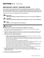
SECTION 1 | Safety
Important Safety Instructions
This manual contains important information regarding safety, operation, maintenance
and storage of this product. Before use, read and understand all cautions, warnings, instructions and product labels, plus your vehicle’s battery manufacturer’s guidelines. Failure
to do so could result in injury and / or property damage. The following safety symbols will
be used in this manual to highlight safety and information:
Warning!
Indicates possibility of physical harm to the user in case of non-compliance.
!
Caution!
Indicates possibility of damage to the equipment in case of non-compliance
i
Info
Indicates useful supplemental information.
Warning!
To reduce the risk of fire, electric shock, explosion or injury
1. Do not connect in parallel with another AC source e.g. Utility AC Distribution Wiring /
generator. This is NOT a Grid Tied Inverter!
2. Disconnect appliance plug from outlet strip or turn off the inverter before working on the
appliance. Multiple Outlet Power Strips with switches and circuit breakers only interrupt
power to the “Hot” receptacle terminals.
3. Precautions when working with batteries
•
Batteries contain very corrosive diluted Sulphuric Acid as electrolyte. Precautions should be
taken to prevent contact with skin, eyes or clothing.
•
Batteries generate Hydrogen and Oxygen during charging resulting in evolution of explosive
gas mixture. Care should be taken to ventilate the battery area and follow the battery manufacturer’s recommendations.
•
Never smoke or allow a spark or flame near the batteries.
•
Use caution to reduce the risk of dropping a metal tool on the battery. It could spark or short
circuit the battery or other electrical parts and could cause an explosion.
•
Remove metal items like rings, bracelets and watches when working with batteries and also
use caution when working with metal tools. Batteries can produce a short circuit current
high enough to melt / weld metals and thus, cause severe burn.
•
If you need to remove a battery, always remove the ground terminal from the battery first.
Make sure that all the accessories are off so that you do not cause a spark.
4. Do not make any electrical connections or disconnections in areas designated as
IGNITION PROTECTED. This includes 12VDC Power Plug (Cigarette Plug) connections and
terminal connections.
5. This is not a toy - keep away from children.
6. Do NOT insert object into the air vents.
SAMLEX AMERICA INC. | 1
SECTION 1 | Safety
!
Caution!
1. The metal chassis of the inverter and the Grounding Terminal of the NEMA5-15R outlet(s)
are internally bonded (connected) to the Negative DC Input Terminal on the inverter. In a
vehicle / boat, the Negative Terminal of the battery is bonded to vehicle chassis / boat’s hull.
Hence, the metal chassis of the inverter and the AC loads will be automatically grounded
(bonded to the vehicle chassis / boat’s hull).
2. Please ensure that the Negative DC Input Terminal on the inverter or the Battery Negative
Terminal on the battery itself is bonded to Earth Ground WHEN THE INVERTER IS USED ON
LAND.
3. The Line and Neutral Terminals of the NEMA5-15R AC outlets are isolated from its Grounding Terminal. Thus, the metal chassis of the AC loads and the metal chassis of the inverter
will also be isolated from the Line and Neutral. The Grounding Terminal of the AC outlet
is connected to the input section of the Electronic Ground Fault Protection Circuit on the
Power Circuit Board. Due to the above implementation, the voltage on the Neutral and Line
Terminals of the AC outlet with respect to the chassis of the inverter / chassis of the AC loads
will be pulsing DC voltage with average DC value of up to 50V (will read 75 VAC on AC scale
of the Voltmeter because of pulsing nature of DC voltage). DO NOT TOUCH THE NEUTRAL
TERMINAL / NEUTRAL CONDUCTORS!
4. Do not connect to AC distribution wiring where the Neutral is bonded to Ground. The
inverter will see this as abnormal condition of Ground Fault and will shut down.
5. Do not use with Positive Grounded Electrical Systems (the majority of modern automobiles,
RVs, trucks and boats use Negative Grounded Electrical Systems).
6.Observe correct polarity when connecting the DC input terminals of the inverter to the
battery. Connect Positive of the battery to the Positive input connector of the inverter and
the Negative of the battery to the Negative input terminal of the inverter. Reverse polarity
connection will result in a blown fuse and may cause permanent damage to the inverter.
Damage due to reverse polarity is not covered under warranty.
7. This inverter will not operate high wattage appliances that exceed the output power limit
or the surge power limit.
8. Do not operate this inverter if it is wet.
9. Do not install in engine compartment – please install in a well-ventilated area.
10.This inverter is not tested for use with medical devices.
2 | SAMLEX AMERICA INC.
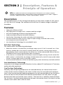
SECTION 2 | Description, Features &
Principle of Operation
i
Info For additional technical and operational information on inverters, battery
chargers and related topics, please refer to www.samlexamerica.com under "Support"
and view "Application Notes" and/or "White Papers" section.
Description
The inverter converts 12 VDC voltage from battery or from other suitable 12 VDC source
to 115V, 60 Hz AC voltage. The waveform of the of the AC output voltage is Modified
Sine Wave.
Features
• High peak efficiency of 90%
• Very high power to weight ratio - compact and light weight
• Soft Start Technology for better surge performance
• Load controlled cooling fan for better efficiency
• Cool Surface Technology for cooler and safer touch temperature
• Universal Protection circuit for low / high DC input voltage, overload / short circuit,
over temperature and Ground Fault
• Low Interference Technology for controlled RF noise
Soft Start Technology
This feature offers the following advantages:
• When the inverter is switched ON, the voltage ramps up to 115 VAC in around 2 sec. If the
load was already ON at the time of switching ON of the inverter, starting surge current
demanded by certain reactive devices like motors etc. will be reduced and there will be less
likelihood of the inverter shutting down due to overload.
• If the inverter is switched ON first and then a load with higher starting / inrush current like
SMPS / motor is switched ON, the voltage will dip momentarily and will ramp up and reduce
inrush / starting surge current in the load as above
• Similar overload reduction will be initiated during any other momentary overload condition
Low Interference Technology
Innovative circuit design and noise filtration circuitry reduce RF interference in TV picture,
audio and radio equipment
Cool Surface Technology
Normally, heat dissipating components are mounted directly on internal metal chassis
surface of the inverter and hence, the chassis surface may rise to unsafe touch-temperature. In this inverter, heat-dissipating components are not mounted directly on the chassis
of the unit but on PCB (Printed Circuit Board) mounted heat sink and, there is air gap
between the heat sink and the chassis surface. The heat sink is cooled by load-controlled
fan. As there is no direct contact between the heat sink and the chassis, the chassis surface
remains much cooler and is safer to touch.
SAMLEX AMERICA INC. | 3
SECTION 2 | Description, Features &
Principle of Operation
Load Controlled Cooling Fan
Cooling is carried out by convection and by forced air circulation by load-controlled fan.
The fan will normally be OFF and will be switched ON automatically at the following
loads:
SAM-1000-12
28 to 32 Watts
SAM-1500-12, SAM-2000-12 & SAM-3000-12
90 to 110 Watts
This will reduce energy consumption by the fan and will increase overall efficiency
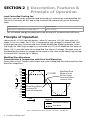
Principle of Operation
Conversion of 12 VDC from the battery / other DC source to 115 VAC takes place in 2
stages. In the first stage, the 12 VDC is converted to high voltage DC (around 160 VDC)
using high frequency switching and Pulse Width Modulation (PWM) technique. In the
2nd stage, the 160V high voltage DC is converted to 115V, 60 Hz Modified Sine Wave AC.
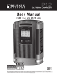
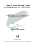
(Note: 115 V is the RMS value of the Modified Sine Wave AC voltage. The peak value of
the Modified Sine Wave AC voltage will be equal to the value of the above high voltage
of around 160V. See the Fig 2.1 below)
Modified Sine Waveform Characteristics & Comparison with Pure Sine Waveform
Please refer to Fig 2.1 below which shows one cycle of Modified Sine Wave and Pure Sine
Wave for comparison.
V+
V-
180
160
140
120
100
80
60
40
20
0
20
40
60
80
100
120
140
160
180
115 RMS
Modified Sine
Wave sits at
0V for some
time and then
rises or falls
Pure Sine Wave
crosses 0V
instantaneously
TIME
Legend
Modified Sine Wave
Sine Wave
Fig 2.1 Modified Sine Wave and Pure Sine Wave - Comparison
4 | SAMLEX AMERICA INC.
SECTION 2 | Description, Features &
Principle of Operation
The output waveform of the inverter is a Modified Sine Wave. In a Modified Sine Wave,
the voltage waveform consists of rectangular pulses that approximate sine wave pulses
of a Pure Sine Wave. The voltage rises and falls abruptly at a particular phase angle and
sits at 0 Volts for some time before changing its polarity. In a Pure Sine Wave, the voltage
rises and falls smoothly with respect to phase angle and the voltage changes its polarity
instantly when it crosses 0 Volts.
!
Caution!
Certain devices (few examples given below) may malfunction when powered from Modified Sine Wave. Check with the manufacturer of the device for suitability of powering
with Modified Sine Wave:
• Devices utilizing zero voltage crossing for timing control: Some clocks used in
consumer electronic items (will not keep accurate time)
• Devices using modulation of RF signals on AC lines during zero crossing
e.g. X-10 System for Home Automation
• Devices utilizing Triac based phase control for transformer less voltage step
down e.g.:
•
Small battery chargers for hand tools, flashlights, night-lights, shavers etc.
•
Variable motor speed control in hand tools
•
Light dimmers
•
Temperature controllers e.g. Temperature Controlled Electric Blankets
• Devices using high capacitance based voltage multipliers for generating high
voltage (will create very high surge currents) e.g.:
•
Photographic Strobe Lights
•
Laser Printers
Measuring Modified Sine-Wave Voltage with a “True Rms” Voltmeter
As mentioned above, Modified Sine Wave voltage is a type of square wave that has an RMS
(Root Mean Square) value of 115 VAC in this inverter. A general-purpose AC voltmeter is
calibrated to accurately measure the RMS value of a Pure Sine Wave and NOT of a Modified
Sine Wave. If this general-purpose voltmeter is used to measure Modified Sine Wave voltage, it will indicate a lower value (96 VAC to 104 VAC). For accurately measuring the voltage
of a Modified Sine Wave, use a voltmeter which is designed to measure “True RMS Values”
like Fluke 87, Fluke 8060A, Fluke 77 / 99, Beckman 4410 etc.
SAMLEX AMERICA INC. | 5
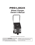
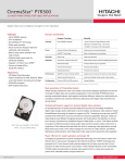
SECTION 3 | Layout
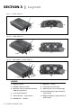
Fig. 3.1 – SAM-1000-12
8
1
11
2
2
5
6
7
10
9
3
Fig. 3.2 – SAM-1500-12
8
1
5
3
11
7
6
10
9
2
Fig 3.3 – SAM-2000-12, SAM-3000-12
8
4
1
11
3
6
2
5
6
7
10
9
LEGEND
1.ON/OFF Switch
7. RED LED - "Fault"
2. NEMA5-15R AC Outlet
8. Cooling Air Intake Slots
3. Modular Jack for Remote Control
SAM-RC (Optional)
9.Opening for Fan Air Discharge
4. 15A Circuit Breaker
5. YELLOW LED - "Input Fault"
6. GREEN LED - "Power"
6 | SAMLEX AMERICA INC.
10.Positive Battery Input Terminal
(with cover)
11.Negative Battery Input Terminal
(with cover)
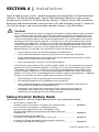
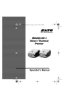
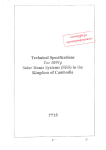
SECTION 4 | Installation
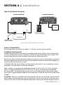
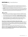
Typical Installation Diagram
FRONT OF INVERTER
BACK OF INVERTER
–
+
AC Load
Fuse
–
+
Remote Control
SAM-RC (optional)
12V Battery
Vehicle Ground
or Earth Ground
Fig 4.0. Typical Installation Diagram (front & back)
Safety of Installation
Please read safety instructions on pages 1-2 before commencing installation.
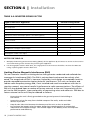
Installation Environment
For best operating results, the inverter should be placed on flat surface, such as the ground,
car floor, or other solid surface. The power cord allows easy positioning of the inverter. The
inverter should only be used in locations that meet the following criteria:
Dry- Do not allow water and/or other liquids to come into contact with the power inverter. In
all marine applications, do not install the inverter below or near the waterline and keep the
inverter away from moisture or water.
If Flooded / Wet Cell Type of battery is being used, ensure that it is not installed very close to
the battery to avoid contact with acid / acid vapors
Cool - Ambient air temperature should be between 0°C (32°F) to 25°C (77°F) for full rated
power. At higher temperature of 26°C (79°F) to 35°C (95°F), the output power should be
de-rated to 80%. Do not place the inverter on or near a heating vent or any piece of equipment, which is generating heat above room temperature. Keep the inverter away from direct
sunlight.
Ventilated - The unit is cooled by load-controlled fan. The fan will be off up to certain threshold of power and automatically switch on thereafter. The fan sucks cool air in from the ventilation slots on the AC outlet side and discharges hot air out of the fan opening (9) on the DC
SAMLEX AMERICA INC. | 7
SECTION 4 | Installation
Input Terminal side. Keep the areas surrounding the inverter clear by at least 10 cm to ensure
free air circulation around the unit. Ensure that the ventilation slots and fan opening on the
sides are not blocked. Do not place items on or over the inverter during operation.
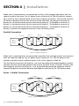
Mounting Orientation
Two (2) flanges on the bottom with 2 mounting slots each are provided for mounting.
If the inverter is required to be mounted on a vertical surface like a wall, please ensure that
the fan axis is horizontal as shown in Fig 4.1(a).
The DC input side has larger ventilation openings (9) for fan airflow. Mounting with the fan
side facing up or down as shown in Figs 4.1(b) or 4.1(c) is NOT permitted due to safety considerations. If mounted as in Fig 4.1(b), metallic or other conductive object(s) may accidentally fall
inside the unit through the fan ventilation openings, and create hazardous condition resulting
from short circuit of internal high voltage section(s). If mounted as in Fig 4.1(c), hot / molten
material from damaged internal portion of the unit due to malfunction may fall on combustible material on the floor and may create fire hazard.
Fig 4.1
Mounting Orientation
on Wall
(a)
(b)
(c)
Remote Control Model SAM-RC (optional)
An optional wired Remote Control Model SAM-RC is available. It comes with 3M, RJ-45 cable. It can
be used to Switch ON and switch OFF the inverter and also displays the operational status of the
inverter using colored LEDs. Plug the Remote Control Modular Plug into the Modular Jack
(3 - Fig 3.1, 3.2, 3.3). See typical installation diagram at Fig 4.0, page 7. Refer to separate Owner's
Manual provided with the Remote for further details of the remote's operation.
DC Side Connections
See typical installation diagram at Fig 4.0, page 7.
General Information
1. The metal chassis of the inverter and the Grounding Terminal of the NEMA5-15R outlet(s)
are internally bonded (connected) to the Negative DC Input Terminal on the inverter. In a
vehicle / boat, the Negative Terminal of the battery is bonded to vehicle chassis / boat’s hull.
Hence, the metal chassis of the inverter and the AC loads will be automatically grounded
(bonded to the vehicle chassis / boat’s hull).
2. Please ensure that the Negative DC Input Terminal on the inverter or the Battery Negative
Terminal on the battery itself is bonded to Earth Ground WHEN THE INVERTER IS USED ON
LAND.
8 | SAMLEX AMERICA INC.
SECTION 4 | Installation
3. Do not use with Positive Grounded Electrical Systems (the majority of modern automobiles,
RVs, trucks and boats use Negative Grounded Electrical Systems).
4.Observe correct polarity when connecting the DC input terminals of the inverter to the
battery. Connect Positive of the battery to the Positive input connector of the inverter and
the Negative of the battery to the Negative input terminal of the inverter. Reverse polarity
connection will result in a blown fuse and may cause permanent damage to the inverter.
Damage due to reverse polarity is not covered under warranty.
Requirements of DC Input Power Source
Approx. DC Input Current required by Inverter = Power consumed by the AC Load in
Watts ÷ 10.
DC input currents at Continuous Rated Power Output are shown (Table 4.1 below):
Table 4.1 DC Input Current
Model
Rated Input Current
SAM-1000-12
100A
SAM-1500-12
150A
SAM-2000-12
200A
SAM-3000-12
300A
12VDC input to the inverter should be fed from a 12V Battery System or from a 12.5VDC
to 15VDC Regulated DC Power Supply. If a DC Power Supply is used, its output current capacity should be more than 2 times the maximum DC input current drawn by the inverter. Further explanation of operation is based on DC input power from a 12V battery. It is
recommended that Deep Cycle Type Batteries are used. For detailed technical information
on types, construction, specifications, sizing, connections and charging / discharging of Lead Acid Batteries, please read online White Paper titled “Batteries, Chargers and
Alternators” at www.samlexamerica.com under Support/White Papers.
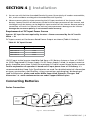
Connecting Batteries
Series Connection
Cable “A”
24V
Inverter/
Charger
Battery 4
Battery 3
Battery 2
Battery 1
6V Battery
6V Battery
6V Battery
6V Battery
Cable “B”
Cable “A”
12V
Inverter/
Charger
Battery 1
Battery 2
12V Battery
12V Battery
Battery 3
Fig. 4.2 Series Connection
12V Battery
Battery 4
SAMLEX AMERICA INC. | 9
12V Battery
SECTION 4 | Installation
When two or more batteries are connected in series, their voltages add up but their Ah
capacity remains the same. Fig. 4.2 above shows 4 pieces of 6V, 200 Ah batteries connected in series to form a battery bank of 24V with a capacity of 200 Ah. The Positive terminal
Battery
2
Battery
4
Battery 1terminal of
of Battery 4 becomes the
terminal
ofBattery
the3 24V bank.
The
Negative
CablePositive
“A”
Battery 4 is connected to the Positive terminal of Battery 3. The Negative terminal of
Battery 3 is connected to the Positive terminal of Battery 2. The Negative terminal of
24V
6V Battery
6V Battery
6V Battery
6V Battery
Inverter/
Battery 2 is connected
to the Positive terminal of Battery 1. The Negative terminal of
Charger
Battery 1 becomes the Negative terminal of the 24V battery bank.
Parallel Connection
Cable “B”
Cable “A”
12V
Inverter/
Charger
Cable “A”
24V
Inverter/
Charger
Cable “B”
Battery 1
Battery 2
12V Battery
12V Battery
Battery 4
Battery 3
6V Battery
6V Battery
Battery 3
Battery 4
12V Battery
12V Battery
Battery 2
Battery 1
6V Battery
6V Battery
Fig.12V
4.3
Parallel
Connection
String
1
12V String 2
Cable “B”
When two or more batteries areBattery
connected
in
parallel,
their
remains
the same but
1
Battery
2
Battery voltage
3
Battery 4
their Ah capacities addCable
up.“A”Fig. 4.3
above
shows
of 12V,
100 AH
batteries
conBattery
1
Battery4
2 pieces Battery
3
Battery
4
Cable “A”
nected in parallel to form a battery bank of 12V with a capacity of 400 Ah.
The four Positive
terminals of Batteries 1 to 4 are paralleled (connected together) and this
12V
12V
6V
6V
6V
6V
12VBattery
Battery
12VBattery
Battery
12VBattery
Battery
12VBattery
Battery
Inverter/
Inverter/
common Positive
connection becomes the Positive terminal of the 12V bank. Similarly, the
Charger
Charger
four Negative terminals of Batteries 1 to 4 are paralleled (connected together) and this
common Negative connection
becomes the Negative terminal of the 12V battery bank.
Cable “B”
Cable “B”
Series – Parallel Connection
12V String 1
12V String 2
Battery 1
Battery 2
Battery 3
Battery 4
6V Battery
6V Battery
6V Battery
6V Battery
Cable “A”
12V
Inverter/
Charger
Cable “B”
Fig. 4.4 Series-Parallel Connection
10 | SAMLEX AMERICA INC.
SECTION 4 | Installation
Figure 4.4 above shows a series – parallel connection consisting of four 6V, 200 Ah batteries
to form a 12V, 400 Ah battery bank. Two 6V, 200 Ah batteries, Batteries 1 and 2 are connected in series to form a 12V, 200 Ah battery (String 1). Similarly, two 6V, 200 Ah batteries,
Batteries 3 and 4 are connected in series to form a 12V, 200 Ah battery (String 2). These two
12V, 200 Ah Strings 1 and 2 are connected in parallel to form a 12V, 400 Ah bank.
!
Caution!
When 2 or more batteries / battery strings are connected in parallel and are then connected
to an Inverter Charger (See Figs. 4.3 and 4.4 given above), attention should be paid to the
manner in which the Inverter Charger is connected to the battery bank. Please ensure that
if the Positive output cable of the Inverter Charger (Cable “A”) is connected to the Positive
battery post of the first battery (Battery 1 in Fig. 4.3) or to the Positive battery post of the
first battery string (Battery 1 of String 1 in Fig. 4.4), then the Negative output cable of the
Inverter Charger (Cable “B”) should be connected to the Negative battery post of the last
battery (Battery 4 as in Fig. 4.3) or to the Negative Post of the last battery string (Battery 4 of
Battery String 2 as in Fig. 4.4). This connection ensures the following:
•
The resistances of the interconnecting cables will be balanced.
•
All the individual batteries / battery strings will see the same series resistance.
•
All the individual batteries will charge at the same charging current and thus, will be
charged to the same state at the same time.
•
None of the batteries will see an overcharge condition.
If the Positive output cable of the Inverter Charger (Cable “A”) is connected to the Positive
battery post of the first battery (Battery 1 in Fig. 4.3) or to the Positive battery post of the
first battery string (Battery 1 of String 1 in Fig. 4.4), and the Negative output cable of the
Inverter Charger (Cable “B”) is connected to the Negative battery post of the first battery
(Battery 1 as in Fig. 4.3) or to the Negative Post of the first battery string (Battery 1 of Battery
String 1 as in Fig. 4.4), the following abnormal conditions will result:
•
The resistances of the connecting cables will not be balanced.
•
The individual batteries will see different series resistances.
•
All the individual batteries will be charged at different charging current and thus,
will reach fully charged state at different times.
•
The battery with lower series resistance will take shorter time to charge as
compared to the battery which sees higher series resistance and hence, will
experience over charging and its life will be reduced.
Sizing Inverter Battery Bank
The following basic rules are used to determine the size of the battery bank:
•
Active Power in Watts (W) =
Voltage in Volts (V) x Current in Amperes (A) x Power Factor....................... Formula 1
•
For an inverter running from a 12V battery system,
the DC current required from the 12V batteries is the
AC power delivered by the inverter to the load in Watts (W)
divided by 10...................................................................................................... Formula 2
•
Energy required from the battery =
DC current to be delivered (A) x time in Hours (H)......................................... Formula 3
•
As a Rule of Thumb, Ah capacity of the batteries required =
2 x Energy required from the battery.............................................................. Formula 4
SAMLEX AMERICA INC. | 11
SECTION 4 | Installation
An example of this calculation for a 12V inverter is given below:
Let us say that the total continuous AC Watts delivered by the 12V inverter = 1500W.
Then, using Formula 2 above, the DC current to be delivered by the 12V batteries =
1500W ÷10 = 150 Amperes.
Next, the energy required by the load in Ampere Hours (Ah) is determined:
For example, if the load is to operate for 3 Hours, then as per Formula 3 above, the energy
to be delivered by the 12V batteries = 150 Amperes × 3 Hours = 450 Ampere Hours (Ah).
Finally, as per Rule of Thumb at Formula 4, the Ah capacity of the batteries should be
twice the energy required by the load in Ah = 450 Ah x 2 = 900 Ah.
DC Input Power Terminals
Custom made DC input terminals using M9 Nut / Bolt arrangement have been provided
for connecting DC input cables (10, 11 in Fig 3.1 to 3.3). The terminals are protected by
plastic covers.
Important Wiring/Cabling Information
Although wires and cables are good conductors of electric current, they do have some
resistance, which is directly proportional to the length and inversely proportional to the
thickness (diameter) i.e. resistance increases in thinner and longer wires. Current flowing
through resistance produces heat. Cables and wires are covered with insulating material
that can withstand a specified temperature of the conductor under specified conditions.
To ensure that the insulation is not damaged due to excessive overheating, each wire size
has a maximum allowable current carrying capacity called "Ampacity" which is specified
by NEC Table 31.15 (B) (17). Further, NEC also specifies that wire size should be based on
Ampacity - 1.25 times the rated current flow.
Resistance of wires and cables produces another undesirable effect of voltage drop. Voltage drop is directly proportional to the resistance and the value of current flow. Voltage
drop produces loss of power in the form of heat. In addition, excessive voltage drop from
the battery to the inverter may prematurely shut down the inverter due to activation of
the Low Input Voltage Protection Circuitry of the inverter (10.5 ± 0.3V). DC cables should
be sized to ensure maximum voltage drop is limited to less than 5%.
Effects of low voltage on common electrical loads are given below:
Lighting Circuits – Incandescent and Quartz/Halogen: Loss in light output because the
bulb not only receives less power, but the cooler filament drops from white-hot towards
red-hot, emitting much less visible light.
Lighting Circuits – Fluorescent: Voltage drop causes an early proportional drop in
light output.
AC Induction Motors: These are commonly found in power tools, appliances, etc. They
exhibit very high surge demands when starting. Significant voltage drop in these circuits
may cause failure to start and possible motor damage.
12 | SAMLEX AMERICA INC.
SECTION 4 | Installation
Requirement of Fuse in Battery Connection
A battery is a very large source of current. If there is a short circuit along the length of
the cables that connect the battery to the inverter, thousands of Amperes of current can
flow from the battery to the point of shorting and that section of the cable will overheat,
the insulation will melt and is likely to cause fire. To prevent occurrence of hazardous
conditions under short circuit, fuse with Ampere rating ≥ the maximum continuous current drawn by the inverter but ≤ the Ampacity of the connecting cable should be used
in the battery connection. The fuse should be fast acting Class-T or Marine Rated Battery
Fuse Type MRBF. Rating of fuse is shown in Table 4.2 below. The fuse should be installed
as close to the Battery Positive terminal as possible, preferably within 7”. Please note that
this fuse is required to protect the cable run from the battery to the inverter against short
circuit. The inverter has its own internal DC side fuse(s) for internal DC side protection.
Making DC Side Connections
Recommended cable and fuse sizes for connecting battery are given in Table 4.2. The
maximum current for cable sizing / fuse rating has been considered at 1.25 times rated
continuous current draw at the rated output power.
Table 4.2 Recommended Cable and Fuse Sizes for Battery Connection
Model No.
Rated
DC Input
Current
Cable Size1
(Ampacity)
Max
Fuse
Size2
Distance between
Inverter,
Battery and % Voltage
Drop3
3 ft.
6 ft.
10 ft.
Samlex
Fuse
(Optional)
Samlex
Cable +
Fuse Kit
(Optional)
SAM-1000-12
100A
AWG#4
(160A)
100 to
150A
1.2%
2.4%
4.0%
DC-FA-100
DC-1000-KIT
SAM-1500-12
150A
AWG#2
(215A)
200A
1.2%
2.3%
3.8%
DC-FA-200
DC-2000-KIT
SAM-2000-12
200A
AWG#2/0
(329A)
300A
0.8%
1.5%
2.5%
DC-FA-300
DC-2500-KIT
SAM-3000-12
300A
AWG#4/0
(446A)
400A
0.7%
1.4%
2.4%
DC-FA-400
DC-3500-KIT
NOTES:
1. Cable Size
• As per NEC, size is based on Ampacity ≥ 1.25 times the rated DC Input Current
• Conductor / Insulation rating : 105 °C
2. Fuse Size
• Type: Class-T or Marine Rated Battery Fuse (MRBF)
• The rating of the fuse should not exceed the Ampacity of the Cable
3. Distance between Inverter and Battery and % Voltage Drop
• Voltage drop is calculated based on length of cable = 2 x Distance to consider total length of Positive
and Negative cables
• % drop is calculated with respect to rated battery voltage of 12.5V
SAMLEX AMERICA INC. | 13
SECTION 4 | Installation
!
Caution!
• Please ensure that the recommended external fuse specified in Table 4.2 above
(Fuse is not supplied) is installed in series with the Positive cable and is as close to
the Battery (+) terminal as possible (preferably within 7”).
•
Please ensure that all the connections are tight. Loose connections may cause
overheated wires and melted insulation.
AC Side Connections
See typical installation diagram at Fig 4.0, page 7.
General Information
1. The metal chassis of the inverter and the Grounding Terminal of the NEMA5-15R outlet(s)
are internally bonded (connected) to the Negative DC Input Terminal on the inverter. In a
vehicle / boat, the Negative Terminal of the battery is bonded to vehiclchassis / boat’s hull.
Hence, the metal chassis of the inverter and the AC loads will be automatically grounded
(bonded to the vehicle chassis / boat’s hull).
2. The Line and Neutral Terminals of the NEMA5-15R AC outlets are isolated from its Grounding Terminal. Thus, the metal chassis of the AC loads and the metal chassis of the inverter
will also be isolated from the Line and Neutral. The Grounding Terminal of the AC outlet
is connected to the input section of the Electronic Ground Fault Protection Circuit on the
Power Circuit Board. Due to the above implementation, the voltage on the Neutral and Line
Terminals of the AC outlet with respect to the chassis of the inverter / chassis of the AC loads
will be pulsing DC voltage with average DC value of up to 50V (will read 75 VAC on AC scale
of the Voltmeter because of pulsing nature of DC voltage). DO NOT TOUCH THE NEUTRAL
TERMINAL / NEUTRAL CONDUCTORS!
Connecting AC Loads
AC output of the inverter is fed through NEMA5-15R outlets. Details are given in the Table 4.3
below:
TABLE 4.3 Details AC Output Connections
Model No.
Rated Output
Power1 of
the Inverter
Rated Output
Current
(Rated Output
Power ÷ 115VAC)
NEMA5-15R2
Outlet
(2, Figs 3.1, 3.2)
NEMA5-15R2
outlet
(2, Fig 3.2) each
with 15A Breaker
(4, Fig 3.2)
SAM-1000-12
1000 VA1
-
8.7A
2
SAM-1500-12
1
1500VA
13.0A
2
-
SAM-2000-12
2000VA3
17.4A3
-
3
SAM-3000-12
3000VA3
26.0A3
-
3
14 | SAMLEX AMERICA INC.
SECTION 4 | Installation
Notes for Table 4.3
1. Power shown in the Table above is the Apparent Power in Volt Amps (VA). Active Power in Watts = Apparent Power in VA x Power Factor of the AC load. For resistive type of AC loads, the Power Factor is 1
and for these types of loads, Apparent Power in “VA” = Active Power in “Watts”. Power ratings shown in
the Specifications on page 24 are applicable for Resistive Load and hence, Watts = VA 2. Each NEMA5-15R outlet is rated at maximum current capacity of 15A and power of 1725VA at 115VAC
3. CAUTION! For SAM-2000-12 and SAM-3000-12, the full rated power cannot be drawn from 1 NEMA5-15R
outlet as each outlet is rated for only 15A (1725VA) and is protected by 15A breaker. If a single load rated
at > 1725VA is required to be powered, output from 2 NEMA5-15 outlets should be paralleled and then
fed to this load. If a load > 1725VA / 15A is powered from a single breaker protected NEMA5-15R outlet,
its 15A breaker will trip (pops out) and will have to be reset manually (pushed in).
!
Caution!
1.
Do not connect to AC distribution wiring where the Neutral is bonded to Ground.
The inverter will see this as abnormal condition of Ground Fault and will shut down.
2.
The AC output from this inverter should NOT be connected in parallel with another
AC source like grid / generator / another inverter - SEVERE DAMAGE WILL OCCUR!
3.
If the AC output from this inverter is required to be fed to an AC Distribution Panel /
Sub Panel for backup AC power, a suitable Transfer Switch like Samlex America
Transfer Switch Model No. STS-30 should be used. The Transfer Switch will prevent
parallel operation of AC output of this inverter with the other AC source.
Sizing Chart for Typical Loads that Require High Starting Surge
The manufacturers’ specifications for power rating of appliances and devices indicate only
the Running Power required. The Surge Power required by some specific types of devices
as explained above has to be determined by actual testing or by checking with the manufacturer. This may not be possible in all cases and hence, can be guessed at best, based on
some general Rules of Thumb.
Table 4.4 lists some common loads that require high surge power on start up. A “Sizing Factor” has been recommended against each which is a Multiplication Factor to be
applied to the rated running Watt rating of the load to arrive at the Continuous Power
Rating of the inverter (Multiply the running Watts of the device/ appliance by the Sizing
Factor to arrive at the size of the inverter).
SAMLEX AMERICA INC. | 15
SECTION 4 | Installation
TABLE 4.4: INVERTER SIZING FACTOR
Type of Device or Appliance
Inverter Sizing Factor1
Air Conditioner / Refrigerator / Freezer (Compressor based)
5
Air Compressor
4
Sump Pump / Well Pump / Submersible Pump
3
Dishwasher / Clothes Washer
3
Microwave (where rated output power is the cooking power)
2
Furnace Fan
3
Industrial Motor
3
Portable Kerosene / Diesel Fuel Heater
3
Circular Saw / Bench Grinder
3
Incandescent / Halogen / Quartz Lamps
3
Laser Printer / Other Devices using Quartz Lamps for heating
4
2
Photographic Strobe / Flash Lights
4
NOTES FOR TABLE 4.4
1. Multiply the Running Active Power Rating {Watts} of the appliance by this Factor to arrive at the Continuous Power Rating of the inverter for powering this appliance.
2.For Photographic Strobe / Flash Unit, the surge power of the inverter should be > 4 times the Watt Sec
rating of photographic strobe / flash unit.
Limiting Electro-Magnetic Interference (EMI)
This unit contains internal switching devices that generate conducted and radiated electromagnetic interference (EMI). The EMI is unintentional and cannot be entirely eliminated. The magnitude of EMI is, however, limited by circuit design to acceptable levels to
provide reasonable protection against harmful interference. This unit can conduct and
radiate radio frequency energy and, if not installed and used in accordance with the instruction manual, may cause harmful interference to radio communications. The effects of
EMI will also depend upon a number of factors external to the unit like proximity of the
unit to the EMI receptors, types and quality of connecting wires and cables etc. EMI due to
factors external to the unit may be reduced as follows:
-
Ensure that the unit is firmly grounded to the ground system of the building or
the vehicle.
-
Locate the unit as far away from the EMI receptors like radio, audio and video
devices as possible.
-
Keep the DC side wires between the battery and the unit as short as possible.
-
Do not keep the battery wires far apart. Keep them taped together to reduce their
inductance and induced voltages. This reduces ripple in the battery wires and improves
performance and efficiency.
16 | SAMLEX AMERICA INC.
SECTION 4 | Installation
-
Shield the DC side wires with metal sheathing / copper foil /braiding: - Use coaxial shielded
cable for all antenna inputs (instead of 300 ohm twin leads)
- Use high quality shielded
cables to attach audio and video devices to one another.
-
Limit operation of other high power loads when operating audio/video equipment.
Buzzing Sound in Audio Systems
Some inexpensive sound stereo systems and “Boom Boxes” may emit a buzzing sound
from their speakers when operated from this unit. This is likely to occur because the
power supply in the electronic device does not adequately filter higher frequency harmonics generated by Modified Sine Wave produced by this unit. The solution is to use
higher quality sound system that incorporates higher quality of interference suppression
in its power supply.
SAMLEX AMERICA INC. | 17
SECTION 5 | Operation
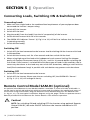
Connecting Loads, Switching ON & Switching OFF
Connecting Loads
1. Make sure that single load or the combined load requirement of your equipment does
not exceed the inverter's output rating.
2. Switch OFF the inverter.
3. Switch OFF the load.
4. Plug the cord(s) from the load(s) into the AC receptacle(s) of the inverter
5. Switch ON the inverter. Wait for a few seconds.
6. The GREEN LED indicator "Power" (6, Fig 3.1 to 3.3) will be lit to indicate that the inverter
is operating normally.
7. Switch ON the load(s).
Switching ON
1. Switch OFF the load connected to the inverter. Avoid switching ON the inverter with load
in ON condition.
2. Switch ON the inverter, wait for a few seconds and then switch ON the load.
3. When using high capacitive loads with inadequate inrush current limiting like cheaper
quality of Compact Flourescent Lamps (CFL) etc., wait for 10 seconds before switching ON
such loads. If the inverter is switched ON with these types of loads in ON condition, the inverter may shut down or the loads may not switch ON. Sometimes, adding a small resisitive
load (like incandescent lamp) in parallel with such devices may prevent such shut down.
Switching OFF
1. Switch OFF the load connected to the inverter
2. Switch OFF the inverter. Please note that on switching OFF, the GREEN LED "Power"
(6, Fig. 3.1, 3.2, 3.3) will extinguish slowly.
Remote Control Model SAM-RC (optional)
An optional wired Remote Control Model SAM-RC is available. It comes with 3M, RJ-45 cable. It
can be used to Switch ON and switch OFF the inverter and also displays the operational status of
the inverter using colored LEDs. Plug the Remote Control Modular Plug into the Modular Jack
(3 - Fig 3.1, 3.2, 3.3). See typical installation diagram at Fig 4.0, page 7. Refer to separate Owner's
Manual provided with the Remote for further details of the remote's operation.
!
Caution!
Note: For switching ON and switching OFF the inverter using optional Remote
Control SAM-RC, the main ON/OFF Switch on the inverter should be in OFF
position.
18 | SAMLEX AMERICA INC.
SECTION 5 | Operation
If the ON/OFF Switch on the inverter is left in ON position, the inverter cannot be
switched OFF using Remote Control. The Remote Control will, however, continue
to display the Status of Operation.
Note: When optional Remote Control SAM-RC is used to switch OFF the unit, the
GREEN LED "Power" (6-Fig 3.1, 3.2 & 3.3) takes 30 to 45 secs to extinguish if there is no
load connected to the inverter. If a load is present, the LED will extinguish within a very
short time.
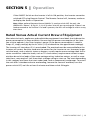
Rated Versus Actual Current Draw of Equipment
Most electrical tools, appliances and audio/video equipment have labels that indicate the
power consumption in Amps or Watts. Be sure that the power consumption of the item
you wish to operate is less than inverter's power (if the power consumption is rated in
Amps AC, simply multiply by the AC Volts (115) to determine the approximate wattage).
The inverter will shut down if it is overloaded. The overload must be removed before the
inverter will restart. Resistive loads are the easiest for the inverter to run. However, larger
resistive loads, such as electric stoves or heaters, usually require more wattage than the inverter can deliver. Inductive loads, such as TV's and stereos, require more current to operate than do resistive loads of the same wattage rating. Induction motors, as well as some
televisions, may require 2 to 6 times their wattage rating to start up. The most demanding
in this category are those that start under load, such as compressors and pumps. To restart
the unit after a shutdown due to overloading, remove the cause of overload, turn the
power switch OFF, wait for at least 3 minutes and then switch ON again.
SAMLEX AMERICA INC. | 19
SECTION 6 | Protections Monitoring
& Trouble-Shooting
NOTE: Please refer to Table 6.1 for status of monitoring LEDs and Buzzer for various
protections / operational conditions explained below.
Over Temperature Protection
The unit is cooled by load-controlled fan. In case the fan fails or if the cooling is inadequate due to higher ambient temperature or restricted airflow, the temperature of
hot spot inside the inverter will exceed the safe temperature threshold of 88°C to 115°C
and the unit will automatically shut down. Yellow LED "Input Fault" will be ON & Green
LED "Power" will be OFF. The unit will reset automatically on cooling down 10°C to 15°C
below threshold.
Low DC Input Voltage Protection
This condition is not harmful to the inverter but could damage the 12 v battery. The inverter automatically shuts down when input voltage drops to 10.5 ± 0.3V. Yellow LED "
Input Fault" will be ON, Green LED "Power" will be OFF and buzzer alarm will be sounded. It will reset automatically when input voltage is restored to > 11.5V.
High DC Input Voltage Protection
The inverter will automatically shut down when the input voltage exceeds 15.5 V± 0.2V.
Input voltage exceeding 16 volts could damage the inverter. Yellow LED "Input Fault" will
be ON and Green LED "Power" will be OFF. Auto-reset at < 15.5V ± 0.2V.
Overload / Short Circuit / Ground Fault Protection
The inverter will automatically shut down due to (a) short circuit conditions, (b) when
the continuous / surge power exceeds rated watts and, (c) Ground Fault. The Red LED
"Overload" will be ON and Green LED "Power" will also be ON. The unit will latch in shut
down condition. To reset, switch off the on/off switch, wait for 3 minutes and switch
on again.
In models SAM-2000-12 and SAM-3000-12, if load with power draw > 1725 VA/15A is
connected to 1 NEMA5-15R outlet, the 15A breaker on top of that receptacle will trip
(pop out). Reset manually (push in).
i
Info
Some high capacitive loads like Compact Fluorescent Lamps (cfl) or Switched Mode Power
Supply (smps) will draw very high inrush current due to very fast voltage rise of the square
wave nature of the Modified Sine Wave and shut down the inverter. Try using a small resistive
load in parallel to reduce high inrush current and prevent overloading.
20 | SAMLEX AMERICA INC.
SECTION 6 | Protections Monitoring
& Trouble-Shooting
Low Input Voltage Buzzer Alarm
A buzzer alarm will sound when the voltage at the input terminals of the inverter drops
to 10.8V ± 0.3V. This is an indication that either the battery terminal voltage has dropped
due to its discharged condition and needs to be re-charged or there is an excessive voltage drop across the wires connecting the inverter to the battery (due to use of thinner
and longer length of wires that will produce higher voltage drop at higher loads or due
to loose connections). The user should stop operation of the electronic device at this time
since the inverter will shut down automatically shortly thereafter, when the input voltage
at the inverter further drops to 10.5V ± 0.3V. In case the alarm is due to the discharged
condition of the battery, start your engine to recharge the battery / use an appropriate
battery charger.
i
Info
It is normal for the alarm to sound while the unit is being connected to or disconnected from the DC power source. This is not indicative of a problem.
Ground Fault Protection - General
Due to loss of insulation as a result of aging of insulating materials, accident or malfunction, voltage source inside an electrical device can get connected to its metal chassis. If
the energized metal chassis is touched by a person standing on Earth Ground (considered
to be at 0V), the person will get a shock due to current leaked through the body to Earth
Ground (called Leakage Current). Such condition is called “Ground Fault”. As this Leakage Current is diverted to Earth Ground, it does not return to the electrical power source
supplying the ac device. Severity of electrical shock will depend upon the value of the
fault voltage on the metal chassis and the impedance in the current path to Earth Ground,
primarily the impedance of the human body (100 kΩ when dry and 1 kΩ when wet).
Human body can tolerate leakage current of up to 5mA for 15 to 30 msec.
Ground fault protection in this inverter is provided as follows:
• The Line and Neutral terminals of the ac outlet are isolated from its grounding terminal.
Thus, the metal chassis of the ac loads will also be isolated from the Line and Neutral.
• The grounding terminal of the ac outlet is connected to the input section of the Electronic
Ground Fault Protection Circuit on the power circuit board.
• Due to the above implementation, the Neutral voltage will be pulsing DC voltage with
average DC value of up to 50VDC with respect to the metal chassis of the ac loads / metal
chassis of the inverter (will read 75 VAC on the AC scale of the Voltmeter because of pulsing nature of DC Voltage). Similarly, the Line voltage will also be up to 75v with respect to
the metal chassis of the ac loads / metal chassis of the inverter . Do not touch the Line /
Neutral!
• If the metal chassis of the load develops a Ground Fault condition, up to 75V will be fed to
the Electronic Ground Fault Protection Circuit and the ac output of the inverter will shut
SAMLEX AMERICA INC. | 21
SECTION 6 | Protections Monitoring
& Trouble-Shooting
down. Red LED "Overload" will be ON and Green LED "Power" will also be ON. The unit will
latch in shutdown condition. To reset, switch OFF the ON/OFF switch, wait for 3 minutes and
switch ON again.
• Ground Fault protection will also operate if the neutral and ground of the ac output of the
inverter are connected (bonded) intentionally like in Service Entrance / Load Center for ac
distribution wiring.
!
Caution!
Connecting to utility AC distribution wiring with Neutral to Ground connection (bond) is not permitted. In AC utility distribution wiring, the Neutral conductor is connected (bonded) to the Equipment
Grounding Conductor at the Load Center / Service Entrance. Both these conductors are then bonded
to the Earth Ground (Ground Rod). Thus, if the output of the inverter is connected to the utility ac
distribution wiring, it will see a Neutral to Ground connection and the inverter will trip due to
activation of the Ground Fault Protection Circuit as explained above.
Failure to Start Some Devices on Load
Some high capacitance loads like Compact Fluorescent Lamp (cfl) or Switched Mode
Power Supply (smps) will shut down the inverter under overload condition if the inverter
is switched on with these loads in on condition. However, if these loads are switched
off first and switched on only after around 10 sec after the inverter is switched on (as
already recommended under switching on procedure), the inverter may not shut down.
Hence, do not switch on the inverter with such loads in on condition.
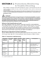
Monitoring of Operational Status & Protections
Normal / abnormal behavior can be monitored by observing Green LED (6, Power), Yellow
LED (5, Input Fault), Red LED (7, Fault) and Buzzer. Details are given in Table 6.1 below:
Table 6.1 Protections and Monitoring
Operating
Condition/
Protection
Threshold/
Reason
GREEN
LED (6,
Power)
YELLOW
LED (5,
Input
Fault)
RED
LED (7,
Fault)
Buzzer
Remedy/Reset
Normal
-
ON
OFF
OFF
OFF
-
Low DC Input
Alarm
10.8V ± 0.3V
ON
OFF
OFF
ON
Check battery voltage and
input voltage drop.
Auto reset when voltage
> 10.5 V ± 0.3V.
No Output
due to Low DC
Input Voltage
shutdown
10.5V ± 0.3V
OFF*
ON
OFF
ON
Check battery voltage and
input voltage drop.
No output due
to High DC
Input Voltage
Shut Down
15.5 ± 0.2V
Auto reset when voltage
rises to >11.5V.
22 | SAMLEX AMERICA INC.
OFF*
ON
OFF
OFF
Check charger voltage.
Auto reset when voltage
< 15.5V.
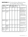
SECTION 6 | Protections Monitoring
& Trouble-Shooting
Operating
Condition/
Protection
Threshold/
Reason
GREEN
LED (6,
Power)
YELLOW
LED (5,
Input
Fault)
RED
LED (7,
Fault)
Buzzer
Remedy/Reset
No Output
due to High
Temperature
Shut Down
Internal hot
spot > 88°C
to 115°C
OFF*
ON
OFF
OFF
Check ambient temperature, fan and loss of cool
replacement air .
Auto reset when hot spot
cools down 10°C to 15°C
below the threshold.
No output due
to Over Load
Shut Down
Output power
is > Continuous / Surge
Rating
ON
OFF
ON
OFF
Check starting surge rating
of load. If happens with
low power CFL or SMPS, try
adding small resistive load.
If happens when inverter
is switched ON with high
capacitance load already in
ON condition, try switching
ON the load 10 sec after the
inverter has been switched
ON.
Manual Reset. Unit will latch
in shut down condition. To
reset, switch OFF the On/
Off Switch, wait for 3 minutes and switch ON again.
No output due
to Ground Fault
Shut Down
Neutral or
Line connected to
Ground
ON
OFF
ON
OFF
Check if there is Neutral to
Ground bond or Ground
Fault.
No output
No DC Input
Voltage due
to Blown DC
Input Fuse
OFF
OFF
OFF
OFF
Check fuse in the 12V battery input line.
For
SAM-2000-12,
SAM-3000-12:
No output
from outlet to
which load is
connected
15A breaker
on top of the
outlet has
tripped due to
load > 1725
VA/15A
ON
OFF
OFF
OFF
Remove the load and reset
the breaker (push in).
Manual Reset. Unit will latch
in shut down condition. To
reset, switch OFF the On/
Off Switch, wait for 3 minutes and switch ON again.
Ensure load connected to 1
outlet is < 1725 VA/15A.
Use 2 outlets in parallel if
load is > 1725 VA.
* On activation of protection, the Green LED will start dimming slowly and will extinguish after some time.
SAMLEX AMERICA INC. | 23
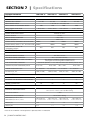
SECTION 7 | Specifications
INVERTER PARAMETER
SAM-1000-12
SAM-1500-12
SAM-2000-12
SAM-3000-12
INPUT
Battery System Voltage
12 VDC
12 VDC
12 VDC
12 VDC
Nominal Input Voltage
12.5 VDC
12.5 VDC
12.5 VDC
12.5 VDC
Input Voltage Range
> 10.5 VDC to < 15.0 (± 0.5) VDC
Input Current at Continuous Power
Input Current at No Load
100A
150A
200A
300A
0.5 to 0.6A
0.65 to 0.75A
0.75 to 0.85A
0.85 to 0.95A
OUTPUT
Output Voltage Wave Form
Modified Sine Wave
Output Voltage
115 VAC
OUTPUT VOLTAGE REGULATION
+ 10% / - 0%
OUTPUT FREQUENCY
60 Hz ± 5%
Output Power, Continuous (Resistive Load)
1000W
1500W
2000W
3000W
Output Power, Surge (<1 Sec., Resistive Load)
2000W
3000W
4000W
6000W
90%
90%
90%
Peak Efficiency (at 50% of
Continuous Power)
90%
PROTECTIONS
Low Input Voltage Alarm
YES. 10.8 VDC ± 0.3 VDC
Low Input Voltage Shutdow
10.5 VDC ± 0.3 VDC
High Input Voltage Shutdown
YES. > 15.5 VDC ± 0.2 VDC
YES. (Latches in shutdown condition. Manual reset by
switching OFF and switching ON the ON/OFF Switch)
Overload and ground fault Shut Down
Over Temperature Shutdown
Internal Hot Spot 88°C - 115°C. Auto-reset when cools down by 10°C to 15°C
COOLING FAN, Load Controlled, On at:
28 to 32W
GROUND FAULT PROTECTION
Yes. Shutdown.
DC INPUT FUSE, 32V
120A (4 x 30A)
90 to 110W
Yes. Shutdown.
240A (8 x 30A)
90 to 110W
Yes. Shutdown.
350A (10 x 35A)
90 to 110W
Yes. Shutdown.
480A (16 x 30A)
CONNECTIONS
DC Input CONNECTIONS
Nut & Bolt, M9
AC Output - No. of NEMA5-15R REceptacles
REMOTE CONTROL PORT
2
2
3*
3*
YES
YES
YES
YES
GENERAL
0°C to 25°C / 32°F to 77°F at 100% loading;
26°C to 35°C / 78.8°F to 95°F at 80% loading
Operating Temperature Range
Operating Humidity
< 80%
NEUTRAL TO CHASSIS BONDING
Dimensions (W x D x H) mm
No. Neutral is floating
Dimensions (W x D x H) inches
180 x 250 x 59
7.1 x 9.84 x 2.32
202 x 283 x 84
202 x 345 x 84
7.95 x 11.14 x 3.3 7.95 x 13.58 x 3.3
Weight, kg.
1.69
3.2
3.9
5.5
Weight, lbs.
3.72
7.1
8.5
11.8
Specifications are subject to change without notice.
* Each of the 3 NEMA5-15R Receptacles is protected with 15A breaker.
24 | SAMLEX AMERICA INC.
202 x 420 x 84
7.95 x 16.53 x 3.3
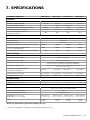
7. SPÉCIFICATIONS
PARAMÈTRE ONDULEUR
SAM-1000-12
SAM-1500-12
SAM-2000-12
SAM-3000-12
ENTRÉE
Tension de Système de Batterie
Tension d'Entrée Nominale
12 VCC
12 VCC
12 VCC
12 VCC
12,5 VCC
12,5 VCC
12,5 VCC
12,5 VCC
Plage de Tension d'Entrée
Courant d'Entrée à Puissance Continue
> 10,5 VCC á < 15,0 (± 0.5) VCC
100A
150A
200A
300A
Courant d'Entrée sans Charge
0,5A á 0,6A
0,65A á 0,75A
0,75A á 0,85A
0,85A á 0,95A
Efficacité maximale (à 50% de
Puissance continue)
90%
90%
90%
90%
SORTIE
Forme d'Onde de Sortie
Onde SinusoÏdale Modifiée
Tension de Sortie
115 VCA
FRÉQUENCE DE SORTIE
60 Hz ± 5%
Puissance de Sortie, Continue (Charge Résistive)
1000W
1500W
2000W
3000W
Puissance de Sortie, Surpuissance
(<1 Sec., Charge Résistive)
2000W
3000W
4000W
6000W
90%
90%
90%
Rendement Max. (à 50% de Puissance Continue)
90%
Protections
Alarme de Sous-tension
Oui. 10,8 VCC ± 0,3 VCC
Fermeture de Sous-tension
10,5 VCC ± 0,3 VCC
Fermeture de Surtension
Oui.15,5 VCC ± 0,2 VCC
Oui. (Fermetures en état d'arrêt. Réarmement manuel par
Mise hors tension et activation de l'interrupteur ON / OFF)
Fermeture de Surcharge et de Fuite à la Terre
Hot spot interne de 88°C - 115°C. Auto-réinitialisée lorsque
se refroidit de 10°C à 15°C
Fermeture de Surchauffe
La charge de refroidissement du
ventilateur contrôlé, à:
28 á 32W
GROUND FAULT PROTECTION
Yes. Shutdown.
Fusible d'Entrée CC: 32V
120A (4 x 30A)
90 á 110W
90 á 110W
Yes. Shutdown.
Yes. Shutdown.
240A (8 x 30A)
90 á 110W
Yes. Shutdown.
350A (10 x 35A)
480A (16 x 30A)
CONNEXIONS
Entrée CC connexions
Écrous et de boulons, M9
Sortie CA - No. de NEMA5-15R
2
2
3*
3*
GÉnÉral
0°C - 25°C / 32°F - 77°F á 100% loading;
26°C - 35°C / 78,8°F - 95°F á 80% loading
Plage de Température de Fonctionnement
Humidité de Fonctionnement
< 80%
LIASON DU NEUTRE AU CHÂSSIS
No. Neutre est flottant.
Dimensions (L x L x H) MM
Dimensions (L x L x H) POUCES
180 x 250 x 59
7,1 x 9,84 x 2,32
POIDS
1,69 kg.
3,72 lbs.
202 x 283 x 84
202x 345 x 84
7,95 x 11,14 x 3,3 7.95 x 13,58 x 3,3
3,2 kg.
7,1 lbs.
3,9 kg.
8,5 lbs.
202 x 420 x 84
7,95 x 16,53 x 3,3
5,5 kg.
11,8 lbs.
NOTE: Les spécifications pourraient changer sans avis
* Chacun des 3 NEMA5-15R récipients est protégé par disjoncteur 15A.
SAMLEX AMERICA INC. | 25
SECTION 8 | Warranty
2 Year limited warranty
SAM-1000-12, SAM-1500-12, SAM-2000-12 & SAM-3000-12 manufactured by Samlex America, Inc. (the “Warrantor“) is warranted to be free from defects in workmanship and materials under normal use and service. The warranty period is 2 years for the United States
and Canada, and is in effect from the date of purchase by the user (the “Purchaser“).
Warranty outside of the United States and Canada is limited to 6 months. For a warranty
claim, the Purchaser should contact the place of purchase to obtain a Return Authorization Number.
The defective part or unit should be returned at the Purchaser’s expense to the authorized
location. A written statement describing the nature of the defect, the date of purchase,
the place of purchase, and the Purchaser’s name, address and telephone number should
also be included.
If upon the Warrantor’s examination, the defect proves to be the result of defective
material or workmanship, the equipment will be repaired or replaced at the Warrantor’s
option without charge, and returned to the Purchaser at the Warrantor’s expense. (Contiguous US and Canada only)
No refund of the purchase price will be granted to the Purchaser, unless the Warrantor is
unable to remedy the defect after having a reasonable number of opportunities to do so.
Warranty service shall be performed only by the Warrantor. Any attempt to remedy the
defect by anyone other than the Warrantor shall render this warranty void. There shall
be no warranty for defects or damages caused by faulty installation or hook-up, abuse or
misuse of the equipment including exposure to excessive heat, salt or fresh water spray, or
water immersion.
No other express warranty is hereby given and there are no warranties which extend
beyond those described herein. This warranty is expressly in lieu of any other expressed
or implied warranties, including any implied warranty of merchantability, fitness for the
ordinary purposes for which such goods are used, or fitness for a particular purpose, or
any other obligations on the part of the Warrantor or its employees and representatives.
There shall be no responsibility or liability whatsoever on the part of the Warrantor or its
employees and representatives for injury to any persons, or damage to person or persons,
or damage to property, or loss of income or profit, or any other consequential or resulting damage which may be claimed to have been incurred through the use or sale of
the equipment, including any possible failure of malfunction of the equipment, or part
thereof. The Warrantor assumes no liability for incidental or consequential damages of
any kind.
Samlex America Inc. (the “Warrantor”)
www.samlexamerica.com
26 | SAMLEX AMERICA INC.
SECTION 8 | Warranty
GARANTIE LIMITEE SOUS 2 ANS
SAM-1000-12, SAM-1500-12, SAM-2000-12 et SAM-3000-12 fabriqués par Samlex America,
Inc. (le « Garant ») sont garantis être non défectueux dans la conception et dans les matériaux, moyennant une utilisation et un service normaux. La période de garantie est de
2 ans pour les Etats-Unis et le Canada, et prend effet le jour de l’achat par l’utilisateur («
l’Acheteur »).
La garantie hors des Etats Unis et du Canada est limitée à 6 mois. Pour une réclamation
concernant la garantie, l’Acheteur devra contacter le point de vente ou l’achat a été effectué afin d’obtenir un Numéro d’Autorisation pour le Retour.
La pièce ou l’unité défectueuse devra être retournée aux frais de l’acheteur au point
de vente agrée. Une déclaration écrite décrivant la nature du défaut, la date et le lieu
d’achat ainsi que le nom, l’adresse et le numéro de téléphone de l’Acheteur devront
également être renseignés.
Si a l’examination de la demande par le Garant, le défaut est réellement le résultat d’un
matériau ou d’un assemblage défectueux, l’équipement sera réparé ou remplacé gratuitement et renvoyé a l’Acheteur aux frais du
Garant. (Etats-Unis et Canada uniquement).
Aucun remboursement du prix d’achat ne sera accorde a l’Acheteur, sauf si le Garant est
incapable de remédier au défaut après avoir eu plusieurs occasion de le faire. Le service
de garantie doit être effectue uniquement par le Garant. Toute tentatives de remédier au
défaut par quelqu’un d’autre que le Garant rendent cette garantie nulle et sans effet. Il
n’existe aucune garantie concernant les défauts ou dommages causés par une installation
défectueuse ou inadaptée, par un abus ou une mauvaise utilisation de l’équipement, y
compris, une exposition excessive a la chaleur, au sel, aux éclaboussures d’eau fraiche ou a
l’immersion dans l’eau.
Aucune autre garantie express n’est accordée et il n’existe aucunes garanties qui
s’étendent au delà des conditions décrites par la présente. Cette garantie est la seule
garantie valable et reconnue par le Garant, et prédomine sur d’autres garantie implicites,
y compris les garanties implicites liées a la garantie de qualité marchande, a l’usage des
objectifs habituels pour lesquels de telles marchandises sont utilisées, ou l’usage pour un
objectif particulier, ou toutes autres obligations de la part du Garant ou de ses employés
et représentants.
Il ne doit pas exister de responsabilité ou autre de la part du Grant ou des ses employés et
représentants, en ce qui concerne les blessures corporelles, ou les dommages de personne
a personne, ou les dégâts sur une propriété, ou la perte de revenus ou de bénéfices, ou
autres dommages collatéraux, pouvant être rapportés comme ayant survenus au cours de
l’utilisation ou de la vente du matériel, y compris tous disfonctionnements ou échecs du
matériel, ou une partie de celui-ci. Le Garant n’assume aucune responsabilité concernant
toutes sortes de dommages accidentels ou indirects.
Samlex America Inc. (le « Garant »)
www.samlexamerica.com
SAMLEX AMERICA INC. | 27
Notes
28 | SAMLEX AMERICA INC.
Notes
SAMLEX AMERICA INC. | 29
Contact
Information
Toll Free Numbers
Ph: 800 561 5885
Fax: 888 814 5210
Local Numbers
Ph: 604 525 3836
Fax: 604 525 5221
Website
www.samlexamerica.com
USA Shipping Warehouse
Kent WA
Canadian Shipping Warehouse
Delta BC
Email purchase orders to
[email protected]
11002-SAM-1000-1500-2000-3000-0814