1
Intuition XG
Advanced HD/SD graphics co-processor
Installation & Quick Start Guide
M848-9005-470
w w w . m i r a n d a . c o m
Intuition XG-e
Intuition XG-3U-e
Intuition XG-Dual-e
Vertigo Suite v4.7
Advanced HD/SD Graphics Processors
Installation & Quick Start Guide
Copyright Notice
© 2011 Miranda Technologies Inc. All rights reserved.
Third Party Trademarks
All other brand names, product names or trademarks belong to their respective holders.
Usage Agreement
Please read the following terms and conditions carefully. By using the Intuition XG
Installation & Quick Start Guide, you agree to the following terms and conditions:
Miranda Technologies Inc. hereby grants permission and license to owners of Intuition XG
and Vertigo Suite to use their product manuals for their own internal business use. Manuals
for Miranda Technologies Inc. products may not be reproduced or transmitted in any form
or by any means, electronic or mechanical, including photocopying and recording, for any
purpose unless specifically authorized in writing by Miranda Technologies Inc.
Miranda Technologies Inc. makes no warranty, either expressed or implied, including but
not limited to any implied warranties of merchantability or fitness for a particular purpose,
regarding these materials and makes such materials available solely on an “As-Is” basis.
In no event shall Miranda Technologies Inc. be liable to anyone for special, collateral,
incidental, or consequential damages in connection with or arising out of purchase or use
of these materials. The sole and exclusive liability to Miranda Technologies Inc., regardless
of the form of action, shall not exceed the purchase price of the materials described herein.
Miranda Technologies Inc. reserves the right to revise and improve its products at any time
and without notice. This publication describes the state of this product at the time of its
publication, and may not reflect the product at all times in the future. Thus, different versions
of a manual may exist for any given product. Care should be taken to ensure that one
obtains the proper manual version for a specific product serial number.
Information in this document is subject to change without notice and does not represent a
commitment on the part of Miranda Technologies Inc.
Government Use
The Software {and Documentation} is provided with RESTRICTED RIGHTS. Use,
duplication or disclosure by the United States Government or any agency, department or
instrumentality thereof is subject to the restrictions set forth in the Commercial Computer
Software -- Restricted Rights clause at FAR 52.227-19 or the Commercial Computer
Software -- Licensing clause at NASA FAR Supplement 1852.227-86.
Printed in Canada
Document Identification
•
Title: Intuition XG - Installation & Quick Start Guide
•
Part number: M848-9005-470
•
Software version: Vertigo Suite v.4.7
•
Last revised: October 5, 2011
Safety Compliance
This equipment complies with the requirements of the following standards for
Safety of Information Technology Equipment:
• CSA C22.2 no. 60950-1-07 (2nd Edition)
• UL 60950-1 (2nd Edition)
• IEC/EN 60950-1 (2nd Edition)
Warning:
An appropriately listed/certified main supply power cord must be used for the
connection of the equipment to the main voltage at either 120V~ or 240V~
CAUTION:
These servicing instructions are for use by qualified service personnel only.
To reduce the risk of electric shock, do not perform any servicing than that
contained in the operating instructions unless you are qualified to do so. Refer all
servicing to qualified service personnel. Servicing should be done in a static-free
environment.
Electromagnetic Compatibility
This equipment has been tested for verification of compliance with FCC Part 15,
Subpart B requirements for Class A digital devices.
NOTE
This equipment has been tested and found to comply with the limits for a Class
A digital device, pursuant to Part 15 of the FCC rules. These limits are designed
to provide reasonable protection against harmful interference when the
equipment is operated in a commercial environment. This equipment
generates, uses and radiates radio frequency energy, and, if not installed and
used in accordance with the instruction manual, may cause harmful
interference in which case the user will be required to correct the interference
at his own expense.
This equipment has been tested and complies with the requirements of the
directive 2004/108/CE :
•
•
•
•
•
•
•
•
•
•
•
EN 55022 Class A Radiated emissions
EN 55022 Class A Conducted emissions
EN 61000 -3-2 Harmonic current emission limits
EN 61000 -3-3 Volatge fluctation and flicker limitations
EN 61000 -4-2 Electrostatic discharge immunity
EN 61000 -4-3 Radiated EMF immunity-RF
EN 61000 -4-4 Electrical fast transient immunity
EN 61000 -4-5 Surge immunity
EN 61000 -4-8 Power frequency magnetic field
EN 61000 -4-11 Voltage dips, short interruption and voltage variation immunity
ENV 50204 Radiated EMF immunity - 900MHz pulsed
WARNING
Vertigo XG devices contain Class 1 lasers, which are deemed safe under normal
operating conditions.
Standalone Equipment - Laser source(s) employed:
CLASS 1 LASER PRODUCT
APPAREIL A LASER DE CLASSE 1
TABLE OF CONTENTS
Introduction .......................................................................................................................... 1-1
Intuition XG product description ........................................................................................................ 1-2
Overview of the Intuition XG-e chassis.............................................................................................. 1-6
Front panel components (Intuition XG-e)...................................................................................... 1-7
Rear panel components (Intuition XG-e) ...................................................................................... 1-7
Overview of the Intuition XG-3U/Dual chassis................................................................................... 1-8
Front panel components (Intuition XG-3U/Dual)........................................................................... 1-9
Rear panel components (Intuition XG-3U/Dual) ......................................................................... 1-10
Installation instructions for the Intuition XG-e.................................................................. 2-1
Unpacking and verifying the Intuition XG-e shipped items ................................................................ 2-2
Mounting the Intuition XG-e chassis in a rack ................................................................................... 2-5
Cabling the Intuition XG-e unit........................................................................................................... 2-8
Installation instructions for the Intuition XG-3U/Dual ...................................................... 3-1
Unpacking and verifying the Intuition XG-3U/Dual’s shipped items................................................... 3-2
Mounting the Intuition XG-3U/Dual chassis in a rack ........................................................................ 3-6
Cabling the Intuition XG-3U/Dual unit.............................................................................................. 3-10
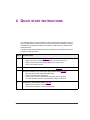
Quick start instructions....................................................................................................... 4-1
Starting the Intuition XG .................................................................................................................... 4-2
Assigning a new IP address to the Intuition XG device ..................................................................... 4-4
Verifying the installation and setup by previewing the playout .......................................................... 4-5
Completing the quick start procedure ................................................................................................ 4-8
Need further assistance? .................................................................................................... 5-1
Intuition XG Installation & Quick Start Guide
TOC-1
Table of Contents
TOC-2
Intuition XG Installation & Quick Start Guide
1 INTRODUCTION
This guide provides basic Intuition XG product information and an orientation of the
hardware components for all three (3) models of the Intuition XG (XG-e, XG-3U-e and XGDual-e). This guides also provides instructions for performing a first-time installation of the
Intuition XG devices, as well as initial setup tasks to get the devices up and running.
New Intuition XG devices are factory configured for standard rendering and playout
workflows. Configuring the Intuition XG settings for advanced workflows is normally
performed by qualified network administrators or Miranda’s Integration Specialists using the
Intuition XG Portal and Dashboard software interfaces. Information and instructions for
implementing advanced configurations is beyond the scope of this document, but are
covered in the “Intuition XG Configuration Guide”.
Intuition XG Installation & Quick Start Guide
1-1
Introduction
Intuition XG product description
The Intuition XG graphics co-processor significantly extends the graphics and clip playout
capabilities of master control switcher systems, like the Imagestore 750 or NV51000MC, by
feeding the HD/SD fill/key inputs. It’s ideal for playout of the most advanced data-driven,
channel branding and promotional graphics, including: “Coming up next” and episodic
promos. The Intuition XG provides multi-level character generation plus animation/still and
clip playout with multi-channel audio.
The Intuition XG is available in three (3) standard models:
Intuition-XG-e
A single channel graphics co-processor, generally used
upstream of a master control switcher like the Imagestore 750
or NV5100MC.
Fill
Video In A
•
•
•
•
•
•
•
•
•
Key
Out A
1RU chassis with a single power supply unit.
1 HD/SD video input, 1 HD/SD (Fill & Key) output
A powerful, HD/SD character generator which allows the
playout of virtually unlimited layers of animated text and
dynamically updated text.
1 TB RAID1 storage for up to 200 hours of video/audio
clips and simultaneous playout of multiple clips
Playout of up to eight (8) layers of animated and still
graphics templates for the most advanced branding and
promotional effects.
SD output as NTSC or PAL
HD output as 1080i, 720p or 480p
VANC + VBI extraction processing and insertion or
VAnc/VBI pass through.
Full automation control by serial, Ethernet and/or GPI
commands.
Options
•
VX-ClipPlayer
•
VX-Audio-e
1-2
Intuition XG Installation & Quick Start Guide
Introduction
Intuition-XG-3U-e
A single channel graphics co-processor, generally used
upstream of a master control switcher like the Imagestore 750
or NV5100MC.
Video In A
•
•
•
•
•
•
•
•
•
•
•
Fill
Key
Out A
3RU chassis with redundant power supply unit.
1 HD/SD video input, 1 HD/SD (Fill & Key) output
A powerful, HD/SD character generator which allows the
playout of virtually unlimited layers of animated text and
dynamically updated text.
1 TB RAID1 storage for up to 400 hours of video/audio
clips and simultaneous playout of multiple clips
Playout of up to eight (8) layers of animated and still
graphics templates for the most advanced branding and
promotional effects.
SD output as NTSC or PAL
HD output as 1080i, 720p or 480p
VANC + VBI extraction processing and insertion or
VAnc/VBI pass through.
16 embedded audio channels
Discrete AES audio channels - up to 8 in and 16 out
Full automation control by serial, Ethernet and/or GPI
commands.
Options
•
VX-ClipPlayer
•
VX-Audio-e
•
VX-EAS
•
VX-GPI-8-eVX-RS422-2-e
•
VX-TC-e
•
VX-2TB-UPG
Intuition XG Installation & Quick Start Guide
1-3
Introduction
Intuition-XG-Dual-e
A dual channel graphics co-processor, generally used
upstream of a master control switcher like the Imagestore 750
or NV5100MC.
Fill
Key
Video In A
Video In B
•
•
•
•
•
•
•
•
•
•
•
Out A
Fill
Key
Out B
3RU chassis with redundant power supply unit.
2 HD/SD video input, 2 HD/SD (Fill & Key) output
A powerful, HD/SD character generator which allows the
playout of virtually unlimited layers of animated text and
dynamically updated text.
1 TB RAID1 storage for up to 400 hours of video/audio
clips and simultaneous playout of multiple clips
Playout of up to eight (8) layers of animated and still
graphics templates for the most advanced branding and
promotional effects.
SD output as NTSC or PAL
HD output as 1080i, 720p or 480p
VANC + VBI extraction processing and insertion or
VAnc/VBI pass through.
16 embedded audio channels per SDI stream
Discrete AES audio channels - up to 8 in and 2 x 16 out
Full automation control by serial, Ethernet and/or GPI
commands.
Options
•
VX-ClipPlayer
•
VX-Audio-e
•
VX-EAS
•
VX-GPI-8-eVX-RS422-2-e
•
VX-TC-e
•
VX-2TB-UPG
1-4
Intuition XG Installation & Quick Start Guide
Introduction
The following options are available on Intuition XG devices:
VX-ClipPlayer
Clip Player
The Clip Player is an internal codec package for playing out multi-format
video clips.
VX-Audio-e
Audio Processing
The discrete audio I/O card allows the Intuition XG to capture, process and
output discrete audio. The number of discrete audio I/O channels depends
on the model of Intuition XG:
•
Intuition-XG-e => None
•
Intuition-XG-3Ue and Intuition-XG-Dual-e => 8 in / 16 out
VX-GPI-8-e
GPI card
The GPI card allows for control of the Intuition XG via GPI triggers. The
card allows for up to 8 GPI in and 8 GPI out.
VX-EAS
EAS Text Integration (EAS Plugin and EAS Software Panel)
High quality EAS text and audio can be played out with the Intuition XG
processor, using templates which integrate channel branding graphics for
a consistent on-air presentation.
Only available for the Intuition-XG-3U-e and Intuition-Dual-e models.
VX-RS422-2-e
2 port RS-422 card
The RS-422 card provides an interface upon which the Intuition XG can
communicate with automation systems.
Only available for the Intuition-XG-3U-e and Intuition-Dual-e models.
VX-TC-e
Time Code card
The Time Code card allows you to lock the Intuition XG’s system clock to
an external timecode.
Only available for the Intuition-XG-3U-e and Intuition-Dual-e models.
VX-2TB-UPG
1 TB RAID-10 Expansion option (2 x 1TB)
Increases the usable storage from 1TB to 2TB.
Only available for the Intuition-XG-3U-e and Intuition-Dual-e models.
Intuition XG Installation & Quick Start Guide
1-5
Introduction
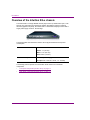
Overview of the Intuition XG-e chassis
The Intuition XG-e is a single HD/SD channel playout server (1 HD/SD video input, 1 HDSDI Fill + Key output) that incorporates the Intuition XG graphics engine to rendering
advanced graphics. Physically, the Intuition XG is a 1RU rackmount playout server with a
single power supply unit and 1 TB of storage.
The following table summarizes the Intuition XG-e’s physical dimensions and power
consumption:
Chassis
FORM: 1U rackmount chassis
HEIGHT: 1.7” (43 mm)
WIDTH: 17.2” (437 mm)
DEPTH: 28.2” (716 mm)
Power consumption
1 x 1400W power supply
AC input: 180 - 240V, 50 - 60 Hz, 7.2 - 9.5 Amp
The following sections provide more information about Intuition XG-e hardware
components:
1-6
•
“Front panel components (Intuition XG-e)” on page 1-7
•
“Rear panel components (Intuition XG-e)” on page 1-7
Intuition XG Installation & Quick Start Guide
Introduction
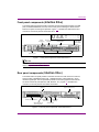
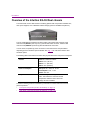
Front panel components (Intuition XG-e)
The Intuition XG’s front panel provides convenient access to the SATA hard drives, two USB
ports, a CD/DVD ROM drive, two fans, and a control panel containing five LEDs and two
buttons for system monitoring and operation. Figure 1-1 identifies the LEDs, buttons and
connectors on the front panel of the Intuition XG-e.
2
Universal
Info. LED
USB 2.0
Connectors (2)
RS-232 Serial Port
(Disabled)
Power Supply Unit
NIC 2 LED
1
NIC 1 LED
HDD LED
Power LED
Reset
button
CD/DVD ROM Drive
Power On/Off
button
Control Panel
LEDs & Buttons
SATA Hard Drives
Figure 1-1. Front panel components of the Intuition XG-e
NOTE
See the “Intuition XG Configuration Guide” for descriptions of each of the LEDs and buttons
on the front panel of the Intuition XG-e.
Rear panel components (Intuition XG-e)
The Intuition XG’s rear panel provides convenient access to the video card’s I/O connector,
which provides 1 SD/HD SDI video input, 1 SD/HD SDI video output (Fill & Key), and a
reference signal input. The rear panel also provides access to the graphics card connector,
as well as various I/O ports (RS-232, USB, Ethernet...etc.). Figure 1-4 identifies each
connector on the rear panel of the Intuition XG chassis.
IPMI Connector
(Not used)
SDI Video Card I/O Connector
Graphics Card Connectors (2)
(Only one connector used)
Network Ethernet
Connectors (2)
USB 2.0 Connectors (2)
(Mouse & Keyboard)
VGA Connector
(Disabled)
A/C Power Input
Serial RS-232 Port
Figure 1-2. The rear panel components of the Intuition XG-e
Intuition XG Installation & Quick Start Guide
1-7
Introduction
Overview of the Intuition XG-3U/Dual chassis
The Intuition XG unit is a 3RU rackmount rendering platform that incorporates redundant fans,
three power supplies, and 1 TB RAID1-enabled storage (optional 2 TB RAID10 expansion).
The only visible difference between the 3RU models of the Intuition XG is that the single
channel model (XG-3U-e) has only one (1) discrete AES audio connector, while the dual
channel model (XG-Dual-e) has two (2) discrete AES audio connectors.
In some cases, the positioning of the connectors on the Intuition XG’s rear panel differs
depending upon the hardware options installed. See page 1-6 for a list of the Intuition XG’s
hardware options.
The following table summarizes the Intuition XG’s physical dimensions and power consumption:
Chassis
FORM: 3U rackmount chassis
HEIGHT: 5.2” (132 mm)
WIDTH: 17.7” (450 mm)
DEPTH: 25.5” (648 mm)
Power consumption
AC input: 100 - 240V, 50 - 60 Hz
Consumption: 4.05 - 1.73A
Power: 410 max.
Temperature
Ambient temperature: 35 ° C
Note: This shall be the maximum internal
temperature within the rack in which the
Vertigo XG unit is installed.
Consult the following sections to familiarize yourself with the Intuition XG’s front and rear
panel components:
1-8
•
“Front panel components (Intuition XG-3U/Dual)” on page 1-9
•
“Rear panel components (Intuition XG-3U/Dual)” on page 1-10
Intuition XG Installation & Quick Start Guide
Introduction
Front panel components (Intuition XG-3U/Dual)
The Intuition XG’s front panel provides convenient access to the hard drives, two USB ports,
a CD/DVD ROM drive, and a control panel containing six LEDs and three buttons for system
monitoring and operation. Figure 1-3 identifies each component on the Intuition XG’s front
panel.
SYSTEM ALERT
/ POWER FAILURE
LAN 2
OVERHEAT
/ FAN FAIL
HDD
ACTIVITY
LAN 1
POWER
INDICATOR
POWER
CD/DVD
ROM DRIVE
HARD DRIVES
FLOPPY
DRIVE
USB 2.0
CONNECTORS (2)
Figure 1-3. The Intuition XG’s front panel components
NOTE
See the “Intuition XG Configuration Guide” for descriptions of each of the LEDs and buttons
on the Intuition XG’s front panel.
Intuition XG Installation & Quick Start Guide
1-9
Introduction
Rear panel components (Intuition XG-3U/Dual)
The Intuition XG’s rear panel provides convenient access to the video card’s I/O connector,
which provides 4 SD/HD SDI video outputs, a reference signal input, and AES audio
input/output. The rear panel also provides access to the graphics card connector, as well
as various I/O ports (RS-422, USB, Ethernet...etc.).
Figure 1-4 identifies the components and connectors on the rear panel of the Intuition XG
chassis.
System Fans (2)
Power Supply Modules (3)
LTC
IN
LTC
IN
Graphics Card
Connectors (2)
Keyboard
Connector
Mouse
Connector
GPI Card Connector
(option)
Network Ethernet
Connectors (2)
Serial
RS-232 Ports (2)
USB 2.0
Connectors (4)
Audio I/O Ports
(Disabled)
RS-422 Connectors
(option)
Time Code
Card
Discrete Audio
Connectors (2)
(option)
SDI Video Card
I/O Connector
Figure 1-4. The Intuition XG’s rear panel components (XG-3U-e & XG-Dual-e models)
NOTE
In some cases, the positioning of the connectors on the Intuition XG’s rear panel differs
depending upon the hardware options installed. See page 1-6 for a list of the Intuition XG’s
hardware options.
1-10
Intuition XG Installation & Quick Start Guide
2 INSTALLATION INSTRUCTIONS FOR THE
INTUITION XG-E
This chapter identifies and describes the tasks for performing a first-time installation of a
factory-configured Intuition XG-e device.
CA UTION
Intuition XG devices should only be installed by trained personnel in a restricted access
locations only. All health and safety regulations and precautions must be observed.
Step #
Task description
1
Unpack the parts included in the shipping package (page 2-2)
•
Verify the completeness and condition of all of the items included in the shipping package
•
Familiarize yourself with each of the items related to the Intuition XG-e
2
Install the Intuition XG-e chassis in a rack (page 2-5)
•
Remove the faceplate from the Intuition XG-e unit
•
Install the rails on the side of the Intuition XG-e unit and in the rack slot
•
Mount the Intuition XG-e unit in the rack and re-attach the faceplate
3
Cabling the Intuition XG-e unit (page 2-8)
•
Connect the SDI video I/O cable
•
Connect the keyboard and mouse
•
Connect the ethernet network cables
•
Connect the DVI monitor
•
Connect the automation system cable to the RS-232
•
Connect the power supply cable
Intuition XG Installation & Quick Start Guide
2-1
Installation instructions for the Intuition XG-e
Unpacking and verifying the Intuition XG-e shipped
items
The Intuition XG-e device is packaged and shipped with the items listed in the table below. As
you unpack the contents of the shipment, please verify the completeness and condition of the
contents of the shipment. We also recommend that before attempting to install the unit, you use
the table below to familiarize yourself with each of the items related to the Intuition XG-e.
NOTE
If any damage occurred during transportation or if any items are missing from the package,
please contact Miranda’s Customer Service and Sales department.
1 x 1RU Intuition XG-e chassis
The Intuition XG-e single channel graphics engine provides
1 input and 1 output (fill & key).
Rack mounting kit
•
2 x chassis rail assemblies (inner & outer rails)
•
Rail screws & washer kit
AC power cable
One power cable is provided, which connects to the single
1400W power supply on the rear of the Intuition XG-e chassis.
Video breakout cable
The breakout cable is used to connect the Video Card I/O
connector to the SDI input, reference input, reference output,
and SDI outputs. See page 2-8 for cabling instructions.
Keyboard and Mouse
A keyboard and mouse are required during the Intuition XG’s
initial setup, which involves using the Intuition XG’s desktop
applications, including Dashboard.
Both the keyboard and mouse provided can be connected to the
USB 2.0 connectors on the front or rear panels of the
Intuition XG-e device.
2-2
Intuition XG Installation & Quick Start Guide
Installation instructions for the Intuition XG-e
VGA/DVI monitor adapter
A computer monitor is required during the Intuition XG’s initial
setup, which involves using the Intuition XG’s desktop
applications, including Dashboard.
The Intuition XG’s graphics card connectors allow you to
connect to a DVI monitor. If you prefer, you can use the VGA/DVI
adapter to connect the Intuition XG device to VGA monitor.
Note that although there are two (2) DVI connectors, the
Intuition XG can display to only one monitor. Therefore, it does
not matter which of the two connectors the monitor’s cable is
connected to.
System Recovery DVD package
2 x System Recovery DVDs
These DVDs can be used to restore the Intuition XG unit to its
original factory default configuration. Note that one of the DVDs
has a sticker with the Intuition XG’s serial number, which
identifies that particular Intuition XG unit.
Store these the System Recovery DVDs in a safe location.
Do not misplace.
Vertigo Suite DVD package
•
The Demo content DVD contains various sample content,
system templates, and EAS templates, which can be
imported into the Intuition XG’s database.
•
The Software & User Documentation DVD contains a
complete installation of the Vertigo Suite software and the
user documentation. A sticker on the DVD identifies the
release version of the Vertigo Suite software.
Please consult http://support.miranda.com for the latest
software and documentation updates.
Intuition XG Configuration Guide
A printed copy of the Intuition XG Configuration Guide, which
provides practical reference and procedural information on how
to use the Intuition XG’s desktop and remote configuration
applications to configure the Intuition XG graphics processing
system.
Please consult http://support.miranda.com for the latest
documentation updates.
Intuition XG Installation & Quick Start Guide
2-3
Installation instructions for the Intuition XG-e
•
Miranda Technical Support Contacts and Warranty card
•
This card contains warranty information related to the
Intuition XG hardware and software. It also identifies
Miranda’s contact information, which is also provided on
page 5-1.
License Agreement card (Miranda Technologies Inc.)
This card describes the terms of Miranda’s license
agreement for the Intuition XG and Vertigo Suite software.
ATI FirePro kit
The ATI FirePro kit items are not required during the installation
of a factory configured Intuition XG.
The Intuition XG uses the ATI FirePro graphics card. As such,
the following ATI FirePro’s installation items are also included in
the Intuition XG shipping package:
•
Quick Installation Guide
•
Installation Driver CD
•
Multi-display Configurations with Eyefinity sheet
•
ATI CrossFire Pro flex connector
SuperMicro User’s Manual and Bootable CD
These SuperMicro items are not required during the installation
of a factory configured Intuition XG.
The Intuition XG uses SuperMicro’s motherboard. As such, the
documentation and bootable CD (drivers & utilities) have been
included in the Intuition XG shipping package.
Windows Embedded Runtime Product Key
This flyer provides information regarding the Microsoft Runtime
Key that applies to the Windows Embedded Standard software
that is installed on the Intuition XG unit.
Store this flyer in a safe location as to not misplace it.
2-4
Intuition XG Installation & Quick Start Guide
Installation instructions for the Intuition XG-e
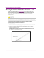
Mounting the Intuition XG-e chassis in a rack
Included in the shipping package is a Rack mounting kit, which contains the rails, screws
and washers required to mount the Intuition XG-e (1RU) chassis into an equipment rack.
Note that the rails are designed to fit in racks with a depth of 28” to 33”.
The two quick-release rail assemblies each consists of two primary sections: an inner fixed
chassis rail and inner rail extension that secure directly to the chassis, and an outer rail
assembly that secures directly to the rack itself.
CA UTION
Intuition XG devices are intended to be installed in a restricted access location by qualified
personnel. All health and safety regulations and precautions must be observed.
The following procedure provide step-by-step instructions for installing the rails and
mounting the Intuition XG-e chassis into an equipment rack.
To install the Intuition XG-e chassis:
1. Remove the Intuition XG faceplate by pulling the faceplate’s handles away from the chassis.
2. Place the inner rail extensions over the pre-attached inner rails which are attached to
the side of the chassis. Align the hooks of the inner rail with the rail extension holes.
Make sure the extension faces "outward" just like the inner rail.
3. Slide the extension toward the front of the chassis.
4. Secure the chassis with screws.
Intuition XG Installation & Quick Start Guide
2-5
Installation instructions for the Intuition XG-e
2-6
5.
Repeat steps 2 to 4 for the other inner rail extension.
6.
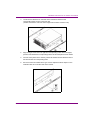
Each outer rail is in two sections that must be assembled before mounting onto the rack.
a. Identify the left and right outer rails by examining the ends which bend outward.
b. Slide the front section of the outer rail into the rear section of the outer rail.
7.
Install the outer rails onto the rack.
a. Adjust the outer rails to the proper length so that the outer rail fits snugly within the rack.
b. Align the holes on the front of the outer rail, with the holes on the front of the rack
and secure with the screws provided.
c. Align the holes on the rear of the outer rail to the holes on the rack and secure with
the screws provided.
d. Repeat the procedure with the second outer rail assembly.
Intuition XG Installation & Quick Start Guide
Installation instructions for the Intuition XG-e
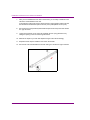
CA UTION
Due to the heavy weight of the Intuition XG device, ensure that the rack is securely anchored
onto a unmovable surface or structure before installing the chassis into the rack.
8.
Install the chassis into a rack.
a. Confirm that chassis includes the inner rails and rail extensions. Also, confirm that
the outer rails are installed on the rack.
b. Line chassis rails with the front of the rack rails.
c. Slide the chassis rails into the rack rails, keeping the pressure even on both sides
(you may have to depress the locking tabs when inserting). When the server has
been pushed completely into the rack, you should hear the locking tabs "click".
d. (Optional) Insert and tightening the thumbscrews that hold the front of the server
to the rack.
Intuition XG Installation & Quick Start Guide
2-7
Installation instructions for the Intuition XG-e
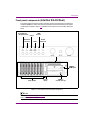
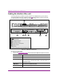
Cabling the Intuition XG-e unit
Once the Intuition XG-e chassis is securely mounted in an equipment rack, you can connect
the required cables to the rear connectors. Figure 2-1 and the cabling procedure provide stepby-step instructions for properly cabling the Intuition XG-e unit.
2
1
2
3
4
5
6
Legend
1 SDI Video I/O connector
2 Mouse & keyboard connectors
3 Ethernet Network connectors
4 Automation system connection (RS-232)
5 DVI Monitor connectors
6 Power supply
*The numbers correspond to the steps in the cabling procedure
Figure 2-1. Cabling the Intuition XG-e
To cable the Intuition XG-e:
1. Connect the Video breakout cable to the Intuition XG’s SDI Video card I/O connector.
2-8
SDI IN A
Primary SDI program input connection for the Intuition XG-e unit.
SDI IN B
Not used on an Intuition XG-e unit.
SDI OUT A (FILL 1)
Primary output channel connection for the Intuition XG-e unit.
For the purposes of this setup procedure, connect this cable to a
broadcast monitor.
SDI OUT B
Not used on an Intuition XG-e unit.
SDI OUT C / KEY
The matching key signal for SDI OUT A.
Intuition XG Installation & Quick Start Guide
Installation instructions for the Intuition XG-e
SDI OUT D /KEY
Not used on an Intuition XG-e unit.
ANALOG REF IN
Connect to a house reference (Analog Blackburst or HD Tri-Level)
to synchronize the phase timing video and graphics processing.
ANALOG REF
LOOP OUT
Optional connection. Use to feed the reference signal from
ANALOG REF IN to another piece of equipment.
2.
Connect the Keyboard and Mouse to the USB connectors on the front or rear
panel of the Intuition XG-e.
3.
Connect the Intuition XG device to the Local Area Network (LAN) by connecting
ethernet cables to the two (2) Network Ethernet connectors.
The Intuition XG’s two network ethernet adapters are teamed together (connect 2 cables to
the 2 NIC cards at the same time) to form a third virtual adapter. In the event of an adapter,
cable or switch failure, the network interface fails over to the healthy adapter. See “Intuition
XG Configuration Guide” for more details.
If you only have one cable connected, then the teaming is still in effect, but all traffic will be
over that one cable. If that NIC fail, you will have to manually move the cable to the other NIC.
4.
Connect the automation system cables to the Intuition XG’s RS-232 connector.
The RS-232 connector provides a control port upon which the automation system’s
serial cable can be connected. It is through this connection that the automation system
communicates and controls the Intuition XG using automation protocol commands.
5.
Connect a computer monitor to one of the two (2) DVI connectors on the rear
panel of the Intuition XG. If you prefer, you can use the VGA/DVI monitor adapter to
connect the Intuition XG device to VGA monitor.
NOTE
Although there are two (2) DVI connectors, the Intuition XG can display to only one monitor.
Therefore, it does matter which of the two connectors the monitor’s cable is connected to.
6.
Connect the AC power cable to the power supply socket on the rear panel of the
Intuition XG-e chassis.
WA RNING
DO NOT plug the power cable into AC power socket yet.
Intuition XG Installation & Quick Start Guide
2-9
Installation instructions for the Intuition XG-e
2-10
Intuition XG Installation & Quick Start Guide
3 INSTALLATION INSTRUCTIONS FOR THE
INTUITION XG-3U/DUAL
This chapter provides you with instructions for performing a first-time installation of a
factory-configured Intuition XG-3U-e or Intuition XG-Dual-e devices.
CA UTION
Intuition XG devices should only be installed by trained personnel in a restricted access
locations only. All health and safety regulations and precautions must be observed.
Step #
Task description
1
Unpack the parts included in the shipping package (page 3-2)
•
Verify the completeness and condition of all of the items included in the shipping package
•
Familiarize yourself with each of the items related to the Intuition XG
2
Install the Intuition XG chassis in a rack (page 3-6)
•
Remove the faceplate from the Intuition XG unit
•
Install the rails on the side of the Intuition XG unit and in the rack slot
•
Mount the Intuition XG unit in the rack and re-attach the faceplate
3
Cabling the Intuition XG unit (page 3-10)
•
Connect the power supply cables
•
Connect the keyboard and mouse
•
Connect the DVI monitor
•
Connect the ethernet network cable(s)
•
Connect the SDI video I/O cable
•
Connect the discrete AES audio cable(s)
•
Connect the automation system cable to the RS-232 / RS-422 ports
•
Connect cable to time code card
•
Connect cable to GPI card
Intuition XG Installation & Quick Start Guide
3-1
Installation instructions for the Intuition XG-3U/Dual
Unpacking and verifying the Intuition XG-3U/Dual’s
shipped items
The Intuition XG device is packaged and shipped with the items listed in the table below. As you
unpack the contents of the shipment, please verify the completeness and condition of the
contents of your received shipment. We also recommend that before attempting to install the unit,
you use the table below to familiarize yourself with each of the items related to the Intuition XG.
NOTE
If any damage occurred during transportation or if any items are missing from the package,
please contact Miranda’s Customer Service and Sales department.
1 x 3RU Intuition XG chassis
•
VX-Intuition-XG-3U-e
A single channel graphics engine, which provides 1 input and
1 output (fill & key).
•
VX-Intuition-XG-Dual-e
A dual channel graphics engine, which provides 2 input and
2 output (fill & key).
Rack mounting kit
•
2 x chassis rail assemblies (inner & outer rails)
•
Rail screws & washer kit
AC power cables
Three (3) power cables are provided, which connect to the
Intuition XG’s three 380W power supplies.
Video breakout cable
The breakout cable is used to connect the Video Card I/O
connector to the SDI inputs, reference input, reference output,
and SDI outputs. See page 3-11 for cabling instructions.
3-2
Intuition XG Installation & Quick Start Guide
Installation instructions for the Intuition XG-3U/Dual
Discrete (AES) audio breakout cable
Single channel Intuition XG units (XG-3U-e) have one discrete
(AES) audio connector, while dual channel Intuition XG units (XGDual-e) have two discrete (AES) audio connectors.
For each physical SDI video output, there will be a discrete audio
breakout cable. Each discrete audio breakout cable contains 4
BNC inputs and 8 BNC outputs. Each BNC connector represents
1 stereo pair (2 channels) of digital AES/EBU audio. Therefore,
each discrete audio breakout cable contains 4 stereo pairs
(8 channels) of input and 8 stereo pairs (16 channels) of output.
VGA/DVI monitor adapter
A computer monitor is required during the Intuition XG’s initial
setup, which involves using the Intuition XG’s desktop
applications, including Dashboard.
The Intuition XG’s graphics card connectors allow you to connect
to a DVI monitor. If you prefer, you can use the VGA/DVI adapter
to connect the Intuition XG device to VGA monitor.
Note that although there are two (2) DVI connectors, the Intuition
XG can display to only one monitor. Therefore, it does not matter
which of the two connectors the monitor’s cable is connected to.
Keyboard and Mouse
A keyboard and mouse are required during the Intuition XG’s
initial setup, which involves using the Intuition XG’s desktop
applications, including Dashboard.
Both the keyboard and mouse provided can be connected to the
USB 2.0 connectors on the front or rear panels of the Intuition XG
device.
If you prefer to use a mouse and/or keyboard that has a PS/2
connection, there are two (2) PS/2 connectors available on the
rear panel of the Intuition XG device.
Hard Disk Drive (HDD) screws
The HDD screws are not required during the initial installation of
a factory configured Intuition XG.
The HDD screws are required to perform an on-site installation of
the 1 TB RAID10 Expansion option (VX-2TB-UPG), which
increases the Intuition XG’s usable storage from 1TB to 2TB.
Therefore, we recommend storing the HDD screws for future use.
Intuition XG Installation & Quick Start Guide
3-3
Installation instructions for the Intuition XG-3U/Dual
System Recovery DVD package
2 x System Recovery DVDs
These DVDs can be used to restore the Intuition XG unit to its
original factory default configuration. Note that one of the DVDs
has a sticker with the Intuition XG’s serial number, which identifies
that particular Intuition XG unit.
Store these the System Recovery DVDs in a safe location.
Do not misplace.
Vertigo Suite DVD package
•
The Demo content DVD contains various sample content,
system templates, and EAS templates, which can be
imported into the Intuition XG’s database.
•
The Software & User Documentation DVD contains a
complete installation of the Vertigo Suite software and the
user documentation. A sticker on the DVD identifies the
release version of the Vertigo Suite software.
Please consult http://support.miranda.com for the latest
software and documentation updates.
Intuition XG Configuration Guide
A printed copy of the Intuition XG Configuration Guide, which
provides practical reference and procedural information on how to
use the Intuition XG’s desktop and remote configuration
applications to configure the Intuition XG graphics processing
system.
Please consult http://support.miranda.com for the latest
documentation updates.
•
Miranda Technical Support Contacts and Warranty card
•
This card contains warranty information related to the
Intuition XG hardware and software. It also identifies
Miranda’s contact information, which is also provided on
page 5-1.
License Agreement card (Miranda Technologies Inc.)
This card describes the terms of Miranda’s license
agreement for the Intuition XG and Vertigo Suite software.
3-4
Intuition XG Installation & Quick Start Guide
Installation instructions for the Intuition XG-3U/Dual
ATI FirePro kit
The ATI FirePro kit items are not required during the installation
of a factory configured Intuition XG.
The Intuition XG uses the ATI FirePro graphics card. As such, the
following ATI FirePro’s installation items are also included in the
Intuition XG shipping package:
•
Quick Installation Guide
•
Installation Driver CD
•
Multi-display Configurations with Eyefinity sheet
•
ATI CrossFire Pro flex connector
SuperMicro User’s Manual and Bootable CD
These SuperMicro items are not required during the installation
of a factory configured Intuition XG.
The Intuition XG uses SuperMicro’s motherboard. As such, the
documentation and bootable CD (drivers & utilities) have been
included in the Intuition XG shipping package.
Windows Embedded Runtime Product Key
This flyer provides information regarding the Microsoft Runtime
Key that applies to the Windows Embedded Standard software
that is installed on the Intuition XG unit.
Store this flyer in a safe location as to not misplace it.
Intuition XG Installation & Quick Start Guide
3-5
Installation instructions for the Intuition XG-3U/Dual
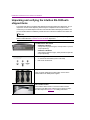
Mounting the Intuition XG-3U/Dual chassis in a rack
Included in the shipping package is a Rack mounting kit, which contains the rails, screws
and washers required to mount the Intuition XG chassis into an equipment rack. Note that
the rails are designed to fit in racks with a depth of 28” to 33”. Due to the heavy weigh of the
unit, the rack in which the Intuition XG unit will be installed should be anchored to the
building’s structure.
CA UTION
Intuition XG devices are intended to be installed in a restricted access location by
qualified personnel. All health and safety regulations and precautions must be observed.
The following instructions provide step-by-step instructions for installing the rails and
mounting the Intuition XG chassis into an equipment rack.
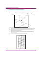
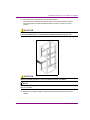
To install chassis rails:
1. Remove the Intuition XG faceplate by pulling the faceplate’s handles away from the chassis.
2.
Included in the shipping package are a pair of rail assemblies. In each rail assembly,
locate the inner rail and outer rail.
Press the locking tab to release the inner rail from its locking position and pull out the
inner rail from the rail assembly. (The inner rails are to be attached to the chassis and
the outer rails are to be installed in the rack).
Outer rail (to be installed in the rack)
Pull out the inner rail
(to be attached on the chassis)
Press the Locking tab
3-6
Intuition XG Installation & Quick Start Guide
Installation instructions for the Intuition XG-3U/Dual
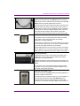
3.
Locate the five rail buttons on each side of the chassis and locate the five
corresponding holes on each of the inner rails.
(*Please note that one end of the hole is larger than the other end of the hole.)
4.
Align the larger end of each hole against its corresponding button. Once all aligned,
push the holes toward their corresponding buttons and the rail is placed on the chassis.
5.
Once the rail is placed on the chassis, pull the rail forward until the rail buttons lock in
the small ends of the corresponding holes.
6.
Secure the rail to the chassis with a Type G screw. Repeat the above steps 2 to 6 to
install the other rail on the other side of the chassis.
Intuition XG Installation & Quick Start Guide
3-7
Installation instructions for the Intuition XG-3U/Dual
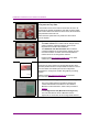
7.
After you have installed the inner rails on the chassis, you are ready to install the outer
rails of the rail assemblies to the rack.
In the package, locate a pair of front (-short) and rear (-long) brackets. Please note that
the brackets are marked with Up/Front arrows (-front) and Up/Rear arrows (-rear).
8.
Secure the front (-short) bracket (marked with the Up/Front arrows) to the outer rail with
two Type G screws.
9.
Locate the two buttons on the outer rail and attach the rear (-long) bracket to it by
sliding the opening of the rear rail through the button.
10. Measure the depth of your rack and adjust the length of the rails accordingly.
11. Repeat the same steps to install the outer rail on the chassis.
12. Secure both outer rail assemblies to the rack with Type H screws and Type I washers.
3-8
Intuition XG Installation & Quick Start Guide
Installation instructions for the Intuition XG-3U/Dual
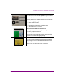
13. Slide the Intuition XG chassis into the rack as shown below.
The chassis may not slide into the rack smoothly or easily when installed for the first
time. Adjustments to the slide assemblies might be necessary to achieve a smooth
insertion.
CA UTION
Due to the heavy weight of the Intuition XG device, ensure that the rack is securely anchored
onto a unmovable surface or structure before installing the chassis into the rack.
CA UTION
Slide/rail mounted equipment is not to be used as a shelf or a workspace.
NOTE
To completely remove the chassis from the rack, you must release the safety tabs on both
sides of the chassis.
14. Re-attach the faceplate by aligning and pushing the faceplate towards the Intuition XG
chassis.
Intuition XG Installation & Quick Start Guide
3-9
Installation instructions for the Intuition XG-3U/Dual
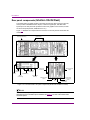
Cabling the Intuition XG-3U/Dual unit
Once the Intuition XG chassis is securely mounted in an equipment rack, you can connect
the required cables to the rear connectors of the Intuition XG unit. Figure 3-1 and the cabling
procedure provide step-by-step instructions for properly cabling the Intuition XG unit.
2
LTC
IN
1
2
7
4
3 7 8 5 6 9
Legend
1 Power supplies
2 Mouse & keyboard connectors
3 DVI Monitor connectors
4 Ethernet Network connectors
5 SDI Video I/O connector
6 Discrete (AES) Audio connector(s)
7 Option: Automation system connections (RS-232 or RS-422)
8 Option: Time Code Card connector
9 Option: GPI Card connector
*The numbers correspond to the steps in the cabling procedure
Figure 3-1. Cabling the Intuition XG
3-10
Intuition XG Installation & Quick Start Guide
Installation instructions for the Intuition XG-3U/Dual
To cable the Intuition XG-3U-e or the Intuition XG-Dual-e:
1. Connect the three (3) AC power cables to the power supply sockets on the rear
panel of the Intuition XG chassis.
WA RNING
DO NOT plug the power cables into AC power sockets yet.
2.
3.
Connect the Keyboard and Mouse to the USB connectors on the front or rear
panel of the Intuition XG. Two PS/2 connections are also available on the rear panel,
should you prefer to use another type of keyboard and mouse.
Connect to a monitor to one of the two (2) DVI connectors on the rear panel of
the Intuition XG. If you prefer, you can use the VGA/DVI monitor adapter to connect
the Intuition XG device to VGA monitor.
NOTE
Although there are two (2) DVI connectors, the Intuition XG can display to only one monitor.
Therefore, it does not matter which of the two connectors the monitor’s cable is connected to.
4.
5.
Connect the Intuition XG device to the Local Area Network (LAN) by connecting
ethernet cables to the two (2) Network Ethernet connectors.
The Intuition XG’s two network ethernet adapters are teamed together (connect 2 cables to
the 2 NIC cards at the same time) to form a third virtual adapter. In the event of an adapter,
cable or switch failure, the network interface fails over to the healthy adapter. See “Intuition
XG Configuration Guide” for more details.
If you only have one cable connected, then the teaming is still in effect, but all traffic will be
over that one cable. If that NIC fail, you will have to manually move the cable to the other NIC.
Connect the Video breakout cable to the Intuition XG’s SDI Video card I/O connector.
SDI IN A
Primary SDI program input connection for both single and dual
channel Intuition XG units.
SDI IN B
On dual channel Intuition XG units (XG-Dual-e), the SDI IN B is the
primary SDI program input connection for the second channel.
On single channel Intuition XG units (XG-3U-e), the SDI IN B is not
used.
SDI OUT A
Primary output channel connection for both single and dual channel
Intuition XG units.
For the purposes of this setup procedure, connect this cable to a
broadcast monitor.
Intuition XG Installation & Quick Start Guide
3-11
Installation instructions for the Intuition XG-3U/Dual
SDI OUT B
Second output channel connection for dual channel Intuition XG units
(XG-Dual-e). For the purposes of this setup procedure, connect this
cable to a broadcast monitor.
Not used on single channel Intuition XG units (X-3U-e).
6.
SDI OUT C /KEY
The matching key signal for SDI OUT A.
SDI OUT D /KEY
SDI Out B (Fill 2) is the second output channel on the Intuition XGDual-e model. No signal is present at this connection for singlechannel models (XG-3U-e).
ANALOG REF IN
Connect to a house reference (Analog Blackburst or HD Tri-Level) to
synchronize the phase timing video and graphics processing.
ANALOG REF
LOOP OUT
Optional connection. Use to feed a reference signal to another piece
of equipment.
Connect the Discrete (AES) audio breakout cable to the Intuition XG’s Discrete
audio connector(s).
Single channel Intuition XG units (XG-3U-e) have one discrete (AES) audio connector
and one breakout cable, while dual channel Intuition XG units (XG-Dual-e) have two
discrete (AES) audio connectors and two breakout cables.
Each discrete audio breakout cable contains 4 BNC inputs and 8 BNC outputs. Each
BNC connector represents 1 stereo pair (2 channels) of digital AES/EBU audio.
Therefore, each discrete audio breakout cable contains 4 stereo pairs (8 channels) of
input and 8 stereo pairs (16 channels) of output.
AES IN 1/2
AES IN 3/4
AES IN 5/6
AES IN 7/8
AES OUT 1/2
AES OUT 3/4
AES OUT 5/6
AES OUT 7/8
AES OUT 9/10
AES OUT 11/12
AES OUT 13/14
AES OUT 15/16
7.
3-12
Optional: Connect the automation system cables to the Intuition XG’s RS-232 or
RS-422 connectors.
The two (2) RS-232 connectors are standard equipment on both models of the
Intuition XG, but the RS-422 card is a hardware option (see page 1-5).
The RS-232 and RS-422 connectors provide two control ports upon which the
automation system’s serial cables are connected. It is through this connection that the
automation system communicates and controls the Intuition XG using automation
protocol commands.
Intuition XG Installation & Quick Start Guide
Installation instructions for the Intuition XG-3U/Dual
8.
9.
Optional: Connect a Time Code Generator to the Time Code card’s BNC
connector on the rear panel of the Intuition XG.
The Time Code Card is a hardware option on the Intuition XG (see page 1-5), which
allows you to lock the Intuition XG’s system clock to an external timecode. The Time
Code card reads Longitudinal Time Code (LTC) from the signal present at the BNC
connector.
Optional: Connect the Intuition XG’s GPI card’s connector to an external control
unit that uses GPI to control the Intuition XG.
The GPI Card is a hardware option on the Intuition XG, which allows for control of the
Intuition XG via GPI triggers. The card provides for up to 8 optically isolated GPI inputs
and 8 reed relay GPI outputs (see page 1-5).
Intuition XG Installation & Quick Start Guide
3-13
Installation instructions for the Intuition XG-3U/Dual
3-14
Intuition XG Installation & Quick Start Guide
4 QUICK START INSTRUCTIONS
This chapter provides you with instructions for performing the initial setup tasks to get the a
newly installed Intuition XG device up and running. The procedure concludes by verifying
the installation by previewing the playout of an asset in Intuition XG’s Live Window and a
broadcast monitor.
The following table summarizes the tasks that you must perform to quickly start up a factoryconfigured Intuition XG device.
Step #
Task description
1
Start up the Intuition XG device (page 4-2)
•
Plug the DVI monitor’s power cable into a power socket and power it on
•
Plug the Intuition XG’s power supply cable(s) into a power socket
•
Power on the Intuition XG unit
2
Assign a new IP Address for the Intuition XG device (page 4-4)
3
Verify the installation by previewing the playout of an asset (page 4-5)
•
Verify the Intuition XG’s Output Resolution setting
•
Enable the Intuition XG’s Live Window
•
In Xplay, add an asset to a playlist and verify that it plays out properly
•
On a dual channel Intuition XG, repeat the above steps for channel B
4
Complete the quick start procedure (page 4-8)
•
Disable the Intuition XG’s Live Windows
•
Disconnect the keyboard, mouse and DVI monitor
Intuition XG Installation & Quick Start Guide
4-1
Quick start instructions
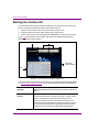
Starting the Intuition XG
Once the Intuition XG is properly racked and cabled, you can make the power connections
and you can perform the first-time start up of the Intuition XG unit.
1. Plug the monitor’s power cable into a power socket and power it on.
2. Plug the Intuition XG’s power supply cable(s) into a power socket.
3. Power on the Intuition XG unit by pressing the POWER button on the unit’s front panel.
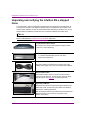
Figure 4-1 demonstrates that upon startup, the Intuition XG automatically displays the
desktop applications on the monitor.
Vertigo Command Shell
Intuition XG Control Panels
Intuition XG
Desktop Wallpaper
Xplay
Figure 4-1. The Intuition XG’s desktop applications
The following table provides briefly introduces each of the Intuition XG’s desktop applications.
The Intuition XG Configuration Guide provides further details regarding these applications.
Intuition XG desktop
wallpaper
The Intuition XG desktop wallpaper features the Intuition XG logo, as
well as identification information related to the specific Intuition XG
device.
Intuition XG Control
Panel(s)
Dual channel Intuition XG units (XG-Dual-e) will display two (2)
Control Panels (Channel A & Channel B), while on single channel
Intuition XG units (XG-e and XG-3U-e) will display only one.
The Control Panel is a simple user interface that allows you to
quickly reference general information about the Intuition XG device,
as well as perform basic tasks for operating the Intuition XG like,
loading a scene and launching the XG Dashboard application.
4-2
Intuition XG Installation & Quick Start Guide
Quick start instructions
Xplay
Xplay is the playout control application that the master control
system or device uses to control the playout of video and graphics
on the Intuition XG device.
Whether the Intuition XG is a single or dual channel model, only one
instance of Xplay is used to control the Intuition XG device’s output.
Vertigo Command
Shell
The Vertigo Command Shell window allows you to perform some
basic command tasks like opening Windows Explorer and
shutdown/reboot the Intuition XG device.
Intuition XG Installation & Quick Start Guide
4-3
Quick start instructions
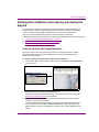
Assigning a new IP address to the Intuition XG device
Factory configured Intuition XG units are shipped with a dynamic IP address. Using DHCP
is not recommend, so you must assign a new static IP Address to the Intuition XG device.
To change the Intuition XG’s current dynamic IP address to a static IP address:
1. In the Vertigo Command Shell, type ipconfig and take note of the current IP configuration.
2. Again in the Vertigo Command Shell, type control to open the MICROSOFT CONTROL PANEL.
3. In the Microsoft Control Panel’s address bar, type 127.0.0.1 and press RETURN.
The INTUITION XG PORTAL’S log in page appears.
4. Type vertigo into the Password field and click the LOG IN button.
The INTUITION XG PORTAL web interface appears.
5.
Select the SETUP>NETWORK SETUP command to display the NETWORK SETUP page.
6.
Change the IP ADDRESS, SUBNET MASK, and DEFAULT GATEWAY values by typing the
new values in the corresponding text box.
Click the APPLY button.
A window appears asking you to confirm that you want to change the IP Address.
Click OK to restart the Intuition XG unit and apply the new IP Address.
7.
8.
4-4
Intuition XG Installation & Quick Start Guide
Quick start instructions
Verifying the installation and setup by previewing the
playout
To verify that the Intuition XG is properly connected and operating, we recommend that you
use the local copy of Xplay to load and playout an asset in the Live window and broadcast
monitor associated with the Intuition XG’s Channel A. For dual channel Intuition XG
devices, we recommend performing the same verification tasks on Channel B.
The following sections provide instructions for verifying the installation and setup of the Intuition XG:
1. “Verify the Intuition XG’s Output Resolution” on page 4-5
2. “Enable the Intuition XG’s Live window” on page 4-6
3. “Use Xplay to playout a graphic” on page 4-7
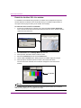
Verify the Intuition XG’s Output Resolution
Each of the Intuition XG’s output channels (Channel A and Channel B) have an Output
Resolution setting on their respective Dashboard, which determines the format of the
Intuition XG’s output signal.
To verify (and change) a Intuition XG’s output channel resolution:
1. In the Intuition XG’s Control Panel for Channel A, select the TOOLS>LAUNCH DASHBOARD
menu command.
2.
3.
Select the device’s channel from the Device List.
If the device is not listed in Dashboard’s Device List, perform a device discovery (see
Intuition XG Configuration Guide for instructions).
Verify the OUTPUT RESOLUTION setting. If the setting represents your desired output
resolution, continue to the next task.
If the Output Resolution setting is not what you desire, then select a different resolution
from the drop-down list and click the APPLY CHANGES button. When prompted, click
YES to apply the changes. Click YES again to restart the device, which applies the new
setting.
Intuition XG Installation & Quick Start Guide
4-5
Quick start instructions
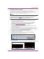
Enable the Intuition XG’s Live window
For installation and troubleshooting purposes, the Intuition XG is equipped with a preview
window called the Live Window. The Live Window allows you to display a representation of
the output channel’s playout directly on the Intuition XG’s desktop.
To enable the device channel’s Live Window:
1. If Channel A’s Dashboard is not already open, select the TOOLS>LAUNCH DASHBOARD
menu command in the Intuition XG’s Control Panel for Channel A. Then, select the device’s
channel from the Device List.
2.
3.
4.
5.
6.
Select ADVANCED from the Settings Mode drop-down list.
When promted, click YES to switch to advance mode.
Select the LIVE WINDOW tab and check the ENABLED box.
Click the APPLY CHANGES button. When prompted, click YES to apply the changes.
When prompted, click YES to perform a restart of the Intuition XG device.
Once the device has restarted, the Live Window will appear on the Intuition XG’s
desktop.
Live Window
NOTE
It is normal that the Live window is appears as double the expected width, since individual
fields are being displayed on a progressive PC output.
4-6
Intuition XG Installation & Quick Start Guide
Quick start instructions
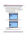
Use Xplay to playout a graphic
To verify that the Intuition XG is properly connected and playing out, the following
procedures has you add a template asset to the playlist, then cue and take the asset so that
it plays out in the Live window, as well as the broadcast monitor.
NOTE
These instructions describe playing out on the Intuition XG’s primary output (channel A). To
verify a dual channel Intuition XG’s second output (channel B), you must perform the same
setup and playout instructions (page 4-5), but using the Dashboard, Live Window,
broadcast monitor and Xplay device viewers associated with Channel B.
To verify the Intuition XG’s playout:
1. In Xplay, verify that the DEVICE 1 viewer’s LED is green, indicating that it is actively
connected to the Intuition XG’s channel A.
If the LED is red, double-click on the LED to connect to the device. If it still does not
change to green, verify that the device is properly configured in Xplay’s Device
Manager. See Intuition XG Configuration Guide for more information.
2. Verify that the DEVICE 1 Keyer is turned on (pink).
If the DEVICE 1 Keyer is turned off (grey), right-click on the DEVICE 1 Keyer and select
the TURN KEYER ON command.
3. Enable Xplay’s VERIFY PLAYLIST setting by selecting the TOOLS>SETTINGS menu command.
Select PLAYOUT and then verify that the VERIFY PLAYLIST setting is enabled. Click OK.
4. In the Asset Browser, select the TEMPLATES>DEMO_SAMPLES08>M11.
5. Double-click on any of the templates listed in the M11 category.
The template is added to the playlist.
6. Select the template in the playlist and click the CUE button in the Device Viewer.
The template is displayed in the Device Viewer.
7.
Click the TAKE button.
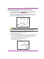
The graphic is played out on both the Intuition XG’s Live Window and the broadcast monitor.
Live Window
Intuition XG Installation & Quick Start Guide
Broadcast Monitor
4-7
Quick start instructions
Completing the quick start procedure
With the Intuition XG now capable of playing out graphics, we recommend that you disable the
Live Windows as they put an unnecessary burden on the system’s resources during on-air
playout.
Since the mouse, keyboard and DVI monitor are only used during the setup and configuration
procedures, you can also disconnect these peripherals from the Intuition XG unit.
To disable the Live Window:
1. If Channel A’s Dashboard is not already open, select the TOOLS>LAUNCH DASHBOARD
menu command in the Intuition XG’s Control Panel for Channel A. Then, select the device’s
channel from the Device List.
2.
3.
4.
5.
6.
7.
4-8
Select ADVANCED from the Settings Mode drop-down list.
When promted, click YES to switch to advance mode.
Select the LIVE WINDOW tab and clear (disable) the ENABLED box.
Click the APPLY CHANGES button. When prompted, click YES to apply the changes.
When prompted, click YES to perform a restart of the Intuition XG device.
On dual channel Intuition XG devices, repeat these steps for Output Channel B.
Intuition XG Installation & Quick Start Guide
5 NEED FURTHER ASSISTANCE?
Technical Support
For technical assistance, please contact the Miranda Technical support centre nearest you:
Americas
Telephone: +1-800-224-7882
e-mail: [email protected]
Asia
Telephone: +81-3-5644-7663
e-mail: [email protected]
Europe, Middle East, Africa, UK
Telephone: +44 (0) 1491 820222
e-mail: [email protected]
France (only)
Telephone: +33 (0) 1 55 86 87 88
e-mail: [email protected]
Related Documentation
To access the most recent updates to this document, or to access other Vertigo user
documentation, please visit the VERTIGO DOCUMENTATION section on MIranda’s TECHNICAL
SUPPORT SERVICES web site (http://support.miranda.com/).
Customer Service and Sales
For customer service or sales information, please contact a Miranda Technologies sales
office. Visit our web site at http://www.miranda.com/contact.php?link=worldwide to find
office nearest to you.
Intuition XG Installation & Quick Start Guide
5-1
Need further assistance?
Miranda’s Corporate headquarters
You can also contact Miranda’s corporate headquarters at:
Miranda Technologies Inc.
3499 Douglas-B.-Floreani
St-Laurent, Quebec, Canada H4S 2C6
Tel. 514-333-1772
Fax. 514-333-9828
www.miranda.com
5-2
Intuition XG Installation & Quick Start Guide