1
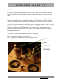
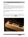
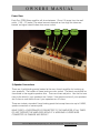
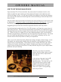
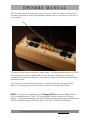
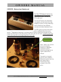
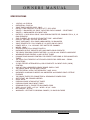
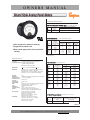
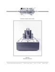
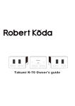
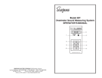
OWNERS MANUAL MANUAL NO. 01 REV. DATE: 1/2013 The ZEN TORII MONOS 1 Channel 60 watt Vacuum Tube Amplifier MODEL TORIIMONO Decware High Fidelity Engineering Co., East Peoria IL, USA www.decware.com OWNERS MANUAL QUICK START GUIDE - CHECKLIST Make sure you have the following items for each channel • Amplifier • PowerCord • 2 of the larger KT88 output tubes (8 pin) • 2 of the smaller 6N1P or 6922 input tubes (9 pin) 1) Install the tubes into the amplifier. Note: The large 8 pin tubes have a plastic center guide pin that fits into a notched keyway in the socket. It is important to figure out before installing the tube what the proper alignment should be. Once you get it to line up properly, the tube can be gently pushed into the socket until it seats. During both installation and removal it is important to install and remove the tubes in a straight in-and-out fashion with as little rocking as possible. The smaller 9 pin tubes are easier to see how to align and are plugged straight into the socket and removed by pulling straight out. These too should not be excessively rocked or tipped as it can damage the pins or even the socket. On 9 pin tubes it is important to visually inspect the pins to be sure they are straight. Since the pins are smaller in diameter they are easy to bend and are often slightly bent from handling. These pins can be carefully straightened by hand or you can purchase a tube pin straightener from most tube suppliers that makes the task quick and simple. Installing 9 pin tubes with pins that are not straight will damage the socket of the amplifier, an item not easily replaced since the main circuitry is directly soldered to the socket pins. Another note about tubes and straight pins is this: Many tubes, being blown glass and assembled by hand, are not perfectly straight relative to the base of the tube and or tube pins. It is common for some tubes to be slightly crooked. This has nothing to do with how straight the pins of the tube are and should be treated as a separate issue which is purely cosmetic. The ideal way to clean tube pins is with a pencil eraser, and it’s a good idea to clean even new tubes prior to plugging them into your amp. It is acceptable to use FINITE amounts (perhaps 1 drop for all 8 or 9 pins) of “Caig DeOxit” products to further clean and lubricate the tube sockets. Apply product to tube pins only. A small amount of this has already been applied at the factory and should last at least a year. Decware High Fidelity Engineering Co., East Peoria IL, USA www.decware.com OWNERS MANUAL Tube Locations As you can see in the picture below, the two larger tubes go into the 8 pin sockets. The tubes should be matched and it makes no difference which one goes on what side. The two smaller 9 pin tubes are of the same type. They are either 6N1P or 6922, often supplied in matched pairs, meaning both tubes are of the same type. If this is the case, then it makes no difference which tube goes in the front or the back position. If you plan to get creative and try mixing it up a bit, by installing one of each, the front tube is likely to have the biggest impact on the sound. The rear tube is what we call a follower so it adds no gain to the signal, just a lot of torque. Often we see users placing a 6922 in the front location and a 6N1P in the rear location but reversing it changes the sound too. The sound of these interchangeable tubes are as follows: 6N1P - warmest, smoothest, most forgiving 6922 - slightly less warm, more dynamic, tighter focus KT88 KT88 KT88 6N1P/6922 6N1P/6922 Decware High Fidelity Engineering Co., East Peoria IL, USA www.decware.com OWNERS MANUAL 2) Install Power Cord Each amplifier has a high quality IEC connector. This is an overlooked item on most amplifiers and are typically made in China with inferior plastics, metals, and feature poor electrical connections and earth grounds that change with tension, and temperature. This includes the gold plated ones being sold to unknowing audiophiles at an inflated price. Our power cord connector, being quite the opposite, is fully worthy of an expensive power cord. Note: Having the power cord go straight up and then curve straight down, relieves the leverage on the contacts inside the power cord which in turn prevents it from prematurely wearing out. Fuse The IEC connector where the power cord plugs into has a concealed door that can be pried open to reveal the fuse holder. Inside it there is also a spare fuse. The fuse should be a 20x5mm with a maximum rating of 5 amps. If you have a 240VAC model your fuse should be 2.5 amps. Fast Blow types are recommended. Decware High Fidelity Engineering Co., East Peoria IL, USA www.decware.com OWNERS MANUAL Power Draw Each Zen TORII Mono amplifier will draw between 1.2 and 1.6 amps from the wall outlet. (150 ~175 watts) The actual amount depends on how high the tubes are biased, as higher biased tubes draw more current. Neg 4 ohm 8 ohm 16 ohm 3) Speaker Connections There are 4 gold binding posts located at the rear of each amplifier for hooking up your speakers. The bottom of these jacks are color coded. The black one should be connected to the negative speaker wire. There are three red jacks. Use the first one (next to the black) if your speakers are 4 ohms. Use the second one if your speakers are 8 ohms or use the third one if your speakers are 16 ohms. These are industry standard 5 way binding posts that accept bare wire up to 8 AWG, spade connectors or banana jacks. MAKE SURE A LOUDSPEAKER IS CONNECTED TO THE AMPLIFIER AT ALL TIMES. DO NOT OPERATE THE AMPLIFIER WITHOUT A WORKING LOUDSPEAKER CONNECTED AS DAMAGE MAY RESULT. Decware High Fidelity Engineering Co., East Peoria IL, USA www.decware.com OWNERS MANUAL STARTING YOUR AMPLIFIER FOR THE FIRST TIME Once you have the tubes installed and the power cord plugged in, the volume control all the way down (counter-clockwise) you are almost ready to turn it on. BEFORE YOU DO, we need to familiarize you with the BIAS controls. There are only two and they are extremely easy to operate. (after the amplifier is turned on and properly biased, we will connect your source component.) We’ll start with the most important of the two controls, the one in the front of amplifier located between the two meters. It is a small 1/4 inch shaft with no knob on it. The knob is not used because this control is seldom adjusted, and a knob makes it easier to accidentally bump it out of adjustment. This control is called the BIAS BALANCE KNOB and it is simply used to make the two meters read the same value. In the picture above you can see the meter on the left is for the KT88 output tube directly behind it. Same for the meter on the right. These meters show how many milliamps of current are going through each output tube. Since this is a push pull amplifier, the objective is to get both tubes to draw the same amount of current so that they match. This gives the best performance and the most power. Decware High Fidelity Engineering Co., East Peoria IL, USA www.decware.com OWNERS MANUAL HOW TO USE THE BIAS BALANCE KNOB Approximately 30 to 40 seconds after the power switch has been turned on, the heaters inside the output tubes (part that glows) will begin to emit electrons and current will begin to flow. You will want to watch this happen in real time by keeping your eyes on the meters and watching them climb and seeing if the both stop at the same number. After the tubes heat up the meters will show how many milliamps of current each tube is adjusted to. If they don’t match, simply adjust the control until they do. If you turn the control the wrong way, the difference between the two meters will increase suggesting that you turn the control the opposite direction until they match. As the tubes heat up during the first 15 to 30 minutes, you’ll see the current draw of each tube drift a bit. This is normal and requires only another fine adjustment to get the tubes balanced and then expect them to stay that way until you turn the amplifier off. When you turn it on again for your next listening session, you’ll find the tubes will bias up right where you had them set once they have fully warmed up. Of course you can make fine adjustments at any time, and if music is playing, just turn the volume control all the way down to make your adjustment. Later on you will notice that music effects the meters at higher volume levels. In fact the meters can dance pretty readily when the amplifier is at it’s maximum 60 watt output level on musical peaks. That means you can visually SEE when your amp is running out of power and starting to distort. Keeping your amp from making the meters move excessively (more than 20 mills) ensures long life for your output tubes, speakers and your hearing. Now that your amp is on and the meters read the same value on each side, lets learn how to adjust what that value is. In the picture, the amp is set to 60 mills per side. This is an ideal operating point. You can run it at 70 mills per side which tends to add weight to the sound but you may think is sounds better at 60 mills. There is no right or wrong setting, just trust your ears. Decware High Fidelity Engineering Co., East Peoria IL, USA www.decware.com OWNERS MANUAL After the bias meters are balanced, you can raise or lower the value of them both at the same time without loosing the balance between them via this control at the rear of the amplifier. The range of this control varies with output tubes. The ideal operating point for KT88’s in this amplifier would be between 60 and 70 milliamps. 80 milliamps should be considered the absolute maximum. Running any higher will sacrifice headroom and create more heat. This control may be operated while music is playing at normal listening levels or below. It is common to set this control every time you change output tubes. NOTE: This amp is compatible with the Tungsol KT120 power tubes IF the bias is run at the lowest setting. The KT120 tube causes the bias window to shift much higher. On the lowest setting it will read 80 milliamps whereas the same setting would read 50 milliamps when a KT88 was used. Run the KT120’s at 80 milliamps. Decware High Fidelity Engineering Co., East Peoria IL, USA www.decware.com OWNERS MANUAL Summary of quick start up You’re going to hook up your speakers, properly install the tubes and power cord, plug the amplifier in, turn the volume control all the way down, and turn on the amp. You’ll watch the bias meters as the tubes start to glow and within a minute or less you’ll see them register the current of each output tube. Adjust the control so they match. NOISE Check At this point, the amp is on with a speaker hooked to it and the volume is turned all the way down. This is called “idle” and you should hear no sound from your speakers. No hum, no hiss, no noise that would be detectable from the listening chair. To hear anything at all you should have to put your head around 6 to 12 inches away from the speaker. Source hookup - it is important from this stage forward to pay attention to the residual noise floor that we have established in the noise check above. If it increases in any way as we hook up the source component(s) then we know the cables or source components are the cause. The next step is to hook up your source, and this can be done with the amplifier on or off, but in both cases, the volume control on the amplifier should always be turned down as far as it will go while you are hooking up the source cables. If you have balanced sources then use the balanced XLR input jacks, if not, then use the RCA unbalanced input jack. Once connected, with your source paused, you can slowly raise the volume control and check for noise. If everything seems satisfactory, then return the volume control the off position, and un-pause your source and slowly raise the volume to the desired level. Decware High Fidelity Engineering Co., East Peoria IL, USA www.decware.com OWNERS MANUAL SOURCES - Balanced and Unbalanced The Zen TORII Mono’s feature two fully balanced XLR input jacks and one single-ended (unbalanced) RCA input jack. The two XLR jacks are selectable via a switch on the front half of the amplifier so that you can potentially have a feed from two different sources and select between them. The RCA jack is active all the time and is unaffected by the source switch. That means that even if you have the XLR jacks hooked up, as soon as you plug in the RCA jack it will take priority and that is all you will hear. The RCA jack must not be shorted with a shorting plug when not in use. Source Switch Note: Select your source prior to turning the amplifier on because access the switch without touching the hot output tubes will be difficult. The switch is located here for sonic reasons. Behind the switch are the two Jensen Input Transformers that connect to the XLR jacks. Decware High Fidelity Engineering Co., East Peoria IL, USA www.decware.com OWNERS MANUAL Source switch - continued. When looking at the amplifier from the front, as in the picture on the previous page, moving the source switch towards you will select the XLR jack on the right, which is the one directly next to the RCA jack. Moving the source switch to the rear position selects the other XLR jack. After you have your source connected to the amplifier and music playing, slowly raise the volume control on the front to the desired listening level. Preamps If you plan to use a preamp, you will end up with basically a volume control on the preamp and a gain control on the amplifier. This is a huge advantage over having an amplifier without a gain control. You’ll want to experiment with where best to set the gain control on the amplifier. Start with it set all the way up - same thing as not having a gain control. Then experiment with turning the gain control down and the volume control on the preamp up to compensate. You’ll find this adjustment can have a big effect on the sound. Just go with what works and sounds best to you. Remember, the audio chain can be no more transparent than the weakest link in the chain... sometimes this can be a preamp. The way to tell is to listen to the amps with and without a preamp and see if there is a detectible veil over the music when the preamp is used. OUTPUT TUBE MATCHING TIPS The meters on this amplifier can be used to see tubes age and monitor their performance. If you find that you have to adjust the bias balance control almost all the way to one side to achieve balance that means the tubes no longer match in so much as one has become weaker in output than the other. This would be a good time to replace the tubes. Don’t be fooled! The input tube (small 9 pin tube closest to the front of the amplifier) is of critical importance to the matching of the output tubes. It too must be reasonably well matched from side to side (the small tubes actually have two sections inside them whereas the large output tubes have only one section inside). If you find yourself have unexplained trouble getting output tubes to match, or the meters dance wildly when music is played it is an indication that the front input tube should be replaced. Once replaced, the output tubes may balance up fine. Decware High Fidelity Engineering Co., East Peoria IL, USA www.decware.com OWNERS MANUAL OPERATION If you’ve been going through this manual (highly highly recommended) and reached this point, we know you’re already listening to music and we’ll probably never see you again... but a few additional notes... TYPE OF AMP Your Class A amplifiers are a push-pull design with an adjustable fixed bias using ultralinear output transformers with multiple taps for different loudspeakers. It is a design with the fewest internal parts of any push pull amplifier featuring direct coupled stages for maximum transparency and minimal phase angle. SAFTEY Your amplifiers are fused, however with all devices that generate heat it is not recommended to leave the amplifier on when you are not at home, or during the night when you are sleeping. There are no internal user serviceable parts inside this amplifier. OPTIONS Your amplifier comes with a pair of Jensen JT11P1 balancing transformers to cover most applications, however, any of the balancing transformers Jensen makes can be requested for custom applications in recording studio environments. Decware High Fidelity Engineering Co., East Peoria IL, USA www.decware.com OWNERS MANUAL SPECIFICATIONS • • • • • • • • • • • • • • • • • • • • • • • • • • • • • • • • • 120/240 volt 50/60Hz OPERATION: CLASS A1 INPUT TUBE CHOICES: 6922, 6N1P OUTPUT TUBE CHOICES: EL34 6CA7 KT77 6550 KT88 INPUTS: 2 BALANCED XLR INPUT JACKS FOR EACH CHANNEL - SELECTABLE INPUTS: 1 UNBALANCED RCA INPUT JACK OUTPUTS: 1 PAIR HEAVY GOLD 3 WAY BINDING POSTS PER CHANNEL FOR 4, 8, 16 OHM SPEAKERS IDLE CURRENT: 50~90 MILS PER OUTPUT TUBE - ADJUSTABLE HIGH B+ VOLTAGE: 510 VDC WITH LOAD INPUT IMPEDANCE: 38 K OHMS UNBALANCED 13K BALANCED INPUT SENSITIVITY: FULL POWER @ 2.0 VOLTS ON RCA INPUT POWER INTO 4 , 8 or 16 OHMS: 58.6 WATTS PER CHANNEL NOISE: -90dB SILVER CONTACTS on SOURCE SWITCH MACHINED OUTPUT SOCKETS WITH MACHINED GOLD CONTACTS TOP GRADE SIMPSON CURRENT METERS 0 to 100 MA with JEWELED MOVEMENT WINDOWED BIAS CONTROL to ADJ OUTPUT TUBES DYNAMIC BIAS BALANCE CONTROL FOR PERFECT MATCHING of EVEN UNMATCHED TUBES 1UF 600V CRYO TREATED FLAT STACKED COPPER FOIL BEES WAX - SIGNAL CAPACITORS 20 POS STEPPED ATTENUATOR w/ GOLD CONTACTS for INPUT LEVEL (GAIN) CONTROL 4400 UF 500V LABORATORY GRADE POWER SUPPLY CAPS TOP GRADE GOLD TEFLON INPUT JACKS RECTIFICATION: ULTRA FAST RECOVERY 3 AMP 1000V MACHINED ALUMINUM CHASSIS with ANODIZED and POWDER COAT LIFETIME FINISHES TOP GRADE FUSED IEC CONNECTOR for REMOVABLE POWER CORD SOFT START- NO STANDBY NEEDED SHIPS WITH: PREMIUM GRADE KT88 OUTPUT TUBES PREMIUM GRADE 6N1P INPUT TUBES REMOVABLE DHC-1 SILVER TEFLON POWER CORD SIZE: 19-1/8 " DEEP x 13-3/4 " WIDE x 8-3/4 " HIGH NET WEIGHT: 36.8 lbs. WARRANTY: LIFETIME TO ORIGINAL OWNER / 90 DAYS ON TUBES Decware High Fidelity Engineering Co., East Peoria IL, USA www.decware.com OWNERS MANUAL JT-11P-1 LINE INPUT TRANSFORMER 1:1 FOR "BALANCED BRIDGING" INPUTS M M M M M Ideal for balancing any high-impedance unbalanced input Wide bandwidth: !3 dB at 0.25 Hz and 95 kHz Recommended for levels up to +20 dBu at 20 Hz High input impedance: 13 kS S with 10 kS S load High common-mode rejection: 107 dB at 60 Hz This transformer is designed for use in wideband line input stages. Distortion remains very low and CMRR remains high, even when driven by high source impedances. The primary is fully balanced and its leads may be reversed to invert polarity, if required. A 30 dB magnetic shield package is standard. TYPICAL APPLICATION Decware High Fidelity Engineering Co., East Peoria IL, USA www.decware.com OWNERS MANUAL Ordering Information AC Microammeters Rectifier Type, Self Shielding Movement Range Model/Size and Catalog Number Approx. Impedance (ohms) 3-1/2” Model 45 04080 3400 0-100 AC Milliammeters, Iron Vane & Rectified Movement Model/Size and Catalog Number • Glass window for optimum viewing • Rugged black plastic case • Black spade-type pointer for easy distant reading Range 0-1 0-5 0-10 0-15 0-100 0-150 0-250 0-500 Approx. Impedance (ohms) @ 60 Hz 600 200 887.0 80.0 717.2 8.76 3.1 .9 2-1/2" Model 155 <> <> <> <> <> <> 06080 <> 3-1/2" Model 55 <> <> 05380 05400 05410 35069 05420 05430 4-1/2” Model 45 06820* 06840* <> <> <> <> <> <> * Rectified Models Specifications Accuracy: ±2% F.S. (Iron-Vane), ±3% F.S. (Rectifier) Frequency models: 45-55Hz ±0.3Hz (120V-240V) 55-65Hz ±0.3Hz (120V-240V) 380-420Hz ±1.2Hz (120V-240V) Wattmeters: +2% F.S.; Compensated Meters: +3% F.S. Movement: Models 55, 155: Iron-vane, magnetically damped Models 45, 145: Annular, rectifier type Models 85 & 185: small core magnet, self-shielding Models 25, 27, 29, 125: Annular, self-shielding Tracking: Shielding: Response Time: Overload (1 sec.): Overload (Continuous): Repeatability: Dial: ±3% Calibration is unaffected by magnetic panel mounting. 1.5 seconds maximum 10 times F. S. Case: Resistance: Operating Temp: Pointer: Scale Length: Net Weight: 1.5 times F. S. 2% Sharp clear scale. Each dial arc is calibrated to track the specific type of movement used. High density black plastic ±15% -4°F to +149°F (-20°C to +65°C) Models 85 & 185: knife edge, black finish All others: spade pointer with black matte finish Model 155 & 185: 1.6” (40.6mm) Models 125 & 145: 1.8” (45.7mm) Model 55: 2.3” (58.4mm) Models 25, 27, 45 & 85: 2.5” (63.5m) Model 29: 3.80” (96.5mm) Models 55, 155 & 185: 5oz (0.14kg) Models 85, 125, 145 & 45: 7oz (0.20kg) Models 25 & 27: 8oz (.23kg) Model 29: 11oz. (.31kg) AC Ammeters, Iron Vane Movement Range 0-1 0-1.5 0-2 0-3 0-5 0-10 0-15 0-25 0-30 0-50 0-75 0-75 0-100 0-150 0-200 0-250 0-300 0-500 Approx. Impedance (ohms) @ 60 Hz .213 .105 .065 .028 .008 .004 .0025 .002 .0015 .001 .0002 .008 .008 .008 .008 .008 .008 .008 Model/Size and Catalog Number 3-1/2" 2-1/2" Model 55 Model 155 00950 02100 00960 <> 00970 02120 00980 02130 00990 02140 01001 02150 01010 02160 01020 02170 01030 02180 01040 02190 03432 <> <> 02200* 01060* 02210* 01070* 02220* 01080* <> 01090* 02240* 01100* <> 01110* 02260* <> Available on special order. * These meters require use of an external current transformer from page C4-C6 4-2 20mA Process Meters, Dial indicates 0-100 Percent Range Approx. Impedance (Ohms) Model/Size and Catalog number 3-1/2” Model 25 4-20 5.0 35022 more >> For more information, visit www.simpsonelectric.com Decware High Fidelity Engineering Co., East Peoria IL, USA www.decware.com OWNERS MANUAL RoHS ALS30 Series 85°C • • • • • Compliant Compact size Long life, 20000 hours at 85°C (Ur, Ir applied) High ripple current Excellent surge voltage capability Optimized designs available on request APPLICATION BASIC DESIGN Smoothing, energy storage, or pulse operation in telecommunication demanding power supplies, process control, AC-motor control, traction, welding and measuring. The ALS30/31 series of screw terminal capacitors cover a wide range of case sizes and voltage ratings featuring high ripple currents and long life performance. They are ideally suited for industrial and commercial applications demanding high reliability and long life expectancy such as frequency converters, UPS systems and switch mode power supplies. SPECIFICATION Standards IEC 60384-4 Long Life Grade 40/85/56, Capacitance range 100 – 680000 µF Capacitance tolerance –20 to +20% Rated voltage UR 25–500 VDC Surge voltage US 1.15 x UR (for UR < 250 VDC) 1.10 x UR (for UR > 350 VDC) Surge voltage USS (Short duration) Leakage current IL Operational life time +85°C, UR , IR +85°C, UR UR USS 200 250 350 400 415 450 500 350 400 500 520 530 550 600 Test Condition: < 30s surge, 1000 cycles @ 85°C Test Condition: < 500ms surge, 100 cycles @ 20°C = 0.006 x CR x UR (µA) or 6mA whichever is the smaller. Note, CR is in µF. Can Diameter 36 51 66 77, 90 11000 hrs 18000 hrs 19000 hrs 20000 hrs Can Diameter 36 51 66 77, 90 22000 hrs 36000 hrs 38000 hrs 40000 hrs Shelf Life 2000 hrs at 0V +85°C, or 30000 hrs at 0V +40°C Temperature range –40 to +85°C (Operating) -55°C to +85°C (Storage) Test Condition: UR, 5mins., 20°C End of Life requirement: C/C ESR IL < ±10% < 2 x initial ESR value < initial specified limit Decware High Fidelity Engineering Co., East Peoria IL, USA www.decware.com OWNERS MANUAL TECHNICAL QUESTIONS or SERVICE: DECWARE / High Fidelity Engineering Co. 75 S. Riverview Dr. East Peoria, IL 61611 309 822 5255 [email protected] - technical [email protected] - service Decware High Fidelity Engineering Co., East Peoria IL, USA www.decware.com OWNERS MANUAL Added Notes: BIASING - There are some important additional notes about biasing and output tubes that you should understand. First is the bias “window”. This means “range of adjustment” and primarily concerns the rear bias control next the power cord jack on your TORII Mono’s. We have tried to define a window where the lowest bias setting you can achieve is 45 milliamps and the highest setting is 75 milliamps. This was done in an attempt to make it impossible to make adjustments that can either hurt the tubes or the amplifier. Unfortunately there are two main variables that can have a large effect on this bias window. They are A) The tubes used and B) the voltage at your wall outlet or power conditioner. A) We ship these amplifiers with KT88 output tubes. The two favorites are JJ and ElectroHarmonix. Pending the tube’s specs and age, these tubes can cause your amplifier’s bias window to shift UP or DOWN. B) Depending on the voltage at your wall outlet, which may vary during the day or when your electric heat kicks on during the winter months, the bias window of your amplifier can shift UP or DOWN. In this case, the window tends to follow the voltage. If the voltage is low (113 Volts) you may see the window move down several milliamps. If the voltage is high (125 Volts) you may see the window move up by several milliamps. The combination of both A and B can cause the bis window to move by as much as 20 milliamps. For example, a fresh pair of KT88’s may bias up with the minimum adjustment of 60 milliamps and a maximum of over 80 milliamps when the amp is plugged into an outlet when the voltage is on the high side (125V). The same amp, with a used pair of KT88’s when the voltage at the wall outlet is on the lower side (113V) could cause the minimum adjustment to be 40 milliamps and the maximum to be 60 milliamps. THE ONLY THING TO REMEMBER REALLY IS THIS: The speed limit is 80 milliamps. Try not to go over this amount. The ideal bias setting is between 58 milliamps and 72 milliamps. Try to keep it somewhere between these two figures. Decware High Fidelity Engineering Co., East Peoria IL, USA www.decware.com