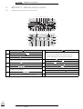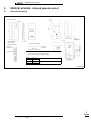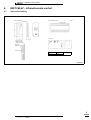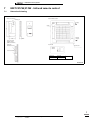
1
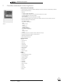
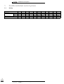
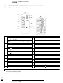
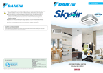
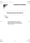
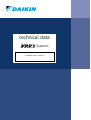
technical data
Systems
Individual control systems
• Individual control systems
Individual control systems
1
16
Possible individual control systems
Survey..........................................................................................................................................................................4
2
BRC2A51 - Simplified remote control
Explanation of buttons and functions...................................................................................................5
3
BRC3A61 - Simplified remote control for hotel applications
Dimensional drawing ........................................................................................................................................6
Explanation of buttons and functions...................................................................................................7
4
BRC1D517 - Wired remote control
Dimensional drawing ........................................................................................................................................8
Explanation of buttons and functions...................................................................................................9
5
BRC4C61,62,63,64 - Infrared remote control
Dimensional drawing .....................................................................................................................................11
Explanation of buttons and functions................................................................................................12
6
BRC7C62,67 - Infrared remote control
Dimensional drawing .....................................................................................................................................13
Explanation of buttons and functions................................................................................................14
7
BRC7C512W,513W - Infrared remote control
Dimensional drawing .....................................................................................................................................15
Explanation of buttons and functions................................................................................................16
8
BRC7E531W,530W - Infrared remote control
Dimensional drawing .....................................................................................................................................17
9
BRC7E63W,66 - Infrared remote control
Dimensional drawing .....................................................................................................................................18
Explanation of buttons and functions................................................................................................19
10
BRC7E618,619 - Infrared remote control
Dimensional drawing .....................................................................................................................................20
11
•
Survey of various control systems.......................................................................... 21
Systems • Control Systems
1
• Individual control systems
1
Possible individual control systems
Simplified remote control - BRC2A51
• simple, compact and easy to operate unit
Simplified remote control for hotel
applications - BRC3A61
• compact, user friendly unit
Infrared remote control BRC4C* / BRC7C*
•
• suitable for use in hotel bedrooms
Operation buttons:
• ON / OFF
• ideal for use in hotel bedrooms
Operation buttons:
• ON / OFF
Operation buttons:
• ON / OFF
• Operation mode selection
• Fan speed control
• Timer mode start / stop
• Fan speed control
• Temperature setting
• Timer mode on / off
• Temperature setting
• Programmed time
• Temperature setting
• Air flow direction (FXHQ, FXFQ, FXCQ and FXAQ models only)
• Operating mode
• Fan speed control
• Filter sign reset
Display
• Cool / heat changeover control
Display
• Heat Recovery Ventilation (HRV) in operation
• Inspection test / operation
Display
• Operating mode
• Heat Recovery Ventilation (HRV) in operation
• Set temperature
• Battery change
• Set temperature
• Operating mode
• Set temperature
• Operating mode
• Centralised control indication
• Air flow direction (FXHQ, FXFQ, FXCQ and FXAQ models only)
• Centralised control indication
• Fan speed
• Programmed time
• Fan speed
• Defrost / hot start
• Inspection test / operation
• Defrost / hot start
• Malfunction
• Fan speed
• Malfunction adjustment
• Operating mode selection
• Fan speed control
• Filter sign reset
• Inspection test / operation
1
2
•
Systems • Control Systems
• Individual control systems
1
Possible individual control systems
Wired remote control - BRC1D517
• Limit operation (min./max.): room temperature is controlled within adjustable upper and lower limits. Limit operation can be activated manually or by schedule timer
• Real time clock: indicates real time and day
• Schedule timer:
– -It is possibie to programme a weekly schedule timer
– -It is possible to programme the remote control for each day of the week. Five day actions can be set as follows:
– -set point: unit is switched ON and normal operation is maintained
– -OFF: unit is switched OFF
– -limits: unit is switched ON and min./max. control (cf.limit operation for more details)
• Home leave (frost protection): during absence, the indoor temperature can be maintained at a certain level. This function can also switch the unit ON/OFF
• Different levels of disabled buttons can be selected as follows:
– level 1: all buttons are accessible
– level 2: all buttons are disabled except for:
–ON/OFF
–set temperature up/down
–fan speed
–cooling/heating mode
–enable/disable schedule timer
–air flow direction adjustment button
– Level 3: all buttons are disabled except for:
–ON/OFF
–set temperature up/down
–fan speed
• User friendly HRV function, thanks to the introduction of a button for ventilation mode and fan speed
BRC1D517
• Constantly monitoring of the system for malfunctions in a total of 80 components
• Immediate display of fault location and condition
• Reduction of maintenance time and costs
Operation buttons:
• ON / OFF
• Timer mode start / stop
• Timer on / off
• Programmed time
• Temperature setting
• Air flow direction adjustment
• Operating mode selection
• Fan speed control
• Filter sign reset
• Inspection test / operation
Display
• Operating mode
• Heat Recovery Ventilation (HRV) in operation
• Cool / heat changeover control
• Centralised control indication
• Group control indication
• Set temperature
• Air flow direction
• Programmed time
• Inspection test / operation
• Fan speed
• Clean air filter
• Defrost / hot start
• Malfunction
1
•
Systems • Control Systems
3
• Individual control systems
1
Possible individual control systems
1-1
Survey
DESCRIPTION
Wired remote control
Infrared remote control
Simplified remote control
Simplified remote control for hotel use
cooling only
heat pump
FXZQ
FXFQ
FXCQ
FXKQ
FXSQ
BRC7E531W
BRC7E530W
-
BRC7C513W
BRC7C512W
-
BRC7C67
BRC7C62
-
BRC4C63
BRC4C61
-
BRC4C64
BRC4C62
BRC2A51
BRC3A61
•
Systems • Control Systems
1
4
FXDQ
BRC1D517
BRC4C64
BRC4C62
BRC2A51
BRC3A61
FXMQ
FXHQ
FXAQ
FXLQ
FXNQ
BRC4C64
BRC4C62
BRC2A51
BRC3A61
BRC7E66
BRC7E63W
-
BRC7E619
BRC7E618
-
BRC4C64
BRC4C62
BRC2A51
BRC3A61
BRC4C64
BRC4C62
BRC2A51
BRC3A61
• Individual control systems
2
BRC2A51 - Simplified remote control
2-1
Explanation of buttons and functions
1
2
ON/OFF BUTTON
Press the button and the system will start. Press the button again and the system will stop.
OPERATION LAMP (RED)
4
5
7
“,”
”,”OPTION” (VENTILATION / AIR CLEANING)
DISPLAY ‘
C ’ (SET TEMPERATURE)
This display shows the set temperature. Only given during a cooling or heating operation.
’‘
’‘
’‘
’‘
’ (OPERATION MODE)
This display shows the current OPERATION MODE.
‘
’ is not available with outdoor units specially designed for cooling only.
‘
’ is reserved only for outdoor units capable of heat recovery.
DISPLAY ‘
’ (FAN SPEED)
The display shows the fan speed: “HIGH” or “LOW”.
’ (DEFROST/HOT START)
Indicates that defrost or hot start (during which the fan is stopped till the temperature of air supply rises enough
at the start of a heating run) is in progress.
TEMPERATURE SETTING BUTTON
Use this button for SETTING TEMPERATURE of the thermostat.
10
▲; Each press raises the set temperature by 1°C.
▼; Each press lowers the set temperature by 1°C.
This display shows that the total heat exchange unit and the air cleaning unit are in operation. (These are optional
accessories.).
DISPLAY ‘
6
9
‘ (CHANGEOVER UNDER CONTROL)
It is impossible to changeover heat/cool with the remote controller when it shows this display. (As for details, see
“SETTINGS OF MASTER REMOTE CONTROL” in the operation manual attached to the indoor unit.).
DISPLAY “
DISPLAY ‘
DISPLAY ‘
The lamp lights up during operation and blinks in case of stop due to malfunction.
DISPLAY ‘
3
8
The variable temperature range is 16°C tot 32°C.
11
12
FAN SPEED CONTROL BUTTON
Press this button to select the fan speed, HIGH or LOW, of your choice.
OPERATION MODE SELECTOR BUTTON
Press this button to select OPERATION MODE.
DISPLAY ‘
13
’ (UNDER CENTRALIZED CONTROL)
’ (MALFUNCTION)
Indicates malfunction and blinks if the unit stops operating due to the malfunction.
(As for details, see “TROUBLE SHOOTING” in the operation manual attached to the indoor unit.)
When this display shows, the system is UNDER CENTRALIZED CONTROL. (This is not a standard specification)
NOTE
1
Please note that the display shows all indications for the purpose of explanation only.
This is contrary to actual running situations.
2
•
Systems • Control Systems
5
• Individual control systems
3
BRC3A61 - Simplified remote control for hotel applications
3-1
Dimensional drawing
(Unit: mm)
2 - 5 x 9 Slot
(Fixing hall)
BRC3A61
FXSQ
FXMQ
FXDQ
FXLQ/FXNQ
3D013859A
3
6
•
Systems • Control Systems
• Individual control systems
3
BRC3A61 - Simplified remote control for hotel applications
3-2
Explanation of buttons and functions
1
ON/OFF BUTTON
7
Press the button and the system will start. Press the button again and the system will stop.
OPERATION LAMP (RED)
2
3
DISPLAY ‘
8
The lamp lights up during operation or blinks if a malfunction occurs.
DISPLAY “
“,”
” (VENTILATION / AIR CLEANING)
This display shows that the total heat exchange unit is in operation.
5
6
DISPLAY ‘
’ (FAN SPEED)
’ (DEFROST/HOT START)
Indicates that defrost or hot start (during which the fan is stopped till the temperature of air supply rises enough
at the start of a heating run) is in progress.
TEMPERATURE SETTING BUTTON
Use this button for SETTING TEMPERATURE of the thermostat.
(These is an optional accessory).
4
DISPLAY ‘
The display shows the set fan speed: ‘HIGH’ or ‘LOW’.
9
▲; Each press raises the set temperature by 1°C.
▼; Each press lowers the set temperature by 1°C.
C ’ (SET TEMPERATURE)
This display shows the set temperature. Only given during a cooling or heating operation.
The variable temperature range is 16°C tot 32°C.
DISPLAY ‘
FAN SPEED CONTROL BUTTON
’‘
’‘
’‘
’‘
’ (OPERATION MODE)
This display shows the current OPERATION MODE.
‘
’ is not available with outdoor units specially designed for cooling only.
‘
’ is reserved only for heat recovery outdoor units.
DISPLAY ‘
10
Press this button to select the fan speed, HIGH or LOW, of your choice.
DISPLAY ‘
11
’ (UNDER CENTRALIZED CONTROL)
’ (MALFUNCTION)
Indicates malfunction and blinks if the unit stops operating due to the malfunction.
(As for details, see “TROUBLE SHOOTING” in the operation manual attached to the indoor unit.)
When this display shows, the system is UNDER CENTRALIZED CONTROL. (This is not a standard specification)
NOTES
1
2
Please note that the display shows all indications for the purpose of explanation only.
This is contrary to actual running situations.
This remote controller does not have “AIR FLOW DIRECTION ADJUST BUTTON.” Don’t operate the flap adjusting air flow direction by your hand.
(FXFQ, FXCQ, FXAQ, FXKQ)
3
•
Systems • Control Systems
7
• Individual control systems
4
BRC1D517 - Wired remote control
4-1
Dimensional drawing
(Unit: mm)
5 x 10 (Round end slit)
6,5 x 9 (Round end slit)
5 x 7 (Round end slit)
Hole ø5
Cover closed
Cover open
3TW23651-2
4
8
•
Systems • Control Systems
• Individual control systems
4
BRC1D517 - Wired remote control
4-2
Explanation of buttons and functions
3
6
23 7
8
9
2
1
10
4
11
12
14
22
17
25
16
13
15 18
19
20
29
21
5
24
33
26
35
27
36
37
28
1
2
3
4
ON/OFF BUTTON ‘
31
’
OPERATION LAMP ‘
’
14
The operation lamp lights up during operation or blinks if a malfunction occurs.
OPERATION MODE ICON ‘
’‘
’‘
’‘
’‘
’
These icons indicate the current operation mode (FAN, DRY, AUTOMATIC, COOLING, HEATING).
VENTILATION MODE ICON ‘
’,’
32
13
Press the ON/OFF button to start or stop the system.
’,’
’
These icons indicate the current ventilation mode (HRV only) (AUTOMATIC, HEAT EXCHANGE, BYPASS).
VENTILATION ICON‘
5
30
’
The ventilation icon appears when the ventilation is adjusted with the ventilation amount button (HRV only).
15
16
17
Simultaneously, the ventilation amount is indicated by the fan speed icon (see 22).
6
AIR CLEANING ICON ‘
18
’
’
19
The leave home icon shows the status of the leave home function.
7
ON
FLASHING
OFF
Leave home is enabled
Leave home is active
Leave home is disabled
20
21
8
EXTERNAL CONTROL ICON ‘
11
12
‘
This icon indicates that the change-over of the installation is under centralised control assigned to another indoor
unit or optional cool/heat selector connected to the outdoor unit (= master remote controller).
DAY OF THE WEEK INDICATOR ‘
10
‘
The day of the week indicator shows the current week day (or the set day when reading or programming the
schedule timer).
CLOCK DISPLAY ‘
22
23
24
25
‘
The clock display indicates the current time (or the action time when reading or programming the schedule timer).
MAXIMUM SET TEMPERATURE ‘
C
‘
The minimum set temperature indicates the minimum set temperature when in limit operation.
SCHEDULE TIMER ICON ‘
‘
This icon indicates that the schedule timer is enabled.
ACTION ICONS ‘
‘
These icons indicate the actions for each day of the schedule timer.
OFF ICON ‘ OFF ‘
This icon indicates that the OFF action is selected when programming the schedule timer.
INSPECTION REQUIRED ‘
’ and ‘
’
These icons indicate that inspection is required. Consult your installer.
C
’
This indicates the current set temperature of the installation (not shown in LIMIT operation or in FAN or DRY
mode).
SETTING ‘
’
Not used, for service purposes only.
AIR FLOW DIRECTION ICON ‘
’
This icon indicates the air flow direction (only for installations with motorised air flow flaps).
NOT AVAILABLE ‘
’
This is displayed whenever a non-installed option is addressed or a function is not available.
’
This icon indicates that another controller with higher priority is controlling or disabling your installation.
CHANGE-OVER UNDER CENTRALISED CONTROL ICON ‘
9
MNIIMUM SET TEMPERATURE ‘
SET TEMPERATURE DISPLAY ‘
This icon indicates that the air cleaning unit (option) is operational.
LEAVE HOME ICON‘
34
C
‘
26
The maximum set temperature indicates the maximum set temperature when in limit operation.
•
Systems • Control Systems
FAN SPEED ICON ‘
’
This icon indicates the set fan speed.
DEFROST/HOTSTART MODE ICON ‘
’
This icon indicates that the defrost/hotstart mode is active.
AIR FILTER CLEANING TIME ICON ‘
’
This icon indicates the air filter must be cleaned. Refer to the manual of the indoor unit.
ELEMENT CLEANING TIME ICON ‘
’
This icon indicates the element must be cleaned (HRV only).
VENTILATION MODE BUTTON ‘
’
The ventilation mode button operates the HRV; refer to the HRV manual for more details.
4
9
• Individual control systems
4
BRC1D517 - Wired remote control
4-2
Explanation of buttons and functions
3
6
23 7
8
9
2
1
10
4
11
12
14
22
17
25
16
13
15 18
19
20
29
21
5
24
33
26
35
27
36
37
28
27
28
VENTILATION AMOUNT BUTTON ‘
31
’
INSPECTION/TEST OPERATION BUTTON ‘
TEST
’
2 toggle between minimum temperature and maximum temperature when in limit operation
’
This button is a multi-purpose button.
SCHEDULE TIMER BUTTON‘
’
This button enables or disables the schedule timer.
’
These buttons are used to adjust the clock or, when in programming mode, to adjust the programmed action
time. Both buttons have an auto-repeat function.
’
These buttons are used to adjust the current setpoint or, when in programming mode, to adjust the programmed
setpoint temperature (step = 1°C). Both buttons are also used to adjust the day of the week.
•
34
35
4
10
’
This button is a multi-purpose button. Depending on the previous manipulations of the user, it can have following
functions:
1 select the operation mode of the installation (FAN, DRY, AUTOMATIC, COOLING, HEATING)
TEMPERATURE ADJUST BUTTON ‘
32
33
Not used, for service purposes only.
TIME ADJUST BUTTON ‘
31
34
OPERATION CHANGE/MIN-MAX BUTTON ‘
Depending on the previous manipulations of the user, the programming button can have various functions.
30
32
This button sets the ventilation amount; refer to the HRV manual for more details.
PROGRAMMING BUTTON‘
29
30
Systems • Control Systems
36
37
SETPOINT/LIMIT BUTTON ‘
’
This button toggles between setpoint, limit operation or ‘ OFF ‘ (programming mode only).
FAN SPEED BUTTON ‘
’
This button toggles between L (Low), H (High), HH (very High),
AIR FLOW DIRECTION ADJUST BUTTON ‘
(Automatic).
’
This button enables to adjust the air flow direction.
AIR FILTER CLEANING TIME ICON RESET BUTTON ‘
This button is used to reset the air filter cleaning time icon.
’
• Individual control systems
5
BRC4C61,62,63,64 - Infrared remote control
5-1
Dimensional drawing
(Unit: mm)
Remote control dimensions
Receiver
Transmitting
Switch box
(Field supplied parts)
2 - 5 x 9 slot
Remote control holder
installation procedure
(installation to wall surface)
Service space for ceiling installation
(Ceiling opening)
More than 90
(service space)
Liquid crystal
infrared remote control
NOTES
Remote control holder
1
2
Do not install more than 3 receivers in the vicinity of one another.
With 4 or more units, there is always the possibility of malfunction
BRC4C62
BRC4C64
BRC4C61
BRC4C63
Heat pump
Cooling only
Heat pump
Cooling only
FXSQ, FXDQ, FXMQ, FXLQ, FXNQ
(Ceiling opening)
FXKQ
3D007898
5
•
Systems • Control Systems
11
• Individual control systems
5
BRC4C61,62,63,64 - Infrared remote control
5-2
Explanation of buttons and functions
1
DISPLAY ‘’ (SIGNAL TRANSMISSION)
13
TIMER RESERVE/CANCEL BUTTON
This lights up when a signal is being transmitted.
14
AIR FLOW DIRECTION ADJUST BUTTON (BRC4C61,63 only)
DISPLAY ‘
2
3
4
5
6
7
8
9
10
11
12
’‘
’‘
’‘
’‘
’ (OPERATION MODE)
This display shows the current OPERATION MODE. For cooling only type, ‘
not installed.
DISPLAY ‘
H•M•L
C
15
’ (Auto) and ‘
’ (Heating) are
’ (SET TEMPERATURE)
17
This display shows the set temperature.
DISPLAY ‘
’ (PROGRAMMED TIME)
This display shows PROGRAMMED TIME of the system start or stop.
DISPLAY ‘
’ (AIR FLOW FLAP) (BRC4C61,63 only)
DISPLAY ‘
’ (FAN SPEED)
The display shows the set fan speed.
DISPLAY ‘
16
18
19
20
’ (INSPECTION/TEST OPERATION)
When the INSPECTION/TEST OPERATION BUTTON is pressed, the display shows the system mode is in.
ON/OFF BUTTON
Press the button and the system will start. Press the button again and the system will stop.
FAN SPEED CONTROL BUTTON
Press this button to select the fan speed, HIGH or LOW, of your choice.
TEMPERATURE SETTING BUTTON
Use this button for SETTING TEMPERATURE. (Operates with the front cover of the remote control closed.)
PROGRAMMING TIME BUTTON
Use this button for programming “START and/or STOP” time. (Operates with the front cover of the remote control closed.)
TIMER MODE START/STOP BUTTON
21
22
23
24
25
OPERATION MODE SELECTOR BUTTON
Press this button to select OPERATION MODE.
FILTER SIGN RESET BUTTON
INSPECTION/TEST OPERATION BUTTON
This button is used only by qualified service persons for maintenance purposes.
EMERGENCY OPERATION SWITCH
This switch is readily used if the remote control does not work.
RECEIVER
This receives the signals from the remote control.
OPERATING INDICATOR LAMP (RED)
This lamp stays lit while the air conditioner runs. It flashes when the unit is in trouble.
TIMER INDICATOR LAMP (GREEN)
This lamp stays lit while the timer is set.
AIR FILTER CLEANING TIME INDICATOR LAMP (RED)
Lights up when it is time to clean the air filter.
DEFROST LAMP (ORANGE)
Lights up when the defrosting operation has started. (For straight cooling type this lamp does not turn on.)
FAN/AIR CONDITIONING SELECTOR SWITCH
Set the switch to “
Set the switch to “
NOTES
1
2
Please note that the display shows all indications for the purpose of explanation only.
This is contrary to actual running situations.
Figure 2 shows the remote control with the front cover opened.
5
12
•
Systems • Control Systems
“ (FAN) for FAN and “
“ (A/C) for HEAT or COOL.
COOL/HEAT CHANGEOVER SWITCH
“ (COOL) for COOL and “
“ (HEAT) for HEAT.
• Individual control systems
6
BRC7C62,67 - Infrared remote control
6-1
Dimensional drawing
(Unit: mm)
Receiver
Receiver installation procedure
Remote control dimensions
Transmitting part
Decoration panel
Receiver detail
Remote control holder
installation procedure
(installtion to wall surface)
Liquid crystal
infrared remote control
Remote control holder
BRC7C62
BRC7C67
Heat pump
Cooling only
FXCQ
3D007588A
6
•
Systems • Control Systems
13
• Individual control systems
6
BRC7C62,67 - Infrared remote control
6-2
Explanation of buttons and functions
1
DISPLAY ‘’ (SIGNAL TRANSMISSION)
13
TIMER RESERVE/CANCEL BUTTON
This lights up when a signal is being transmitted.
14
AIR FLOW DIRECTION ADJUST BUTTON
DISPLAY ‘
2
3
4
5
6
7
8
9
10
11
12
’‘
’‘
’‘
’‘
’ (OPERATION MODE)
This display shows the current OPERATION MODE. For cooling only type, ‘
not installed.
DISPLAY ‘
H•M•L
C
15
’ (Auto) and ‘
’ (Heating) are
’ (SET TEMPERATURE)
17
This display shows the set temperature.
DISPLAY ‘
’ (PROGRAMMED TIME)
This display shows PROGRAMMED TIME of the system start or stop.
DISPLAY ‘
’ (AIR FLOW FLAP)
DISPLAY ‘
18
19
’ (FAN SPEED)
The display shows the set fan speed.
DISPLAY ‘
16
20
’ (INSPECTION/TEST OPERATION)
When the INSPECTION/TEST OPERATION BUTTON is pressed, the display shows the system mode is in.
ON/OFF BUTTON
Press the button and the system will start. Press the button again and the system will stop.
FAN SPEED CONTROL BUTTON
Press this button to select the fan speed, HIGH or LOW, of your choice.
TEMPERATURE SETTING BUTTON
Use this button for SETTING TEMPERATURE. (Operates with the front cover of the remote control closed.)
PROGRAMMING TIMER BUTTON
Use this button for programming “START and/or STOP” time. (Operates with the front cover of the remote control closed.)
TIMER MODE START/STOP BUTTON
21
22
23
24
25
OPERATION MODE SELECTOR BUTTON
Press this button to select OPERATION MODE.
FILTER SIGN RESET BUTTON
INSPECTION/TEST OPERATION BUTTON
This button is used only by qualified service persons for maintenance purposes.
EMERGENCY OPERATION SWITCH
This switch is readily used if the remote control does not work.
RECEIVER
This receives the signals from the remote control.
OPERATING INDICATOR LAMP (RED)
This lamp stays lit while the air conditioner runs. It flashes when the unit is in trouble.
TIMER INDICATOR LAMP (GREEN)
This lamp stays lit while the timer is set.
AIR FILTER CLEANING TIME INDICATOR LAMP (RED)
Lights up when it is time to clean the air filter.
DEFROST LAMP (ORANGE)
Lights up when the defrosting operation has started. (For straight cooling type this lamp does not turn on.)
FAN/AIR CONDITIONING SELECTOR SWITCH
Set the switch to “
Set the switch to “
NOTES
1
2
Please note that the display shows all indications for the purpose of explanation only.
This is contrary to actual running situations.
Figure 2 shows the remote control with the front cover opened.
6
14
•
Systems • Control Systems
“ (FAN) for FAN and “
“ (A/C) for HEAT or COOL.
COOL/HEAT CHANGEOVER SWITCH
“ (COOL) for COOL and “
“ (HEAT) for HEAT.
• Individual control systems
7
BRC7C512W,513W - Infrared remote control
7-1
Dimensional drawing
(Unit: mm)
Remote control dimensions
Receiver installation procedure
Transmitting part
Drain piping
side
Receiver
Refrigerant
piping side
Remote control holder
installation procedure
(installtion to wall surface)
Liquid crystal
infrared remote control
Receiver detail
Decoration panel
Remote control holder
BRC7C512W
BRC7C513W
Heat pump
Cooling only
FXFQ
3D005912B
7
•
Systems • Control Systems
15
• Individual control systems
7
BRC7C512W,513W - Infrared remote control
7-2
Explanation of buttons and functions
1
DISPLAY ‘’ (SIGNAL TRANSMISSION)
13
TIMER RESERVE/CANCEL BUTTON
This lights up when a signal is being transmitted.
14
AIR FLOW DIRECTION ADJUST BUTTON
DISPLAY ‘
2
3
4
5
6
7
8
9
10
11
12
’‘
’‘
’‘
’‘
’ (OPERATION MODE)
This display shows the current OPERATION MODE. For cooling only type, ‘
not installed.
DISPLAY ‘
H•M•L
C
15
’ (Auto) and ‘
’ (Heating) are
’ (SET TEMPERATURE)
17
This display shows the set temperature.
DISPLAY ‘
’ (PROGRAMMED TIME)
This display shows PROGRAMMED TIME of the system start or stop.
DISPLAY ‘
’ (AIR FLOW FLAP)
DISPLAY ‘
18
19
’ (FAN SPEED)
The display shows the set fan speed.
DISPLAY ‘
16
20
’ (INSPECTION/TEST OPERATION)
When the INSPECTION/TEST OPERATION BUTTON is pressed, the display shows the system mode is in.
ON/OFF BUTTON
Press the button and the system will start. Press the button again and the system will stop.
FAN SPEED CONTROL BUTTON
Press this button to select the fan speed, HIGH or LOW, of your choice.
TEMPERATURE SETTING BUTTON
Use this button for SETTING TEMPERATURE. (Operates with the front cover of the remote control closed.)
PROGRAMMING TIME BUTTON
Use this button for programming “START and/or STOP” time. (Operates with the front cover of the remote control closed.)
TIMER MODE START/STOP BUTTON
21
22
23
24
25
OPERATION MODE SELECTOR BUTTON
Press this button to select OPERATION MODE.
FILTER SIGN RESET BUTTON
INSPECTION/TEST OPERATION BUTTON
This button is used only by qualified service persons for maintenance purposes.
EMERGENCY OPERATION SWITCH
This switch is readily used if the remote control does not work.
RECEIVER
This receives the signals from the remote control.
OPERATING INDICATOR LAMP (RED)
This lamp stays lit while the air conditioner runs. It flashes when the unit is in trouble.
TIMER INDICATOR LAMP (GREEN)
This lamp stays lit while the timer is set.
AIR FILTER CLEANING TIME INDICATOR LAMP (RED)
Lights up when it is time to clean the air filter.
DEFROST LAMP (ORANGE)
Lights up when the defrosting operation has started. (For straight cooling type this lamp does not turn on.)
FAN/AIR CONDITIONING SELECTOR SWITCH
Set the switch to “
Set the switch to “
NOTES
1
2
Please note that the display shows all indications for the purpose of explanation only.
This is contrary to actual running situations.
Figure 2 shows the remote control with the front cover opened.
7
16
•
Systems • Control Systems
“ (FAN) for FAN and “
“ (A/C) for HEAT or COOL.
COOL/HEAT CHANGEOVER SWITCH
“ (COOL) for COOL and “
“ (HEAT) for HEAT.
• Individual control systems
8
BRC7E531W,530W - Infrared remote control
8-1
Dimensional drawing
(Unit: mm)
Receiver installation procedure
Remote control dimensions
Transmitting part
Drain piping side
Refrigerant piping side
Receiver
Liquid crystal
remote control
(wireless)
Remote control holder
installation procedure
(Installation to wall survace)
Receiver detail
BRC7E531W
BRC7E530W
Cooling only
Heat pump
Decoration panel
(BYFQ60BW1)
FXZQ
Remote control
holder
3D038937
8
•
Systems • Control Systems
17
• Individual control systems
9
BRC7E63W,66 - Infrared remote control
9-1
Dimensional drawing
(Unit: mm)
Remote control dimensions
Transmitting part
Receiver installation procedure
Remote control holder
installation procedure
(installation to wall surface)
Receiver
Receiver detail
Liquid crystal
infrared remote control
Remote control holder
BRC7E63W
BRC7E66
Heat pump
Cooling only
FXHQ
3D028963
9
18
•
Systems • Control Systems
• Individual control systems
9
BRC7E63W,66 - Infrared remote control
9-2
Explanation of buttons and functions
1
DISPLAY ‘’ (SIGNAL TRANSMISSION)
13
TIMER RESERVE/CANCEL BUTTON
This lights up when a signal is being transmitted.
14
AIR FLOW DIRECTION ADJUST BUTTON
DISPLAY ‘
2
3
4
5
6
7
8
9
10
11
12
’‘
’‘
’‘
’‘
’ (OPERATION MODE)
This display shows the current OPERATION MODE. For cooling only type, ‘
not installed.
DISPLAY ‘
H•M•L
C
15
’ (Auto) and ‘
’ (Heating) are
’ (SET TEMPERATURE)
17
This display shows the set temperature.
DISPLAY ‘
’ (PROGRAMMED TIME)
This display shows PROGRAMMED TIME of the system start or stop.
DISPLAY ‘
’ (AIR FLOW FLAP)
DISPLAY ‘
18
19
’ (FAN SPEED)
The display shows the set fan speed.
DISPLAY ‘
16
20
’ (INSPECTION/TEST OPERATION)
When the INSPECTION/TEST OPERATION BUTTON is pressed, the display shows the system mode is in.
ON/OFF BUTTON
Press the button and the system will start. Press the button again and the system will stop.
FAN SPEED CONTROL BUTTON
Press this button to select the fan speed, HIGH or LOW, of your choice.
TEMPERATURE SETTING BUTTON
Use this button for SETTING TEMPERATURE. (Operates with the front cover of the remote control closed.)
PROGRAMMING TIME BUTTON
Use this button for programming “START and/or STOP” time. (Operates with the front cover of the remote control opened.)
TIMER MODE START/STOP BUTTON
21
22
23
24
25
OPERATION MODE SELECTOR BUTTON
Press this button to select OPERATION MODE.
FILTER SIGN RESET BUTTON
INSPECTION/TEST OPERATION BUTTON
This button is used only by qualified service persons for maintenance purposes.
EMERGENCY OPERATION SWITCH
This switch is readily used if the remote control does not work.
RECEIVER
This receives the signals from the remote control.
OPERATING INDICATOR LAMP (RED)
This lamp stays lit while the air conditioner runs. It flashes when the unit is in trouble.
TIMER INDICATOR LAMP (GREEN)
This lamp stays lit while the timer is set.
AIR FILTER CLEANING TIME INDICATOR LAMP (RED)
Lights up when it is time to clean the air filter.
DEFROST LAMP (ORANGE)
Lights up when the defrosting operation has started. (For straight cooling type this lamp does not turn on.)
FAN/AIR CONDITIONING SELECTOR SWITCH
Set the switch to “
“ (FAN) for FAN and “
“ (A/C) for HEAT or COOL.
COOL/HEAT CHANGEOVER SWITCH
Set the switch to “
“ (COOL) for COOL and “
“ (HEAT) for HEAT.
NOTES
1
2
Please note that the display shows all indications for the purpose of explanation only.
This is contrary to actual running situations.
Figure 2 shows the remote control with the front cover opened.
9
•
Systems • Control Systems
19
• Individual control systems
10
BRC7E618,619 - Infrared remote control
10-1
Dimensional drawing
(Unit: mm)
Remote control dimensions
Transmitting part
157
Receiver installation procedure
Receiver
Receiver detail
17.5
62
Remote controller holder
installation procedure
(Installation to wall surface)
Liquid crystal
remote control
(Wireless)
Remote
controller holder
BRC7E618
BRC7E619
Heat pump
Cooling only
FXAQ
3D034905
10
20
•
Systems • Control Systems
Objective / use
•
Systems • Control Systems
For above control from
distant place
• For group control it is
If forgotten to turn
connected to 1 unit out of
equipment off, or in case
the group
of emergency
Group control by 2
remote controls
(1)
Forced OFF command
from outside
NOTES
• In case of control by 2
remote controls both
controls are connected to
the indoor unit
Connected to indoor units
★2
BRC2A51
Remote control
Each up to 500m
in length
Remote
control
Forced
/OFF input
Remote control
Remote control
Remote control
Remote control
• For HRV system
• For local operation of remote control
Forced
/OFF input
Remote control
Remote control
Remote control
Remote control
Each up to 500m
in length
Remote control
Outline of system
(V0094)
(V0098)
HRV
• For group control
Forced
ON/OFF
input
Remote
control
(V0097)
(V0095)
(V0093)
Remote control
Interunit wiring may be up to
500m in length
Up to 16 indoor units may
be connected
Interunit wiring may be up
to 500m in length
Up to 16 indoor units may
be connected
Remote control
(V0092)
(V0091)
Remote control
★1 In case of group control, the remote control used as master control must be selected with auto-swing function (BRC1A51, 61). When the group has cassette or ceiling suspended or cassette corner or wall mounted models.
★2 In case of using BRC2A51 (S-REMOCON) to heat recovery series, be sure not to use this independently. Use with other remote controls (BRC1A51·52, KRC19-26 or DCS302A51).
Operation of other
equipment combined
with the operation of
indoor unit
Control of several indoor
units on a floor at the
same time
Group control
(1)
Combining control by
remote control
For control from 2
places (remote or local)
2 remote controls
BRC1C517
For control from a
distant place
Remote operation of
remote control
RC1D517
Unit name and model
Standard number of units
2 remote controls control up to
16 indoor units from 2 different
places simultaneously
1 remote control controls up to
16 indoor units simultaneously
2 remote controls control 1
indoor unit
• In case of group control, the thermostat
equipped in remote control is not available.
• Operates HRV in accordance with indoor unit
operation.
Same as the number of units
controlled by remote control
Same as the number of units
• During remote control group control, input a
controlled by remote control
command from outside to any one of the indoor
units.
• Forcibly stops indoor unit operation by command
from outside.
★In case of group control all the indoor units in
the system are set to the same value and each
unit is controlled individually by its internal
thermostat. (Not by the thermostat equipped in
remote control)
In common case of double remote control the
most recent takes priority. (Selection between
master and slave control is essential)
– Operating display
– Program dry function display
– Defrost/Hot start display
– Filter sign
– Temperature setting display
– Timer display
– Air flow display
– Abnormal operation display
• Indication function
– Start/Stop (ON/OFF)
– Temperature setting
– Timer setting (Settings in units of 1 hour up to 1 remote control controls 1
a maximum of 72 hours)
indoor unit
– Air flow setting
– Air flow direction adjustment (Swing flap)
BRC1A51 only
• Operational functions
Function
11
Local operation of remote control
Control method
• Individual control systems
Survey of various control systems
For more effective localized environmental control Daikin offers various control systems such as single or double remote control or centralized control.
This enables the construction of a variety of operational control systems which can be adapted for various uses from remote control to building
automation (BA).
11
21
• Individual control systems
11
22
•
Systems • Control Systems
2
Systems
ISO14001 assures an effective environmental
management system in order to help protect
human health and the environment from the potential
impact of our activities, products and services and to
assist in maintaining and improving the quality of
the environment.
Daikin Europe N.V. is approved by LRQA for its Quality
Management System in accordance with the ISO9001
standard. ISO9001 pertains to quality assurance regarding
design, development, manufacturing as well as to services
related to the product.
Daikin units comply with the European
regulations that guarantee the safety of
the product.
VRV products are not within the scope
of the Eurovent certification programme.
Zandvoordestraat 300
B-8400 Ostend - Belgium
Internet: http://www.daikineurope.com
EEDE03-2/3A • 08/2003
Prepared in Belgium by Vanmelle
Specifications are subject to change without prior notice