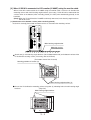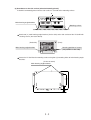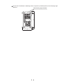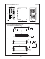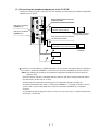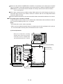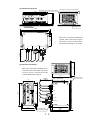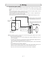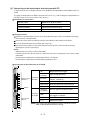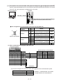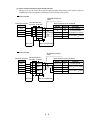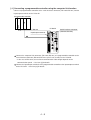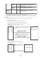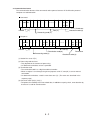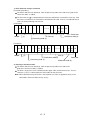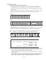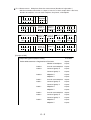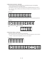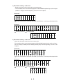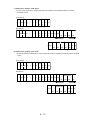
1
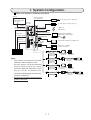
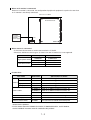
Version 1.0
Produced in Jan. 2004
Instruction Manual
Image sensor camera
Controller
IV-S51M
Thank you for purchasing the SHARP IV-S51M image
sensor camera. The specifications and other details
of IV-S51M are explained in this user's manual. Read
this introductory user's manual carefully to thoroughly
familiarize yourself with the functions and proper
procedures for operation.
Although IV-S51M is designed to create an objective measurement program by simply selecting
and setting necessary parameters in accordance with the instruction given on the screen. In
addition to this manual, a supplementary manual is provided to explain functions and settings.
Ask our sales department (refer overleaf) for this supplementary manual.
Notes
• This manual was written with the utmost care. However, if you have any question or
inquiries concerning the product, please feel free to contact our dealers or service agents.
• Copying all or part of this booklet is prohibited.
• The contents of this manual may be revised or modified for improvement without prior
notice.
TOP - 1
Components of IV-S51M
The components of IV-S51M are as follows.
Accessories
One(1) Controller IV-S51M
• Two (2) Main housing angle brackets (for the
bottom/backside)
• Two (2) Main housing angle brackets (for the side)
• Four (4) Securing screws
• Two (2) D sub-connector (9-pin, D-sub, male, M2.6
lock screw for serial interface of IV-S51M)
• One (1) 17-pin terminal connector
• One (1) 23-pin terminal connector
• One (1) Instruction manual
Components - 1
Safety Precautions
Read this user's manual and the attached documents carefully before installing, operating, or performing any
maintenance, in order to keep the machine working correctly. Make sure you understand all of the equipment
details, safety information, and cautions before using this machine. In this user's manual, the safety
precautions are divided into "Dangers" and "Cautions" as follows.
Danger
: Improper handling is likely to lead to death or serious injury.
Caution
: Improper handling may lead to injury or damage to equipment.
Caution is given, serious results may occur depending on the
Even when only a
circumstances. In all cases, important points are described. Be sure to follow the
advice given.
The following symbols are used to prohibit or explain required action.
: This means do not do what is described. For example, prohibited disassembly is shown as
: This means an action you must take. For example, a ground connection that must be made is
.
shown as
(1) Installation
Caution
• Use only in the environments specified in the catalog, instruction manual, or user's manual.
Electric shock, fire or malfunction may result if used in high temperature, high humidity,
dusty or corrosive environments, or if excessive vibration or impact occurs.
• Install the equipment only as described in the manual.
An improper installation may cause the equipment to fail, breakdown, or malfunction.
• Never leave wire cuttings or any other foreign matter lying about.
A fire, breakdown or malfunction may result from inappropriate objects left near the equipment.
(2) Wiring
Caution
• Connect only to the specified power source.
Connection to the wrong power source may cause a fire.
• Wiring should be performed by a qualified electrician.
Improper wiring may lead to a fire, machine failure or electric shock.
(3) Use
Danger
• Do not touch the terminals while the power is turned ON or you may receive an electric shock.
• Assemble an external emergency stop circuit and interlock circuit (external to the IV-S51M
compact image sensor camera). Otherwise a breakdown or damage to the other equipment
may occur due to a problem with the IV-S51M.
Caution
• Take special care to follow all safety guidelines if you are changing the parameters for the
operating conditions or performing an "enforced output," "run," or "stop" during operation.
Misoperation may damage the machine or cause an accident.
• Turn ON the power supplies in the specified sequence. Turning ON the supplies in the wrong
order may lead to a machine breakdown or cause an accident.
Sefety - 1
.
(4) Maintenance
Warning
• The IV-S51M controller contains a lithium battery. Do not expose the IV-S51M
directly to flames as the battery may explode and seriously injure people nearby.
Prohibit
• Do not disassemble or modify the camera.
Fires, breakdowns or malfunctions may occur, if the camera is disassembled.
Caution
• Turn OFF the power source before connecting or disconnecting the IV-S51M.
If you don't, electric shocks, malfunctions or breakdown may occur.
Sefety - 2
1. System Configuration
When an IV monitor is not directly connected
100V AC
Extension terminal
RS-232C/RS-422
AC-DC Converter
commercially available
power supply
Power supply module for lighting, etc.
IV-S51M
Controller
For future extension (USB storage, etc.)
24V DC
General-purpose serial
I/F (RS-232C/RS-422)
(Accessory for the IV-S51M)
Parallel output
(16 output terminals)
USB terminal
USB mouse,
USB trackball
USB terminal
100BASE-TX/10BASE-T
Supporting tool IV-S50SPM
Optical system selection expert
Analog RGB output
Parallel input
(16 input terminals)
Commercially available analog RGB monitor
Monitor cable
IV-S50MC2
LCD monitor for IV-08MP
(built-in touch panel)
Programmable controller
(Note)
• Only connect or disconnect the camera
connectors while the power is OFF.
• Push the convex side of the connector
into the concave side of the mating
connector. When the connector is all the
way on, it clicks. To disconnect the
connector, hold the plug of the connector,
and pull it straight out.
• You must have a camera connected to the
camera1 connector.
Camera cable
IV-S30KC3(3m)
IV-S30KC5(5m)
IV-S30KC7(7m)
Camera cable
IV-S30KC3(3m)
IV-S30KC5(5m)
IV-S30KC7(7m)
Camera cable
IV-S30KC3(3m)
IV-S30KC5(5m)
Camera cable
IV-S30KC3(3m)
IV-S30KC5(5m)
1-1
Standard camera
(IV-S30C1)
Standard lens
(IV-S20L16)
Micro camera
(IV-S30C2)
High-speed camera
(IV-S30C3)
ø17 lens
(off-the-shelf product)
Standard lens
(IV-S20L16)
Micro, high-speed camera
ø17 lens
(IV-S30C4)
(off-the-shelf product)
When an IV monitor is connected
When an IV monitor is connected, the configuration of peripheral equipment is equal to the one when
an IV monitor is not directly connected.
LCD monitor for IV-08MP
IV-S51M Controller
AC-DC
Converter
commercially
available
power supply
24V DC
When camera is connected
• A maximum of two cameras can be connected to the IV-S51M.
• Mixed use of different camera types (IV-S30C1/C2 and IV-S30C3/C4) is not supported.
Camera mode
Camera port
Connectable camera
High-speed camera
CAMERA1
CAMERA2
IV-S30C3/C4
IV-S30C3/C4
IV-S30C1/C2
IV-S30C1/C2
Standard camera
CAMERA1
CAMERA2
Product lines
Item name
Camera
Model name
Specification or details
Standard
IV-S30C1
Camera main housing (without lens or camera cable)
Micro
IV-S30C2
Camera main housing (without lens or camera cable)
High-speed
IV-S30C3
Camera main housing (without lens or camera cable)
Micro, high-speed camera IV-S30C4
Camera main housing (without lens or camera cable)
IV-S30KC3
Cable for IV-S30C1/C2/C3/C4 camera, 3m
IV-S30KC5
Cable for IV-S30C1/C2/C3/C4 camera, 5m
IV-S30KC7
Cable for IV-S30C1/C2 camera, 7m
Camera lens
IV-S20L16
C mount lens with a 16mm focal length
Parameter setting support software
IV-S50SPM Runs on Windows2000/XP
Exclusive LCD monitor
IV-08MP
Camera cable
TFT LCD 8.4-inch monitor with touch panel
• For the details about the IV-S50SPM and IV-08MP, see the individual instruction manuals
attached to the products.
• For the details about the IV-S30C1/C2/C3/C4, IV-S30KC3/KC5/KC7, and IV-S20L16,
see the individual instruction manuals attached to the products.
1-2
2. Part Names and Functions
This section describes the names and functions of the IV-S51M Controller.
(Front)
Power lamp
Power terminal block
IV-S51M
POWER
FG
+24V
USB
+ 0V
Serial interface connector
Terminator
(termination resistance) lamp
Extension connector
Output terminal block
Input terminal block
Y0
Y1
Y2
Y3
Y4
Y5
Y6
Y7
Y8
Y9
Y10
Y11
Y12
Y13
Y14
Y15
RDY
HALT
COM
USB connector
USB
TERMINATOR
LINK
EXP
LAN interface connector
LAN
RX
ANALOG
RGB
C (-)
CAMERA1
X0
X1
X2
X3
X4
X5
X6
X7
X8
X9
X10
X11
X12
X13
X14
X15
IV MONITOR
ONLY
Analog RGB monitor
connector
Camera 1 connector
CAMERA2
IV monitor connector
C (+)
Camera 2 connector
(Top)
Mounting hole for angle bracket
(for mounting on side)
(Side)
Mounting hole for angle bracket
(for mounting on backside)
(Backside)
Connector cover
(Bottom)
Mounting hole for angle bracket
(for mounting on bottom)
Mounting hole for angle bracket
(for mounting on backside)
Mounting hole for angle bracket
(for mounting on side/bottom)
2-1
Name
Input terminal block
(INPUT: X0 to X15)
Output
terminal
block
Function
This block has 16 input terminals.
• External devices are connected to these terminals for input
(parallel I/F).
OUTPUT : Y0 to Y15
This block has 16 output terminals.
• External devices are connected to these terminals for output
(parallel I/F).
RDY(READY)
This will turn ON when the measurement start input is enabled.
HALT
This turns OFF when the image processing is halted.
This turns ON when image processing is running.
Power terminal block (+24V, 0V)
Commercially available constant-voltage power supply
(24V DC ±10%, 2A or more) is connected here.
Serial interface connector
(RS-232C/RS-422)
This connector is used to connect a personal computer for
communications (general-purpose serial I/F) or to connect
programmable controller for a computer link.
Extension connector
(RS-232C/RS-422)
This connector is used to connect external devices (power
supply module for lighting, etc.) for communications (generalpurpose serial I/F).
Terminator
(termination resistance) lamp
When terminating resistance at RS-422 input of generalpurpose serial port (COM) is ON, this lamp will be lit. When IVS51M is connected to several peripheral devices at RS-422,
turn ON the terminating resistance of IV-S51M or the peripheral
devices which are located at the both ends of the cable.
ON/OFF will be set for the termination resistance of IV-S51M in
"Setting up system parameters".
Power lamp (POWER)
When power is supplied to the IV-S51M, this lamp will light
green.
USB connector (×2)
USB mouse or USB trackball are connected here. Use the
devices with 100mA or less. The upper connector is for future
extension to be used for USB storage or other purposes.
LAN interface connector
(10 BASE-T/100 BASE-TX)
Ethernet cable is used when IV-S51M is connected to LAN
(runs on 10 BASE-T/100 BASE - TX)
Analog RGB monitor connector
(ANALOG RGB)
Commercially available analog RGB monitor with SVGA display
function is connected here.
Connector for IV monitor
(IV MONITOR ONLY)
Monitor cable (IV-S50MC2:to be sold separately) is connected
to here when the LCD monitor (IV-08MP) is separately used.
This will be not used when a monitor and IV-S51M are directly
connected.
Camera 1 connector (CAMERA 1)
Camera 2 connector (CAMERA 2)
The camera cable connector is connected here.
• The camera connected to the CAMERA 1 position is camera 1,
and the camera connected to the CAMERA 2 position is camera 2.
Mounting hole for angle bracket
This is the hole to mount angle bracket to IV-S51M. There are
two types of angle brackets which are the angle bracket for the
side mount and the angle bracket for backside/bottom mount
(common).
Connector cover
This cover is removed, when IV-S51M and LCD monitor
(IV-08MP) are directly connected.
2-2
3. Connection and Installation Method
This section describes how to connect IV-S51M and LCD monitor. IV-S51M and LCD monitor can be
directly connected or connected using the monitor cable.
[ 1 ] When IV-S51M is directly connected to LCD monitor (IV-08MP)
When IV-08MP is directly connected, follow the instructions below to connect the monitor to
IV-S51M.
(Note) When IV-08MP and IV-S51M are not directly connected and used separately, the work
explained here are not be required.
Remove the connector cover from the main housing of IV-S51M.
Connector cover
Fit the tab A of the IV-08MP in the notch part of the IV-S51M.
Tab A
To connect them, press the IV-S51M in place in the direction of the arrow so that the tab B is fit into
the notch part. Make sure that the connectors of both units are firmly connected.
Tab B
IInsert two (2) main housing angle brackets (supplied with IV-08MP) as indicated below and fix
them with two (2) securing screws (supplied with IV-08MP).
Securing screws
3-1
[ 2 ] When IV-S51M is connected to LCD monitor (IV-08MP) using the monitor cable
When IV-S51M is connected to the IV-08MP using the monitor cable, secure the IV-S51M to the
mounting surface with main housing angle brackets (accessory). IV-S51M can be mounted on the
surface either at the bottom (when vertically placed), the side (when horizontally placed), or the
backside.
(Note) When the IV-S51M and the IV-08MP are directly connected, main housing angle brackets
will not be used.
(1) Attachment at the bottom surface (when vertically placed)
IV-S51M is vertically placed and its bottom surface is secured to the mounting surface.
IV-S51M
POWER
FG
+24V
USB
+0V
Y0
COM
Y1
Y2
Y3
USB
Y4
Y5
TERMINATOR
Y6
LINK
Y7
Y8
Y9
Y10
Y11
LAN
EXP
Y12
RX
Y13
ANALOG
RGB
Y14
Y15
RDY
HALT
C (-)
X0
CAMERA1
X1
X2
X3
X4
IV MONITOR
ONLY
X5
X6
CAMERA2
X7
Main housing angle bracket
X8
X9
X10
X11
X12
X13
X14
Mounting surface
X15
C (+)
Attach two (2) main housing angle brackets (for the bottom/backside) to the bottom surface of the
IV-S51M with securing screws (accessory, two each: M3×8)
(The bottom view of the IV-S51M)
Securing positions of screws (4)
Main housing angle brackets (2)
93
23.2
80
3-2
105
Secure the IV-S51M to the mounting surface using four (4) mounting holes of main housing angle
brackets.
(Top view)
Main housing angle brackets
(2) Attachment at the side surface (when horizontally placed)
IV-S51M is horizontally placed and its side surface is secured to the mounting surface.
IV MONITOR
ONLY
ANALOG
RGB
X15
X14
X13
Mounting surface
C (+)
X12
X10
X11
X9
CAMERA2
X8
X7
X5
X4
CAMERA1
X2
X3
X1
X0
C (-)
HALT
RDY
Y14
Y15
Y13
Y12
EXP
Y11
Y10
Y9
Y7
Y8
Y6
Y5
Y4
Y3
Y2
Y0
Y1
+0V
FG
+24V
COM
Main housing angle brackets
X6
RX
LAN
USB
TERMINATOR
IV-S51M
USB
LINK
POWER
A
Attach two (2) main housing angle brackets (for the side) to the side surface of the IV-S51M with
securing screws (two each: M3×8).
(Backside)
(Front)
Securing positions of screws
(two positions at one side)
Main housing angle brackets
Secure the IV-S51M to the mounting surface using four (4) mounting holes of main housing angle
brackets.
(A view on arrow)
80
198.4
3-3
6.0
126.4
Main housing angle brackets
(3) Attachment at the backside surface
The backside surface of IV-S51M is secured to the mounting surface.
Main housing angle brackets
A
Mounting surface
Attach two (2) main housing angle brackets (for the bottom/backside) to the backside surface of
the IV-S51M with securing screws (two each: M3×8)
(A arrow diagram)
Main housing angle brackets
Securing positions of screws
(4)
CONTROLLER
IV-S51M
3-4
16.2
CONTROLLER
IV-S51M
144
16.2
Secure the IV-S51M to the mounting surface using four (4) mounting holes of main housing angle
brackets.
Main housing angle brackets
93
3-5
External dimension of the IV-S51M
(Unit: mm)
81
IV-S51M
POWER
FG
+24V
USB
+0V
Y0
COM
Y1
Y2
Y3
USB
Y4
Y5
TERMINATOR
Y6
LINK
Y7
Y8
Y9
Y10
Y11
EXP
LAN
Y12
176.4
ANALOG
RGB
Y14
Y15
CONTROLLER
IV-S51M
RDY
HALT
C (-)
X0
176.4
RX
Y13
CAMERA1
X1
X2
X3
X4
IV MONITOR
ONLY
X5
X6
CAMERA2
X7
X8
X9
X10
X11
X12
X13
X14
X15
C (+)
81
126.4
136.4
External dimension of main housing angle bracket
• For the attachment to the bottom/backside
(Unit: mm)
2-ø3.5
93
15
2-ø4.5
55
105
80
2
8
75
• For the attachment to the side
10
11.95
6
17.7
2-ø4.5
2
80
5
26
15
15
2-ø3.5
95
3-6
[ 3 ] Connecting the peripheral equipment to the IV-S51M
Connect the camera (up to 2 cameras), the LCD monitor, and commercially available analog RGB
monitor to the IV-S51M.
IV-S51M
POWER
FG
+24V
USB
+0V
Y0
COM
Analog RGB monitor connector
(ANALOG RGB)
Y1
Y2
Y3
USB
Y4
Y5
TERMINATOR
Y6
Camera 1 connector
(CAMERA 1)
LINK
Y7
Y8
Y9
Y10
Y11
EXP
LAN
Y12
RX
Y13
ANALOG
RGB
Y14
Y15
RDY
HALT
Camera 2 connector
(CAMERA 2)
C (-)
Analog RGB monitor cable
(off-the-shelf product)
CAMERA1
Commercially available
analog RGB monitor
X0
X1
X2
X3
X4
IV MONITOR
ONLY
X5
X6
X7
X8
X9
X10
X11
X12
CAMERA2
Connector for exclusive monitor
(IV MONITOR ONLY)
X13
X14
X15
C (+)
IV monitor cable
(IV-S50MC2: to be sold separately)
LCD monitor
(IV-08MP)
Camera 1
Camera 2
Connect the camera cable (IV-S30KC3/KC5/KC7) or the camera conversion cable (IV-S30HC) to
the camera 1 connector (CAMERA 1) and camera 2 connector (CAMERA 2) on the IV-S51M.
(Note) Only connect or disconnect the peripheral equipment including the camera while the
power is OFF.
• Push the convex side of the connector into the concave side of the mating connector. When
the connector is all the way on, it clicks.
• To disconnect the connector, hold the plug of the connector and pull it straight out.
• A camera connected to the camera 1 connector (CAMERA 1), is treated as camera 1 by this
system, and a camera connected to the camera 2 connector (CAMERA 2) is treated as
camera 2.
• It is possible to connect only one camera. In this case, you must have a camera connected to
the camera 1 connector.
3-7
When the LCD monitor IV-08MPand the controller are separately used, connect the IV monitor
cable (IV-S50MC2: to be sold separately) to the connector for IV monitor (IV MONITOR ONLY).
(Note) When the LCD monitor and the controller are directly connected, the work described
here is not required.
When other commercially available analog RGB monitor with SVGA display function are
connected other than the LCD monitor, connect the monitor cable to the analog RGB monitor
connector (ANALOG RGB).
See the individual manual for each camera for details about connection/installation of the camera.
Leave enough space around the IV-S51M
In order to connect camera cables, the IV monitor cable, RGB monitor cable and Ethernet cable to
the IV-S51M, the following space (min.) is required.
(Note)
• Do not bend the camera cables repeatedly.
• Make sure the installation location allows the enough space for the input/output wires going to
the I/O terminal block and the power terminal block on the IV-S51M.
93
* When the IV-S51M is vertically
placed, make sure that the space
of at least 10 mm is secured at the
top and the backside of IV-S51M.
23.2
81
80
100mm
(minimun)
105
(1) Vertical placement
23.2
Provide the space by more than 10 mm.
Provide the space
by more than 10 mm.
USB
183.7
176.4
LAN
RGB
CAMERA
7.3
IV MONITOR
105
10
Mounting surface
3-8
126.4
136.4
(2) Horizontal placement
Provide the space by more than 10 mm. Provide the space by more than 10 mm.
8
81
89
176.4
Mounting surface
Mounting surface
210.4
23.2
198.4
80
* When the IV-S51M is horizontally
placed, make sure that the space
of at least 10 mm is secured at the
top and the backside of IV-S51M.
CAMERA
LAN
RGB
IV MONITOR
100mm
(minimun)
USB
105
(3) Backside attachment
* When the IV-S51M is mounted at the
backside, make sure that the space of
at least 10 mm is secured at the top
and the bottom of IV-S51M.
133.7
100mm
(minimun)
16.2
81
Mounting surface
Provide the space
by more than 10 mm.
USB
144
176.4
LAN
RGB
CAMERA
16.2
IV MONITOR
93
105
Provide the space
by more than 10 mm.
3-9
10
126.4
136.4
7.3
4. Wiring
[ 1 ] Connecting a power supply
Connecting a commercially available constant-voltage power supply to the power terminal
(POWER: +24V, 0 V) on the IV-S51M. Use a 24 VDC±10%, 2A or more constant-voltage power
supply.
• Use an individual power supply to supply power to the IV-S51M. If the power supply is used to
power other equipment, measurement error may occur.
• Check the polarity of the power supply terminals, +24 V and 0 V. If power is supplied with the
polarity inverted, the IV-S51M may be damaged.
• Only connect or disconnect the camera cable and other equipment while the power is OFF.
This distance must be as short as possible
(Recommended distance: less than 1 m)
Frame ground
terminal
TG terminal Power supply terminal (+24V)
(-)
24V DC
(+)
Fuse
(2.5 A)
Power supply terminal
(0 V)
Constant-voltage
power supply
(Note) To improve the noise resistance of the constant-voltage power supply to the IV-S51M,
observe the following precautions.
• Ground the FG terminal of the constant-voltage power supply according to the class D
(class 3) grounding.
• The power line between the IV-S51M and the constant-voltage power supply must be as
short as possible. (Recommended distance: less than 1 m)
Do not run the power supply line near any noise generating sources, such as electric motor
lines.
• Use twisted-pair wire for the power supply line.
• Connect the power/output terminal block and the input terminal block while they are
detached. If they are connected while they are attached, damage may occur.
• Only insert each terminal into the controller after all the wiring is completed.
4-1
[ 2 ] Connecting to the input/output terminals (parallel I/F)
16 input terminals and 16 output terminals are available on the input/output terminal block on the IVS51M.
The input terminal block has INPUT terminals X0 to X15, C(+), and the output terminal block has
OUTPUT terminals Y0 to Y15, RDY, HALT and C(-).
Conditions for connection
Size of the wire
AWG22 to 16 (0.33 to 1.65m3)
Type of the wire
Single wire, twisted wire
Terminal treatment
Peel off the wire cover by 7mm
Screw torque
0.25Nm
Wiring procedure
Remove the terminal block from the IV-S51M by loosening two screws at the both end (flange),
whichsecure the terminal block.
Loosen the screw of the terminal by turning it anti-clockwise with slotted screw driver.
Insert the peeled wire into the terminal and screw it up.
After all the wiring is done, fit the terminal block in place on the IV-S51M, and secure it by
tightening the screws at the flange.
(Note)
• Soldered wire may cause a loose connection.
• Connect only one wire to one terminal. If more than one wire is connected, it may cause a loose
connection.
• Do not plug in or unplug the terminal block while it is energized.
• Do not plug in or unplug the terminal block by pulling the wire.
Input/output terminal block on the IV-S51M
FG
+24V
+0V
YO
Y0
Y1
Y1
Y2
Y2
Y3
Y3
Y4
Y5
Y6
Y7
Y7
Y8
Y8
Y9
Y9
Y10
Y12
Y13
Y15
RDY
C (-)
X0
HALT
COM
X1
X4
X7
X8
X9
X10
X9
X11
X12
X13
X14
X15
Execution for individual camera
(camera 1/camera 2)
X9
Standard image registration
X10 to X15
General-purpose input for micro PLC
C(+)
Common for input
Y0 to Y15
(15 points)
Result of logical calculation output
RDY
This will turn ON when the measurement
start trigger is enabled.
Input terminal
(INPUT)
RUN
This will turn OFF when a problem occurs.
C (-)
Common for output
X10
X11
X12
X7 to X8
X5
X6
X7
X8
Terminals
for output
X3
X5
X6
READY
X2
X3
X4
Type change (64 types)
X0
X1
X2
X1 to X6
(7 points)
Y14
Y15
HALT
Terminals
for input
Y11
Y13
Y14
Output terminal
(OUTPUT)
Y10
Y11
Y12
Measurement start trigger
Y4
Y5
Y6
X0
X13
X14
(Note) Only connect the terminal block while the connector terminal
block is detached from the main housing.
X15
C (+)
COM
4-2
I/O port
The input/output terminals are isolated by photocouplers, to prevent malfunctions caused by
noise. Use them within the rated range. The specifications of the input/output ports are listed
below.
Item
Input
Rating
Rated input voltage
12/24V DC
Input voltage range
10.8V to 26.4V DC
Input voltage level
ON: 10.5V or less, OFF: 5V or more
Input current level
ON: 3mA or less, OFF: 1.5mA or more
Input impedance
3.3KW
Response time
1 ms or less (OFF to ON, ON to OFF)
Rated output voltage
12/24V DC
Load voltage range
10.8V to 26.4V DC
80mA DC
Rated max. output current
Output Output type
Photocoupler open connector
ON voltage drop
1.2V or less (80mA)
Isolation method
Response time
Photocoupler isolation
1 ms or less (OFF to ON, ON to OFF)
Wiring to the IV-S51M
Input
Output
L
+
Fuse
(*)
C (+) Y0...Y15
L
RDY
L
RUN
Power supply
X15
Load
Power supply
X0
-
+
-
Fuse
(*)
C (-)
FG
Protective element
(Power supply limit: 33V)
IV-S51M
*Use the capacity appropriate to the load.
4-3
[ 3 ] Connection for communication with personal computer (general-purpose serial I/F)
Connect a personal computer to the serial interface connector (RS-232C/RS-422) on the IV-S51M.
A 9-pin D-sub, male connector is included with the IV-S51M.
IV-S51M
Personal computer
IV-S51M
POWER
FG
+24V
USB
+0V
COM
Y0
Y1
Y2
Y3
USB
Y4
Y5
RS-232C / RS-422
TERMINATOR
Y6
LINK
Y7
Y8
Y9
Y10
LAN
EXP
Y11
Y12
RX
Y13
ANALOG
RGB
Y14
Y15
RDY
HALT
C (-)
CAMERA1
X0
X1
X2
X3
X4
IV MONITOR
ONLY
X5
CAMERA2
X6
Serial interface connector (RS-232C/RS-422
9-pin D-sub female, M2.6 lock screw)
X7
X8
X9
X10
X11
X12
X13
X14
X15
C (+)
Pin arrangement of serial interface connector (RS-232C/RS-422)
Communication Pin Signal
standard
No. name
9
5
6
1
RS-232C
(9-pin D-sub female)
RS-422
Details
Direction
2
RD
Received data
(personal computer IV-S51M)
input
3
SD
Transmitted data
(IV-S51M personal computer)
output
5
4
7
8
9
SG
TA
TB
RA
RB
FG
Connector case
Signal ground
Transmitted data
(IV-S51M personal computer)
output
Received data
(personal computer IV-S51M)
Frame ground
input
(1) When communicating through the RS-232C port
Personal computer
DOS/V, IBM-PC
PC98 series
9-pin D-sub 25-pin D-sub
Pin No.
Pin No. Signal name
Connector case Connector case
FG
3
2
SD
2
3
RD
5
7
SG
7
4
RS
8
5
CS
6
6
DSR
1
8
CD
4
20
DTR
Serial interface on the IV-S51M
Pin No. Signal name Function
Frame ground
FG
Connector case
Received data
RD
2
Transmitted data
SD
3
Signal ground
SG
5
*(RS-232C)
* The maximum length of the communication cable depends on the communication speed.
Communication speed
9.6, 19.2
38.4, 57.6, 115.2
Cable length
• Conduct a communication test before
15m or less
using the devices for measurements
2 to 3m
4-4
(2) When communicating through the RS-422 port
Specify the 4-wire or 2-wire on the [Serial Communication Parameters] menu from the [System
Conditions] menu of IV-S51M in accordance with the actual wiring system.
4-wire system
Shielded twisted-pair
cable
RS-232C/RS-422
Personal computer converter Z-101HE
Signal name
1 FG SHIELD
FG
2 TD
RD(+)
TD
3
RD
RD(–)
RD
7 SG
TD(+)
SG
TD(–)
15m or less
Serial interface on the IV-S51M
Function
Pin No. Signal name
Frame ground
FG
Connector case
TA
4
Transmitted data
(IV-S51M
personal computer)
TB
7
RA
8
Received data
(personal
computer IV-S51M)
RB
9
1km or less(RS-485)
(RS-232C)
2-wire system
Shielded twisted-pair
cable
RS-232C/RS-422
Personal computer converter Z-101HE
Signal name
1 FG SHIELD
FG
2 TD
TD
RD(+)
3 RD
RD
4 RS
RS
RD(–)
7 SG
SG
15m or less
Serial interface on the IV-S51M
Pin No. Signal name
Function
Frame ground
FG
Connector case
TA
4
Transmitted data
(IV-S51M personal computer)
TB
7
Received data
RA
8
(personal
computer IV-S51M)
RB
9
1km or less(RS-485)
(RS-232C)
4-5
[ 4 ] Connecting a programmable controller using the computer link function
Connect a programmable controller to the serial interface connector (RS-232C/RS-422) and the
input/output terminals on the IV-S51M.
I/O
Communication
port
Programmable controller
IV-S51M
RS-232C / RS-422
Input/output terminals
IV-S51M
POWER
Serial interface connector
(RS-232C/RS-422)
FG
+24V
USB
+0V
Y0
COM
Y1
Y2
Y3
USB
Y4
Y5
TERMINATOR
Y6
LINK
Y7
Y8
Y9
Y10
Y11
EXP
LAN
Y12
RX
Y13
ANALOG
RGB
Y14
Y15
RDY
HALT
C (-)
X0
CAMERA1
X1
X2
X3
X4
IV MONITOR
ONLY
X5
X6
CAMERA2
X7
X8
X9
X10
X11
X12
X13
X14
X15
C (+)
Connect the computer link connector (RS-232C/RS-422) of a programmable controller to the
serial interface connector (RS-232C/RS-422: 9-pin D-sub, female) on the IV-S51M.
• In the case of RS-232C, the maximum communication cable length depends on the
communication speed. → See item [3] for details.
Connect the input/output terminals of the programmable controller to the input/output terminals
on the IV-S51M. → See item [2] for details.
4-6
[ 5 ] Connecting to the analog RGB monitor connector
Connect an analog RGB monitor and the analog RGB monitor connector on the IV-S51M with a
commercially available RGB monitoar cable.
Commercially available analog RGB monitor
IV−S51M POWER
FG
+24V
USB
+0V
Y0
COM
Y1
Y2
Y3
USB
Y4
Y5
TERMINATOR
Y6
LINK
Y7
Y8
Y9
Y10
Y11
LAN
EXP
Y12
RX
ANALOG
RGB
Y13
Y14
Y15
RDY
HALT
C(−)
CAMERA1
Commercially available monitor cable
X0
X1
X2
X3
X4
IV MONITOR
ONLY
X5
X6
CAMERA2
X7
X8
X9
X10
X11
X12
X13
X14
X15
C(+)
Pin arrangement of RGB monitor connector
Pin No.
1
10
5
15
11
1
6
Signal name
R
2
G
3
B
4
−
5
GND
6
RGND
7
GGND
8
BGND
9
−
10
GND
11
−
12
DDAT
13
H_SYNC
14
V_SYNC
15
DDCK
[ 6 ] Connecting to the extension connector
Pin alignment of the extension is equal to the one of the serial interface connector.
The details of the communication vary from the equipment to be connected.
Termination resistance of RS-422 is always ON.
4-7
5. Specifications
Item
Image sampling system
No. of pixel
Specifications
Monochrome 256 level
Analog camera 512×480
Image memory
No. of assignable object type
Shared with image processing memory
64 object types
No. of camera to be connected Up to 2 cameras
Image processing
Gray, binary conversion
Image capture Standard camera 33.3ms
time
High-speed camera 16.7ms (full mode), 8.3ms (half mode)
Gray search time
8ms (model: 64×64, search area: 256×256, when the speed is prioritized)
Gray search, edge detection precision Sub-pixel
Gray level change Histogram widening
Gray image Noise elimination Smoothing (average/ center)
pre-processing
Edge extraction (primary differentiation, secondary differentiation),
Outline extraction
horizontal edge, vertical edge
Binary threshold value
Binary noise elimination
Positional correction method
Window shape
Fixed and threshold value correction (variation difference/variation rate)
Expansion, contraction, area filter
X/Y correction, rotation correction
Rectangle, circle, oval, polygon, and free shape
5-1
Item
Specifications
Object:
single workpiece,
simultaneously
Output: coordinate
multiple workpieces can be processed
Object:
single workpiece,
simultaneously
Output: coordinate, angle
multiple workpieces can be processed
Shape degree of
match inspection
Object:
multiple workpieces can be processed
Point sensor
Output: yes or no
Existence of work/
size inspection
Measurement:
Output: area
Workpiece
counting
Object: all the workpieces designated workpieces
Output: number of object detected
Position detection
Position &
attitude angle
Inspection
program
single workpiece,
simultaneously
Output: Degree of match
no individual workpiece
individual workpiece
Detecting the number
of projected parts and
the width, interval, etc. The number of projected parts, interval, width (point alignment)
of the alignment
Distance &
angle
measurement
Object:
single workpiece, multiple workpieces can be processed
simultaneously
Output: distance (between 2 points/X coordinate/Y coordinate),
angle (3 points/2 points against vertical line/2 points against
horizontal line)
Workpiece
dimension
measurement
Output: number of workpieces, total area, area for each workpieces,
diameter of the projection width, circumference length, main
axes angle
Image processing
Object: position detection, position & attitude angle, existence of
procedure automatic
work / size inspection, workpiece count inspection, distance &
generating expert
angle measurement, and workpiece dimension measurement
(binary processing)
Number of inspection program
Arithmetic operation
NG image memory function
Maximum 8 inspections/type (inspection item 0 - camera 1,
inspection item 0 - camera 2, and inspection item 1 to 6)
Four basic operations (+, −, ×, / ), root, absolute value, TAN, ATAN,
maximum, minimum, average, and total
Maximum 128 images (8 whole scenes)
Calendar timer
Year, month, day, hour, and minute
Optical system Image adjustment 1
Focus adjustment contrast adjustment
configuration
Image adjustment 2
Image distortion diagnosis & compensation
setting
calibration
Lighting adjustment Adjustment of light volume
Optical system
Monitoring illuminance→shading diagnosis→optical system automatic
maintenance Light level a
utomatic adjustment adjustment ( light volume shutter speed)
Other functions
Micro PLC
Displaying measuring time, monitoring illuminance, crosshair cursor
display, switching language between Japanese and English, Running
screen lock function, and change image display (through/freeze)
Input relays
16 points (X0 to X15)
Output relays
16 points (Y0 to Y15)
Auxiliary relays
Internal auxiliary 1024 points (C0 to C1023), system auxiliary 64 points (S0 to S63)
Timer
16 points (TM0 to TM15), timer setting (0.01 to 9.99 seconds), (down counter)
Counter
16 points (CN0 to CN15), counter setting (1 to 999), (up counter)
5-2
Item
Specifications
Parallel interface
IPU external
interface
Serial interface
Input 16 points (X0 to X15) 12/24V DC 7mA (24V DC)
Output 16 points (Y0 to Y15) 12/24V DC 80mA (open corrector)
RS-232C/RS-422 (2-wire system/4-wire system) (2.4 to 115.2kbps)
upward calculator, PLC
Extension terminal RS-232C/RS-422 (2-wire system only) used for lighting control
Measurement
start input
Internal trigger
CCD trigger
External trigger
Trigger input (parallel interface), serial trigger, and manual trigger
(for testing)
Power supply input
+24V, 0V
FG
Input common 1 point
Interrupt input (trigger) 1 point
Input 15 points
Parallel interface
Output common 1point
READY 1 point
HALT output 1 point (interlocking with watchdog timer)
Output 16 points
Control function
Lighting
control
Dimmer function, lamp ON/OFF (LED), shutter ON/OFF (halogen)
Number of control 4 systems, 2 controls/1 system
Control port
RS-232C/RS-422
Power supply voltage / power
consumption
24V DC (±10%) 30W
Operation ambient
temperature / atmosphere
0 to 45°C / 35 to 95% RH (no condensation)**
Storage ambient temperature /
atmosphere
-20 to 70°C / 35 to 95% RH (no condensation)
Outside dimension/weight
USB host
HMI External
interface
LAN
Image output
Operation input
Image output
Cameras to be connected
81mm (W) × 176.4mm (H) × 126.4mm (D)
(protruding portions are not included)
USB 1.1 specification, 2 channel (power supply capacity 100mA / ch)
10/100 base-TX
VGA output port 1 point, IV LCD monitor output 1 point
Touch panel, and commercially available USB mouse (*)
SVGA (800 × 600 × 24bpp) analog output
IV LCD monitor (800 × 600 × 18bpp) digital output
IV-S30C1, IV-S30C2, IV-S30C3, and IV-S30C4
* Both can be used at the same time, but touch panel overrides the USB mouse.
**When this is used with the IV-08MP LCD monitor as one unit, temperature should be 0 to 40°C.
5-3
Communication (General Purpose Serial Interface)
The IV-S51M can communicate with a personal computer that transmits commands and receives
responses to process measurement execution commands.
List of processing function
1. Outline
• The following functions and commands are supported by IV-S51M.
Functions
Communication
port
Measurement
execution
Executes measurement programs for specified
object types and outputs the numeric value results.
COM
Result data
reading
• Outputs the numeric value result of the last
measurement (measurement is not executed).
COM
Lighting
control
• Monitoring illuminance
• Light level automatic adjustment
COM
Item
Control lighting power source
• Setting up lighting control system
• Lighting ON / OFF
• Reading / writing light volume
• Reading / writing EEPROM light volume
Self-diagnosis
I/O Link
Diagnosing hardware of image processing board
COM
2. List of commands
Category
Item
Code
Executing
measurement
Measurement
execution 1
0010
• Outputs the numeric value result of the
executed measurement.
• Maximum 512 bytes
Measurement
execution 2
0011
• Outputs the numeric value result of the
executed measurement.
• If the volume of the data exceeds 512 bytes,
it will be divided into packets.
Measurement
execution 3
0012
• Outputs the numeric value result of the last
measurement.
• If the volume of the data exceeds 512 bytes,
it will be divided into packets.
Measurement
data reading 1
0110
• Outputs the numeric value result of the last
measurement.
• Maximum 512 bytes
Measurement
data reading 2
0111
• Outputs the numeric value result of the last
measurement.
• If the volume of the data exceeds 512 bytes,
it will be divided into packets.
Measurement
data reading 3
0112
• Outputs the arithmetic result (double precision
floating decimal point) of the last measurement.
• If the volume of the data exceeds 512 bytes,
it will be divided into packets.
Illuminance
monitor
0118
Executes illuminance monitor to provide the
measured light level and the evaluation result.
Reading
measurement
data
Controlling
lighting
Functions
6-1
(COM * 1)
Illuminance
reading
0119
Reads the amount of illuminance measured by
the illuminance monitor function and the
evaluation result.
Light level
automatic
adjustment
011A
When the illuminance monitor is NG,
adjust the light volume and the shutter speed.
02XX
Checks for abnormalities of hardware at
the image board.
Controlling
lighting
(I/O link * 2)
self-diagnosing
0300
*1: The functions are described in "Optical system control function".
*2: Command specification and other details are described in "Optical system control function".
3. Data flow
The data flow between the IV-S51M and a personal computer is shown below.
1) Measurement execution
See "1. Outline 3. General Purpose Serial Data Flow".
2) Processing other than measurement execution processing
Reading the result data by dividing into packets
[IV-S51M]
Executing result
Receiving a command (packet = 0)
[Personal computer]
Transmitting a response
(packet = 0, 512 bytes)
Receiving a command (packet = 1)
Transmitting a response
(packet = 1, 512 bytes)
:
:
Processing other than the above processing
[IV-S51M]
Operating
Receiving a command
[Personal computer]
Transmitting a response
6-2
4. Communication format
The communication formats of the commands and responses between IV-S51M and a personal
computer are outlined below.
Command
: Station No. *
*
*
*
*
•••••••
*
*
SC SC CR
(H ) (L )
Header
(1)
Terminator
Checksum code (4)
Text (2)
Processing code (2)
Response
: Station No. *
*
*
*
RC RC RC RC
H
Header
•••
•••
*
••••••
*
(L )
(1)
*
SC SC CR
(H ) (L )
Text (2)
Termination code(3)
Processing code (2)
Terminator
Checksum code (4)
(1) Station No.: 00 to 7F(H)
(2) Processing code and text
• They depend on the contents of processing
• On abnormal termination, no text is provided.
(3) Termination code
• The termination code is a 4-digit hexadecimal number.
• When an output is sent through the general purpose serial I/F, 0000(H) is sent on normal
termination.
• On abnormal termination, a code is more than 0001 (H). (The errors are described in the
separate page.)
(4) Checksum code (SC(H), SC(L))
• To improve the reliability of the transmitted data, in addition to a parity check, error detection by
checksum is used for error detection.
6-3
1) Error detection using a checksum
[Detection procedure]
The ASCII code for each data byte, from the processing code to the end of text (prior to the
checksum code), is added.
The final value of " " is compared to the checksum code which is treated the same way. If the
two values are identical, the command is considered to be valid. If not, it is considered that an
error has occurred during transmission.
[Command]
:
Station No.
*
*
*
*
*
•••••••
*
*
SC SC CR
(H ) (L )
Header
(1)
Terminator
Checksum code (4)
Text (2)
Processing code (2)
[Response]
: Station No. *
*
*
*
RC RC RC RC
H
Header
•••
•••
*
••••••
*
(L )
(1)
*
SC SC CR
(H ) (L )
Text (2)
Termination code(3)
Processing code (2)
Terminator
Checksum code (4)
2) Creating a checksum code
The ASCII code for each data byte, from the processing code to the end of text
(prior to the checksum code), is added.
The lower 1 byte of this sum is divided into the upper 4 bits and the lower 4 bits. The hex
character (0 to F) is converted to the ASCII code for that character.
Note: When detection using checksum is not required at IV side, set @(ASCII:40(H)) in the
command's checksum code (SC(H), SC(L)).
6-4
5. Public command format
1) Measurement execution function: code 0010H
• This command will cause the IV-S51M to execute all of the measurement program for a
specified object type or the corresponding measurement program for a specified camera.
• 512 bytes of the result data (from the beginning) of the measurement program will be sent back
as the response.
• In the case of "Measurement start input = CCD trigger or parallel input, serial output = general
purpose serial", result will be sent back to the host as a response of this command.
[Command]
Execution
:
Station No. 0
0
1
0 Object type camera SC SC CR
(H ) (L ) No. (H ) (L )
[Response]
Execution
:
Station No. 0
0
1
0
RC RC RC RC Object type camera Numeric value result SC SC CR
(H ) • • • • • • (L ) (H ) (L ) No.
data
(H ) (L )
• Object type: Object Type to measure (maximum 0 ~ FF(tentatively))
• Execution camera No.: 0 = executing all the cameras, 1 = Camera 1 only, 2 = Camera 2 only
• Numeric value result data (see (4) Output data chart for the details of the output data)
Ex. 1 Measurement 1: Position detection measurement (single workpiece, Number of
registration 2), Measurement 2: Size inspection (no individual workpiece)
Coordinate X
Coordinate Y
Coordinate X
Coordinate Y
(Registration 0) (Registration 0) (Registration 1) (Registration 1)
Total area
(Registration 0)
[Example of HMI]
[Output data (general purpose serial)]
Packet 0
Measurement 1
Measurement 2
F C1 BRT
Registration 0 Coordinate X
2 bytes
Coordinate Y
2 bytes
Registration 1 Coordinate X
2 bytes
Coordinate Y
2 bytes
Registration 0 Total area
4 bytes
Note:Preset the maximum number of detection for the measurement where the amount of output
data is variable until the measurement is executed, and when the actual detection is less
than the maximum number of detection, output a dummy data.
When the actual detection is more than the maximum number of detection, exceeded data
will not be output.
Measurement is executed on: Position detection (multiple/circle center), Position and attitude
angle (multiple), Shape degree of match inspection, Size inspection (individual workpiece),
Distance angle measurement (multiple), and Workpiece dimension measurement
6-5
Ex. 2 Measurement 1 Workpiece dimension measurement (Number of registration 1)
• Maximum number of detection 3 = output as much as 2 labels, output data = total area,
Number of workpiece, area for each workpiece, barycenter, and midpoint
Total area
(Registration
0)
Number of
workpiece
(Registration 0)
Area for each workpiece
Center of
gravity X
Center of
gravity Y
Midpoint X
Midpoint Y
Registration 0
Registration 0
Registration 0
Registration 0
Registration 0
Label 0
Label 0
Label 0
Label 0
Label 0
Area for each workpiece
Center of
gravity X
Center of
gravity Y
Midpoint X
Midpoint Y
Registration 0
Registration 0
Registration 0
Registration 0
Registration 0
Label 1
Label 1
Label 1
Label 1
Label 1
Area for each workpiece
Center of
gravity X
Center of
gravity Y
Midpoint X
Midpoint Y
Registration 0
Registration 0
Registration 0
Registration 0
Registration 0
Label 2
Label 2
Label 2
Label 2
Label 2
[Example of HMI]
[Output data (general purpose serial)]
F C1 BRT
Packet 0 Measurement 1 Registration 0 Total area
4 bytes
Number of workpiece
2 bytes
Label 0
Area for each workpiece
2 bytes
Label 0
Center of gravity X
2 bytes
Center of gravity Y
2 bytes
Midpoint X
2 bytes
Midpoint Y
2 bytes
Label 1
Area for each workpiece
4 bytes
Label 1
Center of gravity X
2 bytes
Center of gravity Y
2 bytes
Midpoint X
2 bytes
Midpoint Y
2 bytes
Label 2
Area for each workpiece
4 bytes
Label 2
Center of gravity X
2 bytes
Center of gravity Y
2 bytes
Midpoint X
2 bytes
Midpoint Y
2 bytes
Label 0
Label 1
Label 2
6-6
Ex. 3 Measurement 1 Point sensor
• 8 points are handled by 1 byte.
• Black & white = FA(H)
F
Point No.
A
1
1
1
1
1
0
1
0
P7
P6
P5
P4
P3
P2
P1
P0
Black & white White White White White White Black White Black
0 = Black, 1 = White
[Example of HMI]
[Output data (general purpose serial)]
Packet 0 Measurement 1
F C1 BRT
Registration 0 ~7
1 bytes
Registration 8 ~ 15
1 bytes
2) Measurement execution 2: code 0011H
• Execute all of the measurement programs for a specified object type or corresponding
measurement program for the specified camera.
• The result data of the measurement program will be divided into packets by each 512 bytes
(128 data × 4 bytes) from the beginning, and sent as the response.
[Command]
Execution
:
Station No. 0
0
1
1 Object type camera
SC SC CR
(H ) (L ) No.
•
(H ) (L )
The first measurement execution command is specified as "0" for the specified packet No.
[Response]
Execution
:
Station No.
0
0
1
1
RC RC RC RC Object type camera
(H ) •••
•
Current packet No.,
•••
(L ) (H ) (L ) No.
Final packet No.
Numeric value result
data
6-7
SC SC CR
(H ) (L )
3) Measurement execution 3: code 0012H
• Execute all of the measurement programs for a specified object type or corresponding
measurement program for the specified camera.
• The arithmetic result of the measurement program will be divided into packets by each 512
bytes (64 data × 8 bytes, double precision floating decimal point) from the beginning, and sent
as the response.
[Command]
:
Station No.
0
0
1
2 Object type Camera
SC SC CR
(H ) (L ) No.
•
(H ) (L )
The first measurement execution command is specified as "0" for the specified packet No.
[Response]
Execution
:
Station No. 0
0
1
2
RC RC RC RC Object type Camera
(H)
•
Current packet No.,
•••
•••
(L ) (H) (L ) No.
Final packet No.
Numeric value result
data
C SC CR
(H ) (L )
4) Result data reading 1: code 0110H
• Reads the numeric value result of the last measurement.
• The result data of the measurement program will be divided into packets by each 512 bytes
(128 data × 4 bytes) from the beginning, and sent as the response.
[Command]
:
Station No. 0
1
1
0
SC SC CR
(H ) (L )
[Response]
Execution
:
Station No. 0
1
1
0
RC RC RC RC Object type Camera Numeric value result
(H ) •••
•••
6-8
(L ) ( H ) (L ) No.
data
SC SC CR
(H ) (L )
5) Result data reading 1: code 0111H
• Reads the numeric value result of the last measurement.
• The result data of the measurement program will be divided into packets by each 512 bytes
(128 data × 4 bytes) from the beginning, and sent as the response.
[Command]
:
Station No. 0
1
1
0
SC SC CR
(H ) (L )
•
The first measurement execution command is specified as "0" for the specified packet No.
[Response]
Execution
:
Station No. 0
1
1
0
RC RC RC RC Object type Camera Numeric value result
(H ) •••
Current packet No.,
•
data
(L ) ( H ) (L ) No.
•••
SC SC CR
(H ) (L )
Final packet No.
:
Station No. 0
1
1
1
SC SC CR
(H ) (L )
6) Result data reading 1: code 0112H
• Reads the arithmetic result of the last measurement.
• The result data of the measurement program will be divided into packets by each 512 bytes
(64 data × 8 bytes, double precision floating decimal point) from the beginning, and sent as the
response.
[Command]
Execution
:
Station No. 0
1
1
2 Object type camera
SC SC CR
(H ) (L ) No.
•
(H ) (L )
The first measurement execution command is specified as "0" for the specified packet No.
[Response]
Execution
:
Station No. 0
1
1
1
RC RC RC RC Object type camera
(H ) •••
•
Current packet No.,
•••
(L ) (H ) (L ) No.
Final packet No.
Numeric value result
data
6-9
SC SC CR
(H ) (L )
7) Illuminance monitor: code 0118H
• Executes the illuminance monitor function and read the measured illuminance and the
evaluation result.
[Command]
Camera
:
Station No. 0
1
1
SC SC CR
8
No. (H ) (L )
[Response]
Illuminance
Station No. 0
:
1
1
8
RC RC RC RC Object type Result
(H ) •••
•••
102
(L )
101
100
10-1
Illuminance
Result
SC SC CR
102
101
100
10-1 (H ) (L )
8) Illuminance reading: code 0119H
•Reads the amount of illuminance measured by illuminance monitor function and the evaluation
result.
[Command]
Camera
:
Station No. 0
1
1
8
SC SC CR
No. (H ) (L )
[Response]
Illuminance
:
Station No. 0
1
1
8
RC RC RC RC Object type Result
(H ) •••
•••
102
(L )
101
100
10-1
Illuminance
Result
SC SC CR
102
6 - 10
101
100
10-1
(H ) (L )
9) Light level automatic adjustment
• When the illuminance monitor is executed and it turns out as "NG", automatically adjusts the
light level using one of the following methods, and reads the result of the last illuminance
monitor.
Lighting automatic dimmer function
Shutter speed automatic adjustment
[Command]
Camera
:
Station No. 0
1
1
8
SC SC CR
No. (H ) (L )
[Response]
Illuminance
:
Station No. 0
1
1
8
RC RC RC RC Object type Result
(H ) •••
102
(L )
•••
101
Illuminance
2 pt
Result
102
101
100
:
Station No. 0
3
0
0
SC SC CR
(H ) (L )
[Response]
:
Station No. 0
3
0
0
RC RC RC RC SC SC CR
(H ) •••
•••
(L ) (H ) (L )
• RC = 0 at the normal state, RC ≠ 0 at the abnormal state
• Abnormality code is described in the separate sheet.
6 - 11
10-1
SC SC CR
10-1 (H ) (L )
10) Self-diagnosing: code 0300H
• Checks for abnormalities of hardware at the image processing of IV-S51M.
• Diagnosis
RAM related (read after light), FROM related (system program checksum)
[Command]
100
6. Private command format
1) Version reading: code F000H
Reads the version of the image processing of IV.
[Command]
:
Station No. F
0
0
0
SC SC CR
(H ) (L )
[Response]
:
Station No. F
0
0
0
RC RC RC RC
(H ) •••
(L )
•••
SC SC CR
1
- 1 -10
1
- 1 -10 (H ) (L )
System program version of the main housing: comply with IVS50
Boot program version: comply with IVS50
2) Average light level reading: code F001H
[Command]
X1
:
Station No. F
0
0
Y1
X2
Y2
1
SC SC CR
(H ) (L )
•
Camera No.: 0 =Camera 1, 1 = Camera 2
•Coordinate designation: X1 = upper left X coordinate (0 ~511), Y1 = upper left Y coordinate (0 ~ 479),
X2 = lower right X coordinate (0 ~511), Y2 = lower right Y coordinate (0 ~ 479)
[Response]
Illuminance
:
Station No. F
0
0
1
RC RC RC RC
(H ) •••
•••
(L )
SC SC CR
102
101
100
(H ) (L )
• Illuminance : 0 to 255
3) Parallel input reading: code F003H
• Reads the data of the input terminal block (16 terminals) of IV
[Command]
:
Station No. F
0
0
3
SC SC CR
(H ) (L )
[Response]
:
Station No. F
0
0
3
RC RC RC RC D0 D1 •••
(H ) •••
•••
(L )
• Input data D0 to D15: 0 = OFF, 1 = ON
6 - 12
••• D15 SC SC CR
(H ) (L )
4) Parallel input instruction: codeF004H
• Output the preset data (ON/OFF) to the parallel I/O terminal block (16 terminals).
[Command]
:
Station No. F
0
0
4
D0 D1
••• D15
•••
SC CR
(H ) (L )
• Output data D0 to D15: 0 = OFF, 1 = ON
[Response]
: Station No. F
0
0
4
RC RC RC RC SC SC CR
(H ) •••
(L ) (H ) (L )
•••
5) Setting gain/offset: code F005H
• Change the gain (contrast) and the offset (brightness) of the specified camera
[Command]
:
Station No. F
0
0
Preset value
5
SC SC CR
102 101 100 (H ) (L )
•
Camera No.: 0 =Camera 1, 1 = Camera 2
•
gain/offset setting: 0 = gain, 1 = offset
• Preset value: 0 to 255
[Response]
:
Station No. F
0
0
5
RC RC RC RC SC SC CR
(H ) •••
•••
(L ) (H ) (L )
6 - 13