1
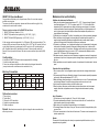
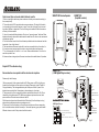
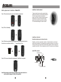
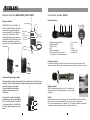
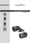
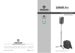
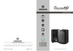
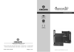
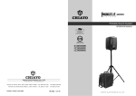
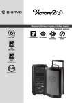
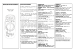
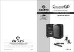
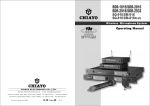
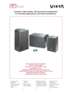
Portable
Sound System
OPERATION
MANUAL
OPERATION MANUAL
It has been RoHS Compliant
CHIAYO ELECTRONICS CO., LTD.
http://www.chiayo.com.tw
E-mail: [email protected]
OFFICE: 30, LANE 27, SEC.4. JEN-AL ROAD, TAIPEI, TAIWAN / TEL: 886-2-2741-5741
FACTORY: 88, CHUNG HSIAO STREET 2, CHIAYI, TAIWAN. / TEL: 886-5-271-1000
Printed in Taiwan, July 2009
FAX: 886-2-2752-5242
FAX: 886-5-276-7611
12I1173
SMART 300 Operation Manual
Congratulation and thank you for the purchase of this all-in-one ultra compact
portable sound system.
To ensure a trouble-free operation, please read this manual thoroughly to fully
understand its controls and functions.
There are various versions of the SMART 300 as follow :
1. SMART 300 Passive Speaker. (Fig.1)
2. SMART 300 portable sound system only ( VHF / UHF ) ( Fig.2 )
3. SMART 300 with USB Digital player. ( VHF / UHF ) ( Fig.3 )
All the versions can be equipped with 1 or 2 Wireless ( WR ) receiver module(s). The
wireless (WR) receiver module can be either VHF or UHF. The VHF module is a fixed
crystal single frequency type whereas the UHF module is a PLL synthesized type
with 16 preset frequencies ( identified by external 16 channel rotary switch(s) ).
Remark: It is also possible to have all the above versions without any wireless (WR)
fitted.
Configuration :
All versions of SMART 300 series comes equipped with the following :
1.A switch mode power supply.
2.One or two wireless microphones, either handheld or bodypack transmitter.
( except version with no wireless receiver module built-in )
.
Matching Transmitters
Transmitter types
Frequency band
Transmitters
Battery used
No. of channel
Beltpack
Handheld
UHF
SQ-816
SM-816 SQ-216
SQ-5016
SM-5016
SQ-916
SM-916 SQ-316
AAx3
AAx3
AAx3
AAx2
AAx2
9Vx1
9Vx1
9Vx1
16
Handheld
Beltpack Handheld Beltpack
VHF
SM-216
Q-1002 M-1002
SM-316
AAx3
9Vx1
9Vx1
9Vx1
1
Maintenance-free Lead Acid battery
Guidelines for maintenance-free Batteries:
1. Battery should operate at temperatures between 15°C ~ 50°C. To ensure a longer life span, it
should be kept between 5°C ~ 35°C. For optimum result, 20°C ~ 25°C will be ideal. When
temperature falls 15 degrees below zero, battery will undergo some changes in its chemical
contents and therefore cannot be recharged. Operating the battery at higher temperature will
result in higher capacity but shorter lifespan, whereas lower temperatures operation has a
longer lifespan but less capacity.
2. If the battery is not recharged 72 hrs after it is completely used, it will be permanently damaged.
3. When the battery is being charged, the internal gases will be electrolyzed into water at the
negative charge, maintaining the battery’s storage abilities with no water added. However,
erosion at the charged ends of the battery will cause poor performance.
4. The battery’s cycle lifespan ( no. of charge and discharge cycle ) is determined by the degree at
which power is dissipated., especially the degree of discharged each time it is used and the
recovery charging method. For normal use, the battery can be used for longer hours when less
power is dissipated each time and vice versa. At 25°C, maintenance-free batteries could be
charged 150 ~ 200 times at 100% discharge each time.
5. Decrease in capacity, internal short circuit, deformation in appearance, erosion of charged ends
and decrease in open circuit voltage are symbols indicating battery is approaching the end of its
life cycle.
6. When two batteries are used in parallel connection, the resistance of the cables should be kept
equal.
Properties of the Lead Acid Battery:
1. Has no memory effect. Can be charged at anytime, even when the recharge indication light is
not on.
2 .Performance and efficiency are affected by changes in the environment, especially temperature
and humidity. (Best operated between 20°C ~ 25°C)
3. Battery discharge naturally according to a certain pattern even not in use. For best performance
and a prolonged lifespan, it should be recharged every month even when not in use.
4. Under normal circumstances, battery could last for about a year.
5. When the battery’s life expires, possible indicators include internal short-circuit, decrease in
capacity, deformation in appearance, erosion of charged ends and decrease in operating
voltage.
Optional accessories :
1.Carrying bag.
2.Tripod stand.
3.Charger for UHF transmitter.
4.Companion powered speaker.
5.Wired microphone.
Remark: Manufacturer reserves the rights to change the above combinations
without prior notice.
1
User’s Precautions:
1. For first-time use, charge the battery for 10 hrs until it is fully charged.
2. To maintain performance and lifespan, if product has not been used for 3 months after the
initial shipment, please fully charge the battery.
3. Before each use, it’s advisable to charge the battery to its full capacity.
4. The average lifespan of the battery is one year. The user is advised to change the battery after
one year of use.
5. The current consumption is in direct ratio with load current. The more current consumption, the
less the operation time.
Remark:
The removal of the battery/ies must be done by an experienced qualified technician or by the
appropriate recycling operator!
18
Caution and tips on how to obtain the best results.
SMART 300
( Amplifier version )
SMART 300 Passive Speaker
1. Before inserting the batteries, please make sure that they are inserted according to
the correct polarity.
2. The audio cable of VHF transmitters also serves as antenna. The length of the cable
is cut according to the specific frequency range. Do not alter the length or mix around
the cable of different transmitters. The use of wrong audio cable will affect the antenna
efficiency of the transmitter!
3. Use only brand new Alkaline batteries. Do not use " general purpose " batteries, When
batteries are weak, replace all the batteries at the same time. Do not mix and use new and
old batteries together.
4. Position the receiver such that it has the least possible obstructions between it and the
transmitter. Line of sight is best !
5.The transmitter and the receiver should be as close as possible but not less than 1m.
6. A receiver cannot receive signals from two or more transmitters simultaneously.
7. Turn the transmitter off when it is not in use. Remove the batteries if it is not to be
used for a period of time.
8. Antennas form an integral part of the receiver and must be installed when in Operation.
A
F
PWR / MIC
B
LOW
K. WR1 channel selector
L. WR2 channel selector
G
C
AUX / USB
HI
TONE
A
K
H
C
A
L
B
CH1
D
D
CH2
E
F
E
I
A
G
EXT. SP
H
J
J
Fig. 1
Simple DIY Trouble-shooting :
No sound when one speaks into the wireless microphone
I
J
MIC IN
AUX IN
TONE
EXT. SP
DC IN
Main Power &
MIC Volume
AUX / MP3
WR Power &
Volume control
CHARGING indicator
Battery Compartment
cover release button
Fig. 2
SMART 300
( USB Digital Player version )
Please verify the followings:
1.Main power switch of the system should be ON. When power on LED not lighting up,
it means that the battery is either weak or not charged. Please plug in the AC cable to
Charge the battery. The rechargeable battery has a life span of about 2 years. If the
batteries have reached their life expectancy, please change to a fresh pair.
2.The power switch of the corresponding receiver module should be put to ON. This is
indicated by the lighted power LED. When two wireless microphones are used, both
power switches of the receiver modules must be ON.
3.Wireless microphone should be switched to ON and verify that the battery is okay. (
please refer to wireless microphone operating manual ).
4.Please verify that the frequency on the wireless microphone and the corresponding
built-in wireless receiver module are exactly of the same frequency group and channel.
5.Master volume control of the system should be turned on.
a
a
b
b
c
g
c
A
d
TONE
e
CH1
h
f
g
i
B
CH2
h
d
j
e
k
l
m
USB Dig it al Pla yer:
i
PLAY /
PAUSE
j
MODE
n
k
MIC IN
AUX IN
TONE
EXT. SPKR
DC IN
Main Power & MIC Volume
AUX / USB Power & Volume
WR1
WR2
Play / Pause
MODE selector
l
p
m
o
2
PLAY /PAUSE
Music Format:MP3 & WMA only
3
1 USB Jack ( Play starts automatically)
MODE
4
5
1
o
USB jack
Battery Compartment
cover release button
p CHARGING indicator
n
o
2 PLAY / PAUSE
3 4 EQ Modes : Normal / Rock / Classic / Jazz
4 UP
Fig. 3
5 DOWN
17
PWR / MIC
f
A. WR1 channel selector
B. WR2 channel selector
2
VHF Beltpack Transmitter M-1002
Operating procedures
After unpacking the unit for the first time, please charge the unit for about 4~5 hours
before any operation. This is absolutely necessary as the built-in rechargeable battery
might have been discharged naturally due to long shipment and storage time, even
though it has been fully charged in the factory prior to shipment.
Par ts & Fu nc tion s
Power Switch
To charge the battery, just plug in the DC end of the switch mode power supply into the
DC IN of the unit and charging will start automatically. During the charging process, the
charging indicator LED will flash GREEN. When GREEN LED stays glow permanently,
battery is then fully charged and normal operation could now be started.
To operate this portable sound unit, switch on the main POWER switch (H), which will
glow GREEN. However, the main POWER switch does NOT switch on the WR modules
as each of them has dedicated Power / Volume control switch indicated by WR1, WR2.
To operate each of them, you must switch them on accordingly.
When the Charging / Battery Status Indicator glows RED, it means the builtin rechargeable battery is weak and a recharge is necessary. While charging, the unit
could also be operated simultaneously.
Battery status
indicator.
MIC cable
MIC IN socket
MT
Battery
compartment
Battery compartment
cover
MIC capsule
MIC clip
Operating the built-in Wireless ( WR ) receiver modules
Input level Gain control adjustment
In the SMART 300 control panel, there are two designated power switch / volume
control knob for the built-in Wireless Receiver (WR). They are indicated by WR1 and
WR2 .
To use the 1 st wireless microphone, first switch on the main power switch (H), then
switch on the WR1 power / volume control switch, Red LED next to it will glow. Switch
on the corresponding transmitter ( RF ). Rotate the volume control knob clockwise and
amplified sound could be heard if voice is spoken into the transmitter.
To use the 2 nd wireless microphone, switch on WR2 power / volume control switch and
repeat the same operation as above.
By default, when the system is equipped with one WR receiver module only, it is always
controlled via WR1 switch, WR2 is then redundant.
For SMART 300 which comes with wireless receiver (WR) module, there are two
possibilities, namely the VHF or UHF version. The VHF receiver module is a fixed
frequency type. To operate the VHF version, just switch on the corresponding wireless
microphone(s) after switching on the WR1 or WR2 switch.
To operate the UHF version, which comes with 16 preset frequencies, please ensure
that the channel setting on the wireless microphone and SMART 300 receiver module(
D or E ) are the same before operation. Then perform the same procedure as above.
Low-impedance "MT" gain control is situated inside the beltpack transmitter. Gain
control port is an adjustable design that enables user to use microphones of different
output levels. To adjust the audio input levels, simply use a small screw driver to
switch the "MT" control till a desired level is chosen.
Battery Installation
M-1002 uses 1 piece of 9V battery. To install
new or replace the old battery, first open the
battery compartment cover, then insert the
new battery according to its correct polarity as
indicated. For longer operation hour, Alkaline
battery is recommended!
Belt Clip
This uniquely designed belt clip allows 360
rotation. Select the best position to achieve
optimum wearing comfort.
The above operation is only valid with SMART 300 version with built-in wireless
receiver (WR) module(s). Otherwise, the WR controls are redundant.
3
16
360 rotateable
belt clip.
Beltpack Transmitter SM-816(UHF) / SM-216(VHF)
Operating the dynamic wired microphone
Battery installation
There is a MIC IN jack with dedicated volume control for this portable sound unit. To
use a cable microphone ( dynamic only ), just plug the end with a phone jack plug into
MIC IN . Switch on the Power / volume control knob MIC ( H ) and rotate it clockwise,
amplified sound could be heard when voice is spoken into the cable microphone.
This transmitter uses 3 pieces of " AA " size
batteries (Alkaline battery is recommended ). To
install or remove the batteries, press the release
buttons at the edges of the transmitter to open or
close the cover as illustrated ( Fig.1 ).
Operating the USB Digital Player
Fig.1
Beltclip installation
Chargi ng point s
This specially designed detachable beltclip
allows the user to wear the transmitter with
antenna pointing upward or downward as
illustrated. To wear the transmitter with the
transmitter pointing upward, install the belt-clip
as in Fig.2. To wear the transmitter with the
antenna pointing downward, please install the
belt-clip as in Fig.3.
To use the USB 2.0 Player for playing music files(*.mp3 & *.wma format only), simply
plug your USB 2.0 into the port after the player has been turned on. " PLAY / PAUSE",
" MODE ", " Forward " and " Rewind " buttons can be used to control during USB is in
use. User is advised to have the USB format in " FAT " or " FAT 32 ". The built-in USB
player can not be able to read the MP3 files stored in your USB if it is not formatted
by either " FAT " or " FAT-32 ". Secondly, USB in use can only be detached after the
player has been shut off, preventing the USB from being possibly damaged.
Battery Charging
Internally, the SMART 300 SMART Slave contain 1 piece of 12V / 2.7AH maintenancefree lead acid rechargeable battery, which has no memory effect. When the battery is
weak, the power indicator RED LED will light up if the main power is switched on.
Chargi ng point s
Fig.2
Fig.3
To charge the battery, simply plug in the AC power supply, the charging process will
start automatically. While charging, the charging indicator will be in FLASH GREEN.
When battery is fully charged, the charging indicator will stay GREEN.
How to remove / replace safely the cell / battery.
Channel selection and gain adjust
Channel selector and gain adjust are hidden
in the designated cover of the front as
illustrated.
To make channel selection and gain adjust,
please press the designated cover and flip it
open as illustrated. Channel selection can be
made by rotating the selector with a small
screw driver.
Gain adjust for Lavalier and Headset
microphones can be done by adjusting the
MT switch, whereas GT switch is for the gain
adjust of electric Guitar and other highimpedance line level inputs.
15
MT
Channel
Selector
GT
* DO NOT expose the cell / battery to moisture or heat;
* Avoid contact of the cell / battery with water or liquid;
* DO NOT put the cell / battery in fire or expose to extreme temperatures and
magnetic fields;
* DO NOT reverse the polarity of the cell / battery or short circuit;
* Always replace in sets the cell / battery and with the same type;
FCC Radiation Exposure Statement This equipment complies with FCC radiation exposure limits set forth for an
uncontrolled environment.
This equipment should be installed and operated with minimum distance 20 cm
between the radiator & your body.
This device complies with Part 15 of the FCC Rules. Operation is subject to the
following two conditions (1)This device may not cause harmful interference, and
(2)this device must accept any interference received, including interference that
may cause undesired operation. 4
Battery replacement / installation of Smart 300
Installation of cable restraint
Step 1:Press and release the cover from the battery compartment.
To prevent contact noise caused by constant tension
applied to the connector,,a cable restraint is designed
such that tension is totally reduced when it is
properly used. When the audio cable go through the
cable restraint, it could prevent sweat from going
directly into the electronic board via the connector.
This is another advantage of the cable restraint.
Step 2:Pull out the battery.
Installation of Lavalier /
Headset microphones or instrument inputs
Step 3:Slide the new battery into the compartment in the same direction as how
the previous one was taken, with the “+”,”-” corners facing in & up.
Depending on customer requirements, Lavalier / Headset microphone or instrument
inputs could be connected to the transmitter via the audio input connector. User is free to
choose the various input sources but is advised to take note that connector used must be
compatible to each other. The pin configurations of mini XLR connector are as follow figure.
mini XLR connector
LED INDICATOR
GT IN
OFF
Step 4:Put the cover back and the replacement / installation is completed.
ON
2
3 4 1
POWER
ANTENNA
MT IN GND
POWER
SWITCH
PHANTOM POWER
Note: Please make sure the battery is installed in the correct direction to
avoid possible damages to itself and the amplifier.
5
14
Beltpack Transmitter SM-916(UHF) / SM-316(VHF)
UHF Handheld Transmitter SQ-5016
Battery installation
Parts and functions
Antenna(SM-916)
Battery status
Indic ator
Power swit ch
Cable
restrain t
5016
SM-916/SM-316 use a 9V battery. To
insert the battery, first open the battery
compartment cover by pressing the
cover downward till the door flips open
by itself (see below picture). When
installing the battery, please beware of
correct polarity. To put back the cover of
the battery compartment, one has to
press the cover in upward direction until
it is locked.
Audio in put
Connector
Battery
Compartment
Mik e clip
Capsuale
7. Lock / Unlock
8. Set
9. Up
10. Down
11. Charging port
12. Name plate
1. Microphone capsule module
2. Battery status LED
3. ON/OFF switch
4. LCD
5. Battery compartment
6. Rotating protective cap for controls
(also serves as color identification cap)
Changing of capsule
First unscrew the metal grill from the housing and take out the capsule to be replaced. Then
insert a new capsule. Either dynamic or condenser type can be chosen from location to location.
Fig.1
Channel selection and gain adjust
Channel selector and gain adjust are hidden in the designated cover of the front as
illustrated. To make channel selection and gain adjust, please press the designated
cover and flip it open as illustrated.
Channel selection can be made by
rotating the selector with a small
screw driver.
Gain adjust for Lavalier and Headset
microphones can be done by adjusting
the MT switch, whereas GT switch is
for the gain adjust of electric Guitar
and other high- impedance line level
inputs.
Battery installation
SQ-5016 microphone requires 2 pieces of " AA " size batteries to
operate. Please insert the batteries according to the correct polarity
as indicated.
Caution
MT
Channel
Selector
Many batteries are known to have leakage problem of conductive and corrosive liquid. Please
observe the rule to remove the batteries if they are not to be used for a longer period.
Due to various unstandardized sizes ( diameters ) of " AA " batteries, this battery compartment
is designed to accommodate the most common Alkaline batteries only.
GT
13
6
7
12
UHF Beltpack Transmitter SM-5016
Handheld Transmitter SQ-916(UHF) / SQ-316(VHF)
Parts & functions
Parts & Functions
7
8
9
10
11
Antenna
Battery weak / audio mute indicator
Audio mute switch
Mini-XLR connector
Power ON / OFF switch
LCD display
Charging port
Cover release button
Charging contacts
Lavalier microphone
Mic clip
1. Capsule with metal grille
2. Battery indicator
3. Sensitivity switch
4. Power on/off switch
5. Battery cover
7. Color cap
Battery installation
12
13
14
12
13
14
15
16
SET
UP
DOWN
GT
MT
Pre
ss
1516
SQ-916/SQ-316 use a 9V battery for power. To change or replace the battery,
please remove the color cap first, then press the bottom of battery compartment to
release the cover as shown below.
Battery installation
Sensitivity switch
SM-5016 uses 2 pieces of " AA " size batteries (Alkaline battery is recommended ). To
install or remove the batteries, press the release buttons at the edges of the transmitter to
open or close the cover as illustrated below.
This microphone has a sensitivity switch. For close mouth singing or normal speech,
please put the switch to L ( Low ) position. For tripod-mount speech, please put the
switch to N ( Normal ) position.
L
N
L
Low Sensitivity
11
Normal Sensitivity
8
N
Handheld Transmitter SQ-816(UHF) / SQ-216(VHF)
VHF Handheld Transmitter Q-1002
Parts and Functions
Parts & functions
Battery status
LED indicator
Battery compartment
cover
Color cap
Metal Grille
( Capsule module inside )
Power Switch
Battery Installation
1. Capsule with metal grille
2. Battery normal indicator (Green)
3. Battery low indicator (Red)
4. Power on/off switch
5. Channel switch
6. Charging port
Q-1002 uses 1 piece of 9V battery. To install new or replace the old battery, First
unscrew the battery cap from the battery compartment, then insert the new battery
according to its correct polarity as indicated. For longer operation hour, Alkaline
battery is recommended!
P r e ss
Battery installation
SQ-816/SQ-216 transmitter requires 3 pieces of " AA " size battery to operate.
Please insert the batteries according to the correct polarity as indicated. To open the
battery compartment, press and slide down the cover until it clicks and locks. Further
sliding movement will remove the cover.
After putting the battery cover back to the housing , slide the switch to "ON" position as
shown below.
slide to "ON" position
As soon as the power is on, the battery-status indicator will give flash, indicating a
normal operation. If there is no flash, it indicates either power supply is not available
or battery is installed wrongly.
After switching on, the Therefore signal indicator LED(s) of matching receiver will light
up, indicating the microphone signal transmission is in normal operation.
Switch off the power when the microphone is not in use, meanwhile, remove the
battery out of microphone if it is not to be used for an extended period.
9
10