1
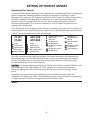
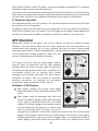
DC Genset/Watermaker
Operations Manual
19009 61st Ave. NE #4,Arlington, WA 98223
Phone: (360) 435-6100, Fax: (360) 435-3210
E-Mail: [email protected], Web: www.balmar.net
TABLE OF CONTENTS
Setting Up Your Genset
Unpacking Your Genset .................................................... 1
Preparation For Installation
Space & Ventilation Requirements ................................ 2
Ventilation ............................................................................2
Exhausting............................................................................2
Fuel System ........................................................................2
Maintenance ........................................................................2
Installation Procedures
Seawater & Freshwater Supply ...................................... 3
Exhaust System ..................................................................3
Starting System ..................................................................4
Cooling System....................................................................4
Fuel System ........................................................................4
System Alternator ..............................................................4
Voltage Regulator ..............................................................4
Alternator Direct Coupling Device ................................5-6
Key Panel ............................................................................7
Parts Required For Installation
Mounting Genset................................................................ 7
Seawater Supply ................................................................ 7
Exhaust System.................................................................. 7
Starting System.................................................................. 7
Troubleshooting ........................................................................ 8
Warranty ...................................................................................... 8
Aqua Pac Voyager Operations
Introduction ........................................................................ 9
Central Processing Module ............................................ 10
Pre-Filtration Module ...................................................... 10
Reverse Osmosis Module .............................................. 10
Pressure Regulator ........................................................ 11
Control Panel.................................................................... 11
Feedwater Pump ............................................................ 11
Emulsion Removal Module ............................................ 11
Plankton Filter Assembly .............................................. 11
UV/Charcoal Sterilizer .................................................... 11
Supplemental Filters ...................................................... 11
Freshwater Flush Assembly .......................................... 11
Watermaker Specifications .......................................... 12
Replacement Parts ........................................................ 12
Desalinator Operation
Initial Watermaker Startup............................................ 12
Routine Startup .............................................................. 13
Routine Watermaker Shutdown .................................. 14
Prolonged Watermaker Shutdown .............................. 14
Temperature Effects on Performance.......................... 14
Freshwater Output Correction ...................................... 14
Properties Of RO Water.................................................. 15
Watermaker Installation
Central Processor Module Mounting............................ 15
Product Water Outlet Connection ................................ 16
Waste Product Water Outlet Connection .................... 16
Input 12VDC Power Connection.................................... 16
Connecting Electrical Control Cable ............................ 16
Watermaker PRe-Filtration Module.............................. 16
Water Connections .......................................................... 17
Reverse Osmosis Module Assembly/Installation ...... 18
Pura UV Disinfection/Filtration System ...................... 19
Prior To Running DC Genset
Electrical Connections .................................................... 20
High-Output Alternator Cables ...................................... 20
Cooling and Lubrication Systems ................................ 21
Fuel System ...................................................................... 21
System Control Panel .................................................... 21
Toggle Speed Control ...................................................... 21
Regulator Programming ................................................ 21
Starting Engine ................................................................ 21
Automatic Alarm Shutdown .......................................... 22
Activation of Charging System ...................................... 22
To Terminate Operation.................................................. 23
APV Checklist
Activation of APV............................................................ 23
High Pressure Test .......................................................... 24
Manual Override Mode .................................................. 24
Filter Pack ........................................................................ 25
Final Thoughts ................................................................ 25
CAUTION!
Please read ALL of the specific information included in this manual. Failure to do so could
result in poor genset performance, mechanical and/or electrical damage, and serious injury
to the operater and/or installer. Improper installation and/or operation may also nullify the
manufacturer's warranty (see the "Warranty" page in this manual).
SETTING UP YOUR DC GENSET
Unpacking Your Genset
Your genset was carefully packaged and inspected prior to shipping. Before uncrating the
genset, inspect the shipping container carefully for any signs of damage. If major
damage to the exterior of the shipping container is noted, notify the driver of the delivery
vehicle immediately. Arrangements for inspection by a claims representative of the
shipper should be arranged with the driver or with a shipping company customer
services representative. If a camera is available, it may be helpful to document any
damage with photographs.
Once inspection of the shipping crate’s exterior is complete, the crate may be opened by
unscrewing and removing the top panel. Inspect for any shipping damage and document.
Your DC Genset package will contain the following:
APC-750
APC-850
PC-750
PC-850
1. Engine
2. Control Panel
3. Expansion Tank
Mounting Kit
4. Owner’s Manual
1.
2.
3.
4.
5.
Engine
Control Panel
Expansion Tank
APV Control Panel
Pre-Filter Pack
6.
7.
8.
9.
10.
11.
Pre-Filter Mounting Kit
Water Puppy
Kitz Valve
Hayward Valve
RO Membranes
RO Membranes Order
Form
12. RO Pressure Vessels
13. RO Membrane
Mounting Kit
14. RO High-Pressure
Fittings
15. RO Low Pressure
Fittings
16. Bio Scrub Hose Kit
17. Cat Pump Oil
18. Owner’s Manual
Once the contents of the shipping container have been inventoried and inspected for
shipping damage, the four side panels may be removed by unscrewing the retaining
screws. The genset can be removed from its supporting panel by removing the lag
screws fastened at the four mounting feet.
CAUTION: The genset weighs approximately 190 lbs. alone and in excess of 225 lbs. with
the watermaker Cat Pump installed. DO NOT attempt to move the genset without
adequate assistance. Failure to follow this guideline could result in damage and/or
injury.
If possible, the genset should be transported to its installation location with the
assistance of a heavy duty hoist. The installation location must be capable of supporting
a weight load well in excess of the genset and watermaker pump.
Notes:
-1-
PREPARATION FOR INSTALLATION
Space and Ventilation Requirements
Several issues should be addressed when determining the optimal installation location for
your DC genset: Ventilation, Cooling, Fuel Supply, Exhausting, Ease of Maintenance and
Repair, Protection from the Elements.
Ventilation: Both the genset’s diesel engine and high-output alternator require substantial
airflow to ensure adequate cooling. The installation site should be free of any potential
obstructions that could inhibit airflow. If
airflow at the installation site is
compromised, it may be necessary to
introduce additional airflow with the
addition of a fan or blower. Should you
want the fan or blower to operate only
when the genset is in operation, power
may be pulled from the genset’s oil
pressure switch or from the positive side
of the genset’s ignition switch.
Fuel System: Fuel input fittings at the
engine are 1/4" in and 1/4" out. Preferred
installations include a primary fuel filter
with water separator (Racor type) before
the engine. An electric or manual fuel
pump and inline filter is installed on the
genset. Adequate room for fuel filters and
fuel pump must be provided.
Exhausting: The DC genset is designed to
be matched with a 13/4” exhaust. The installation site should provide ample space for the
inclusion of the exhaust system. Each system will vary, based on ducting material, muffler
type and thru-hull. Exhaust can be directed toward the front or rear of the genset.
Maintenance: The DC Genset is designed to provide access to most commonly required
service points on the same side of the genset. Care should be taken when locating the
installation point to ensure that the access friendly side of the genset be located within
easy reach of the operator.
CALIFORNIA
Proposition 65 Warning
Diesel engine exhaust and some of its constituents are known
to the State of California to cause cancer, birth defects, and
other reproductive harm.
-2-
INSTALLATION PROCEDURES
Seawater and Freshwater Supply
Seawater supply hose must be a minimum of 5/8" ID and must not be obstructed by
undersized sea water strainers, fittings, or sea cock valves. We recommend seawater hose
and fittings be a minimum of 3/4". The larger the sea strainer, the better. Do not share the
seawater inlet with the main engine through-hull unless a sea chest is available.
If your system is fitted with a watermaker, ensure that the seawater intake is located
forward of the head discharge or any other discharge that could foul your watermaker’s
supply source.
If the unit is installed below the waterline, a vented loop is required. The seawater supply
line feeding raw cooling water into the system must be routed to prevent siphoning of raw
water through this line into the exhaust system, filling the muffler and engine cylinders.
This line should be routed at least 12 inches above the waterline and an anti-siphon break
installed the top of its loop. This loop should be high enough above the waterline to ensure
that it remains dry even while heeling.
A small freshwater supply tank (expansion tank), bracket, and 10' of 3/8" clear hose are
supplied with the unit and should be mounted level with the genset’s heat exchanger.
Exhaust System
Engine exhaust elbow is 13/4”. Exhaust line installations will vary considerably and each
must be designed for the particular installation. The prime requirement is to provide an
outlet line with a minimum of restrictions, situated in a manner that ensures seawater,
rainwater and condensation cannot get back into the cylinders of the engine. Most exhaust
systems today use a water lift muffler such as the Vernay or Vetus type.
-3-
Starting System
The DC genset is equipped with its own dedicated charging system to support an
independent starting battery. Should you choose to utilize a dedicated battery, or start the
genset with the ship’s battery, ensure that battery cables are properly sized to support the
genset’s starting load. The battery (+) lead will connect to the positive post of the small
alternator attached to the genset’s engine. A jumper wire is already connected to the
starter solenoid. The negative battery lead attaches to the lower starter mounting post.
Fuel System
Fuel is supplied to the genset via the main diesel tanks or a dedicated genset fuel tank.
High quality 1/4” fuel line should be used to supply diesel to the genset. Fuel pre-filters and
fuel pumps, as described on the preceeding page, should be used as needed. A 1/4” fuel
return line is also required.
Coolant System
The genset is equipped with an onboard heat exchanger unit with an off-engine coolant
recovery tank. The genset’s coolant system should be topped off after installation with a
50/50 mixture of water and coolant. The coolant recovery tank must be installed within
21" of the cap/manifold. This assures the cooling system will retain all fluids during normal
operation.
System Alternator
The DC genset is equipped with a Balmar high output alternator and the Max Charge
voltage regulator. An alternator temperature
sender is installed on the alternator to protect
it against over-heating. This alternator is a
single output alternator. If your alternator
model has a jumper strap supplied between
the terminals, it must be left in place. The
positive cable will connect to one of the ouput
posts. The negative cable should be
connected to one of the two bolt holes near
the rear bearing at the center of the
alternator. These cables should be properly
sized and supported to avoid undue strain on
the altnerator and fitting. For detailed
information, see ‘Alternator and Regulator
Owner’s Manuals’ in the manual.
Brushless 98-Series Alternator
Voltage Regulator
The Max Charge voltage regulator is included with the DC genset in its own shipping
container within the crate. The regulator includes a 54" wiring harness, which allows
installation on stringer or bulkhead near the genset. The brown (switched) wire in the
regulator wiring harness should be connected to the (brown) switched source wire located
near the speed control box and oil pressure switch. Switched source wire is identified with
a marking tag.
-4-
Alternator Direct Coupling Device (Lovejoy #LF4 Coupler)
The alternator is coupled to the genset engine via a flexible torsional coupling (Lovejoy
#LF4). The coupling is installed prior to shipping and should require no user adjustment
thereafter.
Should you need to remove and replace the alternator and coupling, re-installation will
require strict adherence to the following procedural guidelines:
1. Inspect all contact surfaces on the Lovejoy coupler (bare metal surfaces on the
rubber coupling unit) for oil, dirt or other contaminants. Clean those surfaces
thoroughly with a medium grit sandpaper and wipe clean. Clean flex ring adapter
(metal ring attached to the engine flywheel) and pulley flange as well.
2. The Lovejoy is connected to the flex ring adapter under compression. When
installing the Lovejoy coupling you will find that the threaded holes on the flex ring
will not necessarily align with the Lovejoy without some manipulation of the
coupling.
3. Attach the Lovejoy to the
flex ring with a single
25mm capscrew. Turn the
capscrew a couple of
rotations -- just enough to
ensure proper threading.
4. One-by-one, insert the
Shows correct and incorrect axial coupling alignment.
remaining capscrews and
turn just enough to ensure proper threading. It may be necessary to compress the
Lovejoy to align with the threaded holes on the flex ring. Once all of the capscrews
have been started, each can be tightened to 20 ft.lb. Inspect coupling attachment
for proper alignment, as shown in illustration above.
Alternator Attachment
1. Ensure that the aligning capscrew is attached to the center bore on the tensioning
crown of the alternator. Align alternator so the flange in the pulley assembly fits
evenly inside the center hole in the Lovejoy coupling and the head of the aligning
capscrew fits in the indexing hole in the alternator bracket.
2. Once aligned, insert the 3/8” hex bolts in the two remaining holes in the alternator
tensioning crown (on either side of the indexing screw). These bolts will thread
into the alternator bracket. There may be some play in the bore containing the hex
bolts. Don’t be concerned. The head of the indexing capscrew will ensure proper
alignment.
3. Insert the 1/2” hex bolt at the remaining alternator foot and thread into the
alternator bracket. Torque the alternator retaining bolts to 38 ft.lb.
4 Insert the Nordlock (locking washers) into the radial cavities of the Lovejoy
coupling. (Inserting the washer at an angle to the coupling makes it easier to
insert the washers).
5. Align the screw holes of the Lovejoy with the threaded holes in the pulley by
turning the alternator fan.
-5-
5. Once aligned, insert the 30mm Capscrews into the three radial cavities in the
Lovejoy. Tighten each capscrew just far enough to ensure proper threading until
all screws are properly aligned and threads are started.
6. When all three capscrews are in place, Tighten to 20 ft.lb. It may be necessary,
once all capscrews are in place, to turn the crank pulley on the engine to access
all of the capscrews for torqueing.
7. Inspect the Lovejoy for
proper alignment as
illustrated
at
right.
Loosen capscrews and
re-tighten, if necessary,
to ensure that the
Lovejoy is free from
distortion.
Shows correct and incorrect radial coupling alignment.
8. Re-check torque.
9. Replace Cat Pump platform.
10. Re-connect wiring connections at alternator as described in the alternator manual
included in the genset instructions.
Notes:
-6-
Key Panel
Electrical Connections for 12VDC motor functions are made at the molded plugs at the
engine. One 20' extension cable is supplied with each system. There is a 25-amp fuse at
the engine for panel and wire protection. The engine is supplied with oil pressure and
temperature switces, and will shut down the engine in the advent of a malfunction. A red
LED on key panel would indicate this.
Key Panel includes:
1. Key Switch
2. Hour Meter
3. Toggle-Adjustable Speed Control for manual control of engine throttle
4. Toggle switch to turn ON-OFF system alternator
5. Digital voltage meter indicating system voltage - gray wire at ESC box should be
connected directly to positive post at battery bank Wire should be fused near battery
at three (3) amps..
6. Mini toggle switch for ON-OFF system voltage meter
7. Pre-Heat, Run, and Alarm LEDs.
PARTS REQUIRED FOR INSTALLATION
Following is a general list of parts needed for installation. This is just a general list, as all
boats are different and installation is unique to each one.
Mounting Genset
1. (8) 5\16 Hex Bolts or Lag Bolts, w/nuts and washers as needed. Primary Fuel Filter
and Water Separator w/ fittings
2. 1/4" Fuel Hose w/clamps (fuel supply)
3. 1/4" Fuel Hose w/clamps (fuel return)
Fittings as needed to install hoses to boats fuel system
Seawater Supply
1. Seawater Through-Hull fitting (3/4" or larger)
2. Seawater Intake Valve (ABYC approved)
3. Sea Strainer (minimum ¾")
4. Vented Loop fitting, optional (not necessary if mounting above water line).
5. Fittings as needed to make up intake valve, sea strainer and through-hull
6. 5\8" or 3\4" Intake Hose w/clamps
Exhaust System
1. Exhaust Through-Hull fitting (1¾")
2. Water Lift Muffler (1¾")
3. 13\4" Marine Exhaust Hose w/clamps
Starting System
1. Start Battery w/lugs
2. Start Battery Cables (minimum #6 AWG) w/terminals
-7-
PARTS REQUIRED FOR INSTALLATION (Continued)
Battery Box
Alternator System
System Battery Cables (minimum #1\0 AWG - determined by length of run & percentage
of line loss).
TROUBLESHOOTING
Balmar equipment manuals contain a user friendly troubleshooting section. This information is also
available at our web site: www.balmar.net. Personal assistance in troubleshooting equipment is
available through our Technical Support Department via E-mail ([email protected]) or phone (360435-6100, ext. 3). Our hours of operation are Monday - Thursday, 7:30 am - 5:30 pm PST. We are
closed Friday - Sunday. There are endless possibilities that can cause a system to not operate
properly, other than equipment defect. It is the responsibility of the owner to either troubleshoot the
system or hire a qualified professional to do so.
Non-Warranty Repair: If failure is found to not be covered under the terms of this warranty, customer
will be presented with price to repair / replace. If repair / replacement is declined, equipment will be
returned to customer as stated under #4, Return to Customer, or will be disposed of upon request.
Loaner Equipment: Balmar does not provide equipment for loan to be used while failed equipment
is undergoing analysis. If replacement equipment is required prior to warranty analysis, new
equipment can be purchased. Used equipment may be offered for sale, subject to availability.
LIMITED PRODUCT WARRANTY
BALMAR warrants to the original consumer/purchaser the product is free from any defects in material or workmanship for a period of
one year from the date of purchase. This warranty DOES NOT apply to defects or physical damage resulting from abuse, neglect,
accident, improper installation, wiring, or repair, alteration, modification, or unreasonable use of the products resulting in breakdown,
cracked or broken cases, parts damaged by fire, water, freezing, collision, theft, explosion, rust, corrosion, overheating or items
damaged in shipment in route for repair. BALMAR assumes no responsibility for consequential damage or loss or expense arising from
these products or any labor required for service or repair. Alternators are not covered when used with manual regulation devices.
Following are requirements for determining warranty coverage:
1.
Proof of Purchase: All Balmar equipment is production dated. This date is not adequate for warranty consideration, as new
product can age significantly prior to end user purchase, installation, and placement in service. Proof of purchase is
required for accurate calendar consideration.
2.
Analysis of Failure: All equipment will be factory analyzed to determine warranty status prior to replacement or repair.
Contact Balmar for return authorization (RA) number. Balmar can not be held responsible for any product sent without
proper identification, return address, and RA number clearly marked on the package. Ship equipment prepaid to the
location specified by Balmar. This warranty is not extended to costs of troubleshooting, including time, labor, or
communication costs incurred either with Balmar or other marine specialists.
3.
Determination of Warranty: If the equipment is found, upon analysis, to have failed under the terms of this warranty, it will
be repaired or replaced. Balmar reserves the right to determine whether to repair or replace components. Allow 30 days
A.R.E. (after receipt of equipment - expedited service is available upon request whenever possible). This warranty is in lieu
of all implied or verbal warranties as to the merchant ability or fitness for a particular application. No person is authorized
to repair, modify or assume additional obligations for warranty without the written authorization of a Balmar corporate
officer.
4.
Return to Customer: Once analyzed, equipment will be returned by surface freight to continental US destinations.
International and offshore 'ship to' addresses, as well as 'rush' and expedited shipment requests, will require credit card for
payment of freight charges.
THE ABOVE LIMITATIONS MAY NOT APPLY TO YOU. SOME STATES DO NOT ALLOW LIMITATIONS ON HOW LONG AN IMPLIED WARRANTY
LASTS. NO PERSON, AGENT, DEALER IS AUTHORIZED TO GIVE ANY WARRANTY OR REPRESENTATION ON BEHALF OF BALMAR UNLESS
MADE IN WRITING BY AN OFFICER OF BALMAR.
-8-
Aqua Pac Voyager
Operations Manual
Pre-Filtration Module
Control Panel & CPM
Feedwater Pump
RO Membranes
Introduction
The Aqua Pac Voyager is a revolutionary concept in providing fresh water from seawater for
pleasure boats and for remote residences and encampments. The integrated desalinator
is nominally rated at either 20 or 40 gallons per hour. The APV system is modular in design,
combining required components, whether installed on a Balmar PC-750 or PC-850 DC
Genset or used on its own.
Aqua-Pac desalinator operates on the principle of reverse osmosis. The ions (salt) in
seawater tend to form into clusters, which are many times larger than the individual pure
water molecules. Under pressure, the pure water molecules are forced through a semipermeable membrane leaving the ion clusters behind. Although a simplification, this is
basically how reverse osmosis works.
In actual practice, the feed-water is drawn from the source through a coarse strainer,
through three stages of filtration, and delivered to the inlet of a three cylinder reciprocating
pump which is belt or direct-driven by the engine. This "high-pressure pump" forces the
feed-water through the membrane, through a variable restrictor or "RO Pressure Regulator",
and out to discharge. The RO pressure regulator creates the back pressure applied to the
feed-water in the high-pressure vessel.
While ionized feed-water, under pressure, is being forced over the membrane, pure water
is permeated out of the membrane and is called "product water". The product water passes
through a flow meter, which indicates the amount being produced, in gallons per hour.
-9-
From the flow meter, the product water enters a chamber called the "salinity cell" where
two probes measure the electrical resistance of the product water. The residual ion content
of the product water is inversely proportional to its electrical resistance, totally de-ionized
having infinite resistance. Typical resistance of the product water will be in the
neighborhood of 1500 ohms. The purity of the product water may also be expressed in
mhos where the value would be the reciprocal of that in ohms. Additionally, the purity may
be expressed as parts per million of total dissolved solids. The PPM value (at levels found
in product water) is roughly half of the value in micro-mhos.
If the salinity cell and associated circuitry determines that the product water is of
acceptable quality, an electric "diversion" valve is opened and the product water is allowed
to flow into whatever storage facilities are provided. Should the vacuum at the inlet of the
high pressure pump become abnormally great due to clogged pre-filters or some other
cause, an automatic circuit will stop the system and activate a "HIGH INLET VACUUM" light.
RO pressure is indicated on the RO pressure gauge. Pressure in excess of 1000 PSI will
trigger the pressure relief valve.
Central Processing Module (CPM)
The Central Processing Module is equipped with the system control switch, start button
and all annunciator lamps. As will as the product water flow meter, salinity probe (MPU) in
which water quality is measured, and the electric diversion valve (Burkheart valve) which
directs potable product water into the storage tanks. The front of the CPM forms the
system's main control panel.
Pre-Filtration Module
The Pre-Filtration Module is a three-stage filter system that removes suspended particulate
matter from the incoming feed-water. Efficient pre-filtration contributes greatly to
prolonging RO membrane life. The first stage consists SS strainer screen (Plankton filter)
housed in a clear plastic bowl. The second stage is a 577 square inch, pleated-paper 50micron filter. The third stage is a 5-micron filtration cartridge.
The SS strainer screen (Stage 1) can be cleaned and reused over again. The 50 and 5micron cartridges should be replaced as needed. You may want to save the best of the
used, 5-micron filters for the cleaning process. A relay module mounted on the pre-filter
assembly operates the electric clutch at the feedwater (Cat) pump and the pre feed pump
(water puppy). The primary system fuse and over-ride switch used when performing the
cleaning and preserving tasks, as well as terminal strips for convenient wiring are also
mounted on this relay module.
Reverse Osmosis Module (ROM)
The Reverse Osmosis Module is where de-ionization takes place. Feed-water (seawater)
under pressure flows out the high-pressure pump module and through the ROM highpressure vessel past the reverse osmosis membrane inside the pressure vessel. Pure
water molecules permeate through the membrane fabric where they are collected and
manifold to a tube in the center of the membrane.
This "product water" then flows back into the Central Processing Module for further
processing. Meanwhile, the feed-water that did not permeate through the membrane flows
to the Pressure Regulator Module and is subsequently discharged as waste overboard.
- 10 -
Pressure Regulator
The Pressure Regulator consists of a manual pressure regulator and a pressure gauge
mounted on the control panel. The regulator maintains the proper back pressure on the
membrane.
Control Panel
The Control Panel permits operation and monitoring of the system from a convenient
location such as in the living quarter of a boat.
Feedwater Pump
The Pre-feed pump consists of a separate relay controlled pump that forces feed-water
through the pre-filters. Installation of a feed-water pump will decrease pre-filter
maintenance, system noise and vibration and RO pressure pump wear. If either the engine
or the Pre-Filtration Module must be mounted more than two feet above the feed-water
source level, a Feed-water Pump Module will be required as well as a check valve. A Feedwater Pump Module is recommended for all installations.
Emulsion Removal Module (ERM) Optional
This unit removes oil or silt from the feed-water, to further protect the RO membrane. This
element should be replaced as soon as oil is detected or every year during normal
servicing.
Plankton Filter Assembly Optional
This is a 50-micron SS element that works more efficiently than the sea strainer and never
needs to be replaced -- just cleaned on a normal basis. This will not replace a sea strainer.
Ultraviolet/Charcoal Sterilizer Optional
Although the RO process is very effective at removing bacteria and other pathogens from
the feed water, a UV/Charcoal Sterilizer can be added that will function as a second line of
defense against any micro-organisms that may have penetrated the RO membrane. The UV
Sterilizer is recommended anytime the desalinator is going to be used in brackish or
sewage contaminated waters. The charcoal element removes foul odors and tastes in the
product water. The charcoal filter is rated at .5 micron and should be replaced every year.
It is a special style charcoal filter, call Balmar for replacement. The UV bulb should be
replaced every 2000 hrs. or every two years. After recommended replacement time, the
spectrum of the light will shift and cause insufficient radiation of the bacteria and viruses.
Supplemental Filters
A 5 micron filter is standard with the Aqua-Pac. 5 and10 micron filters are available in the
standard size. Larger surface area filters are also available in various micron sizes. Media
filters are available for land based or commercial applications.
Freshwater Flush Assembly Optional
This is a charcoal filter and three-way valve assembly designed to be installed onto the
fresh water system for flushing the salt water out of the desalinator. Not intended for long
shut down periods. Up to one month before re-flushing is required.
- 11 -
Watermaker Specifications
Feed-w
water pH Range: 3-1
11
Feed-w
water Temperature Range: 40° to 100°F (4.4°C to 37.8°C)
Membrane Salt Rejection: 98.6 % or greater
Maximum Operating Pressure: 800 PSI
Cpm Switched Accessory Terminal Output: 6 Amps @ 12 VDC
High Pressure Pump Crankcase Lubricant: Balmar P/N 334-0
010
High Pressure Pump Crankcase Capacity: 12 oz
*All performance specifications are with feed-water salinity of 35,000 PPM, feed-water pH of 8, feed-water
temperature of 77°F (25°C), and operating pressure of 800 PSI. Product water output will decrease with lower feedwater temperatures. Rated output at a given temperature is +/- 15%.
Replacement Parts
Genuine Balmar replacement parts as well as modules and accessories are available from
authorized Balmar dealers. As a convenience to Balmar product users, replacement parts
are also available directly from Balmar Products.
WARNING: Use of other than genuine Balmar replacement parts may impair the
performance and/or inherent safety of the system and may also void the warranty.
Replacement parts obtained from dealers are not necessarily genuine.
Desalinator Operation
Initial Watermaker Startup
NOTE: If there is a chance that the ROM will be subjected to freezing temperatures during
the lay-up, remove the high pressure vessel, seal the vessel ports with the caps supplied
in the Cleaning/Biocide Kit, and place the vessel in a storage location whose temperature
will be maintained between 50°F (10°C) and 75 °F (24°C). A food grade preservative is
available from Balmar, should removal be difficult. This acts as an appropriate anti freeze.
But it is not rated below 20 F.
CAUTION: Allowing the membrane to freeze will cause permanent damage.
The following procedure should be used for new installations and for returning systems
to service after a prolonged shutdown.
1.
De-e
energize the Desalinator circuit breaker. Ensure that there are no explosive
vapors present in any of the compartments where components of the Desalinator
are located. (This step is primarily for installation in hazardous locations such as
offshore oil platforms and gasoline powered boats.)
2.
Ensure that the high-pressure pump crankcase is filled to the red dot on the oil
level indicator.
3.
Set the Product Water Control valve to normal.
4.
Open all feed-water inlets.
- 12 -
5.
Start the engine.
6.
Set the Master System switch to "manual" at the control panel.
7.
Turn the RO pressure valve all the way counter-clockwise, to ensuring that no
membrane preservatives enter the product water storage tank.
8.
Press and release the desalinator start switch.
9.
Check the entire system for leaks. If any are found, stop the system and correct
as necessary.
10. If the system should stop automatically, refer to “Troubleshooting Section” for
possible causes.
11. After the system has run for 2 hours, slowly turn the RO pressure valve clockwise
until the RO pressure gauge registers 800 PSI or rated flow of the membrane (i.e.
20 G.P.H.) whichever occurs first.
12. Check for leaks.
13. Wait for the product water flow meter to stabilize. Adjust the RO pressure valve so
that the flow meter indicates approximately the proper product water flow for the
given feed-water temperature. (Refer to Section 1.4)
14. Again, check the entire system for leaks.
Routine Start-Up
The following procedure should be used if the desalinator has been operated within the
previous 14-day period. For newly installed systems or systems that have been laid up for
more than 2 weeks, refer to "INITIAL START-UP PROCEDURE". (In general, systems should
be operated at least once every 14 days, as some of the system components deteriorate
over long periods of idleness. This is especially true of the RO membrane, although the
prolonged shut down procedure will help retard the deterioration.)
WARNING: This desalinator during the course of normal operation generates electrical
arcing that could ignite explosive vapors. Do not attempt to operate the system if any
explosive vapors are present.
1. Ensure that there are no explosive vapors present in any of the compartments
where components of the desalinator are located. (This step is primarily for
installations in hazardous locations, such as offshore oil platforms and gasoline
powered boats.)
- 13 -
2. Ensure that all feed-water valves are open.
3. Start the engine. Allow a few minutes to warm up.
4. Activate the desalinator start switch.
5. Verify that the "CLUTCH ENGAGED" light is on.
Periodically, verify that the product water flow--meter indicates approximately the proper
product water flow for the given feed-water temperature. (Refer to Section 1.4) (This should
be done immediately whenever it is suspected that the feed-water salinity has changed such as when cruising from a river to open ocean.) Do not exceed the rated production of
the membrane. Adjust the RO pressure regulator to correct.
WARNING: Ingestion of oil and some chemicals are harmful to the RO membranes. Do not
operate the system using feed-water sources containing these substances.
Routine Watermaker Shutdown
If it is certain that the system will be operated within the subsequent 14-day period, switch
off system switch to shut the system down.
Prolonged Watermaker Shutdown
If the system is to be left idle for more than 30 days, the RO membrane must be injected
with a biocide solution to prevent the growth of microorganisms in the membrane. If the
unit will not be used for 14-30 days a fresh water flush may be used to remove the
organisms.
CAUTION: Microorganism growth in the RO membrane will degrade membrane
performance.
In order to inject the RO membrane with biocide, it can be removed and taken to an
authorized desalinator repair facility or a Cleaning/Biocide Kit may be used. Refer to the
kit instructions for the proper procedures. Flush kit assemblies are available at BALMAR.
Temperature Effect on System Performance
Feed-water temperature has a significant effect on the productivity of reverse osmosis
desalinator. In order to obtain round GPD numbers, the performance of the systems is
specified operating with 77°F (32°C) feed-water. As can be seen from the graph on the
following page, product-water output increases as feed-water temperature increases and
decreases as feed-water temperature decreases.
As the feed-water temperature increases the membrane's salt rejection decreases slightly.
This means that the product water will have slightly higher residual salt content. This
characteristic is most noticeable at feed-water temperatures in excess of 90°F (32°C).
Freshwater Output Correction
RO desalinator performance varies greatly with feed-water temperature. To compute the
expected output, multiply the correction factor by the nominal rating.
- 14 -
Feedwater Temperature Correction Factor
40°F (4.44 °C) .373
50°F (10°C)
.535
60°F (15.6°C) .695
70°F (21.2°C) .895
77°F (25°C)
1.00
80°F (26.7°C) 1.08
90°F (32.2°C) 1.27
100°F (37.8°C) 1.47
Properties of Reverse Osmosis Water
The purpose of a reverse osmosis desalination system is to remove a large percentage of
the dissolved minerals (salt) in sea or brackish water. Systems operating within
specification typically will remove at least 98% of the "salt" in seawater, generating product
water with mineral content of less than 750 parts per million.
The reverse osmosis process used in the Aqua-Pac can be highly effective at removing
bacteria and other pathogens from the feed-water. The degree of effectiveness depends
upon such factors as the age and condition of the semi-permeable membrane and on the
concentrations and types of pathogens contained in the feed-water.
The product water from an RO desalination system is typically fed to storage tanks of
unknown sterility where it may sit, stagnant, for weeks at a time before being used.
Compounding the problem, storage tanks are sometimes filled by sources other than the
RO system.
If the water in the storage tanks is to be used for human consumption, Balmar
recommends that steps be taken to ensure that the water does not contain unsafe levels
of pathogens.
One method is to chlorinate the water in the storage tanks. Chlorine tablets and chlorine
injection systems are available to treat drinking water. If the water is to be chlorinated,
follow the manufacturer's directions precisely.
Chlorinating unfortunately does not remove any objectionable tastes or odors that the
water may have absorbed in the storage tanks. The chlorine will actually add taste and
odor to the water. Also, the chlorine may react unpredictably with any chemicals, which
may have gotten into the tank.
Balmar offers various post-filters and an ultra-violet sterilizer/ charcoal filter to treat the
water before it goes into the water tank and as it comes out of the water tank. Contact your
dealer for more information.
Watermaker Installation
Pay particular attention to how the exhaust system will be routed from the engine. Keep in
mind that the exhaust tube will probably have to rise higher than the engine so that no
water can enter the engine from the outside.
Central Processor Module Mounting
The CPM (Control Panel) may be either surface mounted or through a cutout in a bulkhead.
Locate a suitable mounting place for the CPM. In order to obtain accurate readings from
the product flow meter, the CPM must be mounted vertically.
- 15 -
Product Water Outlet Connection
The product water outlet on the CPM is a barbed fitting for connection to 3/8" ID hose. The
fitting is attached to the diversion valve that is mounted on the back of the CPM. The
product water outlet hose will carry water to the storage tank. Use only food-grade hose
(suitable for carrying fluids for human consumption and capable of withstanding working
pressures of 50 PSI). Suitable hose is available from your dealer (P/N 210-005).
Route the hose to the water storage tank using the most direct path. Secure the hose so
it will not be abraded or pinched. The storage tank must be vented to atmosphere and the
product-water hose must feed into the top of the tank so that the product water can flow
freely into the tank with no restriction or back pressure. Excessive back pressure will
reduce or stop the flow of product water from the CPM.
If the top of the storage tank is more than 15 feet above the CPM, a pump will have to be
used to help lift the product water. Contact a dealer or the factory for details. Use a 3/8"
hose barb fitting and suitable adapters, if necessary, to connect the product water hose to
the storage tank. These fittings are available from your dealer. Secure the hose to the
barbed fittings using suitable hose clamps.
Waste Product Water Outlet Connections
On the Control Panel is a barbed fitting for 3/8" ID hose. A hose connected to this fitting
will carry rejected product water overboard. Install a suitable discharge fitting above the
vessel's water line and connect the 3/8" ID hose. Secure each hose end with hose clamps.
It is very important that no valve be installed in either of these lines since any restriction
could damage the RO membrane.
Input 12VDC Power Connection
A separate source of 12 VDC power is required for the Aqua-Pac integrated desalinator. The
power should be a 12 VDC-20 amp circuit protected by a 20-amp circuit breaker. (This
circuit is usually connected to the boat's main DC electrical panel).
This input power is connected to the "12 VDC IN" terminals on the Pre-Filter Relay Module.
Use 12 AWG wire for runs of up to 25 feet. Runs of over 25 feet require 10-gauge wire.
Protect the wire feed with a circuit breaker in the positive leg of the feed as close as
possible to the main power panel or bus. Be extremely careful to connect the positive lead
to the "+" terminal and the negative lead to the "-" terminal. Label the circuit breaker
"DESALINATOR" or "WATERMAKER".
Connecting Electrical Control Cable Between CPM and Pre Filter Pack
A 25' length of 6-conductor cable is supplied for connection between the terminal strip on
the back of the CPM and the junction box on the side of the pre filter pack.
Watermaker Pre-Filtration Module Installation
The Pre-Filtration Module should be mounted slightly above the source level (waterline) on
marine installations since most of the components are made of plastic and failure of a
component could result in flooding of the vessel.
Select a mounting site that will support the weight of the PFM when filled with water, will
allow easy access for maintenance, and that will have enough clearance below for
removing and reinstalling the filter bowl. If the top of the PFM has to be mounted more than
3 feet above the source level, a feed-water pump will be required or the PFM filter element
- 16 -
and high pressure pump seal life will be unacceptable. It should be noted that a Feed-water
Pump Module will enhance the operation of any system, regardless of where the PFM is
mounted in relation to the feed-water supply level and is supplied with this system.
Water Connections
Use 3/4" ID food-grade suction hose to connect the outlet of the Feedwater Pump Module
to the inlet of the Pre-filtration Module (PFM) and the outlet of the PFM to the feed-water
inlet of the Pump/Clutch Assembly. Secure all connections with hose clamps, using two
clamps at each connection for additional safety.
Avoid unnecessary bends or rises in the feed-water hose. Protect the hose and fittings from
mechanical damage as a leak in the feed-water hose of a marine installation could cause
flooding of the vessel. Follow good marine practice for all marine installations. Consult a
qualified marine installer if in doubt.
Remember that all fittings used must be made of non-ferrous materials such as PVC,
brass, bronze, or 316 stainless steel. Rust from ferrous materials will permanently damage
the reverse osmosis membrane.
Marine installations should have a 3/4" or larger bronze through-hull fitting installed
through the bottom of the vessel. Since this inlet is below the vessel's waterline, a sea-cock
valve must be provided for safety and servicing convenience. Install a 3/4" barbed hose
connector on the sea-cock. Use only suitable, corrosion resistant, non-ferrous fittings.
Safety dictates that the below waterline connections be done according to good marine
practice. Consult an installation specialist if in doubt.
Shore based installations must have feed-water pick-ups installed. This usually consists of
a PVC strainer/foot-valve fastened to the end of a PVC pipe and submerged in the feedwater source. The foot-valve prevents the system from losing it's prime.
Mount the foot-valve high enough above the source bottom so as not to ingest sand and
sediment, yet low enough so that it will always be below the source surface, regardless of
tides and wave action.
Seal all pipe threads with Teflon pipe tape.
It is very important, that in both marine and shore-based installations, no ferrous (steel or
iron) materials be used in the feed-water system as even minute traces of rust can damage
the semi-permeable membrane.
If a Feed-water Pump Module is going to be used in this system, install it at this time as
before.
If a Feed-water Pump Module has been installed, connect the outlet of the feed pump to
the inlet of the PFM with the 3/4" ID suction hose.
If a Feed-water Pump Module has NOT been installed, connect the outlet of the feed-water
source to the inlet of the PFM using the 3/4" ID suction hose and the 3/4" hose barb to 3/4"
MNPT connector.
Connect the output of the PFM to the 3/4" barbed fitting on the Pump/Clutch Assembly
using the 3/4" ID suction hose.
Route the suction hose neatly, avoiding any unnecessary bends or rises. Protect the
suction hose from abrasion and other mechanical damage. Clamp the suction hose at
- 17 -
appropriate intervals. Remember to use 2 hose clamps at all below-waterline connections.
WARNING: Inlet pressure in excess of 50 PSI may explosively burst the PFM, possibly
causing injury to personnel and/or damage to property.
Reverse Osmosis Membrane Module Assembly and Installation
Do not assemble the membrane and vessel until the watermaker system is ready to
operate. Removing the membrane from the sealed package initiates the warranty period.
Complete and send in the warranty card at assembly/start up time. Only qualified
personnel should do assembly of membrane and vessel.
Assembling The Membrane
Remove membrane from the packaging. COMPLETE AND SEND IN WARRANTY CARD.
Ensure vessel is free from contaminants. Install O rings on end caps. Ensure they do not
"roll". The salt-water dam is for the inlet side only. Slide membrane in to vessel. Install endcaps onto vessel. Do not use any kind of lubricants or sealant. Install nylocks and snug
down. Do not over-tighten. Wrap fittings with Teflon tape. Hand-tighten fittings only. If a leak
occurs, tighten sufficiently to stop leak only. The end-cap is sturdy but only to a point. The
larger fitting is for the inlet side. The pressure ports are the off-center holes in the endcaps. The potable water fitting can go in either center hole, whichever is more convenient.
Mounting
Using the clamps provided, mount the Reverse Osmosis Module (ROM) in a suitable
location so that the inlet end can be connected to the Pump/Clutch Assembly with a hose
no more than 20 feet long.
High Pressure Inlet Connection
A special, custom fabricated and separately priced hose is required to connect the outlet
of the Pump/Clutch Assembly to the inlet of the ROM. The hose is capable of withstanding
operating pressures of 1000 PSI and is fitted with brass 37o swivel flare fittings to mate
with the flare fittings on the PCM and ROM. These hoses can be custom made to any
length not to exceed 20 feet. If longer than 20 feet the next larger size hose and fittings
are required. Those can be supplied through BALMAR or a dealer. If so desired, the hose
can be purchased locally from an independent source. Aeroquip FC300-6 hose with 4116B fittings on each end will be suitable.
Connect the hose between the flare fitting on the Pump Clutch Assembly and the larger of
the two flare fittings on the ROM.
Product Water Outlet Connection
The 3/8" OD plastic tubing that was supplied is used to connect the product water outlet
fitting on the ROM to the "PRODUCT WATER IN" fitting on the Central Processing Module (at
the base of the product water flow meter).
Waste Water Outlet Connection
On the Control Panel is a "WATER OUT" barbed fitting for 3/8" ID hose. A hose connected to
this fitting will carry wastewater overboard. Install a suitable discharge fitting above the
vessel's waterline. Connect with 3/8" ID hose. Secure each hose end with double hose
clamps. There is a three way valve installed in this line for cleaning.
- 18 -
High Pressure Inlet Connection
A special, custom fabricated and separately priced hose is required to connect the outlet
of the ROM to the inlet of the Control Panel. The hose can be purchased from an
independent source if so desired. Aeroquip FC 300-5 hose with a 411-5B fitting on each
end will be suitable. Connect one end of the hose to the brass flare fitting on the ROM
and the other end to the inlet of the PRM.
Pura Ultraviolet Disinfection/Filtration System Optional
Theoptional PURA UV1 provides 99% disinfecting of bacteria and viruses, along with
carbon block filtration to supply you with clean, safe, great tasting water. Water first passes
through Pura's patented EPCB (extended pass carbon block) filter, removing particles like
dirt, silt, and cysts such as Giardia Lamblia. This filter also removes chlorine and organic
chemicals while eliminating bad tastes and odors. The water then passes along the
Ultraviolet Lamp that kills 99.9% of all bacteria, viruses, and microorganisms, including
Cholera, E-Coli, Legionaries Disease and coliforms. PURA has developed a compact power
supply for the UV1 that makes annual lamp changes quick and easy. This unit provides
purified water at one gallon-per-minute. For more information regarding this option, call
Balmar or visit www.purauv.com.
Notes:
- 19 -
DC Genset / Watermaker
Pre-Run Checklist
Prior to Running the DC Generator
The following checklist is intended to ensure dependable DC genset and watermaker
operation. Please follow the instructions carefully to ensure proper system performance.
Electrical Connections
Proper wiring connections are essential to genset operation. Ensure that all electrical
plugs are properly plugged in, wiring is complete, and fuses on engine are in place and
functional. Make sure that electrical plugs at the engine location are well protected against
water intrusion, and that all connections are secured so they can't fall into puddled water
or other sources of electrical danger. Plugs may be hermetically sealed with black
electrician's tape to add protection against water intrusion. In some installations, it may be
necessary to secure wiring with wire ties to minimize chafing and vibration.
High Output Alternator Cabling
Secure terminal connections and properly-sized cable runs are a necessity for charging
efficiency and system health. Ensure that both positive and negative output terminals from
the alternator are properly sized, based on the length of run. A 3% loss wiring chart is
included in the manual for the Max Charge regulator. Keep in mind that sizing should be
based on the round-trip distance between the alternator and the batteries being charged.
Both positive and negative cabling must be equally sized to support charging amperage.
The cabling between the alternator and battery bank
must be protected with a fuse or circuit breaker, as
outlined in ABYC electrical standards. Fusing must
exceed the output potential of the alternator. Ensure
that wiring is properly secured and is protected against
chafing. Wire ties or wire-relief fasteners should be
utilized at the genset to support the weight of the heavy
output wiring. This relieves the strain of the cable
connections at the alternator terminals, as copper
connectors may become loosened with engine
vibration.
Oil fill / dipstick locations.
- 20 -
Cooling and Lubrication Systems
Engine fluids must be inspected and levels adjusted
prior to startup. Add engine oil, if needed, to ensure
that the engine has adequate oil. See check and fill
locations at right.
Fresh water coolant (50% anti-freeze, 50% fresh water)
is filled to the bottom of the overflow tube on the
coolant reservoir. If watermaker option is installed, be
sure the Cat Pump has adequate oil (to the top of the
window's inner ring). See photo at right.
Fuel System
Ensure that primary fuel supply is connected to the fuel Cat Pump fill window.
inlet connection at the fuel pump. Disconnect the fuel
return line located at the top of the fuel filter assembly.
Pump the small mechanical fuel lever located beneath
the fuel pump (see photo) until fuel appears at return
hose. Reinstall and secure the fuel return line once the
system is properly primed.
System Control Panel
Turn the key switch at the control panel to the ON
position. System voltage should be displayed on panel.
Red alarm light should be illuminated.
Toggle Speed Control
Fuel pump / priming lever.
With key in its ON position, toggle speed control switch up
or down to increase or decrease engine rpm. Verify movement of engine throttle lever when
speed control is activated.
Regulator Programming
The Max Charge MC-612/MC-624 regulator included with your genset is factory preset to
a Universal Factory Program, which is safe for most types of marine batteries. Should you
choose to program the regulator for your specific battery type, refer to the regulator
operation manual included in your DC genset documentation package. If battery
temperature sensing is desired, connect the sensing lug to the negative battery post
closest to the center of your battery bank.
Starting the Engine
Hold key in glow plug position for approximately 15 seconds, and then attempt to start the
engine. If the engine does not start immediately, check for fuel leaks, as most common
problem occurs from air being drawn into new fuel system lines. When engine starts,
immediately check the following:
1. Verify that coolant water is being discharged from exhaust.
2. If water is not observed, verify valve openings to raw water.
3. Ensure that Jabsco raw water pump is not getting hot by putting hand on bronze face
plate.
- 21 -
1. Exhaust heat detector.
2. Block temperature sensor.
3. Oil pressure sensor.
Automatic Alarm
Shutdown
All sensors on the engine open their circuits in the alarm state, which will automatically
shut the engine down by discontinuing electrical current to the fuel solenoid.
The three automatic shutdown sensors include: 1.) Exhaust Water Inject Elbow Heat
detector; 2.) Engine Block Temperature Sensor; and, 3.) Oil Pressure Sensor.
Exhaust water inject elbow heat detector (1)
Located at elbow of engine exhaust pipe.
Engine block temperature sensor (2)
Located on the front of the engine, forward of the injector pump near the thermostat.
Oil pressure sensor (3)
Located under injector pump and aft towards fly wheel.
After the genset has run for a few moments, turn off the engine and inspect
for raw water, fresh water, and oil leaks.
Activation of Charging System
After the initial inspection, test run and post-run inspection are complete, start the genset
engine. Turn alternator toggle switch to 'ON' position at panel. Verify that the LED display
on your voltage regulator is cycling through the basic display. (Display should indicate
manufacturer, model number, program number, battery type, charging stage, "real time"
battery voltage, and target/calculated voltage. Values will vary based on your program
selection. See additional details in the accompanying regulator manual.)
After a 45 second delay, the regulator should indicate that voltage is ramping up at
alternator output
After 1 minute of ramp up, insure that battery voltage is stabilized at proper level
(assuming batteries are not deeply discharged or large load is not applied).
Verify that CV display (regulator calculated voltage) and BV display (battery voltage) at
regulator are nearly identical.
- 22 -
Apply electrical load to ship's DC system. Insure that voltage remains stable. If necessary,
accelerate engine rpms to meet load demand.
It should be noted that alternator output will not exceed the acceptance rate of the battery
bank. Heavy loads produced by large inverters operating air conditioners, or windlass loads
may be better handled by low resistance batteries such as Optima or AGM types.
To Terminate Operation
Turn alternator switch to the 'off' position. The regulator display should be turned off when
the switch is in the 'off' position.
If engine has been run hard, and is hot, it is a good idea to run at low rpm for 5 minutes to
allow heat to transfer out of the system. The mini toggle for the digital voltage display may
be left on or turned off for system monitoring, whether the system is running or not.
APV Checklist
Watermaker option of this system may only be started up after the vessel has been
launched. Care should be taken that the water being used for test purposes is not
contaminated with plankton, oil, or heavy minerals that may be found in some inland
waterways and harbors. If water is questionable, a short perfunctory test using steps 1-3
may be performed, limiting pressure in Step 3 to 100
pounds. Cease test upon verification of system.
The reason for this is that the water puppy impeller
requires water for lubrication and the high pressure
stainless steel Cat Pump requires water for operation
and setting of high pressure safety valve. In addition, RO
membranes should not be opened from plastic
packaging and installed prior than 2-3 weeks before
activation of system. Once the system is activated,
standard procedures for cleaning and membrane APV auto/manual switch
preservation apply as described in the manual.
Activation of APV System
1. With engine running, the control panel toggle
should be switched to the Automatic position. See
photo.
2. Start button must be depressed and held until
needle on pressure gauge of filter pack lifts itself
to the point of opening contact from its resting
position. The Murphy gauge on this system insures
that the system will not operate in a vacuum and APV start button
theat the stainless steel Cat Pump will not be
damaged from cavitation. It should be noted here that the lower limit contact of this
gauge can be adjusted with the use of an Allen wrench. This portion of the system
protects against feed water pump failure, plugged filters, or unsuspected intact of
plastic bags or other such matter that may find its way to the intake source of the
- 23 -
system.
3. Once the system is in operation, clutch engaged and
the feed water pump in operation, the start button
may be released. The regulator may now be turned
clockwise to increase system pressure. It is
suggested that pressure be brought up to 250-300
pounds and a general inspection of all water system
fittings be made.
4. Once visual inspection has been made, the
pressure regulator may be turned clockwise until System OK / filling lights
the flow meter indicates the proper amount of
product water on the flow meter located on the main control panel. A two membrane
system will produce approximately 40 gph. Pressures will vary on the high pressure
gauge depending upon temperature and salinity of system intake water.
While system is operating at full capacity
another visual system check should be made.
High pressure Test
This test should be performed briefly to insure that all
connections and systems are operating properly. High
pressure relief valve located on the Cat Pump may be
adjusted at this time (reference operation manual).
Caution: the high pressure emergency discharge line may
be hooked to a hose to run spillage into the bilge,
protecting other equipment that may be in the vicinity.
APV auto/manual switch
This is, of course, mandatory if the system is enclosed in
a sound shield.
Normal operation of this system will be indicated by two
green lights illuminated on the control panel. First green
light will indicate that pressure is applied to the Cat Pump,
filters are clean, feed water pump is in operation, valves
are open, and there are no obstructions. Second green
light will indicate that the water sampled is of acceptable
quality and is automatically being fed to ship's water
storage system.
To discontinue use of the system, the toggle switch on the
APV auto/manual switch
panel is simply turned to the 'OFF' position.
Manual Override Mode
This system is provided with a manual override mode, which allows system operation
should its primary electronics have a failure of any kind.
To activate this override, switch the toggle switch into the manual mode. Turn the pressure
regulator clockwise until the desired amount of product water appears on the flow gauge.
- 24 -
Open the small spigot valve on the bottom of the flow
Auto/Manual
gauge. Sample the water by tasting or using a hand held
Switch
salinity probe.
If water is acceptable, close the spigot valve and rotate
primary control panel valve from normal to manual tank
fill.
Operating in this manner reduces the system to its
simplest form and assures water production without
necessitating complex electronic components.
Caution: The manual override valve is a high quality Auto/manual switch / purge button
laboratory grade valve, designed not to allow fluids to
combine. There is, therefore, a small spot on its travel which we determine a spot X that
does not allow the product water to flow into the tank or the automatic selection valve on
the panel. It is possible to use this spot X to force all system product water through the
spigot valve at the bottom of the flow meter. This is used for filling up a bucket when the
system is to be preserved or to transfer RO watermaker through a hose to a friend's vessel
or for other special applications. It should be noted that if this main control valve is in
position X and the spigot valve on the flow meter is in the closed position, that the high
pressure will build to a point where the product water hose running from the RO membrane
to the control panel may be ruptured.
Filter Pack
The filter pack is provided with transfer relays to provide electrical current for the feed
water pump at the filter location, as well as a toggle switch to operate the feed water pump
during filter cleaning or replacement. This allows the operator to activate the feed water
pump while depressing the air release buttons on the top of each filter of the filter pack.
This switch is left normally in the DOWN and OFF position.
Final Thoughts
We appreciate your purchase of the APC-750 DC Genset and RO Watermaker, and we look
forward to supporting you throughout its use on your vessel. If you have any questions or
need for assistance, please feel free to contact our sales or technical service departments
at (360) 435-6100 or e-mail us at [email protected].
- 25 -