1
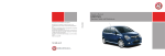
Owner’s Manual
ZAFIRA
Operation, Safety and Maintenance
Reproduction or translation, in whole or in parts,
is not permitted without prior written consent from
Vauxhall Motors Ltd.
All rights as understood under the copyright laws are explicitly
reserved by Vauxhall Motors Ltd.
All information, illustrations and specifications contained in this
manual are based on the latest production information
available at the time of publication.
The right is reserved to make changes at any time without
notice.
Edition: January 2007.
TS 1639-B-07
ZAFIRA
©Copyright by Vauxhall Motors Ltd., England.
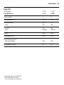
Data specific to your vehicle
Please enter your vehicle’s d ata here to keep it ea sily acc essible. This inform ation is available under the section " Technical data" as well as
on the identifica tion plate and in the Service Book let.
Fuel
De signation
Engine oil
Grade
Viscosity
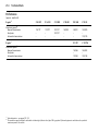
Tyre pressure
Tyre size
with up to 3 pe ople
with full load
Summer tyres
Front
Rear
Front
Rear
Winter tyres
Front
Rear
Front
Rear
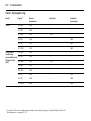
Weights
Pe rmissible Gross Vehicle
Weight
–
EC ke rbweight
=
L oading
Your Zafira
is an intelligent c om bina tion of forwardlooking technology, impressiv e safety ,
env ironmenta l friendliness a nd economy.
It now lies with you to drive your vehicle
safely and ensure that it perform s
perfectly. This O wner’s Manual provides
you with all the necessary information to
that end.
Make sure y our pa ssengers a re awa re
of the p ossible risk of accid ent and injury
which may result from im proper use of the
vehic le.
You m ust alway s comply w ith the sp ecific
laws of the c ountry that y ou are travelling
through. These laws ma y differ from the
inform ation in this Ow ner’s Manual.
When this Manual refers to a workshop
visit, we recommend your Vauxhall
Authorised Repairer.
All Vauxhall Authorised Repairers provide
first-class serv ice at reasona ble prices.
You will rec eive quick, reliable and
indiv idua l service.
Exp erienced mechanics, trained by
Vauxhall, work according to specific
Vauxhall instructions.
The O wner’s Ma nual should alwa ys be kept
in the vehic le: R eady to hand in the g lov e
compartment.
Make use of the Owner’s
Manual:
z The "In Brief" section will give you an
initial overv iew.
z The table of c ontents at the beginning of
the ow ner’s manual and within the
individual chapters will show y ou where
every thing is.
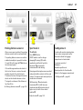
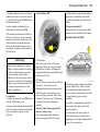
This symbol signifies:
6 continue reading on next page.
3 The asterisk signifies equipment not
fitted to all v ehicles (model variants,
engine op tions, models specific to one
country, optional equipment, Genuine
Vauxhall Parts and Acc essories).
9 Warn ing
Text marked 9 Warning provides
information on risk of accident or injury.
Disregard of the instructions may lead
to injuries or endanger life. Inform your
passeng ers accordingly.
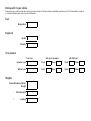
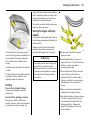
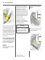
Y ellow arrows in the illustrations serve as
points of reference or indicate some action
to be performed.
Black arrows in the illustrations indicate a
reaction or a second action to be
performed.
z Its index will help you find what you
want.
Direc tional da ta, e.g. left or right, or front
or back, in the descriptions alway s relate to
the direction of travel.
z It w ill fa miliarize y ou with the
sophisticated technology.
We wish y ou many hours of p leasurab le
driving
z It w ill increase y our pleasure in your
vehicle.
z It w ill help you to handle your vehic le
expertly .
The O wner’s Manual is designed to be
clearly laid-out and easily understood.
Your V auxhall Team
Contents
Commitment to customer
satisfaction:
Our ai m: to k eep you happy with your
vehicle. All Vauxhall Authorised Repairers
offer first-class serv ice a t competitiv e
prices. Experienced, factory-trained
technicians w ork according to factory
instructions. Y our Authorised Repa irer can
supply you with GEN UINE VAU XHALLAPPRO VED PARTS , which hav e und ergone
stringent quality and precision chec ks, and
of course useful and a ttrac tiv e
VAUXHALL-APPROVED AC CESSO RIES.
Our nam e i s your guara ntee!
For d eta ils of the
Va uxhall Authorised Rep airer Netw ork,
please r ing this number; 0845 090 2044
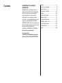
In Brief .. ..... .... ..... .... .... ..... .... ..... .... ..... .... .... . 2
Locks, Doors, Windows .. .... ..... .... ..... .... .. 30
S eats, Interior ..... .... .... ..... .... ..... .... ..... .... .. 49
Instrum ents, Controls ..... .... ..... .... ..... .... .. 82
Lighting ..... .... ..... .... .... ..... .... ..... .... ..... .... 105
Infotainment S ystem . ..... .... ..... .... ..... .... 112
C lim ate C ontrol . .... .... ..... .... ..... .... ..... .... 114
Driving and Operation ... .... ..... .... ..... .... 131
S elf-help, Vehicle C are ... .... ..... .... ..... .... 170
S ervice, Maintenance ..... .... ..... .... ..... .... 198
Technical Data .. .... .... ..... .... ..... .... ..... .... 210
Index . .... ..... .... ..... .... .... ..... .... ..... .... ..... .... 230
2
In Brief
In Brief
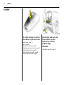
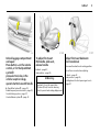
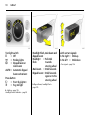
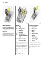
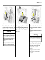
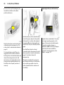
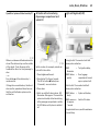
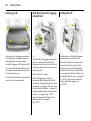
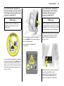
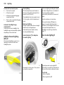
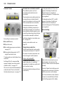
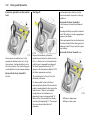
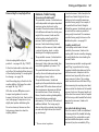
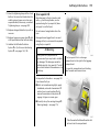
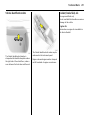
To unlock and open the vehicle:
Press button q , pull door handle
6 Door locks – p age 30,
Keys – pag e 30,
Elec tronic imm obiliser – pa ge 30,
Radio frequency rem ote control – page 32,
Central lock ing sy stem – p age 37,
Anti-theft locking system 3 – page 38,
Vauxhall a la rm system 3 – p age 42.
Unlock vehicle and open with
the Open&Start system 3:
Electronic key in vehicle
reception range,
Pull handle
6 Open&S tart system 3 – pa ge 33.
In Brief
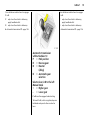
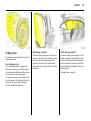
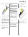
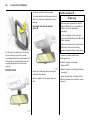
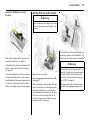
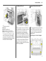
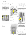
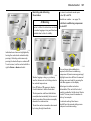
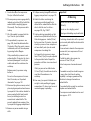
Unlock luggage compartment
and open:
Press button q on the remote
control, or for the Open&Start
system 3
place electronic key in the
vehicle reception range,
operate button beneath handle
6 Open&S tart sy stem 3 – pag e 33,
Radio frequency remote control – pag e 32,
Central locking system – page 37,
Vauxhall alarm system 3 – page 42.
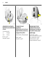
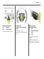
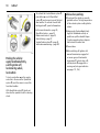
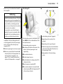
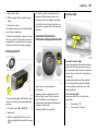
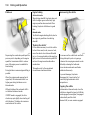
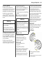
To adjust front seat:
Pull handle, slide seat,
release handle
Adjust front seat backrests:
Turn handwheel
6 Seats – pa ge 49,
Sea t position – p age 50.
Do not lea n on seat when a djusting.
9 Warning
Imp ortant: Do not sit nea rer than
10 inches (25 cm) from the steering
wheel, to perm it safe airba g deploy ment.
3
Move seat bac krest to suit sea ting position.
6 Seats – page 49,
S eat position – page 50,
Folding down the front passenger’s seat –
pag e 57.
4
In Brief
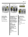
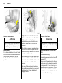
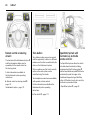
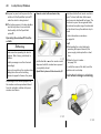
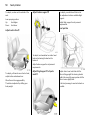
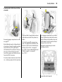
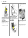
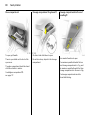
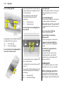
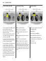
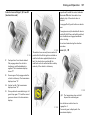
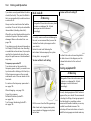
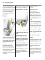
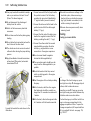
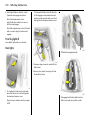
Adjusting front seat height 3:
Operate levers on outboard side
of seats
Lever pumping m otion
up:
Seat higher
To adjust front seat
inclination 3 :
Pull inner lever on front of seat,
adjust inclination, release lever,
engage seat in position
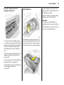
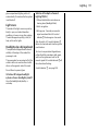
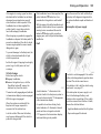
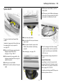
Adjusting height of head
restraints of front seat and
outboard seats in second row:
Press knob to release, adjust
height, engage
down:
Ad just inclination b y shifting body weig ht.
6 Head restraints – page 51,
Adjust rear centre head restraint and third
seat row head restraints – p age 51,
Head restraint position – page 51,
Removing the head restraint – page 52.
Seat lower
6 Seats – page 49,
Seat position – page 50.
6 Seats – pa ge 49,
Sea t position – p age 50.
In Brief
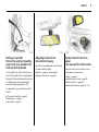
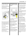
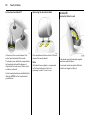
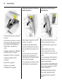
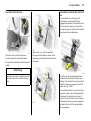
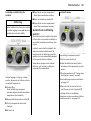
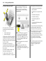
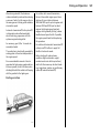
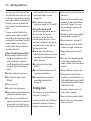
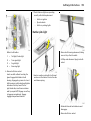
Putting on seat belt:
Pull out the seat belt smoothly,
pass it over your shoulder and
click into the belt buckle
Adjusting interior mirror:
Swivel mirror housing
The seat belt must not be twisted a t any
point. The la p belt must lie snugly against
the body. The front sea t back rests must not
be tilted b ack too far (recom mended
max imum tilting angle approx. 25°).
6 Mirrors – page 46, automatically
dipping interior mirror – p age 46.
To release belt, press red button on belt
buckle.
6 Three-point seat belt – page 63,
Airbag system – pa ge 69,
Seat position – page 50.
Swivel lever on underside of mirror housing
to reduce dazzle at night.
5
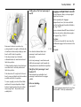
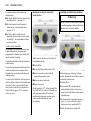
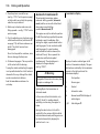
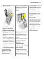
Electrical exterior mirrors 3,
adjust:
Four-way switch in driver’s door
Push right or left mirror switch: four-way
switch adjusts relevant m irror.
6 Mirrors – page 45,
Aspherical exterior m irror – page 45,
Fold ex terior mirror – p age 45,
Heated ex terior mirrors – pages13, 116.
6
In Brief
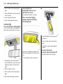
In Brief
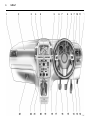
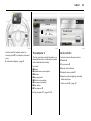
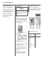
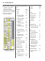
1
Page
Side air v ents ... ..... .... ..... .... .... ..... .... 115
2
Front pa ssenger’s airbag . .... ..... .... . 69
3
Centre air v ents .... .... ..... .... .... ..... ... 115
4
Left hea ted sea t 3 ... ..... .... .... ..... ... 116
Tyre deflation
monitoring sy stem 3 ..... .... .... ..... .... 154
Tyre pressure
monitoring sy stem 3 ..... .... .... ..... .... 155
Parking distance sensors 3 .. ..... ... 152
Haza rd warning lights .. .... .... .... 11 107
Central locking ..... .... ..... .... .... ..... .... .. 39
SPO RT mode 3 ..... .... ..... .... .... ..... .... 150
Right hea ted sea t 3 . ..... .... .... ..... ... 116
5
6
Central information display for
time, date, outside temperature,
Infotainm ent system 3,
check control 3 .... .... ..... .... .... ..... .... 101
Trip computer 3 ... .... ..... .... .... ..... 93, 98
Electronic Climate Control 3 ..... ... 125
Turn signal, headlight flash,
dipped beam, main beam ... ... 10, 105
Door-to-door lighting 3 .... .... ..... .... 108
Parking light .... ..... .... ..... .... .... ..... ... 109
Cruise control 3 .... .... ..... .... .... ..... ... 151
7
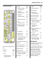
7
Pa ge
Remote control on steering
wheel 3 ... .... ..... .... ..... .... .... ..... .... ..... 112
Page
14 Accelerator pedal .... .... ..... .... . 141, 143
8
Instruments . ..... .... ..... .... .... ..... .... ..... . 82
9
Horn ... ..... .... ..... .... ..... .... .... ..... .... ..... .. 11
Driv er’s airbag .... ..... .... .... ..... .... ..... . 69
16 C lutch pedal 3 .... ..... .... ..... .... ..... .... 141
10
Windscreen wiper,
wind screen wash system,
headlight wash system 3 and
rear window w ash
sy stem ..... .... ..... .... ..... .... .... .. 11, 12, 102
11
Pa rk ing lights, dipped beam ... ..... 105
Instrument illumination ... ..... .... ..... 109
Fog tail lig ht .... .... ..... .... .... ..... .... ..... 107
Front fog lights 3 ..... .... .... ..... .... ..... 106
Head lig ht range adjustment 3 .... 107
12
Bonnet release lev er .... .... ..... .... .... 170
13
Starter switch
with immobiliser .. ..... .... .... ..... .... ..... ... 9
and
Sensor panel for emerg ency
op eration Op en&Start system 3 ... . 17
15 Brake pedal .... .... ..... .... ..... .... . 141, 157
17 S teering w heel a djustment . ..... .... .... . 9
18 S ta rt/Stop button 3 .... ..... .... ..... 17, 33
19 Ashtray s 3 .. .... .... ..... .... ..... .... ..... .... ... 79
20 S elec tor lever, manual
transmission ... .... ..... .... ..... .... ..... .... .. 14
Easy tronic 3 ... .... ..... .... ..... .... ..... .... .. 14
Automatic transmission 3 .. ..... 14, 15
21
C limate control . ..... .... ..... .... ..... .... 114
22 Infotainment system 3 ..... .... ..... .... 112
23 Glove compartment ... ..... .... ... 80, 117
8
In Brief
Control indicators
O pen&S tart system 3,
0
IDS+
fault ,
see pages 35, 83.
I
R
v
Eng ine oi l pressure,
see page 83.
Brak e system , clut ch system 3,
see pages 84, 158, 205.
Airb ag systems,
belt t ensioners,
see pages 64, 73, 84.
v
Elec tronic St abili ty Progra mme
(ESP® P lu s) 3,
see pages 84, 148.
X
Seat bel t 3,
see pages 63, 84.
Q
Door open,
see page 84.
p
Alternat or,
see page 84.
W
Coola nt temperat ure,
see pages 84, 204.
A
Eng ine electr oni cs,
tra nsm ission electronic s 3,
im mobili ser,
diesel fuel filter 3,
fault ,
see pages 30, 85, 135, 140, 147.
j
Easytronic 3, start eng ine,
see pages 85, 131.
Interacti ve Dynam ic Driv ing
System 3 , C ontinuous Dam ping
Control (CDC ) 3, SPOR T
mode 3,
see p ages 85, 150.
S
Engine oil l ev el 3,
see p ages 85, 202.
8
Exterior light s,
see p ages 85, 105.
r
Pa rking distance sensors 3,
see p ages 85, 152.
O
Turn sig nal lig ht s,
see p ages 10, 85, 106.
Y
Fuel level,
see p ages 86, 88, 144.
>
Front fog lights 3 ,
see p ages 86, 106.
C
Main beam ,
see p ages 10, 86, 105.
r
Fog t ail li ght,
see p ages 86, 107.
T
Wi nt er program me of
automa tic tra nsm issi on 3 or
Easytronic 3 ,
see p ages 86, 133, 139.
1
SPORT m ode of automa tic
transmission 3 or Easyt ronic 3,
see p ages 86, 133, 138.
y
Seat occupancy recogniti on 3,
see pages 74, 86.
Z
Exhaust emi ssion 3 ,
see pages 86, 147.
u
Anti -lock Bra ke Syst em (A BS ),
see pages 86, 159.
!
Prehea ting system 3,
Diesel parti cle filter 3,
see page 86.
w
Deflati on Detecti on System 3,
Tyre Pressur e Moni toring
System 3,
see pages 87, 154, 155.
B
Ad aptiv e Forwa rd Lighting
(AFL) 3,
fault ,
see pages 87, 108.
m
C ruise cont rol 3,
see pages 87, 151.
In Brief
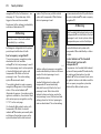
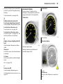
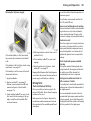
Steering column lock and
ignition:
Turn key to position 1.
To release lock, rotate steering
wheel a little
Positions:
0 = Ignition off,
1 = Steering released, ig nition off
2 = Ignition on,
Diesel engines: preheating
3 = Starting
6 Start – p age 16,
Electronic immobiliser – page 30,
Parking the vehicle – pa ge 18.
Steering column lock and
ignition on vehicles with
Open&Start system 3:
Ensure electronic key is in the
vehicle interior reception
area and press the Start/Stop
button
Release steering column lock by
moving steering wheel slightly
To start the vehicle, also operate brake or
clutch p edal.
To lock the steering wheel, switch ignition
off by pressing the Start/S top button, open
driver’s door and engage steering w heel.
Do not a llow vehicle to move whilst doing
this.
6 Start – page 17,
Elec tronic imm obiliser – pa ge 30,
Pa rk ing the vehicle – page 18.
9
Steering wheel adjustment:
Swivel lever down,
adjust height and distance,
swivel lever up,
engage
Do not a djust steering wheel unless vehicle
is sta tionary and steering c olumn lock has
been released .
6 Airb ag system – page 69.
10
In Brief
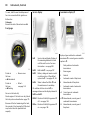
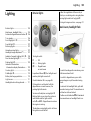
Turn light switch:
7
= Off
8
= Parking lights
9
= Dipped beam or
main beam
AUTO = Automatic dipped
beam activation 3
Press button:
>
= Front fog lights 3
r
= Fog tail light
6 Lighting – p age 105,
Headlight control indicator – page18.
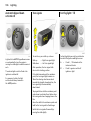
Headlight flash, main beam and
dipped beam:
Headlight
= Pull stalk
flash
towards
steering wheel
Main beam = Stalk forwards
Dipped beam = Stalk forwards
again or to the
steering wheel
6 Dipped beam, headlight flash –
page 105.
Switch on turn signals:
To the right = Stalk up
To the left = Stalk down
6 Turn signals – pag e 106.
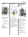
In Brief
Hazard warning lights:
On
= Press ¨
Off = Press ¨ again
Activate horn:
j Press in centre of steering
wheel
6 Hazard w arning lights – p age 107.
6 Airbag system – pa ge 69,
Remote control on the steering wheel 3 –
page 112.
Windscreen wiper:
Move stalk up gently
§ = Off
$ = timed interval wipe
% = Slow
& = Fast
Press stalk down from position § :
S ingle swipe.
6 Windscreen wiper – pag e 102,
Adjusta ble wip e interv al 3 – page 103,
Further information – pages 197, 206.
11
12
In Brief
Automatic wiping with rain
sensor 3 :
Move stalk up gently
$ = Automatic wiping with
rain sensor
§ = Off
6 Windscreen wiper – page 102,
Further information – pages 197, 206.
Operating windscreen and
headlight wash systems 3:
Pull stalk towards steering
wheel
6 Windscreen wa sh system and headlight
wash system – p age103,
Further inform ation – pages 197, 207.
Activate rear window wiper and
wash system:
Wiper on = Stalk forwards
Wiper off = Stalk forwards
again
Washing = Push the stalk
forwards and
then hold
6 Rear window wiper and wash sy stem –
pag e 104,
Further information– p ages 197, 206.
In Brief
Heated rear window,
heated exterior mirrors:
On = Press Ü
Off = Press Ü again
6 Climate control – page 114,
heated rear window – page 116.
Clearing fogged or icy windows:
Air distribution on l ,
Rotary knob for temperature
and air volume to the right;
Air conditioning system 3:
Button n must also be pushed;
Automatic air conditioning
system 3:
Press buttons n and V ,
Move rotary knob for
temperature to the right,
air quantity to A;
Electronic Climate Control
(ECC) 3:
Press button V
6 Electronic Climate C ontrol (EC C) 3 –
page 114.
13
Set automatic mode of
Electronic Climate Control
(ECC) 3:
Press AUTO button,
select temperature with rotary
knob,
open air vents
6 Electronic C limate Control (ECC ) 3 –
see page 125.
14
In Brief
Manual transmission:
Reverse: with the vehicle stationary, w ait
3 seconds after declutching and then pull
up the button on the selector lever a nd
enga ge the gea r.
If the gear does not engag e, set the lever in
neutral, release the clutch pedal and
depress again; then repeat gear selection.
Easytronic 3:
N
= Idling
o
= Driving position
+
= Higher gear
= Lower gear
A/M = Switch between
Automatic and Manual
mode
R
= Reverse gear (with
selector lever lock)
Automatic transmission 3:
P
= Park position
R
= Reverse gear
N
= Neutral
(idling)
D
= Automatic gear
selection
3
= 1st to 3rd gear
2
= 1st and 2nd gear
1
= 1st gear
The selector lever must alway s be mov ed in
the appropriate direction as far as it will
go. Upon release, it autom atically returns
to the centre position. Pay heed to the
gear/mode ind icator in the transm ission
display .
P or N must be engaged when starting.
The footb rake must b e depressed when
starting.
6 Ea sy tronic 3 – pag e 131.
To leav e P or N, switch on ignition, d epress
footbrake and press button on selector
lever.
In Brief
15
Press button on selector lever to eng age
P or R.
Press button on selector lev er to engage
P or R.
P
P
R
only when the vehicle is stationary,
apply handb ra ke first
only when the vehicle is stationary
R
only when the vehicle is sta tionary,
apply hand brake first
only when the vehicle is sta tionary
6 Automatic tra nsmission 3 – pag e 136.
6 Automatic transmission 3 – page 136.
Automatic transmission
with ActiveSelect 3:
P
= Park position
R
= Reverse gear
N
= Neutral
(idling)
D
= Automatic gear
selection
Selector lever in D to the left:
Manual mode
+
= Higher gear
= Lower gear
P or N must be engag ed w hen starting.
To leave P or N, switch on ignition, depress
footbrake and p ress b utton on selector
lever.
16
In Brief
Before starting-off, check:
To switch on the ignition, only turn the key
to 2.
z Ty re pressure and tyre cond ition –
see pa ges 159, 220.
6 Electronic im mobiliser – pa ge 30,
Diesel fuel system – page 203.
z Engine oil level and fluid levels in engine
com partment – see pages 202 to 207.
z All windows, mirrors, exterior lighting
and num ber p la tes are free from dirt,
snow and ice and are operational.
z No ob jects are placed in front of the rear
wind ow, on the instrument panel or in
the area in which the airbag s inflate.
z Seats, seat belts and mirrors are
correctly ad justed.
z Bra ke op eration.
Start engine:
Operate clutch and brake,
automatic transmission 3
to P or N,
Easytronic 3: operate brake,
do not accelerate,
Petrol engine: turn key to 3;
Diesel engine: turn key to 2,
when control indicator ! goes
off1) , turn key to 3;
Release key when engine is
running
Before restarting or switching off
the engine, turn key back to 0.
1)
Prehea ting system only switches o n at low
ou tsid e temp era tures.
In Brief
17
To switch on the ignition, d o not p ress the
brake or clutc h pedal and only press the
button briefly .
Do not start unless vehicle is stationary.
6 O pen&Start system 3 – page 33,
Elec tronic imm obiliser – pa ge 30,
Diesel fuel system – p age 203.
Start engine,
Open&Start system 3 :
Electronic key must be within
reception range of the interior,
Operate clutch or brake,
Automatic transmission 3 in P or
N, Easytronic 3: Operate brake,
do not accelerate,
Petrol engine: Press button;
Diesel engine: Briefly press
button, when control
indicator ! goes off1) , press
button again for 1 second;
release button when engine is
running
Press button ag ain to repeat the starting
proced ure or switch off the engine.
1)
Preh ea ting system on ly sw itch es on a t low
outsid e tem peratures.
Release handbrake:
Raise handle slightly, press
release button, lower handle all
the way
6 Handbrake – page 158.
18
In Brief
Parking the vehicle:
apply handbrake firmly,
switch ignition off,
lock steering wheel,
lock vehicle
To lock, press button p on the remote
control or in the case of the O pen&Start
system 3, touch the sensor in one of the
front door handles.
With Open&S tart sy stem 3 , the d riv er’s
door must be opened to lock the steering
wheel.
To activate the Vauxhall alarm system 3,
press button p or with O pen&Start
sy stem 3, touch sensor in one of the front
door ha ndles. To activate the a nti-theft
lock ing sy stem 3 , press button p twice.
Advice when parking:
6 For more information – pa ge 30,
Open&S tart sy stem – page 33,
Radio rem ote control – pag e 32,
Central lock ing – page 37,
Vauxhall a la rm system 3 – p age 42,
Vehicle decommissioning – page 209.
z Alw ays apply the handbrake firmly.
Apply the hand brake as firm ly as
possible on uphill or downhill slop es.
To reduce operating forces, depress
foot b ra ke at the same time.
z Do not park the vehicle on an ea sily
ignitab le surfa ce. The high tem perature
of the exhaust system could ignite the
surface.
z Close window.
z Before switching off ignition: with
manual transmission, engage first
or reverse gear; with automatic
tra nsmission 3 , selec tor lever in P;
with Easytronic 3 engage first or
reverse gear (note gear indicator –
see pages 131, 136).
In Brief
19
z In vehicles with automa tic
transmission 3 the key can only be
removed with the selector lever in
position P. With the O pen&Start
system 3 " P" flashes in the transm ission
display for severa l seconds if P ha s not
been selected or the handbrake has not
been applied .
That was the most important
information in brief for your first
drive in your vehicle.
z On vehicles with Ea sytronic 3 control
indica tor R flashes for a few seconds
after the ig nition is switched off if the
handb ra ke has not been app lied –
see pa ge 84.
The other pages of this chapter
contain a summary of the
noteworthy functions of your
vehicle.
z With the Open&S tart sy stem 3 the
engine ca n only be switched off when
the vehic le is sta tionary.
z Turn steering wheel until lock is felt to
engage (anti-theft protection),
removing ignition key beforehand.
With O pen&Start system 3 switch off
ig nition and open driver’ s door.
z The engine cooling fa ns ma y run after
the engine has been sw itched off –
see pa ge 201.
6 Further inform ation –
see pa ges 207, 209.
The remaining chapters of the
Owner’s Manual contain
important information on
operation, safety and
maintenance as well as a
complete index.
20
In Brief
Seats in second row
9 Warning
When the row of seats or the backrests
are being adjusted, keep hands away
from the hinge a rea - risk of injury.
Moving seats
Push release handle on right or left hand
side of sea t bench forwards a nd mov e seat
row forwards or backw ards. Release
handle and allow seat row to loc k into
position.
Adjust backres ts of outboard s eats
Push down release lever on outboard side
of backrest, b ackrest angle can be
adjusted in two places tow ards the rea r.
Release handle and latch back rest into
position.
The backrest engages in sev eral positions.
The seat m ust not be occupied whilst the
vehicle is m oving if the seat is in the vertica l
position or tilted forwards.
The outboard seat b ackrests can be tilted
forwards until they are fla t in order to make
it easier to enter and exit the vehicle. Push
relea se lev er down and tilt backrest
forward.
To move the back rest upright or chang e
the position, push release lever down and
adjust ba ckrest. Release ha nd le and
engage back rest.
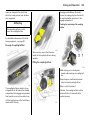
Seats in third row
9 Warning
When the seats are being moved upright
or folded in, keep hands away from hinge
area - risk of injury.
Move se ats upright out of vehicle
floor
Remove floor c ov ering 3.
Removing luggag e c om partment cover 3 –
see page 57.
Before moving the seats upright, slide seat
bench of second row of seats forwards by
pushing forward the lever a t the right or
left-hand side of the seat b ench. The tip of
the arrow at the seat bench m ust be in
front of the square m ark. S lide front seats
forwards a little if necessary.
In Brief
The sea t belts must be routed through the
belt holder a s shown in the illustration. The
latch plates must be inserted in the holder.
9 Warning
In the version with Flex Organizer 3 – see
page 60, the belts must be suspended in
the right and left seat belt ey es on the
floor of the vehicle without twisting – see
illustra tion ab ov e a nd page 67, Fig.
17420 T.
All com ponents must be removed from
the rails 3 in the lugg age compartment.
From lug gage compartm ent, use one hand
to lift seat by the handle, sw iv el ba ck and
move upright until it a ud ib ly engag es. Use
other ha nd to support top of backrest, see
Fig. 17372 T.
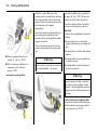
21
Lift up cover in floor between the seats and
swivel b elt buckles upwards – see pag e 22,
Fig. 17374 T.
Remove latch plate and seat b elt from seat
belt hold er.
9 Warning
The belt must not b e routed through the
belt holder when the seat belt is being
worn.
Move seat bench in sec ond row of seats to
required position a nd engage by pushing
lever on right or left-hand side of seat
bench forwa rd s – see page 20,
Fig. 17367 T.
Fit luggage compartment cover 3 by
fitting behind the third row of seats –
see page 57.
22
In Brief
Fold se ats into floor of vehicle
Removing luggage com partment c ov er 3 –
see page 57.
Before folding in the seat, slide seat bench
in second row of seats forwards by pushing
forward lever on right or left-hand side of
seat b ench – see pa ge 20, Fig. 17369 T.
The tip of the arrow on the seat bench m ust
be in front of the sq uare mark . Slide front
seats forwards a little if necessary.
Push down head restraints of seats in third
row – releasing spring catches by pressing.
Guide seat belts through belt holder as
shown in illustration and insert latch p lates
into holder.
From lugga ge com partment, press button
at top of seat backrest and swiv el backrest
forward. Raise seat by handle at rear and
swiv el bac krest further forwa rd s until seat
is lowered into v ehicle floor.
Hold seat by handle during the entire
swiv elling proced ure.
Push b elt buckles into recess in floor a nd
close c ov er.
Move seat bench in sec ond row of seats to
required position a nd engage by pushing
lever on right or left-hand side of seat
bench forwa rd s – see page 20,
Fig. 17367 T.
Fit luggage compartment cover 3 behind
second row of seats – see page 57.
Insert floor cover 3.
The components of the rails 3 and the
Flex Organizer 3 – see page 60, m ust only
be used with the seats in the third row of
seats folded in and the seat belts
unhooked – see page 67, Fig. 17420 T.
Attach released belt hooks to magnets of
brack et – see page 67, Fig. 17399 T.
In Brief
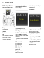
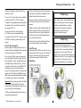
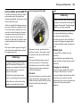
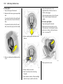
Airbag system
The airbag sy stem consists of a number of
individual systems.
Front airbag system
The front airbag system is trig gered in
the event of a serious a ccident involving
a frontal im pact and forms safety c ushions
for the driver and front passenger.
The forward movem ent of the d riv er and
front passenger is check ed a nd the risk of
injuries to the upper body a nd head
thereby substantially reduced.
Side airbag system 3
The sid e airbag is triggered in the event of
a side-on c ollision to form a safety cushion
for the driver or front passenger in the
respective door area. This substantially
reduces the risk of injury to the upp er body
and pelv is.
Curtain airbag sys te m 3
23
The curtain a irba g system triggers in case
of a side-on collision and provid es a safety
barrier in the hea d area on the respective
side of the vehic le. This reduces the risk of
injury to the hea d considerab ly in case of a
side-on collision.
6 Airb ag system – page 69.
24
In Brief
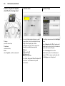
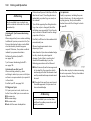
Active head restraints 3 on front
seats
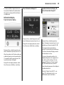
Operating menus in the
information display 3
In the event of a rear-end impa ct, the
active head restraints tilt forwards slightly.
The head is more effectiv ely supported by
the head restraint and the risk of injuries
caused by whiplash in the neck area is
red uced.
Menu options are selected via menus
and using the arrow buttons or the
multi-function knob of the Infotainment
sy stem 3 or the buttons 3 on the steering
wheel. The respective menu options are
shown on the d isplay .
Active head restraints are id entified by the
lettering ACTIVE on the head restraint
guide sleev es.
Selection using the arrow buttons 3: Press
the arrow buttons to the left or right.
6 Head restra ints – page 51.
S elec tion using multi-function knob 3:
rotate and press multi-function knob.
To exit a m enu, turn the m ulti-func tion
knob left or right to Return or Mai n and
select.
In Brief
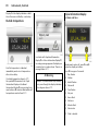
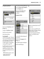
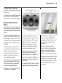
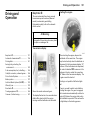
Ü Board Computer
BC 1
BC 2
Timer
1
257.0
Ø 40
8
7.0
Ø 31.0
Tyres
Selection with left adjuster wheel on
steering wheel 3: turn adjuster wheel and
press.
6 Information display – page 89
19,5° 19:36
All values
miles
Coolant level
mph
ch eck
gals
mpg
OK
Trip computer 3
Check control 3
The trip computers provide information on
driving data, which is continually recorded
and ev alua ted electronically.
The check control softwa re monitors
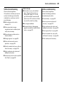
Functions:
z Range
z Instanta neous consum ption
z Distanc e
z Average speed
z Effective consumption
z Average consumption
z Stop watch
z Tyre pressure 3
6 Trip comp uter 3 – pages 93, 98.
z Fluid levels
z Tyre pressure 3
z Remote control battery
z Vauxhall alarm system 3
z Important ex terior lighting , including
cables and fuses.
6 Check control 3 – page 101.
25
26
In Brief
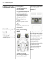
Remote control on steering
wheel 3
The functions of the Infotainm ent system 3
and the information display can be
opera ted with the remote control on
the steering wheel.
Further information is available in
the I nfotainment system operating
instructions.
6 Remote control on steering wheel 3 –
page 112,
Infotainm ent system – page 113.
Twin Audio 3
Tw in Audio p rov id es rear seat occupants
with the opportunity to listen to a different
audio source tha n the one selected by the
driver on the Infotainment sy stem.
Only a n audio source tha t is not currently
active on the radio system can be
controlled using Twin Audio.
Tw o headp hone connections are a vailable,
with separate volum e c ontrols.
Further inform ation is av ailable in the
Infotainment sy stem opera ting
instructions.
6 Twin Audio 3 – page 112.
Open&Start system with
electronic key and radio
remote control 3
The Open&S tart sy stem allows the vehicle
to be locked and unlocked, including
mechanical anti-theft locking system 3
and the Vauxhall a la rm system 3 without a
mechanical key and the engine to be
started and stopped using a S ta rt/Stop
button. All the d riv er has to do is carry the
electronic key around with him.
6 Open&S tart system 3 – pa ge 33.
In Brief
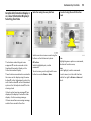
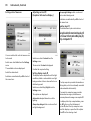
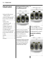
Parking distance sensors 3
Sport mode 3
FlexOrganizer 3
When rev erse gear is selected, the pa rk ing
distance sensors switch on automatically.
To activate
The p arking dista nce sensors ca n also be
enab led m anually at a speed of less than
15 mph (25 k m/h) using the r button on
the instrum ent panel.
SPORT mode is used to cha ng e
damping 3 , steering 3, throttle
application and the shift point for
Easytronic 3 and autom atic
tra nsmission 3 whilst driving.
The side walls contain retaining strips,
where va rious components can be
attached to divide the lugg age
compa rtm ent or fasten loads.
If the vehicle approaches a n ob stacle at
the front or the rear, a series of acoustic
signa ls is hea rd in the v ehicle interior.
The interv al between the signals becomes
shorter as the obstacle becomes closer.
The signal is continuous if the distance is
less than 30 cm .
6 Park ing distance sensors 3 – page 152.
Press S PO RT button.
Damping and steering become more direct
and provide better contact with the road
surface. The engine reacts more quickly to
accelerator movements.
With Easy tronic 3 and automatic
tra nsmission 3, the shift tim es are
shortened and shifting tak es place at
higher revs (not with cruise control
enabled 3).
6 Sp ort m ode 3 – p age 150.
The sy stem consists of
z adapters
z variable partition net
z mesh pockets for the sid e wa lls
z hooks in the lug gage compartment
6 FlexO rg aniz er 3 – pag e 60.
27
28
In Brief
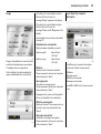
Ü Board Computer
BC 1
BC 2
Timer
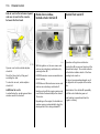
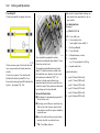
Tyres
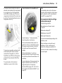
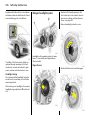
Tyre pressure loss monitoring
system (DDS = Deflation
Detection System) 3
The Deflation Detection S ystem
continuously monitors the speed of all
wheels whilst driving. If a ty re loses
pressure, it becom es sm aller and therefore
rotates m ore quic kly than the other wheels.
If the system detects a difference in speed,
the c ontrol indicator w illuminates in red.
After a tyre pressure correc tion or after a
tyre or w heel cha nge, the system m ust be
initialised by pressing the DDS button.
6 Tyre p ressure loss monitoring sy stem 3 –
page 154.
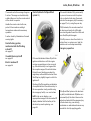
Tyre Pressure Monitoring
System 3
The Ty re Pressure Monitoring System
continually checks the pressure and speed
of all four wheels whilst driving.
A pressure sensor is insta lled in ea ch wheel.
The inflation pressures of the individual
wheels are tra nsmitted to a controller,
where they are compared.
The current tyre pressures ca n be
displayed on the Gra phic al Inform ation
Display or the Colour Inform ation
Display 3.
Deviating tyre pressures are displayed in
the form of messages on the information
display whilst driving.
6 Tyre Pressure Monitoring System 3 –
pag e 155.
In Brief
29
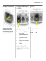
Motorway lighting
At higher speeds and continuous straight
ahead travel, the dipped bea m
automatically raises slightly, thereby
increa sing hea dlight rang e.
Adaptiv e Forward Lighting 3 – page 108.
Adaptive Forward Lighting
(AFL) 3
AFL im prov es lighting in curv es (curve
lighting ) on vehicles with Bi-Xenon
head lig ht system .
Curve lighting
The Xenon light bea m pivots based on
steering wheel position a nd speed
(from a pprox. 6 m ph (10 km /h)).
30
Lo cks, Doo rs, Windows
Locks, Doors,
Windows
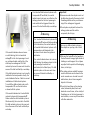
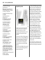
Replacement keys
The key number is specified in the vehic le
docum ents and in the C ar Pass 3.
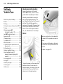
Key with foldaway key section 3
The key is a c onstituent of the electronic
immobiliser. Ordering keys from a Vauxhall
Authorised Repairer g uarantees problem free op eration of the electronic
immobiliser.
Replacem ent keys ... ..... .... ..... .... .... ..... .
Loc k cylinders . ..... .... ..... .... ..... .... .... ..... .
Ca r Pass... .... .... ..... .... ..... .... ..... .... .... ..... .
Key with foldaw ay key section 3 . ..... .
Electronic immobiliser... .... ..... .... .... ..... .
Store personal vehicle settings in the
vehicle key 3 ..... .... ..... .... ..... .... .... ..... .
Radio frequency remote control 3
with mec hanical key .. .... ..... .... .... ..... .
O pen&Start system 3 ... .... ..... .... .... ..... .
Central locking system . .... ..... .... .... ..... .
Fault when locking or unlocking... ..... .
Lug gage compartment .... ..... .... .... ..... .
Vauxhall alarm system 3. ..... .... .... ..... .
Child safety locks . .... ..... .... ..... .... .... ..... .
Ex terior mirrors..... .... ..... .... ..... .... .... ..... .
Interior mirror .. ..... .... ..... .... ..... .... .... ..... .
Electric windows 3 ... ..... .... ..... .... .... ..... .
Sunblind on panoramic roof 3 . .... ..... .
30
30
30
30
30
31
32
33
37
40
41
42
45
45
46
46
48
When electronic k eys of the Open&S tart
sy stem are being replaced , all keys must be
ha nded to the dea ler for programming.
Keep the sp are k ey in a safe plac e.
Locks – see page 197,
Open&S tart sy stem, elec tronic keys –
see p age 33.
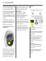
Loc k cylinders
Designed to free-wheel if they are
forcefully rotated without the correct k ey or
if the correct key is not fully inserted.
To reset, turn cy linder with the c orrect key
until its slot is vertica l, remove key and then
re-insert it. If the cylinder still free-wheels,
turn the key through 180° and rep eat
op eration.
Car Pass
The Ca r Pass contains a ll of the vehicle’s
data and should therefore not be k ept in
the vehicle.
Have your Ca r Pa ss to hand when
consulting a Vaux hall Authorised Repairer.
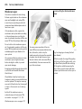
Press button to extend. Press button to
retrac t and key sec tion engages audibly .
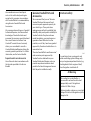
Electronic immobiliser
Locks, D oors, Windo ws
The system check s w hether the vehicle is
allowed to be started with the mechanical
key or electronic key of the Open&Start
system 3 that is being used. If the key is
recognised a s "a uthorised" the vehicle can
be started. The checking tak es place via a
transponder in the k ey.
Control indicator for immobiliser A
31
Note
The immobiliser does not lock the doors.
Therefore, after leaving the v ehicle a lways
lock it and switch on the Vaux hall alarm
system 3 – see p ages 38, 42.
Store personal vehicle settings
in the vehicle key 3
The last settings selected
z for the Electronic Climate Control
(ECC ) 3
z information display 3
z Infotainment sy stem 3
z instrument illumination
The electronic imm ob iliser activates itself
automatically after the key has been
rem ov ed from the ignition or, with the
O pen&Start system 3, w hen the engine is
switched off by pressing the Start/Stop
button.
The c od e number of the electronic
immobiliser is giv en in the C ar Pass.
Control indica tor A illuminates briefly
when the ig nition is sw itched on.
are stored automatically depending on the
vehicle k ey used.
If the control indicator flashes w hen the
ignition is on, there is a fault in the sy stem;
the engine cannot be started. S witc h off
the ignition and then rep eat the start
attempt.
Different settings are stored for ea ch
vehicle k ey. Use of a vehicle key will
activa te the settings associated with it.
If the control indicator A continues
flashing, attempt to sta rt the engine using
the spare key a nd seek the assistanc e of a
work shop.
If control indicator A illuminates after the
engine is started, there is a fault in the
engine electronics or transmission
electronics 3 (see pages 135, 140, 147) or
there is water in the diesel fuel filter 3 – see
page 203.
Each tim e the vehicle is locked , the settings
are saved again.
32
Lo cks, Doo rs, Windows
Radio frequency remote
control 3 with mechanical key
Fault
If the central locking system cannot be
operated w ith the rem ote control, it may
be due to the following :
z The range of the remote control has
been ex ceeded .
z Remote control battery voltage is too
low . Battery rep la cement – see next
page.
Dep ending on the equipment level of your
vehic le, one of the remote controls shown
on this p age will be used .
Radio frequency remote control in version
with O pen&Start system 3 – see page 34.
The rem ote control is integ ra ted in the key .
Used to op erate:
z Central locking system ,
z Mechanical anti-theft locking system 3,
z Vauxhall ala rm system 3 .
The w indows of vehicles with electric
windows in all doors 3 can also be opened
or closed using the remote c ontrol – see
page 46.
The remote control has a ra nge of approx.
5 metres. This range can be affected by
outside influences. Aim the remote control
at the v ehicle to op erate.
Handle the rem ote control with care,
protect it from m oisture and high
temperatures and avoid unnecessary
op eration.
Function check by illumination of haz ard
warning lig hts.
Central locking system, mechanical
anti-the ft locking system 3
see p age 37.
Vauxhall alarm system 3
see p age 42.
Electric windows 3
see p age 46.
z Frequent, repeated operation of the
remote control outside the reception
rang e of the vehicle (e. g. too far from
vehicle, rem ote control is then no longer
recognised). Remote control
sy nchronisation – see next pa ge.
z Overloading the c entral locking by
operating at frequent intervals, the
power supply is interrupted for a short
time.
z Interferenc e from higher-power radio
waves from other sources.
To rectify the ca use of the fault, we
recommend that y ou seek the assistanc e of
a work shop.
O pen d riv er’s door with key – see page 40.
Locks, D oors, Windo ws
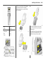
Remote control battery re placem ent
33
In the event of a malfunction or when
the battery has been replaced,
synchronis e the rem ote control
After rep lacing the battery, unlock the door
with the k ey in the lock. The remote control
will be sy nchronised when you sw itc h on
the ignition.
Open&Start system 3
The electronic k ey must b e within the
external reception range about 1 metre
from the vehicle in order to lock a nd unlock
the vehicle.
Replace the battery as soon a s the range
of the remote control begins to shrink .
Key wit h foldawa y k ey sec tion
Ex tend k ey – see page 30. Op en remote
control. Rep la ce b attery - battery type –
see pa ge 223 – noting installation position.
Close remote control.
Make sure that y ou dispose of old b atteries
in accordance with environmenta l
protection regulations.
Key wit h fixed k ey sec tion
Hav e the battery replaced by a workshop.
The O pen&Start system allows the vehic le
to be lock ed and unlocked, including the
mechanical a nti-theft locking system 3
and the Vaux hall alarm system 3 , and the
engine to b e started and stop ped without
a m echanical key . All the driver has to do is
keep the key to hand.
The windows of vehicles with electric
wind ow s in all doors 3 c an also be opened
or closed from outside using the rem ote
control of the elec tronic key – see page 40.
If the electronic key is recognized as
"a uthorised" the vehicle can b e unlocked
by pulling a door handle or by operating
the button beneath the tailgate handle
and the doors and the tailgate can b e
opened.
34
Lo cks, Doo rs, Windows
The engine and the ignition are switc hed
off by p ressing the Sta rt/Stop button a gain.
The vehic le must be sta tionary. The
immobiliser is activated at the sa me tim e.
If the ignition has been switched off and
the vehicle is stationary , the steering
colum n lock activates autom atic ally when
the driver’s door is opened or closed.
When the S tart/Stop button is pressed, the
system re-checks the authorisation. The
electronic key has to be recognised in the
interior in order to do this. After the key has
been authorised the ignition switches on.
At the same time, the electronic
immobiliser is switched off and the electromechanic al steering column lock is
deactivated . Pressing the S tart/S top button
again with the brake or clutch ped al
depressed or in P or N with automatic
transm ission 3 starts the engine. Press
button for a t least one second with the
vehic le stationa ry or hold down until the
engine sta rts.
The electronic key must be within the
reception range of the interior to turn the
ignition on or off. We recommend tha t the
driver carries the elec tronic key with him. If
the electronic key is not recognised, select
another key position.
The Op en&Start system 3 does not the lock
the vehicle automatically if the electronic
key is outside the ex ternal reception range
of approx im ately one metre from the
vehicle.
Radio frequency re mote control
Do not p ut the electronic key in the
lugg age compartment or in front of the
information display.
The vehicle can be locked and unlocked by
conventional means using the remote
control with the buttons on the electronic
key.
If the brake or clutch peda l is depressed ,
the engine ca n be started right away with
a single press on the Start/Stop button.
Releasing the S tart/Stop b utton interrupts
the starting proced ure.
doors. The electronic key m ust be within
the external reception rang e of
app rox imately one metre from the vehicle.
The vehic le is locked from the outsid e with
the doors closed by touching the sensor
panel in the door ha ndle of one of the front
In ad dition, the mechanical anti-theft
locking system and Vauxhall a larm sy stem
can b e arm ed a nd disa bled using the
remote control. The wind ow s of v ehicles
with electric windows in all doors 3 c an
also be opened or closed from outside
using the rem ote control.
Locks, D oors, Windo ws
The remote control has a range of approx.
5 metres. This ra nge can b e affected b y
outside influences. Aim the rem ote control
at the vehicle to opera te.
Control indicator for Ope n&Start
system 0
Handle the remote control with care,
protect it from moisture and high
tem peratures and avoid unnecessary
opera tion.
If this 0 c om es on when the vehicle is in
motion, there is a system error. Seek the
assistance of a workshop immediately.
Central locking system,
mechanical anti-the ft locking
system 3
Eme rgency operation
see page 37.
see page 42.
Ele ctric windows 3
see page 46.
If the control indicator 0 is perma nently
on, an error has occ urred in the system .
Lock or unlock vehicle using the remote
control or the emergency k ey if necessary –
see page 37, or try using the spare key .
If 0 illumina tes, this can also mean that
the steering column lock is still locked:
mov e steering w heel to and fro a little and
press Sta rt/Stop button again.
Function check by illumination of hazard
warning lights.
Vauxhall alarm s yste m 3
35
If the control indicator flashes 0 with the
ignition switched on or with the engine
running an opera ting error has occurred,
e.g. the electronic key is no longer w ithin
the rec eption range of the vehic le interior.
During the next starting procedure the
engine may not be a ble to be started. Press
Start/S top key slightly long er to switch the
ignition off.
Flashing of the 0 can a lso b e an indication
of com plete failure of the electronic key. In
this case operation is only possible using
the emergency facility – see nex t colum n.
InSP3 in the service display or an
appropriate m essag e in the information 3
display indicates that the battery of the
electronic k ey need s replacing – see
page 36.
If the Op en&Start system or the electronic
key fails (control indica tor 0 flashes or is
permanently on) the driver’ s d oor ca n be
locked or unloc ked with the emergency key
in the electronic k ey: press locking
mechanism on underside and remove cap
towards the front by applying g entle
36
Lo cks, Doo rs, Windows
pressure to the cap. Push emergency key
towards the outsid e over the detent
position and remove.
O nly the driv er’s door can be locked and
unlock ed using the emergency key . The
entire vehicle is unlocked as describ ed on
page 41.
The Vauxhall alarm sy stem 3 may be
triggered when the vehicle is unlocked.
Switch ignition on to dea ctivate alarm and
release the steering column lock: hold
electronic key at m arked position on the
steering column p anelling and press the
Start/Stop button. Repeat proc edure if
necessary.
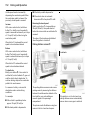
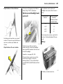
Replacing battery in electronic key
Hold electronic key at the marked loc ation
to start the engine, depress brake peda l or
clutch p edal or in v ehicles with automatic
tra nsmission 3 depress brak e pedal a nd
select P or N, Then press Start/S top button
again.
Press S tart/Stop b utton for at least
2 seconds to switch the engine off. Lock all
doors ex cep t d riv er’s door as described on
page 41. Lock driv er’s door with
emergency key .
This option is intend ed for emerg encies
only. Replace the battery in the electronic
key as quickly as p ossible or hav e the
sy stem rep aired. Seek the assistance of
a workshop.
Replace battery immediately if the system
is no long er operating properly, or the
range of the remote control deteriorates.
The need for a battery change is
indicated by I nS P3 in the S ervice Display or
in vehicles with check control 3 an
app ropriate message appears on the
display – see page 101.
Locks, D oors, Windo ws
Fault in Ope n&Start system or remote
control
If the central lock ing cannot be operated or
the engine cannot be started, the cause
may be one of the following :
37
Central locking system
For doors, boot lid /tailgate and tank flap .
To unlock:
Remot e cont rol wit h mechanical key
z Electronic key out of reception range, or
out of range of remote control,
z Remote c ontrol battery voltage is too
low. Battery rep la cement – see page 36,
z Frequent, repeated op eration of the
rem ote control outside the reception
range (e.g. too far from vehic le, remote
control is then no longer recognised),
To rep la ce the battery , press the lock ing
mechanism on the und erside of the
electronic key and remove the cover
towards the front by applying gentle
pressure – see page 35, Fig . 17037 T. Push
off cover with emblem on the button side
towards the outsid e.
z O verloading the central locking by
opera ting at frequent interv als, the
power supply is interrup ted for a short
time,
Replace battery, for battery type – see
page 223, pay a ttention to installation
position. Engage caps.
To rectify the cause of the fault, cha nge the
position of the electronic key or remote
control or rep lace the battery in the remote
control. I f the fault persists, seek the
assista nce of a w ork shop.
Radio fre quency re mote control
synchronisation
The remote control synchronises itself
automatically during every starting
proced ure.
z Interference from hig her-power rad io
wav es from other sources.
Emergency operation – see pa ge 35.
Press button q on remote control.
To open the door, p ull the handle. Open
the lugg age compartment by operating
the button beneath the tailgate handle.
38
Lo cks, Doo rs, Windows
O pen&S tart system wit h elect ronic key 3
Rem ote control w ith mechanic al key
The electronic k ey must b e outsid e of the
vehicle. All doors and the luggage
compa rtm ent are locked by touching the
sensor in the door ha nd le of the driver’s or
front passeng er’s door
– or –
Press button p of the electronic k ey’ s
remote control.
Mechanical anti-the ft locking
sys tem 3
9 Warn ing
The electronic key m ust be outside of the
vehic le. The vehicle is unlocked b y pulling a
door handle or by operating the button
beneath the ta ilga te handle.
– or –
Press button q of the elec tronic key’ s
rem ote control.
Press button p on remote control.
Open&Sta rt system w ith electronic k ey 3
Do not use the sy stem if there are people
in the vehicle! The doors cannot b e
unlocked from inside.
Remot e cont rol wit h mechanical key
To lock
Close doors, lugga ge com partment and
tank flap.
All doors must be c losed . At the la test
15 seconds after locking, p ress b utton p
of the remote control ag ain.
Locks, D oors, Windo ws
Loc k buttons on all d oors are positioned
suc h that doors cannot be opened.
If the ignition was on, the driver’ s door
must be opened and closed once so tha t
the v ehicle can be secured.
Central locking button for locking
and unlocking the doors from inside
the vehicle
39
Note
z If the driv er’s door is not closed properly ,
the central loc king sy stem will not lock.
z To loc k the d oors from within (e.g . to
prevent unw anted entry from outside),
press central locking switch m in the
centre console.
O pen&S tart system wit h elect ronic key 3
z After unlocking with the key in the lock 3
and opening the driver’ s door, the entire
vehicle is unlocked.
z If the central lock ing system is loc ked, the
doors ca n also be unlocked by p ulling
the interior handle. This unlocks the
central locking system .
Press button m in the centre console: doors
are locked or unlocked.
All doors must be c losed . The electronic key
must be outside of the vehicle. No more
than 15 seconds after locking, touch the
sensor in the handle of the driver’ s or front
passenger’s door ag ain
– or –
press button p of the electronic key ’s
rem ote control again.
If the ignition was on, the driver’ s door
must be opened and closed once so tha t
the v ehicle can be secured.
All doors are sec ured aga inst opening.
The LED in the central locking b utton m
illuminates for around 2 minutes after
lock ing with the remote control.
If the doors are loc ked from the insid e
during driv ing using the central locking
button, the LED m illum inates
permanently .
If the key is in the ignition 3, locking is only
possible if all doors a re closed.
When the mechanical anti-theft locking
sy stem 3 is a ctiv e – see page 38, the doors
cannot b e unlocked with this b utton.
z Locked doors unlock themselv es
autom atically when an accident of
a certa in severity occurs (for outside
assista nce), and the hazard warning
lights come on. In the version with a
mec hanical key , the k ey must also be in
the ignition.
z With the Open&Start system 3 the
vehicle cannot be unlocked within
2 second s of locking. Within this tim e a
door handle can be pulled or the button
beneath the tailgate handle operated to
check whether the vehicle is locked .
z The O pen&Start system 3 does not lock
the v ehicle automatically if the electronic
key is outside the recep tion range of the
vehicle (more than 1 metre away from
the vehicle).
40
Lo cks, Doo rs, Windows
z A spa re key m ust not be present in the
vehicle with the O pen&Start system 3
when the v ehicle is b eing locked.
Rem ote control w ith mechanic al key
z The locking sensors in the door ha ndles
must be kept clean for unrestricted
functionality with the O pen&S ta rt
system 3.
Further information on windows –
see page 46.
Operating the windows 3 from the
outside
Fault
9 Warning
z Overloading the c entral locking by
operating at frequent intervals, the
power supply is interrupted for a short
time,
Ta ke c are when operating the electric
wind ows. Risk of injury, particula rly to
children.
Vehicle passengers must be informed
according ly .
Keep a close watch on the windows w hen
closing them . Ensure that nothing
becomes trapped in them a s they move.
Dep ending on the v ehicle equipment 3,
the w indows ca n be opened and closed
from the outside in v ehicles with power
windows in all doors.
Hold down button q of rem ote control to
open. To close, hold d own button p or
touch sensor in door handle for longer. The
electronic key must be recognised within
the ex ternal recep tion ra ng e. It is a dvisable
for the d riv er to k eep the electronic key to
hand.
Hold button q or p on the rem ote control
depressed until a ll windows hav e opened
or completely closed.
Open&Sta rt system w ith electronic k ey 3
z Defec tiv e fuse in fusebox –
see page 184.
To rectify the ca use of the fault, seek the
assistance of a workshop.
Fault when locking or unlocking
Locks, D oors, Windo ws
O pen&Start system wi th el ect ronic k ey 3
O perating the button b enea th the tailgate
handle unlocks and op ens the luggage
compa rtm ent together with the doors if the
electronic key is recognized outside of the
car,
– or –
Press button p of the electronic k ey’ s
remote control, the luggage compartment
will be unlocked together with the doors.
Fault in remote control or O pe n&Start
system 3
To unlock
Turn key or em ergenc y key with
O pen&Start system 3 – see page 35,
forwards in d riv er’s d oor lock a s far as it will
go. Turn key back to a vertic al position and
rem ov e. The entire vehicle is unlock ed
when the driver’s door is opened. The
vehic le is unlock ed (not possible if antitheft locking system 3 enabled
beforehand ). To deactivate the anti-theft
locking system 3 switch ignition on.
Em ergency operation of the Open&Start
system 3 – see pa ge 35.
To lock
O pen front passenger’s door, close d riv er’s
door, press centra l locking button m in
centre console. Central locking system
locks all doors. Close front passenger’ s
door.
Malfunction in ce ntral locking s yste m
To unlock
Turn key or em ergenc y key with
O pen&Start system 3 – see page 35,
forwards in d riv er’s d oor lock a s far as it will
go. Turn key back to a vertic al position and
rem ov e. The other doors can b e opened b y
pulling the handle inside the d oors (not
possible if anti-theft locking system 3
enab led b eforehand). The lugg age
compartment and fuel filler cap remain
locked. To deactivate the anti-theft locking
system 3 sw itch ignition on – see page 44.
41
To open
To lock
With the Open&S tart sy stem 3 – see
page 35. To lock passenger’s door, insert
key or em ergency key into opening a bove
lock on inside of door and opera te lock b y
pressing (audible) and close d oor.
Procedure m ust be carried out for every
door. Driver’s door can be locked from the
outside. The unlocked fuel filler ca p and
the tailgate cannot be lock ed.
Emerge ncy ope ration of
Open&Start system 3,
see p age 35.
Luggage compartment
To unlock
Rem ote control w ith mechanic al key
Press button q on the rem ote control, the
lugg age compartment a nd doors a re
unlocked.
The lugg age compartment is opened b y
operating the button beneath the handle.
9 Warn ing
Do not drive with the tailgate open or
ajar, e.g. when transporting bulky objec ts,
since toxic exhaust g as could penetra te
the interior.
42
Lo cks, Doo rs, Windows
Fitting of a ccessories on the tailgate will
increase its weight. If it becomes too heavy ,
the ta ilga te will then not stay open.
Rem ote control w ith mechanic al key
To activate
Remot e cont rol wit h mechanical key
To close
Press button p on remote control.
Close lugg age com partment using handle
on the inside of the tailgate.
Do not operate the button beneath the
handle when closing. Otherw ise the
luggage compartment will once again be
unlock ed.
To lock
Close doors, lugga ge com partment and
tank flap.
Open&Sta rt system w ith electronic k ey 3
Press button p of the electronic key remote
control or touch sensor in handle of one of
the front doors. The electronic key must be
recognised in the ex ternal reception area.
It is advisable for the driver to keep the
electronic k ey to ha nd.
Vauxhall alarm system 3
The system m onitors
z the doors, luggag e com partment,
bonnet,
z the passenger compartm ent,
z vehicle tilt, e.g. if it is raised,
z the ig nition.
All doors, windows and the bonnet must b e
closed. Press remote control button p to
arm the anti-theft alarm sy stem and lock
the vehicle.
If the ig nition was sw itched on, the driver’s
door must be opened and closed once so
that the anti-theft alarm system can be
switched on.
Locks, D oors, Windo ws
O pen&S tart system wit h elect ronic key 3
All d oors, windows and the b onnet must be
closed. The electronic key must be outside
of the v ehicle. Touch the sensor in the
handle of the driver’s or front passenger’ s
door
– or –
Press button p of the elec tronic key’ s
rem ote control.
If the ignition was switched on, the driver’s
door must be opened and closed once so
that the a nti-theft ala rm system ca n be
switched on.
Activation without monitoring
of passenge r compartment and
vehicle tilt
43
Light emitting diode (L ED)
During the first 10 sec onds of anti-theft
alarm sy stem activa tion:
Switch on when, for exam ple, anim als are
to be left in the v ehicle.
1. C lose tailgate a nd bonnet.
2. Press button b in the roof console.
The LED in button m flashes (m ax.
10 second s) – see next c olumn
3. C lose doors.
4. Sw itch on a nti-theft ala rm system. LED
illuminates. After app rox . 10 seconds the
system is ac tiv ated, without m onitoring
of the passenger com partment or vehicle
tilt. LED flashes until sy stem is switched
off.
z LED
illuminates.
z LED flashes
quickly
=
Test, ignition dela y,
=
Door, luggage
compartment, bonnet
open or system fault.
After the first 10 seconds of anti-theft
alarm sy stem activa tion:
z LED flashes
=
slowly
z LED comes on =
for approx.
1 second
Sy stem switched on,
Switch off function.
If a system fault occ urs, seek the assistance
of a w ork shop.
44
Lo cks, Doo rs, Windows
To deactivate
Remote contr ol with m ec hanical k ey
Press button q on rem ote control
– or –
Switch on ignition.
O pen&S tart system wit h elect ronic key 3
The vehic le is unlock ed by pulling a door
ha ndle or by opera ting the button beneath
the tailgate handle a nd the anti-theft
alarm system is d eactivated when the
electronic k ey is recognized as being
outside of the vehic le.
– or –
Press button q of the electronic key’s
remote control.
Ala rm siren
w ith integrat ed batt ery 3
The alarm siren monitors the on-board
voltage network and triggers an ala rm if
this network is manipulated (e.g . if the
vehicle’s ba ttery is disconnected by
unauthorised persons). The alarm siren ha s
its own power supply and is therefore not
dependent on the vehicle’s battery.
In the event of a fault in the remote control
or the Op en&Start sy stem, open the vehicle
as described on page 40.
If the alarm is trigg ered when the driver’ s
door is opened, dea ctiv ate the anti-theft
alarm system by switching on the ignition.
If the vehicle’s battery is to be
disconnected (e.g. for maintenance w ork ),
the alarm siren must be dea ctivated as
follows: sw itch the ignition on then off,
disconnect the vehicle’s battery within
15 seconds.
Note
To swit ch off alarm siren:
S witc h ignition on then off.
Changes to the vehicle interior, such a s the
use of seat covers, could impair the
function of passenger comp artment
monitoring.
Alarm
While the anti-theft alarm sy stem is
switched on the alarm can be triggered,
indica ted b y:
z an acoustic sig nal (horn) and
z a v isual signal (hazard w arning lights).
The number and duration of the alarms are
legally established.
The alarm can be silenc ed b y pressing a
button on the remote control or by
switching on the ig nition. The anti-theft
alarm system is d eactivated at the same
tim e.
Locks, D oors, Windo ws
Child safety locks
45
Exterior mirrors
Swing in e xterior mirror
Ad just using the four-wa y switch in the
driver’s door. Press mirror switch to the
rig ht or left. The four-way switch w ork s on
the corresponding mirror.
Manually: the exterior m irrors can be
folded in by pressing gently on the outer
edge of the housing.
9 Warning
Use the child safety lock w henever
children are oc cup ying the rear seats.
Disreg ard may lead to injuries or
endanger life. Vehicle pa ssengers must be
informed accordingly.
The mirror glass is m ov ed in the direc tion
whic h corresp onds to the pressing of the
four-way switch.
Using key or screwdriver, turn rotary knob
at rear door lock from the vertica l p osition:
door cannot then be opened from insid e.
As pherical ex terior mirror 3
Increases the field of view. Estima ting the
distance away of vehicles following y ou is
only possible to a limited ex tent b ecause of
slight distortion.
Electrically 3: Press n and b oth mirrors will
swing in.
Press button n again - both exterior
mirrors swiv el to the starting position.
If a sw iv elled-in electric mirror ha s b een
swivelled out manually, pressing button n
only swivels the other mirror out electrically.
Pressing n again swivels both m irrors b ack
in electrically.
Fold mirrors out to driv ing position before
mov ing away.
46
Lo cks, Doo rs, Windows
To adjust, swivel the mirror housing.
To reduce d azzle from following v ehicles at
night, swiv el lever on underside of mirror
housing.
Automatic anti-daz zle interior
mirror 3
Electric windows 3
9 Warn ing
Take care when operating the electric
windows 3. Risk of injury , esp ecially for
child ren. Inform the passeng ers
accordingly.
If there are children on the rear seat,
switch on the child safety system 3 for the
electric windows.
Keep a close wa tc h on the windows when
closing them . Ensure that nothing
becom es trapped in them as they m ov e.
For the safety of pedestrians, the exterior
mirrors will swing out of their normal
mounting p osition if they are bumped with
sufficient force. Reposition the m irror by
apply ing slight pressure to the mirror
housing.
Interior mirror
The electric windows can be used
z with ignition on,
z within 5 m inutes of switching
ignition off 3,
Dazzle from following v ehicles at night is
autom atic ally reduc ed.
With the ignition off, the mirror does not
dim.
z within 5 minutes of switching ignition key
to position 1.
Function standby a fter switching off the
ignition terminates when the driver’s door
is opened.
Locks, D oors, Windo ws
For increm ental opera tion, briefly pull or
press the switch. For a utomatic opening or
closing, pull or press the sw itch longer. Pull
or press the switch again to stop the
movem ent.
Safety function
If the window g lass enc ounters resistanc e
above the midd le of the window during
autom atic closing, it is im med ia tely
stopped and the window opened ag ain.
47
z Rearwa rd s (green field visible): Rear
door switches operationa l
Ope rating w indows from outside 3
Depending on the vehicle equipm ent, the
windows can be opened and closed from
the outside using the remote control in
vehicles with power windows in all doors.
Remot e cont rol wit h mechanical key
In the event of difficulty due to frost or the
lik e, press the relevant window switch
several tim es until the window is closed.
O perated via two or four 3 switches in the
driver’s door armrest. The front switches
are for the driver’s and front passenger’s
doors. The rear sw itches 3 are for the rear
doors. Additiona l switches are located in
the front passenger’s door and rear
doors 3.
Child safe ty system for rear
windows 3
Hold button q or p on the remote control
depressed until all windows have opened
or comp letely closed.
Switch z between the rear switches in the
driver’s door arm rest
z Forw ards (red field visib le): Rear door
switches non-operational
48
Lo cks, Doo rs, Windows
O pen&S tart system wit h elect ronic key 3
Fault
If automatic opening a nd closing of the
wind ow s is not possible, activ ate the
wind ow electronics as follows:
1. C lose doors.
2. Sw itch on ignition.
3. O pen windows completely .
4. C lose the window and hold the button
depressed at least 5 seconds.
5. Repeat for each window.
Sunblind on panoramic roof 3
To reduce the am ount of glare in the
interior.
Hold d own button q of rem ote control to
open. To close, hold down b utton p or
touch sensor in door handle for longer. The
electronic key must be recognised w ithin
the ex ternal reception range. It is ad visab le
for the driver to keep the electronic key to
hand.
Function stand by after sw itching off the
ignition terminates when the driver’s door
is opened.
Overload
If the wind ow s are rep eatedly operated at
short interv als, the power supp ly is briefly
cut off.
The system is protected by fuses in the
fusebox – see page 184.
To op en
Press button G and sunblind opens as far
as it will go.
To close
Press button H .
For reasons of safety , the blind closes from
its open p osition to approx. 20 cm. Hold
down button H to close completely .
Seats, Interior
Seats, Interior
Front sea ts .. .... ..... .... ..... .... ..... .... .... ..... .
Head restraints .... .... ..... .... ..... .... .... ..... .
Armrest 3 .... .... ..... .... ..... .... ..... .... .... ..... .
Moving third row sea ts upright .... ..... .
Lug gage compartment extension .... .
Lug gage compartment cover 3... ..... .
Safety net 3 .... ..... .... ..... .... ..... .... .... ..... .
Lashing eyes 3 .... .... ..... .... ..... .... .... ..... .
Rails 3 a nd hooks 3 in lug gage
compartment ..... .... ..... .... ..... .... .... ..... .
FlexO rganizer 3... .... ..... .... ..... .... .... ..... .
Floor cov ering 3 in lugga ge
compartment ..... .... ..... .... ..... .... .... ..... .
Notes on loading the vehic le .... .... ..... .
Three-stage restraint sy stem .... .... ..... .
Three-point seat belts .. .... ..... .... .... ..... .
Belt tensioners. ..... .... ..... .... ..... .... .... ..... .
Using the belts ..... .... ..... .... ..... .... .... ..... .
Child restraint systems 3 . ..... .... .... ..... .
Mounting brackets 3 for ISO -FIX child
restra int system s ... ..... .... ..... .... .... ..... .
Fastening eyes 3 for Top-Tether child
restra int system s ... ..... .... ..... .... .... ..... .
Airbag system . ..... .... ..... .... ..... .... .... ..... .
Ciga rette lig hter 3 ... ..... .... ..... .... .... ..... .
Accessory socket 3.. ..... .... ..... .... .... ..... .
Ashtray s 3 ... .... ..... .... ..... .... ..... .... .... ..... .
Fold away ta bles 3 .. ..... .... ..... .... .... ..... .
Stowage comp artm ents... ..... .... .... ..... .
Drink holders 3 .... .... ..... .... ..... .... .... ..... .
Sunvisors.. .... .... ..... .... ..... .... ..... .... .... ..... .
Front seats
49
51
52
53
54
57
58
60
49
Adjust seat backrest
9 Warning
Imp ortant: Do not sit nea rer than
10 inches (25 cm) from the steering wheel,
to permit safe airbag dep loy ment.
Never adjust seats w hilst driving as they
could mov e uncontrollably .
Adjust s eat longitudinally
60
60
62
62
63
63
64
65
68
To adjust, turn hand wheel at sid e of sea t
while releasing any load on the seat
bac krest.
Move seat bac krest to suit sea ting position.
Adjust seat height 3
68
69
69
78
78
79
79
79
81
81
To adjust, pull handle on front seat, slide
seat and release handle.
50
Seats, Interior
To adjust, use lever on the outside of the
seat.
Adjust lumbar support 3
Lever pumping m otion
Up:
S eat higher
Down: S eat lower
To adjust, press button at the front of
the adjustment cushion and slide thigh
support.
Adjust thigh support to suit p ersonal
requirements.
Seat pos ition
Adjust seat incline 3
To adjust, turn handwheel on side of sea t
backrest, releasing the loa d on the
backrest.
Ad just lumbar support to suit p ersonal
requirements.
Adjust thigh s upport 3 of s ports
seats 3
Allow the seat to engag e audibly
Adjust driver’s sea t such that with the
driver sitting upright the steering wheel is
held in the area of its upper spokes with the
driver’s arms slig htly bent.
The incline is a djusted by shifting your
body weight.
Push front passeng er’s seat as far bac k as
possible.
To adjust, pull inner lever on front of seat,
adjust inc line and release lever.
Seats, Interior
The seat backrests must not be tilted too
far back (recomm ended max im um tilting
angle approx. 25°).
9 Warning
Adjusting the head restraints of the
ce ntre se at in the s econd row and the
head restraints of the seats in the
third row
51
Head restraint position
Failure to ob serve the instructions could
lead to injuries which could be fatal.
Vehicle passengers must be informed
according ly before starting-off.
Head restraints
Adjusting the front he ad res traints
and outboard re ar head res traints in
the second seat row
To adjust, pull the head restraint up or
press the catch to release. Then push the
head restraint down.
To fold the seats or in order to improve
visibility when the seats are unoccupied,
fold headrests all the way d ow n.
If the seats are occupied , adjust height
according to body size.
To adjust, press button on side and adjust
height.
If the seats are occ upied, a djust height
according to body size.
The m id dle of the head restraint should be
at eye lev el. If this is not possible for
extrem ely ta ll persons, set to highest
position, and set to lowest p osition for
small persons.
9 Warn ing
Failure to observe the descriptions could
lead to injuries which could be fatal.
Vehic le pa ssengers m ust be inform ed
accordingly before starting-off.
52
Seats, Interior
Active he ad res traints 3
Re moving the he ad res traints
Armrest 3
Arm res t at driver’s s eat
In the event of a rear-end impa ct, the
active head restraints tilt forwards.
The head is more effectiv ely supported by
the head restraint and the danger of
whiplash in the neck area of the cervical
vertebra is reduced.
Active head restraints are id entified by the
lettering ACTIVE on the head restraint
guide sleev es.
Press and relea se the two catches. Pull and
remove the head restraint.
Note
Only a tta ch loose objects or components
to the head restraint on the front
passenger’s seat if it is not in use.
Push raised armrest ba ckwards against
resistance a nd fold down.
The armrest can be moved to d ifferent
positions in stages by lifting it.
Seats, Interior
Armrest in folded-down centre
backrest
53
Moving third row seats upright
9 Warning
K eep hands away from hinge area when
the seats are being moved upright, - risk
of injury .
The seat belts must be routed through the
belt holder as show n in the illustration. The
latch plates must be inserted in the holder.
Slide centre head rest all the w ay down b y
pressing the catc hes – see page 51.
9 Warn ing
Pull handle at bac k of centre backrest, fold
back rest onto seat cushion and eng age –
see page 56.
The centre seat back rest can be used as an
armrest w hen fold ed down, and contains
drink holders and stowag e compa rtm ents.
Remove floor covering 3.
To erect the seat back rest, pull handle on
back rest, straighten back rest a nd engage.
Before mov ing the seats upright, slid e seat
bench of second row of sea ts forwards by
pushing forward the lever at the rig ht or
left-hand side of the seat bench. The tip of
the arrow at the seat bench must be in
front of the square mark. Slide front sea ts
forwards a little if necessary.
Removing lug gage compartment cover 3 –
see p age 57.
In the v ersion w ith Flex Organizer 3 – see
page 60, the belts m ust be suspend ed in
the right and left seat belt ey es on the
floor of the vehicle without tw isting, see
Fig. 17420 T on pa ge 67.
All components must b e removed from
the rails in the luggage comp artm ent.
54
Seats, Interior
Lift up cover in floor betw een the seats a nd
swiv el belt buckles upwa rd s, see Fig.
17386 T.
Remove latch pla te and b elt from fixture.
9 Warning
The belt must not be routed through the
belt hold er when the seat b elt is being
worn.
Luggage compartment
extension
The greatest a mount of luggag e
compa rtm ent space is ob tained by
removing the lugga ge c om partment
cover 3 and folding the seats of the second
and third row as well as the front
passenger’ s seat 3, see following
desc ription.
9 Warn ing
Keep hands awa y from hinges when
folding seats or rows of seats, risk of
injury.
From luggage c om partment, use one hand
to lift seat by the handle, swivel back and
move upright until it audibly engages. Use
other hand to supp ort top of back rest, see
Fig. 17372 T.
The back rests of the seats in the second
row may only be moved to the v ertical
position or tilted forwards in order to
extend the lugga ge c om partment.
Passengers must not sit in the seats if they
are in this position.
Move sea t bench in second row of seats to
required position and eng age by pushing
lever on right or left-hand sid e of sea t
bench forwards – see pag e 20,
Fig. 17367 T.
Fit luggage comp artm ent cover 3 b y
fitting behind the third row of seats –
see p age 58.
Seats, Interior
55
Lowering seats in third row into floor
of vehicle
Removing luggage com partment c ov er 3 –
see page 57.
Before folding the seats in, slide seat bench
of second row of seats forw ards by pushing
forward the lever at the rig ht-hand or
left-hand side of the seat bench. The tip of
the a rrow at the sea t bench m ust be in
front of the squa re ma rk . Slide front seats
forwards a little if necessary.
Guide seat belts through holder as shown
in illustration a nd insert latch plates into
holder.
If the Flex Organizer 3 comp onents are
used – see pag e 60, the seat belts of the
third row of seats can be unhooked from
the floor of the vehicle – see page 67,
Fig. 17420 T. Secure deta ched b elt hooks
to holder magnets – see page 60
Fig. 17399 T.
From luggage compartment, press button
at top of seat bac krest a nd swivel b ackrest
forward. Raise seat b y handle at rear and
swivel backrest further forwards until seat
is lowered into vehicle floor.
Hold seat by ha ndle during the entire
swivelling proc edure.
Push down head restraints of seats in third
row – releasing spring catches by pressing.
Lower b oth sea ts if required.
56
Seats, Interior
Folding down backrests of outboard
seats in se cond row
Folding down centre backres t in
se cond seat row
Remove luggage comp artm ent cover 3 if
necessary – see page 57.
Push c entre head restraint down as far as
possible, pressing catches to release.
Press side knob and slide down head
restra ints of outboard seats in second row.
Place seat belt buckles in pockets in seat
bench.
Plac e sea t belt b uck les in pockets in seat
bench.
Pull upper handle on rea r of centre
bac krest, move bac krest to a v ertical
position or fold flat on to seat cushion and
eng age.
Push belt buckles into recess in floor and
close cover.
Move seat benc h in second row of seats to
req uired position and engage by pushing
lev er on right or left-hand side of seat
benc h forwards – see page 20, Fig.
17367 T.
Fit lug gage compartment cover 3 behind
second row of sea ts – see page 57.
Raising seats in third row – see pag e 53.
Lug gage compartment cover 3 –
see page 57.
Safety net 3 – see page 58.
Lashing eyes – see page 60.
FlexO rganizer 3 – see p age 60.
Push down release lever at one or both
backrests, then m ov e b ackrests to a
vertical p osition or tilt forwards or fold flat
onto sea t bench and engage.
To move up rig ht, push release lever down
and latch back rest in required position.
To mov e seat up rig ht, pull front handle of
folded -ov er ba ckrest, mov e upright and
eng age in required position.
Lower second row and push forwards
Remove luggage compartment cover 3 if
nec essary – see pag e 57.
S lid e head restraints d ow n by pushing
knobs at side and releasing catches.
Place seat belt buckles in seat bench
pockets.
Seats, Interior
Folding down the front passe nger’s
seat 3
57
Luggage compartment cover 3
Do not place any heavy or sharp-edged
objects on the cover.
Before opera ting the luggage
compa rtm ent cover, the rear seat belts
must be fed through the side belt holders,
see Fig. 17390 T.
S ecure unhooked hooks 3 of seat belts of
third row of seats to sid e holder ma gnets –
see page 67, Fig . 17399 T.
To close :
Raise seat cushion in second row by
pushing handle 1 on right or left hand side
of seat bench down and p ushing up seat
benc h until it locks into position.
Push down release lever 2 at both
outboard back rests, ra ise backrests and
latch into position.
Pull top handle on back of centre back rest,
move back rest to vertica l position and
latch into position.
Push down lever 3 to rig ht or left of seat
benc h, m ov e seat bench as far forw ards as
possible and latch into position.
To move upright, press lever 3 and slide
seat b ench to req uired position. Ad just
back rest angles and swivel seat cushion
down using lever 1. All positions must
audibly latch.
Pull the cov er towards the rear using the
handle and engage it in the retainers a t the
sides.
Press knob at side and slide front
passenger’s seat head restraint
downwards.
To open:
Push front p assenger’s seat back wards.
Fold front passenger’s seat forwards by
ra ising release lev er and latch into p osition.
Straighten front passe nger’s seat
backre st 3
Raise release lever and allow front
passenger’s seat ba ckrest to enga ge
audibly.
Notes on loading –
see p age 62.
Remove lugga ge compartm ent cover from
side brackets. It rolls up automa tica lly .
58
Seats, Interior
Removing
Stow age in front of tailgate
O pen the lug gage compartment cover.
With the third row of seats up right, stow
lugg age compartment c ov er in rear
position: insert left luggag e com partment
cover into aperture, fold release lever at
rig ht-hand side upwards, insert and
engage right luggage comp artment cover.
Move release lever on right side of luggage
compartment cover upward. Lift right
cover and remove from brackets.
Fitting
Insert luggage compa rtm ent cover in
aperture, pull release lever at right side
upwards, insert right luggage
compartment cover and enga ge.
Fitting
There are two installation openings in the
roof frame: suspend and engage rod of net
at one sid e, com press rod and suspend
and engage at other side.
Safety net 3
The safety net can be fitted behind the
second row of seats or, if the seats in the
second row are folded, behind the front
seats.
Pa ssengers m ust not be transported
behind the safety net.
S uspend hooks of net tensioning belts in
lashing eyes in floor b ehind the second row
of seats and tension,
– or –
Seats, Interior
Remove safety net. Place tensioning straps
as shown in illustration and align to net.
59
Fasten Velcro tape tightly about the net
nex t to the length adjusters. The length
adjusters and net rods must lie flat nex t to
each other, see illustration.
Suspend hooks of net tensioning belts in
slots behind front seats and tension.
Removing
Raise length adjuster of the net tensioning
belt and move belt to one side. Comp ress
the upp er net rod and rem ove from the
fitting openings.
Stowage of s afety ne t
Roll the upper net rod down to
approximately over the m iddle.
Plac e the up per net rod over the tensioning
straps next to the lower net rod . The hook s
on the upper net rod must point awa y from
the lower net rod.
Push d ow n low er lever to right or left of
seat bench to raise seat bench of sec ond
row of seats – see p age 56. Slide safety net
into receptacle beneath seat bench, fold
seat bench downwards and engage.
60
Seats, Interior
Lashing eyes 3
Lashing eyes in the luggage compartment
serve to secure items being transported
against slipp age, e. g. using lashing
stra ps 3, a lugg age net 3 or safety net 3.
In v ersion with FlexO rganizer 3 the eyes for
securing the removable seat belts must not
be used as lashing ey es.
The seat belts in the third row of seats m ust
nev er be used for securing loads.
Rails 3 and hooks 3 in luggage
compartment
The side walls of the luggage compartm ent
house two ra ils. I nsert the hooks in the
desired position in the rails: insert the hook
in the upper groove on the rail and press in
the lower groov e.
Pull off the hook to remove.
When the FlexO rganizer rails and
components 3 are being used (with the
exc eption of the pa rtitioning net in front of
the ta ilg ate) – see page 61, the sea ts in the
third row must b e folded in – see pa ge 55,
and the seat belts must be unhook ed from
the floor – see page 67, Fig . 17420 T.
Sec ure released sea t belt hooks to belt
holder magnets – see page 67,
Fig. 17399 T.
FlexOrganizer 3
Flex ib le system for dividing the lugga ge
compa rtm ent or securing the load .
When the FlexO rg aniz er comp onents are
being used (with the exception of the
partitioning net in front of the tailgate),
the seats in the third row must be fold ed
in – see p age 55, a nd the seat belts must
be unhooked from the floor – see page 67,
Fig. 17420 T. Secure released seat belt
hooks to belt holder magnets, see
Fig. 17399 T.
Seats, Interior
The system consists of
z adapters
z variable partition net
z mesh pockets for the side walls
z hooks in the lugga ge c om partment
The c om ponents a re fitted in two guide
rails in the side panels of the luggage
compartment using a dapters and hooks.
The p artitioning net c an also b e fitted in
the fram e in front of the tailgate.
61
Variable partition ne t
Luggage hooks and net pocket
Insert an adapter into each rail: fold open
the ha ndle plate, insert adapter into upper
and lower g roove of rail and move to
required position. Sw iv el handle plate
up wards to loc k the a dapter. The rods of
the net m ust be extended before inserting
into the ad apters: pull out each of the four
end pieces and lock by rotating clock wise.
Insert lug gage hooks into required position
in rails: to do this, insert hook s in upp er
groove of rail and push into lower groove.
N et pocket can b e suspended from the
luggage hooks.
To install, push rods together a little and
insert into the relev ant openings in the
adapters. The long er rod must be inserted
into the upper a dapter.
P artitioning ne t in front of tailgate
62
Seats, Interior
The p artitioning net c an be fitted in the
recesses in the p anel in front of the tailgate
with the third row of seats upright. This
prevents the load from falling out when the
tailgate is op ened .
Notes on loading the vehicle
z Close the lugga ge compartment cover 3
to prevent the objects from being
reflected in the rear window.
The four rod end pieces of the net m ust be
pushed in before installation by rotating
each end piece antic lock wise and pushing
in.
z If the b ackrests are not folded down
when transp orting objects in the
lug gage compartment, they must b e
engaged in their upright position –
see page 56.
To install, push rods of partitioning net
together a little and insert into the relevant
openings in the panel. The longer rod must
be inserted a t the top.
For easier loading with the third row of
seats upright, first insert the rod, load the
luggage compartment and then insert the
upper rod .
Removing
Push rod of pa rtitioning net together and
rem ov e from the adapters and the recesses
in the p anel.
Adapter: fold op en the reta iner, release the
adap ter from the lower groove and remov e
from the upp er groove.
Disengage luggage hook from the rails.
Floor covering 3 in luggage
compartment
When the third row of seats is not in use
and are –folded away – a cover ca n be
placed over the luggag e com partment
floor.
z When transporting objects in the
lug gage comp artment, fit safety net 3 –
see page 58.
z Heavy objects in the luggag e
compa rtm ent should b e plac ed a gainst
the engaged rear seat bac krests or, if the
rea r seat bac krests a re folded down,
against the front seat ba ckrests. If
objec ts are to be stacked , the heavier
objec ts should b e plac ed at the bottom.
Unsecured objects in the luggag e
compa rtm ent would be thrown forw ards
with great forc e in the event of heav y
braking, for exa mple.
z Secure heavy objects with lashing
straps 3 attached to lashing eyes –
see page 60. If heav y loads slip when
the vehicle is braked heavily or driven
around a bend, the handling of the
vehicle m ay change.
z Secure loose a rticles in lugg age
compa rtm ent using FlexOrga nizer 3 or
luggage net 3 to prevent sliding.
z Do not allow the load to protrude above
the upper edg e of the backrests of the
seats in the second row or, if the second
row seats have been removed, above the
up per edge of the front seat bac krests.
z The warning triangle 3 and first-aid kit
(cushion) 3 must always be freely
accessible.
z Do not place any objects on the luggage
compartment cover 3 and on the
instrument pa nel. They are reflected in
the glass, obstruct the driver’ s view and
will be thrown through the vehicle in the
event of hard braking, for exam ple.
z Objects m ust not be stored in the a irb ag
inflation area, because they could cause
injury if the airbag system is trig gered.
z The load must not obstruct the operation
of the pedals, handbrake and gear
selector, or hinder the freedom of
movement of the driver. Do not place
any unsecured ob jects in the interior.
Seats, Interior
z Do not drive with luggage compartment
op en when transporting bulky objects,
for exam ple, since tox ic exhaust fumes
could penetrate the interior.
z Weights, payload a nd roof load –
see pa ge 217.
z Driv ing with a roof loa d increases the
sensitivity of the vehicle to crosswinds
and has a detrim ental effect on vehicle
handling d ue to the vehicle’s higher
centre of g ra vity. For driving with a roof
load – see pag es 142, 144, 164.
9 Warning
Disreg ard of these instructions may lead
to injuries or end ang er life. Vehicle
passengers must b e informed
according ly .
Three-stage restraint system
z The front seat b elts are pulled down at
the b elt buckles. This means the belts fit
snugly , the oc cup ants are decelerated
early with the vehicle and the body
loading is red uced.
z Belt tensioners at the front seats,
z Airbag sy stems for driver’ s sea t, front
passenger’s seat and the outboard sea ts
of the second row of seats 3 .
The three stages are activated in sequence
depending on the seriousness of the
accident:
z The automatic seat belt locking d evices
prevent the belt strap from b eing pulled
out and thus ensure that the vehicle
occ upa nts are retained in their seats.
Three-point seat belts
z The airbag sy stems a re also triggered in
the ev ent of serious accidents and form a
safety cushion for the occupants.
Depending on the severity of the
accident, the front a irb ags inflate in two
stages.
9 Warning
The airb ag systems serve to supplement
the three-point seat b elts and belt
tensioners. The sea t belts must therefore
alway s be w orn. Disreg ard of these
instructions m ay lead to injuries or
end ang er life. Vehicle passengers must be
inform ed according ly .
Com prising:
z Three-point seat belts,
63
Read the instructions supplied with the
child restraint system !
The vehicle is equipped with three-point
seat belts with automatic retrac tors and
locking d evices, allowing freedom of body
mov ement although the spring tensioned
belts always ensure a snug fit.
For information on correct seating
position – see pages 50, 65, 70.
The belts are loc ked during heavy
acc eleration or deceleration of the vehic le.
9 Warn ing
Alw ays wear your seat belt, and that
mea ns also in urb an traffic and when you
are a rear seat passenger. It can save
your life!
Also, pregnant women must always wear
a seat b elt – see page 65.
64
Seats, Interior
In the event of an accident, persons not
wearing seat belts endanger their fellow
occupants and themselv es.
Belt tensioners
Control indicator v for be lt
tensioners
Control indicator X 3 for the seat belt –
see page 84.
Seat belts are only designed for use by one
person at a tim e. They are not suitable for
persons young er than 12 years of age or
smaller than 150 cm.
For children up to 12 yea rs of ag e, w e
recom mend the Vaux hall child restraint
system – see page 68.
Belt force limiters
Belt force limiters on the front seats reduce
the b od y load d ue to dam ped release of
the b elt on a collision. This means that the
occupants move forwa rd s under control.
Inspection of belts
Check all parts of the belt system
occasiona lly for damag e and function.
Replace damaged parts. Following an
accident, ha ve the belts and deployed belt
tensioners replaced by a workshop.
Do not perform a ny alterations on the
belts, their anchora ges, the autom atic
retractors or the b elt buckles.
Make sure that belts are not dam aged or
trapped by sharp-edged objects.
The front seat belts are fitted with belt
tensioners. The seat belts are pulled down
at the buck les on a front or rear-impac t
above a certa in severity. This tightens the
belts.
Actuation of be lt tens ioners
Ac tuation of belt tensioners is indicated by
illumination of control indica tor v, see
Fig. 17105 T.
If the belt tensioners are d eployed, these
must b e replaced by a workshop.
Further inform ation – see page 65.
The function of the belt tensioners is
monitored elec tronically together with the
airbag sy stems and indicated by control
indicator v. When the ignition is switched
on, the control indicator illuminates for
app rox . 4 seconds. If it does not illum inate,
does not go out a fter 4 seconds or
illuminates whilst driv ing, there is a fault in
the belt tensioner or a nd airbag systems.
The systems may fail to trigger in the event
of an ac cident.
Deployment of the belt tensioners is
indicated by continuous illumination of v.
9 Warn ing
Immediately rectify the cause of the fault.
S elf-diagnosis integrated into the system
facilitates rapid rectification of faults.
Seats, Interior
Important
z Acc essories and other objects not
specifically app rov ed for y our v ehicle
ty pe must not be a ffixed or placed within
the action zone of the belt tensioners
(near the belt buckles) a s this could
result in injury if the belt tensioners are
trigg ered .
z When disposing of the vehicle, the safety
reg ulations applicable to this must b e
observed. H ave the vehicle d isposed of
by a comp any which reuses vehicle
parts.
Using the belts
Fitting the belt
65
9 Warn ing
On pregnant women in particular, the lap
belt must be p ositioned as low as possib le
across the pelvis so as not to put too m uch
pressure on the abd om en.
z Do not m ake any modifications to the
com ponents of the belt tensioners, a s
this will render the vehicle unroadworthy .
9 Warning
Inc orrect hand ling (e.g. removal or fitting
of b elts or belt buc kles) can trigger the
belt tensioners with risk of injury.
z The belt tensioner and airbag sy stem
control electronics c an be found in the
centre c onsole area. I n ord er to av oid
malfunctions, do not store magnetic
ob jects in this area.
z When using the rear seats, ensure that
the front b elt comp onents are not
damaged by shoes or other objects.
Av oid dirt getting into the retractors.
z We recom mend that y ou ha ve the front
seats removed by a workshop in the
event of a ctua tion of the belt tensioners.
z The belt tensioners are deployed onc e
only, indicated by illumination of v.
Deployed belt tensioners m ust be
replaced by a workshop .
Pull the belt out of the retrac tor and guid e
it a cross the body, m aking certain that it is
not twisted .
Insert the latch plate into the buck le.
The front seat back rest must not be tilted
back too far or the seat belt will not
op erate properly. The recommend ed
maximum a ng le of inclination is 25°. Mak e
sure that the lap b elt is not twisted and
that it fits snugly across the body. Tension
the belt frequently whilst driving b y
tugg ing the diagonal pa rt of the belt.
Thick lay ers of clothing prevent the belt
from fitting snugly. The b elt must not rest
aga inst hard or fragile objects in the
pockets of your clothing (e.g. ballpoint
pen, keys, specta cles), since this could
cause injury. N o objects such as handbags,
mobile phones etc. must be present
between the belt and y our b od y.
66
Seats, Interior
To remove the belt, depress the red push
button on the buckle; the belt will retract
automatically.
Height adjus tme nt
Seat belts in the s econd row
Height adjustm ent of the up per anchorage
point of the front belt and outboard belts in
the second seat row:
Ad just height such that the belt passes
ov er the wea rer’s shoulder and rests
against the shoulder. It must not pass over
the neck or upper arm.
1. Pull belt out slightly.
Re moving the belt
2. Press down b utton on adjuster slid e.
3. Move a djuster slide up or down.
4. Allow sliding adjuster to audibly latch.
Do not adjust height whilst d riv ing.
When adjusting sec ond seat row to enlarge
luggage compa rtm ent, plac e sea t belt
buckles in pockets in seat bench as shown
in illustration.
The seat belt for the centre seat ca n only
be pulled out of the inertia reel if the
bac krest is latched in the rearmost
position.
Seats, Interior
67
Unhookable seat belts 3 in the third
row
Seat belts in the third row
To ma ke b etter use of the rails and
Flex Organizer components 3 in the
luggage c om partment, the seat belts in the
third row of seats ma y be rem ov ed from
the seat belt eyes on the floor of the vehicle
when the seats are fold ed d ow n.
O pen the cover in the floor between
the seats a nd pull up the b elt buckles.
Remove latch plate a nd sea t belt from belt
holder.
When not in use, route the seat belt
through the b elt holder as shown in the
illustration, and insert the latch p la te into
the holder.
9 Warning
The belt must not be routed through the
belt holder when the seat belt is b eing
worn.
To do this, press spring -load ed ta b and
unhook hooks from the seat belt ey es on
the floor of the vehicle. Reel up the seat belt
and a tta ch hooks to m agnet of seat belt
holder, see Fig. 17399 T.
To reinstall the sea t belt, remove hook from
ma gnetic holder, push spring-loa ded tab
at hook a nd fit seat belt ey e in floor of
vehicle. The seat b elt must not be twisted
and the hook must be prop erly enga ged in
the seat belt ey e with the sp ring-loaded
tab closed again.
68
Seats, Interior
To move the seat belts for the third row of
seats as shown in Fig . 17370 T on page 67,
feed through a belt hold er and insert latch
plate in bracket.
9 Warning
Before m ov ing the third row of seats
upright, all components must be removed
from the rails in the luggage
com partment a nd the seat belts
suspended in the sea t belt eyes in the
floor of the vehicle without twisting.
The belt must not be routed through the
belt holder when the seat belt is b eing
worn.
Important
z Unhookable seat belts in the third row of
seats are identified by a marker lab el on
the belt.
z When the seat b elt is being worn, the
seat belt hook must b e installed in the
eye in the floor of the v ehicle and the
seat belt must not be led through the
seat belt holder.
z The unhooked seat belts in the third row
of seats m ay only be a ttac hed to the
prov ided eyes in the floor of the vehicle –
see pa ge 67, Fig. 17420 T.
Child restraint systems 3
z Do not stick any thing on the child
restra int systems and do not cover them
with any other m aterials.
The country in which you are travelling
may not permit the use of child restraint
sy stems on certain seats. Alway s c om ply
with the local or national regulations.
z Only a llow the child to enter and exit on
the side of the vehicle facing away from
the road.
When using a c hild restra int system , note
the instructions for insta lla tion and use.
Se lecting the right s yste m
Your child should travel facing ba ckwards
in the vehicle for as long as possible. A child
ha s a v ery weak cervica l spinal column a nd
in the event of an ac cident is less likely to
suffer injury in a rearward-facing, semilying position than if seated upright.
z A child restraint sy stem which has been
subjected to stress in an accident must
be replaced.
z Secure or remov e child restraint sy stems
carried in the vehicle when not in use.
Mounting brackets 3 for ISO-FIX
child restraint systems
Permitted options for child restraint
mounting – see page 228.
9 Warning
Never carry child restraint systems on
your lap, risk of fatal injury.
Note
z C hildren under 12 years or under 150 cm
tall should only travel in an appropriate
child safety seat.
z When transporting children, use the child
restraint systems suitable for the child’s
weight.
z The ey es and the seat belts of the third
row of seats m ay not be used for lashing
load s.
z Ensure correct installation of child
restraint system, see the instructions
enclosed with the system.
z There must b e no ob jects in the seat belt
hooks.
z The covers of the Vauxhall child restraint
system can be wiped clean.
The brackets located between the backrest
and seat cushion are used for mounting
IS O-FIX child restraint sy stems.
The instructions ac com panying the ISO -FI X
child restraint system are to be expressly
followed.
O nly ISO -FIX child restraint sy stems
permitted for the vehicle may be used.
Seats, Interior
Fastening eyes 3 for Top-Tether
child restraint systems
There are tw o eyes for central attachment
of Top-Tether child restra int systems in the
crossmember behind the outboard
back rests of the second row of seats.
69
Airbag system
Front airbag
The front airbag system is identified by the
word AIRBAG on the steering wheel and
above the glove compa rtm ent.
The front airbag sy stem is triggered:
z depending on the sev erity of the
accident,
z depending on the ty pe of im pact,
The front airb ag system comprises:
The strap of the Top -Tether child restraint
system m ust run below the hea d restraint
between the two guide rods.
z within the range shown in the illustration,
z an airbag with inflator in the steering
wheel and a second one behind the trim
panel above the g lov e comp artment,
z ind epend ent of side a irba g 3 and
curtain a irb ag system 3.
Please be sure to follow the instructions
provided with the Top-Tether child
restraint sy stem.
z control electronics with impac t sensors,
When using ISO -FIX and Top-Tether for
seat m ounting, universally permitted child
restraint sy stems for IS O-FIX may be used.
z control indicator for airb ag sy stems v in
instrument cluster,
z seat occ upa ncy rec og nition 3,
z the control indicator for Va ux ha ll child
restraint systems y with transponders 3
in the instrum ent cluster.
Exception:
Front p assenger’s seat with seat
occupancy recognition system 3. The seat
occupancy recognition sy stem dea ctivates
the front and side airbags 3 on the
passenger’ s side if the front passenger’s
seat is unoccupied or a Vauxhall child
restraint system w ith transponders 3 has
been fitted to the front passenger’s seat.
For seat occupancy recognition – see
pag e 74. For Vauxhall child restra int
system with transpond ers 3 – see p age 77.
70
Seats, Interior
Ex amples of events triggering the front
airbag sy stem:
z Impact a gainst a non-yielding obsta cle:
the front a irb ags are triggered at low
vehicle speed .
z Impact against a y ielding obstacle (such
as another v ehicle): the front airbags a re
only triggered a t a higher vehicle speed.
9 Warning
When trigg ered , the front airbags inflate in
milliseconds to form a safety cushion for
the d riv er and front passenger. The
forward movement of the front seat
occupants is c hecked, thereby
sub stantially reducing the risk of injury to
the upp er body and hea d. N o impairment
of view will occur, b ecause the airbags
infla te and deflate so q uick ly.
The front airbag sy stem provides
optimum p rotection when the seat,
back rest and hea d restraint are c orrectly
adjusted: Adjust the driver’s seat
according to the occupant’s height suc h
that with the driver sitting upright the
steering wheel is held in the a rea of its
upper sp ok es with the d riv er’s arms
slightly bent. The front passeng er’s seat
should be as far back as p ossible, with the
back rest upright – see pages 3, 49, 50.
Do not place the head, b od y, hands or
feet on the c ov ers of the airbag sy stems.
Do not place any objects in the area in
which the airb ags inflate. Im portant
inform ation – see page 75.
9 Warn ing
The three-point seat belt must b e
correctly fitted – see pag e 65.
The front airbag sy stem will not be
triggered in the ev ent of
z the ignition being switched off,
z minor frontal collisions,
z accidents in which the vehicle overturns,
z collisions involving a side or rear-imp act,
Seats, Interior
that is to say, if it would not be of benefit to
the occ upa nts.
71
Side airbags 3
9 Warning
Seat belts must a lw ays b e worn. The front
airb ag system serves to supplement the
three-point seat belts. If you do not w ear
your seat belt you risk being seriously
injured, or ev en thrown from the v ehicle,
in the ev ent of an acc id ent.
If an accident occurs the belt helps to
maintain the correct seat position that is
required for the front airba g system to
prov ide y ou with effective protection.
In add ition, the front a irb ag system w ill
not be trig gered for the front passenger’s
seat in v ersions with seat occupa ncy
recognition 3 if
z the front passenger’s seat is unoccupied,
z there is a prop erly fitted Va ux ha ll child
restraint system with transponders. For
seat occupancy recognition – see
page 74. For Vauxhall child restraint
system with tra nsponders – see page 77.
The side airbag sy stem is triggered:
The side a irb ag system is identified by the
word AIRBAG on the outb oa rd sides of the
front seat backrests.
The side a irb ag system c om prises:
z an airbag with infla tor in the back of the
driver’s and front passenger’s seat
respectively ,
z the control electronics,
z the side-impact sensors,
z control indicator for airb ag sy stems v in
instrument cluster,
z seat occ upa ncy rec og nition 3,
z the control indicator for Va ux ha ll child
restraint systems y with transponders 3
in the instrum ent cluster.
z depending on the sev erity of the
accident,
z depending on the ty pe of im pact,
z within the range shown in the illustration
on the centre d oor pillar of the driver’s or
front passenger’ s side,
z ind epend ently of the front airbag
sy stem.
72
Seats, Interior
Ex cep tion:
Front pa ssenger’s seat with seat
occupancy recognition system 3. The sea t
occupancy recog nition sy stem deac tiv ates
the front and side airbags 3 on the front
passenger’s side if the front passeng er’s
seat is unoccupied or a Vaux hall child
restraint sy stem with transponders has
been fitted to the front passeng er’s seat.
For seat occupancy recognition – see
page 74. For Vauxhall child restraint
system w ith transponders – see pa ge 77.
9 Warning
Curtain airbag 3
There must be no objects in the area in
which the airb ag inflates or in the a rea
between the seat backs and the vehicle
body . Do not place the hands or a rm s on
the covers of the airba g systems.
Imp ortant information – see page 75.
The three-point seat belt must always be
correctly fitted – see page 65.
The side airba gs will not be triggered in the
event of
z the ig nition being sw itched off,
z fronta l collisions,
z accidents in which the v ehicle overturns,
z collisions involving a rear-impact,
z Sid e-on collisions outside the passenger
cell.
When triggered, the side a irba g infla tes
within milliseconds to form a safety cushion
for the driver or front passeng er in the
respective door area. This substantially
red uces the risk of injury to the upper body
and pelvis in the event of a side-on
collision.
In addition, the side airbag system 3 will
not b e triggered for the front pa ssenger’s
seat in versions with seat occupancy
recognition 3 if
z the front passeng er’s seat is unoccupied,
z there is a properly fitted Vauxhall child
restraint system with transpond ers.
For seat occupancy recognition – see
page 74. For Vauxhall c hild restraint
system with transponders – see page 77.
The curtain a irba g system is identified by
the word AIRBAG on the roof pillar trim.
The curtain a irba g system com prises:
z an airbag w ith inflator in the roof frame
on the d riv er’s and front passenger’s side
respectively,
z the control electronics,
z the side-imp act sensors,
z control indicator for airbag system s v in
instrument cluster.
Seats, Interior
73
The curtain airbags will not b e triggered in
the event of
z the ignition being switched off,
z frontal collisions,
z accidents in which the vehicle overturns,
z collisions involving a rear-imp act,
z Side-on c ollisions outside the passeng er
cell.
Control indicator v for airbag
sys tem s
The c urtain airbag sy stem is triggered:
z depending on the severity of the
accident,
z depending on the typ e of impa ct,
z within the range shown in the illustration
on the centre door pillar of the driver’ s or
front passenger’ s side,
z together with the side airbag sy stem 3,
z irrespective of seat occupancy
recognition 3,
z independently of the front airbag
system .
When the curtain airbag is triggered it
inflates w ithin milliseconds and provides a
safety barrier in the hea d area on the
respective side of the vehicle. This reduces
the risk of injury to the head considerably in
case of a side-impact.
The curtain airb ag system does not protect
persons in the seats in the third row of
seats.
9 Warning
There must be no objects in the area in
which the airb ag inflates or in the a rea
between the seat backs and the vehicle
body . Do not place the hands or arms
on the c ov ers of the airbag sy stems.
Imp ortant information – see page 75.
The three-point seat belt must always
be correctly fitted – see page 65.
The function of the airbag sy stems is
monitored electronica lly together with seat
occupancy recognition 3 and the belt
tensioners and shown by control
indicator v. When the ignition is switched
on, the control indicator illuminates for
app rox . 4 seconds. If it does not illuminate,
does not go out a fter 4 seconds or
illuminates whilst driv ing, there is a fault in
the airbag systems, seat occupancy
74
Seats, Interior
recognition 3 or the belt tensioners – see
also page 64. The systems may fail to
trigger in the event of an ac cident.
sy stem. O nly then m ay a child restraint
sy stem with transponders 3 be fitted on
the front passenger’s seat.
system rem ains activated. Pay attention to
the control indicator y for seat occupancy
recognition 3.
Dep loy ment of the airbags is ind icated by
continuous illumination of v.
9 Warn ing
9 Warning
Only Vauxhall c hild restraint systems with
tra nsponders 3 c an be fitted on the front
passeng er’s seat. Use of systems without
tra nsponders poses a risk of fatal injury.
Have the cause of the fault rectified
im med ia tely by a work shop.
Self-diagnosis integrated into the system
permits rap id rectification of faults.
Vauxhall child restraint systems with
transponders 3 are identified by a stick er
or label.
Seat occupancy recognition 3
The seat occupancy recognition system
deactivates the front and side
airbags 3 for the front pa ssenger’s seat if
the front pa ssenger seat is not occ upied or
a Vauxhall child restraint system with
transponders 3 is fitted on the front
passenger’s sea t. The curtain airbag
system 3 rem ains activ ated.
The c ontrol indicator for seat occupancy
recognition y app ears in the instrument
cluster. If the control indicator y
illuminates for a pprox. 4 seconds once the
ignition is switched on, the vehicle is fitted
with seat occupa ncy recognition, see Fig .
17117 T on the nex t page.
If a Vauxhall c hild restra int system with
transponders 3 is fitted, the control
indicator y illuminates perm anently after
switching on the ignition a s soon as the
system has detected the child restraint
Control indicator y for Vauxhall
child restraint systems with
transponders 3
Vehicles with seat occupancy recognition
are also identified by a sticker on the lower
panel of the front passenger’ s seat –
see illustra tion ab ov e.
Vauxhall c hild restraint system s w ith
tra nsponders 3 are automatically
detected if correctly fitted to the front
passenger’s seat. When these child
restra int system s a re being used on the
front passenger’ s seat, the front and side
airbag systems for the front passenger’s
seat are dea ctiv ated. The curtain airbag
The presence of a Vauxhall child restraint
system with tra nsponders 3 is indicated by
the continuous illumination of control
indicator y in the instrument cluster once
the ignition has been switched on and the
seat oc cup anc y recog nition system has
detected the child restraint system .
Seats, Interior
If no Vaux hall child restra int system s with
tra nsponders 3 are fitted , the c ontrol
indica tor m ust not come on or flash as the
airbag systems for the front passenger’s
seat would not be triggered. Ha ve the
cause of the fault rectified by a workshop.
9 Warning
If the control indicator does not com e
on whilst d riv ing , the front and side
airbags 3 for the front p assenger’s seat
are not deactiv ated, and the life of the
child ma y be enda ngered. Fit child
restraint system on the rear seat. H ave the
cause of the fault rectified by a workshop.
If the child restraint sy stem is not correctly
installed or the tra nsponder is faulty, the
control indica tor flashes. C heck for correct
installation of child restraint system.
To install the child restraint sy stem with
transponders 3 – see the instructions
enclosed with the system.
If the control indicator for Vauxhall child
restraint sy stems with transponders 3
flashes when the child restra int system is
fitted c orrectly, there is a risk to the child.
Fit child restraint sy stem on the rear seat.
Hav e the cause of the fault rectified by a
workshop.
If the Vauxhall child restraint system with
transp onders 3 has b een fitted according
to the instruc tions, the control indicator
for Vaux hall child restraint sy stems with
transp onders must illuminate in the
instrument cluster when the ig nition is
switched on.
If the control indicator does not c om e on
whilst driving, the airbag systems for the
front passenger’s seat are not
deactivated, risk of fatal injury . Fit child
restraint system on the rear sea t. Have
the cause of the fault rectified by a
workshop .
75
Important
z Accessories a nd other objects must not
be affixed or placed in the area in which
the airbags inflate as they could ca use
injury if the airbags are triggered.
z Do not place any objec ts between the
airbag systems and the vehicle
occupants; risk of injury.
9 Warn ing
Never ca rry child restraint systems or
other objects on your lap, risk of fa ta l
injury.
z Only use the hooks 3 on the handles in
the roof fram e to hang up light articles of
clothing or coat ha ngers. Do not place
any objects in the pockets of the hanging
items, risk of injury .
z The airbag sy stems and belt tensioner
control electronics can be found in the
centre console area. In order to av oid
malfunctions, do not store mag netic
objects in this a rea.
z Do not stick any thing on the steering
wheel, instrument panel, front seat
backrests or roof frame, in the vicinity of
the airbags, or on the front p assenger’s
seat cushion, or cover any of those areas
with other materia ls.
76
Seats, Interior
z Use only a dry cloth or interior cleaner to
clean the steering wheel, instrum ent
panel, front seat b ackrests, roof fram e
and seat cushion of the front
passenger’s seat. Do not use a ny
aggressiv e c leaning agents.
z Only protective covers which are
approved for your vehicle with sid e
airb ag sy stem may be fitted on the front
seats. When fitting the protective c ov ers,
make sure that the airba g units on the
outboard sides of the front seat
backrests are not c ov ered.
z The airbag system s are triggered
independently of each other depending
on the severity of the a ccident and the
ty pe of im pact. The sid e airba g system
and the curtain airbag sy stem 3 are
trigg ered together. See pa ge 74 for
exceptions.
z Each airbag is triggered once only. Have
deployed airbag s replaced immediately
by a work shop.
z The speeds, directions of movement and
deformation properties of the vehicles,
and the properties of the obstacle
concerned, d eterm ine the severity of the
accident and trig gering of the airb ags.
The degree of damag e to y our v ehicle
and the resulting repa ir costs alone a re
not indicative that the criteria for
trigg ering of the airba gs were met.
z Do not m odify airbag system
com ponents, since this would render the
vehicle unroadworthy.
9 Warning
If handled improperly the airbag systems
can be triggered in an exp losive m anner –
risk of injury!
z We recommend having the steering
wheel, the instrument panel, all panelling
parts, the door seals, the handles and
the seats removed by a workshop.
z When disposing of the vehicle, the safety
reg ulations applicable to this must b e
observed. H ave the vehicle d isposed of
by a comp any which reuses vehicle
parts.
z Persons weighing less than 35 kg should
only travel on the rear seats. This does
not apply to children who are travelling
in child restraint systems with
transp onders 3.
z In v ehicles with seat occ upa ncy
rec og nition 3, do not place any heavy
objec ts on the front passenger’ s seat
otherwise the airbag system s for the
front p assenger’s seat may b e triggered
in the event of an accident.
z In v ehicles with seat occ upa ncy
rec og nition 3, to prev ent malfunctions
do not use protective c ov ers or extra seat
cushions on the front passeng er’s seat.
z In order to p revent malfunctions when
using a Vauxhall child restraint system
with transponders 3 on the front
passeng er’s seat, no objects (e.g. plastic
sheet, stickers or heated mats) may be
placed und er the child restraint sy stem.
9 Warn ing
Child restraint systems as well as other
objects must never be carried on the lap
of passengers; risk of fatal injury . If
carried in this way , child restraint systems
with tra nsponders 3 in vehicles w ith seat
occupancy recognition 3 could lead to
front passenger’ s airb ag systems not
being triggered in the event of an
accident.
Seats, Interior
Use of child re straint systems 3 on
the front passenger’s seat in vehicles
with airbag systems , but without se at
occupancy recognition 3
77
Use of child restraint systems 3 on
front passenger’s se at in vehicles
with airbag systems and se at
occupancy recognition 3
9 Warning
9 Warn ing
No child restraint system 3 may be
installed on front passenger’ s sea t.
Da ng er to life.
Only Vauxhall c hild restraint systems with
tra nsponders 3 c an be fitted on the front
passeng er’s seat. Use of systems without
tra nsponders poses a risk of fatal injury.
The side a irb ag system 3 is identified by
the word AIRBAG on the outboard sides of
the front seat back rests.
Vehicles with sea t occupancy recognition
are identified by a stick er on the low er
panel of the front passenger’s seat –
see Fig. 17116 T.
Sea t occupancy recognition 3 –
see p age 74.
Versions with front p assenger’s seat airbag
can be identified by the word AIRBAG over
the g lov e com partment and the warning
stic ker on the side of the instrum ent panel,
visible when the p assenger’s d oor is op en see Fig . 17118 A.
Vehicles with sea t occupancy recognition
can a lso be identified by control
indicator y in the instrument cluster.
If c ontrol indicator y illuminates for
app rox . 4 seconds after the ignition is
78
Seats, Interior
switched on, the vehicle is eq uipp ed w ith
seat occupancy rec og nition – see page 74.
Cigarette lighter 3
The seat occupancy recognition system
detects Vaux hall child restraint sy stems
with transponders 3 and deactivates the
front and sid e airbag sy stems 3 for the
front passenger’s seat. The curtain airbag
system 3 rema ins activa ted. For seat
occupancy recognition – see page 74.
Accessory sockets ca n be found in the
console between the front seats, the
console in front of the second row of seats
and on the right in the luggage
compa rtm ent.
Accessory sockets ca n be used to connect
electrical ac cessories. The battery is
discharged if the engine is sta tionary.
There is a cigarette lighter in the console
between the front sea ts.
Press in ciga rette lighter. Switches off
autom atic ally once the element is glowing.
Pull out lighter.
Accessory socket 3
Vauxhall child restraint sy stems with
transponders 3 can be identified by
a sticker on the child restraint system,
see Fig . 17424 T.
Do not dam age the soc kets by using
unsuitable plugs.
The maximum power c onsumption of
electrical ac cessories m ust not ex ceed
120 w atts.
Do not connect any current-delivering
acc essories, e.g. electrical charging
devices or b atteries.
Electrical ac cessories connected to the
socket must c om ply with the
electromagnetic compatibility
requirements laid down in DIN VDE 40 839,
otherwise v ehicle malfunctions may oc cur.
Seats, Interior
Foldaway tables 3
If the tyre repair kit is 3 is in op eration, no
consumers may be c onnec ted to the
auxiliary socket.
Located on the front seat back rests.
O pen b y pulling upward until it eng ages.
Ashtrays 3
Fold away by pressing d ow n past
the resistance point.
To be used only for ash and not for
combustible rubbish.
Do not place any heavy objects on
the table.
9 Warning
Stowage compartments
Failure to ob serve these descriptions can
lead to injuries which may be fatal.
Vehicle passengers must be informed
according ly .
Ashtray, front
79
Stowage compartment 3 bene ath
front passenger’s se at
To empty the a shtray, press the spring ,
op en ashtra y all the way and rem ov e.
As htray socket
Lift stowage comp artm ent by grasping
recessed edge and pull out from the front.
Max imum load: 1. 5 k g. To close the
stowage compartment, push it in a nd
eng age.
O pen ashtray at recess.
For universal use in the centre console, the
door pockets in the inner panelling of all
the doors and in the rear side p anelling.
Open cover to use.
80
Seats, Interior
Glove com partm ent
Stow age compartment for glasses 3
To open, pull hand le.
On driver’s sid e: fold down to open.
There is a pen holder on the front of the
open cov er.
Do not store heavy objects in the stowage
compartment.
The g lov e com partment should be closed
while the vehic le is in motion.
Cooled glove compartment 3 –
see page 117.
Stowage compartments in the roof
pane lling 3
Press marked locations to op en.
The maximum permitted load of the two
front stowage comp artm ents is 1 k g, and
the maximum permitted load of the three
stowage compartments in the rear is 2 kg.
The stowage compa rtm ents must b e
closed whilst driving.
Seats, Interior
Stowage com partm ents in the
luggage compartment
Drink holders 3
81
More drink holders can be found in the
centre back rest in the second seat row in
the folded-down position.
Fold centre backrest forwards by pulling
handle on rear of centre back rest.
Sunvisors
The sunvisors can b e folded down or
swivelled to the side to prevent d azzling.
While travelling, the covers for the m irrors
in the sunvisors should be closed .
The v ehicle tools with jack 3 and towing
eye and the trailer coup ling ball bar 3 are
stow ed beneath a hatch in the vehicle floor
at the rear. To open the ha tc h, lift the
carpeting then raise, rotate and lift the
ring.
The fusebox is behind the left hatch in the
luggage compartment sid e pa nelling –
see page 184.
The tyre repa ir k it is on the right-hand side
behind the flap 3 – see page 179.
For first-aid kit (cushion), w arning triangle
in the lugga ge com partment –
see page 174.
Drink holders can be found a t the front in
the centre console between the front seats,
the door pockets in the inner panelling of
all the doors and in the rear side panelling.
82
In struments, Controls
Instruments,
Controls
Control indicators .... ..... .... ..... .... .... ..... . 82
Instrument display ... ..... .... ..... .... .... ..... . 87
Information display . ..... .... ..... .... .... ..... . 89
Warning buzzers.. .... ..... .... ..... .... .... ..... . 102
Wind screen wiper .... ..... .... ..... .... .... ..... . 102
Control indicators
The control indica tors described here are not present in all vehicles. The descriptions
however, apply to all instrument versions.
In struments, Controls
The c ontrol indicator colours mean:
z Red
Dang er, im porta nt reminder,
z Yellow
z Green
Warning, information, fault,
Confirm ation of ac tiv ation,
z Blue
Confirm ation of ac tiv ation.
0
Open&Start system 3, fault
Control indicator illum inates or flashes
yellow.
If i t flashes
Sy stem has not detected electronic k ey in
vehic le interior. The reasons for this may
be:
–
–
The electronic key is in the wrong
location in the vehicle interior (do
not put key in lugga ge
com partment or in front of
information disp la y), or the
electronic key is not in the v ehicle
interior, or influence from an
external interference source (radio
m asts, interfering transmitters in the
v icinity ).
or
Electronic key failure, for emergency
operation – see page 35.
If the battery in the electronic key needs
changing, I nS P3 a ppears in the service
display or in v ehicles with check control 3
by an appropriate message in the
inform ation d isplay – see pag e 36.
Illumi nated
Fault in O pen&Start system . Where
necessary, lock or unlock the vehicle w ith
the remote control or emergency key – see
page 37, or attempt to activate using the
spare key.
Emergency operation – see pa ge 35.
If 0 illumina tes, this can also mean that
the steering column lock is still locked:
move steering wheel to and fro a little and
press Start/S top button a gain.
If 0 illumina tes whilst d riv ing a system
error has occurred that ma y eventually
lead to a complete failure.
If 0 illum inates or fla shes: The Start/Stop
button must be held depressed slightly
longer to switch off the ignition. It is
possible that the vehic le will not start
during the nex t start a ttempt.
If 0 stay s on p ermanently or continues to
flash, seek the assistance of a workshop
immed iately.
83
I
Engine oil press ure
C ontrol indicator illuminates red.
It illuminates w hen the ignition is switched
on and g oes out shortly after the engine
starts.
I lluminat es when the engine is running
Eng ine lubrication m ay be interrup ted. This
ma y result in damage to the engine and/or
locking of the drive wheels:
1. Move out of the flow of traffic a s quickly
as possible without impeding other
vehicles.
2. Depress clutch.
3. Shift manual transm ission or
Easytronic 3 into neutral; for a utomatic
tra nsmission 3 , set selector lever to N.
4. Switch off ignition.
9 Warn ing
When the engine is off, considerably more
force is needed to brake and steer.
Do not rem ove key until vehicle has come
to a standstill, otherw ise the steering
colum n lock could enga ge unex pectedly.
C heck oil level before consulting a
workshop.
84
In struments, Controls
R
Brake s yste m, clutch sys tem 3
Control indicator illuminates or flashes red.
It illuminates when the ignition is switched
on if the handbrak e is applied or if the
brake or clutch fluid level is too low. Further
inform ation – see pages 158, 205.
For vehicles w ith Easytronic 3, the control
indicator flashes for a few seconds when
the ignition is turned off if the handbrake is
not applied.
9 Warning
Illum inated when the handbrake is off:
stop, im med ia tely stop journey. Seek the
assistance of a workshop.
v
Airbag s yste ms 3, belt tensioners 3
v
Electronic Stability Programme
(ESP ®P lus) 3
Control indica tor flashes or illuminates
yellow.
Fla shing during dr iving:
System actively enga ged – see page 148.
Illumi nates whilst dr iving
The sy stem is off 3 or there is a fa ult in the
Elec tronic S tability Programme system –
see p age 148.
X
Se at belt 3
Control indicator illuminates or flashes red.
Once the ignition is switched on, this stays
on until the seat belt is fastened. The
control indicator flashes when starting to
drive.
Control indicator illum inates red.
Fasten sea t belt – see page 63.
Ill uminates when the eng ine is runni ng
Fault in airbag system or belt tensioners –
see pages 64, 73.
Q
Door ope n
Control indica tor illuminates red.
It illum ina tes when a door or the luggage
compartment is open.
p
Alternator
C ontrol indicator illuminates red.
It illuminates w hen the ignition is switched
on and g oes out shortly after the engine
starts.
I lluminat es when the engine is running
S top and switch off engine. Battery is not
charging. Engine cooling ma y be
interrupted . In diesel eng ines, p ow er to the
brak e serv o unit m ay be cut. C heck drive
belt condition a nd tensioning before
contacting a w ork shop.
W
Coolant temperature
C ontrol indicator illuminates red.
I lluminat es when the engine is running
S top and switch off engine. Coolant
temperature too hig h: Danger of engine
dam age. Check coolant lev el – see
pag e 204.
In struments, Controls
A
Engine ele ctronics, transmission
electronics 3, im mobilis er,
die sel fuel filte r 3, fault
Control indicator illum inates or flashes
yellow.
It illuminates for a few seconds when the
ignition is switched on.
Ill uminates when the eng ine is runni ng
Fault in the engine electronics or
transm ission electronics system. Electronic s
switch to emergency running program me,
fuel consum ption may increase and the
drivability of the vehicle ma y be impaired –
see page 147. I mmediately seek the
assistance of a workshop.
Illuminated tog ether w ith I nSP4 in the
service display: Have the d iesel fuel filter
drained of water – see page 203.
If i t flashes w hen t he i gnition is on
Fault in the electronic immobiliser system;
the engine ca nnot be started – see
page 30.
IDS+
Inte ractive Dynamic Driving
Sys tem 3, Continuous Damping
Control (CDC) 3, SP ORT m ode 3
8
Exterior lights
C ontrol indicator illuminates green.
Control indica tor illuminates y ellow.
It is illuminated when the exterior lights
are on – see pag e 105.
It illum ina tes for a few seconds when the
ignition is switc hed on.
r
Illumi nates whilst dr iving
Fault in the sy stem. S eek the a ssistance of
a workshop.
IDS+ – see page 148, C DC – see page 150,
SPORT mode – see page 150.
P arking distance s ens ors 3
C ontrol indicator illuminates yellow .
Fault in the system. Seek the assistance of
a work shop.
Parking distance sensors – see page 152.
O
S
Engine oil le vel 3
Control indica tor illuminates y ellow.
The engine oil lev el is
autom atic ally.
check ed1 )
Illumi nates when the engine is running
Engine oil level too low . Check engine oil
level and top up engine oil if necessa ry –
see p age 202.
j
Turn s ignal lights
C ontrol indicator flashes green.
The corresp onding c ontrol indicator
flashes on the side selected.
Both control indic ators flash with the
hazard warning lights on.
Fast flashing: failure of a turn signal light or
associa ted fuse, failure of turn signal light
on trailer 3.
C ha nge bulbs – see pa ge 187.
Fuses – see page 184.
Easytronic 3, start engine
Control indicator illum inates yellow.
It illuminates if the footbrak e is not
opera ted. The indica tor goes off a s soon as
the footbrake is operated. The engine ca n
only be started w ith the footbrak e
opera ted – see page 131.
1)
85
N ot for Z 20 LEH engine, for s ales
d esig na tion – see p ag e 212.
86
In struments, Controls
Y
Fuel level
Control indicator illum inates or flashes
yellow.
Ill uminated
Low fuel level, fuel gauge in reserv e area.
If i t flashes
Fuel supply exhausted, refuel immediately .
Never let the tank run dry!
Erratic fuel supp ly can cause catalytic
converter to overheat – see p age 146.
Diesel engines: If the tank is run d ry , bleed
the fuel sy stem as described on page 170.
>
Front fog lights 3
Control indicator illum inates green.
It is illuminated when the front fog lights
are on – see page 106.
T
Winter programme of autom atic
transmission 3 or Eas ytronic 3
Control indica tor is illuminated in
tra nsmission display when Winter
prog ra mme is enabled – see
pages 133, 139.
1
SP ORT m ode of autom atic
transmission 3 or Eas ytronic 3
Control indica tor is illuminated in
tra nsmission display when SPO RT mode is
enabled – see pa ges 133, 138.
I lluminat es whi lst driv ing
Fault in Anti-lock Bra ke System – see
pag e 159.
If it fl ashes
Fault in system or child restraint with
tra nsponder not correctly fitted –
see p age 74.
r
Z
Control indicator illum inates yellow.
Control indica tor illuminates or flashes
yellow.
It is illuminated when the fog ta il lights
are on – see page 107.
Anti-lock Brake System (ABS) 3
Control indica tor illuminates or flashes in
od om eter disp la y.
It is illuminated when main beam is on
and during headlight fla sh – see
pages 10, 105.
Fog tail light
u
C ontrol indicator illuminates red.
Se at occupancy re cognition 3
Main beam
Control indicator illum inates blue.
I f it flashes when the engi ne is running:
Fault which may lead to damage to the
cataly tic converter – see pag e 147.
Im mediately seek the assistance of a
workshop.
y
Illumi nated
Sea t occupancy recognition has detected
a child restraint system with tra nsponders.
Airba g systems for the front passenger’s
seat are dea ctiv ated – see page 74.
C
I lluminat es when the engine is running
Fault in the emission control system .
The permitted em ission limits m ay b e
exceeded. Immediately seek the assistance
of a w ork shop.
Exhaust emission 3
It illum ina tes when the ignition is switched
on a nd goes out shortly after the engine
starts.
!
P reheating s yste m 3 ,
Dies el particle filter 3
C ontrol indicator illuminates or flashes
y ellow.
I lluminat ed
Preheating system active, only switches on
at low outside temperatures. If it flashes
(in vehic les fitted with a diesel particle
filter)
The diesel p artic le filter m ust be cleaned.
Drive on, and a s soon as roa d and traffic
conditions permit, increase your speed to
over 25 m ph (40 km /h), cleaning of the
diesel particle filter is then started. The
control ind icator goes out as soon as
In struments, Controls
cleaning is comp lete. We recommend that
you do not switch off the ignition during
cleaning.
Further information – see pa ge 148.
w
Instrument display
87
Speedometer
In some versions, the pointers of the
tachom eter, the speedometer and the fuel
gauge briefly rotate to the end position.
Tachometer
Deflation De tection System 3,
Tyre P re ssure Monitoring System 3
Control indicator illum inates red or y ellow.
Cont rol indica tor illum inates red.
Tyre pressure loss – see page 154.
Cont rol indica tor illum inates yellow .
Fault in the system – see pages 154, 156.
Seek the assistance of a workshop .
S peed display.
B
Odometer display
Adaptive Forward L ighting (AFL) 3,
fault
Control indicator illum inates or flashes
yellow.
Ill uminated
Fault in the system. Seek the assistance of
a w orkshop.
Indicates eng ine speed.
Warning: m aximum permitted speed
exc eeded, engine at risk .
If i t flashes
Sy stem converted to sym metrical d ip ped
beam.
AFL – see page 108.
m
Cruis e control 3
Control indicator illum inates green.
It is illuminated when the system is on – see
page 151.
Top line:
Trip odometer
Display of m iles / kilom etres cov ered since
reset.
88
In struments, Controls
To reset, hold the reset knob depressed
for a few seconds with the ignition on.
Se rvice display
Trans miss ion display 3
InSP
Display of gear selected on automa tic
transmission 3 or current gear or mode for
Easy tronic 3:
Bottom line:
O dometer
Record s the miles / kilometres travelled.
Fuel gauge
Pointer in
left z one
or Y illuminated
= Reserve area
Pointer in
left z one
or Y fla shing
= Refuel –
see page 145
Never run the tank dry !
Diesel engines: If the tank is run d ry , bleed
the fuel sy stem as described on page 170.
Because of the fuel remaining in the ta nk ,
the a mount of fuel required to fill the tank
may be less tha n the specified tank
capac ity .
InSP2
InSP3
InSP4
Serv ic e interval d isplay . Display of
the rem aining distance to travel
until the next S ervice. For more
information – see pa ge 200.
Bulb failed 3 – see pa ge 187.
Battery v oltag e of remote control
or electronic k ey of Open&S tart
sy stem low 3 – see pages 33, 36.
Water in diesel fuel filter 3 . Seek
the assistance of a workshop.
On vehicles with chec k control 3, a
message is shown on the display instead of
InSP2 and InS P3.
P
Park position of automatic
transmission.
R
N
Reverse gea r.
N eutral.
A
M
Automatic m od e of Easy tronic.
Ma nual m ode of Easytronic.
D
Automatic m od e of automatic
transmission.
1-4
C urrent gear of automa tic
transmission.
ESPoff
Electronic S tability Programme 3
off – see page 148.
1-6 3 Ma nual m ode, current gea r of
automatic transmission.
ESPon
Electronic S tability Programme 3
on – see page 148.
1-5
Ma nual m ode, current gea r of
Easytronic
In struments, Controls
For Easytronic 3, the display flashes for a
few seconds if A, M or R is selected when
the engine is running b ut the footb ra ke is
not dep ressed.
Information display
Board Information Display 3
11:25 }
Triple Information Display
Graphical Information Display 3,
Colour Inform ation Display 3
21 .5°C
Range
RDS
12:01 17,0°C
FM 3 90,6 MHz
REG
AS
RDS
TP
When the ignition is off, the time, date and
outside tem perature can be presented for
15 second s b y briefly pressing one of the
two buttons b elow the displa y.
Display F in the display indicates a fa ult.
Hav e the cause rec tified by a workshop .
Ü
Board Computer
BC 1
19,5° 19:36
All values
BC 2
[ TP]
257miles
Display of time, outside temp erature a nd
date / Infotainment system (when it is on).
Display F in the display indica tes a fault.
Have the ca use rectified by a workshop.
Display of time, outside tempera ture and
date / Infotainment sy stem (when it is on).
89
Timer
257.0
40
1
Ø
8
7.0
Ø 31.0
miles
mph
gals
mpg
Display of time, outside temperature,
date / Infota inment system (when it is on)
and Electronic C lim ate Control (ECC ) 3.
The Gra phic al Inform ation Display
presents the information in monochrome.
The Colour Information Display p resents
the information in colour.
The type of information and how it is
displayed depends on the equipment of
the vehicle and the settings of the trip
computer 3, Elec tronic C limate Control
(EC C) 3 and Infotainment system 3.
S om e information appears in the d isplay in
an ab breviated form.
Electronic Clima te C ontrol (EC C) – see
pag e 125. Infotainment sy stem – see
Infotainment system instructions.
90
In struments, Controls
Triple Information Display
Display F in the display indicates a fa ult.
Hav e the cause rec tified by a workshop .
Set date and tim e
Outside temperature
Slippery road
:
8:56
-5 ,5° C
07.04.2004
A fall in temperature is indica ted
immediately and a rise in temp erature
after a time delay .
If outside tempera ture drops to 3 °C,
the sym bol : illuminates in the Triple
Information Display or the Board
Information Display 3 as a w arning for icy
road surfac es. : remains illuminated until
tem peratures reach at least 5 ° C.
-2, 5°C
8:56
5 ,5°C
07.04.2 004
OK
In vehicles with Graphic al Inform ation
Display 3 or Colour Information Display 3,
a w arning message a ppears the disp la y as
a warning for ic y roa d surfaces. There is no
message below -5 °C .
9 Warning
C aution: The road surface ma y already
be icy even though the disp lay indicates
a few degrees above 0 °C.
Infotainment system off: press Ö a nd ;
below the d isplay as follows:
Press Ö for a pprox. 2 seconds:
Day flashes
; : S et day
Ö : Month flashes
; : S et month
Ö : Y ear flashes
; : S et year
Ö : Hours fla sh
; : S et hours
Ö : Minutes flash
; : S et minutes
Ö : C lock is started.
In struments, Controls
Corr ect ing tim e 3
Some RDS transmitters do not send a
correct tim e signal. If the incorrect time is
continually displayed, switch off automatic
time sy nchronisation 3 and set the time
manually – see below.
The a utomatic setting is indicated by } in
the d isplay .
Dea ctivating / activating automatic time
synchronisation: Infotainment sy stem off,
press Ö and ; below the display:
Hold down Ö for approx. 2 sec., clock
display is now in setting mode.
Press Ö twice (until y ear flashes).
Press Ö and hold down for approx.
3 seconds until } flashes in display 3 and
the text "R DS TIME" app ears (years flash
during this time).
Press ;; display shows:
RDS TIME 0 = O ff
Press ;; display shows:
RDS TIME 1 = O n
Press Ö three times.
Board Information Display 3,
Selecting functions
11:25 }
91
Selection us ing arrow buttons
21 .5°C
Range
257miles
Functions and settings of some
equipment 3 can be a ccessed v ia the
Board Inform ation Display .
This is done using the m enus a nd buttons
in the Infotainm ent system 3 or with the
left a djuster wheel 3 on the steering w heel.
The corresponding menu options are then
shown in the following lines of the d isplay .
If check control wa rning m essag es 3 a re
display ed, the display is lock ed for other
display s. Confirm warning message.
If there is more than one wa rning message,
confirm them one after the other.
S elec t menu items from the Infotainment
system using the buttons.
O K b ut ton
S elec t hig hlighted point, confirm
comm and.
92
In struments, Controls
Sele ction using the left adjuste r
wheel 3 on the steering wheel
Board Information Display 3,
System settings
11:25 }
21 .5°C
System
Turn up
Previous menu item,
Turn down
Next m enu item,
Press
Select highlight, confirm comm ands.
Sy stem settings – see pag e 92.
Trip computer – see page 93.
Press the Settings b utton on the
Infotainment sy stem. Menu item Audio or
System will appear.
Press the left arrow button to access the
menu item Syst em . S elec t System menu
item. The first function in the menu S ystem
is highlighted.
The functions are displayed in the following
order:
z
z
z
z
z
z
z
z
z
Time synchronisation
Time, setting hours
Time, setting minutes
Date, setting day
Date, setting month
Date, setting year
Ignition logic
Language selection
Setting units of measure
S om e information appears in the d isplay in
an ab breviated form.
Correcting time 3
11:25}
21.5 °C
Clo ck Sync.On
S om e RDS transmitters d o not send correct
time signa ls. If the incorrect tim e is
displayed often, deactiv ate automatic
time synchronisation 3 and set the time
ma nually.
The autom atic setting is ind ic ated b y } in
the display .
To correct time with the help of RDS, select
the menu item for time sy nchronisation
from the Settings m enu.
Mak e the desired setting .
In struments, Controls
Setting date and time
Select the menu item for time and da te
setting from the Settings menu.
Se tting units of measure
Make the desired setting.
The setting is saved when the m enu item is
exited.
Ignition logic 3
See Infotainment sy stem instructions.
Language se lection
11:25}
21.5°C
English
11:25 }
21 .5°C
Unit Europe- SI
You can select which units of measure are
to be used .
Select the menu item for units of measure
from the Sett ings menu and confirm the
desired setting.
The functions are displayed in the following
order:
z
z
z
z
z
z
z
Instantaneous consumption
Average consum ption
Effective consum ption
Average speed
Distance
Range
Stop watch
Instantane ous consumption
11:25}
Select the menu item for language from
the S et tings menu and mak e the desired
setting.
The trip computer provides information on
driving data, which is continually recorded
and ev alua ted electronically.
Ac cess trip computer v ehicle data by
pressing the BC button on the Infotainment
sy stem or the left adjuster wheel 3 on the
steering wheel.
Some information app ears in the disp lay in
an abbreviated form.
Once a n audio function has been selec ted,
the sub sequent rows of the trip comp uter
function are display ed.
21.5 °C
Inst . Consumpt.
31 mpg
Board Information Display 3,
trip computer 3
You ca n select the display language for
som e functions.
93
Display c hanges depending on sp eed:
Display in g al/h
below 8 mp h
(13 km/h),
Display in m pg
above 8 mph
(13 km/h).
94
In struments, Controls
Average cons umption
Display of av erage consumption. The
measurement can b e reset at any tim e and
restarted, see "Reset".
Effective consumption
Range is calculated from current fuel ta nk
content and instantaneous consumption.
The display shows avera ge v alues.
Stop watch
After refuelling, the vehic le updates the
ra ng e automatically after a brief delay.
11:25}
21.5 °C
Display of fuel used . The m easurement can
be reset at any time and restarted,
see "Reset".
If the fuel in the tank will a llow less than
30 miles (50 km) of trav el, the
message "Range" appears in the display.
Average speed
Display of av erage speed.
The m easurement can be reset at any time
and restarted, see "Reset".
If the fuel in the tank will a llow less than
20 miles (30 km) of trav el, the
message "Refuel! " 3 appea rs in the
display .
Stoppag es in the journey with the ignition
off are not included in the ca lc ulations.
Ac know ledge the m enu item as described
on p age 95.
Distance
Re set: Res et trip computer
information
S elec t function, operate with the arrow
buttons:
The follow ing trip computer information
can be rest (reset a nd restart
measurements or calcula tions):
Left arrow button
S elec t menu item Start, start/stop w ith
O K b utton
z
z
z
z
Rig ht arrow button
S elec t menu item Reset, reset with
O K b utton
Display of miles / k ilom etres travelled. The
measurement can b e reset at any tim e and
restarted, see "Reset".
Range
11:25}
21.5°C
Range
257miles
Average consumption,
Effective consumption,
Average speed,
Distanc e travelled.
Select the desired trip computer
information.
Reset b y pressing the left adjuster
wheel 3 on the steering wheel or the
OK button on the Infota inment system.
Stop Watch
01:22:32 h
O perating using the left adjuster wheel 3
on the steering wheel:
Press
S ta rt/stop.
Interruption of powe r s upply
If the power supp ly has been interrupted or
if the battery voltage ha s dropped too low,
the values stored in the trip computer w ill
be lost.
In struments, Controls
Graphical Information Display 3
or colour Information Display 3
Selecting functions
FM AS
[TP]
�
19,5°
REG
C Din
Se lection using four-way buttons
95
To s ele ct using the multi-function
knob
MP3
90.6 MHz
19: 36
The functions and settings of some
equipm ent 3 can be accessed via the
Graphical Information Displa y or the
Colour Information Display .
These functions are selected or ex ecuted in
the m enus on the display using the arrow
buttons 3 on the Infotainment sy stem, the
multi-function knob 3 on the Infotainment
system or the left ad juster w heel 3 on the
steering wheel.
If check control warning messages 3 are
displayed, the disp la y is locked for other
displays. C onfirm w arning m essa ge.
If there is more tha n one warning message,
confirm them one after the other.
Select menu items via menus a nd using the
buttons on the Infotainment system.
OK button
Select highlighted point, c onfirm
command.
To exit a menu, press the right or left a rrow
button to execute Return or M ain.
Turn
Highlighting menu options or commands,
selection of function areas,
Press
S elec t hig hlight, c onfirm com mands.
To exit a m enu, turn the m ulti-func tion
knob left or right to Return or Mai n and
select.
96
In struments, Controls
Sele ction using the left adjuste r
wheel 3 on the steering wheel:
Function areas
System settings
7
FM AS
[TP]
REG
C Din
MP3
Settings
Time, Date
19,5° 19:36
19:36
Language
�
90.6 MHz
Units
25 . 10 . 2006
Contrast
Day / Night
19,5°
Turn up
previous menu item,
Turn down
nex t menu item,
Press
select highlight, confirm c om mands.
19: 36
For each functional area there is a main
page (Main), which is selected at the top
edge of the d isplay (not with the
Infotainment sy stem CD 30 without the
ha nds-free mobile phone system):
z
z
z
z
Audio,
Na vigation 3,
Telephone 3 ,
Trip comp uter 3.
For Audio, Nav ig ation 3 and Telephone 3
functions – see Infotainment sy stem
instructions.
6 Ign. logic
The settings are accessed via the Setting s
menu.
Press the Ma in button 3 (not found on all
Infotainment sy stems) on the Infotainm ent
system (c all up main display).
Press the S ett ings button on the
Infotainment system. For I nfotainment
system CD 30, no menu m ay b e selected.
The Settings m enu is displa yed.
In struments, Controls
To correct tim e with the help of RDS, select
menu item Synchron. clock autom atica l.
from the Time, Da te menu.
Setting date and time 3
7
Time, Date
97
19,5° 19:36
Time
19:36
Date
25 . 10 . 2006
The box in front of Synchron. clock
automat ical. will be ticked; see
Fig. 17340 T.
7
13 Languages
19,5° 19:36
X Deutsch
English
Language selection
Español
6 Synchron. clock automatical.
Nederlands
7
F rançais
Settings
19,5° 19:36
Italiano
Time, Date
Language
Deutsch
Select menu item Time, Dat e, from the
Setti ng s menu.
Units
English
Contrast
Español
The m enu for Time, Date is displayed.
Day / Night
...
Select the menu items required:
6 Ign. logic
Make the desired setting.
Corr ect ing tim e 3
In systems with GPS receiver 1 ), da te and
time are set automatically upon receipt of
a GPS satellite sig nal. If the displayed time
does not ma tc h loca l time, it can be
corrected ma nually or autom atically by
receiving an RDS time sig nal2 ) 3 .
Some RDS transm itters do not send c orrect
time sig nals. I f the incorrect time is
displayed often, d eactiva te automatic
time sy nchronisation 3 and set the time
manually.
1)
2)
GPS = G lob al P ositioning System, Satellite
system for glob al p osition ing .
RDS = Ra dio D a ta System.
You can select the d isplay language for
some func tions.
Select menu item Lang ua ge from the
Settings m enu.
The ava ilab le languages are d isplay ed.
Select the desired la nguag e.
S elec tions are indic ated b y a 6 in front of
the menu item.
In system s w ith v oic e output 3, when the
language setting of the display is changed
the sy stem will ask w hether the
announcement lang uag e should also b e
changed – see Infotainment system
instructions.
98
In struments, Controls
Adjusting contrast 3
(Graphical Information Dis play)
Setting units of measure
7
Alw ays nig ht design: white or coloured
text on dark background.
S elec tions are indic ated b y a o in front of
the menu item.
Settings
19,5° 19:36
Time, Date
Language
Units
Contrast
Day / Night
~
|
|
|
7
Contrast
19,5° 19:36
Europe-SI
Japan
Great Britain
12
Ignition logic 3
S ee Infotainment sy stem instructions.
Graphical Information Display 3
or Colour Information Display 3,
trip computer 3
USA
6 Ign. logic
Ü
You ca n select w hich units of measure a re
to be used.
Select menu item Units from the Settings
menu.
Select menu item C ontrast from the
Settings m enu.
The menu for C ontrast is displayed.
The a vailable units are disp la yed .
Confirm the required setting.
Select the desired unit.
Se tting display mode 3
Selections are indicated by a o in front of
the m enu item .
The display can b e adjusted to suit the light
conditions, b la ck or coloured text on a light
background or white or coloured text on a
dark bac kground.
Select menu item Da y / Nig ht from the
Settings m enu.
The options are displayed.
Automat ic: ad apted based on v ehicle
lig hting.
Always day d esig n: black or coloured text
on light b ackground .
Board Computer
BC 1
19,5° 19:36
All values
BC 2
Timer
257.0
40
1
Ø
8
7.0
Ø 31.0
Tyres
miles
mph
gals
mpg
The trip comp uters provide informa tion on
driving da ta , which is continually recorded
and evaluated electronica lly .
The main trip computer page provides
inform ation on range, instanta neous
consum ption and a verage c onsumption 3.
To display other trip computer data, press
the BC button on the I nfotainment
system 3, select the trip computer m enu
front the display or press the left a djuster
wheel 3 on the steering w heel.
In struments, Controls
If the fuel in the tank will a llow less than
30 miles (50 km) of trav el, the
message "Range" appears in the display.
Range
Range
19,5°
23°
5
Eco
x
Range is calculated from current fuel tank
content and instanta neous consumption.
The d isplay shows average values.
After refuelling, the v ehicle up dates the
range autom atically after a brief delay .
Display in gal/h
Display in mpg
below 8 mph
(13 k m/h),
above 8 mph
(13 k m/h).
OK
257.0
40
1
Ø
8
7.0
Ø 31.0
Tyres
miles
mph
gals
mpg
The following trip com puter inform ation
can b e reset (restart measurements):
Ave rage spe ed
z
z
z
z
Display of miles / kilometres travelled.
The measurement can be reset at any time
and restarted, see "Reset".
Stoppages in the journey with the ignition
off are not includ ed in the calculations.
3 3m iles
19,5° 19:36
All values
Distance
Calculation of avera ge speed.
The measurement can be reset at any time
and restarted, see "Reset".
Range
Timer
Display changes depending on speed:
19: 36
Board Computer
BC 2
Instantaneous consumption
31 mpg
Aver. Consump.
Ü
BC 1
Ac know ledge the m enu item as described
on p age 95.
31 mpg
Inst. Consumpt.
Rese t: Reset trip compute r
inform ation
If the fuel in the tank will a llow less than
20 miles (30 km) of trav el, the
message "Please refuel!" 3 app ears in the
display .
257 miles
99
Effe ctive cons umption
Display of fuel used. The measurem ent can
be reset at a ny time and restarted , see
"Reset" .
Ave rage consumption
Calculation of avera ge c onsumption.
The measurement can be reset at any time
and restarted, see "Reset".
Distance
Average speed
Effective consum ption
Average consum ption
S elec t BC 1 or BC 2 from the trip computer
menu.
100
In struments, Controls
Stop watch
Ü Reset BC 1
19,5° 19:36
7.0
Ø 31.0
19,5° 19:36
Ü Board Computer
All values
All values
257.0
Ø 40
Ü Reset BC 1
m iles
m ph
gals
m pg
Ø
257.0
40
7.0
Ø 31.0
19,5° 19:36
BC 1
m iles
BC 2
m ph
Timer
gals
m pg
Tyres
00:00:00
Start
Reset
Options
The information of the two trip c om puters
can be reset separately , mak ing it possible
to evaluate d ata from different tim e
periods.
Select the desired trip computer
inform ation.
The v alue for the selected function will b e
reset and reca lculated.
To reset all information of a trip computer,
select m enu item All v alues.
After resetting, " - - -" is d isplay ed with
the trip computer information selected.
The recalculated values are displayed a fter
a short time.
Inte rruption of power supply
If the power supply has been interrup ted or
if the battery voltage has dropped too low,
the values stored in the trip computer will
be lost.
S elec t menu item Timer from the Board
C omputer m enu.
The Ti mer menu is display ed.
To start, select menu item S tart.
To reset, select menu item Reset.
The relev ant stop w atch disp lay can b e
selected in menu O ptions 3.
Driving Tim e ex cl. Stops
The tim e the vehicle is in motion is
record ed. Stationary time is not included.
Driving Tim e incl. Stops
The tim e the vehicle is in motion is
record ed. The time the v ehicle is stationary
with the key in the starter switch is
included.
In struments, Controls
Travel Tim e
Measurement of the tim e from m anua l
activation v ia S tart to manual deactiva tion
via Reset.
Display of current tyre
pressure 3
Ü Board Computer
BC 1
BC 2
Timer
Tyres
Warning messages appea r on the display .
If there are sev eral warning messages, they
are d isplay ed one after the other.
Some of the warning messages ap pear on
the display in a n abbrev iated form.
Exa mples of warning messages for the
Gra phic al Inform ation Display 3 and
Colour Information Display 3 are shown.
On the Board Inform ation Display ,
messages appear in an abb reviated form.
Ac know ledge warning messages as
described on pages 91, 95.
Una cknowledged warning messages can
be re-displayed later.
Warning messages:
Remote C ontrol
Bat ter y
check
Select menu item Tyres from the Boa rd
Com puter menu.
The c urrent pressure of each ty re is
displayed.
Further information – see pa ge 155.
Check control 3
Check control monitors some fluid levels,
the ty re pressure 3, battery of the remote
control, the Vauxhall alarm sy stem 3, the
brake light switch and important exterior
lights, inc luding cable and fuses. In trailer
mode, the trailer lig hting is also m onitored .
101
Battery volta ge of remote control or
electronic k ey of Open&S tart sy stem 3
too low – see pages 33,36.
Brak elight swi tch
check
Fault. Brak e light not coming on under
braking. Ha ve the cause of the fault
rectified im med iately by a workshop.
Sa fegua rd
check
Fault. S ystem fa ult in Vauxhall alarm
sy stem. Ha ve the cause of the fault
rectified im med iately by a workshop.
Coolant level
ch eck
OK
If there is a fault in the vehicle lig hting, the
respective location of the fault is displayed
as text, e.g.:
Brakelig ht
chec k rig ht
In v ehicles with Tyre Pressure Monitoring
S ystem 3 , if tyre pressure is too low, the
display indica tes which tyre to check, e. g.:
Tyre pressure
chec k rear
right
(v alue in bar )
C heck ty re pressure a t next opp ortunity
using suitable gauge. Tyre Pressure
Monitoring System 3 – see page 155.
C hecking ty re pressure –
see pages 160, 220.
102
In struments, Controls
In vehicles with Tyre Pressure Monitoring
Sy stem 3 , if there is major loss of pressure
in a ty re, the display indicates the tyre at
fault, e.g.:
Attention!
Rea r left tyre
pressure loss
(v alue in bar)
Stop im med ia tely a nd check tyres and
pressures. Tyre Pressure Monitoring
Sy stem 3 – see page 155.
Wa sher
Fluid Level
check
Fluid level in windscreen wash system
too low. Topping up wash fluid – see
page 207.
Coolant l ev el
check
Fluid level in engine cooling sy stem is low.
Check coolant level – see page 204.
Interruption of power supply
Stored warning messages a ppear on the
display one after the other.
Warning buzzers
When start ing the eng ine or whilst
drivi ng:
z if the elec tronic k ey of the O pen&Start
system is not present or unrecognised 3,
Windscreen wiper
z if driver’s seat belt is not fastened 3,
z if the d oors or the tailgate have not been
properly closed when starting-off,
z once you hav e reached a certain speed if
the handb ra ke is ap plied 3,
z if a d efined maximum speed is
exceeded 3,
z with Easytronic 3, if the engine is running
A, M or R with footbrake not applied a nd
driver’s door has been opened .
To switch on, press stalk lightly upwards.
z with parking lig hts or dipped beam on,
§
$
%
&
z with the Open&S tart sy stem 3 and
automatic transmission if the selector
lever is not in P.
S ta lk alway s m oves back to sta rting
position. Shift to next higher or lower level:
mov e stalk slightly.
z with Easy tronic 3 – if the hand brake is
not applied and no gear is engag ed
when the engine is off.
Push stalk p ast resistance point and hold :
the wind screen wiper stages are run
throug h; an acoustic signal sound s a t
position §.
When the vehicle is pa rked and the
driver’s d oor is opened:
z when the key is in the starter switch,
=
=
=
=
O ff
Adjustab le timed interva l wipe
Slow
Fast
Press stalk down from position § :
S ingle swipe.
In struments, Controls
Adjustable wipe r interval 3
Automatic wiping w ith rain sensor 3
To set the wiper interval to a v alue between
2 and 15 seconds:
Switch on ignition,
stalk down from position §,
wait until wiping freq uency reaches the
desired interval tim e,
stalk to timed interval wipe $.
To switch on, p ress stalk lightly up wards.
The interv al time selected remains stored
until it is next changed or the ig nition is
turned off.
Keep the rain sensor field clea r of dirt by
op erating the wind screen wash system
regularly.
After turning on the ignition and setting the
stalk to $ , the interva l is set to 6 seconds.
$
§
=
=
Automatic wiping with rain sensor
Off
The rain sensor d etects the amount of
water on the windscreen and a utoma tica lly
regulates the windscreen wiper.
103
Windscreen wash sys tem and
headlight wash system 3
To operate, pull stalk tow ards steering
wheel.
The wiper swipes for a few strokes. At low
speeds, there is a sing le post-wash swipe.
The headlight wash system 3 can be
operated w hen the lights are on. Wash
fluid is sp ra yed on the hea dlights once
only. Then the hea dlight wash sy stem
cannot be operated for 2 minutes.
O n vehicles fitted with rain sensor 3,
keep the sensor area clean.
104
In struments, Controls
Rear window wiper and wash system
To switch on, press stalk forw ards.
The rear window wiper swipes in timed
interval mode.
The rear window wiper eng ages
automatically when the w indscreen wiper
is sw itched on and reverse gear is
enga ged.
To switch off, press stalk forwa rd s a gain.
If the stalk is held forwards, the rea r screen
wash system switches on for the period of
activation.
Lightin g
Lighting
Exterior lights
105
Follow the regula tions of the country in
which you are driving w hen using da ytime
running lig hts and front fog lights 3.
Driving in foreign c ountries – see p age 111.
Ex terior lights .. ..... .... ..... .... ..... .... .... ..... .
Main beam, headlight flash . .... .... ..... .
Autom atic d ipped beam activation 3
Turn signals. .... ..... .... ..... .... ..... .... .... ..... .
Front fog lights > 3 ..... .... ..... .... .... ..... .
Fog tail light r .... .... ..... .... ..... .... .... ..... .
Reversing lights.... .... ..... .... ..... .... .... ..... .
Haza rd warning lights.. .... ..... .... .... ..... .
Headlight range adjustment ? .... ..... .
Adaptive Forw ard Lighting (AFL) 3 . .
Door-to-door lighting 3 ... ..... .... .... ..... .
Parking lights 3 ... .... ..... .... ..... .... .... ..... .
Instrument illum ination
Informa tion display illum ination ..... .
Courtesy lig ht .. ..... .... ..... .... ..... .... .... ..... .
Puddle lig ht 3 . ..... .... ..... .... ..... .... .... ..... .
Battery discharge p rotection.... .... ..... .
Light covers. .... ..... .... ..... .... ..... .... .... ..... .
Headlights w hen driving abroad . ..... .
105
105
106
106
106
107
107
107
107
108
108
109
109
109
110
110
111
111
Main beam, headlight flash
Turn light switch:
7
8
9
=
=
=
Off
Park ing lights
Dip ped beam
or main bea m
In positions 8 a nd 9, the tail lights and
numb er plate lights are also lit.
Control indica tor 8 – see page 85.
If the ignition is switched off with the
dipped bea m or main b eam on, the
parking lights illuminate.
Versions with daytime running lights 3:
Pa rk ing lights are on when the ignition is
switched on and the lig ht switch is
set to 7 or AUTO . Dipp ed beam is on when
the engine is running.
The daytime running lights switch off when
the ignition is switched off.
To switch from dipped to main beam , p ress
stalk forwards and hold.
To switch to dipped beam, press stalk
forwards again or pull towards steering
wheel.
To activa te the headlight flash, pull sta lk
towards steering wheel. The m ain beam is
switched on w hile activated.
The blue control indicator C is illum inated
when main beam or hea dlight fla sh is on.
106
Ligh ting
Automatic dipped beam
activation 3
Light sw itc h to AUTO: Dipped beam comes
on automatically w hen the engine is
running if outsid e light conditions w arra nt
suc h.
The exterior lights switch off w hen the
ignition is switched off.
For reasons of safety, the light
switch should alway s remain in
the A UTO position.
Turn signals
Front fog lights > 3
To switch on, p ress stalk up or down.
The front fog lights can only be switched on
when both the ignition and lights a re on.
Stalk up
Stalk down
= Right turn signal light
= Left turn signal light
After operation, the turn signal stalk
returns to its sta rting p osition.
If the stalk is moved pa st the resistance
point, the turn signal lig ht remains on.
When the steering wheel moves ba ck
tow ards the straig ht-ahead position, the
turn signal light is autom atically
deactiv ated.
Ta p signa l: Move sta lk to resista nce point
and release to activ ate three flashes from
the turn signals when c ha nging lanes or the
lik e.
Move the stalk to the resistance point and
hold for the turn signals to flash longer.
Switch the turn signal off manually by
moving the stalk slightly.
On
=
O ff
=
Press >, > illuminates in the
instrum ent cluster
Press > aga in or switch off
ig nition or light
Lightin g
Fog tail light r
Hazard warning lights
The fog ta il light can only be sw itc hed on
both the ignition and dipp ed b eam/
parking lights are on.
To switch on, p ress b utton ¨.
On
=
O ff
=
Press >, > illuminates in the
instrument cluster
Press > again or switch off
ignition or light
The v ehicle fog tail light are deactiv ated
when towing.
Reversing lights
Com e on when reverse gear is engaged
and ignition is switched on.
To switch off, press button ¨ a gain.
To aid location of the pushb utton, the red
surface is illuminated with the ignition
switched on. When the button is pressed,
its control indicator flashes in time with the
ha zard warning lights.
The hazard warning lig hts illuminate
autom atic ally when the airbag is triggered,
and also the central loc king unlocks all
doors. S witch off ha zard warning lights
using button ¨.
107
Headlight range adjustment ?
Manual headlight range
adjustment 3
With dipped beam switched on, push to
release knob and ad just headlight range in
four steps to suit v ehicle load . Turn wheel
aga inst resista nce and clic k it to the
required position.
C orrect adjustm ent of the headlight range
reduc es dazz le for other road users.
Automatic level control system 3 –
see page 153.
Vehicles without l ev el control system
0 = Front seats occupied
1 = All seats occupied
2 = All seats occupied and luggage
compartment load
3 = Driver’s sea t occupied and luggage
compartment load
108
Ligh ting
Vehi cles w ith level cont rol system
0 = Front seats occupied
1 = All seats occupied
1 = All seats occupied a nd lug gage
compartment loa d
2 = Driv er’s seat oc cup ied and lug gage
compartment loa d
Curve lighting
Autom atic headlight range
adjustm ent 3
Motorway lighting
Adaptive Forward Lighting
(AFL) 3
Control indicator B for Adaptive
Forward Lighting
In vehicles with Xenon headlights the
head lig ht ra nge is automatically a djusted
depending on the vehicle load.
The Xenon light bea m pivots based on
steering wheel position a nd speed (from
approx. 6 m ph (10 km /h)).
The head lig hts shine at an a ngle of up to
15° to the right or left of the direction of
tra vel.
At higher speeds and continuous straight
ahead trav el, the dipped beam
autom atic ally raises slightly , thereby
increasing headlight range.
If the curve lig hting swivelling dev ice fails,
the relev ant dipped beam is switched off.
The corresp onding fog light is
automatically switched on for reasons of
safety.
S eek the a ssistance of a workshop.
If the control indicator B flashes for
app rox . 4 seconds after the ignition is
switched on, the hea dlights have been set
to symm etrical dipp ed b eam; see
"H eadlights when driv ing abroad" on
pag e 111.
Door-to-door lighting 3
AFL im prov es lighting in curv es (curve
lighting ) on vehicles with Bi-Xenon
head lig ht system .
Illum inated: Fault in system. The system is
not ready for operation.
Dipped beam a nd reversing lights 3
illuminate for around 30 seconds after the
driver ex its the v ehicle and closes his door.
To activate
1. Switch off ignition.
2. Remov e ignition key 3.
Lightin g
3. Open driver’ s d oor.
4. Pull turn sig nal stalk tow ards steering
wheel.
5. Close driver’s door.
If the driver’ s d oor is not closed the lights
go off after tw o minutes.
The light is immediately switched off when
the k ey is p laced in the ignition or the turn
signa l stalk is moved back to the steering
wheel when the driver’s door is opened.
An acoustic signal sounds and control
indica tor O illuminates briefly in the
instrument cluster to indicate activation.
109
Courtesy light
To switch it off, switch on the ig nition or
move the turn signal stalk in the opposite
direction.
Instrument illumination
Information display illumination
Parking lights 3
Automatic interior light
C om es on automatically when the v ehicle is
unlocked with the remote control, when a
door is opened or when the key is removed
from the starter sw itch a fter the ignition is
switched off.
Lights come on when ignition is
switched on.
The front p arking lig ht and tail light of one
side of the vehicle can be activ ated w hen
parking:
1. Set light switch to 7 or AUTO 3,
2. Ignition off,
3. Move turn signal sta lk all the way up
(right parking light) or down (left parking
lig ht).
Brig htness can be adjusted when the
exterior lights are on: Push to release
knob k and then turn it clockwise or
anticlock wise and hold until the desired
brightness is obtained.
Display mode 3 – see page 98.
Automatically switches off after a dela y
after closing the doors and immediately
when the ignition is switched on or after
locking the doors.
Front courte sy light
Manual operation from the inside with
closed doors:
On
O ff
=
=
Press button c
Press button c ag ain
110
Ligh ting
Front reading lights 3
Centre switch position: the centre and rear
courtesy lights com e on together with the
front courtesy light.
Rear reading lights on left and right
indiv idua lly opera ble with ignition
switched on:
On
Off
=
=
Switch position I
Switch position 0
Courtesy lights and reading lights in
the centre 3
Entry lighting 3
After unlocking the v ehicle, the instrument
and switch lighting come on for a few
seconds.
Door handle lighting 3
When the ex terior lights are on, the interior
front door hand les are illuminated.
Illuminated mirrors in the sunvisors 3
The lig hting switches on when the cover is
opened.
Glove compartm ent lighting
C om es on when lid is open.
Cigarette lighte r and ashtray
illumination 3
Reading lights on left and right ind iv idually
opera ble with ignition turned on:
On
=
O ff
=
C om es on when ignition is switched on.
Luggage compartment lighting
a
Press button a aga in
Press button
C om es on when the boot lid/tailga te is
opened.
Automatically regulated centre
console lighting 3
Courtes y lights and reading lights in
the ce ntre and the re ar 3
S pot light in internal mirror housing.
The courtesy lights come on tog ether with
the front interior lig hts.
To deactiv ate the courtesy lights, press 3
button c .
The rear right a nd left reading lights c an be
switched on separately with the ignition
switched on:
On
Off
=
=
Press button
Press button
a
a again
Day lig ht-dependent, automatically
regula ted centre console lighting with
ignition switched on.
Puddle light 3
After unlocking the vehicle, the number
plate lights come on for a few sec onds.
Battery discharge protection
To prevent the battery from becoming
discharged , the c ourtesy light, reading
lights, luggage compartment lighting and
Lightin g
glove compartment lighting switch off
automatically 10 m inutes after the ignition
is sw itched off.
Light covers
The inside of the light covers m ay mist up
briefly in poor, wet and cold weather
conditions, in heavy ra in or after washing .
The m ist d isappears quickly b y itself; to
help, sw itc h on the lights.
Headlights when driving abroad
The a sym metrical dipped bea m extends
visibility at the ed ge of the road at the
passenger’s side.
This causes glare for oncom ing traffic if the
vehic le is driven in countries where traffic
drives on the opposite side of the road.
Do as follow s to p revent glare:
Ve hicles with haloge n headlight
system or X enon headlight sys tem 3
Hav e the headlights adjusted by a
workshop.
Vehicles with Adaptive Forward
Lighting 3 (AFL )
1. Pull and hold stalk for main beam on
steering wheel (headlight flash)
2. Sw itch on ignition.
3. After ap prox . 3 seconds, an a coustic
signal sounds and then AFL control
indicator B flashes approx. 4 seconds.
After the switch, AFL control indicator B
flashes for 4 sec onds each time the ignition
is switched on.
To return to asy mmetrica l dipped beam,
pull and hold the m ain beam sta lk again,
switch on the ignition and w ait for the
acoustic signal. AFL control indica tor B will
then discontinue flashing .
Control indica tor B – see pa ge 108.
111
112
In fotain men t System
Infotainment System
Radio reception 3
Vehicle radio reception differs from
domestic radio reception:
As the v ehicle antenna is relatively near the
ground, the broadcasting compa nies
cannot g uarantee the sa me quality of
reception a s obtained with a d om estic
ra dio using an ov erhead antenna.
Radio reception 3 .... ..... .... ..... .... .... ..... .
Remote control on steering wheel 3 . .
Twin Audio 3 .. ..... .... ..... .... ..... .... .... ..... .
AUX input 3 .... ..... .... ..... .... ..... .... .... ..... .
Mobile telephones a nd
radio eq uipm ent 3 ..... .... ..... .... .... ..... .
Infotainm ent system 3 . .... ..... .... .... ..... .
112
112
112
113
Further information – see page 96 and the
relevant operating instructions.
Twin Audio 3
z C hanges in distance from the
transm itter,
z multi-path rec eption due to reflection
and
z sha dowing
may cause static, noise, distortion or loss of
reception a ltogether.
Remote control on steering
wheel 3
113
113
Twin Audio provides rear seat oc cup ants
with the opportunity to listen to a d ifferent
audio sourc e than the one selec ted b y the
driver on the I nfotainment system .
O nly an audio sourc e that is not currently
active on the ra dio sy stem can b e
controlled using Twin Aud io.
Two headphone connections are ava ila ble,
with sepa ra te volume controls.
Further information is availab le in the
Infotainment system operating
instructions.
The func tions of the Infotainment
sy stem 3 a nd the inform ation display can
be operated on the steering wheel.
Infotainment System
AUX input 3
Recomm ended prerequisites for fault-free
op eration:
z Professionally insta lled exterior antenna
to obtain the maximum rang e possib le,
z Max imum transm ission power 10 Watt,
z Installation of the telephone in a suitable
spot (see information on page 75).
The AUX input is located in the centre
console, in front of the handbrake.
An ex ternal audio source, such as a
portable CD p la yer, can be connected via
the AUX input.
Always keep the AUX input clean and dry.
Further information is available in
the I nfotainment system operating
instructions.
Mobile telephones and
radio equipment 3
The Vauxhall installa tion instructions and
the operating guidelines p rov id ed by the
telephone manufa cturer m ust be observed
when fitting and operating a m ob ile
telephone. Failure to d o so could invalida te
the v ehicle’ s op erating permit
(EU Directive 95/54/EG).
Obtain ad vice on p redetermined
installation loc ations for the external
antenna and equipment holder and way s
of using dev ices w ith transmission power of
more than 10 Wa tts. We recom mend that
you consult your Vauxhall Authorised
Repairer, who will have brack ets and
various installation k its av ailable as
accessories and will install them in
accordance with regulations.
Operation of a hands-free attachment with
no outside a ntenna using the mobile
telep hone standards GS M 900/1800/1900
and UMTS may ta ke p lace only if the
maximum transmission power of the
mobile telephone does not ex ceed 2 W in
the case of GSM 900 a nd otherwise 1 W.
The opera ting instruc tions of the
manufac turer of the telep hone and hand sfree attachment must be noted in all cases.
113
For reasons of safety, we recommend that
y ou d o not use the phone whilst driving.
Even use of a hands-free set can be a
distraction whilst driving. Be sure to
observe any country-spec ific regulations.
9 Warn ing
Mobile telephones and rad io equipment
may lead to malfunctions in the vehicle
electronics when operated inside the
vehicle with no ex terior aerial, unless the
current regulations a re observed.
Operate ra dio equipment and mobile
telephones w hich fail to m eet current
mobile telephone standards only using an
antenna located outside of the vehicle.
Infotainment system 3
The Infotainment sy stem is operated as
desc ribed in the operating instructions.
114
Climate Control
Climate Control
Heating and ventila tion system, air
cond itioning system 3 ... ..... .... .... ..... .
Autom atic air conditioning sy stem 3
Electronic Climate Control (EC C) 3 ... .
Air vents .. .... .... ..... .... ..... .... ..... .... .... ..... .
Heated rear window,
heated ex terior mirrors 3 ... .... .... ..... .
Heated front seats 3 .... .... ..... .... .... ..... .
Cooled glove compartment 3 .. .... ..... .
Heating and ventila tion system ... ..... .
Air conditioning system 3 ..... .... .... ..... .
Autom atic air conditioning sy stem 3
Electronic Climate Control (EC C) 3 ... .
Air intake . .... .... ..... .... ..... .... ..... .... .... ..... .
Pollen filter .. .... ..... .... ..... .... ..... .... .... ..... .
Note .... ..... .... .... ..... .... ..... .... ..... .... .... ..... .
Maintenance ... ..... .... ..... .... ..... .... .... ..... .
Heating and ventilation system,
air conditioning system 3
114
114
115
115
116
116
117
117
119
121
125
130
130
130
130
Ventilation, heating and cooling 3 a re
combined into one unit that is d esigned to
prov ide com fort regardless of the season,
weather or outside temperature.
When cooling 3 is activated, the air is
cooled and dried.
The heating unit hea ts the air as required
in all operating m od es depending on the
position of the tempera ture rotary knob.
The air supply ca n be adjusted to suit
requirements by means of the fan.
Buttons for cooling n and the air
recirc ulation system 4 a re only present in
the version w ith air c onditioning sy stem 3 .
Air conditioning system 3 – see page 119.
Automatic air conditioning
system 3
Climate Control
Provides a comfortab le clima te in the
interior of the v ehicle in any weather
conditions, a t any outside temperature
and at any time of year.
The temperature and the quantity of
inflowing air are controlled autom atically
by preselecting an interior tem perature
using the tem perature regulator. A
consistent, p leasant climate is therefore
automatically created inside the vehicle,
depending on the external climatic
conditions.
Autom atic air conditioning sy stem –
see page 121.
Electronic Climate Control
(ECC) 3
115
In order to ensure that a consistent and
pleasant climate is provided in the vehicle,
the tem perature of the inflow ing air, the
quantity of air and the air distribution are
autom atic ally ada pted to the ex ternal
climatic conditions and the specified
interior temperature.
O pen a ir vent: rotate horiz ontal a djuster
wheel to I .
The settings are show n on the information
display .
Top and centre air vents in the
instrument panel
Direc t the flow of air by tilting and
swivelling the slats.
To close the air vent, rotate a djuster
wheel to 0.
Elec tronic automatic air cond itioning
sy stem – see pa ge 125.
Air vents
Pleasant ventilation in the interior is
controlled by the position of the
temperature rotary k nob.
To increase the air sup ply, turn the fan to a
higher lev el and set the air d istribution
rotary knob to M or L .
Centre air vents in the instrume nt
panel
O pen a ir vent and adjust direction of
airflow: align slats.
To close the sla ts, direct air v ents
downwards.
Provides ma ximum com fort inside the
vehic le, irrespective of the external
conditions.
C om fort recommendation: directing the
flow of air with the slats in an upright
position p rov id es optimum v entilation for
the occupants in the second and third rows
of seats and also efficiently distributes the
hea ted or cooled air throug hout the
interior of the vehicle.
116
Climate Control
Side air vents in the ins trume nt panel
and rear air vents in the console
between the front seats
Heated rear window,
heated exterior mirrors 3
O pen air v ent: rotate vertical adjuster
wheel to I .
With the ignition on, the rear screen and
exterior mirror heating is sw itched on by
pressing b utton Ü:
Direct the flow of air by tilting and
swivelling the slats.
LED Ü illuminates: rear screen and ex terior
mirror heating.
To close the air vent, rota te ad juster
wheel to 0.
LED Ü does not illuminate: rear screen and
exterior mirror heating is sw itched off.
Additional air ve nts
Heating works with the engine running a nd
is switched off a utoma tica lly after around
15 minutes.
Heated front seats 3
O peration with ignition switched on:
Loc ated below the windscreen a nd door
windows and in the footwell.
Depend ing on the engine, the heated rear
wind ow comes on automatically when the
diesel p artic le filter is being clea ned 3 .
Press button ß one or more times to set the
desired hea t output. The control indica tor
in the button indicates which of the three
hea ting levels is ac tiv e.
We do not recomm end prolonged use of
the highest level for people with sensitive
skin.
Deactivation: Press button ß repeatedly
until the control indicator goes out.
S eat heating is operationa l when the
eng ine is running.
Climate Control
Cooled glove compartment 3
Heating and ventilation system
Cooled air is fed into the glove
compartment through a noz zle.
Set using left-hand rotary knob
If glove compa rtm ent cooling is not
req uired, mov e slider to the front.
Temperature
Air distribution
L
M
l
J
K
for head area v ia adjusta ble a ir
vents, for footwell
for head area v ia adjusta ble a ir
vents
for windscreen a nd front door
windows
for windscreen, front door windows,
footw ell
for footwell
Intermediate settings are possible.
Open the air vents when the rotary knob is
set to L or M.
S et using centre rotary knob
Red area
Blue area
=
=
warm
cold
117
118
Climate Control
Airflow
Ventilation
Heating
The amount of heat is dep endent on the
coolant tem perature and is thus not fully
attained until the engine is warm.
For rapid warm ing of the passenger
compa rtm ent:
z Set air distribution rotary knob to the
desired position, preferably position J –
see page 117,
z Turn the temp erature rotary knob
clockwise as far as it w ill go,
z Switch on fan stage 3,
z Open all air v ents.
Set using right-hand rotary k nob
Four fan speeds:
x
4
Off
Maxim um rate of a irflow
The rate of airflow is determined by the
fan. The fa n should therefore also be
switched on during a journey .
z For maxim um ventilation in the head
area: mov e air d istribution rotary
knob to M, open all air vents, move sla ts
of top and centre air vents to an upright
position – see page 115,
z Set the temperature to the desired
setting,
z Sw itch on fan, adjust fan ac cord ing to
req uirements,
z For ventilation to footwell: set air
distribution rotary k nob to K,
z For simultaneous ventilation to the head
area a nd the footwell: set air distribution
rotary k nob to L.
Vehicles with Q uickheat 3:
Depending on external temperature and
eng ine tem perature, the pa ssenger
compa rtm ent is heated more quickly w ith
electric aux iliary heating.
The electrical auxiliary heating switches on
automatically.
The c om fort and general well-being of the
vehicle occupants are to a large extent
dependent on a suitab le v entilation a nd
hea ting setting.
To achieve a stra tification of tem perature
with the pleasant effec t of "cool head and
warm feet", turn the rotary knob for air
distribution to K or J, set temp erature
rotary k nob to any position (in the midrange with stratification of tem perature).
Climate Control
Heating the footwe ll
Dem isting and de frosting the
windows
9 Warning
Failure to follow the instructions can lead
to window fogging or icing and therefore
accidents due to lack of visib ility .
119
z For simultaneous warming of the
footwell, set a ir distribution rotary
knob to J.
Air conditioning system 3
As well as the effect of the heating and
cooling system , the a ir conditioning system
also cools and dries the inflowing air.
If no cooling or drying is required, switch
the cooling system off to sav e fuel.
At low outsid e temperatures the cooling
unit sw itc hes off a utomatica lly .
Cooling n
z Set air distribution rota ry knob to K ,
z Temperature rotary k nob in rig ht z one,
z Switch on fan.
Window fogging or icing, e. g. in dam p
weather, because of wet clothing or due to
low outside temp eratures.
z Move air distribution rotary knob to l .
z Turn the temperature rota ry knob
clockwise as far as it will go (warm).
z Set fan to 3 or 4.
z Sw itch on heated rear window Ü.
z O pen side air vents as required and
direct them towa rd s d oor w indows.
O perate only with the engine running and
the fa n on:
On
=
Press n
O ff
=
Press n ag ain
C ontrol indicator in button.
120
Climate Control
Air re circulation system 4
Convenience settings
Maxim um cooling
The a ir recirculation button 4 is used to
set the ventilation system to air
recirculation mode (control indicator
illuminates in button).
z Set cooling n as desired.
z Air circulation sy stem 4 off.
Briefly open the window so tha t warm a ir
can d issipate quic kly.
z Set air distribution rotary knob to M
or L.
z Air circulation system 4 on.
If fumes or unpleasant odours penetra te
from outside: temporarily switch on air
recirculation system 4.
To increase the cooling power at high
outside tem peratures, temporarily switch
on the air recirculation system .
The a ir recirculation sy stem minimises the
entry of outside air. The humidity
increases, and the windows can m ist up.
The quality of the passenger compa rtm ent
air deteriorates which ma y cause the
vehic le occupants to feel drowsy.
Air distrib ution to l: the air recircula tion
system is automatically switched off to
speed up window demisting and av oid
fogging.
z Set temperature rota ry knob to desired
position.
z Cooling n on.
z Set air distribution rotary knob to M.
z Sw itch on fan a t desired speed .
z Turn the temp erature rotary knob
antic lock wise as far as it will go (c old).
z O pen or align a ir vents as required.
z Set fa n to 4.
Temperature rotary k nob in centre of
adjustment range: warmer air will flow into
the footwell and cooler air into the upper
zone, with warm er air coming from the side
air vents and cooler air from the centre air
vents.
z Open all air v ents.
Climate Control
Demis ting and defrosting the
windows
9 Warning
Failure to follow the instructions can lead
to w indow fogg ing or ic ing and therefore
accidents due to lack of visibility.
z O pen side air vents as required and
direct them towa rd s d oor w indows.
121
Automatic mode
z Sw itch on heated rear window Ü.
z O pen side air vents as required and
direct them towa rd s d oor w indows.
Automatic air conditioning
system 3
It provides consistent comfort in the interior
of the vehicle in any weather conditions, at
any outside tem perature and at any time
of year.
In order to ensure that the climate in the
vehicle is consistent and pleasa nt, the
temperature of the inflowing air and the
quantity of air are autom atically ada pted
to the external clima tic conditions.
Temperature changes d ue to external
influences, such as direct sunlight, are
autom atic ally compensated.
Wind ow fogging or icing, e.g. in d amp
weather, because of wet clothing or due to
low outside temperatures.
z Cooling n on,
the air conditioning compressor
automa tic ally switches off in low outd oor
temperatures (ice formation),
z Move a ir distribution rota ry knob to l .
z Turn the temperature rotary k nob
cloc kwise.
z Set fan to 4.
Basic setting for max imum comfort:
z Turn fan rotary knob to A,
z Adjust air distribution rotary knob in
accordance with requirem ents, see next
colum n,
z Preset temperature to 22 ° C using rotary
knob (hig her or lower if required),
z Air conditioning comp ressor activation –
see page 123,
z Open all of the air vents in the front
(and the rear air vents if required) 3 .
S witc hing off the air conditioning
compressor can have an a dverse effect on
comfort and safety – see pa ge 123.
122
Climate Control
Air distribution
Tempe rature pre sele ction
Airflow
Set using left-ha nd rota ry knob
Set using centre rotary knob
S et using rig ht-hand rotary knob
L
Move rotary knob to a v alue of between
17 °C and 27 °C. Intermediate setting s are
possible.
1-4
M
l
J
K
for hea d area via a djustable air
v ents, for footwell
for hea d area via a djustable air
v ents
for windscreen and front door
w indows
for w indscreen, front d oor windows,
footwell
for footwell
Intermediate setting s a re possible.
O pen the air v ents w hen the rotary knob is
set to L or M.
The preselected tem perature is k ept
constant.
For reasons of comfort, tem perature can
only be chang ed in small increments.
No tem perature control tak es place at a
setting of less than 17 °C (left-most
position) or more than 27 °C (right-most
position), but the a ir cond itioning system
op erates at maximum cooling or heating
power.
A
x
Manual setting of the fan speed,
intermediate settings are possible.
Automatic control of fan speed
Fan off
The fa n speed determines the a irflow that
is needed to maintain the preselected
temperature.
S elec t autom atic mode for maxim um
comfort.
The air conditioning comp ressor is
switched off when the fan is switched off.
Climate Control
Air conditioning compressor
(cooling) n s witching on and off
O perate only with the engine running and
the fan on:
On
O ff
=
=
Press n
Press n aga in
Control indicator in button.
When cooling (AC comp ressor) is a ctive, air
is cooled a nd dehumidified . If cooling or
dehumid ification is not desired, switch off
cooling in order to save fuel.
At low outside tempera tures the cooling
unit switches off automatically .
123
Manual air re circulation mode
V entilation
The air recirculation system prevents the
entry of outside air and the air in the
passenger compa rtm ent is circulated.
z For m aximum v entilation in head area:
set air distrib ution rotary knob to M and
open all a ir vents.
Press button 4, control indicator in
button.
z For v entilation to footwell: set air
distribution rota ry knob to K .
The exchange of fresh air is reduced in air
recirculation mode. The quality of the
passenger compa rtm ent air deteriorates
whic h may c ause the v ehicle occ upa nts to
feel drow sy . In operation w ithout cooling
the air humidity increases, so the windows
may mist up. Consequently, manual air
recirculation should only be run for short
periods of time.
z For sim ultaneous ventilation to the head
area and the footwell: set a ir distribution
rotary knob to L .
To deactiv ate m anual air recirculation:
Press button 4 ag ain. The control
indica tor in the button will go out.
Heating
z Select required tempera ture.
z Move fan rotary knob to A, fan can also
be set manua lly if required: move rotary
knob to position 1 - 4, interm ediate
settings are also possible.
The amount of heat is dep endent on the
coolant tem perature and is thus not fully
attained until the engine is warm.
124
Climate Control
For ra pid warming of the passenger
compartment:
z Set the air distribution rotary knob to the
desired p osition – see page 117.
Max imum cooling for extre mely
warm interior
Demisting and defros ting windows
9 Warn ing
Failure to follow the instruc tions can lead
to wind ow fog ging or icing and therefore
accidents due to lack of v isibility.
z Set centre rotary knob to required
temperature, recommend ed v alue
approx. 22 °C .
z Set fan to A, fan can also be set
manua lly if req uired: mov e rotary knob
to position 1 - 4, intermediate settings
are also possible.
Vehicles with Q uic kheat 3 :
Dep ending on external temperature and
engine tem perature, the passenger
compartment is heated more quickly with
electric auxiliary heating.
The electrical auxiliary heating sw itches on
automatically.
The com fort and general well-being of the
vehic le occupants are to a large ex tent
dependent on a suitable ventila tion and
heating setting.
To achiev e a stratification of temp erature
with the pleasant effect of " cool head and
warm feet" effect, move air distribution
rotary knob to K or J, set tem perature
rotary knob to approx. 22 °C and open
centre air vents.
Briefly open the window so that warm air
can dissipate quickly.
z C ooling n on,
z Set air distribution rotary knob to M,
z Move tem perature rotary knob to
req uired temperature value,
z Move fan rotary k nob to A,
Window fogging or icing, e.g. in damp
weather, because of wet clothing or due to
low outsid e tempera tures.
z O pen all air vents.
z Cooling n on,
At settings below 17 °C (rotary k nob all the
way to the left), the sy stem c ontinually runs
with maximum cooling. When the air
conditioning compressor is running, the
sy stem is autom atically set to air
recirculation.
z Press b utton V: in position A, fan
autom atically switches to max imum
speed , the a ir distribution is directed at
the windscreen,
z Set temperature to m aximum heating
power, i.e. turn c entral rotary knob
clockwise as far as possib le (28 °C),
z Switch on heated rear window Ü.
Climate Control
125
Cooling operation (air c onditioning
compressor) is not possib le at low outside
tem peratures.
To switch off, press button V again, and
the a utoma tic air conditioning system
opera tes at the previously selec ted setting .
FM AS
Electronic Climate Control
(ECC) 3
[TP]
�
REG
90.6
C Din
MP3
MHz
It provides maximum comfort in the interior
of the vehicle in any weather cond itions, at
any outside temperature and a t any time
of year.
To ensure a constant and com fortable
climate in the v ehicle, the tempera ture of
the inflowing air, the airflow rate a nd the
air distrib ution are cha nged automatically
according to clim atic conditions outside
the v ehicle.
The Electronic C lim ate C ontrol (ECC)
automatically cools to the specified value
with the m aximum cooling p ow er.
Tem perature cha ng es due to externa l
influences, such as direct sunlig ht, are
automatically compensated.
Data is show n on the informa tion display .
Setting modifications are briefly shown in
the information display, superim posed
over the currently display ed menu.
The display can vary ac cord ing to the type
of presentation – see p age 89.
The settings in the Electronic Climate
Control are stored in the vehicle key when
the vehicle is locked, see "S tore personal
settings in vehicle k ey" – see pa ge 31.
With va rious rem ote controls, stored
settings are automatically retrieved by
using the relev ant remote control.
Manua l settings, e.g. operating w ithout
cooling, and air distribution can be
selected using the menu – see page 126.
When the cooling unit (a ir cond itioning
compressor) is on, the air is cooled and
dehumidified.
The pollen filter removes d ust, soot, pollen
and spores from the inflowing outside air.
The autom atic air rec irculation system
has an air quality sensor 3 to detect
harmful gases in the outside air, in which
case it will switch autom atically to air
recirc ulation.
When set to automa tic mode, the
Electronic Clima te C ontrol provides the
optimum settings for practically all
conditions. If so desired, the Electronic
C lim ate Control c an be manually adjusted.
The Elec tronic C limate Control is only fully
operational w hen the engine is running.
At low outsid e temperatures the cooling
unit (cooling com pressor) switches off
automatically.
126
Climate Control
Autom atic m ode
Automatic air re circulation mode 3
The ventilation system is set to air
recirculation mode and interior air is
recirculated.
The autom atic air recirculation system ha s
an air quality sensor to detect harmful
gases in the outside air, in which case it w ill
switch automatically to air rec irculation.
If outside temp eratures are low and
cooling (air c onditioning compressor) is
switched off, automatic air recircula tion is
only av ailable in a limited capacity so as to
prevent the wind ow s from misting. Activate
air recirculation manually if so desired.
Basic setting for max imum comfort:
z Press AUTO button,
z Open all air vents,
z Air conditioning compressor activation –
see pa ge 127,
z Set preselected temperature to 22 °C
using left-hand rotary k nob.
The temp erature can be set higher or low er
as desired.
Switching off the AC compressor (Eco
appears in disp la y) can reduce com fort
and affect sa fety – see page 127.
All air vents a re actuated automatically in
automatic mode. The air vents should
therefore alway s b e open – see pag e 115.
Switching autom atic air recirculation on or
off – see page 129.
Manua l air recirculation mode – see
page 129.
If a temp erature b elow 16 °C is set, Lo
app ears in the display : the Electronic
C lim ate C ontrol runs constantly at
ma ximum cooling power. The temperature
is not regulated.
If a temp erature a bove 28 °C is set, Hi
app ears in the display : the Electronic
C lim ate C ontrol runs constantly at
ma ximum heating power. The tem perature
is not regulated.
Manual settings
Climate
Air distribut.
AC
Autom. blower
Auto. recirc
Tempe rature pre sele ction
The left-hand rotary k nob can be used to
set tem peratures between 16 °C and 28 °C.
For reasons of comfort, tem perature can
only be chang ed in small increments.
Vehicles with Quickheat 3:
Depend ing on externa l temp erature a nd
engine temperature, the passenger
compartment is heated more quickly with
electric auxiliary heating.
Under certain circumstances (e.g. icy or
misted windows), the func tions of the
Electronic Climate Control can be adjusted
ma nually.
The elec trica l auxiliary heating switches on
autom atic ally.
Electronic Clima te C ontrol settings can be
changed via the centre knob, the buttons
and the menus shown on the display.
Press the centre knob to call up the m enu.
The menu for manual Electronic Clima te
C ontrol settings appears in the display.
Climate Control
Air distribut.
To return to automatic m ode: press
button V or AUTO .
Dem isting and de frosting
the windows
Heated rear w indow – see page 116.
9 Warning
Failure to follow the instructions can lead
to window fogging or icing and therefore
accidents due to lack of visib ility .
FM AS
[TP]
�
REG
C Din
127
MP3
Switch air conditioning compres sor
on and off
Climate
Air distribut.
AC
Autom. blower
Auto. recirc
Air conditioning
on / off
90.6 MHz
Individual m enu item s a re highlighted b y
turning the centre knob and selected by
pressing it. Selecting certain menus by
pressing the knob will open a submenu 3.
To ex it a m enu, turn the centre knob left or
right to Return or Ma in and select.
Window fogging or icing, e. g. in dam p
weather, because of wet clothing or due to
low outside temp eratures.
Press V button. V appears in display :
Control indica tor in b utton illuminates.
The tem perature and the a ir distribution
are adjusted autom atically, the fan runs at
a faster sp eed and the windows are rapidly
cleared of ice and moisture.
The airflow can be increa sed or decreased
by turning the right-hand knob.
If no cooling or dehum idifica tion is
required, switch the air conditioning
compressor off (max imum energy sa vings):
Highlight menu item A C from the manual
settings menu and select b y pressing the
knob. Eco appea rs on the display .
Inflowing air is neither c ooled nor
dehum idified. This restricts the lev el of
comfort provided by the Electronic Clima te
C ontrol. This may cause the windows to
mist up, for exam ple.
To activa te cooling: S elect menu
item AC from the manual settings menu
and p ress to a ctivate cooling.
128
Climate Control
Air distribution
Air distribut.
Fan control in automatic mode 3
Airflow
FM AS
[TP]
�
REG
C Din
MP3
90.6 MHz
Press the centre knob. The possible air
distrib ution settings appear one after
another in the display .
Turn right-hand knob right or left. The
selected fa n speed in indicated with x and
the number in the display.
Air distrib ution can also be set in the Air
distrib ut. menu:
At speed 0 both the fan and cooling (air
conditioning compressor) are switched off.
Top
To return to a utoma tic mode: Press A UTO
button.
Air distribution to wind screen and
front door wind ow s.
Centre Air distrib ution to vehicle
occupants via controlla ble front
air vents.
Bottom Air distrib ution to footwell.
Return to automatic a ir distribution:
Dea ctivate corresp onding setting or p ress
AUTO button.
Automatic blower
Strong
Normal
Weak
Fan regulation in automatic mode can b e
modified.
S elec t menu item Autom atic b lower from
the manual settings m enu and select the
desired fan control.
Depending on the setting, the m aximum
airflow, and thereby the noise level, will
increa se.
Climate Control
Switching automatic air
re circulation 3 on or off
Manual air re circulation mode
129
Air conditioning with the engine not
running
Climate
Air distribut.
AC
Autom. blower
Auto. recirc
Automatic
recirculation
air control at
bad outside air
The automatic air recirc ulation sy stem has
an air q uality sensor to detect ha rm ful
gases in the outsid e air, in w hich case it will
switch autom atically to air recirculation
and the interior air is recirculated.
Select menu item Auto. recir c from the
manual settings menu a nd switch it on or
off by p ressing the knob.
Switch to m anua l air recirculation as
necessary.
Residual air conditioning on
The air recirculation system minim ises the
entry of outside air and the air in the
passenger compa rtm ent is recirculated .
Press button 4, the control indic ator in
the button will illum ina te.
The exchange of fresh air is reduced in air
recirculation mode. The quality of the
passenger compa rtm ent air deteriorates
whic h may c ause the v ehicle occ upa nts to
feel drow sy . In operation w ithout cooling ,
the air humidity increases, so the windows
may mist up. Consequently, manual air
recirculation should only be run for short
periods of time.
To deactiv ate m anual air recirculation:
Press button 4 ag ain. The control
indica tor in the button will go out.
When the vehicle is stopped and the
ignition is off, the heat or cooling power still
in the system can be used to condition the
passenger compartment, for exa mple
when stopped at a level crossing.
Press AUTO b utton with the ig nition off.
Residual air condi tioning on will ap pear
briefly in the d isplay .
The air conditioning will operate for a
limited period of tim e.
To cancel air conditioning, press the A UTO
button.
130
Climate Control
Air intake
Note
If the windscreen mists up during d amp
weather, tem pora rily set the sy stem as
described under "Dem isting a nd defrosting
the windows" – see p ages 119, 121
and 127.
Cooling 3 functions most efficiently when
the windows are closed. If the passenger
compartment has heated up considera bly
after a long period in direct sunlight, briefly
op en the wind ow s a nd sunroof 3 so tha t
the hot air can esc ape quick ly.
The air inta kes in front of the windsc reen in
the engine com partment must be kept
clear to allow air intake. Remove any
lea ves, d irt or snow.
Pollen filter
The p ollen filter cleans dust, soot, pollen
and spores from the air entering from
outside. The active carbon layer 3
elim inates most od ours and harmful
amb ient gases from the air.
Replace the pollen filter at the interv als
given in the S ervice Booklet.
When cooling 3 (air conditioning
compressor) is switched on condensation
forms, which is expelled from the underside
of the vehic le.
At least one air vent must be open w hile
cooling 3 (air conditioning com pressor) is
on in order to prev ent the ev aporator from
icing up due to lack of air m ov ement.
At low outside temp eratures the c ooling
unit switches off automatically.
If you wish the Electronic Clima te
Control (ECC ) 3 to operate correctly, d o
not c ov er the sensor on the instrum ent
panel.
Maintenance
In order to ensure continuously efficient
performa nc e, the air conditioning
compressor 3 must b e operated for a few
minutes once a month, irrespectiv e of the
weather and tim e of y ear. The Electronic
C lim ate C ontrol (ECC ), if present, ha ndles
this autom atically whilst driving.
Air conditioning com pressor operation is
not possible when outsid e temperatures
are low.
S eek the a ssistance of a workshop in the
event of faults.
Driving an d Operation
Driving and
Operation
Easytronic 3
131
Starting the engine
The semi-automatic Easytronic manual
tra nsmission permits manua l (Manua l
mode) or a utomatic gearshifting
(Automatic m ode), b oth w ith a utomatic
clutch c ontrol.
9 Warning
Disregard of these instructions m ay lead
to injuries or endanger life.
Transmission display
Ea sy tronic 3 .... ..... .... ..... .... ..... .... .... ..... .
Autom atic transm ission 3 .... .... .... ..... .
Driving hints .... ..... .... ..... .... ..... .... .... ..... .
Sav ing fuel, protecting the
environment . ..... .... ..... .... ..... .... .... ..... .
Fuel consump tion, fuel, refuelling ..... .
Ca ta lytic converter, exhaust g ases... .
Drive Control System s .. .... ..... .... .... ..... .
Brake system ... ..... .... ..... .... ..... .... .... ..... .
Anti-lock Brake Sy stem (ABS u ).. ..... .
Wheels, ty res ... ..... .... ..... .... ..... .... .... ..... .
Roof racks 3 .... ..... .... ..... .... ..... .... .... ..... .
Towing eq uipm ent 3 .... .... ..... .... .... ..... .
Ca ra van / trailer towing ... ..... .... .... ..... .
131
136
141
143
144
146
148
157
159
159
164
164
167
When starting the eng ine, depress the
footbrake at the same time. The engine
ma y be started only when the footbrake is
depressed. I n the transmission display , "N "
is shown. If the footbrake is not depressed ,
the control indicator j 3 comes on in the
instrument cluster, and at the same time
"N " flashes in the transmission display . The
eng ine cannot be started.
S ta rting is not possible if all brak e lights
fail.
Shows the mode and current g ear.
The display flashes for a few seconds when
A, M or R is selected with the engine
running and the footbrak e not activa ted.
There is no need to select neutral before
starting the eng ine. If a gea r is engaged,
the transmission automatically switches to
neutral (N ) before the engine sta rts when
the footbrake is opera ted. This c an lead to
a slight delay in the starting process.
132
Drivin g and Operation
Easytronic operation via the selector
le ver
Starting-off
In Automatic m od e, selection of other
gears is a utoma tic irrespective of driving
conditions.
Move se lector le ve r towards A
S witc h between Automatic and Manua l
mode.
Manual gearshifting is possible in Manual
mode. "M" and the currently engaged g ear
app ear in the disp la y.
If the engine speed is too low the Easy tronic
will autom atically shift to a lower gear even
in Manual m od e. This prev ents the eng ine
from stalling .
Always mov e the selector lever in the
appropriate direction as far as it will g o.
Upon release, it autom atically returns to
the c entre position. Pay heed to the gear /
mode indica tor in the transmission d isplay .
Move selector leve r tow ards N
Neutra l.
Depress the footbrake, release the
ha ndb ra ke and move the selector lev er to
A, + or -. Easytronic is in Automatic m ode
and first gear is enga ged (sec ond gear if
the Winter programm e is active). "A1"
appea rs in the transmission display ("A2" if
the Winter programm e is active).
Move se lector le ve r towards + or -
The vehic le begins to "creep" w hen the
footbrake is released.
It is also p ossible to start-off without
depressing the footbrake if the a ccelerator
pedal is op erated directly after moving the
selector lever. If there is no im media te
acceleration or the footbrake is not
depressed , no gear is engaged and " A"
flashes. After a few seconds, the display
reverts back to d isplay ing "N ". Then repea t
the previously d escribed start-off
proc edure.
+
-
Shifting to a higher g ear.
Shifting to a lower gear.
Driving an d Operation
If a higher gear is selected when the
running speed is too low, or a lower g ear
when the speed is too hig h, no shift is
effected. This prevents the engine from
running at too low or too high revs.
Gears ca n be skipp ed b y moving the
selector lever repea tedly at short interv als.
If the vehicle is in Automatic mode, when
the selector lev er is moved to + or Ea sy tronic shifts to Manual m od e and
shifts up or down. The tra nsmission display
shows "M" a nd the currently selected gea r.
Move selector leve r tow ards R
Reverse gear. Engage only when vehicle is
stationary.
Electronically controlled driving
programmes
Winte r program me T
z By mea ns of delayed gear changing
(higher eng ine speeds) following a cold
start, the operating tem perature
programm e in Automatic m od e quickly
and a utomatica lly brings the cataly tic
converter to the temperature required
for optimum pollutant reduction.
z Adaptive programm es automatically
adap t gea rshifting in Automatic mode
to suit the driving conditions, such as if
the vehicle is towing a carava n / trailer,
has a high payload, or is being d riv en on
inclines.
In the ev ent of difficulties starting-off on
slippery roads, press button T ("A",
currently engaged gear and T appear in
the tra nsmission display). Easytronic
switches to Autom atic mode and the
vehicle starts-off in second g ear.
Dep ress the footbra ke, release the
handbrake and m ov e the selector lever to
R. Reverse gear is engaged. "R" appea rs in
the transmission display.
The v ehicle begins to "creep" when the
footb rake is released .
It is also possible to sta rt-off in rev erse
without depressing the footbrake if the
accelerator peda l is operated directly after
movement of the selec tor lever. If there is
no immediate acceleration or the
footb rake is not depressed, no gear is
enga ged and "R" fla shes. After several
seconds the display reverts back to
displaying "N ". Then repeat the previously
described start-off p rocedure.
133
The Winter prog ra mme is switched off by:
z pressing b utton T again,
z turning off the ignition.
In order to protect the Ea sytronic, the
Winter programme automatically switches
itself off at extrem ely high clutch
temperatures.
z When SPO RT mode is engaged, shift
times are reduced and the transmission
shifts at higher engine speeds (unless
cruise control is on). S PORT m od e –
see page 150.
z Winter programm e: Press button T –
see nex t colum n.
If the Winter programme is activated,
S PO RT mode is deactivated.
If the vehicle is sw itc hed to Manual m od e
while the Winter programm e is active,
the Winter prog ramme is interrupted.
The Winter prog ra mme resumes upon
return to Automatic mode.
134
Drivin g and Operation
Kickdown
Engine braking
Automat ic mod e
When driving downhill, Easytronic does not
shift into higher gears until a fairly high
engine speed has been reached . When
braking, Easy tronic shifts d ow n in good
tim e.
Manoeuvring the vehicle
Manual m ode
To utilise the engine braking effect, select a
low er gear in good time when driv ing
downhill.
"Rocking the vehicle"
Dep ressing the accelerator pedal past the
pressure point: depending on the engine
speed the tra nsmission shifts to a lower
gear. Full engine p ow er is ava ilab le for
accelerating.
During k ic kdown no manual gea rshifting is
possible.
When the engine speed a pproaches its
upper limit, the transmission shifts to a
higher gear during kick down even in
Manual mode.
Without kick down this automatic shift is
not effec ted in Ma nual m ode.
If S PO RT mode is engag ed, the drive
wheels may spin slightly when starting-off
with kickd ow n. This allows for max imum
acceleration of the v ehicle.
If it becomes necessary to rock the vehicle
to free it from sand, mud, snow or a hole,
move the selector lever between R and A
(or + or -) in a repeat pattern while app ly ing
lig ht p ressure to the accelerator pedal. Do
not rac e the engine and avoid sudden
acceleration.
To ma noeuv re the vehicle back and forth
during attempts to park or in ga ra ge
entrances the creeping m ov ement can be
utilised by releasing the footb ra ke.
This applies only to the exceptional
circum stances mentioned a bove.
N ever actuate accelerator and brake
pedals sim ultaneously.
To prevent d amage, Easy tronic
disengag es the " creep function" a t
excessively high automatic clutch
temperatures.
Stopping the ve hicle
In Automatic or Ma nual m ode, when the
vehicle has stopped first gear (with Winter
mode eng aged, second gear) is engaged
automatically and the c lutch
released. In R, reverse rema ins eng aged.
Driving an d Operation
If the engine is running, a gear has been
selected a nd the footbrake has not been
depressed, a warning buzzer goes off
when the driver’s door is opened. If the
handbrake has not been applied the
vehic le starts to creep. Move selector
lev er to N and app ly handbrake.
When stop ping on gradients, eng age the
handbrake or depress the brake pedal. To
prevent overheating of the clutch, do not
increase engine speed to ensure smooth
idling when in gear.
If the handbrak e has not been ap plied, the
control indicator R flashes for a few
second s a fter the ignition is switched off.
With the engine off a nd the handbrak e not
applied, when the driver’s door is opened a
warning buzzer sounds and the control
indica tor R flashes; switch on ignition,
engage gear, switch off ignition and apply
ha ndb ra ke.
135
Hav e the cause of the fa ult rectified b y a
workshop. Self-diagnosis integrated into
the sy stem facilitates rapid rectification of
faults.
Interruption of powe r s upply
Fault
To prevent dam age to the Easy tronic, the
clutch is closed automatically at high
clutch tem peratures.
Switch off eng ine if stop ping for a lengthy
period, e. g. in traffic jams or at level
crossings.
Ve hicle storage
The clutch is not disengaged if the vehicle
battery is d ischarged and a gea r has been
selected. The vehicle c annot m ov e.
Before leav ing the vehicle:
z engage handbrake,
z remove the ignition key or, w ith the
Open&S tart sy stem 3 , rem ov e the
elec tronic key from the vehicle.
The most recently engag ed gear (indicator
in transmission d isplay ) remains engag ed.
With N, no gear is engag ed.
When the ig nition is sw itched off the
Ea sy tronic no longer resp onds to
movement of the selec tor lever.
Loc k the v ehicle. O therwise the b attery
may become discharged if the vehicle is
parked for long periods.
If the battery is fla t, sta rt the vehicle using
jump leads – see pa ge 171.
Control indica tor A illuminates in the
event of a fault in the Easy tronic system. In
the event of serious faults, "F" also appears
in the transm ission display .
It is possible to continue driving if only
control indicator A illum inates. Manual
mode can then no longer be selected.
If "F" app ears in the transmission disp lay,
continued driving is not possible.
If the interruption of power sup ply is not
due to the discharged battery , seek
assistance from a workshop . If the vehicle
has to be removed from the flow of traffic,
release the clutch as follows:
1. Apply handbrake and switch off ignition.
2. Open and support the bonnet.
136
Drivin g and Operation
3. Clean Easytronic around the cap
(see Fig. 17178 T on the previous p age)
so that no dirt can get into the opening
when the c ap is remov ed.
4. Rotate cap to slac ken and remove by
lifting upwards – see Fig. 17178 T on the
previous page.
5. Turn the adjusting screw clockw ise using
a flat-hea d screw driver (vehicle tools 3 –
see pa ge 174) until clear resistance can
be felt. The c lutch has now been
diseng aged.
Do not turn b eyond the resistance, since
this can da mage the Easy tronic.
6. Fit cleaned cap again. The cap must b e
in full contact with the housing .
Towing the vehicle and starting the engine
is not permitted when the clutch has been
released in this way, although the vehic le
can be mov ed a short distance.
Seek the imm ediate assistance of a
workshop.
Automatic transmission 3
Trans miss ion display
The automatic transmission makes
autom atic shifting possible (Automa tic
mode) and the version with ActiveS elect
also m akes m anual shifting
possible (M anual mod e) 3 .
The engine can only be started in p osition
P or N . When starting in position N, operate
footbrake or app ly handbrake. After
starting the engine, operate brake before
selecting a gear. Do not accelerate whilst
selecting a gear. If a gear has been
selected and the brake is relea sed, the
vehicle will "creep" . Never operate the
accelerator and the brake peda l
simultaneously. The selected gear is
display ed in the gear display –
see Fig. 17022 T.
9 Warning
Disregard of these instructions m ay lead
to injuries or endanger life.
Selecting D puts the transmission in
Automatic mode.
In the version without ActiveS elect, only
select 3, 2 a nd 1 to avoid automatic
up shifting or when using the engine to
brake.
Moving the selector lev er to the left in
position D in the v ersion w ith Activ eSelect
activates Manual m od e, and the gears c an
be selected manually b y tapping the
selector lever to + or -.
Display of m od e or selected gea r in left
position of transmission display. The gear
that has been selected by the tra nsmission
app ears in the right position of the
transmission displa y.
P
Pa rk position.
R
Reverse gear.
N
Neutral.
D
Automatic mode.
M
Manua l mode 3 with display of
selected gear.
3, 2, 1
Selected gea r 3.
Driving an d Operation
137
In positions P and N the control indicator
illuminates j red in the selector lev er
indicator strip if the selector lever is
blocked.
Sele ctor lever settings P, R, N and D
(Autom atic m ode)
To eng age P or R, push button on selector
lever.
The engine can only b e started with lever in
position P or N . When position N is selected,
press footbrake or engage handbrake
before starting.
Do not accelerate during the selection
procedure.
P
Park position. Front wheels locked .
O nly engag e when the vehicle is
stationary and the handbrak e is
applied. The transmission display
shows " P" .
R
Reverse gear. Only engage when the
vehic le is stationary. The transmission
display shows "R".
N
Neutra l or idle. The transm ission
display shows "N" .
D
Drive position for norma l driving in 1st
gear to top gear. "D" and the current
gear are shown in the transmission
display.
The selector lever can only be mov ed out of
position P or N with the ignition switched on
and the footbrake applied (selec tor lever
lock ). In selector lever position N the
selector lever lock is activa ted after a delay
and only if the vehicle is stationary.
Gears 3, 2, 1 3
3, 2, 1 The transm ission d oes not shift
beyond the selec ted g ear.
Press button on selector lev er to
eng age 3 or 1.
The current gear is d isplay ed in the
transmission displa y.
138
Drivin g and Operation
Active Se lect (Manual mode) 3
The selected g ear is displayed in the
tra nsmission display – see page 136.
Electronically controlled driving
programmes
Shift to a higher g ear
Shift to a lower gear
If a higher gear is selec ted at a speed tha t
is too slow or a lower g ear is selected at a
speed that is too high, the gear will not be
changed . This prevents the revs from b eing
too low or too high.
If the engine revs are too low the
transm ission autom atically shifts to a lower
gear, but not unless a certain speed has
been reached.
No a utoma tic shifting to a higher gear
takes place at high engine revs.
For safety reasons, kickd ow n is also
ava ilab le in Manual mode – see pa ge 139.
–
the selector lev er is in automatic or
Manual mode 3,
–
the selector lev er is in position 3, 2 or
1 3,
–
the footbrake is dep ressed,
–
the v ehicle is stationary,
–
the a ccelerator peda l is not
actuated ,
–
the transmission fluid tem perature is
greater than 0 °C .
As soon as the brake is released and the
accelerator ped al is depressed, the
vehicle sta rts off in the usual manner.
Move selector lever out of position D
towards the left and then forwards or
back wards.
+
-
The automatic neutral is ac tiv ated when:
z When SPO RT mode is engaged, the
transm ission shifts at higher engine
speeds (unless cruise control is on).
C ontrol indicator 1 illuminates in the
transm ission display . S PO RT mode –
see page 150.
z Winter programm e: Press button T –
see page 139.
z Automatic neutral shift function
automatically sets the transm ission
to N to reduce fuel consumption, e.g. at
traffic lights.
z The opera ting temperature programm e
autom atically brings the ca talytic
conv erter to the tem perature tha t is
required for optimum emission reduction
after a cold start by selecting an
appropriate gear (increa sed engine
revs).
z The adaptive programme autom atic ally
tailors gearshifting to the d riv ing
cond itions, e.g. g reater loa d or
gradients.
Driving an d Operation
Winter programm e T
In order to prevent damage, the Winter
prog ra mme sw itc hes off a utomatica lly at
high transmission fluid temp eratures.
Kickdown
Versi on with Ac tiveSelect
The automa tic transmission automatically
selects the driving program s w ith the best
possible braking effect.
If necessa ry, lower gea rs ca n also b e
selected in Manua l mode to inc rease the
brak ing effect. 1st gear has the greatest
brak ing effect.
"Rocking the ve hicle"
If it becomes necessary to rock the vehicle
to free it from sand, m ud , snow or a hole,
mov e the selector lever from D to R in a
repeat p attern while simultaneously
app ly ing light pressure to the a ccelerator
pedal. Do not race the engine and avoid
sudden a cceleration.
Press b utton T if you are hav ing problems
starting-off on a slippery road surfac e.
Acti vati on in version wit hout Activ eS elect
The Winter p rogram me can be activated
in P, R, N, D, 3 (T illuminates in the
transm ission display). The vehicle starts off
in 2nd gea r.
Acti vati on in version wit h Activ eSelect
The Winter programm e can b e activated in
Autom atic mode (T illuminates in the
transm ission display). The vehicle starts off
in 2nd or 3rd gear, depending on the road
conditions.
To deacti vate
The Winter p rogram me is switched off by:
z
z
z
z
pressing button T a gain,
shifting to 2 or 1 3 manually,
cha nging to Manua l mode,
turning off the ignition.
139
This applies only to the ex ceptional
circumstances mentioned above.
Depressing the ac celera tor p edal past the
pressure point: dep ending on the engine
speed the transm ission shifts to a lower
gear. Full eng ine power is available for
accelerating .
For safety reasons kickdown is a vailable in
both automa tic and Manual mode.
Engine braking
Version wit hout Activ eSel ec t
In order to utilize the engine b ra king effect
when driving d ow nhill, selec t gear 3, 2 or, if
necessary, 1 in good tim e.
The braking a ction is most effective in
gear 1. If gea r 1 is selected at too high a
speed, the transmission rema ins in second
gear until the shift point for first gear is
reached , e.g. a s a result of deceleration.
140
Drivin g and Operation
Manoeuvring the vehicle
Before leaving the vehicle, first apply the
ha ndb ra ke, then select P. Remove ignition
key or with Op en&Start system remove
electronic k ey from the vehicle. Lock
vehicle, otherwise b attery m ay b ecome
discharged if vehicle is park ed up for long
periods.
The ignition key can only be removed when
the selector lever is in position P.
If the selector lever is not in position P when
the ignition is switched off, the control
indicator j and P flash in the selector lever
indicator strip – see page 137, Fig. S 11560,
move selector lever to position P.
To manoeuv re the vehicle back and forth
during attem pts to park or in garage
entrances, the vehicle’s creeping
movement c an be utilised by releasing the
brake pedal.
Never actuate a ccelerator and brake
pedals simultaneously.
Stopping the vehicle
The selector lever can be left in the chosen
gear with the engine running.
When stop ping on gradients engag e
handbrake or depress brake peda l. To
prevent overheating of the transmission,
do not increase engine revolutions to
ensure smooth idling while standing if a
gear has been selected.
With the Open&S tart sy stem, "P" fla shes in
the transm ission display for 10 sec onds
with the ignition switched off if P was not
selected or the handbrake was not applied
before switching the engine off.
Fault
If there is a p roblem with the autom atic
transmission, control indica tor A
illuminates. The transmission no longer
shifts automatically. The v ehicle can
continue to be driven.
Illumination of control indicator A may
also indicate a problem with the engine
electronics – see page 147.
With diesel engines 1) Z 19 DT, Z 19 DTH,
illumination of control indicator A may
also m ean tha t the diesel fuel filter requires
draining – see p age 203.
Hav e the cause of the fa ult rectified b y
a work shop.
Versi on without Ac tiveSelect
2nd gear is unava ilab le. S electing forwa rd
gears 1, 3 and 4 manually using the
selector lever:
1
2
3, D
=
=
=
1st gear
3rd gear
4th gear
Versi on with Ac tiveSelect
2nd gear and the highest gear c an be
selected in Manua l mode. Depending on
the nature of the problem, only the highest
gear may be availab le.
O nly the highest gear is ava ila ble in D in
Automatic mode.
Switch off eng ine if stop ping for a lengthy
period, e. g. in traffic jams or at level
crossings.
1)
Sales des ig nation – see p ag e 213.
Driving an d Operation
141
Do not drive faster than three quarters of
ma ximum speed.
Interruption of power supply
Do not brake unnecessarily hard for the
first 125 miles (200 km ).
Neve r coas t with e ngine not running
Many units will not function in this situa tion
(e.g. brak e serv o unit, electro-hyd ra ulic
power-assisted steering ). Driving in this
ma nner is a danger to y ourself and others.
Brake servo unit
If the vehicle battery is flat, the selector
lev er ca nnot be moved out of position P
or N.
4. Pull loop and move selector lever out of
position P or N.
5. Put on ashtray hold er 3 or cover a nd
eng age.
If the battery is flat, start the vehicle using
jump leads – see pag e 171.
6. Attach metal cover with sc rew. Insert
ashtra y 3 – see page 79.
If the battery is not the cause of the fault,
release selector lev er:
Engaging P or N again effects lock ing once
more. Hav e the cause of the interrup tion of
power supply rectified b y a work shop.
1. Ap ply handbrake.
2. Remove ashtra y 3 – see page 79.
Release screw on m etal cov er 3 and
remove both parts. Vehicle toolkit –
see pa ge 174.
3. Unclip ashtray holder 3 or cover: to do
this, reach into the opening a t the top
edge, unclip the ashtray holder 3 or
cov er and remove.
Driving hints
The firs t 6 00 m ile s (100 0 km)
Driv e y our v ehicle at various speed s. Do
not use full throttle. Never allow the engine
to labour at low rev s.
Make good use of all gears. Depress the
accelerator ped al a ma ximum of around
three quarters of the available p edal travel
in all gea rs.
When the engine is not running, the brak e
servo unit is no long er effective onc e the
brak e pedal has been depressed once or
twice, brak ing effect is not reduc ed, but
significa ntly greater forc e is required for
brak ing.
Electro-hydraulic power-assiste d
steering
If the power-assisted steering fails when
being towed with the eng ine switched off,
the vehicle can still be steered , but
consid erably more force is required.
Driving in mountainous terrain or
with a caravan / trailer
The cooling fan is electrically operated. Its
cooling power is therefore independent of
the engine speed.
S ince a c onsiderab le am ount of heat is
generated at high engine speeds and less
at slower speeds, do not shift down when
climb ing hills whilst the vehic le is still coping
with the gradient in the hig her gear.
142
Drivin g and Operation
Driving with a roof load
Do not ex ceed the permissib le roof load –
see pages 164, 217. For rea sons of safety,
distrib ute the load ev enly and secure it
properly with retaining straps. Adjust the
tyre pressure to the load conditions. Do not
drive faster than 75 mp h (120 km/h). C heck
and retighten the straps frequently.
O bserve country-specific regulations.
Switching off the e ngine
When you switch off the eng ine, fans in the
engine compartment may continue
running for a tim e to c ool the engine.
If the engine temperature is v ery high, e.g.
after driv ing in mountainous terrain: allow
the engine to idle for approxim ately tw o
minutes in order to prevent heat
accumulation.
Vehi cles w ith turb ocharged engine 3
After running at hig h engine speeds or high
engine loads, opera te the engine briefly
at a low load or run in neutral for approx.
30 second s before switc hing off in order to
protect the turbocha rger.
Save ene rgy – more m ile s / kilometre s
Please note the instruc tions for running in
under " The first 600 miles (1000 km)" and
the tips for saving energy on the next few
pages.
Good, technica lly correct and economical
driving ensures ma ximum durability and
performance for your vehic le.
Overrun
The fuel supply is automatically shut off
during ov errun, e. g. when the vehicle is
being driven down long gradients or when
braking. To enable the overrun cut-off to
take effect, do not accelerate during
ov errun and, if in m anual transmission
mode, do not declutch. To prevent
damage to the catalytic converter, ov errun
cut-off is temporarily deac tiv ated when the
catalytic converter tempera ture is high.
Vehicles wit h turbochar ged eng ine 3
Flow-generated noises m ay be audible if
the accelerator is released q uick ly on
account of a irflow in the turb ocharger.
Change down!
When decreasing speed, shift down into
the next lowest gear. Do not slip the clutch
with a high-revving eng ine. This is
especially im porta nt when hill climbing.
Clutch operation
Alway s d epress the c lutch pedal hard to
the floor to p revent shifting difficulties and
transmission damage.
When driving, do not use the p edal a s a
footrest; this will cause sub stantial clutch
wear.
Cooling fan
Engine s pe ed
The cooling fan is controlled v ia a
therm oswitch and therefore only runs if
nec essary .
Warming up
Depending on the engine, the cooling fan
comes on autom atically when the diesel
particle filter 3 is b eing cleaned.
Driv e in a low engine speed range for each
gear a s m uc h as possible.
Run engine wa rm , do not wa rm up in idle.
Do not a pply full gas until the operating
temperature has been reached.
After a cold start, the automatic
tra nsmission 3 or Easytronic 3 in
Automatic mode shifts into higher gears at
higher rpm. This allows the ca ta lytic
conv erter to quic kly reach the tem perature
required for optim um pollutant reduction.
Correct gear sele ction
Do not ra ce y our engine while the
tra nsmission is in neutral or with a low gea r
selected. S top-a nd -g o traffic and driving
at a speed too high for the selected gear or
tra nsmission ratio increases engine wear
and fuel consum ption.
P edals
Do not place any ob jects in the footwell
which could slip under the ped als and
inhibit the pedal trav el.
To ensure the pedal travel is uninhibited,
there must be no mats in the area of the
pedals.
Battery care
When driving slowly or when the v ehicle is
stationary , e.g. in slow urban traffic, stopand-go traffic or traffic jams, turn off all
unnecessary electrical load s w here
possible (e. g. heated rear window, heated
seats).
Declutch w hen sta rting in order to relieve
the strain on the starter and the ba ttery.
Driving an d Operation
Saving fuel, protecting the
environment
Trend-setting technology
When dev eloping and manufac turing your
vehic le, Vauxhall used environmentfriendly and in the m ain recyc la ble
materials. The p roduction m ethods used to
mak e y our v ehicle are likewise
env ironmenta lly -compatible.
Recycling of production wastes keeps the
circulation of material closed. Reduction of
energy a nd water requirements a lso help s
to conserve natural resources.
The a dvanced design ma kes it easier to
dismantle the vehicle at the end of its
service life a nd separate materials for
recy cling.
Materia ls such as asbestos and cadmium
are not used . The refrigerant in the air
conditioning system 3 is C FC -free.
New painting techniques employ water as
a solvent.
End-of-life vehicle recove ry
For detailed inform ation on Vauxhall’s
on-going commitment to achieving a n
env ironmenta lly sustainable future,
including ; desig n for recy cling, take b ack of
End-of-Life Vehicles (ELVs) and the
recy cling of ELVs, view
www. vauxhall.co.uk/recy cling for details.
Drive in an e nergy and e nvironmentcons cious way
z High fuel consumption, noise lev els and
exhaust emission are often caused b y a
driving style that is not energy and
env ironment-c onscious.
z Y ou should therefore drive with energy in
mind: "more miles with less fuel".
Reduce the noise level and exhaust
emissions b y adopting an environmentconsc ious driving style. This is ex tremely
worthwhile and im proves the quality of
life.
Fuel consum ption d epend s to a great
extent on your own personal d riv ing
style. The following hints are intended to
help you consume fuel at a rate that is as
close as possible to the specified levels –
see page 215.
C heck y our v ehicle’ s fuel consumption
every time you refuel. This facilitates
early detection of any irregula rities
causing increased fuel consumption.
Warming up
z Full throttle and warming up a t idle
speed increa se wear, fuel consum ption,
exhaust emission, the amount of
pollutant in the ex ha ust and the amount
of noise.
z Drive off as soon as possible after
starting.
143
Uniform speed
z Hectic driving significantly increases fuel
consumption, the ex haust emissions, the
proportion of pollutant in the exhaust
gas and the noise level.
z Do not accelerate a nd brake
unnecessarily . Drive at uniform speed.
Avoid freq uent starting-off and stopping
e.g . at traffic lights, in short distance
tra ffic and in queues of traffic by m eans
of clever planning . Select road s w ith
good traffic flow .
Idling
z The eng ine also consumes fuel when
idling .
z If you have to wait for more than one
minute, it is worthwhile switching off the
engine. Fiv e m inutes of idling
corresponds to ap prox . 0.6 miles (1 km )
of driving.
Ove rrun
z The fuel supply is automatically shut off
during ov errun, e.g. when the vehicle is
being d riv en down long grad ients or
when braking – see page 142.
z To enable the overrun cut-off to take
effect and sa ve fuel, during overrun do
not accelerate a nd do not dec lutch.
z Correct gear selection.
z High revs increa se engine wear and fuel
consumption.
z Do not race y our engine. Avoid driving at
hig h engine speeds.
144
Drivin g and Operation
Driv ing with an ey e on the tachom eter
saves fuel. I f possib le, drive a t low rev s in
each gear and a t a consta nt speed.
Driv e in top g ear as m uch a s p ossible,
shift up as soon as possib le and do not
shift down until the engine is no longer
running truly .
High speed
z The faster the speed, the higher the
consumption and the noise level. Driving
at full throttle uses up a g reat deal of fuel
and generates ex cessive noise a nd hig h
emission levels.
z Slightly releasing the accelerator pedal
results in distinct fuel sa ving s w ith no
major loss of speed.
Driv e at no m ore than around three
qua rters of m aximum speed and y ou will
use up to 50% less fuel, without losing a
great deal of time.
Tyre pressure
z Ina dequate tyre pressure, leading to
higher road resista nce, c osts money in
tw o ways: m ore fuel and increased ty re
wear.
z Regular checks (every 14 days) pay off.
Ele ctrical loads
z The power consumption of electrical
equipment increases fuel consum ption.
z Switch off additional consumers (e.g.
air cond itioning 3, heated rear wind ow )
when they are no longer required .
Roof racks, ski-holders
z Due to air resistance, a roof load
can increase fuel consum ption by
approx . 3.5 gal./1000 miles (1 l/100km ).
z Remove them if they are not being used.
Re pair and mainte nance
z Imp roper repairs or a djustment and
maintenance work c an inc rease fuel
consump tion. Do not c arry out work on
the engine y ourself.
Fuel consumption, fuel,
refuelling
Fuel cons umption
Fuel consum ption is determined under
spec ific driv ing conditions – see pag e 215.
S pecial equipment increases the weight of
the vehicle. As a result, they can increase
fuel consum ption and reduc e the specified
ma ximum speed.
Y ou may infringe env ironmenta l laws out
of ignorance b y not disposing of
materials prop erly.
For the first few thousand miles /
kilometres, friction between the engine and
transmission components is higher.
This increases fuel consum ption.
Appropriate parts might not be recy cled.
Fuel for pe trol engine s
z Driving up steep grad ients, cornering ,
driving on poor roads and winter driving
all increase fuel consum ption.
N orma l commercia l high-quality fuels with
a maximum ethanol content of 5% in
acc orda nce with DIN EN 228 are suitable
(for catalytic conv erter – see page 146,
for octane numbers – see pages 212, 213).
The quality thereof has consid erable effect
on the performance, running and serv ice
life of the engine. The additives mix ed with
the fuel are extremely important. For this
reason y ou m ust only refuel with highquality fuels c ontaining additives.
Fuel consum ption increases drama tica lly
in urban traffic and at w inter
temperatures, especially on short trips
when the engine operating temperature
is not reached.
Fuels with ethanol content greater than 5%
do not comp ly with DIN EN 228 and m ust
not be used unless the vehicle has been
spec ifically dev eloped and ap prov ed for
these fuels.
C ontact w ith some of the m aterials
involved may pose a health hazard.
z We recommend that rep air and
maintenance be entrusted to y our
Vauxhall Authorised R epairer.
Extreme driving conditions
z Follow the hints giv en abov e to k eep
consump tion to a minimum under such
conditions.
Fuel with too low an octane rating can
cause pinking. N o lia bility will be acc epted
for resulting damage.
Driving an d Operation
Petrol with a higher octane number can
alway s b e used.
The use of 91 octane fuel is not p ermitted
in vehic les with the Z 22 YH 1 ) engine.
The ignition timing a djusts autom atically to
the grad e of fuel used (octane numb er) –
see pages 212, 213.
Use of petrol with an octane ra ting
of 95 will ensure ec onomical driving.
For vehicles with Z 20 LEH1) engine, use of
95 RON fuel red uces performance and
torque.
Fuel for diesel engine s
Diesel engines must be operated only on
commercially ava ila ble diesel fuel meeting
the specific ations of DIN EN 590.
Since January 2004, some oil companies
have mixed their diesel fuel with up to 5%
Bio fuel (FAME = Fatty Acid Methyl Esters)
like RME (Rape-O il Methy l Ester). This is in
accordance with the c urrent DIN EN 590
and does not harm the fuel injection
system. The characteristics of a diesel fuel
mixed up with 5% Bio fuel (FAME) do not
differ from conventional diesel fuel a nd do
not influence the vehicle’s drivea bility .
Im portant : Diesel fuel m ix ed with 5% FAME
according to DIN EN 590 m ust not be
confused w ith 100% Bio Diesel, which is not
to be used in Vauxhall engines.
The flow a nd filterability of diesel fuel are
tem perature-d epend ent.
1)
Sa les desig nation – see pa ge 21 2.
Diesel fuels with improved low temperature
prop erties are therefore available on the
market during the winter m onths.
Make sure that y ou fill the tank with winter
fuel before the start of the cold weather
season.
Ad ditives can be used w ith diesel fuels with
winter properties that are guaranteed b y
the manufacturer and when using d iesel
fuel filters tha t are heated depending on
the outside tem perature.
Diesel fuels must not be diluted with fuels
that are intended for petrol engines.
Fuel filler cap
If replacing the fuel filler c ap, be sure to use
a genuine fuel filler cap for your model to
ensure full functionality. Diesel-engined
vehicles hav e special fuel filler c aps.
Re fue lling
145
9 Warn ing
Care must be ta ken when hand ling fuel.
Before refuelling, switch off the eng ine
and where applicab le any auxiliary
heating with combustion cha mbers
(see sticker on fuel filler cap ).
Switch off mobile phones.
9 Warn ing
Fuel is inflamm able and ex plosive.
Therefore, when handling fuel or when in
the vicinity of fuel, avoid nak ed flam es
and sparks. Do not smoke! This also
applies where fuel c an be detected b y its
characteristic smell. If y ou can smell fuel in
your vehicle, have the cause of this
rectified immediately by a workshop.
146
Drivin g and Operation
Fuel filler neck at right rear sid e of vehicle.
The tank fla p is locked together w ith the
doors – see page 37.
Catalytic converter,
exhaust gases
Catalytic converte r for petrol engines
O pen the tank flap.
Unsc rew the fuel filler ca p, remove and
suspend from the tank flap .
The fuel tank has a limiting system whic h
prevents overfilling of the tank.
1. Fully insert the pump nozzle a nd switch it
on.
To close, place fuel filler ca p in p osition and
turn, overcom ing the resistanc e until the
ratchet on the cap engages a udib ly .
Close ta nk flap.
Wipe off any overflow ing fuel immediately.
Irregular engine running a nd lack of
power w hen the Electronic Stab ility
Program me (ESP® Pl us 3) kick s in a re for
operational reasons and can be
ignored – see page 148.
z If unb urned fuel enters the cataly tic
conv erter, this may result in overheating
and irreparable damage to the c atalytic
conv erter.
Correct filling depends to a large extent on
proper operation of the fuel dispensing
pump:
2. At automa tic sw itch off, the specified
ta nk capac ity is rea ched a fter continued,
measured filling. Leave the filler nozzle in
place until the flow stops.
possible. C ontinue emergency driving for
a short period, m aintaining low speed
and rev s.
Leaded fuel will da mage the cata ly tic
conv erter and parts of the electronic
sy stem, rend ering them inoperative.
High quality fuels other than those listed on
pages 144, 212 (e.g. LR P1 )) could damag e
the cataly tic conv erter.
Damage to the ca talytic converter or the
vehicle may result if the follow ing points
are not observed:
z In the event of faulty ignition, uneven
running a fter cold starting , clear
red uc tion in engine performa nce or
other unusua l problems which may point
to a fault in the ignition system, seek
assistance of a workshop as soon as
1)
LRP = L ead Rep la cem ent Petro l.
You should therefore av oid
unnecessarily long use of the starter
when starting-off, running the tank d ry
(an irregular fuel supply w ill lead to
overhea ting) and starting the engine by
pushing or towing.
z If the control indicator Z for ex ha ust
fla shes, ease back on the accelerator
until the fla shing stop s a nd the control
ind ic ator com es on. Seek the immediate
assista nce of a work shop. C ontrol
ind ic ator Z for ex ha ust – see page 147.
Catalytic converter for dies el engine s
Dama ge to the catalytic conv erter or the
vehicle m ay result if the following points
are not observed :
z In the event of uneven running, a clear
reduction in engine performance or
other unusual problem s, seek the
assista nce of a work shop as soon as
possible. C ontinue emergency driving for
a short period, m aintaining low speed
and rev s.
Driving an d Operation
Irregular engine running and la ck of
power when the Electronic Stability
Programm e (ESP® Pl us 3) kicks in are for
op erational reasons a nd can be
ig nored – see pa ge 148.
Control i nd icator Z for exhaust
147
C ont rol indic ator A for eng ine
electronics
Controlling exhaust emission
Illum inates when the ignition is switched on
and during the start attem pt. Goes off
shortly after the eng ine sta rts running.
Design measures – ma inly in the area of
the injection sy stem and ignition sy stem, in
combination with the ca talytic converter –
have reduced the proportion of harmful
sub stances in the ex ha ust gases, such as
carbon m onoxid e (C O), hydrocarbons (CH)
and nitrous ox id es (NO x), to a minim um.
If it illum inates while the engine is running,
it ind ic ates a fault in the emission control
sy stem. The perm itted ex ha ust values may
be exceed ed. Seek the immediate
assista nce of a w ork shop.
If it flashes while the engine is running, this
indica tes a fault which could lead to
damage to the catalytic converter.
Continuing to drive without causing
damage is possible if you ease up on the
throttle until the flashing stops and the
control indicator illuminates. S eek the
immed iate assistance of a workshop.
Illuminates for several seconds when the
ignition is switched on.
If it illuminates when the eng ine is running,
there is a fault in engine or transmission
electronics. The electronic sy stem switches
to an emergency running p rogram me. Fuel
consum ption m ay be increa sed and the
driveability of the vehicle m ay be impaired.
In some cases, faults can be rectified by
switching off the engine and restarting it. If
the control indicator illuminates again
when the engine is running, seek the
assistance of a workshop to rectify the
cause of the fault.
If it illuminates briefly, but does not rec ur, it
is of no significance.
If A illum ina tes, this may a lso indicate
that water is present in the diesel fuel
filter 3. At the sam e time, a text message
148
Drivin g and Operation
appears in the service display – see page
88. Have the diesel fuel filter check ed for
any resid ual water – see page 203.
If it flashes after the ignition is switched on,
there is a fault in the imm obiliser sy stem.
The engine ca nnot be started –
see page 30.
Exhaust gases
9 Warning
Engine exhaust gases contain poisonous
carbon monoxide, which is colourless and
od ourless and could be fatal if inhaled .
If ex haust gases enter the interior of the
vehicle, open the windows and seek the
assistance of a workshop.
Av oid driving with an open luggage
com partment. Otherwise, ex haust gases
could penetrate the interior.
During the first drive, sm ok e m ay d evelop
because of wax a nd oil eva pora ting on the
exhaust system. Park the vehicle in the
open for a while after the first drive and
avoid inhaling the fum es.
Diese l particle filter 3
The d iesel pa rticle filter system filters
harmful soot pa rticles out of the ex ha ust
gases.
The system includ es a self-cleaning
func tion at set intervals. The filter is
cleaned by burning off the soot particles at
high temperature. This proc ess takes place
autom atic ally under set driving conditions
and may take up to 25 minutes. Fuel
consumption may be higher during this
period. The em ission of smells and smoke
thus occurring is normal.
Und er certain driving conditions, e.g. short
distances, the system cannot c lean itself
autom atic ally.
When the control indicator ! flashes, you
should continue driving and as soon as the
road and traffic conditions so perm it,
increase y our speed to ov er 25 mph
(40 km/h); cleaning of the diesel particle
filter will then comm ence. Cleaning takes
place most q uick ly at high speed a nd
under load. The engine sp eed should not
fa ll below 2000 rpm . The c ontrol indicator
will go out as soon as cleaning is complete.
We recommend that y ou do not turn off the
ignition during cleaning.
Maintenance
Have all maintena nce work c arried out at
the intervals spec ified. We recomm end
that y ou entrust this work to your Vauxhall
Authorised Repairer, who ha s p roper
equipment and trained personnel
available. Electronic testing sy stems
fa cilitate rapid diagnosis and remed y of
fa ults. This w ay you can be certain that all
components of the vehic le’s electrical,
injection and ignition system s operate
correctly, that your vehicle has a low level
of polluta nt em ission and tha t the cataly tic
conv erter system will have a long serv ice
life.
Y ou are thereby making an im portant
contribution towards keeping the air clean
and c om pliance w ith emissions legislation.
The Serv ic e work includes testing and
adjusting the fuel injection system and the
ignition sy stem. For this reason, ha ve all
S ervice work carried out at the intervals
spec ified in the S ervice Booklet.
Drive Control Systems
IDS+ = Interactive Driving System 3
The IDS + link s the sensors and control units
of the Elec tronic S tability Programme
(ES P®P lu s ), the Anti-lock Brak e S ystem
(ABS) and the C ontinuous Damp ing
C ontrol (CDC ). This g ives excellent driving
dy na mics at the same time as high sa fety
levels.
Electronic Stability P rogramme
(ESP® Plus ) 3
ESP® Pl us improves driving stability when
nec essary in any driving situation
regardless of the type of road surface or
tyre grip. It also prevents the drive wheels
from spinning, irrespective of roa d surface
typ e and tyre g rip .
The sy stem monitors v ehicle movem ents.
As soon as the vehicle sta rts to swerv e
(understeers / oversteers) engine output is
reduc ed (the sound of the engine changes)
and indiv id ual wheels are specifically
brak ed. This consid erably improves the
driving stability of the vehicle on snow and
ice and on wet or slip pery road surfaces.
Driving an d Operation
ES P®P lu s is ready for operation as soon as
the ig nition is switched on and control
indicator v goes out.
Control i nd icator v
The ESP® Pl us control process is displa yed
by the flashing of v.
The v ehicle is now in a critical situation;
ES P®P lu s allows you to keep control of the
vehic le and reminds you to match your
speed to the road conditions.
Sw itching off 3
ESP® Pl us can b e deactivated if SPO RT
mode 3 is engaged (LED in SPO RT button
illuminates) for hig h performance driving:
Hold the SPO RT button down for around
4 seconds, the control indicator v comes
on. The service disp la y also show s ESPoff –
see page 88.
9 Warn ing
9 Warning
ESP® P lu s should not be d eactivated if one
of the run-flat ty res 3 has no pressure.
Do not let this special safety feature
tempt y ou into tak ing risks when driving.
Traffic safety can only be achieved by
adopting a responsib le driving style.
149
Illum inates for a few second s w hen the
ignition is switc hed on. The sy stem is now
ready for operation.
Flashing during driving:
This shows the sy stem has come into
action. The engine output ma y be reduced
(the sound of the engine changes) and the
vehicle may be braked automatically to a
sma ll degree.
Illum inates whilst driving:
The system is switched off or a fault is
present. C ontinued driving is possible.
The driving stability ca n however
deteriorate depending on road surface
conditions.
Switch on ES P® P lu s again or have the c ause
of the fault rectified . Self-diagnosis
integrated into the system facilitates rapid
rectification of fa ults.
Pl us
is reactiv ated by pressing the
ESP®
SPO RT button a gain or sw itching on the
ignition.
S PO RT mode – see p age 150.
150
Drivin g and Operation
CDC (Continuous Dam ping Control) 3
cause of the fault rectified by a workshop.
Self-diagnosis integrated into the sy stem
fa cilitates rapid rectifica tion of faults.
The sy stem continually monitors w heel and
vehic le mov ements and immediately
modifies the damping of each shock
absorber. Chassis calibration is optimally
adap ted to the driving situation and road
conditions.
Sport mode 3
When SPO RT mode is engaged, the
dam ping control is ada pted to a sp ortier
driving style ("harder" chassis setting).
Damping and steering become more direct
and provide better contact with the road
surface. The engine reacts more quickly to
accelerator movements.
CDC ad apts vehicle da mping to the current
driving situation a nd roa d conditions.
SPO RT mode – see right column.
Cont rol indica tor IDS+ for Conti nuous
Damp ing Cont rol
To act ivat e
SPORT mode is used to cha ng e
damping 3 , steering 3, throttle
application 3 and the shifting point for
autom atic transmission 3 and
Easytronic 3 whilst driving.
With automatic transmission 3 a nd
Easytronic 3, shifting times are reduced
and gearshifting occurs at higher engine
speeds (unless cruise control is on).
Press the S PO RT button. The LED in the
button illum inates.
In v ehicles with Automatic transmission 3
or Easy tronic 3, the control indicator 1
also illumina tes.
S PO RT mode cannot be sw itched on if the
Winter programm e 3 is active (vehicles
with automatic transmission 3 or
Easy tronic 3). For Winter programme – see
pag e 139.
To deact ivat e
Briefly press the S PO RT button again or
switch off the ignition. The LED in the
button goes out.
Illuminates for approx. 10 seconds when
the driv er’s door is opened. If it illum inates
whilst driving , this indica tes a fault in the
system. The sy stem is not opera tional. The
system switches to the harder chassis
setting for reasons of safety . Hav e the
Holding it p ressed switches off ESP® P lu s –
see page 149. SPORT m ode remains
eng aged.
Driving an d Operation
SPO RT mode is switched off when the
Winter programme 3 is a ctiv ated (vehicles
with automatic transmission 3 or
Ea sy tronic 3 ). Winter programme –
see page 139.
Cont rol indica tor IDS+ for SPO RT mode
For safety reasons the cruise control
cannot b e ac tiv ated until the footbrake
ha s b een op erated onc e.
151
C ont rol indic ator m
Cruise control is operated with
buttons m , g, and § on the turn signal
stalk.
Do not use the cruise control if it is not
advisable to maintain a constant
speed (e.g. in situations presenting a
danger to yourself and other road users, in
heavy traffic or on wind ing, slipp ery or
greasy roads).
The cruise control must only be switched on
in Automatic mode with automa tic
tra nsmission 3 and Ea sytronic 3 .
When the cruise control is active, reaction
tim es ma y b e increased due to the d ifferent
position of the feet.
Illuminates for approx. 10 seconds when
the driv er’s door is opened. If it illum inates
whilst driving , this indica tes a fault in the
system. The system is not opera tional.
Hav e the cause of the fault rectified by a
workshop. Self-diagnosis integrated into
the system facilitates rapid rectification of
faults.
When driving, control indicator m will
illuminate as soon as the system is switched
on.
9 Warning
The driv er is also responsible for
maintaining an app ropriate speed if
the cruise control is on. Failure to
follow instructions can c ause injuries
or put lives at risk .
Cruis e control 3
The c ruise c ontrol can store and maintain
speeds of approx. 20 to 125 m ph
(30 to 200 km/h). Deviations from the
stored speeds may occur when driving
uphill or downhill.
To act ivat e
Briefly press button m: the current speed is
stored and maintained. The accelerator
pedal can be released .
152
Drivin g and Operation
Vehicle speed can be increased by
depressing the accelerator pedal. When
the a ccelerator peda l is released, the
previously stored speed is resum ed.
Incr ease
With cruise control activ e, hold down
button m or briefly press it repea tedly:
speed is increased continuously or in steps
of 1.2 mph (2 km/h) without using the
accelerator pedal.
When button m is released the current
speed is stored and m aintained.
z if the clutch p edal is depressed or
z if the selector lever of automatic
transm ission 3 or Easy tronic 3 is in N.
Resumi ng the stored speed
Briefly press button g at a speed ab ov e
20 mp h (30 km/h): the speed selected
before the cruise control was switched off is
resum ed.
The value of the stored speed is deleted
when the ig nition is turned off.
Parking dis tance sensors 3
Reduce
With cruise control activ e, hold down
button g or briefly press it repeatedly:
speed is reduced continuously or in steps
of 1.2 mph (2 km/h).
To act ivat e
When button g is released the current
speed is stored and m aintained.
To deacti vate
Briefly press button § : C ruise control is
switched off, control indicator m goes out
and the vehicle slow ly decelerates. To
continue driving, d epress the accelerator
pedal in the usual manner.
For reasons of safety, cruise control
deactivates under certain driving
conditions.
For exa mple:
z if the vehic le’s speed drops below
approx. 20 mph (30 km/h) or
z if the brake pedal is depressed or
The p arking distance sensors make reverse
parking easier by measuring the distance
between the vehicle and an obstacle at the
front and the rear, and emitting an
acoustic signal in the p assenger
compartment.
The sy stem records the distance using four
sensors in the front and rear bumpers.
If the ignition is on, the front and rear
park ing distance sensors automatically
come on when reverse gea r is selected.
Driving an d Operation
The p arking dista nce sensors ca n also be
enab led m anually at a speed of less than
15 mph (25 k m/h) using the r button on
the instrum ent panel.
Control i nd icator r
If the vehicle approaches a n ob stacle at
the front or the rear, a series of acoustic
signa ls is hea rd in the v ehicle interior. The
interval between the signals becomes
shorter as the obstacle becomes closer.
The signal is continuous if the distance is
less than 30 cm .
Und er certain circum stances, various
reflective surfaces on objects or clothing
as w ell as external noise sourc es may
cause the system to fail to detect
ob stacles. For this reason, care must be
ta ken when reversing even if the park ing
distance sensors are operational. This is
of p artic ular im porta nce when in the
vicinity of ped estria ns.
To deacti vate
To sw itch the system off, press r button,
and LED in button will g o off.
The sy stem a utomatica lly switches itself off
when the vehicle is being driven forwards
with a speed above approx. 15 mph
(25 k m/h).
In trailer mode, the rear parking distance
sensors are automatically switched off
when the trailer cable is inserted into the
socket.
Fitti ng rear load racks 3
Rear load rack s, e.g . bicy cle rack s, fitted
nea r the sensors could disrupt the system .
Function stand by is indicated by an
illuminated LED in the button r.
9 Warning
153
Automatic level control 3
If it illum ina tes:
Fault in the sy stem. The sy stem is not
op erational. Hav e the cause of the fa ult
rectified by a workshop. Self-diagnosis
integrated into the system facilitates rapid
rectification of fa ults.
If it flashes:
The fault is d ue to sensors obstructed with
snow or ice. The sensors must be
undam aged a nd free of d irt, snow and ic e.
Interference due to ex ternal sources of
ultra sound (e.g . pneum atic drills, rota ry
machines). Once the source of interference
is removed, the sy stem will operate
normally .
Cara van / trai ler towing equi pment 3,
carav an / trail er t owing
The system a utomatica lly detects if a
tow bar is properly fitted to the vehicle.
Automatic level control makes it possib le to
keep the heig ht of the vehicle constant
when subjected to d ifferent loads in the
rear (e. g. w hen towing a carava n or trailer).
This significantly improves driving
conditions.
The vehicle is autom atically raised at the
rear, increasing the spring travel and
ground clearanc e.
The autom atic lev el control sy stem is
activa ted a fter approx. 2 miles (3 km),
depending on the vehicle loading and the
nature of the road surface.
154
Drivin g and Operation
Headlight range adjustment –
see page 107.
Control i nd icator w
Do not use full payload in the event of a
malfunction. Have the c ause of the fault
rectified immediately by a workshop .
The Deflation Detection Sy stem does not
replace manual checks with a suita ble
gauge.
Tyre pressure los s monitoring system
DDS (Deflation Dete ction Sys te m) 3
Check tyre pressures at least every
14 da ys and prior to any long journey; the
tyres should be c hecked when cold. Don’t
forget to chec k the spare 3.
The Deflation Detection S ystem
continuously monitors the speed of all
wheels whilst driving. If a ty re loses
pressure, it b ecomes sma ller and rotates
more quickly than the other wheels. If the
system d etec ts a difference in speed,
control indica tor w illuminates red .
Stop imm ediately and chec k tyre p ressure.
Mount the spare wheel if necessary –
see pages 175, 176.
The sy stem is op erational when the ignition
is switched on and c an detect pressure loss
from a speed of 20 mph (30 km/h).
9 Warn ing
Tyre pressure – see pages 160, 220.
System initi alisati on
If control indicator w illuminates red whilst
driving, there is a loss of pressure. Stop
immed iately and check tyre pressures.
A maxim um sp eed of 50 m ph (80 km /h) is
permitted for run-flat tyres 3. O bserve the
information on page 163.
If control indicator w illum inates yellow
whilst driving, this indicates a fault in the
sy stem. Ha ve the cause of the fault
rectified by a workshop. Self-diagnosis
integrated into the system facilitates rapid
rectification of fa ults.
The control indica tor flashes three times
when the system is initialising .
After c orrecting tyre pressure or changing
a ty re / wheel, the system m ust be
initialised: With the ignition switched on,
press the DDS button for a pprox. 4
seconds. C ontrol indicator w flashes
3 times. The system is operational after
driving a certain distance.
O nly initialise the system if all tyres hav e
the prescribed pressure.
Driving an d Operation
Tyre P re ssure Monitoring System 3
Di sp lay of current tyre p ressure
The Ty re Pressure Monitoring System
continually checks the pressure a nd speed
of all four wheels w hilst driving.
A pressure sensor is integrated in each
wheel. Once a m inute, the pressure of each
tyre is sent to a control unit, where it is
compared. I f the system detects one or
more pressure differences, a m essag e
appears on the inform ation d isplay .
The c urrent ty re pressures are indicated in
the information display.
For the sy stem to be opera tional, all wheels
must be equipped with pressure sensors
and all ty res must be filled to the
prescribed pressure. The Tyre Pressure
Monitoring Sy stem autom atically detects if
the vehicle is being driven with a load of up
to 3 persons or a full loa d.
O nce the ignition is switched on, the sy stem
is operational and w ill continuously
monitor the tyre pressures at speeds of
approx. 20 m ph (30 km /h) and a bove.
9 Warning
The Tyre Pressure Monitoring System does
not replace m anua l chec ks with a suitab le
gauge.
Check tyre pressures a t least ev ery
14 day s and prior to any long journey;
the tyres should be checked when cold.
Don’t forget to check the spare 3.
Tyre pressure – see pa ges 160, 220.
155
For ex ample, the following messages can
be displayed:
Ü Board Computer
BC 1
Navi active
BC 2
Timer
Tyre pressure
Tyres
ch eck rear
lef t
(value in ba r)
OK
Select menu item Tyres from the Board
Comp ut er menu.
The current pressure of each tyre is
display ed.
Wa rning messages
A message is g iven on the information
display to warn of inconsistent tyre
pressures. In som e versions, the m essag e is
display ed in abbrev iated form.
A grap hic ind ic ating the left rear tyre is
show n tog ether with the current tyre
pressure: Slight pressure d eviation. Red uce
speed. C heck p ressure a t next opportunity
with app ropriate gauge and correc t if
nec essary .
O n the C olour Information Display this
report will appear in yellow .
156
Drivin g and Operation
Control i nd icator w
System initi alisati on
If control indicator w illum inates yellow
whilst driving, this indicates a fault in the
Ty re Pressure Monitoring System . Fitting a
wheel without a pressure sensor (e.g. spare
wheel 3) will also lead to a system fault.
Have the ca use of the fault rectified by a
work shop. Self-diagnosis integrated into
the system fac ilitates ra pid rec tification of
fa ults.
The sy stem must be initialised after a
wheel / tyre change:
With the ignition sw itc hed on, press b utton
DDS for ap prox . 4 seconds. C ontrol
indicator w flashes 3 tim es. The sy stem is
operational a fter driving a certain
distance.
Navi active
Attention!
F ro nt lef t tyre
pressure loss
(va lu e in bar)
OK
A graphic indicating the front left tyre is
shown together with the current tyre
pressure: S ignificant p ressure deviation or
direc t pressure loss. S teer out of flow of
traffic as quickly as p ossible w ithout
enda ngering other vehicles. S top and
check the ty res.
Mount the spare wheel 3 if necessary –
see pages 175, 176. A maximum speed of
50 mph (80 k m/h) is perm itted for run-flat
tyres 3. O bserve the information on
page 163.
O n the Colour Information Display this
rep ort w ill appea r in red.
Acknowled gement of warning s –
see page 101.
O nly initialise the system if all tyres hav e
the prescribed pressure (check when tyres
are cold).
General inform ation
The Tyre Pressure Monitoring S ystem is not
operational w hen the temporary spare
wheel or spare wheel is used if this is not
fitted with a pressure sensor, the control
indicator w illuminates yellow. When
displaying the tyre p ressure, – .– appears in
the display . The tyre pressure is then
monitored by the Deflation Detection
S ystem – see page 154.
Driving an d Operation
If a complete set of wheels without Ty re
Pressure Monitoring S ystem 3 sensors is
mounted (e.g. four winter tyres), no error
message will be displayed. The Tyre
Pressure Monitoring S ystem is not
opera tional. The tyre pressure of a set of
wheels w ithout sensors is monitored by the
Deflation Detection System – see
page 154.
Sensors for the Tyre Pressure Monitoring
Sy stem can b e fitted at a la ter date by a
workshop upon request.
When ma nually check ing tyre pressure w ith
a p ressure gauge, screw the adapter onto
the v alve. Tyre pressure –
see pages 160, 220.
Ev ery time you change a tyre, the v alve
inserts a nd sealing rings from the Tyre
Pressure Monitoring S ystem m ust be
rep la ced by a workshop.
To improve effectiveness, do not brake
unnec essarily ha rd for the first 125 miles
(200 km) after new brak e p ads ha ve been
fitted.
Brake pad wear must not ex ceed a
specified lim it. Reg ular maintenance as
detailed in the S ervice Booklet is therefore
of the utmost im porta nce for traffic sa fety.
Have worn brake pads replaced by a
work shop.
Pa ds which hav e b een tested a nd passed
ensure optimum brak e perform ance.
Brake pads worn to their minimum a re
noisy. It is possible to continue driving .
Have y our brak e pads replaced as soon as
possible. Seek the assista nce of a workshop
for replacing the brake pads.
157
Powerful app lic ation of the brake ped al
automatically applies m aximum b ra king
force amplification to achieve the shortest
possible braking distance und er full
brak ing (b rake assist).
Maintain steady pressure on the b rake
pedal for as long as full-on brak ing is to
continue. When the brake pedal is
released, the m aximum b ra ke force
am plification is taken away .
Adaptive brake light 3
During full-on brak ing, all three brake
lights flash for the dura tion of ABS control.
Footbrake
The footbrake comprises two independ ent
brak e circuits.
The use of com mercially availab le liquid
filled run-flat systems or rep air kits can
impair the function of the system.
Vauxhall-approved sy stems can be used.
If a brak e circuit fails, the vehicle can still be
brak ed using the other brake circuit.
However, braking effect is achieved only
when you dep ress the pedal firmly. You
need to use considerab ly more force for
this. The brak ing distance is ex tended.
S eek the a ssistance of a workshop before
continuing y our journey .
Radio transmitters (e.g. radio headphones,
walkie-talkies) opera ted in the area could
cause interference in the Tyre Pressure
Monitoring S ystem.
To ensure the full peda l travel can be
utilized, especially in case of a fault in one
of the b ra ke circuits, there m ust be no ma ts
in the vicinity of the pedals – see page 142.
Brake system
When the engine is not running, the
assistance of the brake servo unit
disappears once the brak e pedal ha s been
depressed once or twice. Braking effect is
not red uced, but braking req uires
significa ntly greater force. This is especially
important to bear in mind w hen towing.
The effectiveness of the brakes is a n
important factor for traffic safety.
Brake assist
158
Drivin g and Operation
Check the brake lights b efore starting out
on a journey. On v ehicles with check
control 3 the brake lights are check ed
automatically – see page 101.
Handbrake
Brake system control indicator R
Alw ays apply handb ra ke firmly . On slopes
apply the handb ra ke as firmly as possible.
The control indicator illuminates when the
ignition is switched on if the handbrake is
app lied or if the b ra ke or clutch fluid level is
too low. B ra ke fluid – see page 205.
Just before sta rting a ny journey, check
effectiveness of brake system at slow
speed and w ithout obstructing m ov ing
traffic, particularly if b ra kes are wet, e. g.
after driv ing through an automatic car
wash.
The b ra ke fluid level should be check ed
reg ularly . If the brake fluid level is too low
and the hand brake is not ap plied, control
indicator R on the instrument cluster
illuminates – see pa ge 84.
Hill Start Assis t 3 (HSA)
The system helps pull away on inclines.
After releasing the footbrake, if the
handbrake is not applied the brak es are
only released after 2 seconds. As soon as
the a cceleration is sufficient to prevent
rolling back, the brak e is released.
The mechanical handbrake a ffects the rear
wheel brakes. They automatically engag e
when the lever is pulled.
To relea se the handbrak e, lift handle
slightly, press relea se button and lower
ha ndle all the way down.
To reduce the operating forces of the
ha ndb ra ke, dep ress the footbrak e a t the
sam e time.
For vehicles with Easytronic 3, the control
indicator flashes for a few second s w hen
the ignition is turned off if the handbrake is
not applied.
9 Warn ing
If the control indicator comes on when the
ha nd brake is off, stop, terminate y our
journey immediately . Seek the assistance
of a workshop.
Driving an d Operation
Anti-lock Brake System (ABS u)
Control indicator u for ABS
If there is a fault in ABS, the wheels may
be subjec t to locking due to braking that
is heavier tha n normal. The ad vantages
of AB S are no longer opera tional.
It starts to regulate the braking p ressure as
soon as a w heel shows a tendency to lock.
The v ehicle remains steera ble, even in the
event of very heavy braking, for instance
on bends or when sw erving to av oid an
obstacle. Even in the ca se of full-on
braking, the ABS makes it p ossible to drive
round an obsta cle without releasing the
brakes.
9 Warning
For optimum b ra king, keep the brak e
pedal fully depressed throughout the
braking process, despite the fa ct that the
pedal is pulsating. Do not red uce the
pressure on the pedal.
Do not let this special safety feature
tempt y ou into tak ing risks when driving.
Traffic safety can only be achieved by
adopting a responsib le driving style.
Fault
9 Warn ing
The ABS continuously monitors the brake
system a nd prevents the wheels from
locking, independently of the ty pe of road
surface and the tyre grip.
ABS control is made app arent through a
pulse in the brake peda l and the noise of
the regulation proc ess.
159
Y ou can continue driving, provided y ou
drive with care and anticipation.
Hav e the cause of the fa ult rectified b y a
workshop. Self-diagnosis integrated into
the sy stem facilitates rapid rectification of
faults.
Illum inates for a few second s a fter the
ignition is turned on. The sy stem is read y
for operation when the control indicator
goes out.
If the control indicator does not go out
after a few seconds, or if it illuminates
whilst driving, there is a fa ult in the ABS.
The brake system remains operational
without ABS regulation.
Se lf-check
Each time the ignition is turned on and the
engine started , after moving away from a
speed of around 2 mph (3 k m/h) the system
performs a self-check which may be
audible.
Wheels, tyres
S ee page 220 for suitable tyres and
restrictions.
Factory-fitted ty res are matched to the
chassis and offer optimum driving comfort
and safety .
Changing tyre / whe el type
N ote the necessary modifications before
switching to different ty res or wheels.
If ty res of a different size than those fitted
at the factory are used, the electronic
speedometer may req uire reprogramm ing
to ensure that the correct speed is
displayed.
160
Drivin g and Operation
9 Warning
Use of unsuitable tyres or wheels may
lead to a ccidents and rend er the vehicle
unroadworthy.
Vehi cles w ith Tyr e Pressure Monit oring
System 3
When using winter ty res or when switching
to different tyre sizes, sensors for the Tyre
Pressure Monitoring S ystem c an be fitted
at a later da te by a workshop upon
req uest. Otherw ise, the system would not
indicate tyre pressure dev iations.
Deflation Detection System 3 –
see page 154.
Tyre Pressure Monitoring Sy stem 3 –
see page 155.
Vehi cles w ith run-flat tyr es 3
When switching wheels, e.g. when
switching to winter tyres, use run-flat tyres
as there is no spare wheel or tyre repair k it
in the v ehicle.
Run-fla t tyres 3 – see page 163.
Fitting ne w tyres
Fit tyres in pairs or in sets, which is ev en
better. Ensure that tyres on one a xle are
z the same size
z the same design
z the same make
z and with the same tread pattern.
Fit directional tyres such tha t they roll in the
direction of travel. The rolling direc tion is
indica ted b y a sym bol (e.g . an arrow) on
the sidewall.
Ty res fitted op posing the rolling direction
(e.g. when a ty re is changed) should be
refitted as soon as possible. This is the only
way to obtain full benefit from the design
prop erties of the ty re.
Tyre press ure
C heck ty re pressure, including the sp are
wheel, a t least every 14 da ys and prior to
any long journey ; the ty res should b e
checked when cold. Don’ t forget to chec k
the spare 3.
Run-flat ty res 3 must not be combined with
conv entional tyres.
Observ e legal requirements when
disposing of tyres.
Some b ra nd s of tyres have a b eaded ed ge
for a lloy wheels to protect against
damage. If wheel trim is used on steel
wheels with beaded-edg e ty res, the
following procedure must be followed:
z Wheel trims and ty res that are a pproved
by Va ux ha ll for the respectiv e v ehicle
and comply with a ll of the relevant wheel
and tyre combination requirements must
be used.
z If the wheel trims and ty res used are not
Vauxhall-approved, the tyres must not
have a b eaded edge.
9 Warning
Use of unsuitab le tyres or wheel trim s
could lead to sudden pressure loss and
thereby a ccidents.
Use the valve cap key to mak e unscrewing
the valv e caps easier. The key is located on
the inside of the tank flap.
Driving an d Operation
161
Tyre condition, wheel condition
Drive ov er edges slowly and at right angles
if possible. Driving ov er sharp ed ges can
cause concealed damag e to ty res and
wheels that only becom es noticeable later.
In vehicles with Tyre Pressure Monitoring
Sy stem 3 there is an a dapter in the valve
cap key . Sc rew ad apter to v alve before
attaching tyre pressure gauge –
see page 155.
After having chec ked the tyre pressures,
tig hten the va lv e ca ps using the v alve cap
key .
Tyre pressure – see pa ge 220.
Incorrect infla tion pressures will imp air
safety, v ehicle handling, comfort and fuel
economy and will increase tyre wear.
Do not reduce tyre pressure when the ty res
are warm. Otherwise the pressure m ay
drop below the permissible minim um when
the ty res cool down.
If the pressure is too low, this can result in
considera ble ty re warm -up and internal
damage, leading to trea d separation and
even to tyre blow-out at high sp eeds.
Hidden ty re d amage is not eliminated by
adjusting tyre pressure.
9 Warning
Incorrect ty re p ressure can lead to tyre
rupture.
Do not trap ty res when pa rk ing.
C heck ty res regularly for d amage
(penetrating foreign bodies, na ils, cuts,
tears, bulges in side w alls). C heck the
wheels for da mage. Seek the assista nce of
a work shop in the event of damag e or
unusual wear.
9 Warn ing
Damage may lead to tyre blowout.
162
Drivin g and Operation
z So as not to impair b ra ke cooling, use
only wheel trims approved for use on
your vehicle.
Tread depth
Check tread depth at reg ular intervals.
Tyre de signations
Meaning s:
e.g. 195/65 R 15 91 H
195 = Tyre width, mm
65 = Cross-section ratio
(ty re height to tyre width), %
R
= Belt ty pe: Radial
RF = Type: RunFlat
If there is more wear a t the front tha n the
rea r, swap round front wheels and rear
wheels.
Correct tyre pressure. For vehicles w ith
Deflation Detection System 3 or Ty re
Pressure M onitoring S ystem 3, initialise the
system – see pages 154, 156.
Ty res should b e replaced for safety
reasons if trea d depth drop s below 2-3 mm
(4 m m for winter ty res).
The leg ally permissible minimum trea d
depth (1.6 mm) has been reached when
the tread has worn down as far as one of
the tread wea r ind icators (TWI1) ). A
numb er of trea d wear indicators are
spac ed a t equal interv als around the tyre
within the tread. Their position is indica ted
by m arking s on the tyre sidewall.
Ge neral information
z The danger of aq uap laning is greater if
the ty res are worn.
z Tyres age, even if they a re used only very
little or not at all. A spare wheel which
has not b een used for six years should be
used w ith ca re.
z Never fit used tyres the prev ious history
and use of w hich y ou do not know.
1)
TWI = T rea d W ear In dica to r.
15 = Wheel d ia meter, inches
91 = Load ind ex
e.g . 91 is equivalent to 618 kg
H = Speed cod e letter
S peed code letters:
Q
S
up to 100 mph (160 km/h)
up to 112 mph (180 km/h)
T
H
up to 118 mph (190 km/h)
up to 130 mph (210 km/h)
V
W
up to 150 mph (240 km/h)
up to 168 mph (270 km/h)
Driving an d Operation
Run-flat tyres (RFT) 3
Run-fla t tyres have reinforced, selfsup porting sidewalls, w hich ensure that the
tyres a lways have a certain amount of
driveability, ev en when there is no p ressure.
Run-fla t tyres are only permitted on
vehic les with ES P®P lu s and Tyre Pressure
Monitoring S ystem or Deflation Detection
Sy stem.
9 Warning
Check ty re pressures regularly even if runflat ty res are fitted.
Check tyre pressures a t least ev ery
14 day s and prior to any long journey;
the tyres should be checked when cold.
Dep ending on tyre manufacturer, run-fla t
tyres c an be identified from a marking on
the ty re wa ll. E. g. RO F = RunonFlat for
Goodyear or SSR = Self Supporting Runflat
Tyre for Continental.
Run-fla t tyres ma y only be used in
combination with Vauxhall-app rov ed alloy
wheels; this a lso app lies to winter tyres.
Dr iving with a dama ged tyr e
A loss in tyre pressure is ind icated by the
Ty re Pressure Monitoring System 3 or the
Deflation Detection S ystem 3.
If a tyre has no pressure, continued driving
is p ossible
z at a sp eed of max. 50 mph (80 k m/h),
z up to a distance of 50 miles (80 k m).
9 Warning
When driving w ith a flat tyre, do not
exceed a speed of 50 mph (80 k m/h) or a
distance of 50 miles (80 km).
The vehicle will be more difficult to steer
and handle and the b ra king dista nce will
be longer.
Adapt driving sty le and speed to the
conditions at hand.
163
If the max im um perm issible speed for the
winter ty res is less than that of the v ehicle,
a notice indicating the m aximum
permissible sp eed for the tyres must b e
affixed within the driver’s field of v ision 1).
If y ou use the spare wheel when it is fitted
with a summer tyre, the vehicle’s
driveability m ay be affected, especia lly
on slippery road surfaces. Ob tain a
replacem ent for the faulty ty re as soon as
possible, and ha ve the wheel balanced
and fitted to the v ehicle.
Whe el trims 3
If the wheel trims and tyres used are not
Vauxhall-approved, ma ke sure that the
tyres do not have a beaded edg e –
see page 160.
Tyre chains 3
Do not use a tyre repa ir kit.
Deflation Detection S ystem 3 – see
page 154, Tyre Pressure Monitoring
System 3 – see page 155.
Winter tyres 3
For notes on fitting new ty res –
see p age 159.
See pag e 220 for restrictions.
Winter tyres (M + S ty res) im prov e safety at
temperatures below 7 °C a nd should
therefore be fitted on all the w heels.
The design of summer tyres means they
ha ve lim ited qualities for winter driving.
Restrictions and further information –
see page 220.
1)
Varies from coun try to coun try on a ccount of
nationa l regu la tion s.
164
Drivin g and Operation
Tyre c hains are only permitted on the drive
wheels (front ax le). They must be fitted to
the ty res sy mmetrica lly in order to achieve
a concentric fit.
Always use fine mesh chains that add no
more than 10 mm to the tyre tread and the
inboard sides (including chain lock).
Wheel trim on steel wheels could come into
contact with parts of the chain and be
dam aged. Rem ove the wheel trim – see
page 176.
Tyre chains m ay only be used at speed s up
to 30 mph (50 k m/h) and, when travelling
on roads that are free of snow, they ma y b e
used for brief periods only sinc e they are
sub ject to rapid wear on a hard road and
may snap .
Roof racks 3
V ersion with roof railing 3
9 Warning
Disregard of these instructions m ay lead
to injuries or endanger life. Vehicle
passengers must be informed
accordingly.
For safety reasons and to av oid dam age to
the roof, we recomm end that y ou use the
Vauxhall roof rack sy stem approved for
your vehicle.
Fasten the roof ra ck follow ing the
instructions that accompa ny the system .
Driv ing hints – see pa ge 142.
Version without roof railing
Temporar y spare w heel 3
Tyre chains m ust not be used on the
tem porary spare wheel. If you need to use
tyre chains a fter suffering a flat front ty re,
fit the temporary spare on the rear axle
and transfer one of the rear wheels to the
front axle.
To attach the roof ra ck mounting bolts in
the holes shown in the d ia gram, see the
enc losed instruction for the roof ra ck
system.
Towing equipment 3
9 Warn ing
Disregard of these instruc tions may lead
to injuries or endanger life. Vehicle
passeng ers must be informed
accordingly.
For notes on the tem pora ry spare w heel –
see page 176.
Wheel chang ing – see page 176.
Correct tyre pressure.
Deflation Detection System 3 –
see page 154,
Tyre Pressure Monitoring Sy stem 3 –
see page 155.
Lift the covers from the fitting openings.
Attac h roof rack at appropriate points,
see enclosed roof luggage rack system
instructions.
Use only towing equipment that has been
app rov ed for your v ehicle. We recommend
entrusting the fitting of tow ing equipment
at a later d ate to a workshop, whose
personnel will be able to adv ise you on any
possible towed load increa ses. The
workshop will have instructions on how to
insta ll the towing equipment and make any
Driving an d Operation
necessary chang es to the v ehicle that
affect the cooling sy stem, heat shields or
other equipment.
165
Disengage and fold d ow n the soc ket.
Remove the sea ling plug from the hole for
the coupling ball bar and stow it in the
luggage compa rtm ent.
9 Warning
C heck ing the tensioning of the coupl ing
ba ll bar
When op erating without a trailer,
remove the c oupling ba ll bar.
For installation dimensions of the tra iler
towing equipm ent – see page 227.
Stowage of coupling ball bar
When inserting, ensure that the rotary
ha ndle of the c oupling b all bar is facing
up wards.
Fitting the coupling ball bar
z Red marking on turn knob points
tow ards white mark ing on coupling b all
bar.
z Gap of approx . 6 millimetres between
rotary knob and c oupling b all bar.
The c oupling ba ll bar is stored in a b ag,
stra pped into the left side of the stow age
compartment in the luggage com partment
floor beneath a cover with a rubber strap.
Lift the carpeting to open the hatch. Raise,
rotate a nd lift the ring.
z Key is in lock at position 1.
O therwise, the coupling ball bar must b e
tensioned b efore it is inserted into the
coupling housing:
166
Drivin g and Operation
With other v ersions 3 a cover in the
bumper m ust be rem oved before inserting
the coupling ball ba r: pull out cover from
below at recesses (at an angle, towards the
rear) and store in the luggage
compartment.
Insert the tensioned c oupling ba ll bar into
the coupling housing and push firmly
up wards until the coupling b all ba r audibly
engages in position.
The turn knob snap s b ack into its hom e
position resting against the coupling ball
bar.
z Unlock coup ling ball bar (key to
position 1) – see Fig . 17222 T.
z Pull turn knob out and then turn it
cloc kwise as far as it will g o –
see Fig. 17223 T.
Inserting t he c oup ling ba ll bar
9 Warning
Do not touch the turn knob when inserting
the coupling b all bar – risk of injury.
Lock coupling ball b ar (key to position 2 –
see page 165, Fig. 17222 T). Remove key
and p ress p rotective fla p into position.
When the coup ling ball bar is locked the
turn knob can no longer be p ulled out.
Important
C heck tha t the coupling ball bar is correctly
insta lled:
z Green marking on turn knob points
tow ards white mark ing on coupling b all
bar.
z No gap between turn knob and c oupling
ball bar.
z Coupling ball ba r must b e sea ted firmly
in coup ling housing.
z Coupling ball ba r must b e locked and
key must be removed.
9 Warn ing
Tow ing a carav an / trailer is permitted
only when a coup ling ball bar is fitted
correctly. If the coupling ball b ar d oes not
engage correctly, seek the a ssistance of a
workshop.
Eye for break-away stopping cable
In the c ase of caravans / trailers with brake,
attach the break -away stopping ca ble to
the eye (arrow in Fig. 17225 T).
Driving an d Operation
Dismounting the coupling ball bar
Caravan / trailer towing
1)
Caravan and traile r loads
The permissible caravan / trailer load s a re
vehicle-dependent and eng ine-dependent
maximum values which must not be
exc eeded. The actual caravan / tra iler load
is the difference between the actual g ross
weight of the caravan / trailer a nd the
actual coupling socket load w ith the
caravan / trailer c oupled. When the
caravan / trailer load is being checked ,
therefore, only the carav an / trailer wheels
– and not the jock ey wheel – m ust be
standing on the weighing app aratus.
Unlock coupling ball b ar (key to
position 1 – see pa ge 165, Fig . 17222 T).
Pull out turn knob a nd turn clock wise as far
as it will go. Pull coup ling ball bar down out
of the coupling housing. For coupling ball
bar storage – see page 165.
Insert the sealing plug in the hole for the
coupling ball ba r. Fold away the socket –
see page 165, Fig. 17221 T.
With other versions 3 Replace cover in
bumper: insert guides of cov er into
bumper, first from the front, then from the
rea r, and eng age. Compress cov er in a
slig htly bent p osition whilst doing this.
Do not use steam-jet clea ners or other
high-pressure cleaners to c lean the
coupling ball ba r.
The permissible caravan / trailer load s for
your vehicle are given in the vehicle
docum ents. Unless otherwise stated, they
are v alid for gradients up to ma x. 12%.
The permitted trailer load must only be
used by drivers with adequate experience
driving large or heavy trailers.
The permitted c aravan / trailer load
applies up to the specified incline and up to
an altitude of 1000 m etres above sea-level.
Since engine power decreases as altitude
increases because of the air b ecoming
thinner, therefore reducing climbing ability ,
the permitted towing w eight also
decreases by 10% for ev ery 1000 metres of
additiona l altitude. The towing weig ht
does not ha ve to b e reduced when driving
on road s w ith slight inclines (less than 8%,
e.g. motorways).
1)
Obs erve na tiona l reg ula tio ns.
167
The actual caravan / trailer loa d plus the
actual Gross Vehic le Weight of the tow
vehicle m ust not exceed the maxim um
permitted towing weight. For example, if
the permitted Gross Vehicle Weight is
utilised, the caravan / tra iler load must only
be used until the m aximum permitted
towing weight is reached . The maximum
permitted towing weight is shown on the
identification plate – see pa ge 210.
Coupling socket load
The coupling socket load is the load
exerted by the ca ra van / trailer on the
coupling ball. It can be va ried by changing
the weight distribution when loading the
carav an / tra iler.
The m aximum permissible coupling socket
load (75 kg) is specified on the towing
equipment identifica tion plate and in the
vehicle d oc um ents. Always aim for the
ma ximum load, especially in the case of
hea vy ca ravans / trailers. The coupling
socket loa d should never fall below 25 kg.
When measuring the coupling socket load ,
ma ke sure that the drawbar of the loaded
carav an / trailer is a t the same height as it
will be when the carav an / trailer is coupled
with the towing vehic le loa ded. Particularly
important for carav ans / trailers with
tandem ax le.
Rear axle load during towing
When the caravan / trailer is coupled and
the tow ing vehicle fully loaded (including
all occupa nts), the permissib le rear axle
load (see identification plate or vehicle
documents) ma y be ex ceeded by 90 kg
168
Drivin g and Operation
and the Gross Vehicle Weight rating
by 75 kg . I f the perm issible rear axle load is
exceeded, a maximum speed of 60 mp h
(100 km/h). applies. If national reg ulations
specify a lower maximum speed for
vehic les towing a carav an / tra iler, this
must be observed .
TS A is a func tion of the Electronic S tability
Program me (ESP ® Pl us) – see pag e 148.
Turn signal control indicators –
see page 85.
Driving characteristics , towing tips
Parking distance sensors 3 are
deactivated when towing.
Handling is greatly influenced by the
loading of the caravan / trailer. Load s
should therefore b e sec ured so that they
cannot slip and be placed in the centre of
the caravan / trailer if p ossible, i.e. above
the axle.
Tyre pressure
For trailers with less driving stability and
carav ans w ith a perm itted Gross Vehicle
Weight of m ore than 1300 kg a speed of
50 mph (80 km/h) m ust not be ex ceeded ;
the use of an anti-rolling device that uses
the friction principle is recommended.
In the case of caravans / trailers with
brakes, atta ch break away stopping ca ble
to eye.
Increa se the ty re pressure on the tow ing
vehic le to the value specified for a full
load – see page 220. Chec k the p ressure of
the spare wheel and ca ra van / trailer
wheels.
Trailer Stability As sis t 3 (TSA)
TSA m onitors vehicle movements when
towing a ca ravan or trailer. If the system
detects lurching m ov ements, eng ine p ow er
is reduced and the vehicle / trailer
combination is selectively b ra ked until the
lurching ceases.
Before a tta ching the carava n / trailer,
lubricate the ball of the ca ra van / trailer
tow ing devic e. H ow ever, do not do so if a
stabiliser, which acts on the coupling ba ll, is
being used to damp snaking.
Check caravan / trailer lighting b efore
starting to drive. The fog tail lights on the
vehicle are deactiv ated w hen towing a
caravan or trailer.
Tra ilers with LED turn signals must ha ve a
fa cility that makes light monitoring
possible in a sim ilar way to conv entiona l
filam ent bulbs.
Do not drive faster than 50 mp h (80 km/h)
if possible, even in countries where higher
speeds are permitted.
Mak e sure that y ou ha ve enoug h room
when cornering and avoid sudden
ma noeuv res.
If the caravan / trailer starts to sway , drive
more slowly , do not attem pt to correct the
steering and brake sha rp ly if necessary .
If it is necessary to apply the brak es fully ,
depress the brak e pedal a s hard as
possible.
Remem ber that the braking d istance for
vehicles towing carava ns / trailers w ith and
without brake is always greater than the
brak ing distance for vehicles not towing a
carav an / tra iler.
Driving an d Operation
When driving downhill, the brakes a re
under considerab ly m ore load when towing
a cara van / trailer. For this reason, drive in
the same gear as if driv ing uphill and drive
at a similar speed.
Autom atic transm ission 3 or Ea sy tronic 3
in Autom atic mode will automatically
select the driving prog ra mme with the
optimum engine brak ing effect.
As necessary, gear 3, 2 or 1 c an also be
manually selected.
The cooling fan is electrically operated. Its
cooling power is therefore independent of
the engine speed.
Since a considerable amount of heat is
generated at high engine sp eed s a nd less
at slower speeds, d o not shift down when
climbing hills whilst the vehicle is still coping
with the g ra dient in the higher gea r.
Starting on inclines
For vehicles with manual transmission,
the most favourable engine speed when
starting-off on an incline is between
2500 a nd 3000 rpm for petrol engines and
between 2000 and 2200 rpm for diesel
engines. Hold engine speed constant,
engage clutch gradually (let slip), release
ha ndb ra ke and open throttle. If possible,
the engine speed should not drop d uring
this procedure.
For vehicles with autom atic tra nsmission 3
or Easytronic 3 it suffices to apply full
throttle in Automatic mode.
Before starting-off under ex treme
conditions (high c om bination w eight,
mountainous terrain with steep inc lines),
switch off all unnecessary elec trica l loa ds
(e.g. heated rear wind ow , air conditioning
sy stem 3, heated front seats 3).
169
170
Self-help, Vehicle Care
Self-help,
Vehicle Care
Diesel fuel system, bleeding . .... .... ..... .
Bonnet ..... .... .... ..... .... ..... .... ..... .... .... ..... .
Starting .... .... .... ..... .... ..... .... ..... .... .... ..... .
Starting the engine with jump lead s 3
Towing ..... .... .... ..... .... ..... .... ..... .... .... ..... .
Warning triangle ¨ 3,
First aid kit (cushion) + 3 . .... .... ..... .
Jac k £ 3 and vehic le tools.. .... .... ..... .
Spa re wheel 3 . ..... .... ..... .... ..... .... .... ..... .
Changing wheels . .... ..... .... ..... .... .... ..... .
Tyre repair kit 3 ... .... ..... .... ..... .... .... ..... .
Electrical system .. .... ..... .... ..... .... .... ..... .
Fuses and the most important c ircuits
they protect. ..... .... ..... .... ..... .... .... ..... .
Bulb replacem ent .... ..... .... ..... .... .... ..... .
Halogen headlight system .... .... .... ..... .
Xenon headlight system 3,
Ad aptive Forward Lighting (AFL)
system 3 .. .... ..... .... ..... .... ..... .... .... ..... .
Front fog lights 3 . .... ..... .... ..... .... .... ..... .
Rear lights ... .... ..... .... ..... .... ..... .... .... ..... .
Numb er plate light .. ..... .... ..... .... .... ..... .
Courtesy lig ht .. ..... .... ..... .... ..... .... .... ..... .
Vehicle care. .... ..... .... ..... .... ..... .... .... ..... .
Diesel fuel system, bleeding
Nev er let the tank run dry ! If c ontrol
indica tor Y illuminates, refuel as soon a s
possible. Refuel immediately if it fla shes.
170
170
171
171
172
174
174
175
176
179
182
Restarting is p ossible a fter running the
tank dry. Ex pect d elayed starting . Turn
ov er the ignition three times for 15 seconds
at a time. Then start the engine for a
maximum of 40 sec onds. If the eng ine fails
to start, repeat this process after no less
than 5 sec onds. I f the eng ine still fails to
start, seek the assistance of a workshop.
Bonnet
There is a safety catch on the undersid e of
the bonnet: lift this upwa rd s a nd open the
bonnet.
Dirt on snow on the bonnet can slide onto
the windsc reen when opened and block the
air intake.
184
187
188
191
192
192
193
194
195
Air intake – see pag e 130.
To op en the bonnet, pull the release lever
loca ted on the driver’ s side below the
instrument panel. The bonnet will then be
unlocked and w ill op en partially. Return
relea se lev er to its origina l position.
Self-help, V ehicle Care
171
Vehicle w ith the O pen&S ta rt system 3 must
not b e started by pushing or towing if the
battery is d ischarged, since the steering
colum n lock cannot be relea sed.
The vehicle can only b e started using jump
leads, see following section.
Starting the engine with jump
leads 3
A v ehicle with a discha rg ed battery can be
started using jump leads and the battery of
another vehicle.
To lock the bonnet in the open position,
insert the rod lying across the radiator into
the small slot on the b onnet underside.
Press rod firm ly into its holder before
closing.
Low er the b onnet and allow it to drop into
its catch.
Check that the bonnet is locked in p osition
by pulling at its front edge. If it is not
enga ged, repeat the proc edure.
Starting
Do not s tart w ith quick charge r
This p revents da mage to electronic
components.
Do not s tart by pushing or towing
Because your vehic le is fitted with a
cataly tic conv erter, it must not be started
by pushing or towing – see p age 146.
Attempts to sta rt the vehicle should be
made at interva ls of one minute and
should not last longer than 15 sec onds
9 Warning
Be ex tremely careful when starting with
jump leads. Any d eviation from the
following instructions can lead to injuries
or dam age caused by battery ex plosion
or dam age to the electrical systems of
both vehicles.
z Never expose the battery to naked
fla mes or sparks.
z A disc ha rg ed b attery c an freez e at
temperatures of 0 °C. Defrost the frozen
battery in a warm room before
connecting jum p leads.
z Do not allow battery fluid to come into
contac t with ey es, skin, fabrics or
painted surfaces. The fluid contains
sulphuric acid w hich ca n cause injuries
and dama ge in the ev ent of direc t
contac t.
z Wear eye protection and protec tiv e
clothing when handling a battery.
z Use auxiliary battery with sam e v olta ge
(12 volts). Its capacity (Ah) m ust not
be considera bly less than that of the
discharged ba ttery. Voltage and
capacity information can be found
on the batteries.
172
Self-help, Vehicle Care
z Use jump leads with insulated terminals
and a cross section of a t least 16 mm2
(25 mm2 for diesel engines).
z Do not d isconnect the disc ha rg ed
battery from the vehicle.
z Switch off all unnecessary electrical
consumers.
z Do not lean over the battery during jump
starting.
z Do not allow the terminals of one lead to
touch those of the other lead.
z The vehicles m ust not com e into conta ct
with each other during the jump starting
process.
z Ap ply handbrake. Ma nual transmission
or Easytronic 3 in neutral, autom atic
transmission 3 in P.
1. C onnec t one end of the first jump lead to
the positive terminal 1 of the battery
providing the jum p start (identified b y
"+ " sign on battery case or terminal).
2. C onnec t the other end of this lead to the
positiv e terminal 2 of the discharged
battery ("+" sig n).
3. C onnec t the first end of the other jum p
lead to the negative terminal 3 of the
battery providing the sta rt (" –" sign).
z In order to a void ex cess voltage in the
electric al sy stem, b efore removing a
lead, sw itc h on a n electrica l consumer
(e.g. light, heated rear window) in the
vehicle receiving the jump sta rt.
z Reverse abov e seq uence exac tly when
removing leads.
Towing
Towing your own ve hicle
4. C onnec t the other end of the second
jump lead 4 to ground on the other
vehicle, e.g. engine block or screw
connection in the engine suspension.
z Do not connect leads to negative
term inal of discharged battery!
z The connection p oint should be as far
away from the discharged battery as
possible.
z Route the lead s so that they cannot
catch on rotating parts in the engine
compa rtm ent.
z Start the engine of the vehicle providing
the jump .
z After 5 minutes, start the other engine.
Start attempts should b e m ade for no
longer than 15 seconds a t an interval of
1 minute.
z After the start, allow both engines to idle
for 3 minutes with the leads connected .
Connect the lea ds in the order shown in the
illustration:
For fixing of the front towing ey e, op en
front right cover strip 3 : disengage strip at
bottom, slide to side a nd remove.
In another v ersion 3: O pen c ap covering
front right tow ing eye socket: Release ca p
at b ottom and rem ov e from b elow.
The front towing eye is with the tool kit in a
bag in a stowage compartment in the
luggage compa rtm ent floor. To open the
stowage compartment, lift carpet and then
lift, turn and pull the tab – see p age 174,
Fig. 17452 T.
Self-help, V ehicle Care
Driv e slowly. Do not driv e jerkily. Excessive
tra ctiv e force can dam age the vehicle.
9 Warning
For braking and steering, significa ntly
higher forces a re required: b ra ke
assistance and steering a ssistance are
effective only with the engine running.
173
Towing se rvice
Entrust your vehicle only to the towing
service of your choice and obtain an
estimate on towing costs before employing
any tow ing service. In this way y ou avoid
unnecessary c osts and possible insurance
problems during claim processing.
Towing another vehicle
To prev ent the entry of exhaust fumes from
the towing vehic le, switch on the air
recirculation 3 and close the windows.
Screw in the front towing eye anticlock wise
as far as it will go until it stops in a
horiz ontal position.
Attach a tow rope 3 – or better still a
tow rod 3 – to the ey e.
The front towing eye must only be used for
towing and not recov ering a vehicle.
Switch on ignition – see pag e 9, to release
steering column lock and to permit
opera tion of brak e lights, horn and
windscreen wiper.
Vehicles with the Open&S tart sy stem 3
must not be towed when the battery is
discharged because the steering column
lock ca nnot be released. Tow ing is only
possible with the ignition switched on.
Use jump leads to start the engine if
necessary – see page 171.
Manual transm ission or Easytronic 3 in
neutral, a utomatic tra nsmission 3 in N.
Vehicles with autom atic transm ission 3
should be tow ed facing forwards only and
must not be towed faster than 50 m ph
(80 km/h) or further tha n 60 miles (100 km ).
If the transmission is defectiv e, or if the
above speed or distance is to be exc eeded,
the front axle must b e raised off the
ground.
Seek the assistance of a workshop.
If the automatic clutch in v ehicles with
Easytronic 3 is released manua lly in the
event of interrup tion of power supp ly,
tow ing is not permitted – see page 135.
In this case, seek the immediate assistance
of a workshop.
After tow ing, unscrew the front towing ey e
cloc kwise and refit the cover.
To open the cover concealing the rear
towing eye sock et at the rear rig ht of the
vehicle: disengag e the cover at the bottom
and p ull it off d ownwa rd s.
The rear towing eye is with the tool k it in a
bag in a stowage compartment in the
luggage compa rtm ent floor. To open the
stowage compartment, lift carpet and then
lift, turn and pull the tab – see p age 174,
Fig. 17452 T.
174
Self-help, Vehicle Care
Warning triangle ¨ 3,
First aid kit (cushion) + 3
Screw in the rear towing eye anticloc kwise
as far as it will go until it stops in a
horiz ontal position.
The rigid lashing eye at the rear
undernea th the vehicle must never b e used
as a towing eye.
Attach a tow rope 3 – or better still a
tow rod 3 – to the ey e.
The rear towing eye must only be used for
towing and not recov ering a vehicle.
Drive slowly . Do not drive jerkily . Ex cessive
tractive forc e ca n damage the vehicle.
After towing, unscrew the rear tow ing eye
clockwise and refit the cover.
Insert the warning triangle a nd the first-aid
kit (cushion) in the reta ining straps of the
tailg ate inner panelling.
Jack £ 3 and vehicle tools
The jack a nd the v ehicle tools are in a ba g,
strapped into a stowa ge c om partment in
the floor of the luggage compartment with
a rubb er strap.
To open the stowage compartment, lift the
rear carpeting then raise, rotate and pull
the ring.
To close it, insert the lugs on the front rim of
the lid into the recesses and lock into place.
Self-help, V ehicle Care
Spare wheel 3
175
z Lift the spa re wheel holder, insert the
safety cab le.
z Lift the spa re wheel holder and engag e
in the catch. The open side of the ca tc h
must p oint in the direction of travel.
The spare wheel is kept beneath the
vehic le.
Instead of a sp are wheel the vehicle may
be eq uipp ed w ith a tyre repair k it –
see page 179.
z Open tool kit storage compa rtm ent in
lugga ge c om partment floor –
see pa ge 174, Fig . 17452 T.
z Fully release the hex agon bolt in the
stowage compartm ent floor using the
wheel bolt wrench.
z Lift the spare wheel holder.
z Unhook the catch and lower the spare
wheel.
z Deta ch the safety cable.
z Lower holder all the w ay and remove
spare wheel.
z Place replaced w heel in spare wheel
holder w ith outside of w heel fac ing
upwards.
Wheel changing – see page 176.
z Turn the hexag on b olt in the stow age
compartment floor with the wheel bolt
wrench to raise the sp are w heel holder
all the wa y up.
z Close and lock stowa ge com partment
cover.
General information
Depending on version, the spare w heel
ma y be in the form of a temp orary sp are
wheel 3 . Refer to the notes in this section
and on p ages 164, 179, 220.
O n vehicles with alloy wheels 3, the sp are
wheel m ay have a steel rim.
176
Self-help, Vehicle Care
If y ou use winter tyres 3, the spare wheel
may still be fitted with a summer tyre. I f you
use the spare wheel the vehicle’s ha nd ling
may be altered. O btain a replacement for
the faulty tyre a s soon as possible, and
have the wheel b alanc ed a nd fitted to the
vehic le.
The spare wheel may be fitted with a
smaller ty re and a smaller rim tha n the
other wheels on the v ehicle: using the sp are
wheel m ay a lter the handling of the vehicle.
Replace a defective tyre as soon as
possible, bala nce the wheel and have it
mounted on the vehicle.
Notes on temporary spare whe el 3
z Using a temporary spa re wheel m ay
cha nge the driving behav iour of the
vehicle, particularly if using winter
ty res 3. Replace defective tyre as quic kly
as possible, balance wheel and fit to
vehicle.
z Fit only one temp orary sp are wheel.
z Do not d riv e faster than 50 mph
(80 km/h).
and a rear wheel to the front. Check tyre
pressure and adjust if necessary –
see page 220.
z Follow temporary spa re wheel
instructions on pag es 164, 179 and 220.
Notes on directional tyres 3
Ty re w ith a prescribed rotating direction
can only achiev e their maxim um
performance if they a re fitted in the
prescribed rotating d irection. If a tyre or
spare wheel is fitted that is rotating in the
wrong direction due to a puncture, the
following must be noted:
z The handling of the vehicle may be
different. Replace defective tyres a s soon
as possible, have wheel ba la nced and
fitted to the vehicle.
z Do not drive faster than 50 m ph
(80 k m/h).
z Drive particularly carefully on wet and
snow-c ov ered road surfac es.
z Ta ke c urv es slowly .
z For more information on tyres with
a p rescribed rotating direction –
see page 163.
z Do not use for a lengthy period.
Changing wheels
z Replace tem pora ry spare wheel with full
specification w heel without delay.
There m ay be a tyre rep air kit instead of a
spare wheel – see page 179.
z Ty re chains are not permitted on the
temporary spare wheel. If tyre c hains a re
necessary after a front wheel puncture,
fit the temporary sp are wheel to the rear
To ensure your safety, make the following
preparations and observe the following
information when c hanging w heels:
z Park the vehic le on a lev el, firm and nonskid surface.
z Switch on hazard warning lig hts, ap ply
ha nd brake, for manual transmission or
Easytronic 3 - engage 1st or reverse
gear, for autom atic transmission 3 selector lever in P.
z Correctly set up the warning tria ngle 3.
Wa rning triangle – see page 174.
z Remov e spare wheel – see pa ge 175.
z Before ra ising the vehicle, set the front
wheels to the straight-ahead position.
z Never change more tha n one wheel
at once.
z Block wheel that is diagonally opp osite
to wheel being cha nged by placing
wedg es or the lik e in front of and behind
the wheel.
z Use the ja ck 3 only to change w heels.
z If the ground on which the vehicle is
standing is soft, a solid board (max . 1 cm
thick ) should be placed under the jack 3.
Using a thicker board could damage the
jack 3 and the v ehicle.
z No people or a nima ls m ay be in the
vehicle when it is jack ed-up.
z Never cra wl und er a ja cked-up vehicle.
z Do not start or run the engine while the
vehicle is on the jack.
Self-help, V ehicle Care
z Before screw ing in the wheel bolts when
cha nging a w heel, you must apply a light
coa ting of grease to the wheel bolts.
Keep a standard commercial grease
with you for this rea son.
2. Turn wheel b olts half a turn using the
wheel bolt wrench 3 , pushing the
wrench 3 on a s far a s p ossible.
Alloy wheels 3: Diseng age wheel bolt
caps with a screwdriver and rem ove.
To protect the wheel, p la ce a soft cloth
between the screwd riv er and the alloy
wheel.
1. Pull off wheel trim with hook provided in
toolkit 3. For vehicle tools –
see pa ge 174.
With wheel trims with visible wheel
bolts 3 the trim ca n rem ain on the wheel.
Retaining washers 3 on wheel b olts must
not be removed .
177
3. The location of eac h ja cking point 3 is
ind ic ated by a ma rk on the bottom edge
of the vehicle.
For v ehicles with side skirt trims 3 , the
jack 3 may not b e used as it may
damage the vehicle.
178
Self-help, Vehicle Care
5. Unscrew wheel bolts and wip e clean
with a cloth. Then apply a light coating
of grea se to the wheel b olts. Do not
grea se the threa d of the b olts. Do not
put the w heel bolts down in a location
where they may becom e soiled.
If the wheel bolts hav e retaining
washers 3, they m ust not be remov ed.
6. Change the wheel. Notes on spare
wheel – see p age 175. Notes on
tem pora ry spare wheel – see page 176.
4. Before positioning the jack 3, set it to the
necessary heig ht b y rotating the eye by
hand. Position the jack 3 at the front or
rear so that the jack claw spans the
vertical b ase and grips in the recess in
the v ertical base. Mak e sure it is properly
positioned.
The jack b ase must be on the ground
directly b elow the jacking point in a
manner that prevents it from slipping .
Attach crank to eye of threaded rod and
turn crank to raise v ehicle.
If this is not the case, carefully lower
the vehicle immediately and rep osition
the ja ck.
7. Screw in wheel bolts and tighten
slig htly, inserting the wheel bolt
wrench 3 as far as possible.
8. Low er vehicle.
9. Tighten wheel bolts crosswise, putting
on wheel bolt wrench 3 as far as
possible.
10. Before refitting the wheel cov er clean
the w heel a round the retaining clips.
Valve symb ol 3 on ba ck of w heel cover
must point tow ards valve on wheel.
Align and refit w heel trim or wheel bolt
caps 3.
Alloy wheels 3: Align a nd refit wheel
bolt caps 3 .
11. Stow the remov ed w heel, tools and
warning triangle 3 –
see pages 174, 175.
12. Check the tyre pressure of the newly
fitted w heel. Adjust as nec essary .
Self-help, V ehicle Care
13. Have the tightening torque of the wheel
bolts on the new w heel checked on the
vehicle using a torque wrenc h as soon
as possible a nd, if necessary, corrected.
Tightening torq ue – see p age 220.
Tyre repair kit 3
14. Repla ce changed, defective tyre with a
new one.
Do not remove foreign bodies from the
tyres.
15. Repla ce temporary spare wheel 3 with
a full sp ecification wheel without delay.
Damaged areas bigger than 4 m m and
damage at the ty re rim cannot be repaired
using the ty re repair kit.
16. Initia lise the Defla tion Detection
System 3 or Ty re Pressure Monitoring
System 3 – see pages 154, 155.
179
Minor d amage to the ty re tread or side
wall, e.g. from foreign bodies, ca n be
repaired using the tyre repair k it (does
not a pply to run-flat tyres).
9 Warning
Driving with low ty re pressures or
depressurised ty res may lea d to invisible
tyre dama ge. This dam age cannot b e
rec tified using the tyre repair k it. Turn off
your vehicle a nd seek the assistance of a
workshop .
The tyre repair kit is in a stowage
compa rtm ent on the right in the lug gage
compa rtm ent.
To open the compa rtm ent, push locking
tabs forwards and remove cover.
For important information – see page 181.
If you have a flat ty re:
z Sw itch on haz ard warning lights, apply
handbrake, automatic transmission 3
selector lever in park position P, with
manual transmission or Easytronic 3
eng age 1st gear or reverse gear.
z C orrectly set up the warning triangle 3.
Warning tria ngle – see page 174.
1. Take the sealant bottle and bracket with
air hose from the com partment.
180
Self-help, Vehicle Care
2. Detach air hose from bracket and screw
onto sealant b ottle connection.
4. Unscrew d ust cap from defective tyre.
5. Sc rew ty re inflation hose to valve.
8. Swivel up the accessory soc ket at the
right rear side of the luggage
compartment and insert plug of tyre
repair k it.
To avoid discharging the b attery, we
recommend running the engine.
3. Position sealant bottle on brack et as
illustrated a bove. Make sure that the
bottle does not fall.
6. Sc rew air hose onto compressor
connection.
7. Sw iv el c ov er of electrical connection
upwards from the left, see arrow in
Fig. 17944 T, and d isconnect plug.
Self-help, V ehicle Care
9. Press b utton < on the compressor.
The tyre is filled with sea lant.
15. C olla pse wa rning triangle 3 and stow in
luggag e com partment– see pa ge 174.
10. The compressor p ressure gauge briefly
ind ica tes up to 6 ba r (87 psi) whilst the
sealant bottle is emptying (approx.
30 seconds). Then the pressure starts
to drop .
16. Attach the stick er containing the
m aximum p ermitted sp eed that is
affixed to the sealant bottle w ithin the
driv er’s field of view. For sticker –
see pag e 180, Fig. 17469 T.
11. All of the sealant is pumped into the
tyre. Then the ty re is inflated.
17. C ontinue driving immediately so that
sea lant is ev enly distributed in the ty re.
After driving approx. 6 miles (10 km)
but no more than 10 m inutes, stop and
check ty re pressure. Screw compressor
air hose directly onto tyre valv e and
com pressor when doing this.
12. The prescribed tyre pressure – see
page 220, should be ob ta ined within
10 m inutes. When the correct pressure
is ob ta ined, switch off the com pressor
by p ressing button < aga in.
If the p rescribed tyre pressure is not
achieved within 10 minutes, the tyre is
too heavily damaged. Turn off your
vehicle and seek the assistanc e of a
workshop.
As long as the ty re pressure is m ore
than 1.3 bar (19 psi), it may be a djusted
to the prescribed value. Repeat the
procedure until there is no m ore loss of
pressure.
Release excess t yre p ressure using
button ].
I f the tyre pressure has fallen below
1.3 bar (19 psi), the vehicle must not be
used. Seek the assistance of a
workshop.
Do not run the compressor for more
tha n 10 minutes, see " Important
information" on pa ge 181.
13. Disconnect plug from a ccessory socket,
place in p lug compartment and remov e
tyre repair kit. Push catch on brack et to
remove seala nt b ottle from brack et.
Screw tyre inflating hose to free
connection of sealant bottle. This
prev ents sealant from escaping. Stow
tyre repair k it in lugga ge compartment.
14. Rem ov e a ny ex cess sealant using a
cloth.
18. S tow away tyre repair k it behind cover
on right in side panelling in luggage
com partment. To close, insert cover at
rear and engage in panelling.
181
Important
9 Warn ing
Do not drive faster than 50 mph
(80 km /h).
Do not use for a lengthy period.
Steering and handling may be affected.
The driving characteristics of the rep aired
tyre is sev erely affec ted, therefore have this
tyre rep la ced.
If unusual noise is heard or the compressor
becomes hot, turn compressor off for at
least 30 minutes.
The built-in safety valve opens at a
pressure of 7 bar (102 psi).
Protect c om pressor from m oisture and
rain.
The sea la nt can only be stored for approx .
4 years, after w hich tim e its sealing
cap ability is no longer guaranteed. Pay
attention to stora ge information on
sealant b ottle.
The sealant bottle ca n only be used once.
Replace used sealant bottle.
The compressor and sealant can be used
from app rox . -30 °C.
182
Self-help, Vehicle Care
Dispose of used tyre repa ir kits in
accordance with the a pplicable laws.
The a dapters supplied 3 can be used to
pump up other items e.g. footballs, air
mattresses, inflatable dinghies etc.
When using the tyre repair kit, no
consumers may be c onnec ted to the
front accessory sock et.
Electrical system
9 Warning
Electronic ignition systems use a very high
voltage. Do not touch the ignition system;
danger to life.
A blown fuse (see the following
illustrations) c an be recognised by its
melted wire. Do not install a new fuse until
the cause of the fault has been remedied.
Fuse s
The vehicle has two fuseb ox es: one behind
a cover on the left side of the luggag e
compartment and one in the front left of
the engine compartment.
Different ty pes of fuse are used.
We rec om mend that you keep a complete
set of fuses in the vehicle.
Store spare fuses in the fusebox in the
lugg age compartment. Open the cov er –
see p age 184.
Before replacing a fuse, turn off the
respective switch and the ignition.
Fuse
colour
Brow nish yellow
Brow n
Red
Blue
Yellow
Tra nsparent
Green
Fuse
rating
5A
7.5 A
10 A
15 A
20 A
25 A
30 A
Self-help, V ehicle Care
183
There is a fuse extractor in the lug gage
compartment fusebox to facilitate
replacement of fuses – see Fig. 17258 T
for a n exa mple.
Fuse
colour
Blue
Transparent
Pink
Green
Fuse
rating
20 A
25 A
30 A
40 A
Place the fuse extractor on the v arious
typ es of fuse from the top or side, and
withdraw fuse.
O nly install fuses of the specified rating.
each fuse has its rating w ritten on it, in
add ition the fuses are colour coded.
184
Self-help, Vehicle Care
Fuses and the most important
circuits they protect
Fuse box ve rsion A
Fusebox version B
Fusebox in luggage compartment
The fusebox is on the left in the lug gage
compartment behind a cover. To open the
compartment, push locking tabs forwards
and remove cover.
Do not store any objects behind the cover.
Dep ending on the equipment version,
there are two different fuseboxes in the
luggage compartment for differing
electrical circuits.
z Version A – see Fig. 18504 T
z Version B – see Fig. 17958 T
Spa re fuses, fuse extrac tor – see p age 182.
Some functions can be protected by
several fuses. Pry off relev ant cap to
cha ng e the fuse.
No. Ci rcuit
1 Front fog lights
Rating
15 A
2 Rear sock et
3 Lug gage compartment
soc ket
4 Reversing lights
15 A
15 A
5 Electric windows, rear
6 Air conditioning system
30 A
10 A
7 Electric windows, front
8 Heated exterior mirrors
30 A
7.5 A
7.5 A
S om e functions are protected by several
fuses.
No.
C ircuit
R ating
1 Electric wind ows, front
2 –
25 A
–
3 I nstruments
7.5 A
Self-help, V ehicle Care
No. C ircuit
Ra ting
4 Heating, air c onditioning
system, Electronic Climate
C ontrol (EC C)
5 Airbags
5A
6 –
7 –
–
–
8 –
9 –
No. Circ uit
Rati ng
26 Electrically retra ctable
ex terior mirrors
7. 5 A
27 Ultrasonic sensor,
Va ux ha ll alarm system
5A
–
15 A
–
–
28 –
29 Cigarette lighter,
front socket
30 Rea r socket
10 –
11 Heated rear wind ow
–
25 A
31 –
32 –
–
–
12 Rear window wip er
13 Parking d istance sensors
15 A
5A
33 Op en&Start system
34 –
15 A
–
14 Heating, air c onditioning
system
7.5
35 Rea r socket
36 Towing equipm ent
15 A
20 A
15 –
16 S eat occupancy recognition,
O pen&Start system
17 Rain sensor, air quality
sensor, Tyre Pressure
Monitoring System ,
interior mirror
18 Instrum ents, switc hes
–
5A
37 –
38 Central loc king sy stem,
terminal 30
39 Seat heater (left)
–
25 A
40 Seat heater (right)
41 –
15 A
–
19 –
20 C DC
–
10 A
42 –
43 –
–
–
44 –
–
21 Heated ex terior mirrors
22 –
7.5 A
–
23 Electric windows, rear
24 Diagnostics p lug
25 A
7.5 A
25 –
–
7.5 A
5A
5A
185
Fusebox in e ngine compartm ent
15 A
15 A
The fusebox is at the front left of the engine
compa rtm ent.
9 Warn ing
Turn off engine before opening engine
compartment fusebox ; risk of injury –
see page 201.
To open the cover, release the catch by
inserting a screwdriver into the opening as
far as it will g o a nd swivelling it to the side.
O pen the cover up wards and rem ove.
Depending on the equip ment variant there
are two different fuse assignments in the
eng ine compartm ent fusebox that cover
different power c ircuits:
z If fusebox va ria nt A is in the lugg age
compartment – see Fig . 18504 T,
page 184, the version A fuse
assignments app ly , see nex t page.
186
Self-help, Vehicle Care
z If fuseb ox variant B is in the luggag e
com partment – see Fig. 17958 T,
page 184, the version B fuse
assignments apply – see following page.
Spa re fuses, fuse extrac tor – see p age 182.
Ve rsion A fuse assignments
Some functions are protected by sev eral
fuses.
No. Circuit
Rat ing
Rating
18 Starter
19 –
25 A
–
1 ABS
2 ABS
20 A
30 A
20 Horn
21 Engine electronics
15 A
20 A
3 Interior fan, Electronic
Clim ate C ontrol (ECC)
40 A
4 Interior fan, heating , air
conditioning system
40 A
7.5 A
5A
5 Cooling fan 1
(dep ending on engine)
30 A
40 A
22 Engine electronics
23 Head lig ht range
adjustment
24 Fuel pump
15 A
6 Cooling fan 2
(dep ending on engine)
20
30
40
20
25 –
26 Engine electronics
–
10 A
27 Heating, air conditioning
sy stem, air q ua lity sensor
7.5 A
28 –
29 Electro-hydra ulic
power-assisted steering
30 Engine electronics
–
5A
31 Rear w indow wiper
32 Brake lig ht switch
15 A
5A
33 Head lig ht range
adjustment, light sw itc h,
clutch switch, instrum ent,
driver’s door m od ule
5A
34 Control unit, steering
colum n module
7.5 A
35 Infotainment sy stem
36 Cigarette lighter, front
socket
20 A
15 A
No. Ci rcuit
7 Central locking system
A
A
A
A
8 Wind screen wash system,
tailgate
10 A
9 Heated rear window,
heated exterior m irror
30 A
10 Diagnostics plug
11 Instruments
7.5 A
7.5 A
12 Mobile telephone, digital
radio, Twin Audio, display
7.5
13 Courtesy lig ht
14 Wind screen wiper
5A
30 A
15 Wind screen wiper
16 Horn, ABS, brake light
switch, air conditioning
system
30 A
5A
17 Diesel particle filter or air
conditioning system
25 A
20 A
10 A
Self-help, V ehicle Care
Ve rsion B fuse as signments
No. Ci rcuit
Rating
40 A
25 Tra nsmission electronic s
26 Engine electronics
15 A
10 A
5 Cooling fan 1
(dep ending on engine)
30 A
40 A
27 Electro-hydra ulic
power-assisted steering
5A
6 Cooling fan 2
(dep ending on engine)
28 Tra nsmission electronic s
29 Tra nsmission electronic s
5A
7.5 A
7 Wind screen wash system
20
30
40
10
8 Horn
9 Headlight wash sy stem
15 A
25 A
10 Em ergency unlocking of
central lock ing sy stem
20 A
11 –
12 –
–
–
13 Front fog lights
14 Wind screen wiper
15 A
30 A
A
A
A
A
17 Diesel particle filter heating 25 A
18 Starter
25 A
19 Transm ission elec tronics
20 Air conditioning system
30 A
10 A
Rat ing
21 Engine electronics
22 Engine electronics
20 A
7.5 A
1 ABS
2 ABS
20 A
30 A
23 Adaptive Forward Lighting, 10 A
head lig ht ra ng e ad justment
3 I nterior fa n, Electronic
C limate Control (ECC )
40 A
24 Fuel pump
No. C ircuit
Rat ing
4 Interior fan, heating , air
conditioning system
15 Wind screen wiper
30 A
16 Control module electronics, 5 A
O pen&Start system, ABS,
brake light switch
Some functions are protected by severa l
fuses.
No. Circuit
187
15 A
30 Engine electronics
10 A
31 Ad aptive Forward Lig hting, 10 A
headlight range ad justment
32 Brake sy stem, air
5A
conditioning system,
clutch switch
33 Ad aptive Forward Lig hting, 5 A
headlight range
adjustment, light sw itc h
34 Control unit
7.5 A
steering column module
35 Infotainment sy stem
20 A
36 Mobile telephone, digital
ra dio, Twin Audio, display
7.5 A
Bulb replacement
Before replac ing a bulb, switch ignition off
and switch relevant switch off.
O nly hold new bulb at base! Do not touch
the bulb glass with bare hands, otherwise
fingerprints on the glass eva pora te.
Residue builds up on the reflector
eventually resulting in a dull reflector.
Inadv ertently stained bulbs may be
cleaned with a clea n lint-free cloth,
using alcohol or white spirit.
188
Self-help, Vehicle Care
Replacem ent bulb m ust be in accordance
with d ata on base of defective bulb. Do not
exceed wa tta ge g iv en on bulb b ase.
Halogen headlight system
1. Replace bulb through opening in the
front wheel arch: turn relevant wheel to
gain access, relea se catch and remove
cover – see pa ge 187.
2. Remov e headlight protective cover.
The b ulbs of the front exterior lights are
rep la ced through openings in the front
wheel arch: turn relevant wheels to gain
access, release catch and remove cover.
Headlight aiming
We recommend that head light a im ing be
carried out by a workshop, who will have
special equipment.
When aiming y our headlights, the m anual
head lig ht range adjustment 3 must be set
to 0.
Head lig hts with sep arate systems for ma in
beam 1 (inner bulbs) a nd dipped beam
2 (outer b ulbs).
Dippe d beam
3. Rotate left bulb carrier and disengage.
Self-help, V ehicle Care
4. Remove the bulb hold er with bulb from
the reflector.
Main be am
1. O pen and support the bonnet.
5. Detach b ulb from bulb mounting.
6. Insert new bulb into bulb mounting,
without touching the gla ss.
7. Insert new bulb so that the two lugs on
the bulb m ounting eng age in the
recesses in the reflector.
8. Rotate b ulb carrier to right as far as it
will go.
9. Place headlight protective cover in
position and close.
10. Position cover on opening in wheel arch
and enga ge.
189
2. Replace bulbs from engine compa rtm ent
side.
5. Disengage sp ring clip from retainer by
pressing forwa rd s a nd then swing
downward.
6. Remove bulb from reflector housing.
To rep lace the bulb on the rig ht-hand
side, remove the air hose from the air
filter.
7. When fitting a new bulb, eng age the
lugs in the rec esses on the reflector
without touching the g lass.
To rep lace the bulb on the left-ha nd
side, remove the plug from the fusebox.
8. Engag e sp ring wire clip, p lug connector
onto bulb .
3. Remove headlight protectiv e c ov er.
4. Deta ch plug connector from bulb.
9. Place headlight protec tiv e cov er in
position and close.
After bulb replacement on the
right-hand side, reattach air hose to
air filter and engage.
After bulb replacement on the
left-hand side, reconnect p lug to
fusebox and engage.
190
Self-help, Vehicle Care
After bulb replacem ent on the
right-hand side, rea tta ch air hose to
air filter and engage.
Parking lights
1. Open and sup port the bonnet.
2. Replace bulbs from engine com partment
side.
After bulb replac ement on the left-hand
side, reconnect plug to fusebox and
engage.
To replace the b ulb on the right-ha nd
side, remove the air hose from the air
filter.
Front turn signal lights
1. Open and support the bonnet.
To replace the b ulb on the left-hand
side, remove the plug from the fusebox.
2. Replac e bulb through opening in the
front wheel arch: turn relevant w heel to
gain access, release catch and remove
cover – see page 187.
4. Remove parking light bulb holder from
reflector.
3. Remove m ain beam headlight protec tiv e
cov er.
3. Remov e protective cover.
5. Remove bulb from socket.
6. Insert new bulb, without touc hing
the glass.
7. Insert hold er in reflector. Place hea dlight
protectiv e ca p in position and c lose.
Self-help, V ehicle Care
191
7. Insert light holder in reflector, rotate
clockwise and enga ge in p osition.
8. Position cover on opening in wheel arch
and engage.
Xenon headlight system 3,
Adaptive Forward Lighting
(AFL) system 3
Xenon headlight system in conjunction
with adjustable lighting dep ending on
steering deflection.
9 Warning
4. Rotate bulb holder to left and
diseng age.
5. Push bulb into socket slig htly, rotate left
and remov e.
Xenon head lig hts opera te at very hig h
voltages. Do not touch, risk of fatal injury.
Hav e d ip ped beam , main b eam, sid e
lights and parking lights replac ed b y a
workshop only .
3. Rotate bulb holder to left and
disengage.
Front turn s ignal lights
1. O pen and support the bonnet.
2. Replace bulbs from engine compa rtm ent
side.
To rep lace the bulb on the rig ht-hand
side, remove the air hose from the air
filter.
To rep lace the bulb on the left-ha nd
side, remove the plug from the fusebox.
4. Push bulb into socket slightly , rotate left
and rem ov e.
6. Insert new bulb, without touching the
glass.
5. Insert new b ulb, without touching the
glass.
192
Self-help, Vehicle Care
6. Insert lig ht holder in reflector, rota te
cloc kwise and engage in position.
After bulb rep la cement on the
right-hand side, reattach a ir hose to
air filter and engage.
To c hange the bulbs on the left sid e, take
off the luggag e comp artment brack et
and cover a nd open the side cover: Push
locking tabs forwards and remov e cover.
After bulb replacement on the left-ha nd
side, reconnect plug to fusebox and
engage.
Front fog lights 3
Hav e lights replaced b y a w ork shop.
Rear lights
4. Pull b ulb housing backwa rds.
2. C om press plug connector and pull from
bulb ca rrier.
3. Unscrew two plastic securing nuts from
the inside by hand.
1. To cha nge the bulb s on the right side,
op en the side cover: Push locking tab s
forwards and remove cover.
Remove foam c ontainer and tyre repair
kit 3.
5. Diseng age both lock ing tabs from the
bulb carrier and remov e bulb carrier.
Self-help, V ehicle Care
193
7. C heck that rear lights are operating
correctly after bulb replacement:
–
–
–
Switch on ignition
Op erate brake
Switch on park ing lights
Number plate light
Bulbs in bulb holder:
1
2
3
4
=
=
=
=
2. Remov e bulb housing downw ard, taking
care not to p ull on the cable.
Ta il light / b ra ke light
Turn signal light
Fog tail lig ht
Reversing light
3. Lift flap a nd disc onnec t plug from bulb
socket.
6. Remove bulb from socket.
Insert new bulb without touching the
glass. Engage bulb holder in bulb
housing. Engag e plug c onnec tor. Insert
bulb housing in v ehicle body and tighten
atta chm ent nuts by hand. On the
right-hand side, insert foa m container
and tyre repair k it 3. Engage cover fla p
in lugga ge c om partment. Engage
lugga ge c om partment b ra cket.
1. Insert sc rewdriver v ertically in bulb insert
as shown in illustration. Press to the sid e
and release spring.
4. Rotate bulb socket anticlockwise and
disengage.
5. Remov e bulb from socket.
194
Self-help, Vehicle Care
6. Insert new bulb, without touching the
glass.
7. Insert bulb hold er in bulb housing and
turn to the rig ht.
8. Connect plug to b ulb socket.
9. Insert and engag e bulb housing.
Courtesy lights and
reading lights above second
and third rows of seats
Have lights replaced by a workshop .
Glove compartment lighting,
luggage compartment lighting,
footwell lighting 3
Courtesy light
Front courte sy light, reading lights 3
To ensure that no power is supplied to the
lights, close the d oors before rem oving .
2. Press b ulb slightly towards spring clip
and rem ov e.
3. Insert new b ulb, without touching the
glass.
4. Insert light in opening and engage in
position.
Close doors or hold down contact switch
before removing lights so that they are not
liv e.
1. Prise the lig ht out with a screwdriver.
1. Disenga ge lens b y hand at loca tion
shown in illustration, press it downward
slightly and remove at a downward
ang le.
2. Remove bulb from socket.
3. Insert new bulb, without touching the
glass.
4. Mount lens and engage in position.
Instrument illumination,
Information display illumination 3
Hav e lights rep la ced by a workshop.
Self-help, V ehicle Care
Vehicle care
When caring for your vehicle, observe all
nationa l environmental regulations,
particularly when washing it.
Regula r, thorough care helps to imp rov e
the a ppearance of your vehicle and
maintain its v alue ov er the y ears. I t is also a
prerequisite for warranty claim s for any
paint or corrosion dam age. The following
pages conta in tips for vehicle ca re which,
if used properly, w ill help comb at the
unavoidable damag ing effects of the
env ironment.
Vehicle care aids 3
Vehicle wash:
z Wash brush,
z C ar Shampoo,
z C ar Sponges,
z Insect Removal Sponge,
z Wheel Cleaners,
z Engine Cleaners,
z Glass Clea ners,
z C ham ois Lea ther.
Vehicle care:
z Paintwork Cleaner,
z Paintwork Polish,
z C ream Polish,
z Metallic Paintw ork Wax,
z Hard wax,
z Touch-up stick,
z Touch-U p / Aerosol Paint,
z Wheel Preserver,
z Insect Remover,
z Alloy Wheel Cleaner,
z Alloy Wheel Preserver,
z Rust Preventa tiv e,
z Vauxhall De-icer Spray ,
z Window Cleaning Spray ,
z Vauxhall Wind screen Wash Solvent,
z Silicone Oil for Rubber Seals,
z C leaner.
195
Washing
The paintwork of your vehicle is exposed to
env ironmental influenc es, e.g. c ontinuous
changes in w eather conditions, industrial
waste gases and dust or thawing salts, so
wash a nd wax your vehicle regularly . When
using autom atic car wa shes, select a
programm e w hich includes w axing.
Bird d ropp ings, dead insec ts, resin, pollen
and the like should be cleaned off
imm ediately, a s they contain aggressive
constituents which can ca use paint
dam age.
If using an automatic ca r wash, comply
with the pertinent instructions of the car
wash manufacturer. The wind screen wiper
and rear window wip er must be sw itc hed
off – see pages 11, 12. Rem ov e antenna 3
and roof rack 3. S tand on the door sill to
reach them more easily .
If y ou wash your vehicle by hand, make
sure that the insides of the wings are also
thoroughly rinsed out.
C lean edges and folds on opened doors
and flaps as well as the a reas they cover.
Thoroughly rinse off a nd leather-off the
vehicle. Rinse leather frequently. Use
sepa ra te leathers for paint and window
surfac es: rem nants of wax on the windows
will im pair vision.
O bserve national regulations.
196
Self-help, Vehicle Care
Waxing
Wax y our vehicle regularly, in particula r
after it ha s b een washed using shampoo
and at the latest when water no longer
forms bead s on the paintwork, otherwise
the p aintwork will dry out.
Also wax edges and folds on opened doors
and flaps as well as the areas they cover.
Polishing
Polishing is necessary only if the paint has
become dull or if solid deposits have
become attached to it.
Paintwork polish w ith silicone forms a
protective film, making wa xing
unnecessary.
Plastic b od y parts such as the roof module
of the panoramic roof must not be treated
with preservation and polishing ag ents.
Use M etallic Paintwork Wax on v ehicles
with a m etallic-effect paint finish.
Panoramic roof 3
Never clean w ith solvents or abrasive
agents, fuels, agg ressive media (e.g. paint
cleaner, a cetone-containing solutions etc.),
acidic or highly alk aline media or abrasive
pads.
No stickers m ay b e ap plied to the
panoramic roof, and do not use plastic
protector sleeves.
Wheels
Whe els and tyre s
Wheels are painted a nd can be treated
with the sam e agents as the body . For a lloy
wheels we recommend use of Alloy Wheel
Preserver.
Interior and upholste ry
Paintwork dam age
The instrument panel should only b e
cleaned using a soft damp cloth.
Use a p H-neutral wheel clea ning a gent to
clean the wheels.
Immediately rectify minor p aintwork
damage suc h as stone chips, scratches,
etc. using a touch-up stic k or Touch-Up /
Aerosol Paint before rust ha s a chance to
form. If rust has already formed, hav e the
cause rectified by a workshop. Note also
the surfaces and edges facing the road on
whic h rust may develop for a long period of
tim e w ithout being noticed.
Exte rior lights
Head lig ht and other protective light covers
are m ade of plastic. If they require
additiona l cleaning after the vehicle has
been washed, clean them with Car
Shampoo. Do not use a ny abrasive or
caustic a gents, do not use an ice scraper,
and do not clea n them dry .
Plastic and rubber parts
For add itional cleaning of plastic and
rubb er parts use C leaner. Do not use any
other agent, and in particular do not use
solvents or petrol.
Do not use high-pressure jet clea ners on
plastic and rubber p arts.
Do not use high-pressure jet c leaners on
wheels and tyres.
C lean the vehicle interior, including the
instrument panel fac ia , using interior
cleaner.
C lean fabric upholstery w ith a vacuum
cleaner and brush. To remove stains, use
cleaner tha t is suitable for both fabrics and
vinyl.
Do not use cleaning agents suc h as
acetone, tetrachloride, paint thinner, paint
remover, nail varnish remover, washing
powder or bleach. Petrol is also unsuitable.
O pen v elcro fasteners on clothing could
dam age seat upholstery . Ma ke sure that
velcro fasteners are closed.
Seat belts
Alway s k eep seat b elts clean a nd dry.
C lean only with lukewarm w ater or Cleaner.
Windows
When cleaning the hea ted rear window,
ma ke sure that the heating element on the
insid e of the window is not damaged.
Use a soft lint-free cloth or chamois leather
in conjunction with Window Cleaner a nd
Insect R emover.
Vauxhall Wind screen Wash Solvent is
suita ble for de-icing windows.
Self-help, V ehicle Care
For mechanical removal of ice, use a
commercially a vailable sharp-edged ice
scraper. Press the sc ra per firmly against
the g lass so that no dirt can get und er it
and scratch the glass.
Winds creen wipe r blade s
Wax such as the w ax used in c ar washes
can cause smearing on the w indscreen
when the windsc reen wiper is switched on.
Sm earing w ip er b la des ca n be clea ned w ith
a soft cloth and Vaux hall Windscreen
Wash Solvent, and replaced if necessa ry –
see page 206.
Locks
The lock s a re lubricated at the fa ctory
using a high quality lock c ylinder grease.
Use d e-icing agent only where absolutely
necessary, as this removes g rease a nd
impairs lock function. After using de-icing
agent, have the locks regreased by a
workshop.
Engine compartment
Areas of the engine compartment that are
painted in the same colour as the vehic le
must be looked after lik e any other p ainted
surface.
It is adv isable to wash the engine
compartment before and after winter and
preserve it with wax. Cover alternator and
brake fluid reserv oir with plastic sheets
before washing the eng ine.
When w ashing the engine with a steam-jet
cleaner, do not direc t the steam jet at
components of the Anti-lock Brak e Sy stem
(ABS ), air conditioning sy stem, Electronic
Climate Control (ECC) or the belt d riv e and
its comp onents.
When washing down the engine, protective
wax a pplied afterwards is also removed.
Therefore, a fter washing, hav e the engine,
parts of the brake system in the engine
compartment, axle components and
steering and v ehicle body pa rts and
cavities preserved thoroughly by a
work shop using protective wax .
An engine w ash ca n be p erformed in the
spring in order to remov e dirt that has
adhered to the engine comp artment,
whic h may also have a high salt content.
Check protectiv e w ax la yer and ma ke good
if necessary.
Do not use high-pressure jet cleaners in the
engine c om partment.
Underbody
Your vehicle has a factory-app lied PVC
undercoating in the wheel arches
(including the longitudinal mem bers) which
prov ides permanent protec tion and needs
no special maintenance. The surfaces of
the vehicle underbody not covered by PVC
are provided with a durable p rotective wax
coating in critic al areas.
197
O n vehicles w hich are washed frequently in
automatic c ar washes with underbody
washing facility, the protective wax
coating may be im paired by dirt-dissolving
add itiv es.
Therefore, check the underbody a fter
washing and have it wax ed if necessary.
Before the sta rt of the cold weather season,
check the PVC coating and protectiv e wax
coating. H ave them restored to perfect
condition if necessary.
C aution - comm ercially ava ilab le bitum en /
rubber materials can damage the PVC
coating. We recom mend that y ou ha ve
underbody work ca rried out by a
workshop. They know the prescribed
ma terials and have ex perienc e in the use
thereof.
The underbody should be washed
following the end of the cold weather
season to remov e any dirt adhering to the
underbody since this may also contain salt.
C heck p rotective wax c oa ting and , if
nec essary , have it restored to perfec t
condition.
198
Service, Maintenance
Service, Maintenance
Inspection system .... ..... .... ..... .... .... ..... .
Genuine Vauxhall Parts and
Accessories ... ..... .... ..... .... ..... .... .... ..... .
A note on safety .. .... ..... .... ..... .... .... ..... .
Checking and topping up fluids ... ..... .
Engine oil . .... .... ..... .... ..... .... ..... .... .... ..... .
Diesel fuel filter .... .... ..... .... ..... .... .... ..... .
Coolant .... .... .... ..... .... ..... .... ..... .... .... ..... .
Brake fluid ... .... ..... .... ..... .... ..... .... .... ..... .
Wind screen wiper .... ..... .... ..... .... .... ..... .
Wind screen and headlight wash
sy stems 3.. .... ..... .... ..... .... ..... .... .... ..... .
Battery ..... .... .... ..... .... ..... .... ..... .... .... ..... .
Protection for electronic c om ponents
Vehicle decomm issioning. ..... .... .... ..... .
Vehicle recommissioning.. ..... .... .... ..... .
200
In our ex perience, the most com mon cause
of all complaints is the result of
misunderstanding or lack of
communication betw een the customer a nd
the Vauxhall Authorised Repairer.
We sincerely hope y ou will never have
cause to complain ab out y our vehicle.
However, if things do go wrong, the best
course of action for y ou to ta ke is to
contact your Vaux hall Authorised
Repairer’s Serv ice Reception S taff and
exp la in the difficulty you are having. We
are confident they will d o their utmost to
resolv e the problem to your complete
satisfaction.
201
201
202
202
203
204
205
206
Sometim es, howev er, despite the best of
intentions of all concerned,
misunderstandings can occur. If y our
prob lem has not been resolved to y our
satisfaction, please make an appointment
to discuss the matter with the M ana ger of
the department c oncerned.
207
207
208
209
209
Should you wish to pursue the matter
further, the Principal of the Vauxhall
Authorised Repairer should be made
aware of your concern. It is ad visab le in
cases such as this to write to him to confirm
your problem and the solutions that have
been offered.
The majority of areas of concern can be
quic kly resolved in this way.
You can be assured the Authorised
Repairer’s Principal w ill only be too anxious
to fully inv estigate y our prob lems and
correct any errors mad e. After all, he has a
large investment in his business a nd is
proud of his reputation and
professionalism and fully realises that
satisfied customers are his key to success.
In the unlikely event that you are still not
happy with the answer your Vaux hall
Authorised Repa irer has given, or the
action he proposes to c orrect the problem ,
y ou m ay contact the Custom er C are
Department 1 ) where a team of C ustomer
C are C onsultants will spare no effort to
ensure y our complete satisfaction.
Vauxhall Motor s Ltd.
C ustomer Care,
Griffin House,
O sborne Road,
LUTON ,
Beds. , LU1 3Y T
Telephone: 0845 090 2044
They w ill review all the facts involved. Then
if it is felt some further action can be tak en,
the Vauxhall Authorised Repairer will b e
adv ised accordingly. In any case, y our
contact will b e ac knowledged confirm ing
Vauxhall Motors’ position in the m atter.
If y ou are not satisfied with the outcome,
y ou ca n if you wish, seek advice from an
independent third p arty suc h as:
Autom obile Association (A. A. )
Fanum House,
BASI NGSTO KE,
Hants., R G21 2EA
1)
Ca lls may b e mon itored a nd record ed for
training purpo ses.
Servic e, Mainten ance
Royal Autom obile Club (R.A.C. ),
R.A.C . Motoring Services Ltd.,
89-91 Pall Mall,
LON DO N, SW1Y S 45
The C ustomer Rela tions Depa rtm ent,
Soci ety of Motor Manufacturers and
Traders Ltd. (S .M.M. T. ),
Forbes House, Ha lk in Street,
LON DO N, SW1X 7DS
Customer C omplaints Serv ice,
Scot tish Motor Trad e A ssocia tion,
(S.M .T.A.),
3 Palmerston Place,
EDI NBURGH, EH12 5AQ
General Motors Belgium N.V.
Noorderlaan 401 – Haven 500
2030 Antw erp – Belgium
Telep hone 00 32-34 50 63 29
General Motors Southeast Europe,
org. slož ka
Olbrachtova 9
140 00 Prague – C zech Republ ic
Tel. 00 420-2 39 004 321
General Motors Hellas S. A.
56 Kifisia s Av enue & Delfon str.
Amarousion
151 25 Athens – Greece
Tel 00 30-1-6 80 65 01
General Motors Denm ark
Jaegersborg Alle 4
2920 C harlottenlund – Denm ark
Telep hone 00 45-39 97 85 00
General Motors India
S ix th Floor, Tower A, Global Business Park
Mehra uli – Gurgaon Road
Gurga on – 122 022, Har yana – India
Tel. 00 91-124 280 3333
In Luxemb ourg please contact
the General M otors Service Department in
Antwerp – Belg ium
Telephone 00 32-34 50 63 29
Vauxhall M otors Ltd .
Customer Ca re
Griffin House, O sborne Road
Luton, Bedfor dshi re, LU1 3YT – Engla nd
Tel. 00 44-845 090 2044
General Motors Finland Oy
Pa juniityntie 5
00320 Helsinki – Finl and
Tel. 00 358-9 817 101 47
General Motors Franc e
1 – 9, avenue du M arais
Angle Q ua i de Bezons
95101 Argenteuil C edex – France
Tel. 00 33-1-34 26 30 51
General Motors Austria GmbH
Groß-Enzersdorfer S tr. 59
1220 Vi enna – Austria
Tel. 00 43 1-2 88 77 444 or
00 43-1-2 88 77 0
ADAM OPEL Gm bH
Bahnhofsp la tz 1
65423 Rüsselsheim – Germ any
Tel. 00 49-61 42-77 50 00 or
00 49-61 42-7 70
The N ationa l Conciliation Service,
Retail Motor Ind ust ry Fed era tion,
9 North Street,
RUGBY , CV21 2AB
If you have a p roblem w hilst abroa d:
The S ervice Departments of ADAM O PEL
GmbH and General Motors branches
everyw here will provide information and
assistance:
199
General Motors Southeast Europe Ltd.
S zabadsag utca 117
2040 Budaörs – H ung ary
Tel. 00 36-23 446 100
General Motors Ireland Ltd.
O pel House, Unit 60, Heather Road
Sa ndyford , Dublin 18 – Ireland
Tel. 00 353-1-216 10 00
General Motors Italia Srl
Piazza le dell’Industria 40
00144 Rome – It aly
Tel. 00 39-06-5 46 51
General Motors Ned erland B. V.
Lage Mosten 49 – 63
4822 NK Breda – N et herla nds
Tel. 00 31-76-5 44 83 00
General Motors Norge AS
K jeller-Vest 6
2027 Kj el ler – Norw ay
Tel. 00 47-23 50 01 04
General Motors Poland Sp. z o. o.
Domaniewsk a 41
06- 672 Wa rsa w – Pola nd
Tel. 00 48- 22-606 17 00
200
Service, Maintenance
General Motors Portugal
Q uinta d a Fonte
Ed ificío Fernão M agalhães, Piso 2
2780-190 Pa ço d’Arc os – Portugal
Tel. 00 351- 21 440 75 00
Inspection system
General Motors S outheast Europe,
org. z ložk a
Apollo Business Centre
Mlynské Nivy 45
821 09 Bra tislav a – S lovak ia
Tel. 00 421-2 58 275 543
This remaining distance can be displa yed
with the ignition off: briefly press the trip
odometer reset button, the m ileage /
kilometre reading app ears. Press the
button again for around 2 seconds, InSP
and the rem aining d istance is shown.
General Motors España S. L.
Paseo de la C astellana, 91
28046 M adrid – Spa in
Tel. 00 34-902 25 00 25
General Motors N orden AB
Årstaä ngv ägen 17
100 73 S tockhol m – S weden
Tel. 00 46-20 333 000
General Motors S uisse S .A.
Stelzenstraße 4
8152 Glatt brugg – Swit zerland
Tel. 00 41-44 828 28 80
General Motors Türkiy e Ltd. S ti.
Kemalpa sa y olu üz eri
35861 Torb ali/Izmir – Tur key
Tel. 00 90-2 32-8 53-14 53
In Alb ania, Bosnia-H erzegovina ,
Bulga ria, C roatia, Estonia, La tvia ,
Lithuania, Macedonia, Romania ,
Serbia -Monteneg ro and Sl ov enia
please contact the
General Motors S ervice Department in
Budaörs – Hungary
Tel. 00 36-23 446 100
For vehicles with flexib le engine oil change
and serv ice intervals, the length of these
interva ls is based on several parameters
stemm ing from usage. For this reason,
va rious engine-specific data is continually
gathered a nd is used to calculate the
remaining distance until the nex t Service.
In order to ensure economical and safe
vehicle operation and to m ainta in the
value of y our v ehicle, it is of vital
importanc e that all maintenance work is
carried out at the proper intervals as
specified.
In the case of vehicles with fixed engine oil
cha ng e and service intervals, InSP appears
in the odometer display if the ignition is
switched on when serv ic ing is ov erdue:
ha ve the nex t Serv ice c arried out by a
work shop within one w eek or 300 miles
(500 km).
The service interval display takes account
of off-the-road p eriods during which the
battery is d isconnected.
If the rema ining d istance is less than
1000 miles (1500 km ), InSP is displayed
with a remaining distance of 600 miles
(1000 km) when the ignition is sw itched on
and off. I nSP is disp layed for severa l
seconds if the remaining distance is less
than 600 m iles (1000 k m). Have the Service
work that is due carried out within one
week or 300 miles (500 k m). Have this work
carried out by a Va ux hall Authorised
Repairer in order to avoid inva lid ation of
warranty claims.
Further information on maintenance and
the Service Plan c an be found in the Serv ice
Booklet, which is in the glove com partment.
Servic e, Mainten ance
Hav e m aintenanc e work and repa ir
work on the vehicle body and engine
carried out by a repairer in accordance
with Vauxhall Motors’ recommendations,
using Genuine Vauxhall Parts a nd
Accessories.
We recommend consulting your Vauxhall
Authorised Repairer, who has ex cellent
knowled ge of Vauxhall vehicles and
possesses the necessary special tools and
the c urrent Serv ic e Instruc tions from
Vauxhall. To avoid a loss of warranty
claims, y ou are a dvised to consult a
Vauxhall Authorised Repairer during the
warranty p eriod in particular. For further
inform ation, see the Service Book let.
Separate anti-corrosion s ervice
Hav e this work done in accordance with
the interv als specified in the Service
Booklet.
Genuine Vauxhall Parts and
Accessories
201
A note on safety
We rec om mend that you use "Genuine
Vauxhall Parts and Accessories" a nd
conv ersion p arts ap prov ed exp ressly for
your vehicle type. These parts ha ve
undergone spec ia l tests to establish their
reliability, safety a nd specific suitability for
Vauxhall v ehicles. Despite continuous
market monitoring, we ca nnot assess or
guarantee these attributes for other
prod uc ts, even if they hav e b een granted
approval by the releva nt authorities or in
some other form.
"Genuine Vauxhall Parts and Accessories"
and conversion parts approved by
Vauxhall c an be ob tained from y our
Vauxhall Authorised Repairer, w ho c an
prov ide com prehensive advice about
permitted tec hnical c hanges and ensure
that the part is installed correc tly .
To av oid injury from moving parts and
cab les conduc ting ignition voltage, only
carry out engine c om partment checks (e.g.
checking brake fluid or engine oil level)
when the ignition is switched off.
9 Warn ing
The cooling fan is controlled by a
thermosw itc h and can therefore start
unexpectedly ev en if the ig nition is
switched off. Risk of injury .
Electronic ignition sy stems use a very high
voltage. Do not touch the ig nition sy stem;
danger to life.
202
Service, Maintenance
Engine oil le vel and consumption
Every engine consum es engine oil for
technical rea sons. The engine oil
consumption cannot be assessed until a
fa irly long dista nce has been driven, and
may be above the spec ified v alue when the
vehicle is first being driven (run-in period).
Frequent driving at high revs increases
engine oil c onsumption.
Engine oil level che ck, topping up
engine oil
The engine oil lev el is check ed
autom atic ally1) – see page 85. Before
emba rk ing on a long journey it is advisable
to check the engine oil lev el.
Never carry out any repairs or adjustm ent
and m aintenance work on the vehic le
yourself. This especia lly applies to the
engine, chassis and safety pa rts. You may ,
out of ignorance, infringe the provisions of
the la w and, b y not performing the work
properly , you m ay endanger y ourself and
other road users.
9 Warning
Imp ortant: It is the owner’ s responsibility
to maintain the correct level of a n
appropriate quality oil in the engine.
Checking and topping up fluids
The cap s for topping up the engine oil, the
coolant, the wa sh fluid and the oil d ipstick
are yellow for ease of identifica tion.
Engine oil
Information on engine oils is available in
the S ervice Booklet.
1)
N ot for Z 20 LEH engine.
Sales d esigna tion – s ee p a ge 212.
The illustrations show checking of a petrol
eng ine and a diesel engine.
Servic e, Mainten ance
203
We recommend that you use g enuine
eng ine oil filters.
The oil level must be c hecked with the
vehic le on a level surface and with the
engine (which must b e at operating
tem perature) switched off. Wait at lea st
5 minutes before check ing the level to
allow the norma l engine oil accumulation
in the engine to flow into the oil p an.
9 Warn ing
Emp ty engine oil conta iners are not
domestic refuse. Observ e legal
requirem ents regarding protection of
your health and the environment w hen
disposing of used oil a nd engine oil filters.
Diesel fuel filter
Top up with the same brand of engine oil
that was used during the previous oil
cha ng e, following the instruc tions in the
Serv ic e Booklet.
To close, position the cap and screw it into
place.
To check the engine oil level, insert wiped
oil dipstick into dipstick tube as far as it will
go. Top engine oil up if the lev el has
dropped into the range of the top -up m ark
MIN .
The engine oil level must not exceed the
upper mark M AX on the dipstick. Excess
engine oil must be drained off or extracted.
If the engine oil level is above the MAX
mark, there is a risk of damag e to the
engine or the ca ta lytic converter.
Ca pacity between MI N and MA X marks –
see pages 224, 225.
Capacities – see pages 224, 225.
9 Warning
Do not allow the eng ine oil to drop below
the minim um lev el!
Engine oil change ,
engine oil filter change
Have engine oil and filter changed by a
work shop in ac corda nce with the service
intervals ind icated.
When changing the engine oil, have the
diesel fuel filter checked by a workshop for
any residual water.
Illumination of control indicator A
indicates w ater in the diesel fuel filter 3.
Hav e d iesel fuel filter check ed a t shorter
interva ls if the vehicle is subjected to
extrem e opera ting conditions such a s high
humidity (prima rily in coasta l areas),
extrem ely hig h or low outside temperatures
and substantially varying daytime and
night-time temperatures.
204
Service, Maintenance
Coolant
The g ly col-based c oolant provides
excellent corrosion protection for the
heating a nd cooling systems as well as
anti-freez e protection d ow n to approx.
-28 °C. It rem ains in the cooling system
throughout the y ear and need not be
changed .
Use of certain anti-freezes can lea d to
engine damage. We therefore recommend
that you use only approved anti-freezes.
The frost protection m ust ensure antifreeze protection down to approx. -28 °C .
Too low a concentration of anti-freeze will
reduce frost protection and corrosion
protection. If required, top up anti-freeze.
If coolant loss is top ped up with water,
ha ve c oncentra tion checked and add
anti-freeze if necessary.
Coolant level
9 Warning
The coolant should be a little a bove the
KALT / C OLD mark in the expansion tank
with a cold cooling sy stem. The coolant
level c an also be rea d off from the outside
of the exp ansion tank.
9 Warn ing
Allow engine to cool down before
removing c oolant filler cap. Remove filler
cap carefully so that pressure can escape
slowly, otherwise there is a risk of
sca ld ing.
When the engine is at op erating
temperature, coolant lev el rises. It falls
aga in when the system cools. If it falls
below the KALT / COLD mark when the
system is cold, top up to the mark.
Anti-freeze is a danger to health; it must
therefore be k ept in the original container
and out of the rea ch of children.
Anti-freeze and corrosion prote ction
Top up a nti-freeze. If no anti-freeze is
av ailable, top up with clean tap water.
If tap water is unavailab le, distilled water
can b e used.
Hardly a ny losses occur since the cooling
sy stem is sealed and it is thus rarely
necessary to top up the coolant.
When you top up with tap water or distilled
water, add concentrated anti-freeze and
possibly mix in a nti-freeze as well. Have the
reason for the loss of coolant rectified by a
workshop.
Too low a coolant level can cause engine
dam age.
To close, position the cap and screw it into
place.
Hav e y our coolant replaced at the correct
concentration by a workshop at the start of
the w inter.
Servic e, Mainten ance
Coolant te mperature
Control indicator W illuminates when
coolant temp erature is too high. C heck
coolant lev el imm ediately:
z Coolant level too low:
Top up coolant: see the instructions
under "Anti-freeze and corrosion
protection" and "C oolant level". H ave
the reason for the loss of c oolant
rectified b y a work shop.
Brake fluid
Brake fluid lev el
9 Warning
Brake fluid is poisonous a nd corrosive.
Do not allow it to contact eyes, sk in,
fabrics or painted surfaces. Direct conta ct
may cause injuries and dam age.
205
There are brake fluids which could lead to
dam age or reduced braking w hen used.
Therefore, we recommend that you use,
where necessary , only ap prov ed high
performa nc e brak e fluid.
When topping up, ensure max imum
cleanliness as contamination of the brak e
fluid can lead to function prob lems in the
brak ing sy stem.
O nce the brake fluid level has been
correc ted, hav e the reason for the loss of
brak e fluid rectified by a workshop.
z Coolant level correct:
Have the reason for the high c oolant
temperature rectified. S eek the
assistance of a workshop.
Brake fluid change
Brake fluid is hygrosc op ic , i.e. it ab sorbs
water. If the brakes become hot, such as
when driving on long downhill stretches,
va pour b ub bles can occur in the water,
which can hav e an extremely adverse
effect on braking power (dep ending on the
proportion of water).
The fluid c hange interva ls specified in the
S ervice Booklet m ust therefore be
observed.
The fluid lev el in the container must be
neither higher than the MAX mark nor
low er than the M IN m ark.
9 Warn ing
Have your brake fluid changed at a
workshop. Observ e legal requirements –
regarding p rotection of your health and
the environm ent – when disposing of used
oil and engine oil filters.
206
Service, Maintenance
Windscreen wiper
Service se tting for front windscre en
wiper
Clear vision is essential for safe driving.
Perform regular checks on the windscreen
wiper and hea dlight wash system 3 to
ensure they are operating correctly. We
recom mend wiper bla de replacement at
lea st once a y ear.
If the windscreen is dirty, operate the
windscreen wash system before sw itc hing
on the windscreen wiper or setting the
wiper to automa tic op eration with the rain
sensor 3. This w ill a void wiper blade wear.
Do not switc h on the windscreen wiper or
set it to a utomatic operation with the rain
sensor 3 if the w indscreen is ic ed up, a s this
could dam age the wiper blades or the
wiper sy stem.
We recommend that you release a froz en
windscreen wiper using de-ic er spray
before sta rting the vehic le, to p revent
wiper motor damag e.
Sm earing w ip er b la des ca n be clea ned w ith
a soft cloth and Vaux hall Windscreen
Wash Solvent.
Wiper b la des whose lips have become
hardened, cracked or c ov ered with silicone
must be replaced. This may be necessary
as a result of the effects of ice, tha wing salt
or heat, or the incorrect use of cleaning
agents.
Switch off the wind screen wiper or
automatic wiper with rain sensor 3 in
car w ashes – see pages 11, 12, 195.
Wind screen wiper care – see pag e 197.
To ensure proper op eration of the rain
sensor 3, the sensor a rea must be free from
dust, dirt and ice, which is why the
wind screen wash system must be operated
at regular interv als and the sensor area
de-iced. Vehicles with a rain sensor 3 can
be id entified by the sensor area near the
top of the windscreen.
(e.g. for changing or cleaning the front
wiper blades).
Within 4 seconds of turning off the ig nition,
with the key still in the starter switch or for
the Open&S tart sy stem 3 after switching
off the ignition and before opening the
driver’s door, press the wiper stalk d own.
Release wiper stalk a s soon as the wiper is
vertical.
Servic e, Mainten ance
Wiper blades on the windscreen
Lift wiper arm. Diseng age wiper b la de a s
shown in Fig . 17318 T and rem ove.
Windscreen and headlight wash
systems 3
Activating service position, see previous
column. Lift wiper arm, push both bars on
wiper arm, relea se wiper blade and
rem ov e.
Wiper blade on the rear window
207
The wind screen wash system and
hea dlight wash system will not freeze in
winter:
Frost protection
down to
Mix ture strength
Vauxhall
Windscreen Wash
Solvent: Water
- 5 °C
- 10 °C
1: 3
1: 2
- 20 °C
- 30 °C
1: 1
2: 1
When closing the container, press the lid
firmly ov er the bea ded edge all the way
round.
Battery
The fluid reservoir filler neck for the
wind screen wash system and headlight
wash system 3 is located at the front next
to the left headlight.
Capacities – see pages 224, 225.
Fill only with clean water to prev ent the
nozz les from clogging. To im prov e
cleaning efficienc y, w e recommend tha t
you ad d a little Vauxhall Windscreen Wash
Solvent.
The battery is m aintenance-free.
208
Service, Maintenance
9 Warning
Have your battery changed at a
work shop. O bserve legal req uirements –
regarding protection of y our health and
the environment – when disposing of old
batteries.
The b attery m ay b e plac ed under
additional load or d ischarged by
retro-fitting electric or electronic
accessories. S eek adv ice on technical
options, e.g. having a stronger ba ttery
fitted.
Laying up the vehicle for more than
4 weeks can lead to ba ttery d ischarge,
which may reduce the service life of the
battery. Disconnect battery from on-board
power supply by detaching negative
term inal.
The Vaux hall alarm sy stem 3 siren m ust b e
deactivated as follows: switch the ignition
on then off, disconnect the vehicle’s
battery within 15 sec onds.
Ensure that ignition is switched off before
connecting battery . Then perform the
following actions:
z Setting date and tim e in the inform ation
display – see pages 90, 93, 97.
z Activate window 3 if necessary –
see page 48.
In order to prevent the battery from
discharging, some consumers such as the
courtesy light autom atically switch off
after approx . 10 minutes.
Disconnecting / connecting the
batte ry from / to the electrical system
Before c harging, disc onnec t the battery
from the electrical system: rem ov e the
negative cable first, then the positive.
The battery poles, i. e. the connections for
the positive and neg ativ e ca bles, must not
be c onfused. When connecting, connect
the positiv e ca ble first, then the negative.
Protection for electronic
components
In order to prevent faults in electronic
components in the electrica l sy stem, nev er
connect or disconnect battery with engine
running or ignition switched on. Never start
engine w ith b attery disconnected, e.g.
when starting using jump leads.
To av oid damaging the vehic le, d o not
ma ke a ny modifications to the electrical
system, e. g. connecting ad ditional
consum ers or tampering with electronic
control units (chip tuning).
9 Warn ing
Electronic ignition sy stems use a very high
voltage. Do not touch the ig nition sy stem;
danger to life.
Servic e, Mainten ance
Vehicle decommissioning
O bserve na tional regulations.
If the vehicle is to be laid up for several
months, the following work should b e
undertaken by a workshop in ord er to
prevent dam age.
z Wash and preserve the vehicle –
see pa ge 195.
z Check preserv ation in engine
com partment a nd on underbody a nd
rectify where necessary .
Vehicle storage
z Park v ehicle in a dry, well ventilated
place. With manual transmission or
Easy tronic 3 , enga ge 1st or rev erse
gear. With automatic transm ission 3,
selector lever in P. Use chocks or the lik e
to prevent the vehicle from rolling .
z Do not apply handbrake.
z Disconnect battery by disengaging
neg ativ e terminal from vehicle electrical
system – see page 207.
209
Vehicle recommissioning
O bserve national regulations.
Perform the following work before
recommissioning the vehicle:
z Connect ba ttery – see page 207.
z Check tyre pressure and correc t if
necessary – see page 220.
z Fill up w indscreen wash system a nd
headlight wash system – see page 207.
z Check engine oil level – see p age 202.
z Clean and preserv e rubber seals on
bonnet and doors.
z Check the coolant level; top up with
anti-freeze if necessary – see page 204.
z Change engine oil – see page 203.
z Fit the num ber p la te if necessary .
z Check anti-freeze and c orrosion
protection – see page 204.
z Check the coola nt level, top up with antifreeze if nec essary – see pag e 204.
z Empty windsc reen w ash system and
headlight wash system.
z Inc rease ty re pressure to value sp ecified
for full load – see page 220.
210
Tec hnic al D ata
Technical Data
Vehicle docum ents,
identification plate..... .... ..... .... .... ..... .
Vehicle identification d ata.... .... .... ..... .
Coolant, b ra ke fluid, oils .. ..... .... .... ..... .
Engine data. .... ..... .... ..... .... ..... .... .... ..... .
Performance.... ..... .... ..... .... ..... .... .... ..... .
Fuel consump tion, CO 2 emissions ..... .
Weights, pay loa d and roof load .. ..... .
Tyres ... ..... .... .... ..... .... ..... .... ..... .... .... ..... .
Electrical system .. .... ..... .... ..... .... .... ..... .
Ca pacities ... .... ..... .... ..... .... ..... .... .... ..... .
Dimensions.. .... ..... .... ..... .... ..... .... .... ..... .
Insta lla tion dim ensions of trailer
tow ing equipment. ..... .... ..... .... .... ..... .
Permissible options for fitting a child
restra int . .... .... ..... .... ..... .... ..... .... .... ..... .
Vehicle documents,
identification plate
210
211
211
212
214
215
217
220
223
224
226
227
228
Information on identification plate:
The tec hnical d ata is determined in
accordance with European C ommunity
standards. We reserve the right to make
modifications. S pecifications in the vehic le
docum ents alwa ys have priority ov er those
given in this manual.
The identification plate is affix ed to the
front right door frame.
1
2
3
4
5
6
7
8
Manufa cturer
Type approval numb er
Vehicle I dentification Number
Permissib le Gross Vehicle Weight
Permissib le Gross Train Weig ht
Maxim um perm issible front axle load
Maxim um perm issible rear ax le load
Vehicle-specific or country-specific
data
Technical Data
Vehicle identification data
211
Coolant, brake fluid, oils
Use approved fluids only.
Use of unsuitable fluids could ca use serious
dam age to the vehicle.
Engine oils
Information on engine oils is availab le in
the Serv ice Booklet.
The Vehicle Identification Numb er is
stamped on the identification plate a nd on
the right side of the vehicle floor, under a
cover between the front door and the seat.
The Vehicle I dentification N umber may b e
embossed on the instrument pa nel.
Engine code and engine number: stamp ed
on left-ha nd side of engine on crankcase.
212
Tec hnic al D ata
Engine data
Sales designation
Eng ine identifier code
1.6
Z 16 XEP
1.6
Z 16 XE1
1.8
Z 18 XER
2.0 Turbo
Z 20 LER
2.0 Turbo
Z 20 LEH
2.2
Z 22 YH
Numb er of cylinders
4
4
4
4
4
4
Piston displacement
(cm 3)
1598
1598
1796
1998
1998
2198
Brake horse power (k W)
at rpm
77
6000
77
6000
103
6300
147
5400
177
5600
110
5600
Torque (Nm )
at rpm
150
3900
150
3900
175
3800
262
4200
320
2400-5000
215
4000
Petrol
Petrol
Petrol
Petrol
Petrol
Petrol
95 3)
98 3 )
91 3 )4)
95 3 )5)
98 3 )
91 3 )6 )
95 3)
98 3)
–7)
Fuel type 1)
O ctane requirement
unleaded
or unleaded
or unleaded
(RO N) 2 )
95
98
91
3)
3)
3)4 )
95
98
91
3)
3)
3 )4)
95
98
91
3)
3)
3)4 )
Max . permissible engine speed,
continuous (rpm) ap prox .
6500
6500
6400
6400
6400
6500
O il consumption (l/1000 km)
0.6
0.6
0.6
0.6
0.6
1)
2)
3)
4)
5)
6)
7)
0.6
Stan da rd high-q uality fuels , unlead ed DIN EN 2 28.
Stan da rd high-q uality fuels . Va lue printed in bo ld : recom mend ed fuel.
Kn ock contro l s ys tem a utoma tically a d jus ts ig nition tim ing a ccording to typ e o f fuel used (octa ne nu mber).
Use of 91 RON fuel reduces p ower an d torq ue.
Use of 95 RON fuel reduces p ower an d torq ue. Slig ht in crease in fuel con sump tio n.
If no u nlea d ed p remium fuel is ava ila ble, 91 RON ca n b e used, taking ca re to a vo id high en gine loa d or fu ll load a s well a s d rivin g in mo untainou s
terra in with a caravan / trailer loa d o r hig h pa ylo ad .
The use o f fuel w ith a n octane of 91 R ON is not permitted .
Technical Data
Engine data
Sales designation
Eng ine identifier code
1.9 CDTI
Z 19 DT
1. 9 CDTI
Z 19 DTH
Numb er of cylinders
4
4
Piston displacement (cm 3)
1910
1910
Brake horse power (k W)
at rpm
88
3500
110
4000
Torque (Nm )
at rpm
280
2000-2750
320
2000-2750
Diesel
Diesel
49 (D) 3 )
49 (D) 3)
Max . permissible engine speed,
continuous (rpm) ap prox .
5200
5200
O il consumption (l/1000 km)
0.6
0. 6
Fuel type 1)
Cetane requirement
1)
2)
3)
(CN) 2 )
Stan da rd high-q uality fuels , diesel DIN EN 590
Stan da rd high-q uality fuels : D = D ies el
A lo wer va lue is pos sib le with w inter diesel fu els.
213
214
Tec hnic al D ata
Performance
(approx. mph/k m/h)
Eng ine 1 )
Z 16 XEP
Z 16 XE1
Z 18 XER
Z 20 LER
Z 20 LEH
Z 22 YH
Max imum speed2)
Manual tra nsmission
Easytronic
Automatic transmission
110/177
–
–
110/177
–
–
122/197
122/197
–
140/225
–
–
144/231
–
–
124/200
–
118/190
Eng ine 1 )
Z 19 DT
Z 19 DTH
Max imum speed2)
Manual tra nsmission
Easytronic
Automatic transmission
116/186
–
113/182
126/202
–
123/198
1)
2)
Sa les desig nation – see pa ges 212, 213.
The ma xim um s peed ind ica ted is achieva ble a t kerb weig ht (with out driver) p lu s 200 kg p ayloa d. Optiona l eq uipm ent cou ld red uce th e s pecified
maximu m sp eed of th e vehicle.
Technical Data
Fuel consumption, CO2
emissions
Directive 80/1268/EEC (last c hanged
by 1999/100/EC) has applied for the
measurement of fuel consumption
since 1996.
The d irective is oriented to a ctual driving
practices: Urban driving is ra ted at ap prox .
1 / and extra-urb an driving with approx.
3
2 / (urba n and ex tra -urba n consumption).
3
Cold starts and acc eleration phases are
also taken into consideration.
The specific ation of C O2 emission is a lso a
constituent of the directive.
The figures given must not be taken as a
guarantee for the actual fuel consum ption
of a particular vehic le.
All va lues are based on the EU ba se model
with standard equipment.
The calculation of fuel consump tion as
specified b y directive 1999/100/EC tak es
account of the vehicle’s kerbweight,
ascertained in a ccord ance w ith these
regulations. Optional ex tras may result in
slightly higher fuel consumption and C O 2
emission levels than those quoted.
215
To convert l/100 k m into mpg, divide 282
by num ber of litres/100 km.
S aving fuel, p rotecting the environm ent –
see page 143.
216
Tec hnic al D ata
Fuel consumption (approx. l/100 k m), CO 2 emission (approx. g/k m) (up to tyre width 195 mm )
Eng ine 1 )
Z 16 XEP
Z 16 XE1
Z 18 XER
Z 20 LER
Z 20 LEH
Z 22 YH
Manual transm ission/Ea sytronic/Automatic
transm ission
Urb an
Extra-urban
Total
CO 2
9. 3/–/–
5. 8/–/–
7. 1/–/–
170/–/–
9. 3/–/–
5. 8/–/–
7. 1/–/–
170/–/–
10.1/ 9.9/–
6.2/ 6. 0/–
7.6/ 7. 4/–
182/ 178/–
–/–/–
–/–/–
–/–/–
–/–/–
–/–/–
–/–/–
–/–/–
–/–/–
– /–/–
– /–/–
– /–/–
– /–/–
Z 19 DT
Z 19 DTH
–/–/–
–/–/–
–/–/–
–/–/–
– /–/–
– /–/–
– /–/–
– /–/–
Z 20 LEH
Z 22 YH
13. 4/–/–
7.4/–/–
9.6/–/–
230/–/–
11.3/–/11.6
6. 4/–/ 6.7
8. 2/–/ 8.5
197/–/204
Z 19 DT
Z 19 DTH
Manual transm ission/Ea sytronic/Automatic
transm ission
Urb an
Extra-urban
Total
CO 2
Fuel consumption (approx. l/100 k m), CO 2 emission (approx. g/k m) (up to tyre width 225 mm )
Eng ine 1 )
Z 16 XEP
Z 16 XE1
Z 18 XER
Manual transm ission/Ea sytronic/Automatic
transm ission
Urb an
Extra-urban
Total
CO 2
9. 5/–/–
6. 0/–/–
7. 3/–/–
175/–/–
9. 5/–/–
6. 0/–/–
7. 3/–/–
175/–/–
10.3/10.1/– 13.3/– /–
6.4/ 6.2/– 7.3/– /–
7.8/ 7.6/– 9.5/– /–
187/ 182/ – 228/–/–
Manual transm ission/Ea sytronic/Automatic
transm ission
Urb an
Extra-urban
Total
CO 2
1)
Sa les desig nation – see pa ges 212, 213.
Z 20 LER
7.5/– /9.7
7.6/–/ 9. 7
5.0/– /5.6
5.1/–/ 5. 6
5.9/– /7.1
6.0/–/ 7. 1
159/– /192 160/–/192
Technical Data
Weights, payload and roof load
The p ayload is the difference between
the p ermitted Gross Vehicle Weight (see
identification plate, page 210) and the
EC kerbweig ht.
To ca lc ulate the kerbweight, enter the data
for your vehicle below:
z Kerb weight from
Ta ble 1, p age 218
z Ad ditional w eight of
op tional extras from
Ta ble 2, p age 219
z Weight of heavy
accessories from
Ta ble 3, p age 219
Total
is the EC k erbweight.
+... ..... .... .. kg
+... ..... .... .. kg
+... ..... .... .. kg
=... ..... .... .. kg
O ptional equipment and accessories
increase the kerbweight, w hich means that
the p ayload will also change slig htly.
Note the weights given in the vehicle
documents.
The combined total of front a nd rear ax le
loa ds must not exceed the perm issible
Gross Vehicle Weight. For exam ple, if the
front ax le is bearing its m aximum
permissib le load, the rear axle can only
bear a load that is eq ua l to the Gross
Vehicle Weight m inus the front axle load.
When the carav an / trailer is coup led a nd
the towing vehic le fully loaded (including
all occupants), the perm issible rear ax le
loa d (see identification plate or v ehicle
docum ents) may be exceeded by 90 kg
and the Gross Vehicle Weight rating
by 75 kg. If the permissib le rear axle load is
exc eeded, a max imum speed of 60 mph
(100 k m/h). ap plies. If nationa l regulations
specify a low er ma ximum speed for
vehicles towing a caravan / trailer, this
must b e observ ed.
For perm itted axle load s, see identification
plate a nd vehicle documents
217
Roof load
The permissible roof loa d is 75 kg. The roof
load consists of the weight of the roof rac k
plus the load carried.
Driving hints – see page 141.
Roof racks, c aravan and trailer towing –
see page 164.
218
Tec hnic al D ata
Table 1, Kerbweight in kg1 )
Model
Eng ine 2 )
Manual
transmission
Ea sytronic
Automa tic
transmi ssion
Zafira
Z 16 XEP
1505
–
–
Z 16 XE1
1505
–
–
Z 18 XER
1503
1503
–
Z 22 YH
1570
–
1595
Z 19 DT
1613
–
1643
Z 19 DTH
1613
–
1643
Zafira with a ir
Z 16 XEP
condit ioning
system or Elect roni c Z 16 XE1
Cl imate C ontrol
Z 18 XER
(EC C)
Z 20 LER
1520
–
–
1520
–
–
1518
1518
–
1610
–
–
1665
–
–
Z 22 YH
1585
–
1610
Z 19 DT
1628
–
1658
Z 19 DTH
1628
–
1658
Z 20 LEH
1)
2)
According to EC D irective, inclu ding ass umed weights for d river (68 kg), lugg ag e (7 kg ) a nd a ll flu id s (ta nk 9 0 % fu ll).
Sa les desig nation – see pa ges 212, 213.
Technical Data
Table 2, Additional weight of optional extras in kg
Eng ine 1 )
Z 16 XEP
Z 16 XE1
Z 18 XER
Z 20 LER
Z 20 LEH
Ex pression / Life
10
10
102 )
_
–
Design
_
_
23
16
–
SRi
_
_
20
13
–
Club
12
12
12
_
–
–
–
3)
Eng ine 1 )
Z 22 YH
Z 19 DT
Z 19 DTH
Ex pression / Life
5 2)
52 )
_
Design
16
16
16
SRi
13
13
13
Club
5
5
_
VXR
–
–
–
VXR
–
–
Table 3, Heavy accessories in kg
Accessories
Towi ng eq uipment
Adap tive Forward
Lighting (AFL)
H ea dlight w ash
syst em
Panoram ic roof
Weight
17
4
3
35
1)
2)
3)
Sa les desig nation – see pa ges 212, 213.
Life only.
Va lues no t a va ila ble at tim e of p rinting.
219
220
Tec hnic al D ata
Tyres
Restrictions
Tyres of size 225/45 R 17 may only be used
in conjunction with the Electronic S ta bility
Programme (ES P) 3.
Not a ll tyres ava ila ble on the market
currently meet the structural requirem ents.
We recommend that you consult a
Vauxhall Authorised Repairer concerning
suitab le tyre mak es.
These ty res have und ergone special tests
to establish their reliab ility , safety and
specific suitability for Vaux hall vehicles.
Despite continuous m arket monitoring,
we are unable to assess these attributes for
other tyres, ev en if they hav e been g ra nted
approva l by the relevant authorities or in
som e other form.
Further information – see pa ge 159.
Wheels
Wheel bolt tightening torque: 110 Nm.
Winter tyres 3
Tyres of size 225/40 R 18 and 235/35 R 19
are not permitted for use as winter ty res.
If y ou use winter tyres, the spare wheel 3
may still be fitted with a summer tyre. I f you
use the spare wheel the vehicle’s ha nd ling
may be altered. O btain a replacement for
the faulty tyre a s soon as possible, and
have the wheel b alanc ed a nd fitted to the
vehic le.
Winter tyres may only be used on the
Za fira VXR on special alloy wheels
approved by Vauxhall.
Further inform ation – see page 159.
Tyre chains 3
Ty re c hains may be used on the front
wheels only.
We rec om mend the use of fine ty re chains
whic h rest by a max imum of 10 mm on the
tyre tread and on the insides of the tyres
with a chain lock.
Ty re c hains are not permitted on tyres of
size 225/40 R 18 and 235/35 R 19.
Further inform ation – see page 159.
Spare wheel 3
Depend ing on the version, the spare w heel
may ta ke the form of a temporary spare
wheel 3: v ehicle driveab ility may be
altered by use of the spare w heel. O btain a
replacement for the faulty tyre as soon as
possible, and have the w heel balanced
and fitted to the vehicle. Observ e the notes
on this page and on pa ges 164, 176.
Tyre pressure in bar / psi 1)
The specified ty re pressures are valid for
cold ty res. The increased ty re pressure
resulting from ex tensiv e d riv ing must not
be reduced. The tyre pressures specified on
the following pages ap ply to both summer
and w inter tyres.
Alway s inflate the spare wheel 3 to the tyre
pressure for full load, see tables on
following pages.
Temporary spare wheel tyre pressure 3,
see tables on next pag es.
In v ehicles with Tyre Pressure Monitoring
S ystem 3 there is a n adapter in the valv e
cap key . S crew a dapter to valve before
attaching tyre pressure gauge –
see page 160.
Further information –
see pages 159 to 163.
On vehicles with alloy w heels 3:
the spare wheel may hav e a steel rim .
The spare wheel may be fitted with a
sma ller tyre and smaller wheel tha n the
wheels fitted to the vehicle.
1)
1 ba r corresp on ds to 100 kPa / 14.5 p si.
Technical Data
Continued:
Tyre pressure in bar / psi 1)
Tyre pressure
with full load
Tyres
Front
Rear
Front
Rea r
Front
Rear
Z 16 XEP,
Z 16 XE1,
Z 18 XER
195/65 R 15,
205/55 R 16,
225/45 R 17
2.0/29
2.0/29
2.5/36
2.5/36
2. 1/30
2. 6/38
225/40 R 18
2.2/32
2.2/32
–
–
2. 3/33
2. 8/41
205/55 R 16,
225/45 R 17
2.2/32
2.0/29
2.6/38
2.6/38
2. 4/35
2. 9/42
225/40 R 18
2.4/35
2.2/32
–
–
2. 5/36
3. 0/44
205/55 R 16,
225/45 R 17
2.5/36
2.3/33
–
–
2. 6/38
3. 1/45
225/40 R 18
2.6/38
2.4/35
–
–
2. 8/41
3. 2/46
Spare wheel
(temporary spare
wheel) 3 )
4.2/61
4.2/61
–
–
4. 2/61
4. 2/61
Z 20 LER
All
1 ba r corresp ond s to 100 kPa / 14.5 p si.
Tyre pressure
EC O 1 ) loaded
up to 3 people
Engine2
Z 22 Y H
1)
Tyre pressure
with load of
up to 3 people
221
1) To achieve the sm allest a mou nt o f fuel con sump tio n po ssible. No t for u se with run -fla t tyres .
2)
Sales d esigna tion – s ee p a ges 212, 21 3.
3) For notes on the temp orary spa re w heel – see p ag e 176.
222
Tec hnic al D ata
Continued:
Tyre pressure in bar / psi 1)
Engine2 )
Front
Rear
Front
Rea r
Front
Rear
2.5/36
2.3/33
–
–
2. 7/39
3. 2/46
Z 19 DT,
Z 19 DTH
195/60 R16
2.6/38
2.4/35
–
–
2. 8/41
3. 2/46
205/55 R 16,
225/45 R 17
2.4/35
2.2/32
–
–
2. 6/38
3. 1/45
225/40 R 18
2.5/36
2.3/33
–
–
2. 7/39
3. 1/45
205/55 R 16,
225/45 R 17
2.5/36
2.3/33
–
–
2. 6/38
3. 1/45
Spare wheel
(temporary spare
wheel) 6 )
4.2/61
4.2/61
–
–
4. 2/61
4. 2/61
1)
2)
3)
4)
5)
6)
DTH5 )
R
R 173 )4) ,
R 18,
R 19
Tyre pressure
with full load
205/50
225/45
225/40
235/35
All
1 ba r corresp ond s to 100 kPa / 14.5 p si.
173 ),
Tyre pressure
EC O 1 ) loaded up
to 3 peop le
Z 20 LEH
Z 19
1)
Tyres
Tyre pressure
with load of
up to 3 people
To achieve the sm allest a mou nt o f fuel con sump tio n po ssible. No t for u se with run -fla t tyres .
Sales d esigna tion – s ee p a ges 212, 21 3.
Only permitted a s winter tyres.
To g ua ra ntee a correct sp eed d is play, the electro nic sp eedom eter mus t b e rep ro gram med.
Versio n with au tom atic tra nsm iss io n an d p ano ra mic roof.
For notes on the temp orary spa re w heel – see p ag e 176.
Technical Data
Electrical system
Battery
Voltage
12 Volt
Amp hours
44 Ah / 55 Ah 3 / 60 Ah 3 / 66 Ah 3 / 70
Ah 3
Battery for remote c ontrol of central locking
sy stem and electronic key of O pen&Start
CR 20 32
sy stem
223
224
Tec hnic al D ata
Capacities
(approx. litres)
Eng ine 1 )
Z 16 XEP
Z 16 XE1
Z 18 XER
Z 20 LER
Z 20 LEH
Z 22 YH
Fuel tank (nominal content)
56
56
56
56
56
56
Engine oil with filter change
between MI N and M AX on dipstick
4.5
1.0
4.5
1.0
4.5
1.0
4.25
1.0
5. 0
1. 0
5. 0
1. 0
Wash fluid reservoir for windscreen wa sh system
with headlight wash system
2.3
4.2
2.3
4.2
2.3
4.2
2.3
4.2
2. 3
4. 2
2. 3
4. 2
1)
Sa les desig nation – see pa ges 212, 213.
Technical Data
225
Capacities
(approx. litres)
Eng ine 1 )
Z 19 DT
Z 19 DTH
Fuel tank (nominal content)
56
56
Engine oil with filter change
between MI N and M AX on dipstick
4. 3
0. 7
4. 3
0. 7
Wash fluid reservoir for windscreen wa sh system
with headlight wash system
2. 3
4. 2
2. 3
4. 2
1)
Sa les desig nation – see pa ges 212, 213.
226
Tec hnic al D ata
Dimensions
(approx. mm)
Zafi ra
Zafira VXR
O verall length
4467
4503
O verall w id th
1801
1801
Width with two ex terior mirrors
2025
2025
O verall height
1635
1635
Height with panora mic roof
1670
1670
Lug gage compartment length at floor
1088
1088
Lug gage compartment width
1071
1071
Height of luggage compartment opening
895
895
Wheelb ase
2703
2703
11.50
11.85
Turning c ircle diam eter, wall to
1)
In metres.
wall1 )
Technical Data
Installation dimensions of trailer
towing equipment
All dimensions refer to fac tory -fitted
towing equipm ent.
9 Warning
Only use towing eq uipm ent approved for
your vehicle. We recommend entrusting
retrofitting of towing equipment to a
work shop.
Dimension
mm
A
76.4
B
425.4
C
448.7
D
404.0
E
510.5
F
466.0
G
188.5
H
168.0
I
466.0
K
510.5
227
228
Tec hnic al D ata
Permissible options for fitting a child restraint1)
Weight and
age cl ass2 )
O n front
passeng er’ s seat
On outboa rd sea ts in t he
second row
O n centre sea t in the
sec ond row
O n the seat s i n the
t hi rd row
Group 0:
up to 10 kg
or approx.
10 months
B1 , +
U, +
U
X
B2 , +
U, +, ++
U
UF
X
U
U
UF
Group 0+:
up to 13 kg
or approx.
2 years
Group I :
9 to18 k g
or approx.
8 months to 4 y ears
Group I I:
15 t o 25 kg
or approx.
3 to 7 years
Group I II:
22 t o 36 kg
or approx.
6 to 12 y ears
1)
2)
For reas ons o f sa fety, w e recom mend tha t the child restraint be installed o n one o f the outbo ard sea ts in the secon d row o f sea ts.
We reco mmen d the use of each system u ntil the child reaches the up per weight lim it.
Technical Data
B 1 = Limited, only with seat occupancy
recognition and Vaux hall child
restra int system with transponders.
If the child restraint sy stem is being
secured using a three-point seat
belt, move seat height
adjustment 3 to uppermost
position. Move front passeng er’s
seat as far bac k as possible and
move front pa ssenger’s seat belt
anchorage point to lowest position.
B 2 = Limited, only with seat occupancy
recognition and Vaux hall child
restra int system with transponders.
If the child restraint sy stem is being
secured using a three-point seat
belt, move seat height
adjustment 3 to uppermost
position. Move front passeng er’s
seat as far back as possible so that
vehicle safety b elt runs from
anchorage point towards the front.
U
= Univ ersal suitability in conjunction
with three-point seat belt.
UF = Can be used universally for child
restra int systems facing the front in
combination with a three-p oint seat
belt.
+
= Vehicle seat av ailable with ISO -FIX
attachments. When attaching
using ISO -FIX, only the IS O-FIX child
restraint systems permitted for the
v ehicle m ay b e used.
++ = Vehicle seat av ailable with ISO -FIX
attachments. When attaching
using ISO -FIX a nd Top Tether,
universally permitted ISO -FIX child
restraint systems may be used.
X
= N o c hild restraint system permitted
in this weight cla ss.
229
230
In dex
Index
A
AB S (Anti-lock Brake System ).. ..... .... ..... 159
Ac cessories. ..... .... ..... .... ..... .... .... ..... .... ..... 174
Ac cessory socket ..... .... ..... .... .... ..... .... ..... .. 78
Ad just incline
Seat . .... .... ..... .... ..... .... ..... .... .... ..... .... ..... .. 50
AFL (Adaptive Forward Lighting) .... ..... 108
Bulb replacem ent .... ..... .... .... ..... .... ..... 191
Driving abroad ..... .... ..... .... .... ..... .... ..... 111
Air conditioning system ... .... .... ..... . 114, 119
Air intak e.... ..... .... ..... .... ..... .... .... ..... .... ..... 130
Air qua lity sensor ..... .... ..... .... .... ..... .... ..... 125
Air recirculation system .... .... ..120, 123, 129
Air vents . .... ..... .... ..... .... ..... .... .... ..... .... ..... 115
Airba g system . .... ..... .... ..... .... .... ..... .... .23, 69
Airba gs... .... ..... .... ..... .... ..... .... .... ..... .... ..... .. 69
Ala rm .. .... .... ..... .... ..... .... ..... .... .... ..... .... ..... .. 44
Ala rm system .. .... ..... .... ..... .... .... ..... .... ..... .. 42
Alterna tor ... ..... .... ..... .... ..... .... .... ..... .... ..... .. 84
Antenna . .... ..... .... ..... .... ..... .... .... ..... . 112, 195
Anti-freeze . ..... .... ..... .... ..... .... .... ..... .... ..... 204
Anti-freeze protection. ..... .... .... ..... . 204, 207
Anti-knock q ua lity of fuel .... .... ..... .... ..... 144
O ctane number.... .... ..... .... .... ..... .... ..... 212
Anti-theft alarm sy stem ... .... .... ..... .... ..... .. 42
Anti-theft locking system . .... .... ..... .... ..... .. 38
Towing equip ment .. ..... .... .... ..... .... ..... 166
Anti-theft protection ... ..... .... .... ..... .... ..... .. 18
Aq ua planing ... .... ..... .... ..... .... .... ..... .... ..... 162
Arm rest... .... ..... .... ..... .... ..... .... .... ..... .... ..... .. 52
Ashtray ... .... ..... .... ..... .... ..... .... .... ..... ... 79, 110
Automatic air recircula tion m od e. 126, 128
Automatic anti-dazz le interior mirror.. ... 46
Automatic level control... .... ..... .... ..... .... . 153
Automatic transm ission.. .... ..... .. 14, 15, 136
Automatic mode .... ..... .... ..... .... ..... .... . 137
Control indica tor. .... ..... .... ..... .... ..... .... . 138
Driv ing programme ..... .... ..... .... ..... .... . 138
Fault .. ..... .... ..... .... .... ..... .... ..... .... ..... .... . 140
Interruption of p ow er supply ... ..... .... . 141
Kickd ow n.... ..... .... .... ..... .... ..... .... ..... .... . 139
Manual mode . .... .... ..... .... ..... .... ..... .... . 138
Selector lev er... .... .... ..... ... 14, 15, 137, 138
Winter programme. ..... .... ..... .... ..... .... . 139
Automatic wiping ... .... ..... .... ..... .... .... 12, 103
Index
B
C
Battery ..... .... .... ..... .... ..... .... ..... 142, 207, 223
Interrup tion of
power supply .... .... ..... .... ..... ... 48, 135, 141
Battery discharge p rotection.... .... ..... .... 110
Before sta rting-off ... ..... .... ..... .... .... ..... .... .. 16
Belt force limiters . .... ..... .... ..... .... .... ..... .... ..64
Belt tensioners. ..... .... ..... .... ..... .... .... ..... .... .. 64
Bleeding, d iesel fuel system.. .... .... ..... .... 170
Board Information Disp la y ... .... .... ..... .... .. 89
Bonnet ..... .... .... ..... .... ..... .... ..... .... .... ..... .... 170
Brake assist . .... ..... .... ..... .... ..... .... .... ..... .... 157
Brake light ... .... ..... .... ..... .... ..... .... .... ..... .... 157
Brake system ... ..... .... ..... .... ..... .... .... ..... .... .. 84
Brakes
ABS .. ..... .... .... ..... .... ..... .... ..... .... .... ..... .... 159
Bra ke assist . ..... .... ..... .... ..... .... .... ..... .... 157
Bra ke fluid ... ..... .... ..... .... ..... .... .... ..... .... 205
Bra ke lig hts.. ..... .... ..... .... ..... .... .... ..... .... 191
Bra ke servo unit ... ..... .... ..... .... .... ..... .... 141
Footbrake .... ..... .... ..... .... ..... .... .... ..... .... 157
Handbrake .. ..... .... ..... .... ..... .... .... ..... .... 158
Bulb replacem ent .... ..... .... ..... .... .... ..... .... 187
Bulbs ... ..... .... .... ..... .... ..... .... ..... .... .... ..... .... 187
Capacities .. ..... .... ..... .... ..... .... .... ..... .... ..... 224
Car Pass . .... ..... .... ..... .... ..... .... .... ..... .... ..... .. 30
Carava n / trailer towing ... .... .... ..... . 141, 167
Care .... .... .... ..... .... ..... .... ..... .... .... ..... .... ..... 194
Catalytic conv erter .. .... ..... .... ..146, 148, 171
Central lock ing sy stem ..... .... .... ..... .... ..... .. 37
Changing the b attery
Remote c ontrol .... .... ..... .... .... .. 33, 37, 223
Changing tyre / wheel type . .... ..... .... ..... 159
Changing wheels ..... .... ..... .... .... ..... .... ..... 176
Chassis num ber,
see vehicle identification num ber .. ..... 211
Check control .. .... ..... .... ..... .... .... ..... ... 25, 101
Child restraint sy stems ..... .... .... ..... ... 68, 228
Child safety lock s..... .... ..... .... .... ..... .... . 45, 47
Cigarette lighter . ..... .... ..... .... .... ..... ... 78, 110
Climate control ... ..... .... ..... .... .... ..... .... ..... 114
Clutch operation. ..... .... ..... .... .... ..... .... ..... 142
CO 2 emissions . .... ..... .... ..... .... .... ..... .... ..... 215
Cold start ... ..... .... ..... .... ..... .... .... ..... .... ..... 142
Colour Information Display . .... ..... .... ..... .. 89
Continuous Damping C ontrol.. ..... ... 85, 150
Contra st.. .... ..... .... ..... .... ..... .... .... ..... .... ..... .. 98
231
C ontrol indicators... .... ..... .... ..... .... .. 8, 82, 83
ABS (Anti-lock Brake Sy stem).. ..... .... . 159
AFL (Adaptive Forwa rd Lighting)87, 108
Airb ag .... .... ..... .... .... ..... .... ..... .... ..... .... ... 73
Belt tensioners .... .... ..... .... ..... .... ..... .... ... 64
Brake sy stem... .... .... ..... .... ..... .... ..... .... . 158
Cruise control .. .... .... ..... .... ..... .... ..... .... . 151
DDS (Deflation Detection System ) ... . 154
Engine elec tronics... ..... .... ..... .... ..... .... . 147
ESP (Electronic Stab ility Prog ra m).... . 148
Exhaust... .... ..... .... .... ..... .... ..... .... ..... .... . 147
IDS+
(Interactive Driving Sy stem) .... .. 150, 151
Immobiliser. ..... .... .... ..... .... ..... .... ..... .... ... 31
Parking dista nce sensors ..... .... ..... .... . 153
Tra nsmission ... .... .... ..... .... ..... .... ..... .... . 138
Tyre pressure monitoring system . .... . 156
C oolant . ..... .... ..... .... .... ..... .... ..... .... ..... .... . 204
C oolant level .. ..... .... .... ..... .... ..... .... ..... .... . 204
C oolant tempera ture . ..... .... ..... .... ..... .... ... 84
C ooled glove compartm ent .... .... ..... .... . 117
C ooling .. ..... .... ..... .... .... ..... .... ..... .... .. 120, 124
C orrecting time... .... .... ..... .... ..... .... ..... . 92, 97
C orrosion protection .. ..... .... ..... .... .. 196, 201
C oupling socket load . ..... .... ..... .... ..... .... . 167
C ourtesy lights .... .... .... ..... .... ..... .... ..... .... . 109
Bulb replacement ... ..... .... ..... .... ..... .... . 193
C ruise control. ..... .... .... ..... .... ..... .... ..... .... . 151
C urtain airbag s .. .... .... ..... .... ..... .... ..... .... ... 72
C urv e lighting (AFL) ... ..... .... ..... .... .... 29, 108
232
In dex
D
E
F
Data .... ..... .... .... ..... .... ..... .... ..... .... .... ... 30, 210
Date .... ..... .... .... ..... .... ..... .... ..... .... .... ..... 90, 93
Daytime running lig hts . .... ..... .... .... ..... .... 105
DDS (Deflation Detection Sy stem) .. 28, 154
Dec om missioning .... ..... .... ..... .... .... ..... .... 208
Dem isting and defrosting ..... .... .... ..... .... 119
With air conditioning sy stem .... .120, 124
With Electronic Climate C ontrol ..... .... 127
Diesel fuel filter .... .... ..... .... ..... .... .... ..... .... 203
Diesel fuel system .... ..... .... ..... .... .... .170, 203
Diesel particle filter.. ..... .... ..... ... 86, 116, 142
Dimensions.. .... ..... .... ..... .... ..... .... .... .225, 226
Dipped beam .. ..... .... ..... .... ..... .... .... ..... .... .. 10
Bulb replacement. ..... .... ..... .... .... ..... .... 188
Display ..... .... .... ..... .... ..... .... ..... .... .... ..... 88, 89
Display instruments. ..... .... ..... .... .... ..... .... .. 87
Display mode .. ..... .... ..... .... ..... .... .... ..... .... .. 98
Door handle lighting .... .... ..... .... .... ..... .... 110
Door locks.... .... ..... .... ..... .... ..... .... .... ... 30, 196
Doors .. ..... .... .... ..... .... ..... .... ..... .... .... ..... .... .. 84
Door-to-door lighting. .. .... ..... .... .... ..... .... 108
Drink holders ... ..... .... ..... .... ..... .... .... ..... .... .. 81
Driving abroad ..... .... ..... .... ..... .... .... .144, 199
Driving hints .... ..... .... ..... .... ..... .... .... ..... .... 141
Easytronic ... ..... .... ..... .... ..... .... .... ..... ... 14, 131
Driving programm es .... .... .... ..... .... ..... 133
Fault.... .... ..... .... ..... .... ..... .... .... ..... .... ..... 135
Interruption of power supply .... .... ..... 135
K ic kdown ..... .... ..... .... ..... .... .... ..... . 134, 135
Selector lever... ..... .... ..... .... .... ..... .... ..... .. 14
Starting-off.. .... ..... .... ..... .... .... ..... .... ..... 132
Winter programm e.. ..... .... .... ..... .... ..... 133
Economical driving .. .... ..... .... .... ..... .... ..... 143
Elec tric windows . ..... .... ..... .... .... ..... .... ..... .. 46
Elec trica l sy stem . ..... .... ..... .... ..182, 208, 223
Elec tro-hydraulic
power-assisted steering . .... .... ..... .... ..... 141
Elec tronic C limate Control ... .... ..... . 115, 124
Elec tronic com ponents ..... .... .... ..... .... ..... 208
Elec tronic imm obiliser . ..... .... .... ..... .... ..... .. 30
Elec tronic S tability Program .... ..... .... ..... 148
Engine c od e .... .... ..... .... ..... .... ..211, 212, 213
Engine c ontrol indicator... .... .... ..... .... ..... 147
Engine oil .... ..... .... ..... .... ..... .... .... ..... .... ..... 202
Engine oil c hange .... .... ..... .... .... ..... .... ..... 203
Engine oil level and consump tion ... 85, 202
Engine speed .. .... ..... .... ..... .... .... ..... .... ..... 142
Engine w ash .... .... ..... .... ..... .... .... ..... .... ..... 196
Entry lighting... .... ..... .... ..... .... .... ..... .... ..... 110
Environmental protection .... .... ..... . 194, 203
ESP (Electronic Stab ility Prog ra m).... ..... 148
Exhaust control indicator . .... .... ..... .... ..... 147
Exhaust gases . .... ..... .... ..... .... .... ..... .... ..... 148
Exhaust sy stem ... ..... .... ..... .... .... ..... .... ..... 148
Exterior mirrors ... ..... .... ..... .... .... .... 5, 45, 116
Fan .... .... ..... .... ..... .... .... ..... .... ..... .... .. 117, 201
Filling station
Capac ities .. ..... .... .... ..... .... ..... .... .. 224, 225
Engine oil level .... .... ..... .... ..... .... ..... .... . 202
Fuel .... ..... .... ..... .... .... ..... .... ... 144, 212, 213
Opening the bonnet .... .... ..... .... ..... .... . 170
Tyre pressure .. .... .... ..... .... ..... .... .. 144, 220
Vehic le da ta .... .... .... ..... .... ..... .... ..... .... . 211
Windscreen wash sy stem ..... .... ..... .... . 207
First-aid kit (cushion) . ..... .... ..... .... ..... .... . 174
Flat tyre. ..... .... ..... .... .... ..... .... ..... .... ..... .... . 179
Flex Organizer ..... .... .... ..... .... ..... .... ..... .... ... 60
Fog tail light... ..... .... .... ..... .... ..... .... ..... .... . 107
Bulb replacement ... ..... .... ..... .... ..... .... . 191
Footb ra ke .. .... ..... .... .... ..... .... ..... .... ..... .... . 157
Front fog lig hts ... .... .... ..... .... ..... .... ..... .... . 106
Bulb replacement ... ..... .... ..... .... ..... .... . 191
Front p assenger’s airbag ... ..... .... ..... .... ... 69
Fuel .... .... ..... .... ..... .... .... ..... .... ... 145, 212, 213
Fuel consum ption ... .... ..... .... ... 143, 144, 215
Fuel filler c ap . ..... .... .... ..... .... ..... .... ..... .... . 145
Fuel filter .... .... ..... .... .... ..... .... ..... .... ..... .... . 203
Fuel level .... .... ..... .... .... ..... .... ..... .... ..... .... ... 88
Fuel system, diesel . .... ..... .... ..... .... ..... .... . 170
Fuse ex tractor..... .... .... ..... .... ..... .... ..... .... . 183
Fuses . .... ..... .... ..... .... .... ..... .... ..... .... ..... .... . 182
Index
233
G
H
I
Gears .. ..... .... .... ..... .... ..... .... ..... .... .... ..... .... .. 14
Generator – see Alternator ... .... .... ..... .... .. 84
Genuine Vauxhall Parts
and Ac cessories . .... ..... .... ..... .... .... ..... .... 201
Glasses compartment .. .... ..... .... .... ..... .... .. 80
Glove compartment ..... .... ..... .... .... ... 80, 117
Glove compartment lighting . .... .... ..... .... 110
Bulb replacement. ..... .... ..... .... .... ..... .... 194
Graphical Information Displa y . .... ..... .... ..89
Gross Vehicle Weight.... .... ..... .... .... ..... .... 217
Halogen headlight sy stem .. .... ..... .... ..... 188
Bulb replacem ent .... ..... .... .... ..... .... ..... 188
Driving abroad ..... .... ..... .... .... ..... .... ..... 111
Handbrake. ..... .... ..... .... ..... .... .... .. 17, 18, 158
Hazard w arning lights ..... .... .... ..... ... 11, 107
Head restraints ... ..... .... ..... .... .... .... 24, 51, 52
Head lig ht flash ... ..... .... ..... .... .... ..... ... 10, 105
Head lig ht range adjustment ... ..... . 107, 187
Head lig ht switch. ..... .... ..... .... .... 10, 105, 106
Head lig ht w ash system .... .... .... 12, 103, 207
Head lig hts.. ..... .... ..... .... ..... .... .... ..... .... ..... .. 10
Day tim e running lights . .... .... ..... .... ..... 105
Driving abroad ..... .... ..... .... .... ..... .... ..... 111
Reversing lights.... .... ..... .... .... ..... .... ..... 107
Warning dev ice.... .... ..... .... .... ..... .... ..... 102
Heated exterior mirrors.... .... .... ..... ... 13, 116
Heated rear window ... ..... .... .... ..... ... 13, 116
Heated seats... .... ..... .... ..... .... .... ..... .... ..... 116
Heating .. .... ..... .... ..... .... ..... .... .... ..... . 114, 118
Seats ... .... ..... .... ..... .... ..... .... .... ..... .... ..... 116
With air conditioning system .... . 120, 124
With Electronic C limate Control .... ..... 126
Height ad justment
Seat belts..... .... ..... .... ..... .... .... ..... .... ..... .. 66
Steering wheel. ..... .... ..... .... .... ..... .... ..... .... 9
High-pressure jet ..... .... ..... .... .... ..... . 167, 197
Hill Start Assist .... ..... .... ..... .... .... ..... .... ..... 158
Horn.... .... .... ..... .... ..... .... ..... .... .... ..... .... ..... .. 11
Identifica tion plate. .... ..... .... ..... .... ..... .... . 210
IDS + (Interactive Driving S ystem) .. 148, 150
Ignition logic .. ..... .... .... ..... .... ..... .... ..... . 93, 98
Ignition system ... .... .... ..... .... ..... .... .. 201, 208
Im mobiliser .... ..... .... .... ..... .... ..... .... ..... .... ... 30
Information disp lay .... ..... .... ..... .... ..... .... ... 89
Infotainment system .. ..... .... ..... .... .. 112, 113
Inspection system ... .... ..... .... ..... .... .... 88, 200
Instrum ent illumination ... .... ..... .... ..... .... . 109
Bulb replacement ... ..... .... ..... .... ..... .... . 194
Instrum ents .... ..... .... .... ..... .... ..... .... ..... .... ... 82
Interior m irror. ..... .... .... ..... .... ..... .... ..... ... 5, 46
Interruption of power supply ... 48, 100, 102
Easytronic... ..... .... .... ..... .... ..... .... ..... .... . 135
Electric windows . .... ..... .... ..... .... ..... .... ... 48
Selector lev er lock ... ..... .... ..... .... ..... .... . 141
IS O-FIX .. ..... .... ..... .... .... ..... .... ..... .... ..... .... ... 68
234
In dex
J
L
M
Jac k . .... ..... .... .... ..... .... ..... .... ..... .... .... .174, 177
Jump leads .. .... ..... .... ..... .... ..... .... .... ..... .... 171
Language selection . .... ..... .... .... ..... .... .93, 97
Lashing ey es ... .... ..... .... ..... .... .... ..... .... ..... .. 60
Leather trim .... .... ..... .... ..... .... .... ..... .... ..... 196
Light switch ..... .... ..... .... ..... .... .... ..... .... ..... .. 10
Lighting .. .... ..... .... ..... .... ..... .... .... .. 10, 85, 105
Driving abroad ..... .... ..... .... .... ..... .... ..... 111
Load compartment –
see Luggag e com partment ... ..... .... ..... .. 41
Loading .. .... ..... .... ..... .... ..... .... .... ..... . 167, 217
Locking d oors . .... ..... .... ..... .... .... ..... .... ... 2, 37
Locking from the inside ... .... .... ..... .... ..... .. 39
Locks... .... .... ..... .... ..... .... ..... .... .... ..... .... ..... 196
Lubricants .. ..... .... ..... .... ..... .... .... ..... . 202, 211
Luggag e comp artm ent
Bulb replacem ent .... ..... .... .... ..... .... ..... 194
FlexO rganizer . ..... .... ..... .... .... ..... .... ..... .. 60
Lashing eyes ... ..... .... ..... .... .... ..... .... ..... .. 60
Lighting .. ..... .... ..... .... ..... .... .... ..... .... ..... 110
Loading .. ..... .... ..... .... ..... .... .... 62, 167, 217
Locking ... ..... .... ..... .... ..... .... .... ..... .... ..... .. 41
Luggag e comp artm ent cover . ..... .... . 57, 58
Luggag e comp artm ent extension ... ..... .. 54
Lumba r support.. ..... .... ..... .... .... ..... .... ..... .. 50
Main b eam . .... ..... .... .... ..... .... ..... .... .... 10, 105
Bulb replacement ... ..... .... ..... .... ..... .... . 189
Control indica tor. .... ..... .... ..... .... ..... .... ... 86
Maintenance
Air cond itioning system .. ..... .... ..... .... . 130
Anti-freeze protection . .... ..... .... ..... .... . 204
Brake fluid .. ..... .... .... ..... .... ..... .... ..... .... . 205
Brakes ..... .... ..... .... .... ..... .... ..... .... ..... .... . 157
Cataly tic conv erter . ..... .... ..... .... ..... .... . 148
Engine oil .... ..... .... .... ..... .... ..... .... ..... .... . 202
Fuel consumption ... ..... .... ..... .... ..... .... . 144
Tyre pressure .. .... .... ..... .... ..... .... ..... .... . 160
Tyres .. ..... .... ..... .... .... ..... .... ..... .... .. 161, 162
Windscreen wiper ... ..... .... ..... .... ..... .... . 206
Manual transmission – see Transm ission 14
Mirrors ... ..... .... ..... .... .... ..... .... ..... .... .. 5, 45, 46
Misted wind ow s.. .... .... ..... .... ..... 13, 119, 127
Mobile telephone ... .... ..... .... ..... .... ..... .... . 113
Motorway lighting (AFL) . .... ..... .... .... 29, 108
K
Keys .... ..... .... .... ..... .... ..... .... ..... .... .... ..... .... .. 30
Extending .... ..... .... ..... .... ..... .... .... ..... .... .. 30
Locking d oors... .... ..... .... ..... .... .... ..... .... .. 37
Remove .... .... ..... .... ..... .... ..... .... .... ..... .... .. 18
Starter switch ... .... ..... .... ..... .... .... ..... .... .... 9
Starting the engine ... .... ..... .... .... . 9, 16, 17
Index
235
N
P
R
Neutra l, transm ission ... .... ..... .... .... ..... .... .. 14
Numb er plate lighting .. .... ..... .... .... ..... .... 193
Bulb replacement. ..... .... ..... .... .... ..... .... 193
Numb er plates ..... .... ..... .... ..... .... .... ..... .... 209
Pa intwork damage.. .... ..... .... .... ..... .... ..... 196
Pa noramic roof ... ..... .... ..... .... .... ..... ... 48, 195
Pa rk ing distance sensors . .... .... ..... ... 27, 152
Pa rk ing ... .... ..... .... ..... .... ..... .... .... ..... ... 18, 152
Pa rk ing lights .. .... ..... .... ..... .... .... ..... ... 10, 109
Bulb replacem ent .... ..... .... .... ..... .... ..... 189
Pa rts ... .... .... ..... .... ..... .... ..... .... .... ..... .... ..... 201
Pedals . .... .... ..... .... ..... .... ..... .... .... ..... .... ..... 142
Perform ance ... .... ..... .... ..... .... .... ..... .... ..... 215
Petrol .. .... .... ..... .... ..... .... ..... .... ..144, 212, 213
Pinking .... .... ..... .... ..... .... ..... .... .... ..... .... ..... 144
Pollen filter . ..... .... ..... .... ..... .... .... ..... . 129, 130
Power steering, see electro-hyd ra ulic
power-assisted steering . .... .... ..... .... ..... 141
Preheating.. ..... .... ..... .... ..... .... .... ..... .... . 17, 86
Puddle light ..... .... ..... .... ..... .... .... ..... .... ..... 110
Pushing, towing .. ..... .... ..... .... .... ..... .... ..... 171
Rad io . .... ..... .... ..... .... .... ..... .... ..... .... ..... .... . 112
Rad io equipment (CB) .... .... ..... .... ..... .... . 113
Rad io reception .. .... .... ..... .... ..... .... ..... .... . 112
Rain sensor .... ..... .... .... ..... .... ..... 12, 103, 206
Reading lights..... .... .... ..... .... ..... .... ..... .... . 110
Rear light cluster .... .... ..... .... ..... .... ..... .... . 105
Bulb replacement ... ..... .... ..... .... ..... .... . 191
Rear seat b ackrests.... ..... .... ..... .... ..... .... ... 20
Rear window
w ash system ..... .... .... ..... .12, 104, 195, 207
Rear window wiper. .... ..... .... ..... .... ..... .... . 104
Refuelling ... .... ..... .... .... ..... .... ..... .... ..... .... . 145
Fuel filler cap .. .... .... ..... .... ..... .... ..... .... . 146
Remote control
Central lock ing sy stem .... ..... 2, 26, 32, 34
Luggag e com partment .. ..... .... ..... .... .... ..3
Steering wheel .... .... ..... .... ..... .... .... 26, 112
Replacement keys .. .... ..... .... ..... .... ..... .... ... 30
Reversing lights
Bulb replacement ... ..... .... ..... .... ..... .... . 191
Roof load ... .... ..... .... .... ..... .63, 142, 144, 217
Roof racks .. .... ..... .... .... ..... .... ... 144, 164, 217
Run-flat tyres (RFT) .... ..... .... ..... .... ..... .... . 163
Running-in.. .... ..... .... .... ..... .... ..... .... ..... .... . 141
Brakes ..... .... ..... .... .... ..... .... ..... .... ..... .... . 157
O
O ctane numbers.. .... ..... .... ..... .... .... .144, 212
O dometer .... .... ..... .... ..... .... ..... .... .... ..... .... .. 87
O il chang e... .... ..... .... ..... .... ..... .... .... ..... .... 203
O il level and consum ption .... .... .... ..... .... 202
O ils .. .... ..... .... .... ..... .... ..... .... ..... .... .... ..... .... 202
O pen&Start system .. ..... .... ..... .17, 26, 33, 83
O perating temperature.... ..... .... .... ..... .... 142
O utside temperature ga uge . .... .... ..... .... ..90
O verrun.... .... .... ..... .... ..... .... ..... .... .... .142, 143
Q
Quickhea t... ..... .... ..... .... ..... .... ..118, 123, 126
236
In dex
S
Safeguard against unauthorised use . 9, 19
Safety net .... .... ..... .... ..... .... ..... .... .... ..... .... .. 58
Sav ing energ y . ..... .... ..... .... ..... .... .... ..... .... 143
Seat adjustment .. .... ..... .... ..... .... .... ..... .. 3, 49
Seat belts. .... .... ..... .... ..... .... ..... .... .63, 65, 196
Seat height a djustment .... ..... .... .... ..... .. 4, 49
Seat occupancy recognition . .... .... ..... .... ..74
Seat position ... ..... .... ..... .... ..... .... .... ..... .... .. 50
Seats ... ..... .... .... ..... .... ..... .... ..... .... .... . 3, 49, 50
Heated . .... .... ..... .... ..... .... ..... .... .... ..... .... 116
Seats in second row. ..... .... ..... .... .... ..... .... .. 20
Seats in third row . .... ..... .... ..... .... ...20, 53, 55
Selector lever ... ..... .... ..... .... ..... .... .... .132, 137
Selector lever lock .... ..... .... ..... .... .14, 15, 137
Self-diagnosis.. ..... .... ..... .... ..... .... .64, 74, 159
Self-help... .... .... ..... .... ..... .... ..... .... .... ..... .... 170
Automatic transmission .... .... .... ..... .... 140
Elec tric wind ow s... ..... .... ..... .... .... ..... .... .. 48
Information display .. .... ..... .... .... ..... .... .. 90
Remote control . .... ..... .... ..... .... .... ..... 32, 37
Serv ic e .... .... ..... .... ..... .... ..... .... .... ..... .... ..... 198
Serv ic e interv al display .... .... .... ..... .... ..... 200
Serv ic e work .... .... ..... .... ..... .... .... ..... .... ..... 200
Side airbags .... .... ..... .... ..... .... .... ..... .... ..... .. 71
Silencer, see Ex ha ust system ... ..... .... ..... 148
Spare fuses. ..... .... ..... .... ..... .... .... ..... .... ..... 182
Spare keys.. ..... .... ..... .... ..... .... .... ..... .... ..... .. 30
Spare wheel .... .... ..... .... ..... .... .... ..... . 175, 176
Speed.. .... .... ..... .... ..... .... ..... .... .... ..... . 143, 144
Fuel consum ption .... ..... .... .... ..... . 143, 144
Speedometer .. .... ..... .... ..... .... .... ..... .... ..... .. 87
Sport mode ..... .... ..... .... ..... .... .... .. 27, 85, 150
Starter switch .. .... ..... .... ..... .... .... ..... .... ..... .... 9
Starting the engine.. .... ..... .... 9, 31, 131, 171
Self-help.. ..... .... ..... .... ..... .... .... ..... .... ..... 171
Steam jet .... ..... .... ..... .... ..... .... .... ..... . 167, 197
Steering colum n lock ... ..... .... .... ..... .... ... 9, 18
Steering wheel adjustm ent .. .... ..... .... ..... .... 9
Steering wheel rem ote control ..... ... 26, 112
Stop watch . ..... .... ..... .... ..... .... .... ..... .... ..... .. 94
Stowage compartments .. .... .... .... 79, 80, 81
Sunv isors .... ..... .... ..... .... ..... .... .... ..... ... 81, 110
Sunb lind . .... ..... .... ..... .... ..... .... .... ..... .... ..... .. 48
System setting s... ..... .... ..... .... .... ..... .... . 92, 96
T
Tables.... ..... .... ..... .... .... ..... .... ..... .... ..... .... ... 79
Tachometer ... ..... .... .... ..... .... ..... .... ..... .... ... 87
Tail lights.... .... ..... .... .... ..... .... ..... .... ..... .... . 105
Bulb replacement ... ..... .... ..... .... ..... .... . 191
Tailgate. ..... .... ..... .... .... ..... .... ..... .... ..... .... ... 41
Technical data ... .... .... ..... .... ..... .... ..... .... . 210
Telephone – see Mobile telephone.. .... . 113
Temperature regulation . .... ..... .... ..117, 126
Temporary spare wheel.. .... ... 164, 176, 220
The first 600 miles (1000 k m) .. .... ..... .... . 141
Tightening torque .. .... ..... .... ..... .... .. 178, 220
Time... .... ..... .... ..... .... .... ..... .... ..... .... ..... . 90, 93
Tools.. .... ..... .... ..... .... .... ..... .... ..... .... ..... .... . 174
Top-Tether . .... ..... .... .... ..... .... ..... .... ..... .... ... 69
Towing .. ..... .... ..... .... .... ..... .... ..... .... ..... .... . 172
Towing equipment . .... ..... .... ..... .... .. 164, 227
Towing eye .... ..... .... .... ..... .... ..... .... .. 172, 173
Trailer / ca ra van towing . .... ..... .... ..141, 167
Transm ission displa y.. ..... .... ..... 88, 131, 136
Index
Transm ission, autom atic.. ..... .... .14, 15, 136
Automatic mode.. ..... .... ..... .... .... ..... .... 137
Driv ing programme .. .... ..... .... .... ..... .... 138
Fault ..... .... .... ..... .... ..... .... ..... .... .... ..... .... 140
Interrup tion of power sup ply .... ..... .... 141
Kickdown . .... ..... .... ..... .... ..... .... .... ..... .... 139
Selector lever .... .... ..... .... ..... ... 14, 137, 138
Selector lever lock ..... .... ..... .... .... ..... .... .. 14
Winter prog ra mme ... .... ..... .... .... ..... .... 139
Transm ission, Easytronic.. ..... .... .... ..... .... 131
Driv ing programmes. .... ..... .... .... ..... .... 133
Fault ..... .... .... ..... .... ..... .... ..... .... .... ..... .... 135
Interrup tion of power sup ply .... ..... .... 135
Kickdown . .... ..... .... ..... .... ..... .... .... .134, 135
Selector lever .... .... ..... .... ..... .... .... ... 14, 132
Winter prog ra mme ... .... ..... .... .... ..... .... 133
Transm ission, manual .. .... ..... .... .... ..... .... .. 14
Tread dep th .... ..... .... ..... .... ..... .... .... ..... .... 162
Trip computer . ..... .... ..... .... ..... .... ... 25, 93, 98
Trip odometer . ..... .... ..... .... ..... .... .... ..... .... .. 87
Triple Information Display .... .... .... ..... .... .. 89
TSA (Trailer Stability Assist).. .... .... ..... .... 168
Turn signals. .... ..... .... ..... .... ..... .... .... ... 10, 106
Bulb replacement. ..... .... ..... .... .... .190, 191
Twin Audio .. .... ..... .... ..... .... ..... .... .... ... 26, 112
Tyre chains.. .... ..... .... ..... .... ..... .... .... .163, 220
Tyre condition . ..... .... ..... .... ..... .... .... ..... .... 161
Tyre pressure... ..... .... ..... ... 28, 155, 160, 220
Tyre pressure monitoring system . ... 28, 155
Tyre repair kit.. ..... .... ..... .... ..... .... .... ..... .... 179
Tyres, wheels... ..... .... ..... .... ..... .... .... ..... .... 159
237
U
W
Units of measure ..... .... ..... .... .... ..... .... . 93, 98
Unleaded fuel . .... ..... .... ..... .... ..144, 146, 212
Used oil... .... ..... .... ..... .... ..... .... .... ..... .... ..... 203
Warning buzzers .... .... ..... .... ..... .... ..... .... . 102
Warning messages. .... ..... .... ..... .... ..... . 91, 95
Warning triang le, ... .... ..... .... ..... .... ..... .... . 174
Wash fluid reservoir,
w indscreen wash system .. ..... .... ..... .... . 207
Weights . ..... .... ..... .... .... ..... .... ..... .... ..... .... . 217
Wheels, tyres.. ..... .... .... ..... .... ..... .... ..... .... . 159
Windows
Demisting
and defrosting .... . 13, 119, 120, 124, 127
Windscreen w ash system .... ..... .... .... 12, 103
Anti-freeze protection . .... ..... .... ..... .... . 207
Capac ities .. ..... .... .... ..... .... ..... .... .. 224, 225
Wa sh fluid reserv oir ..... .... ..... .... ..... .... . 207
Windscreen w ip er ... .... ..... .... ..... 11, 102, 205
Winter mode
Starting-off a id ... .... ..... .... ..... .... ..... .... . 133
Winter operation
Battery .... .... ..... .... .... ..... .... ..... .... ..... .... . 142
Coolant, anti-freez e .... .... ..... .... ..... .... . 204
Fuel consumption ... ..... .... ..... .... ..... .... . 144
Fuel for diesel engines .... ..... .... ..... .... . 145
Heating .. .... ..... .... .... ..... .... ... 114, 120, 124
Locks . ..... .... ..... .... .... ..... .... ..... .... ..... .... . 196
Tyre cha ins. ..... .... .... ..... .... ..... .... .. 164, 220
Window demisting and defrosting... . 119
Windscreen wash sy stem,
anti-freeze protection . .... ..... .... ..... .... . 207
Winter programm e. .... ..... .... ..... .... .. 133, 139
Winter tyres.... ..... .... .... ..... .... ..... .... .. 163, 220
V
Valve cap key . .... ..... .... ..... .... .... ..... .161, 220
Vehicle care .... .... ..... .... ..... .... .... ..... .... ..... 194
Vehicle decommissioning .... .... ..... .... ..... 208
Vehicle dimensions.. .... ..... .... .... ..... .... ..... 226
Vehicle Identifica tion N um ber. ..... .... ..... 211
Vehicle keys – see K ey s.... .... .... ..... .... ..... .. 30
Vehicle recommissioning . .... .... ..... .... ..... 209
Ventilation.. ..... .... ..... .... .. 114, 118, 123, 127
238
In dex
X
Xenon headlight system
Bulb replacement. ..... .... ..... .... .... ..... .... 191
Driv ing abroad . .... ..... .... ..... .... .... ..... .... 111
Owner’s Manual
ZAFIRA
Operation, Safety and Maintenance
Reproduction or translation, in whole or in parts,
is not permitted without prior written consent from
Vauxhall Motors Ltd.
All rights as understood under the copyright laws are explicitly
reserved by Vauxhall Motors Ltd.
All information, illustrations and specifications contained in this
manual are based on the latest production information
available at the time of publication.
The right is reserved to make changes at any time without
notice.
Edition: January 2007.
TS 1639-B-07
ZAFIRA
©Copyright by Vauxhall Motors Ltd., England.